Artificial Neural Network Based Backup Differential ...€¦ · Artificial Neural Network Based...
6
Artificial Neural Network Based Backup Differential Protection of Generator-Transformer Unit H. Balaga and D. N. Vishwakarma Department of Electrical Engineering, Indian Institute of Technology (BHU) Varanasi, Varanasi, India Email: {harish.balaga.rs.eee, dnv.eee}@iitbhu.ac.in H. Nath Department of Electrical and Instrumentation Engineering, Thapar University, Patiala, India Email: [email protected] Abstract—This paper presents the use of Artificial Neural Networks (ANN) as a pattern classifier for the combined differential protection of generator-transformer unit with an aim to build a backup protection system to improve the overall reliability of the system. The proposed neural network model is trained and tested with an efficient Resilient Back propagation (RPROP) algorithm and Genetic Algorithm. The results are then compared. The neural network model makes the discrimination between operating conditions (like normal, magnetizing inrush, over- excitation conditions in transformer) and internal faults in transformer and generator based on the differential current waveform patterns. The proposed method is independent of amplitudes of the waveforms. Various normal and internal fault conditions of the transformer and generator are simulated using toolboxes in MATLAB/SIMULINK in order to obtain the differential current data used for the training and testing of the ANN. Index Terms—artificial neural networks, differential protection, genetic algorithm, pattern recognition, resilient back propagation, unit protection I. INTRODUCTION Transformer and generator are the most essential elements of the power system with their protection importance. Since last three decades, researchers have been working on this particular topic and rose to many new methods but mostly concentrated on individual protection system. There are varieties of protective relays to provide reliable and secure transformer protection, of which the differential relays are found to be more effective [1] in fault discrimination than the old harmonic restraint techniques. The differential relays should be designed in a manner that it does not mal-operate during magnetizing inrush and over excitation conditions of transformer. The inrush currents generated after fault clearance are also to be considered, as in [2], while designing the relay. Most of the methods follow a deterministic approach, relying on fixed threshold. Manuscript received October 20, 2014; revised February 12, 2015. The ANN-based algorithms have been successfully implemented in many pattern or signature recognition problems, as they can detect healthy conditions of generator and transformer based on recognizing their wave shapes, more precisely, by differentiating them from the fault current wave shapes [3]-[5]. In [6], Neural Network Principle Component Analysis along with Radial Basis Function Neural Networks is used as pattern classifier. In other words, this technique makes the decision based on the current signature verification which is more accurate than traditional harmonic restraint based techniques used for the protection of transformer. This technique could produce the tripping signal in the event of internal fault within 15ms after fault occurrence. Optimal Probabilistic Neural Network (PNN) used in [7] as the core classifier to discriminate between inrush and internal fault. Particle Swarm Optimization is used to obtain optimal smoothing factor for PNN. PNN requires larger storage for exemplar patterns & it is more difficult to train owing to numerical difficulties. A new approach based on decision tree for discrimination between inrush and internal fault with better accuracy is presented in [8]. This method claims to take processing time of 0.02sec (1 cycle) with classification accuracy of 97.77%. Similarly, ANN based techniques have been used for the protection of generator too. One such scheme with simple ANN is presented in [9] for stator winding protection. Three parallel ANNs have been used in this scheme for classifying three different fault cases. Another such scheme is presented in [10] where two separate ANNs are used for fault detection and fault classification. An advanced version of this method using fuzzy logic in combination with ANN is presented in [11]. In both cases, fault waveforms are simulated using direct phase quantities method. A practical protection scheme is implemented in [12] with ANN developed on a digital signal processor (DSP). Although the importance of combined/unit protection systems has been identified in late nineties, very few have carried out research on unit protection systems since then. A hybrid protection scheme is presented in [13] for the International Journal of Electronics and Electrical Engineering Vol. 3, No. 6, December 2015 ©2015 International Journal of Electronics and Electrical Engineering 482 doi: 10.12720/ijeee.3.6.482-487
-
Upload
nguyenngoc -
Category
Documents
-
view
254 -
download
0
Transcript of Artificial Neural Network Based Backup Differential ...€¦ · Artificial Neural Network Based...

Artificial Neural Network Based Backup
Differential Protection of Generator-Transformer
Unit
H. Balaga and D. N. Vishwakarma Department of Electrical Engineering, Indian Institute of Technology (BHU) Varanasi, Varanasi, India
Email: {harish.balaga.rs.eee, dnv.eee}@iitbhu.ac.in
H. Nath Department of Electrical and Instrumentation Engineering, Thapar University, Patiala, India
Email: [email protected]
Abstract—This paper presents the use of Artificial Neural
Networks (ANN) as a pattern classifier for the combined
differential protection of generator-transformer unit with
an aim to build a backup protection system to improve the
overall reliability of the system. The proposed neural
network model is trained and tested with an efficient
Resilient Back propagation (RPROP) algorithm and
Genetic Algorithm. The results are then compared. The
neural network model makes the discrimination between
operating conditions (like normal, magnetizing inrush, over-
excitation conditions in transformer) and internal faults in
transformer and generator based on the differential current
waveform patterns. The proposed method is independent of
amplitudes of the waveforms. Various normal and internal
fault conditions of the transformer and generator are
simulated using toolboxes in MATLAB/SIMULINK in
order to obtain the differential current data used for the
training and testing of the ANN.
Index Terms—artificial neural networks, differential
protection, genetic algorithm, pattern recognition, resilient
back propagation, unit protection
I. INTRODUCTION
Transformer and generator are the most essential
elements of the power system with their protection
importance. Since last three decades, researchers have
been working on this particular topic and rose to many
new methods but mostly concentrated on individual
protection system. There are varieties of protective relays
to provide reliable and secure transformer protection, of
which the differential relays are found to be more
effective [1] in fault discrimination than the old harmonic
restraint techniques. The differential relays should be
designed in a manner that it does not mal-operate during
magnetizing inrush and over excitation conditions of
transformer. The inrush currents generated after fault
clearance are also to be considered, as in [2], while
designing the relay. Most of the methods follow a
deterministic approach, relying on fixed threshold.
Manuscript received October 20, 2014; revised February 12, 2015.
The ANN-based algorithms have been successfully
implemented in many pattern or signature recognition
problems, as they can detect healthy conditions of
generator and transformer based on recognizing their
wave shapes, more precisely, by differentiating them
from the fault current wave shapes [3]-[5]. In [6], Neural
Network Principle Component Analysis along with
Radial Basis Function Neural Networks is used as pattern
classifier. In other words, this technique makes the
decision based on the current signature verification which
is more accurate than traditional harmonic restraint based
techniques used for the protection of transformer. This
technique could produce the tripping signal in the event
of internal fault within 15ms after fault occurrence.
Optimal Probabilistic Neural Network (PNN) used in [7]
as the core classifier to discriminate between inrush and
internal fault. Particle Swarm Optimization is used to
obtain optimal smoothing factor for PNN. PNN requires
larger storage for exemplar patterns & it is more difficult
to train owing to numerical difficulties.
A new approach based on decision tree for
discrimination between inrush and internal fault with
better accuracy is presented in [8]. This method claims to
take processing time of 0.02sec (1 cycle) with
classification accuracy of 97.77%. Similarly, ANN based
techniques have been used for the protection of generator
too. One such scheme with simple ANN is presented in
[9] for stator winding protection. Three parallel ANNs
have been used in this scheme for classifying three
different fault cases. Another such scheme is presented in
[10] where two separate ANNs are used for fault
detection and fault classification. An advanced version of
this method using fuzzy logic in combination with ANN
is presented in [11]. In both cases, fault waveforms are
simulated using direct phase quantities method. A
practical protection scheme is implemented in [12] with
ANN developed on a digital signal processor (DSP).
Although the importance of combined/unit protection
systems has been identified in late nineties, very few have
carried out research on unit protection systems since then.
A hybrid protection scheme is presented in [13] for the
International Journal of Electronics and Electrical Engineering Vol. 3, No. 6, December 2015
©2015 International Journal of Electronics and Electrical Engineering 482doi: 10.12720/ijeee.3.6.482-487

protection of generator-transformer unit considering most
of the fault types. This scheme is developed using three
microprocessors based on conventional harmonic
restraint circuit method. This gave a base idea for unit
protection systems. Later, two ANN based techniques
were presented in [14], [15] in combination with
conventional methods with a fault detection time of 20ms
approximately. In both cases, ANN had been trained with
back propagation algorithm. A ground fault unit
protection system is presented in [16] considering only
the ground faults occurring in generator. Many of the proposed algorithms produced good
results in terms of accuracy. A better algorithm can
always improve the reliability of the protection scheme.
However, use of a backup protection system improves the
reliability and functionality of protection devices. This
paper presents a model of decision system based on ANN
considering the generator-transformer unit as the
protected object. All the internal fault conditions of
transformer and generator have been simulated to
generate the required database for the training of ANN.
Also, few cases of faults are generated using the method
given in [10]. These cases are used only during testing of
the networks. The developed ANN has been trained and
tested with RPROP and Genetic Algorithm and the
results are compared. During this process, various
architectures of ANN have been tested by varying the
number of hidden neurons and keeping the number of
input and output neurons fixed. Detailed description
about these inputs and outputs is discussed in later
sections.
II. POWER SYSTEM SIMULATION FOR PATTERN
GENERATION
A three-phase power system including a 200MVA,
13.8kV Generator and a 200MVA 13.8/132kV Δ-Yg
Transformer along with a 150 km transmission line has
been used to produce the required test and training
patterns. Fig. 1 shows the scheme of the unit protection
system and Fig. 2 shows the power system model created
by means of MATLAB Simulink software. Different
types of faults are created at different locations. All the
generator faults are assumed to occur at 100% of the
stator winding. Also, inrush current and over excitation
conditions are simulated at different voltage angles and
with different loads. The generated waveforms are then
sampled to feed the neural networks to be tested with two
different sampling rates.
Figure 1. Differential protection scheme of generator - transformer
unit
1
Discrete,
Ts = 5e-06 s.
powergui
1
Vf (pu)
Vab
cIa
bc
A B C
a b c
V-I
Measure
Tx_Idiff
Tx Sec
Tx Prim1
Tx Prim
A
B
C
a
b
c
Three-Phase
Transformer
(Two Windings)
200MVA,50 HZ
13.8/132KV
a
b
c
A
B
C
Three-Phase
PI Section Line
Vf_
m
A
B
C
Pm
Synchronous Machine
200 MVA 13.8 kV
Subtract6Subtract4
Subtract3
Subtract2
Subtract1
0.75
Load
Idiff_sampled
Idiff4
wref
Pref
we
Pe0
dw
Pm
gate
HTG
Gx V & I
.01
Gain
A
B
C
A
B
C
Fault1
vref
vd
vq
vstab
Vf
Excitation
System
Color1
Color
12
++
CT5
12
++
CT4
12
++
CT3
12
++
CT2
12
++
CT1
12
++
CT
i +-
C9
i +-
C8
i +-
C7
i+ -
C6
i+ -
C2
i+ -
C1
B & W
A B C
5 MW
Vabc
IabcA
B
C
a
b
c
3-Phase V-I
Measurement3
Vabc
Iabc
A
B
C
a
b
c
3-Phase V-I
Measurement2
Vabc
IabcA
B
C
a
b
c
3-Phase V-I
Measurement1Vabc
IabcA
B
C
a
b
c
3-Phase V-I
Measurement
A
B
C
3 Phase Series
RLC Load_150MW
20 spc
16 spc
Speed (pu)
Iabc (pu)
A
B
C
A
B
C
Fault3
A
B
C
A
B
C
Fault2
A
B
C
A
B
C
Fault
Tx PhaseA
Tx PhaseB
Tx PhaseC
<Stator current>
<Stator voltage vq (pu)>
<Stator voltage vd (pu)>
<Rotor speed wm (pu)>
<Rotor speed deviation dw (pu)>
<Output active power Peo (pu)>
Phase A
Phase B
Phase C
Figure 2. Simulated three-phase power system model
III. NEURAL NETWORK DESIGN AND SIMULATION
The first step to formulate the problem is identification
of proper input and output set. Various architectures and
combination of input sets were attempted to arrive at the
final configuration with a goal of maximum accuracy.
Keeping the number of outputs fixed at 2, the number of
input neurons and the number of hidden neurons are
varied on trial and error basis until it produced minimum
error. Two configurations are finalized for testing after
International Journal of Electronics and Electrical Engineering Vol. 3, No. 6, December 2015
©2015 International Journal of Electronics and Electrical Engineering 483

many trials, ANN1, 30-12-2 neurons and ANN2, 48-12-2.
For ANN1, each of the differential currents (of each
phase) is typically represented in discrete form as a set of
20 uniformly spaced (in time) samples obtained over a
data window of one cycle i.e. at the sampling frequency
of 1000Hz. For ANN2, a set of 16 samples are obtained
over a data window of one cycle i.e. at the sampling
frequency of 800Hz. These samples are used for training
and testing the developed neural networks.
Both the proposed ANNs generate 2 outputs to
represent 4 classifications as shown in Table I. The basic
architecture of the ANN is shown in Fig. 3.
Figure 3. ANN architecture
TABLE I. TARGET OUTPUT CASES OF THE ANN
O1 O2 Output case
0 0 Normal
0 1 Transformer Inrush
1 0 Transformer Over Excitation
1 1 Internal Fault in Transformer/Generator
IV. ANN TRAINING ALGORITHMS
A. Resilient Backpropagation (RPROP) Algorithm
Resilient Backpropagation is a modification of the
ordinary gradient descent back-propagation. To overcome
the inherent disadvantages of pure gradient-descent,
Resilient Backpropagation (RPROP). This algorithm was
pioneered by Martin Riedmiller [17]. The basic principle
of RPROP is to eliminate the harmful influence of the
size of the partial derivative on the weight step. As a
consequence, only sign of the derivative is considered to
indicate the direction of the weight update but not the
magnitude.
The update value for each weight and bias is increased
by a factor Δ whenever the derivative of the performance
function with respect to that weight has the same sign for
two successive iterations. The update value is decreased
by a factor Δ whenever the derivative with respect to that
weight changes sign from the previous iteration. If the
derivative is zero, then the update value remains the same.
Whenever the weights are oscillating, the weight change
will be reduced. In such case, the update value Δij is
decreased by a factor η−. If the derivative retains its sign,
the update value is slightly increased in order to
accelerate convergence in shallow regions. This is shown
in mathematical form by (1) and (2) [17]. The size of the
weight change is exclusively determined by
( )( ), 0
( )( ) ( ), 0
0,
ij
ij
ij ij
ij
E tt if
w
E tw t t if
w
else
(1)
It should be noted, that by replacing the Δij by a
constant update-value Δ, (1) yields the so-called
‘Manhattan’-update rule.
The second step of RPROP learning is to determine the
new update-values Δij(t).
( 1) ( )( 1), * 0
( 1) ( )( ) ( 1), * 0
( 1),
ij
ij ij
ij ij
ij ij
ij
E t E tt if
w w
E t E tt t if
w w
t else
(2)
where 0<η−<1<η
+ RPROP is generally much faster than
the standard steepest descent algorithm as it converges
quickly and it is said to be the best training algorithm for
pattern recognition & classification problems [18].
B. GA Based Training of ANN
The genetic algorithm (GA) is a well known
optimization technique based on the principles of
genetics and natural selection and doesn’t require
derivative information for optimization. Unlike back
propagation algorithm, it provides global minima of
optimization function. In the proposed method, GA has
been used for finding weights and biases of Artificial
Neural Network. Then the next part is to define a fitness
function which can be used as an evaluation function to
optimize the weight set. The fitness function used here is
mean square error (MSE), which has been obtained by
applying all training sets (Input and Target) for each
weight set in the population. The algorithm of fitness
function used with GA is given below.
{
Let (Ii, Ti), i=1, 2, …N, where Ii=(I1i, I2i…Ili) and
Ti=(T1i, T2i, …Tni) represents the input-output pairs of the
problem to be solved by ANN with configuration l-m-n.
For each chromosome Ci=1, 2, …p belonging to the
current population Pi whose size is p
{
Extract weights and biases from Ci
Keeping theses weights and biases setting train the
ANN for N input instances;
International Journal of Electronics and Electrical Engineering Vol. 3, No. 6, December 2015
©2015 International Journal of Electronics and Electrical Engineering 484

Calculate error Ei for each input instance using Ei=Tji-
Oji; where Oi is the output vector calculated by ANN;
Find root mean square MSE of the errors Ei, i=1,
2, …N
}
Output fitness value F=MSE;
}
C. Training and Testing of ANN
Both the ANNs are trained separately with both above
algorithms. During RPROP based training, 10% sets of
total samples are used for validation and another 10% are
used for testing purpose. During GA based training, the
ANN is trained by optimizing the weights and biases of
the network to minimize MSE. The total number of
variables is calculated as given below.
No. of variables = input weights + input biases + layer
weights + layer biases
=(I*H) + H + (H*O) + O
=(I + O + 1)*H + O
where I = No. of inputs; H = No. of Hidden neurons; O=
No. of outputs.
Once the training process is completed the network is
ready for testing. The network is then fed with new
samples that are not used for training. For this purpose
few test cases of generator have been developed using the
direct phase quantities method given in [10]. For
transformer fault cases, database is created in MATLAB
only.
V. NETWORK PERFORMANCE AND NUMERICAL
RESULTS
The designed ANN has been trained and tested with
Resilient Back Propagation (RPROP) algorithm and
Genetic Algorithm (GA). The graphical representations
of the training errors for both architectures are given in
Fig. 4-Fig. 7. Table II shows the performance errors for
all cases. As one can find from these results, the RPROP
algorithm produced better results than GA with the
present network architecture. Further, ANN1 with 30
inputs (half cycle data) give less error than the ANN2
with 48 inputs (full cycle data). However, further
decreasing the inputs didn’t produce good results as the
data less than half cycle is insufficient to reproduce the
required wave shape to take the decision.
Table III gives the time taken for training in each case.
Apart from better accuracy, RPROP took very less time
for training when compared to GA as it converges
quickly. The training time also depends on the processor
used in the PC. Present methods are implemented on the
latest Intel core i7 processor based system. To further
increase the training speed of the GA algorithm, parallel
processing technology has been used with the help of
parallel processing toolbox available in MATLAB. This
allows GA to use best speed of multi-core technology of
the processor. The Intel i7 processor has 8 cores which
can be used in 12 clusters or workers mode.
It is worth mentioning that both algorithms (RPROP
and GA) take almost same time to detect the occurrence
of fault, i.e., about 10ms for ANN1 and about 13ms for
ANN2. This time is calculated based on the number of
the sample at which the ANN produce a value above 0.98
at the output for a target value of ‘1’ after the first sample
of the fault wave is fed to it. Although the results are not
very good when the method is applied as a primary
protection system, the results can be considered
satisfactory when this system is used as a backup
protection unit, which generally operates after some delay
from the primary protection unit.
TABLE II. PERFORMANCE ERRORS OF BOTH ANNS
ANN Architecture
Best Performance Error
RPROP Trained ANN GA trained ANN
30-12-2 0.0306 0.0409191
48-12-2 0.069228 0.0761089
TABLE III. TRAINING TIMES
ANN
Architecture
Time taken for training (minutes)
RPROP Trained ANN GA trained ANN
30-12-2 4 330
48-12-2 6 425
Figure 4. Performances of 30-12-2 ANN trained with RPROP
Figure 5. Performances of 30-12-2 ANN trained with GA
International Journal of Electronics and Electrical Engineering Vol. 3, No. 6, December 2015
©2015 International Journal of Electronics and Electrical Engineering 485
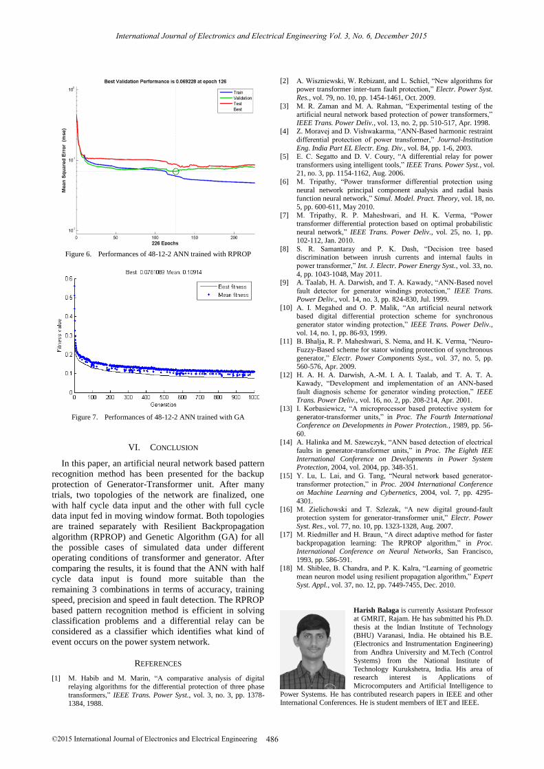
Figure 6. Performances of 48-12-2 ANN trained with RPROP
Figure 7. Performances of 48-12-2 ANN trained with GA
VI. CONCLUSION
In this paper, an artificial neural network based pattern
recognition method has been presented for the backup
protection of Generator-Transformer unit. After many
trials, two topologies of the network are finalized, one
with half cycle data input and the other with full cycle
data input fed in moving window format. Both topologies
are trained separately with Resilient Backpropagation
algorithm (RPROP) and Genetic Algorithm (GA) for all
the possible cases of simulated data under different
operating conditions of transformer and generator. After
comparing the results, it is found that the ANN with half
cycle data input is found more suitable than the
remaining 3 combinations in terms of accuracy, training
speed, precision and speed in fault detection. The RPROP
based pattern recognition method is efficient in solving
classification problems and a differential relay can be
considered as a classifier which identifies what kind of
event occurs on the power system network.
REFERENCES
[1] M. Habib and M. Marin, “A comparative analysis of digital relaying algorithms for the differential protection of three phase
transformers,” IEEE Trans. Power Syst., vol. 3, no. 3, pp. 1378-
1384, 1988.
[2] A. Wiszniewski, W. Rebizant, and L. Schiel, “New algorithms for
power transformer inter-turn fault protection,” Electr. Power Syst.
Res., vol. 79, no. 10, pp. 1454-1461, Oct. 2009.
[3] M. R. Zaman and M. A. Rahman, “Experimental testing of the artificial neural network based protection of power transformers,”
IEEE Trans. Power Deliv., vol. 13, no. 2, pp. 510-517, Apr. 1998. [4] Z. Moravej and D. Vishwakarma, “ANN-Based harmonic restraint
differential protection of power transformer,” Journal-Institution
Eng. India Part EL Electr. Eng. Div., vol. 84, pp. 1-6, 2003. [5] E. C. Segatto and D. V. Coury, “A differential relay for power
transformers using intelligent tools,” IEEE Trans. Power Syst., vol. 21, no. 3, pp. 1154-1162, Aug. 2006.
[6] M. Tripathy, “Power transformer differential protection using
neural network principal component analysis and radial basis function neural network,” Simul. Model. Pract. Theory, vol. 18, no.
5, pp. 600-611, May 2010. [7] M. Tripathy, R. P. Maheshwari, and H. K. Verma, “Power
transformer differential protection based on optimal probabilistic
neural network,” IEEE Trans. Power Deliv., vol. 25, no. 1, pp. 102-112, Jan. 2010.
[8] S. R. Samantaray and P. K. Dash, “Decision tree based
discrimination between inrush currents and internal faults in
power transformer,” Int. J. Electr. Power Energy Syst., vol. 33, no.
4, pp. 1043-1048, May 2011. [9] A. Taalab, H. A. Darwish, and T. A. Kawady, “ANN-Based novel
fault detector for generator windings protection,” IEEE Trans. Power Deliv., vol. 14, no. 3, pp. 824-830, Jul. 1999.
[10] A. I. Megahed and O. P. Malik, “An artificial neural network
based digital differential protection scheme for synchronous generator stator winding protection,” IEEE Trans. Power Deliv.,
vol. 14, no. 1, pp. 86-93, 1999. [11] B. Bhalja, R. P. Maheshwari, S. Nema, and H. K. Verma, “Neuro-
Fuzzy-Based scheme for stator winding protection of synchronous
generator,” Electr. Power Components Syst., vol. 37, no. 5, pp. 560-576, Apr. 2009.
[12] H. A. H. A. Darwish, A.-M. I. A. I. Taalab, and T. A. T. A. Kawady, “Development and implementation of an ANN-based
fault diagnosis scheme for generator winding protection,” IEEE
Trans. Power Deliv., vol. 16, no. 2, pp. 208-214, Apr. 2001. [13] I. Korbasiewicz, “A microprocessor based protective system for
generator-transformer units,” in Proc. The Fourth International Conference on Developments in Power Protection., 1989, pp. 56-
60.
[14] A. Halinka and M. Szewczyk, “ANN based detection of electrical faults in generator-transformer units,” in Proc. The Eighth IEE
International Conference on Developments in Power System Protection, 2004, vol. 2004, pp. 348-351.
[15] Y. Lu, L. Lai, and G. Tang, “Neural network based generator-
transformer protection,” in Proc. 2004 International Conference on Machine Learning and Cybernetics, 2004, vol. 7, pp. 4295-
4301. [16] M. Zielichowski and T. Szlezak, “A new digital ground-fault
protection system for generator-transformer unit,” Electr. Power
Syst. Res., vol. 77, no. 10, pp. 1323-1328, Aug. 2007. [17] M. Riedmiller and H. Braun, “A direct adaptive method for faster
backpropagation learning: The RPROP algorithm,” in Proc. International Conference on Neural Networks, San Francisco,
1993, pp. 586-591.
[18] M. Shiblee, B. Chandra, and P. K. Kalra, “Learning of geometric mean neuron model using resilient propagation algorithm,” Expert
Syst. Appl., vol. 37, no. 12, pp. 7449-7455, Dec. 2010.
Harish Balaga is currently Assistant Professor at GMRIT, Rajam. He has submitted his Ph.D.
thesis at the Indian Institute of Technology (BHU) Varanasi, India. He obtained his B.E.
(Electronics and Instrumentation Engineering)
from Andhra University and M.Tech (Control Systems) from the National Institute of
Technology Kurukshetra, India. His area of research interest is Applications of
Microcomputers and Artificial Intelligence to
Power Systems. He has contributed research papers in IEEE and other International Conferences. He is student members of IET and IEEE.
International Journal of Electronics and Electrical Engineering Vol. 3, No. 6, December 2015
©2015 International Journal of Electronics and Electrical Engineering 486

Harshit Nath is presently a final year student
of BE in Electrical Engineering at Thapar
University, Patiala, India. He has undergone
practical internship training at HVDC Back to Back Substation of Power Grid Corporation of
India. His area of research interest is Applications of Microcomputers and Artificial
Intelligence to Power Systems. He has worked
on Applications of Artificial Intelligence to Power System Protection at IIT (BHU),
Varanasi during summer vacations. He has contributed research papers in IEEE and other International Conferences. He is student members of
IET and IEEE.
Devendra Nath Vishwakarma is currently
Professor of Electrical Engineering at the
Indian Institute of Technology (BHU)
Varanasi, India. He obtained his B.Sc. (Engineering), M.Sc. (Engineering) and Ph.D.
from Patna University, Patna. He had earlier served as associate professor of electrical
engineering at the Bihar College of
Engineering, Patna (Presently National Institute of Technology Patna). He has a
teaching and research experience of over 35 years and has contributed about 65 papers to various national and international journals and
conferences. He is coauthor of the book, “Power System Protection and
Switchgear” published by McGraw Hill education (India) private limited. He is a senior member of IEEE (USA), a fellow of the
Institution of Engineers (India) and a fellow of the Institution of Electronics and Telecommunication Engineers.
International Journal of Electronics and Electrical Engineering Vol. 3, No. 6, December 2015
©2015 International Journal of Electronics and Electrical Engineering 487