Ball Dribbling for Humanoid Biped Robots: A Reinforcement ...
5
Artificial Muscles for Humanoid Robots
Bertrand Tondu LESIA, Institut National de Sciences Appliquées de Toulouse
Campus Universitaire de Rangueil, 31077 Toulouse France
1. The question of actuator choice for humanoid robots
It is important to recall that humanoid robot technology derives from the technology of industrial robots. It is obvious that the developments of bipedal robots such as the integration of robot-upper limbs to complex anthropomorphic structures have benefited from progress in mechanical structures, sensors and actuators used in industrial robot-arms. A direct link is sometimes made between the technology of redundant robot-arms and humanoid robots as underlined in some technical documents of the Japanese AIST where it clearly appears that the HRP2 humanoid robot upper limb is directly derived from the Mitsubshi PA10 7R industrial robot-arm. Due to its high number of degrees of freedom in comparison to industrial robots, a humanoid robot requires great compactness of all actuator and sensor components. This is why we believe that the harmonic drive technology associated with direct current electric motor technology has played a non-negligible part in humanoid robot development. The DC actuator offers the great advantage of being a straightforward technology, associated with simple and well-known physical models, its integration into mobile robots benefits from new developments in embedded batteries. However, its low maximum-torque-on-mass and maximum-torque-on- volume ratios are a serious drawback for its use in direct drive apparatuses. On the other hand, the ability of electric motors to generate very high velocities in comparison with moderate jointed velocities needed by industrial robot-arms and more by jointed anthropomorphic limbs, gives the possibility of using high ratio speed reducers to amplify motor-torque. Moreover, the choice of a high ratio speed reducer offers the advantage of masking inertial perturbations such as external torque perturbations. The technical achievement of such ratios induces specific mechanical difficulties due to the bulkiness of successive gears; harmonic drive technology – represented for example by Harmonic Drive AG – resolves this problem in a very elegant manner: the harmonic drive and the actuator fit together without excessive increase in mass and volume in comparison with the actuator alone. It can be considered that most of today’s humanoid robots are actuated by DC motors with harmonic drives (this actuation mode is mentioned, for example, by Honda from its first paper about the P2 robot onwards (Hirai et al., 1998) and then in the official ASIMO web site, as well as in papers concerning other Japanese and European humanoid robots). But if this technology simplifies actuator mechanical integration and leads to the use of simple joint linear control, despite the highly non-linear character of robot dynamics, it is well-known that the use of a speed reducer multiplies the
Source: Humanoid Robots: Human-like Machines, Book edited by: Matthias HackelISBN 978-3-902613-07-3, pp. 642, Itech, Vienna, Austria, June 2007
Ope
n A
cces
s D
atab
ase
ww
w.i-
tech
onlin
e.co
m
Humanoid Robots, Human-like Machines 90
joint stiffness by the its ratio squared. A high joint stiffness contributes to joint accuracy and repeatability, but also induces a high danger level for users, which can be acceptable in the case of industrial robot-arms separated from factory staff by special safety devices, but becomes very problematical in the case of humanoid robots intended for working in public environments. The need to find an actuation mode which associates power, accuracy and a ‘softness’ adapted to human presence, that is the question of actuator choice in humanoid robotics. To address this problem we will first try to define the notion of artificial muscle in paragraph 2, then deal with the question of artificial muscle actuators for humanoid robots in paragraph 3, before analysing their integration within anthropomorphic limbs (paragraph 4) to finish with their control (paragraph 5).
2. Notion of artificial muscle
2.1 Performance criteria in the research of new actuators
A general theory of actuators does not exist; each actuator is defined according to the physical theory on which its legitimacy is founded. A comparison of actuators can as a consequence be delicate. This is why actuator designers have introduced a certain number of performance criteria aimed at making such comparisons easier. In general, actuation can be defined as a process of converting energy to mechanical forms, and an actuator as a device that accomplishes this conversion. Power output per actuator mass, and per
volume, as actuator efficiency – defined as ‘the ratio of mechanical work output to energy input during a complete cycle in cyclic operation ‘ (Huber et al., 1997) - are three fundamental properties for characterizing actuators. However, artificial muscle technology considers more specific performance criteria so as to accurately specify new actuator technology in comparison with ‘natural muscular motor’ properties. The following terminology, justified by the linear actuator character of the artificial muscle, generally completes the power criteria – the definitions given in inverted commas are from (Madden et al., 2004) :
• Stress : ‘typical force per cross-sectional area under which the actuator materials are tested’; maximum stress corresponds to the maximum stress that can be generated in specified functioning conditions; as will be seen later, it is important for a given technology to specify the ‘actuator materials’ relating to stress: typical stresses of strips or fibres of a given technology is not obligatorily similar to that of the artificial muscle composed of a set of these strips or fibres;
• Strain : ‘displacement normalized by the original material length in the direction of actuation’; maximum strain and maximum stress are according to Huber & others ‘basic characteristics of an actuator [since] for a given size of actuator they limit the force and displacement’ (Huber et al., 1997, p. 2186); the terms contraction ratio and maximum contraction ratio will also be used;
• Strain rate : ‘average change in strain per unit time during an actuator stroke’; the term ‘response time’ – in the sense given by control theory, will also be used to characterize the speed of artificial muscle dynamic contraction;
• Cycle life : ‘number of useful strokes that the material is known to be able to undergo’; this notion specifies the heavy-duty character of artificial muscle in given working conditions; in practice this is an important notion since artificial muscles are essentially made of ‘soft’ materials which can be weakened by shape changes imposed by the actuation mode;
Artificial Muscles for Humanoid Robots 91
• Elastic modulus: ‘material stiffness multiplied by sample length and divided by cross-sectional area’; this is a typical material science notion; when the artificial muscle is considered as an actuator to be controlled, stiffness – and its inverse - compliance
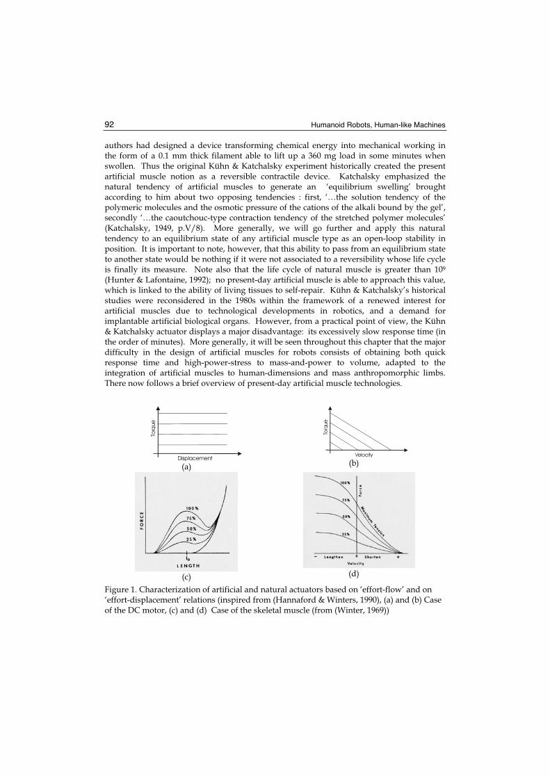
notions can appear more appropriate. It is important to note that this criteria list is not exhaustive; depending on author, other performance criteria can be found: as an example, Huber et al consider two criteria not listed above: actuator density (the ratio of mass to initial volume of an actuator) and strain resolution (the smallest step increment of strain) (Huber et al., 1997). The first directly concerns humanoid robotics: like skeletal muscles, artificial muscles are assumed to be located in moving robot links; the second criterion can be interesting in a control perspective to specify artificial muscle sensitivity. Furthermore, we believe that the theoretical framework proposed by Hannaford and Winters (Hannaford & Winters, 1990) for the analysis of actuator properties based on Paynter’s terminology of generalized dynamic systems (Paynter, 1961) can be particularly useful in our study: these authors propose characterizing any actuator by its two effort-flow and effort-displacement characteristics, where ‘effort’ represents the output force or torque, and ‘flow’ the linear velocity or angular velocity. For example, the DC motor is ideally characterized by a linear effort-flow curve and a constant effort-displacement curve, as illustrated in Figures 1.a and 1.b. Figures 1.c and 1.d give the typical characteristics of the skeletal muscle by the association of ‘effort-flow’ characteristics corresponding to the so-called tension-velocity curve with the ‘effort-displacement’ characteristics corresponding to the so-called tension-length curve. We will return to this in the modelling of skeletal muscle, but it is important to note the fundamental originality of skeletal muscle characteristics: while most of the actuators have constant or pseudo-constant ‘effort-displacement’ characteristics, this is not so for skeletal muscle. As a dynamic system in Paynter’s sense, the ‘effort-displacement’ relationship defines passive element C (for compliance or capacitance). Classical actuators generally have infinite compliance; a dependence of force/torque on position can even appear as a drawback: it is up to the actuator control and not the actuator itself to impose this dependence. Conversely, living actuators aimed at a ‘relationship life’ have to combine the generation of the power necessary for body mobility with a non-infinite compliance making for easy contact with the environment – we will use later the term ‘natural’ compliance to characterize this compliance peculiar to the skeletal actuator. Research on artificial muscles can be understood as a new attempt to mimic the living so as to integrate it into a machine – the humanoid robot – an original power-softness combination, yet glaringly absent in machine technology.
2.2 The historical Kühn and Katchalsky notion of artificial muscle as a gel swelling and deswelling under the effect of a chemical agent
The origin of the artificial muscle notion must be found in the first works of chemists on certain materials whose swelling can be controlled in a reversible manner. At the end of the 1940s, Kühn & Katchalsky did indeed prove that an aqueous polymeric gel essentially composed of polyacrylic acid ‘… is found to swell enormously on addition of alkali and to contract rapidly when acid is added to the surrounding solution. Linear dilatations and contractions of the order of 300 per cent were observed. This cycle of swelling and de-swelling is reversible and can be repeated at will ‘ (Kühn et al., 1950, p.515). At that time the
Humanoid Robots, Human-like Machines 92
authors had designed a device transforming chemical energy into mechanical working in the form of a 0.1 mm thick filament able to lift up a 360 mg load in some minutes when swollen. Thus the original Kühn & Katchalsky experiment historically created the present artificial muscle notion as a reversible contractile device. Katchalsky emphasized the natural tendency of artificial muscles to generate an ‘equilibrium swelling’ brought according to him about two opposing tendencies : first, ‘…the solution tendency of the polymeric molecules and the osmotic pressure of the cations of the alkali bound by the gel’, secondly ‘…the caoutchouc-type contraction tendency of the stretched polymer molecules’ (Katchalsky, 1949, p.V/8). More generally, we will go further and apply this natural tendency to an equilibrium state of any artificial muscle type as an open-loop stability in position. It is important to note, however, that this ability to pass from an equilibrium state to another state would be nothing if it were not associated to a reversibility whose life cycle is finally its measure. Note also that the life cycle of natural muscle is greater than 109
(Hunter & Lafontaine, 1992); no present-day artificial muscle is able to approach this value, which is linked to the ability of living tissues to self-repair. Kühn & Katchalsky’s historical studies were reconsidered in the 1980s within the framework of a renewed interest for artificial muscles due to technological developments in robotics, and a demand for implantable artificial biological organs. However, from a practical point of view, the Kühn & Katchalsky actuator displays a major disadvantage: its excessively slow response time (in the order of minutes). More generally, it will be seen throughout this chapter that the major difficulty in the design of artificial muscles for robots consists of obtaining both quick response time and high-power-stress to mass-and-power to volume, adapted to the integration of artificial muscles to human-dimensions and mass anthropomorphic limbs. There now follows a brief overview of present-day artificial muscle technologies.
(a) (b)
(c) (d)
Figure 1. Characterization of artificial and natural actuators based on ‘effort-flow’ and on ‘effort-displacement’ relations (inspired from (Hannaford & Winters, 1990), (a) and (b) Case of the DC motor, (c) and (d) Case of the skeletal muscle (from (Winter, 1969))
Displacement
Torq
ue
Velocity
Torq
ue

Artificial Muscles for Humanoid Robots 93
2.3 The artificial muscle as any material structure exhibiting a reversible shape change by a chemical or a physical agent
a. Contractile polymer gels Aqueous solutions of polymeric acids considered by Kühn & Katchalsky are a particular case of solvent-swollen crosslinked polymer gels that respond to changes in temperature, pH, solvent, illumination, or other physical or chemical stimuli. The choice of pH or a solvent as a stimulus applied to typically polyacrylamide (PAM), polyvinyl alcohol-polyacrylic acid (PVA-PAA) or polyacrylonitrile (PAN) fibers or strips (all commercially available) is particularly interesting due to the facility of producing the pH variation by adding of acid or alkali solutions (typically through the control of the hydrogen ion by means of chemical reactions with HCl and NaOH) or the facility of using cheap and readily available solvent like acetone. Parallel to a better understanding of gels physics it has been possible to develop micro sized gel fibers contracting in seconds and even tenths of seconds and to increase both the force produced by gel fibers as resistance fibers (some of them can support loads of about 100 N/cm2 approximatively equal to that of human muscle. M. Suzuki, for example, has developed in the nineties a 12 cm length artificial muscle model by
PVA-PAA-PA1Am gel film of 50μm thickness able to raise a ball of 2 g from a lower equilibrium position to an upper equilibrium position within 10 s (Suzuki, 1991). Although in these conditions, the maximum power density obtained with gel fibres can indeed be estimated as being close to that of skeletal muscle, it still appears difficult to apply this technology to the actuation of human-sized robot limbs. However, later we will analyse the interesting attempt made at the MIT in the 1990s to promote ‘pH muscle’ The relative slowness of the complete contraction-elongation cycle of ion sensitive gel fibre is mainly due to the relative slowness of the ion sensitive mechanism itself. For this reason, other stimulus modes were considered, in particular heat transfer since heat diffusion is better than ion diffusion. Thermo-responsive polymer hydrogels are already used in drug release, and the study of tensile properties of thermo-responsive gels have been clearly established (Kim et al., 2005). In the field of artificial muscles, this stimulus mode seems, however, to have been more studied in the case of fairly recent polymer types – in particular liquid crystal polymers – assumed to respond quicker than gel fibres. In any case, for gels as for other materials, thermal response always appears quicker in the heating than in the cooling phase (we will not deal in this chapter with the promising technology of liquid crystal polymers able to respond to a luminous flash in less than a second, but as noted by De Gennes (De Gennes et al., 1997) which predicted their contractile possibilities and talked of them as ‘semi-quick artificial muscles’, the return to low temperatures is slow).b. Shape memory alloys Another form of reversible thermal response can be generated by means of thermally activated shape memory alloys based on the ‘shape memory effect’ discovered at the beginning of the 1950s. Among available materials nickel-titanium alloys (NiTi or nitinol) are particularly interesting for actuation use because of their low cost and electrical resistivity which heats the material by passing an electrical current. Due to this Joule heating, NiTi contraction and expansion cycles can occur based on transformations from martensitic to austenitic phases. Typically a shape is ‘memorized’ at a high temperature (600°) placing the nitinol in austenite phase. On decreasing the temperature, the material reverts to the martensite phase. When an external stress is applied, and as the material is reheated at a lower temperature the material, because of the instability of the martensite
Humanoid Robots, Human-like Machines 94
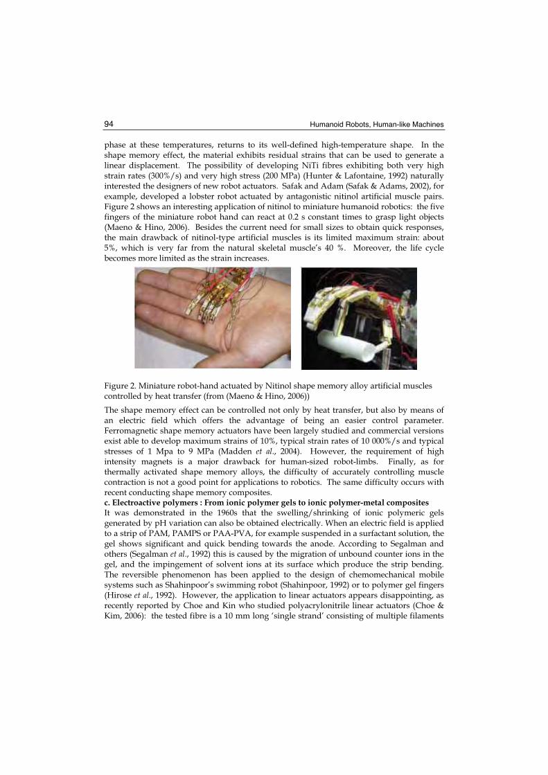
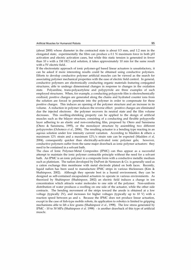
phase at these temperatures, returns to its well-defined high-temperature shape. In the shape memory effect, the material exhibits residual strains that can be used to generate a linear displacement. The possibility of developing NiTi fibres exhibiting both very high strain rates (300%/s) and very high stress (200 MPa) (Hunter & Lafontaine, 1992) naturally interested the designers of new robot actuators. Safak and Adam (Safak & Adams, 2002), for example, developed a lobster robot actuated by antagonistic nitinol artificial muscle pairs. Figure 2 shows an interesting application of nitinol to miniature humanoid robotics: the five fingers of the miniature robot hand can react at 0.2 s constant times to grasp light objects (Maeno & Hino, 2006). Besides the current need for small sizes to obtain quick responses, the main drawback of nitinol-type artificial muscles is its limited maximum strain: about 5%, which is very far from the natural skeletal muscle’s 40 %. Moreover, the life cycle becomes more limited as the strain increases.
Figure 2. Miniature robot-hand actuated by Nitinol shape memory alloy artificial muscles controlled by heat transfer (from (Maeno & Hino, 2006))
The shape memory effect can be controlled not only by heat transfer, but also by means of an electric field which offers the advantage of being an easier control parameter. Ferromagnetic shape memory actuators have been largely studied and commercial versions exist able to develop maximum strains of 10%, typical strain rates of 10 000%/s and typical stresses of 1 Mpa to 9 MPa (Madden et al., 2004). However, the requirement of high intensity magnets is a major drawback for human-sized robot-limbs. Finally, as for thermally activated shape memory alloys, the difficulty of accurately controlling muscle contraction is not a good point for applications to robotics. The same difficulty occurs with recent conducting shape memory composites. c. Electroactive polymers : From ionic polymer gels to ionic polymer-metal composites It was demonstrated in the 1960s that the swelling/shrinking of ionic polymeric gels generated by pH variation can also be obtained electrically. When an electric field is applied to a strip of PAM, PAMPS or PAA-PVA, for example suspended in a surfactant solution, the gel shows significant and quick bending towards the anode. According to Segalman and others (Segalman et al., 1992) this is caused by the migration of unbound counter ions in the gel, and the impingement of solvent ions at its surface which produce the strip bending. The reversible phenomenon has been applied to the design of chemomechanical mobile systems such as Shahinpoor’s swimming robot (Shahinpoor, 1992) or to polymer gel fingers (Hirose et al., 1992). However, the application to linear actuators appears disappointing, as recently reported by Choe and Kin who studied polyacrylonitrile linear actuators (Choe & Kim, 2006): the tested fibre is a 10 mm long ‘single strand’ consisting of multiple filaments
Artificial Muscles for Humanoid Robots 95
(about 2000) whose diameter in the contracted state is about 0.5 mm, and 1.2 mm in the elongated state; experimentally the fibre can produce a 0.1 N maximum force in both pH activation and electric activation cases, but while this static tension is generated in fewer than 10 s with a 1M HCl acid solution, it takes approximately 10 min for the same result with a 5V electric field.. If the electrostatic approach of ionic polymer-gel based linear actuators is unsatisfactory, it can be asked if more interesting results could be obtained using conductive polymers. Efforts to develop conductive polymer artificial muscles can be viewed as the search for associating polymer mechanical properties with the ease of electric field control. In general, conductive polymers are electronically conducting organic materials featuring conjugated structures, able to undergo dimensional changes in response to changes in the oxidation state. Polyaniline, trans-polyacetylene and polypyrrole are three examples of such employed structures. When, for example, a conducting polypyrole film is electrochemically oxidized, positive charges are generated along the chains and hydrated counter ions from the solution are forced to penetrate into the polymer in order to compensate for these positive charges. This induces an opening of the polymer structure and an increase in its volume. A reduction in polymer induces the reverse effect: positive charges are eliminated due the injected electrons: the polymer recovers its neutral state and the film volume decreases. This swelling-shrinking property can be applied to the design of artificial muscles such as the bilayer structure, consisting of a conducting and flexible polypyrolle layer adhering to an elastic and non-conducting film, proposed by Otero and Sansinena (Otero & Sansinena, 1995), or the monolayer structure by assembling two different polypyrroles (Ochoteco et al., 2006). The resulting actuator is a bending type reacting in an aqeous solution under low intensity current variation. According to Madden & others a maximum 12% strain and a maximum 12%/s strain rate can be expected (Madden et al,2004), consequently quicker than electrically-activated ionic polymer gels; however, conductive polymers suffer from the same major drawback as ionic polymer actuators: they need to be contained in a solvant bath. The class of Ionic Polymer-Metal Composites (IPMC) can thus appear as a successful attempt to maintain the ionic polymer contractile principle without the need for a solvant bath. An IPMC is an ionic polymer in a composite form with a conductive metallic medium such as platinium. The nafion developed by DuPont de Nemours & Co. is generally used as a cation exchange thin membrane with metal electrode plated on both faces. Recently, liquid nafion has been used to manufacture IPMC strips in various thicknesses (Kim & Shahinpoor, 2002). Although they operate best in a humid environment, they can be designed as self-contained encapsulated actuators to operate in various environments. As theorized by Shahinpoor (Shahinpoor, 2002) an electric field induces a change in ion concentration which attracts water molecules to one side of the polymer. Non-uniform distribution of water produces a swelling on one side of the actuator, while the other side contracts. The bending movement of the strips toward the anode is obtained at a low voltage (typically 2V), and increases for higher voltages (typically up to 10 V) with a
reaction speed between μs and s. Because the IPMC does not produce linear actuation, except in the case of fish-type mobile robots, its application to robotics is limited to gripping mechanisms able to lift a few grams (Shahinpoor et al., 1998). The low stress generated by IPMC - 10 to 30 MPa (Shahinpoor et al. 1998) - is another drawback of this type of artificial muscle.
Humanoid Robots, Human-like Machines 96
d. Electroactive polymers : Dielectric elastomers Dielectric elastomer actuator technology appeared in the middle of the 1990s. As will be analysed in paragraph 3, this technology is considered as one of the most promising for developing artificial muscles adapted to robot-limbs (Bar-Cohen, 2004). As in IPMC technology, polymer shape change can be induced in dry environments, but at the expense of higher stresses. A dielectric elastomer actuator can be considered as a compliant capacitor inducing a stress when the capacitor is charged. According to Maxwell’s theory applied to a constant volume elastomer, stress p and strains SX , SY , SZ of the dielectric elastomer (assuming small, e.g. < 10%), respectively, in X, Y and Z directions, as illustrated in Figures 3.a and 3.b, can be written as follows (Pelrine et al., 1998), (Pelrine et al., 2002) :
=+++
−=
=
1)1)(1)(1(
)/(
)/(22
0
20
ZYX
Z
SSS
YtVeeS
tVeep
(1)
where e0 is the permittivity of free space, e the polymer dielectric constant, V applied voltage, t polymer thickness and Y elasticity modulus of the polymer-electrode composite film. These three equations constitute a simplified model (limited by the assumption of small strains) but which highlights the main parameters participating in the dimensioning of the actuator: polymer dielectric constant e - e is equal to 1 for air – varies between 3 to 10 according to elastomer choice (Mathew et al., 2006) and electric field E = V/t whose value, depending as it does on the elastomer, is an important factor in increasing actuation stress by a factor of 10 to 100 compared to conventional electrostatic actuators. The simplicity and relative efficiency of this model contrasts with the complexity of Flory’s model which includes polymer gels swelling, in association with the difficulty of parametrizing the conductive polymers. Performances of dielectric elastomers are particularly interesting in comparison with other artificial muscle technologies as well as with natural muscle (Pelrine et al., 2000) because they can associate high maximum strain, high maximum stress and low response times: in the case of a silicone elastomer, a maximum strain of 32 % can be generated with a maximum stress of 1.36 Mpa, and a time response of some msec. Furthermore, their ability to be configured in many ways is particularly important for robotics. The next paragraph analyses how linear actuators can be derived from this technology. Two main disadvantages, however, have to be highlighted: firstly, dielectric elastomers operate at relatively high voltages (100-4000 V), and secondly, due to their capacity, electrical energy remains after actuation, which in practice requires energy recovery circuits. e. Elastomer inflatable structures Physical elastomer properties are also at the origin of another large class of artificial muscles that recent advances in chemo-mechanical actuators have pushed into the background. They are not mentioned in numerous synthesis articles. We propose to call them ‘elastomer inflatable structures’ because they are based on the unique property of elastomers to support very large strains (up to 600%) without damage. Whereas the dielectric elastomer operation principle is based on the generation of a compression stress, the operation principle of elastomer inflatable structures is based on tensile stress. Thanks to a specific guiding structure, which will be specified in paragraph 3, the stress generated inside the
Artificial Muscles for Humanoid Robots 97
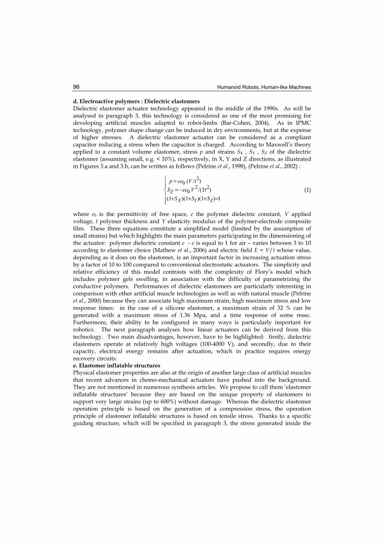
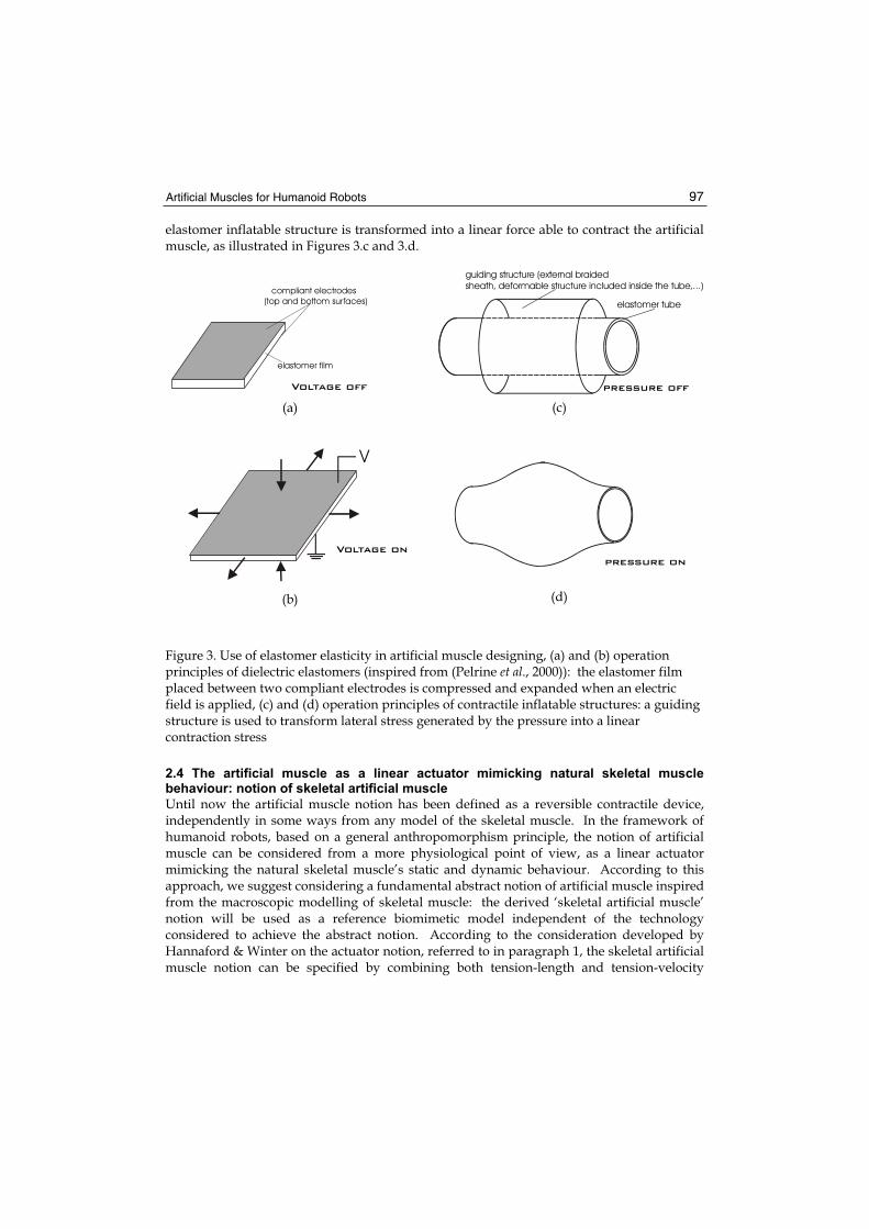
elastomer inflatable structure is transformed into a linear force able to contract the artificial muscle, as illustrated in Figures 3.c and 3.d.
(a) (c)
(b) (d)
Figure 3. Use of elastomer elasticity in artificial muscle designing, (a) and (b) operation principles of dielectric elastomers (inspired from (Pelrine et al., 2000)): the elastomer film placed between two compliant electrodes is compressed and expanded when an electric field is applied, (c) and (d) operation principles of contractile inflatable structures: a guiding structure is used to transform lateral stress generated by the pressure into a linear contraction stress
2.4 The artificial muscle as a linear actuator mimicking natural skeletal muscle behaviour: notion of skeletal artificial muscle
Until now the artificial muscle notion has been defined as a reversible contractile device, independently in some ways from any model of the skeletal muscle. In the framework of humanoid robots, based on a general anthropomorphism principle, the notion of artificial muscle can be considered from a more physiological point of view, as a linear actuator mimicking the natural skeletal muscle’s static and dynamic behaviour. According to this approach, we suggest considering a fundamental abstract notion of artificial muscle inspired from the macroscopic modelling of skeletal muscle: the derived ‘skeletal artificial muscle’ notion will be used as a reference biomimetic model independent of the technology considered to achieve the abstract notion. According to the consideration developed by Hannaford & Winter on the actuator notion, referred to in paragraph 1, the skeletal artificial muscle notion can be specified by combining both tension-length and tension-velocity
Voltage on
V
compliant electrodes(top and bottom surfaces)
elastomer film
Voltage off
pressure on
guiding structure (external braidedsheath, deformable structure included inside the tube,...)
elastomer tube
pressure off
Humanoid Robots, Human-like Machines 98
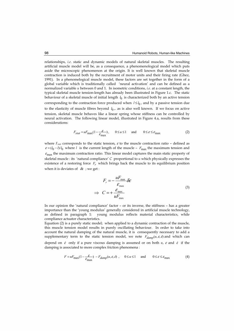
relationships, i.e. static and dynamic models of natural skeletal muscles. The resulting artificial muscle model will be, as a consequence, a phenomenological model which puts aside the microscopic phenomenon at the origin. It is well known that skeletal muscle contraction is induced both by the recruitment of motor units and their firing rate (Ghez, 1991). In a phenomelogical muscle model, these factors are set together in the form of a global variable which is traditionally called ‘neural activation’ and can be defined as a normalized variable u between 0 and 1. In isometric conditions, i.e. at a constant length, the typical skeletal muscle tension-length has already been illustrated in Figure 1.c. The static
behaviour of a skeletal muscle of initial length 0l is characterized both by an active tension
corresponding to the contraction force produced when 0ll ≤ , and by a passive tension due
to the elasticity of muscle fibres beyond 0l ,. as is also well known. If we focus on active
tension, skeletal muscle behaves like a linear spring whose stiffness can be controlled by neural activation. The following linear model, illustrated in Figure 4.a, results from these considerations:
maxmax
max 0and10,)1( εεε
ε ≤≤≤≤−= uuFFstat (2)
where Fstat corresponds to the static tension, ε to the muscle contraction ratio – defined as
00 /)( lll −=ε where l is the current length of the muscle – maxF the maximum tension and
maxε the maximum contraction ratio. This linear model captures the main static property of
skeletal muscle : its ‘natural compliance’ C proportional to u which physically expresses the
existence of a restoring force rF which brings back the muscle to its equilibrium position
when it is deviates of δε ; we get :
max
max
max
max
uFC
uFFr
ε
δεε
+=
−=
(3)
In our opinion the ‘natural compliance’ factor – or its inverse, the stiffness – has a greater importance than the ‘young modulus’ generally considered in artificial muscle technology, as defined in paragraph 1: young modulus reflects material characteristics, while compliance actuator characteristics. Equation (2) is a purely static model; when applied to a dynamic contraction of the muscle, this muscle tension model results in purely oscillating behaviour. In order to take into account the natural damping of the natural muscle, it is consequently necessary to add a supplementary term to the static tension model, we note ),,( εεuFdamp and which can
depend on ε only if a pure viscous damping is assumed or on both u, ε and ε if the
damping is associated to more complex friction phenomena :
maxmax
max 0and10,),,()1( εεεεε
ε ≤≤≤≤−−= uuFuFF damp (4)
Artificial Muscles for Humanoid Robots 99
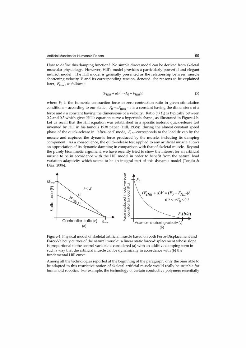
How to define this damping function? No simple direct model can be derived from skeletal muscular physiology. However, Hill’s model provides a particularly powerful and elegant indirect model . The Hill model is generally presented as the relationship between muscle shortening velocity V and its corresponding tension, denoted for reasons to be explained
later, HillF , as follows :
bFFVaF HillHill )()( 0 −=+ (5)
where F0 is the isometric contraction force at zero contraction ratio in given stimulation
conditions – according to our static : max0 uFF = – a is a constant having the dimensions of a
force and b a constant having the dimensions of a velocity. Ratio (a/F0) is typically between 0.2 and 0.3 which gives Hill’s equation curve a hyperbola shape , as illustrated in Figure 4.b. Let us recall that the Hill equation was established in a specific isotonic quick-release test invented by Hill in his famous 1938 paper (Hill, 1938): during the almost constant speed
phase of the quick-release in ‘after-load’ mode, HillF corresponds to the load driven by the
muscle and captures the dynamic force produced by the muscle, including its damping component. As a consequence, the quick-release test applied to any artificial muscle allows an appreciation of its dynamic damping in comparison with that of skeletal muscle. Beyond the purely biomimetic argument, we have recently tried to show the interest for an artificial muscle to be in accordance with the Hill model in order to benefit from the natural load variation adaptivity which seems to be an integral part of this dynamic model (Tondu & Diaz, 2006).
(a) (b)
Figure 4. Physical model of skeletal artificial muscle based on both Force-Displacement and Force-Velocity curves of the natural muscle: a linear static force-displacement whose slope is proportional to the control variable is considered (a) with an additive damping term in such a way that the artificial muscle can be dynamically in accordance with (b) the fundamental Hill curve
Among all the technologies reported at the beginning of the paragraph, only the ones able to be adapted to this restrictive notion of skeletal artificial muscle would really be suitable for humanoid robotics. For example, the technology of certain conductive polymers essentially
bFFVaF HillHill )()( 0 −=+
3.0/2.0 0 ≤≤ Fa
Maximum shortening velocity (V)
Forc
e p
rod
uc
ed
in q
uic
k-re
lea
se
co
nd
itio
n (o
r lo
ad
) (F
)H
ill
bFFVaF HillHill )()( 0
F0
F b/a0( )
3.0/2.0 0Fa
Contraction ratio ( )ε
Sta
tic fo
rce
(F)
uFmax
u’
u
εmax
δεFr
u u’<
Humanoid Robots, Human-like Machines 100
leads to bending artificial muscle difficulty applicable to linear actuators. Let us now analyse some attempts at artificial skeletal muscle.
3. Which artificial muscle technology for anthropomorphic limbs?
The three technologies that we present have all led to artificial muscles of skeletal muscle size; they illustrate the present diversity of the stimulus mode: chemical for pH muscle, electrical for roll actuator and fluidic for pneumatic muscles. It could be said that because nobody is currently able to mimic the complex sequence of biomechanical microscopic phenomena of natural skeletal muscle, the energy choice question of artificial muscle remains open.
3.1 pH-sensitive muscles and Solvent-sensitive muscles
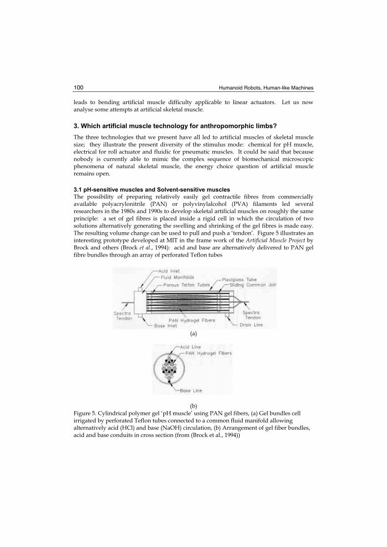
The possibility of preparing relatively easily gel contractile fibres from commercially available polyacrylonitrile (PAN) or polyvinylalcohol (PVA) filaments led several researchers in the 1980s and 1990s to develop skeletal artificial muscles on roughly the same principle: a set of gel fibres is placed inside a rigid cell in which the circulation of two solutions alternatively generating the swelling and shrinking of the gel fibres is made easy. The resulting volume change can be used to pull and push a ‘tendon’. Figure 5 illustrates an interesting prototype developed at MIT in the frame work of the Artificial Muscle Project by Brock and others (Brock et al., 1994): acid and base are alternatively delivered to PAN gel fibre bundles through an array of perforated Teflon tubes
(a)
(b)Figure 5. Cylindrical polymer gel ‘pH muscle’ using PAN gel fibers, (a) Gel bundles cell irrigated by perforated Teflon tubes connected to a common fluid manifold allowing alternatively acid (HCl) and base (NaOH) circulation, (b) Arrangement of gel fiber bundles, acid and base conduits in cross section (from (Brock et al., 1994))
Artificial Muscles for Humanoid Robots 101
The ‘pH muscle’ is used in antagonism with a spring and a modular pulley system: using a simple bang-bang control a rotation from 0 to 70° is generated in approximatively 45 seconds with a maximum tension of 0.35 N. The confrontation of this experimental device resulting from Caldwell’s experiments leads to a better understanding of the difficulty of adapting this technology to powerful skeletal artificial muscles. The ‘solvent-sensitive muscle’ cell imagined by Caldwell (Caldwell & Taylor, 1990), (Caldwell et al., 2000) is made of parallel PAA/PVA strips inside a container where an acetone and 4 molar NaCl solution
can alternatively circulate. Originally (Caldwell & Taylor, 1990) 100 μm thick strips were used, but more recently it was shown (Caldwell et al., 2000) that it was possible to optimize the thickness choice so as to highly increase contraction velocity without losing in stress: a
50 μm thickness gives a 43 %/s strain per s – instead of 11%/s for 100 μm strips and close to slow movements of the natural muscle – for a 30N/cm2. With a 43% maximum contraction strain, the performances approach slow movements of the natural muscle. Ten strips are used in Caldwell’s linear actuator, but the author highlights a major limit of this technology: the difficulty of use on a large scale. Because strain rate and stress evolve inversely with fibre thickness , it is necessary to constitute the artificial muscle of a great number of parallel fibres to generate useful forces for robot arms, thus inducing a discouraging complexity. To our knowledge, this interesting technology has not been considered for robot limb actuation. These attempts, however, highlight a central point for the development of artificial skeletal muscle: an mm2 size scale technology is not necessarily efficient for a cm2 size scale. The central notion of artificial muscle stress as defined in paragraph 2 can finally appear deceptive: in association with maximum strain and maximum strain rate it leads to making believe that a certain number of technologies are perfectly adapted to mimicking the human skeletal muscle, whereas their adaptation to a human size and weight robot has not been proved.
3.2 Electroelastomer rolls
SRI International (MenloPark, California) which claims the discovery of electroelastomers for new actuation has designed original linear actuators aimed at mimicking the shape and behaviour of natural skeletal muscles. These cylindrical actuators called elastomer rolls or simply rolls are composed of a central spring around which several layers of dielectric elastomers are rolled, as defined earlier. The actuator is closed by two caps, used as the electric poles between which the functioning high tension is placed. At rest, the central spring is maintained at compression by its surroundings and when tension is applied the compliant dielectric elastomers extend inducing actuator extension. Figure 11.a illustrates this actuator technology: the presented skeletal artificial muscle is 65 mm long with 45 mm active length, its highest strain is about 26% of active length for a 5 Hz response time, its diameter is 1.2 cm; composed of 20 layers of acrylic films generating a maximum force of 15 N. For this prototype there results a maximum stress of about 0.4 MPa significantly lower to the postulated value for dielectric elastomer artificial muscle technology (Pelrine et al., 2000) – 1.36 Mpa as mentioned earlier - and also signficantly lower to that of natural skeletal muscle. Although the roll appears to be really more powerful than ‘pH muscle’ it suffers from the same drawback: the need to add layers – or fibres – in order to amplify its force, consequently bringing about an increase of its section like a greater design complexity : 35 layers are necessary, for example, to increase the muscle maximum force from 15 N to 21 N (Pei et al., 2003) . For this reason, roll technology remains difficult to apply to a direct
Humanoid Robots, Human-like Machines 102
actuation of a robot-arm as the beautiful picture of the ‘wrestling match between EAP actuated robotic arms and human’ tends to prove (Figure 11.b) The roll actuators are too big to be placed on the skeleton arm and have been removed to an appendant box. Furthermore, unlike pH muscle (Caldwell et al., 1990) it has not been proved that roll actuators accord with Hill’s model : as mentioned by Pei, ‘…the stiffness of the roll is the sum of the central spring and the rolled polymer films’ and it can be asked if the central restoring spring does not have a negative effect on the Hill-like damping behaviour which polymers seem to favour.
3.3 Pneumatic muscles
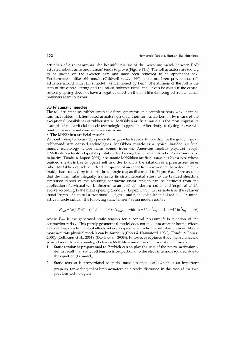
The roll actuator uses rubber stress as a force generator; in a complementary way, it can be said that rubber inflation-based actuators generate their contractile tension by means of the exceptional possibilities of rubber strain. McKibben artificial muscle is the most impressive example of this artificial muscle technological approach. After firstly analysing it , we will briefly discuss recent competitive approaches. a. The McKibben artificial muscle Without trying to accurately specify its origin which seems to lose itself in the golden age of rubber-industry derived technologies, McKibben muscle is a typical braided artificial muscle technology whose name comes from the American nuclear physicist Joseph L.McKibben who developed its prototype for bracing handicapped hands. As we have tried to justify (Tondu & Lopez, 2000), pneumatic McKibben artificial muscle is like a tyre whose braided sheath is free to open itself in order to allow the inflation of a pressurized inner tube. McKibben muscle is indeed composed of an inner tube surrounded by a double helix
braid, characterized by its initial braid angle (α0) as illustrated in Figure 6.a. If we assume that the inner tube integrally transmits its circumferential stress to the braided sheath, a simplified model of the resulting contractile linear tension can be deduced from the application of a virtual works theorem to an ideal cylinder the radius and length of which evolve according to the braid opening (Tondu & Lopez, 1995). Let us note l0 as the cylinder initial length – i.e. initial active muscle length – and r0 the cylinder initial radius – i.e. initial active muscle radius. The following static tension/strain model results :
02
02
max22
0 sin1/bandtan3/a with 0],)1([)( ααεεεπ ==≤≤−−= baPrFstat (6)
where Fstat is the generated static tension for a control pressure P in function of the
contraction ratio ε. This purely geometrical model does not take into account bound effects as force lose due to material effects whose major one is friction braid fibre on braid fibre – more accurate physical models can be found in (Chou & Hannaford, 1996), (Tondu & Lopez, 2000), (Colbrunn et al., 2001), (Davis et al., 2003)). It however captures three main characters which found the static analogy between McKibben muscle and natural skeletal muscle : 1. Static tension is proportional to P which can so play the part of the neural activation u
(let us recall that static roll tension is proportional to the electric tension squared due to the equation (1) model);
2. Static tension is proportional to initial muscle section )(20rπ which is an important
property for scaling robot-limb actuators as already discussed in the case of the two previous technologies;
Artificial Muscles for Humanoid Robots 103
3. Static tension continuously decreases when contraction ratio ε increases making the actuator a true contractile actuator as opposed to roll actuator.
(a)
(b) (c)
Figure 6. Pneumatic artificial muscle based on the use of a structure guiding the inflation of a elastomer chamber, (a) external structure case: operation principle of the McKibben muscle (see text), (b) internal structure case: longitudinal fibres included in a silicone tube (from (Saga et al., 2005) , see also (Nakamura et al., 2003)) – this type of muscle is as ‘old’ as McKibben muscle (Matsushita, 1968) -(c) Typical membrane case : pleated muscle (from (Daerden & Lefeber, 2001)) (see text)
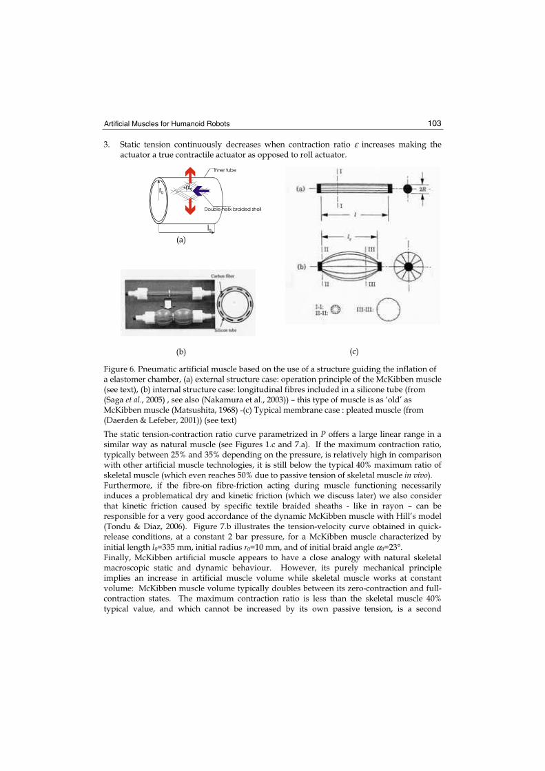
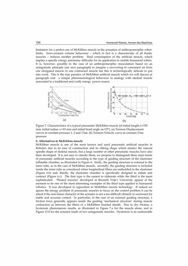
The static tension-contraction ratio curve parametrized in P offers a large linear range in a similar way as natural muscle (see Figures 1.c and 7.a). If the maximum contraction ratio, typically between 25% and 35% depending on the pressure, is relatively high in comparison with other artificial muscle technologies, it is still below the typical 40% maximum ratio of skeletal muscle (which even reaches 50% due to passive tension of skeletal muscle in vivo). Furthermore, if the fibre-on fibre-friction acting during muscle functioning necessarily induces a problematical dry and kinetic friction (which we discuss later) we also consider that kinetic friction caused by specific textile braided sheaths - like in rayon – can be responsible for a very good accordance of the dynamic McKibben muscle with Hill’s model (Tondu & Diaz, 2006). Figure 7.b illustrates the tension-velocity curve obtained in quick-release conditions, at a constant 2 bar pressure, for a McKibben muscle characterized by
initial length l0=335 mm, initial radius r0=10 mm, and of initial braid angle α0=23°. Finally, McKibben artificial muscle appears to have a close analogy with natural skeletal macroscopic static and dynamic behaviour. However, its purely mechanical principle implies an increase in artificial muscle volume while skeletal muscle works at constant volume: McKibben muscle volume typically doubles between its zero-contraction and full-contraction states. The maximum contraction ratio is less than the skeletal muscle 40% typical value, and which cannot be increased by its own passive tension, is a second
Double-helix braided shell
Inner tube
Humanoid Robots, Human-like Machines 104
limitation for a perfect use of McKibben muscle in the actuation of anthropomorphic robot-limbs. Non-constant volume behaviour – which in fact is a characteristic of all fluidic muscles – induces another problem: fluid consumption of the artificial muscle, which implies a specific energy autonomy difficulty for its application to mobile humanoid robots. It is, however, possible in the case of an anthropomorphic musculature based on an antagonistic principle (see next paragraph) to imagine a recovering of consumed air from one elongated muscle to one contracted muscle but this is technologically delicate to put into work. This is the true paradox of McKibben artificial muscle which we will discuss at paragraph end: a unique phenomenological behaviour in analogy with skeletal muscle associated to a traditional and costly energy power source.
(a) (b)
Figure 7. Characteristics of a typical pneumatic McKibben muscle (of initial length l0=335
mm, initial radius r0=10 mm and initial braid angle α0=23°), (a) Tension-Displacement curves at constant pressure 1, 2 and 3 bar, (b) Tension-Velocity curve at constant 2 bar pressure
b. Alternatives to McKibben muscle McKibben muscle is one of the most known and used pneumatic artificial muscles in Robotics due to its ease of construction and its oblong shape which mimics the natural spindle shape of skeletal muscle, but a large number of other pneumatic muscles have also been developed. It is not easy to classify them; we propose to distinguish three main kinds of pneumatic artificial muscles according to the type of guiding structure of the elastomer inflatable chamber, as illustrated in Figure 6: firstly, the guiding structure is external to the inner tube, as in the case of McKibben muscle; secondly, the guiding structure is included inside the inner tube as considered when longitudinal fibres are embedded in the elastomer (Figure 6.b) and, thirdly, the elastomer chamber is specifically designed to inflate and contract (Figure 6.c). The first type is the easiest to elaborate while the third is the most sophisticated. ‘Pleated muscles’ developed at Brussels Vrije’s University appear at the moment to be one of the most interesting examples of the third type applied to humanoid robotics. It was developed in opposition to McKibben muscle technology. If indeed we ignore the energy problem of pneumatic muscles to focus on the control problem it can be asked if the non-linear character of the actuator is not a too-difficult obstacle to surmount for stable and accurate control. In particular, in the case of an external guiding structure, a friction force generally appears inside the guiding ‘mechanical structure’ during muscle contraction as between the fibres of a McKibben braided sheath. Due to dry friction, a hysteresis phenomenon results, as illustrated in Figure 7.a for the muscle alone, and in Figure 15.b for the actuator made of two antagonistic muscles. Hysteresis is an undesirable
M
usc
le m
axi
mum
sho
rte
nin
g v
elo
city
(c
m/s
)
Load (kg)
Hill model : (F +15)V=(55- )11.5Hill FHill
0 0.05 0.1 0.15 0.2 0.25 0.30
20
40
60
80
100
Contraction ratio (%)
Sta
tic fo
rce
(d
N)
3 bar
2 bar
1 bar
Artificial Muscles for Humanoid Robots 105
non-linear effect; as will be analysed in the next paragraph; it is not, in our opinion, the major drawback to a robust control of anthropomorphic limbs actuated by artificial muscles. However, an artificial muscle without hysteresis is obviously a progress in the field; this is the case for the ‘pleated muscle’ which in the absence of any external braid rubbing against it, avoids the phenomenon. The ‘pleated muscle’ is a ‘cylindrical membrane of high stiffness and high flexibility [folded] along its cylindrical axis like accordion bellows’ (Daerden & Lefeber, 2001). When pressurized, inflation happens by unfolding and the artificial muscle shortens and bulges. As illustrated in Figure 12.a, static force characteristics – except for hysteresis – is globally similar to that of McKibben muscle, with a maximum contraction less dependent on pressure. The counterpart of braided sheath elimination is, however, a more complex geometrical shape of the artificial muscle (whereas the McKibben muscle globally keeps a cylindrical shape), pleated muscle offers a contracted complex ‘flower’-like shape). What results, firstly, is an increase in the maximum muscle section which, at the same generated stress, can really be higher than that of McKibben muscle and which induces mechanical integration difficulties (see next paragraph). Secondly, muscle shape geometrical complexity implies a more complex mathematical model of muscle inflation. The three fundamental properties exhibited by McKibben muscle also appear present in pleated muscle technology, but in comparison to McKibben muscle no simplified corresponding model can be deduced. The following static model is indeed proposed (Daerden & Lefeber, 2001) :
),/,( 0020 arlfPlFstat ε= (7)
where 0l is the initial active length, ε the contraction ratio, 0r the initial muscle radius, a is a
parameter depending on the Young modulus of the membrane elastomer and f is a dimensionless force function for which no closed form seems easy to exhibit (Daerden & Lefeber, 2001). Furthermore, the concordance of the force-velocity curve with Hill’s model has not yet been established. Lastly, it is important to note that ‘pleated’ artificial muscle can have a more limited lifespan than external guiding structure muscles due to the stress imposed to the membrane. As mentioned by Verrelst, the first generation pleated pneumatic artificial muscle has a limited lifespan due to the overlap used to make a cylindrical pleated membrane. The proposed second generation has a 400 000 cycle life but induces a complex mathematical model (Verrelst et al., 2006). In conclusion, the current field of available artificial muscles for humanoid robots is paradoxical: on the one hand, electroactive polymer-based roll actuators, although very promising, do not yet have sufficient power-to-volume to be embedded in robot-limbs and to actuate them; on the other hand, purely mechanical pneumatic artificial muscles appear to be at present the most biomimetic of muscles, although their energy mode is questionable. This paradoxical situation can, however, be settled in the following manner: even if given up in the future in favour of EAP-based muscles or other bio-inspired artificial muscles, fluidic artificial muscles, in our opinion, tackle the difficult question of mechanical integration and control of anthropomorphic limbs actuated by biomimetic artificial muscles, as considered in the two next paragraphs.
Humanoid Robots, Human-like Machines 106
4. Specific design of anthropomorphic limbs actuated with skeletal artificial muscles
4.1 Antagonistic muscle revolute actuator
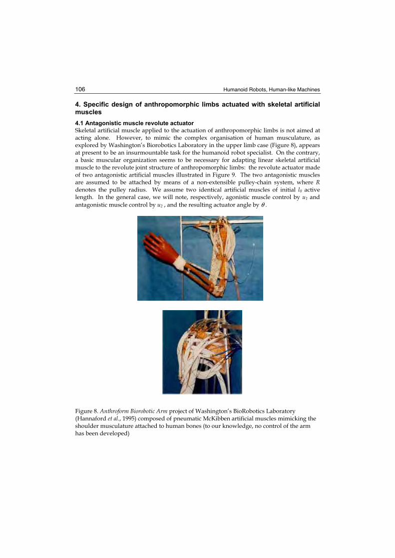
Skeletal artificial muscle applied to the actuation of anthropomorphic limbs is not aimed at acting alone. However, to mimic the complex organisation of human musculature, as explored by Washington’s Biorobotics Laboratory in the upper limb case (Figure 8), appears at present to be an insurmountable task for the humanoid robot specialist. On the contrary, a basic muscular organization seems to be necessary for adapting linear skeletal artificial muscle to the revolute joint structure of anthropomorphic limbs: the revolute actuator made of two antagonistic artificial muscles illustrated in Figure 9. The two antagonistic muscles are assumed to be attached by means of a non-extensible pulley-chain system, where Rdenotes the pulley radius. We assume two identical artificial muscles of initial l0 active length. In the general case, we will note, respectively, agonistic muscle control by u1 and
antagonistic muscle control by u2 , and the resulting actuator angle by θ .
Figure 8. Anthroform Biorobotic Arm project of Washington’s BioRobotics Laboratory (Hannaford et al., 1995) composed of pneumatic McKibben artificial muscles mimicking the shoulder musculature attached to human bones (to our knowledge, no control of the arm has been developed)
Artificial Muscles for Humanoid Robots 107
(a) (b)
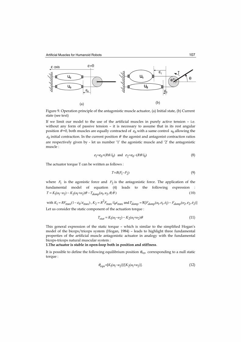
Figure 9. Operation principle of the antagonistic muscle actuator, (a) Initial state, (b) Current state (see text)
If we limit our model to the use of the artificial muscles in purely active tension – i.e. without any form of passive tension – it is necessary to assume that in its rest angular
position θ =0, both muscles are equally contracted of 0ε with a same control 0u allowing the
0ε initial contraction. In the current position θ the agonist and antagonist contraction ratios
are respectively given by - let us number ‘1’ the agonistic muscle and ‘2’ the antagonistic muscle :
)/(and)/( 002001 lRlR θεεθεε −=+= (8)
The actuator torque T can be written as follows :
)( 21 FFRT −= (9)
where 1F is the agonistic force and 2F is the antagonistic force. The application of the
fundamental model of equation (4) leads to the following expression :
)],,(),,(R[and/,)/1(with
(10)),,,()()(
222111max0max2
2max0max1
21212211
εεεεεεε
θθθ
uFuFTlFRKRFK
uuTuuKuuKT
dampdampdamp
damp
−==−=
−+−−=
Let us consider the static component of the actuation torque :
θ)()( 212211 uuKuuKTstat +−−= (11)
This general expression of the static torque – which is similar to the simplified Hogan’s model of the biceps/triceps system (Hogan, 1984) – leads to highlight three fundamental properties of the artificial muscle antagonistic actuator in analogy with the fundamental biceps-triceps natural muscular system : 1.The actuator is stable in open-loop both in position and stiffness.
It is possible to define the following equilibrium position θequ corresponding to a null static torque :
)].(/[)]([ 212211 uuKuuKequ +−=θ (12)
ε=0ε axis
θT
Humanoid Robots, Human-like Machines 108
In this equilibrium position, the stiffness actuator S defined as follows :
)( 212 uuKS += (13)
can be changed by multiplying the u1 and u2 inputs by a same factor, although the
conditions 11≤u and 12≤u are verified.
2. The actuator is both a torque and a stiffness generator.
The previous property is the consequence of the fact that the actuator can be considered as a double input-output system whose (u1, u2) are the inputs and (Tstat, S) are the outputs defined as follows :
−−
++=⇔
−−−=
S
T
KKK
KKK
KKu
u
u
u
KK
KKKK
S
T statstat
21
212
212
212
1
2
1
22
2121
θ
θθθ (14)
We will use this double nature of the antagonistic artificial muscle actuator in next control paragraph.
3. The maximum actuator torque decreases continuously from an actuator angle limit to the other one.
Let us assume that each actuator muscle can fully contract of its εmax maximum contraction ratio. If the two muscles are identical, the two actuator angle limits can be defined as follows:
]/)(,/)([],[ 00max00maxmaxmin RlRl εεεεθθ −+−−= (15)
For every actuator angle θ belonging to this range, we get the following expression of the maximum torque, corresponding to a maximum control of the agonistic muscle (u1=1) and a null control of the antagonistic muscle (u2=0) :
θθ 21max )( KKT −= (16)
The maximum torque decreases in consequence from θmin to θmax with the 2K− slope. In
comparison with classical actuators, the presence of the restoring torque term ‘ θ)( 212 uuK +− ’
gives to the biomimetic actuator a natural compliance which can be actively controlled independently from the actuator position. However, a drawback results that is analysed in next paragraph: angular position actuator torque dependence induces a specific sensitivity of the actuator on gravity.
4.2 Gravity test with artificial muscle actuator
The first request for any actuation mode of a robot-limb is its ability to move each link all along the desired joint range. As for humans, the most important resistance of humanoid robot links is gravity. We consider that testing the ability of an artificial muscle actuator embedded on the kinematic chain to directly drive joints of a human size (in volume and weight) robot-limb could be a more rigorous test than the ‘arm wrestling contest’ organized by NASA (see the rules for the wrestling match between EAP actuated robotic arms and human on the website http://armwrestling.com/rulesandregulations.html) to test EAP-roll actuator performances, illustrated in Figure 11.b. In particular this ‘gravity test’ is made
Artificial Muscles for Humanoid Robots 109
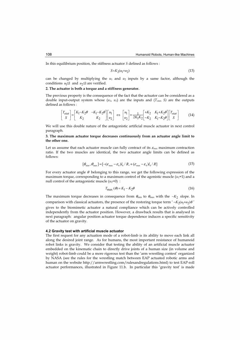
difficult by the specific nature of the artificial muscle actuator highlighted in the previous paragraph. Let us consider the case of a single actuator driving a link as illustrated in Figure 10.a: the two antagonistic muscles represent, for example, the biceps-triceps system actuating the arm placed in a vertical position, the considered joint the elbow flexion-extension and the link the set forearm + hand. Let us further consider a total joint range of 180° imposing the actuator zero-position when the moving link is at the horizontal position. If the positive direction corresponds to the flexion movement, gravity torque is always resistive and can be written as follows : cosθmglTgravity −= , as illustrated in Figure 10.a. The
maximum available actuator torque is given by equation (16) and subsequently the total torque can be deduced as simulated in Figure 10.b. It appears that in the [-90°,+90°] joint range, the total torque becomes minimum, and it is clear that if this minimum is negative, a special point results where the total torque becomes null and as a consequence, the actuator is no longer able to lift the link. In a more general manner, the gravity test appears as a quasi-static test which consists of checking that the total static joint torque keeps strictly positive on the considered actuator joint range. It is interesting to note that a load in hand can easily put the test in difficulty. The two shoulder movements in flexion-extension and abduction-adduction are particularly concerned by this test: the situation is analogous to the one illustrated in Figure 10 but now the link to lift represents the whole upper limb with a possible load in hand. Consequently, the actuation of a robot shoulder by artificial muscles can necessitate very strong muscles, notably if the flexion-extension and abduction-adduction movements are, respectively, performed by only one pair of antagonistic muscles. For example, the robot shoulder of our 7R anthropomorphic of the same size as a human upper limb - but of double weight – illustrated in Figure 13.b is actuated by McKibben pneumatic muscles able to develop more than 500 dN under a 5 bar pressure. Generally, this difficulty in actuating a human-like shoulder by artificial muscles reveals the need for future humanoid robots to mimic not only the antagonistic muscle principle, but also natural muscular system redundancy, as attempted in Figure 8.
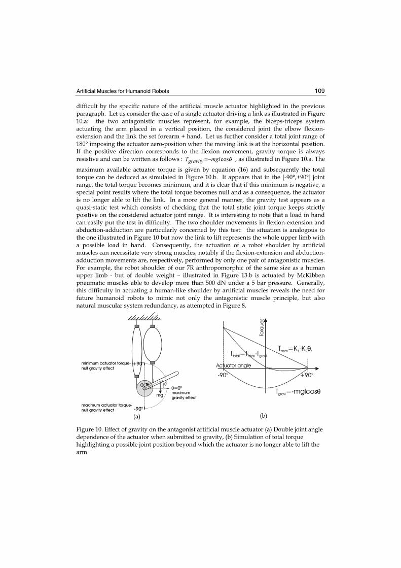
(a) (b)
Figure 10. Effect of gravity on the antagonist artificial muscle actuator (a) Double joint angle dependence of the actuator when submitted to gravity, (b) Simulation of total torque highlighting a possible joint position beyond which the actuator is no longer able to lift the arm
maximum
gravity effect
minimum actuator torque-
null gravity effect+90°
-90°maximum actuator torque-
null gravity effect
mg
l
-90° +90°
T =-mglcosgravi θ
T =K -Kmax 1 2 rθT =T -Ttotal max gravi
Actuator angle
Torq
ue
s

Humanoid Robots, Human-like Machines 110
4.3 Integrating artificial muscles to anthropomorphic kinematic structures
The integration of artificial muscle into a humanoid robot whose limbs, size and weight are those of a medium sized human being induces specific constraints in actuator joint range, actuator power-to-volume, actuator power-to-mass, and robot energy range. If we leave the latter constraint which depends on the development of embedded batteries, the first three are direct consequences of artificial muscle technology applied on a human-scale robot. Power-to-mass is generally not a difficulty due to the low mass density of polymer-type materials, but generating both actuator ‘joint range’ and ‘power-to-volume’ similar to skeletal muscle ones is a major challenge because of the difficulty in designing compact artificial muscle working at a constant volume as a skeletal muscle does. As already mentioned, EAP-roll actuators cannot yet fully satisfy these constraints. Pneumatic muscles are at present the most able ones within sight of these two criteria. This is the reason why all current anthropomorphic limbs actuated by artificial muscles use pneumatic ones, but it is important to emphasize that, even in the case of this technology choice, the integration of artificial muscle actuator to anthropomorphic robot-limbs is made difficult by their limited biomimetic behaviour :
• the global cylindrical shape of the McKibben pneumatic muscle helps its integration in spite of its volume increase, but its relatively limited maximum contraction is a real drawback for the actuation of large joint movements: in particular, flexion/extension and abduction/adduction human shoulder movements are particularly difficult to mimic with artificial muscles, without using excessively long artificial muscles; our 7R robot prototype, illustrated in Figure 13.b, has shoulder joint ranges equal to [0,+180°] in abduction-adduction and to [0,+100°] in flexion-extension thanks to transmission gears amplifying the actuator angular motion at a 1.5 ratio in order to limit shoulder width to about 35 cm (Tondu et al., 2005). In the case of the Shadow Robot illustrated in Figure 13.a, it can be noted that the shoulder muscles are placed vertically in the robot waist, which is not adapted to humanoid architecture;
• the pleated muscles offer the advantage of high maximum contraction ratios weakly dependent on the control pressure, but its bulkiness when the muscle is contracted prevents the putting into parallel of two antagonistic muscles: as illustrated in Figure 12.b, the two pleated muscles have to be shifted in order to allow the antagonistic muscle actuator to get working which reduces the actuator range. Lucy robot (Verrelst et al. 2005), illustrated in Figure 12.c, is a successful application of pleated muscle actuation, but it can be asked if it is as well adapted to actuation by upper limbs necessitating larger joint ranges.
Analysis of these two points emphasizes the difficulty of actuating anthropomorphic robot-limbs by artificial muscles: the global ‘optimal’ character of the human muscular-skeletal system makes all attempts at mimicking the system difficult if one analogical term is missing.
Artificial Muscles for Humanoid Robots 111
(a) (b)
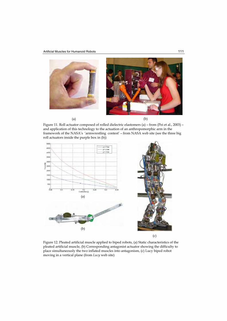
Figure 11. Roll actuator composed of rolled dielectric elastomers (a) – from (Pei et al., 2003) – and application of this technology to the actuation of an anthropomorphic arm in the framework of the NASA’s ‘armwrestling contest’ – from NASA web site (see the three big roll actuators inside the purple box in (b))
(a)
(b)
(c)
Figure 12. Pleated artificial muscle applied to biped robots, (a) Static characteristics of the pleated artificial muscle, (b) Corresponding antagonist actuator showing the difficulty to place simultaneously the two inflated muscles into antagonism, (c) Lucy biped robot moving in a vertical plane (from Lucy web site)
Humanoid Robots, Human-like Machines 112
(a) (b)
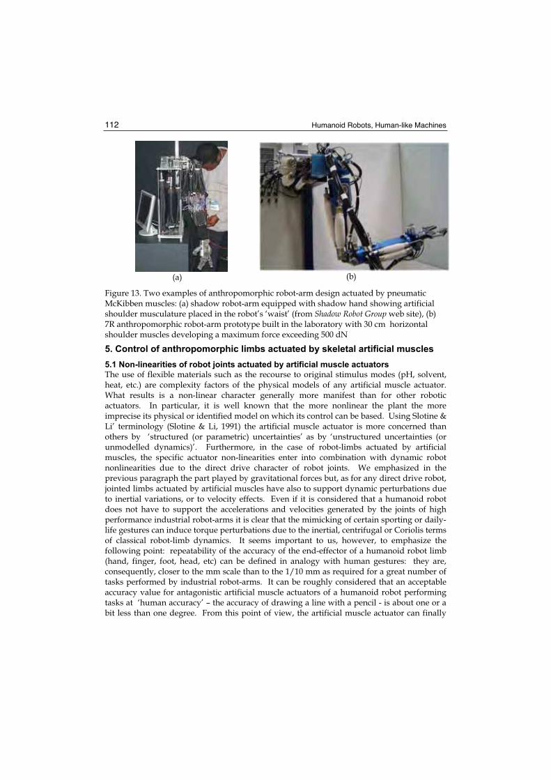
Figure 13. Two examples of anthropomorphic robot-arm design actuated by pneumatic McKibben muscles: (a) shadow robot-arm equipped with shadow hand showing artificial shoulder musculature placed in the robot’s ‘waist’ (from Shadow Robot Group web site), (b) 7R anthropomorphic robot-arm prototype built in the laboratory with 30 cm horizontal shoulder muscles developing a maximum force exceeding 500 dN
5. Control of anthropomorphic limbs actuated by skeletal artificial muscles
5.1 Non-linearities of robot joints actuated by artificial muscle actuators
The use of flexible materials such as the recourse to original stimulus modes (pH, solvent, heat, etc.) are complexity factors of the physical models of any artificial muscle actuator. What results is a non-linear character generally more manifest than for other robotic actuators. In particular, it is well known that the more nonlinear the plant the more imprecise its physical or identified model on which its control can be based. Using Slotine & Li’ terminology (Slotine & Li, 1991) the artificial muscle actuator is more concerned than others by ‘structured (or parametric) uncertainties’ as by ‘unstructured uncertainties (or unmodelled dynamics)’. Furthermore, in the case of robot-limbs actuated by artificial muscles, the specific actuator non-linearities enter into combination with dynamic robot nonlinearities due to the direct drive character of robot joints. We emphasized in the previous paragraph the part played by gravitational forces but, as for any direct drive robot, jointed limbs actuated by artificial muscles have also to support dynamic perturbations due to inertial variations, or to velocity effects. Even if it is considered that a humanoid robot does not have to support the accelerations and velocities generated by the joints of high performance industrial robot-arms it is clear that the mimicking of certain sporting or daily-life gestures can induce torque perturbations due to the inertial, centrifugal or Coriolis terms of classical robot-limb dynamics. It seems important to us, however, to emphasize the following point: repeatability of the accuracy of the end-effector of a humanoid robot limb (hand, finger, foot, head, etc) can be defined in analogy with human gestures: they are, consequently, closer to the mm scale than to the 1/10 mm as required for a great number of tasks performed by industrial robot-arms. It can be roughly considered that an acceptable accuracy value for antagonistic artificial muscle actuators of a humanoid robot performing tasks at ‘human accuracy’ – the accuracy of drawing a line with a pencil - is about one or a bit less than one degree. From this point of view, the artificial muscle actuator can finally
Artificial Muscles for Humanoid Robots 113
appear more adapted to humanoid robots mimicking human gestures than ultra-accurate, but non naturally compliant electric motors. This is true provided there is the possibility of being able to design a control mode of the artificial muscle as effective as the one resulting from the complex and badly known human movement learning principles. In the next paragraph we analyse some current or envisaged control modes of artificial muscle robot actuators: all results mentioned were obtained on pneumatic artificial muscles which as already emphasized, seem the only ones to have been actually tested on human-scale robot-limbs.
5.2. Single-variable position control
The antagonistic artificial muscle has been previously defined as a multiple input-multiple output (MIMO) system. Since the first target of the actuator control is a control position, it can be asked if it is possible to simplify the actuator functioning in order to consider it as a single input-single output (SISO) system whose output is reduced to the angular position. A simple way of doing this, initiated in our opinion by Bridgestone (Bridgestone, 1987),
consists of a symmetrical control of agonist and antagonist muscles in the form of a ‘Δu’
input control added to the initial ‘u0’ to control the agonist when antagonist control of ‘Δu’decreases , as follows :
uuuuuu Δ−=Δ+= and 0201 (17)
The new torque expression results :
),,(22 021 θθuTuKuKT damp Δ−−Δ= (18)
The relationship between input Δu and equilibrium position θequ is now
uuKKequ Δ= )/( 021θ and actuator stiffness is now constant : 022 uKS= . The artificial muscle
actuator can now be considered as a revolute actuator to which a linear or non-linear control approach can be applied. Furthermore, its open-loop position stability gives an original opportunity for facilitating joint control: it is indeed possible to identify the angular joint and to use the identification result as a feedforward term. We have demonstrated the advantage of this approach in controlling a 2R-SCARA-type robot actuated by four similar pneumatic McKibben muscles (Tondu & Lopez, 2000). In the framework of humanoid robotics, this kinematic architecture corresponds to a arm-forearm set performing horizontal shoulder and/or elbow flexion-extension movements – without the consequent gravity effect. In this case, a second-order linear model of the form :
)()/()( 212
pUapapbp Δ++=θ (19)
appears to be very satisfactory to identify the step response. Physically, according to the torque model of equation (18), and assuming that the joint drives a constant inertia (forearm inertia or in the case of the shoulder joint, maximum forearm + arm inertia), the term ‘a2 ‘ can be interpreted as a specific actuator stiffness and ‘a1’ as a linear viscous term approaching complex actuator damping. A typical linear controller illustrated in Figure 14.a results where the identified model is used as a feedforward term in association with a PID linear feedback, for example.
Humanoid Robots, Human-like Machines 114
(a) (b)
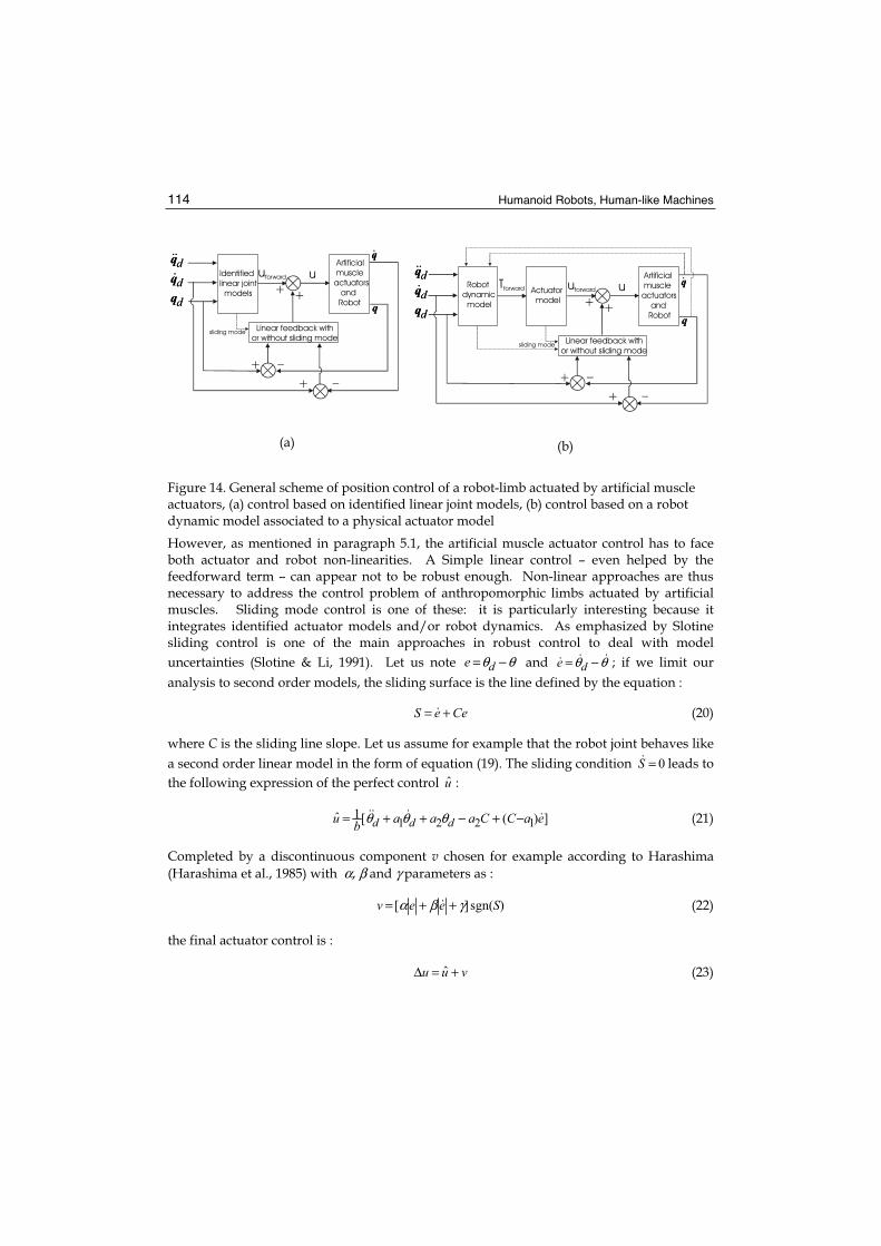
Figure 14. General scheme of position control of a robot-limb actuated by artificial muscle actuators, (a) control based on identified linear joint models, (b) control based on a robot dynamic model associated to a physical actuator model
However, as mentioned in paragraph 5.1, the artificial muscle actuator control has to face both actuator and robot non-linearities. A Simple linear control – even helped by the feedforward term – can appear not to be robust enough. Non-linear approaches are thus necessary to address the control problem of anthropomorphic limbs actuated by artificial muscles. Sliding mode control is one of these: it is particularly interesting because it integrates identified actuator models and/or robot dynamics. As emphasized by Slotine sliding control is one of the main approaches in robust control to deal with model
uncertainties (Slotine & Li, 1991). Let us note θθ −= de and θθ −= de ; if we limit our
analysis to second order models, the sliding surface is the line defined by the equation :
CeeS += (20)
where C is the sliding line slope. Let us assume for example that the robot joint behaves like
a second order linear model in the form of equation (19). The sliding condition 0=S leads to
the following expression of the perfect control u :
])([1ˆ 1221 eaCCaaab
u ddd −+−++= θθθ (21)
Completed by a discontinuous component v chosen for example according to Harashima
(Harashima et al., 1985) with α, β and γ parameters as :
)sgn(][ Seev γβα ++= (22)
the final actuator control is :
vuu ˆ +=Δ (23)
d
d
d
q
q
q q
q
Identifiedlinear joint models
Artificial muscleactuators and Robotd
d
d
q
q
q
Linear feedback withor without sliding mode
uuforward
+
+
_
q
_
++
sliding mode
d
d
d
q
q
q q
q
Robotdynamic model
Actuator model
Artificial muscleactuators and Robotd
d
d
q
q
q
Linear feedback withor without sliding mode
uuforwardTforward
+
+
_
_
++
sliding mode
q
Artificial Muscles for Humanoid Robots 115
(a) (b)
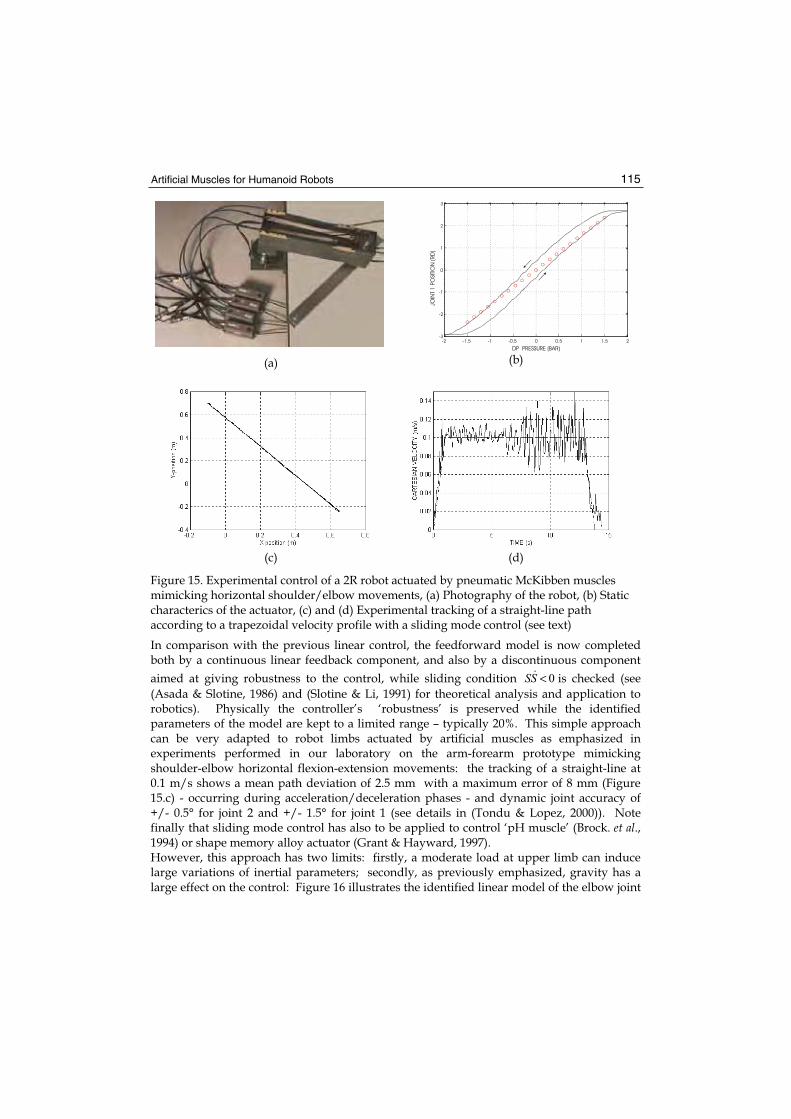
(c) (d)
Figure 15. Experimental control of a 2R robot actuated by pneumatic McKibben muscles mimicking horizontal shoulder/elbow movements, (a) Photography of the robot, (b) Static characterics of the actuator, (c) and (d) Experimental tracking of a straight-line path according to a trapezoidal velocity profile with a sliding mode control (see text)
In comparison with the previous linear control, the feedforward model is now completed both by a continuous linear feedback component, and also by a discontinuous component
aimed at giving robustness to the control, while sliding condition 0<SS is checked (see
(Asada & Slotine, 1986) and (Slotine & Li, 1991) for theoretical analysis and application to robotics). Physically the controller’s ‘robustness’ is preserved while the identified parameters of the model are kept to a limited range – typically 20%. This simple approach can be very adapted to robot limbs actuated by artificial muscles as emphasized in experiments performed in our laboratory on the arm-forearm prototype mimicking shoulder-elbow horizontal flexion-extension movements: the tracking of a straight-line at 0.1 m/s shows a mean path deviation of 2.5 mm with a maximum error of 8 mm (Figure 15.c) - occurring during acceleration/deceleration phases - and dynamic joint accuracy of +/- 0.5° for joint 2 and +/- 1.5° for joint 1 (see details in (Tondu & Lopez, 2000)). Note finally that sliding mode control has also to be applied to control ‘pH muscle’ (Brock. et al., 1994) or shape memory alloy actuator (Grant & Hayward, 1997). However, this approach has two limits: firstly, a moderate load at upper limb can induce large variations of inertial parameters; secondly, as previously emphasized, gravity has a large effect on the control: Figure 16 illustrates the identified linear model of the elbow joint
-2 -1.5 -1 -0.5 0 0.5 1 1.5 2-3
-2
-1
0
1
2
3
DP PRESSURE (BAR)
JOIN
T 1
PO
SITI
ON
(R
D)
Humanoid Robots, Human-like Machines 116
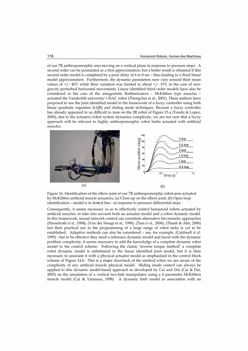
of our 7R anthropomorphic arm moving on a vertical plane in response to pressure steps. A second order can be postulated as a first approximation, but a better result is obtained if this second order model is completed by a pure delay of 6 to 8 ms – thus leading to a third linear model approximation. Furthermore, the dynamic parameters now vary around their mean values of +/- 40% while their variation was limited to about +/- 15% in the case of non-gravity perturbed horizontal movements. Linear identified third order models have also be considered in the case of the antagonistic Rubbertuators – McKibben type muscles – actuated the Vanderbilt university’s ISAC robot (Thongchai et al., 2001). These authors have proposed to use the joint identified model in the framework of a fuzzy controller using both linear quadratic regulator (LQR) and sliding mode techniques. Because a fuzzy controller has already appeared to us difficult to tune on the 2R robot of Figure 15.a (Tondu & Lopez, 2000), due to the actuator/robot system dynamics complexity, we are not sure that a fuzzy approach will be relevant to highly anthropomorphic robot limbs actuated with artificial muscles.
(a) (b)
Figure 16. Identification of the elbow joint of our 7R anthropomorphic robot-arm actuated by McKibben artificial muscle actuators, (a) Close-up on the elbow joint, (b) Open loop identification – model is in dotted line - in response to pressure differential steps
Consequently, it seems necessary so as to effectively control humanoid robots actuated by artificial muscles, to take into account both an actuator model and a robot dynamic model. In this framework, neural network control can constitute alternative bio-mimetic approaches (Hesselroth et al., 1994), (Van der Smagt et al., 1996), (Tian et al., 2004), (Thanh & Ahn, 2006) but their practical use in the programming of a large range of robot tasks is yet to be established. Adaptive methods can also be considered – see, for example, (Caldwell et al.1995) - but to be effective they need a reference dynamic model and faced with the dynamic problem complexity, it seems necessary to add the knowledge of a complete dynamic robot model to the control scheme. Following the classic ‘inverse torque method’ a complete robot dynamic model is substituted to the linear identified joint model, but it is then necessary to associate it with a physical actuator model as emphasized in the control block scheme of Figure 14.b. This is a major drawback of the method when we are aware of the complexity of any artificial muscle physical model. Sliding mode control can always be applied to this dynamic model-based approach as developed by Cai and Dai (Cai & Dai, 2003) on the simulation of a vertical two-link manipulator using a 4 parameter McKibben muscle model (Cai & Yamaura, 1998). A dynamic limb model in association with an
0 0.5 1 1.50
20
40
60
80
100
120
Time (s)
Elb
ow
po
sitio
n (d
eg
)
0.5 bar
1 bar
1.5 bar
2 bar
2.5 bar
3 bar
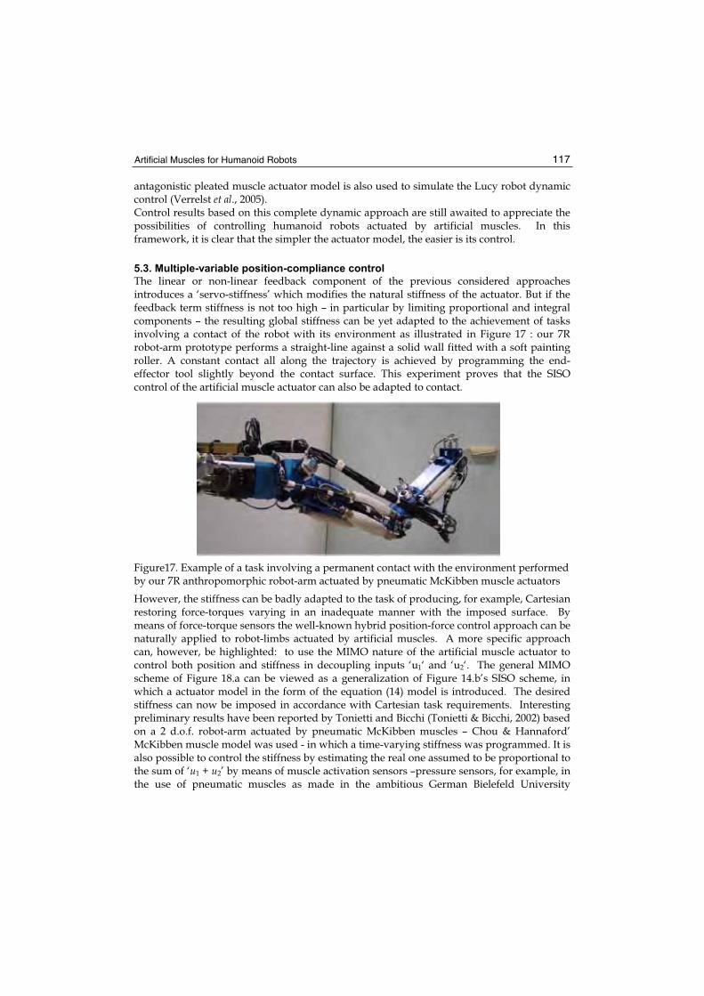
Artificial Muscles for Humanoid Robots 117
antagonistic pleated muscle actuator model is also used to simulate the Lucy robot dynamic control (Verrelst et al., 2005). Control results based on this complete dynamic approach are still awaited to appreciate the possibilities of controlling humanoid robots actuated by artificial muscles. In this framework, it is clear that the simpler the actuator model, the easier is its control.
5.3. Multiple-variable position-compliance control
The linear or non-linear feedback component of the previous considered approaches introduces a ‘servo-stiffness’ which modifies the natural stiffness of the actuator. But if the feedback term stiffness is not too high – in particular by limiting proportional and integral components – the resulting global stiffness can be yet adapted to the achievement of tasks involving a contact of the robot with its environment as illustrated in Figure 17 : our 7R robot-arm prototype performs a straight-line against a solid wall fitted with a soft painting roller. A constant contact all along the trajectory is achieved by programming the end-effector tool slightly beyond the contact surface. This experiment proves that the SISO control of the artificial muscle actuator can also be adapted to contact.
Figure17. Example of a task involving a permanent contact with the environment performed by our 7R anthropomorphic robot-arm actuated by pneumatic McKibben muscle actuators
However, the stiffness can be badly adapted to the task of producing, for example, Cartesian restoring force-torques varying in an inadequate manner with the imposed surface. By means of force-torque sensors the well-known hybrid position-force control approach can be naturally applied to robot-limbs actuated by artificial muscles. A more specific approach can, however, be highlighted: to use the MIMO nature of the artificial muscle actuator to control both position and stiffness in decoupling inputs ‘u1‘ and ‘u2‘. The general MIMO scheme of Figure 18.a can be viewed as a generalization of Figure 14.b’s SISO scheme, in which a actuator model in the form of the equation (14) model is introduced. The desired stiffness can now be imposed in accordance with Cartesian task requirements. Interesting preliminary results have been reported by Tonietti and Bicchi (Tonietti & Bicchi, 2002) based on a 2 d.o.f. robot-arm actuated by pneumatic McKibben muscles – Chou & Hannaford’ McKibben muscle model was used - in which a time-varying stiffness was programmed. It is also possible to control the stiffness by estimating the real one assumed to be proportional to the sum of ‘u1 + u2’ by means of muscle activation sensors –pressure sensors, for example, in the use of pneumatic muscles as made in the ambitious German Bielefeld University
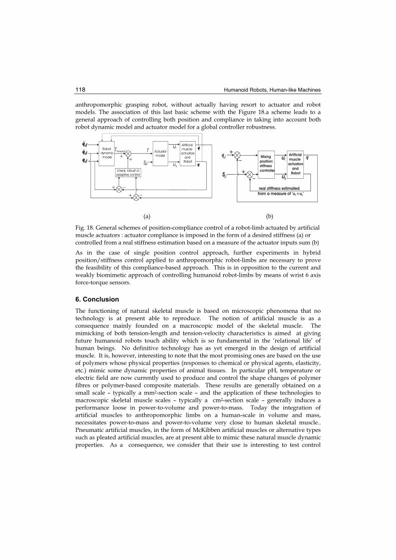
Humanoid Robots, Human-like Machines 118
anthropomorphic grasping robot, without actually having resort to actuator and robot models. The association of this last basic scheme with the Figure 18.a scheme leads to a general approach of controlling both position and compliance in taking into account both robot dynamic model and actuator model for a global controller robustness.
(a)
Mixingposition/stiffnesscontroller
Artificial muscleactuators and Robot
u
_
+
u
1
2Sd
+
real stiffness estimatedfrom a measure of ‘u +u ’1 2
qd _ q
(b)
Fig. 18. General schemes of position-compliance control of a robot-limb actuated by artificial muscle actuators : actuator compliance is imposed in the form of a desired stiffness (a) or controlled from a real stiffness estimation based on a measure of the actuator inputs sum (b)
As in the case of single position control approach, further experiments in hybrid position/stiffness control applied to anthropomorphic robot-limbs are necessary to prove the feasibility of this compliance-based approach. This is in opposition to the current and weakly biomimetic approach of controlling humanoid robot-limbs by means of wrist 6 axis force-torque sensors.
6. Conclusion
The functioning of natural skeletal muscle is based on microscopic phenomena that no technology is at present able to reproduce. The notion of artificial muscle is as a consequence mainly founded on a macroscopic model of the skeletal muscle. The mimicking of both tension-length and tension-velocity characteristics is aimed at giving future humanoid robots touch ability which is so fundamental in the ‘relational life’ of human beings. No definitive technology has as yet emerged in the design of artificial muscle. It is, however, interesting to note that the most promising ones are based on the use of polymers whose physical properties (responses to chemical or physical agents, elasticity, etc.) mimic some dynamic properties of animal tissues. In particular pH, temperature or electric field are now currently used to produce and control the shape changes of polymer fibres or polymer-based composite materials. These results are generally obtained on a small scale – typically a mm2-section scale – and the application of these technologies to macroscopic skeletal muscle scales – typically a cm2-section scale – generally induces a performance loose in power-to-volume and power-to-mass. Today the integration of artificial muscles to anthropomorphic limbs on a human-scale in volume and mass, necessitates power-to-mass and power-to-volume very close to human skeletal muscle.. Pneumatic artificial muscles, in the form of McKibben artificial muscles or alternative types such as pleated artificial muscles, are at present able to mimic these natural muscle dynamic properties. As a consequence, we consider that their use is interesting to test control
d
d
d
q
q
q
Robotdynamic model
Actuator model
Artificial muscleactuators and Robotd
d
d
q
q
q
Linear, robust or adaptive control
uTTforward
+
+
_
_
++
q
u
1
2Sd
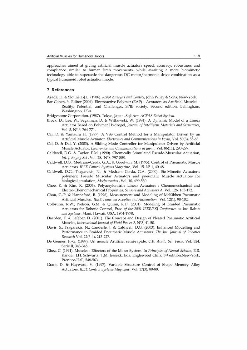
Artificial Muscles for Humanoid Robots 119
approaches aimed at giving artificial muscle actuators speed, accuracy, robustness and compliance similar to human limb movements, while awaiting a more biomimetic technology able to supersede the dangerous DC motor/harmonic drive combination as a typical humanoid robot actuation mode.
7. References
Asada, H. & Slotine J.-J.E. (1986). Robot Analysis and Control, John Wiley & Sons, New-York. Bar-Cohen, Y. Editor (2004). Electroactive Polymer (EAP) – Actuators as Artificial Muscles –
Reality, Potential, and Challenges, SPIE society, Second edition, Bellingham, Washington, USA.
Bridgestone Corporation. (1987). Tokyo, Japan, Soft Arm ACFAS Robot System.Brock, D.; Lee, W.; Segalman, D. & Witkowski, W. (1994). A Dynamic Model of a Linear
Actuator Based on Polymer Hydrogel, Journal of Intelligent Materials and Structures,Vol. 5, N° 6, 764-771.
Cai, D. & Yamaura H. (1997). A VSS Control Method for a Manipulator Driven by an Artificial Muscle Actuator. Electronics and Communications in Japan, Vol. 80(3), 55-63.
Cai, D. & Dai, Y. (2003). A Sliding Mode Controller for Manipulator Driven by Artificial Muscle Actuator. Electronics and Communications in Japan, Vol. 86(11), 290-297.
Caldwell, D.G. & Taylor, P.M. (1990). Chemically Stimulated Pseudo-Muscular Actuation, Int. J. Engng Sci , Vol. 28, N°8, 797-808.
Caldwell, D.G.; Medrano-Cerda, G.A.; & Goodwin, M. (1995). Control of Pneumatic Muscle Actuators. IEEE Control Systems Magazine , Vol. 15, N° 1, 40-48.
Caldwell, D.G.; Tsagarakis, N.; & Medrano-Cerda, G.A. (2000). Bio-Mimetic Actuators: polymeric Pseudo Muscular Actuators and pneumatic Muscle Actuators for biological emulation, Mechatronics , Vol. 10, 499-530.
Choe, K. & Kim, K. (2006). Polyacrylonitrile Linear Actuators : Chemomechanical and Electro-Chemomechanical Properties, Sensors and Actuators A, Vol. 126, 165-172.
Chou, C.-P. & Hannaford, B. (1996). Measurement and Modeling of McKibben Pneumatic Artificial Muscles. IEEE Trans. on Robotics and Automation , Vol. 12(1), 90-102.
Colbrunn, R.W.; Nelson, G.M. & Quinn, R.D. (2001). Modeling of Braided Pneumatic Actuators for Robotic Control, Proc. of the 2001 IEEE/RSJ Conference on Int. Robots and Systems, Maui, Hawaii, USA, 1964-1970.
Daerden, F. & Lefeber, D. (2001). The Concept and Design of Pleated Pneumatic Artificial Muscles, International Journal of Fluid Power 2, N°3, 41-50.
Davis, S.; Tsagarakis, N.; Canderle, J. & Caldwell, D.G. (2003). Enhanced Modelling and Performance in Braided Pneumatic Muscle Actuators. The Int. Journal of Robotics Research Vol. 22(3-4), 213-227.
De Gennes, P.-G. (1997). Un muscle Artificiel semi-rapide, C.R. Acad., Sci. Paris, Vol. 324, Serie II, 343-348.
Ghez, C. (1991). Muscles : Effectors of the Motor System. In Principles of Neural Science, E.R. Kandel, J.H. Schwartz, T.M. Jessekk, Eds. Englewood Cliffs, 3rd edition,New-York, Prentice-Hall, 548-563.
Grant, D. & Hayward, V. (1997). Variable Structure Control of Shape Memory Alloy Actuators, IEEE Control Systems Magazine, Vol. 17(3), 80-88.
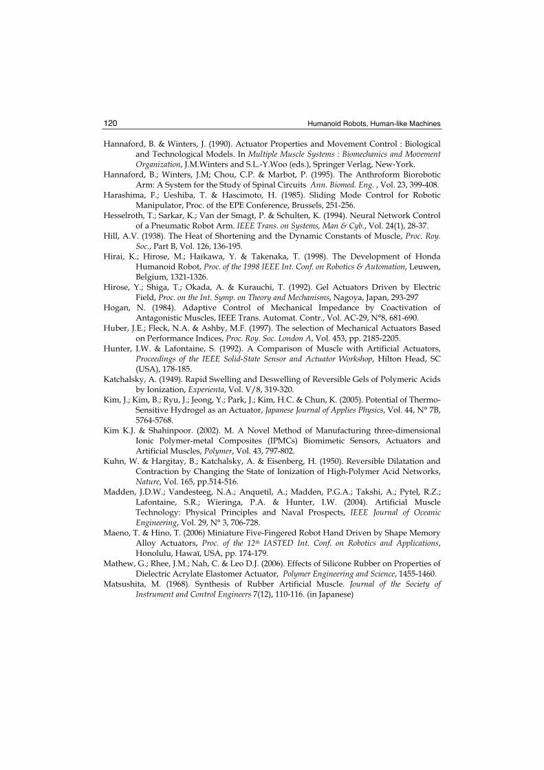
Humanoid Robots, Human-like Machines 120
Hannaford, B. & Winters, J. (1990). Actuator Properties and Movement Control : Biological and Technological Models. In Multiple Muscle Systems : Biomechanics and Movement Organization, J.M.Winters and S.L.-Y.Woo (eds.), Springer Verlag, New-York.
Hannaford, B.; Winters, J.M; Chou, C.P. & Marbot, P. (1995). The Anthroform Biorobotic Arm: A System for the Study of Spinal Circuits Ann. Biomed. Eng. , Vol. 23, 399-408.
Harashima, F.; Ueshiba, T. & Hascimoto, H. (1985). Sliding Mode Control for Robotic Manipulator, Proc. of the EPE Conference, Brussels, 251-256.
Hesselroth, T.; Sarkar, K.; Van der Smagt, P. & Schulten, K. (1994). Neural Network Control of a Pneumatic Robot Arm. IEEE Trans. on Systems, Man & Cyb., Vol. 24(1), 28-37.
Hill, A.V. (1938). The Heat of Shortening and the Dynamic Constants of Muscle, Proc. Roy. Soc., Part B, Vol. 126, 136-195.
Hirai, K.; Hirose, M.; Haikawa, Y. & Takenaka, T. (1998). The Development of Honda Humanoid Robot, Proc. of the 1998 IEEE Int. Conf. on Robotics & Automation, Leuwen, Belgium, 1321-1326.
Hirose, Y.; Shiga, T.; Okada, A. & Kurauchi, T. (1992). Gel Actuators Driven by Electric Field, Proc. on the Int. Symp. on Theory and Mechanisms, Nagoya, Japan, 293-297
Hogan, N. (1984). Adaptive Control of Mechanical Impedance by Coactivation of Antagonistic Muscles, IEEE Trans. Automat. Contr., Vol. AC-29, N°8, 681-690.
Huber, J.E.; Fleck, N.A. & Ashby, M.F. (1997). The selection of Mechanical Actuators Based on Performance Indices, Proc. Roy. Soc. London A, Vol. 453, pp. 2185-2205.
Hunter, I.W. & Lafontaine, S. (1992). A Comparison of Muscle with Artificial Actuators, Proceedings of the IEEE Solid-State Sensor and Actuator Workshop, Hilton Head, SC (USA), 178-185.
Katchalsky, A. (1949). Rapid Swelling and Deswelling of Reversible Gels of Polymeric Acids by Ionization, Experienta, Vol. V/8, 319-320.
Kim, J.; Kim, B.; Ryu, J.; Jeong, Y.; Park, J.; Kim, H.C. & Chun, K. (2005). Potential of Thermo-Sensitive Hydrogel as an Actuator, Japanese Journal of Applies Physics, Vol. 44, N° 7B, 5764-5768.
Kim K.J. & Shahinpoor. (2002). M. A Novel Method of Manufacturing three-dimensional Ionic Polymer-metal Composites (IPMCs) Biomimetic Sensors, Actuators and Artificial Muscles, Polymer, Vol. 43, 797-802.
Kuhn, W. & Hargitay, B.; Katchalsky, A. & Eisenberg, H. (1950). Reversible Dilatation and Contraction by Changing the State of Ionization of High-Polymer Acid Networks, Nature, Vol. 165, pp.514-516.
Madden, J.D.W.; Vandesteeg, N.A.; Anquetil, A.; Madden, P.G.A.; Takshi, A.; Pytel, R.Z.; Lafontaine, S.R.; Wieringa, P.A. & Hunter, I.W. (2004). Artificial Muscle Technology: Physical Principles and Naval Prospects, IEEE Journal of Oceanic Engineering, Vol. 29, N° 3, 706-728.
Maeno, T. & Hino, T. (2006) Miniature Five-Fingered Robot Hand Driven by Shape Memory Alloy Actuators, Proc. of the 12th IASTED Int. Conf. on Robotics and Applications,Honolulu, Hawaï, USA, pp. 174-179.
Mathew, G.; Rhee, J.M.; Nah, C. & Leo D.J. (2006). Effects of Silicone Rubber on Properties of Dielectric Acrylate Elastomer Actuator, Polymer Engineering and Science, 1455-1460.
Matsushita, M. (1968). Synthesis of Rubber Artificial Muscle. Journal of the Society of Instrument and Control Engineers 7(12), 110-116. (in Japanese)
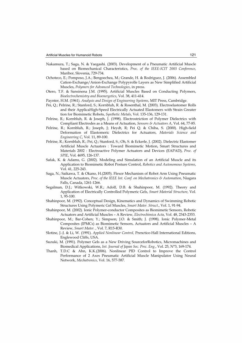
Artificial Muscles for Humanoid Robots 121
Nakamura, T.; Saga, N. & Yaegashi. (2003). Development of a Pneumatic Artificial Muscle based on Biomechanical Characteristics, Proc. of the IEEE-ICIT 2003 Conference,Maribor, Slovenia, 729-734.
Ochoteco, E.; Pomposo, J.A.; Bengoechea, M.; Grande, H. & Rodriguez, J. (2006). Assembled Cation-Exchange/Anion-Exchange Polypyrolle Layers as New Simplified Artificial Muscles, Polymers for Advanced Technologies, in press.
Otero, T.F. & Sansinena J.M. (1995). Artificial Muscles Based on Conducting Polymers, Bioelectrochemistry and Bioenergetics, Vol. 38, 411-414.
Paynter, H.M. (1961). Analysis and Design of Engineering Systems, MIT Press, Cambridge. Pei, Q.; Pelrine, R.; Stanford, S.; Kornbluh, R. & Rosenthal, M. (2003). Electroelastomer Rolls
and their ApplicaHigh-Speed Electrically Actuated Elastomers with Strain Greater tion for Biomimetic Robots, Synthetic Metals, Vol. 135-136, 129-131.
Pelrine, R.; Kornbluh, R. & Joseph, J. (1998). Electrostriction of Polymer Dielectrics with Compliant Electrodes as a Means of Actuation, Sensors & Actuators A, Vol. 64, 77-85.
Pelrine, R.; Kornbluh, R.; Joseph, J; Heydt, R; Pei Q. & Chiba, S. (2000). High-field Deformation of Elastomeric Dielectrics for Actuators, Materials Science and Engineering C, Vol. 11, 89-100.
Pelrine, R.; Kornbluh, R.; Pei, Q.; Stanford, S.; Oh, S. & Eckerle, J. (2002). Dielectric Elastomer Artificial Muscle Actuators : Toward Biomimetic Motion, Smart Structures and Materials 2002 : Electroactive Polymer Actuators and Devices (EAPAD), Proc. of SPIE, Vol. 4695, 126-137.
Safak, K. & Adams, G. (2002). Modeling and Simulation of an Artificial Muscle and its Application to Biomimetic Robot Posture Control, Robotics and Autonomous Systems,Vol. 41, 225-243.
Saga, N.; Saikawa, T. & Okano, H.(2005). Flexor Mechanism of Robot Arm Using Pneumatic Muscle Actuators, Proc. of the IEEE Int. Conf. on Mechatronics & Automation, Niagara Falls, Canada, 1261-1266.
Segalman, D.J.; Witkowski, W.R.; Adolf, D.B. & Shahinpoor, M. (1992). Theory and Application of Electrically Controlled Polymeric Gels, Smart Material Structure, Vol. 1, 95-100.
Shahinpoor, M. (1992). Conceptual Design, Kinematics and Dynamics of Swimming Robotic Structures Using Polymeric Gel Muscles, Smart Mater. Struct., Vol. 1, 91-94.
Shahinpoor, M. (2002). Ionic Polymer-conductor Composites as Biomimetic Sensors, Robotic Actuators and Artificial Muscles – A Review, Electrochimica Acta, Vol. 48, 2343-2353.
Shahinpoor, M.; Bar-Cohen; Y.; Simpson; J.O. & Smith; J. (1998). Ionic Polymer-Metal Composites (IPMCs) as Biomimetic Sensors, Actuators and Artificial Muscles – A Review, Smart Mater. , Vol. 7, R15-R30.
Slotine, J.-J. & Li, W. (1991). Applied Nonlinear Control, Prenctice-Hall International Editions, Englewood Cliffs, USA.
Suzuki, M. (1991). Polymer Gels as a New Driving SourceforRobotics, Micromachines and Biomedical Applications, Int. Journal of Japan Soc. Prec. Eng., Vol. 25, N°3, 169-174.
Thanh, T.D.C & Ahn, K.K.(2006). Nonlinear PID Control to Improve the Control Performance of 2 Axes Pneumatic Artificial Muscle Manipulator Using Neural Network, Mechatronics, Vol. 16, 577-587.
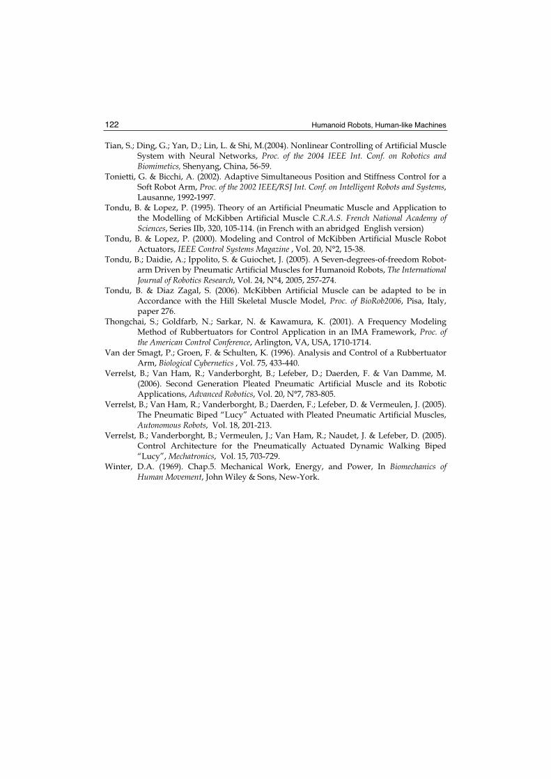
Humanoid Robots, Human-like Machines 122
Tian, S.; Ding, G.; Yan, D.; Lin, L. & Shi, M.(2004). Nonlinear Controlling of Artificial Muscle System with Neural Networks, Proc. of the 2004 IEEE Int. Conf. on Robotics and Biomimetics, Shenyang, China, 56-59.
Tonietti, G. & Bicchi, A. (2002). Adaptive Simultaneous Position and Stiffness Control for a Soft Robot Arm, Proc. of the 2002 IEEE/RSJ Int. Conf. on Intelligent Robots and Systems,Lausanne, 1992-1997.
Tondu, B. & Lopez, P. (1995). Theory of an Artificial Pneumatic Muscle and Application to the Modelling of McKibben Artificial Muscle C.R.A.S. French National Academy of Sciences, Series IIb, 320, 105-114. (in French with an abridged English version)
Tondu, B. & Lopez, P. (2000). Modeling and Control of McKibben Artificial Muscle Robot Actuators, IEEE Control Systems Magazine , Vol. 20, N°2, 15-38.
Tondu, B.; Daidie, A.; Ippolito, S. & Guiochet, J. (2005). A Seven-degrees-of-freedom Robot-arm Driven by Pneumatic Artificial Muscles for Humanoid Robots, The International Journal of Robotics Research, Vol. 24, N°4, 2005, 257-274.
Tondu, B. & Diaz Zagal, S. (2006). McKibben Artificial Muscle can be adapted to be in Accordance with the Hill Skeletal Muscle Model, Proc. of BioRob2006, Pisa, Italy, paper 276.
Thongchai, S.; Goldfarb, N.; Sarkar, N. & Kawamura, K. (2001). A Frequency Modeling Method of Rubbertuators for Control Application in an IMA Framework, Proc. of the American Control Conference, Arlington, VA, USA, 1710-1714.
Van der Smagt, P.; Groen, F. & Schulten, K. (1996). Analysis and Control of a Rubbertuator Arm, Biological Cybernetics , Vol. 75, 433-440.
Verrelst, B.; Van Ham, R.; Vanderborght, B.; Lefeber, D.; Daerden, F. & Van Damme, M. (2006). Second Generation Pleated Pneumatic Artificial Muscle and its Robotic Applications, Advanced Robotics, Vol. 20, N°7, 783-805.
Verrelst, B.; Van Ham, R.; Vanderborght, B.; Daerden, F.; Lefeber, D. & Vermeulen, J. (2005). The Pneumatic Biped “Lucy” Actuated with Pleated Pneumatic Artificial Muscles, Autonomous Robots, Vol. 18, 201-213.
Verrelst, B.; Vanderborght, B.; Vermeulen, J.; Van Ham, R.; Naudet, J. & Lefeber, D. (2005). Control Architecture for the Pneumatically Actuated Dynamic Walking Biped “Lucy”, Mechatronics, Vol. 15, 703-729.
Winter, D.A. (1969). Chap.5. Mechanical Work, Energy, and Power, In Biomechanics of Human Movement, John Wiley & Sons, New-York.
Humanoid Robots, Human-like MachinesEdited by Matthias Hackel
ISBN 978-3-902613-07-3Hard cover, 642 pagesPublisher I-Tech Education and PublishingPublished online 01, June, 2007Published in print edition June, 2007
InTech EuropeUniversity Campus STeP Ri Slavka Krautzeka 83/A 51000 Rijeka, Croatia Phone: +385 (51) 770 447 Fax: +385 (51) 686 166www.intechopen.com
InTech ChinaUnit 405, Office Block, Hotel Equatorial Shanghai No.65, Yan An Road (West), Shanghai, 200040, China
Phone: +86-21-62489820 Fax: +86-21-62489821
In this book the variety of humanoid robotic research can be obtained. This book is divided in four parts:Hardware Development: Components and Systems, Biped Motion: Walking, Running and Self-orientation,Sensing the Environment: Acquisition, Data Processing and Control and Mind Organisation: Learning andInteraction. The first part of the book deals with remarkable hardware developments, whereby completehumanoid robotic systems are as well described as partial solutions. In the second part diverse results aroundthe biped motion of humanoid robots are presented. The autonomous, efficient and adaptive two-leggedwalking is one of the main challenge in humanoid robotics. The two-legged walking will enable humanoidrobots to enter our environment without rearrangement. Developments in the field of visual sensors, dataacquisition, processing and control are to be observed in third part of the book. In the fourth part some "mindbuilding" and communication technologies are presented.
How to referenceIn order to correctly reference this scholarly work, feel free to copy and paste the following:
Bertrand Tondu (2007). Artificial Muscles for Humanoid Robots, Humanoid Robots, Human-like Machines,Matthias Hackel (Ed.), ISBN: 978-3-902613-07-3, InTech, Available from:http://www.intechopen.com/books/humanoid_robots_human_like_machines/artificial_muscles_for_humanoid_robots

© 2007 The Author(s). Licensee IntechOpen. This chapter is distributed under the terms of theCreative Commons Attribution-NonCommercial-ShareAlike-3.0 License, which permits use,distribution and reproduction for non-commercial purposes, provided the original is properly citedand derivative works building on this content are distributed under the same license.