
Artificial Intelligence in Manufacturing, Assembly and ...kogs- · Artificial Intelligence in...
44
Artificial Intelligence in Manufacturing, Assembly and Robotics edited by Prof. Dr. Horst 0. Bunke Universität Bern UN1VERSiTÄT - FrAchbcr-,; ; R. Oldenbourg Verlag München Wien 1988 dfdreetsw4
Transcript of Artificial Intelligence in Manufacturing, Assembly and ...kogs- · Artificial Intelligence in...
Artificial Intelligence in Manufacturing, Assembly and Robotics edited by
Prof. Dr. Horst 0. Bunke Universität Bern
UN1VERSiTÄT - FrAchbcr-,; ;
R. Oldenbourg Verlag München Wien 1988
dfdreetsw4

CIP-Titelaufnahme der Deutschen Bibliothek
Artificial intelligence in manufacturing, assembly and robotics / ed. by Horst 0. Bunke. — München ; Wien : Oldenbourg, 1988
ISBN 3-486-20920-5
NE: Bunke, Horst 0. [Hrsg.]
© 1988 R. Oldenbourg Verlag GmbH, München
Das Werk einschließlich aller Abbildungen ist urheberrechtlich geschützt. Jede Verwertung außerhalb der Grenzen des Urheberrechtsgesetzes ist ohne Zustimmung des Verlages unzu-lässig und strafbar. Das gilt insbesondere ftir Vervielfältigungen, Übersetzungen, Mikrover-filmungen und die Einspeicherung und Bearbeitung in elektronischen Systemen.
Umschlagentwurf: Mendell & Oberer, München Gesamtherstellung: Rieder, Schrobenhausen
ISBN 3-486.20920-5

Table of Contents
Preface VI
Acknowledgement VII
Surveys and Tutorials
K. Kempf Practical Applications of Artificial Intelligence in Manufacturing 1 B. Neumann Configuration Expert Systems: a Case Study and Tutorial 27 1.-P. Müller Planning for Artificial Intelligence Based Robots 69
Research Projects and Applications
'Autonomous Robots
K. Konolige Integrating Perception, Action, and Intention: the ICA Project 95 1-P. Müller MARS: Mobile Autonomous Robot Systems 103
Flexible Manufacturing
C. V. Rusca The IRMA Project: Towards a Robust Parallel Logic Programming Environment in Robotics 113 R. R. Bless / M. A. Müller Automated Robotic Assembly 129 E. Gmür I H. Bunke PHI-1: a Robot Vision System Based an CAD-Modells 145
Configuration Expert Systems P. Rixhon ■ Integrated Configuration Systems: the „Mehrstrom Experience" 165
Subject Index Reference Index Author's Addresses About the Editor
177 181 183 185

Configuration Expert Systems: a Case Study and Tutorial Bernd Neumann
Summary
This contribution discusses the architecture of expert
systems for configuration tasks in technical domains with the
objective to develop application-specific tools for expert
system development. In the first part of the paper four
configuration systems (XCON, SICONFEX, MMC-Kon and ALL-
RISE) are analyzed with regard to their architectural features and experiences gained during the development. From these
examples and similar evidence in several other systems one
can conclude that a knowledge-based architecture much different from the conventional rule-based architecture is
adequate for configuration systems. The main components of
the configuration system architecture are described in the
second part. The particular design presented in this paper is based an research in project TEX-K.
28
Bernd Neumann
1. Introduction
As expert systems are being developed for an increasing range
of applications, it becomes necessary to distinguish classes,
find commonalities and recognize domain-dependent features.
This is, of course, common practice in all fields where
progress depends an practical experience and experimentation.
As more and more examples can be studied, the conceptual structure of the field becomes apparent. lt seems, however,
that this development is particularly slow in the field of
expert systems. While the number of systems being developed
is skyrocketing and the number of systems being put to use is
also increasing, though much more modestly, application-
dependent architectural distinctions remain quite coarse.
This is not to say that application categories are not being
distinguished in this field. Hayes-Roth et al. [15] suggest the 10 categories interpretation, prediction, diagnosis, design,
planning, monitoring, debugging, repair, instruction, and
control which henceforth have been cited abundantly. But
there are few specific architectural characteristics which
can be associated with each of these categories. The best one
can do is to distinguish two main categories among the 10,
diagnosis type and configuration type applications. In
diagnosis applications backward chaining prevails, while most configuration applications employ forward chaining.
Also, one often needs uncertain reasoning for diagnosis but rarely for configuration. Apart of these major distinctions the
notion of an expert system frame work supposedly common
for all applications is generally put forth. If distinctions in
architecture are discussed, they are usually related to varying
degrees of problem complexity rather than types of applications. In [15] we find a decision tree relating
particular problem solving methods (and hence architectural
distinctions) to rather abstract domain characteristics. For
example, constraint propagation should be employed if subproblems interact, belief revision employed if search efficiency needs improving, etc.

Configuration Expert Systems 29
A similar picture is drawn in a recent 450 page tutorial an
expert systems [19]. Variations in system architecture are
described in terms of the relative importance of the five main
components of a system: inference engine, knowledge-base,
user-system interface, explanation facility, and knowledge
acquisition facility. Real-time process control systems, for
example, would have little need for a system-user interface;
if problem solving knowledge was still unfolding, one would
need a good knowledge acquisition facility, etc. This amounts
to saying that there is essentially one basic expert system
architecture for all applications.
A 'flat' view of expert system architectures is also taken by
most tool builders: Expert system development aids and Shells are generally designed to cover 'all' applications. As the
requirements vary noticeable, hybrid tools are provided which
offer a selection of alternative components and methods to
choose from. But there are few tools specially designed for
particular application categories, diagnosis tools being the
prominent exception (see e.g. the excellent analysis in [28]).
As it turned out, even diagnosis tasks may not be treated
alike. For certain domains 'second generation expert systems'
[29,37,38] are being proposed and developed. Their architecture may be quite different from conventional systems, employing, for example, deep models of the
respective domain to support causal reasoning. Hence the
boundary lines of diagnosis application categories are quite
likely to be redrawn according to the need for such
architectural features.
This contribution discusses the architectural requirements of another traditional application category, configuration expert
systems. We use the term 'configuration' here in a broad
sense:
A configuration system is an expert system which
helps to assemble components into an aggregate
according to some goal specification and using
expert knowledge.

30
Components may be physical objects or other entities (e.g. actions or methods). They may be chosen from an infinite
repertoire (e.g. including objects with a continuous range of
attribute values). The process of assembling components into
a configuration may involve decisions concerning type and
properties of individual components as well as relations
between several components. The goal specification may
contain any information regarding the final aggregate
including constraints, optimality criteria, functional
requirements, etc. There may be any number of acceptable
solutions, including none at all.
We also assume that the configuration system does not
employ a ciosed-form solution procedure but a step-by-step
strategy. Each step typically involves a decision or
assumption concerning the solution aggregate. Hence one may
think of a configuration system as an Al problem solver and
the configuration steps as decisions in a search graph.
Much of what is known about control techniques in Al problem solving also applies to the configuration task. Finding an
acceptable configuration may require judicious choices at
intermediate decision nodes, possibly based an heuristic
information. In general, control strategies ranging from
simple depth-first search to dependency-directed
backtracking may be called for.
lt should be clear by now that our definition of configuration
encompasses construction, design, planning and other rather
diverse activities. Here are some examples which are in
accord with our definition:
- selecting components for a power supply given performance
requirements - designing the floor plan of a house - planning a sequence of laboratory experiments
Bernd Neumann
Configuration Expert Systems
31
- configuring a computer system according to customer
wishes
- selecting and placing office furniture
- specifying work plans for a manufacturing process
- configuring a computer vision system for quality control
The paper is organized as follows. In Section 2, following this
introduction, we review the literature and discuss selected
systems in more detail. We focus an a major subcategory of configuration systems, loosely called 'technical' configuration
systems. Their distinguishing feature is highly structured
domain knowledge, or more precisely, a solution space which
is decisively governed by well-documented technical
information. Most configuration tasks tackled by expert
systems so far and all of the examples given above fall into
this category.
In Section 3 we describe the details of a knowledge-based
architecture adequate for configuration systems. The
architecture differs from the conventional expert system
architecture in several respects, particularly in its
deemphasis of rule-based knowledge representation. The search for a solution is prestructured to a large extent by a hierarchical representation of admissible configurations.
We also report about the configuration system tool PLAKON
which is being developed in a joint project in the FRG. Much of
the insights presented in this paper have resulted from
research for PLAKON. At this point I want to express my
gratitude and appreciation for contributions of R. Cunis, A.
Günter and I. Syska at the Universität Hamburg and of all other
project members.
32
Bernd Neumann
2. What Can We Learn from Experience: Four Examples
In this section we tap the considerable body of experience
concerning the design of configuration systems. Our goal is a
critical analysis of implemented systems with regard to their
architectural features. What can we learn from these
applications?
To this end we view each system as a problem solving system
whose behavior depends an three types of knowledge:
1. general domain knowledge
2. problem-specific domain knowledge
3. problem-solving knowledge
The first body of knowledge encompasses facts, properties
and relations of the application domain including the
underlying conceptual structures. Different from the second
type, domain knowledge is assumed to be valid for all
problems of an application domain, hence it is sometimes
called 'static'. For configuring power supplies, for example,
domain knowledge would include component descriptions,
relevant physical laws, cooling requirements, industrial
standards, etc. We do not want to distinguish from general,
domain-independent knowledge, e.g. laws for spatial and
temporal reasoning. Such knowledge is assumed to be part of the domain knowledge base.
The second type of knowledge is specific for a particular
problem. lt includes the problem specification and all other
information pertaining to a specific solution. As more and
more problem-specific knowledge is accumulated in course of
the problem solving process, this knowledge base is often
called 'dynamic'. Note that both (1) and (2) can be viewed as
knowledge constraining the solution space. Both account for
admissible solutions but not for procedures to find them. This
is left for the third knowledge type.
Configuration Expert Systems 33
Problem-solving knowledge is defined here as knowledge
pertaining to the order in which configuration decisions
should be made. lt provides control for the problem solving
process in terms of strategies, methods, subtask
organizations, sequencing information, etc. We shall see that
problem-solving knowledge - although conceptually separable - is mixed up with domain knowledge in most applications.
This is Iargely due to the use of situation-action rules which
encourage unstructured knowledge representation. We want to
elaborate this point a little further.
Control in a rule-based system tends to be diffuse by the very
nature of rule-based systems: Rules are essentially a way of
defining a process without defining control. Hence rule-based systems are best suited for applications where a global flow
of control need not be specified. If one has to enforce a
certain order of problem-solving steps in a rule-based
system, one must provide control knowledge in terms of
appropriate firing conditions on the left-hand sides of the
rules. This is often accomplished by introducing 'contexts'
which are turned on and off to enable rules in the proper
sequence. A second form of control, of course, is given by the
conflict resolution strategy which provides arbitration when
more than one rule is ready to fire.
The three knowledge types have been introduced to permit a
structured inquiry into the use of knowledge in the application examples which will be discussed. We shall
examine how the respective bodies of knowledge are
represented and put to use for the respective problem solving
tasks.
2.1 R1/XCON
As a first example of a configuration system we take a look
at R1/XCON, the expert system for configuring DEC computers
34 Bernd Neumann
[1,20,32,43]. Given a customer's purchase order, XCON
determines substitutions and additions to make the order
consistent and produces a number of diagrams showing the spatial and logical relationships among the components. The
decisions to be made concern component types and properties,
placement of components into boxes and cabinets, electrical
connections among components, etc. XCON is a very large rule-
based system. lt currently contains more than 6200 rules
which draw on a database of approximately 20,000 parts. Furthermore, each year about half of the rules are expected to
change. Hence XCON also presents a formidable software maintenance task.
Static domain knowledge in XCON can be roughly subdivided
into component descriptions and knowledge about valid
(partial) configurations. Component descriptions are read in
from a component database. After reading them in they are
represented as simple OPS5 frame structures. We use the knowledge representation features such as defaults,
inheritance, facets, or procedural attachment. Knowledge
about valid (partial) configurations, e.g. compatibility of
components or placement requirements, is expressed in terms
of OPS5 rules, so-called productions. A production consists of
an arbitrary number of condition elements on the left-hand
side, in XCON on the average about 6, and an arbitrary number
of actions, e.g. modifications of the current working data, on the right-hand side.
ASSIGN-POWER-SUPPLY-1
I F : THE MOST CURRENT ACTIVE CONTEXT IS ASSIGNING A POWER SUPPLY AND AN SBI MODULE OF ANY TYPE HAS BEEN PUT INA CABINET AND THE POSITION IT OCCUPI ES IN THE CABINET IS KNOWN AND THERE IS SPACE IN THE CABINET FOR A POWER SUPPLY AND THERE IS NO AVAILABLE POWER SUPPLY AND THE VOLTAGE AND FREQUENCY OF THE COMPONENTS IS KNOWN
THEN: FIND A POWER SUPPLY OF THAT VOLTAGE AND FREQUENCY AND ADD IT TO THE ORDER
Figure 1: Sample rule of XCON (paraphrased)
Configuration Expert Systems
35
The example in Figure 1 illustrates how static domain
knowledge about valid configurations is coded in terms of
actions to be taken in a certain problem solving context. This
technique, although common practice in configuration
systems, leads to considerable unclarity as will be argued further down.
The problem description of XCON - which is part of the second
body of knowledge to be examined - is a list of components.
XCON detects missing or wrong components and corrects the
list while performing the configuration task. Note that a
problem specification in terms of a component list is much
less problematic than an indirect specification, e.g. in terms
of functional requirements or constraints. The latter would
necessitate component selection as part of the configuration task. For DEC computers this is done by the separate expert
system XSEL - discussed in [19] - which accepts customer
wishes as input and delivers a component list as output.
We now turn to problem-solving knowledge as represented and
used in XCON. lt is explicitly expressed by rules and implicitly by the conflict resolution strategies of OPS5. The control thus
achieved is remarkable. The configuration task is organized
into contexts which in effect specify a hierarchical system of
tasks, subtasks, sub-subtasks, etc. Figure 2 shows a sequence
of contexts taken from a trace in [20]. The number preceding
each context is the cycle an which that context was entered.
Each leaf of the subtask hierarchy typically consists of about
10 configuration steps corresponding to as many cycles of the
inference component. At the end of a subtask an appropriate
rule fires to establish a new subtask. Thus the order of
configuration steps is well-defined and - as it turned out -
hardly ever leads to backtracking.

36 Bernd Neumann
215 MAJOR-SUBTASK-TRANSITION 216 DELETE-UNNEEDED-ELEMENTS-FROM-WORKING-MEMORY
235 FILL-CPU-OR-CPU-EXTENSION-CABINET 240 ADD-UBAS 246 ASSIGN-POWER-SUPPLY 251 ADD-MBAS 252 DISTRIBUTE-MB-DEVICES 260 ASSIGN-SLAVES-TO-MASTERS 269 ASSIGN-POWER-SUPPLY 272 FILL-MEMORY-SLOTS 278 SHIFT-BOARDS 298 ADD-MEMORY-MODULE-SIMULATORS 305 ASSIGN-POWER-SUPPLY 312 FILL-CPU-SLOTS 318 ASSIGN-POWER-SUPPLY 322 ADD-NECESSARY-SIMULATORS 326 DELETE-TEMPLATES 340 DELETE-UNNEEDED-ELEMENTS-FROM-WORKING-MEMORY 353 FILL-CPU-OR-CPU-EXTENSION-CABINET 356 ADD-MBAS 359 ASSIGN-POWER-SUPPLY 362 ADD-UBAS 364 FILL-MEMORY-SLOTS 369 SHIFT-BOARDS 389 ADD-MEMORY-MODULE-SIMULATORS 396 ASSIGN-POWER-SUPPLY 399 TERMINATE-SBI 402 ADD-NECESSARY-SIMULATORS 406 DELETE-TEMPLATES 415 MAJOR-SUBTASK-TRANSITION
Figure 2: Sequence of contexts in XCON trace
As pointed out earlier, rule-based programming is best
matched to problems with a predominantly local control
structure. XCON is an atypical example as it uses rules to
establish a global flow of control. We want to learn from this
example, hence let us consider advantages and disadvantages
of the XCON architecture. Some interesting points are made in
a recent analysis [32] concerning the intelligibility of XCON's
written code. When modifying the rule set XCON's rule developers find it increasingly difficult to insure rule firing
in the proper order. As one of the reasons they name the inhomogeneity of the code: Diverse tricks have been used over
the years to force rules into a particular firing order. Also having a rule for more than one situation turned out to
Configuration Expert Systems
37
decrease intelligibility. When changing a rule one could not be
sure about its original purpose.
As a partial remedy a new high-level language RIME has been
developed for recoding XCON. RIME provides several means of
expressing structure in a rule-set. First, rules of common
purpose can be assigned to a 'problem space' corresponding to
a subtask. Hence the XCON subtask structure can be better
supported. Second, problern solving methods can be defined
and assigned to a problem space. For example, many subtasks
can be solved by performing four conceptual steps (the
following is a highly simplified description):
1. PROPOSE: Suggest operators for current goal. 2. ELIMINATE: Evaluate appropriateness of operators prune. 3. APPLY: Activate and execute operators.
4. EVALUATE: Review goal, redo or exit problem space.
By assigning this method to a problem space, RIME provides
rules which reinforce the corresponding sequence of steps.
Third, rule templates are provided which establish
permissible categories of rules and prohibit inhomogeneous
coding.
In summary, we find that a system like XCON requires means
for defining control, both in terms of a context structure and
methods for subtasks. A rule language such as OPS5, however,
is not well suited for defining control. The disadvantages may
not be decisive in small systems, but they become significant
in systems as large as XCON. Certainly, good software
engineering also applies to the design of expert system: A
mismatch between problem structure and programming language decreases software intelligibility and should be
avoided.

38 Bernd Neumann
2.2 SICONFEX
After having discussed XCON it is interesting to take a look at
the configuration system SICONFEX which provides a very
different solution for a similar task. SICONFEX has been
developed by Lehmann et al. at Siemens, Munich, in 1985
[14,17]. lt is an expert system for configuring the operating
system of SICOMP process control computers distributed by
Siemens. The input data consist of the hardware configuration
and application-specific customer requirements, e.g. with
respect to the intended use of system and user software. Requirements may be graded according to various degrees of
desirability. All input data are obtained in a user-friendly
dialogue supported by graphical displays. The system expects
only a naive understanding of hardware and software
components. After the input phase the system performs the
partitioning of the main storage. This is the core of the
configuration task. The system generates output in terms of
configuration statements for a generator program.
There are four distinct main storage regions to be configured,
three for the operating system and one for user programs.
Human experts were able to supply some 200 rules concerning
the configuration of the first three regions. However, many
heuristics and guide-lines had to be added by the developers
of SICONFEX. The system encompasses 6 MByte of code (including 4 MByte of INTERLISP-D/LOOPS code) which is
equivalent to a rule-based system of several thousand rules.
SICONFEX is not a rule-based system, however, as it employs
diverse methods of the LOOPS environment.
Let us examine the representation and use of the three
different types of knowledge again which we have introduced
earlier. Structuring static domain knowledge played a significant part in the development of SICONFEX. As the
authors report in [14], they found this task much underrated in
popular expert system literature. The SICONFEX domain
Configuration Expert Systems 39
consists of at least three distinct areas with quite diverse
characteristics:
1. the world of physical objects which are the configuration components
2. the abstract world of existing software modules 3. the artificial world of hypothetical memory partitionings
A variety of techniques have been used to represent such a
heterogeneous domain: frame-like object structures,
conceptual taxonomies, inheritance mechanisms, rules,
message passing, active values and LISP functions. The
authors stress that rules play only a subordinate rote. They are used with logical interpretation:
IF <premisses> THEN <conclusion>
Production rules as in OPS5, an the other hand, have
procedural semantics:
IF <pattern> THEN DO <actions>
Such rules are deemed unfit for representing static domain knowledge in SICONFEX - much in accord with our earlier remarks concerning XCON.
Problem-specific knowledge enters the system via the elaborate user-interface mentioned above. The need for
considerable programming efforts in this department has also
been reported by other authors [2,9], and it is worthwhile to
understand when and why this is so. Problem data are often
obtained from a user belonging to a category much different
from the knowledge engineers who structured the domain
knowledge. In the case of naive users (as with SICONFEX)
instant knowledge engineering has to be performed to
transiate user input into internal structures. The more
elaborate the system's knowledge representation and the more
40 Bernd Neumann
naive the user's, the wider is the gap which has to be bridged
by the user interface. Note that problem-specific domain knowledge is structurally not much different from static
domain knowledge. Hence components for acquiring domain
knowledge during system development may be put to use for user interfacing and vice versa.
There appears to be no extensive representation of problem solving knowledge in SICONFEX (in the sense defined earlier).
As the authors state in [17], experts could not provide
consistent strategies for partitioning the main storage. The
solution adopted in SICONFEX has algorithmic character. lt
involves discrete optimisation but also incorporates
heuristics and hypothetical decisions lieble for backtracking. Control is not expressed in terms of rules.
In summary, SICONFEX is a configuration system with an
architecture radically different from XCON. Its prominent
features are (1) a highly structured knowledge-base, (2) an elaborate user interface for acquiring problem data, and (3)
hybrid problem-solving techniques including optimisation algorithms.
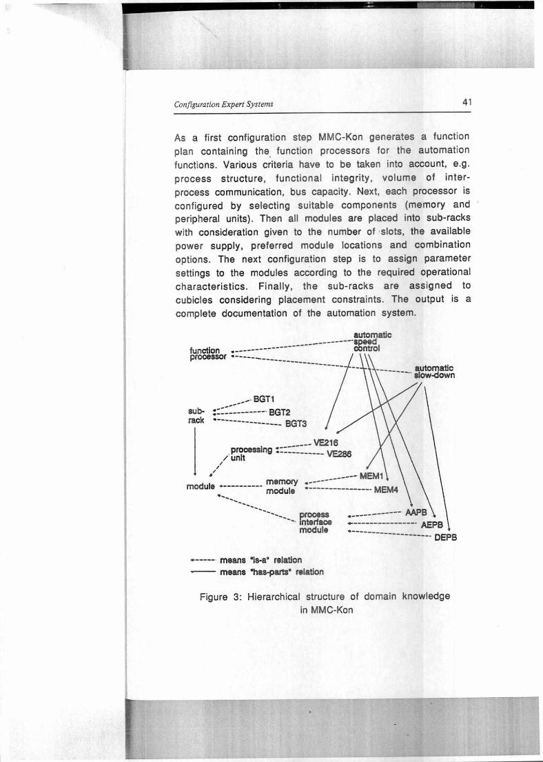
2.3 MMC-Kon
Our next example is the system MMC-Kon which configures distributed automation systems based an the SICOMP MMC 216
multi-microcomputer system. MMC-Kon has been developed by
Baginsky et al. at Siemens, Erlangen, as a first prototype for
testing general principles of configuration system design [2].
The particular domain of interest is rolling mill automation. A
typical task is defined in terms of several automation
functions to be performed by the system, e.g. thickness control, position control, automatic slow-down. The user
specifies a task interactively making use of reference
systems and MMC-Kon's knowledge base which contains all standard automation functions.
automatic ------- -speed
function . ------------------- control processor • ----- ----
----- automatic slow-down
BGT1 sub- ------- BGT2 reck • ---------------- BGT3
--------------
-- --- VE216 processing --- unit VE286
memory ._______---- MEM1
module MEMO
process . ----- _ ------ AAPB Interface AEPI3 module
------------------- • DEPB
ie./
module -
Configuration Expert Systems 41
As a first configuration step MMC-Kon generates a function plan containing the function processors for the automation functions. Various criteria have to be taken into account, e.g. process structure, functional integrity, volume of inter-process communication, bus capacity. Next, each processor is configured by selecting suitable components (memory and peripheral units). Then all modules are placed into sub-racks with consideration given to the number of siots, the available power supply, preferred module locations and combination options. The next configuration step is to assign parameter settings to the modules according to the required operational characteristics. Finally, the sub-racks are assigned to cubicles considering placement constraints. The output is a complete documentation of the automation system.
means 1s-a' relation means "has-Parts" relation
Figure 3: Hierarchical structure of domain knowledge in MMC-Kon

42
Bernd Neumann
The inherent characteristics of this application do not seem
much different from the preceding examples, yet there are
some novel features. As we examine the relevant domain
knowledge we find - as would be expected - conceptual descriptions of all objects which can make up a configuration.
In addition, however, the object frames are related to each
other by is-a and has-parts relations. The resulting hierarchical structure is shown in Figure 3 (taken from [2]).
Note that the individual modules (e.g. processing unit VE216
or memory unit MEM1) are represented from two perspectives:
as physical objects and as carriers of a function. The ability
to view objects from different perspectives, exposing certain
attributes and hiding others, is a valuable asset for
knowledge structuring and appears to play an important rote
in configuration system design.
Similar to SICONFEX the task definition is acquired
interactively. The system supports this phase using its
domain knowledge and the display capabilities of a modern workstation. There is also the option of referring to library
configurations. In this case the current task is defined by
modifying the selected reference task.
Control does not seem to play a critical rote in MMC-Kon.
There is a natural order in following through the configuration
steps, but the system has been designed to permit free user
interaction and changes of the order of configuration steps at
virtually any time. MMC-Kon ensures that the resulting
configurations are consistent, whichever decisions the user has made interactively. This desirable characteristic is in
distinct contrast to XCON where the order of configuration
steps is fixed and precludes user interaction. One may
attribute this to differences of the respective application
domains, but I am prepared to argue that MMC-Kon's pleasant
properties are mainly the result of better knowledge representation.
Configuration Expert Systems
43
We now turn to a different field of application: design in
engineering. Design has been characterized in [22] as a
problem solving activity aimed at constructing artifacts and meeting certain conditions. The artifact must
1. satisfy a given functional specification, 2. conform to limitations of resources, and
3. satisfy implicit and explicit criteria on its form.
From this definition design has enough in common with the
configuration examples encountered so far to be included in
our discussion. The main difference seems to be the emphasis
of form design rather than composition of components.
2.4 ALL-RISE
There is a rich set of literature on design aided by knowledge-
based systems. For an excellent analysis see [42], for
references see [8]. lt is not immediately clear which systems
fall into the category of configuration expert systems and
which do not. Most of the expert knowledge in engineering is
formalized and well documented to begin with, hence
automatising design is not really a matter of replacing or
simulating human experts. Consequently, much of the relevant
literature is oriented towards design automation and not
towards expert system development. But judged by
performance, knowledge representation techniques, and design
methods, several of these innocent-looking engineering tools
deserve the attention of expert system developers for configuration and - following [26] - possibly also diagnosis
tasks.
We focus now on the design system ALL-RISE [33,34] which
supports the preliminary structural design of buildings. The
input to ALL-RISE is an architectural or spatial plan of a
building represented by a three-dimensional grid (see Figure
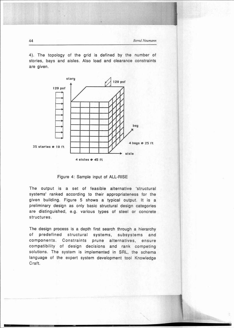
44 Bernd Neumann
4). The topology of the grid is defined by the number of
stories, bays and aisles. Also load and clearance constraints
are given.
120 psf
35 stories @ 10 ft
4 aisles @ 45 ft
Figure 4: Sample input of ALL-RISE
The output is a set of feasible alternative 'structural
systems' ranked according to their appropriateness for the given building. Figure 5 shows a typical output. lt is a
preliminary design as only basic structural design categories are distinguished, e.g. various types of steel or concrete structures.
The design process is a depth first search through a hierarchy
of predefined structural systems, subsystems and
components. Constraints prune alternatives, ensure
compatibility of design decisions and rank competing solutions. The system is implemented in SRL, the schema
language of the expert system development tool Knowledge Craft.

Configurafion Expert Systems
45
Alternative 1;
3D-material: steel 3D System: orthogonal 2D Subsystems:
Lateral-load: Outer (bay & aisle): rigid-frame (beam-column) Inner (bay & aisle): rigid-frame (beam-column)
Gravity-load: Floor-type: Reinforced slab Floor-support in aisle direction: 2 bay: column-plate aisle: simple-frame
NOTE: Lateral-load primarily resisted by rigid-frames
Figure 5: Partial output of ALL-RISE
ALL-RISE is interesting for our discussion of expert system
architectures because of two significant features. One is the
organization of static domain knowledge, the other is the
extensive use of constraints. We shall discuss these features in order.
The static knowledge hierarchy of ALL-RISE is similar to
other knowledge bases with respect to its use of schemas
(frames) and the predominance of is-a and has-parts
relationships for describing and relating the entities of the
domain. lt is special, however, because of the interpretation
assigned to the top node of the hierarchy. The top represents an acceptable structural system (a successful design) at its
most abstract level. Hence all solutions must be instances of this node or its specializations. Subordinate nodes represent
either alternative specializations (e.g. steel or concrete) or
partial designs (e.g. lateral-load design and gravity-load
design). Leaves of the hierarchy represent design choices
which need not be further refined. A complete design is a
subtree with the top node as the root, exactly one successor
for is-a branchings and all successors for has-part branchings. Note that this corresponds to a solution in a
conceptual AND-OR tree. Is-a branchings represent logical OR
relationships, has-part branchings represent logical AND

46 Bernd Neumann
relationships. Representing domain knowledge in this fashion
has the interesting property that decisions required for a
feasible design are explicitly represented. Furthermore,
conceptually related decisions are grouped together. Hence
making decisions in depth-first order beginning at the top
node is natural and conceptually justified. One can also argue that this order tends to minimize backtracking. The
advantages of a control flow following the AND-OR structure
of a problem domain are well-known in Al problem solving
[25]. Similar schemes have also been used in several other design and configuration systems [7,41].
The is-a and has-part hierarchy of ALL-RISE does not contain
complete domain knowledge as a large part is encoded by constraints attached to the knowledge hierarchy. The authors
distinguish (1) synthesis constraints which affect the
generation of feasible solutions, (2) interaction constraints
which arise from the interaction of structural subsystems,
(3) causal constraints which represent equations of
equilibrium and other physical laws, (4) parametric
constraints which constrain component attributes, and (5)
evaluation constraints which are used to rank alternative
structural designs. The following is a synthesis constraint represented by a SRL schema:
{{braced-frame-constraint CHILD-NODES: "mat-steel" "stories-less-than-40" CONNECTION-TYPE: and STATUS:
}}
The constraint can be paraphrased as the rule:
1F the current alternative is a braced frame, AND the material used is steel, AND the number of stories is less than 40
THEN eliminate the current alternative.
As a matter of fact, a rule representation has been used in HI-RISE, a precursor of ALL-RISE.
Configuration Expert Systems 47
Constraints are instantiated, propagated and satisfied when
encountered in the knowledge hierarchy. Interesting control
issues arise as design decisions of one partial design may be
affected by constraints triggered by another partial design.
Constraints are related to each other through common
attributes and form a network. Different from other work an
constraint-based reasoning [11,12,13,36] the developers of
ALL-RISE did not implement an independent constraint
propagation machinery capable of satisfying multiple
constraints simultaneously. They preferred a step-by-step
procedure oriented at the domain knowledge hierarchy.
2.5 Planning
Another application area related to our topic is planning, at
first glance quite different from configuration and design. The
basic similarities become apparent, however, if one views a
plan as a configuration of operations or actions. Plan
formation means selecting operations from a repertoire to
meet certain boundary conditions and constraints, e.g. a
desired final state.
There is a vast body of literature concerning planning systems as planning has been an Al research area long before the
advent of expert systems [10,30,31,39]. Today, several
different models are considered interesting, for a survey see
[18,35]. The most popular originated from the work of
Sacerdoti [30,31]. Each step in a plan is modeled as an
operator along with preconditions and a description of the
state change caused by that operator. Sacerdoti also
emphasized the need for hierarchical planning in tvvo respects. First, he organized the repertoire of operators into a hierarchy to allow planning at different levels of abstraction
(e.g. 'travel' vs. 'travel-by-train'). Second, he differentiated
the preconditions along a coarse-to-fine scale.
48
In modern application-oriented planning systems several
other features are also important [18], for example flexible
user interaction, display facilities, alternative plans, special
planning strategies, optimization methods, etc. The basic
structure of a planning system, however, including the
preference of a hierarchical approach, conforms well with the
basic structure of a configuration system. A more detailed
proposal for impiementing a planning system with
configuration system components has been worked out in [4].
3. The Kernet of a Technical Configuration System
The discussion of selected configuration systems in the preceding section has revealed differences and
commonalities, convincing solutions and less convincing ones.
This should provide some background for the following
sections where we propose components and architectural
features for future configuration systems. The proposal is
largely based on research carried out in project TEX-K which
will be described later. But many ideas have also been put
forth in the literature in connection with application-oriented
work as evident from the examples in the preceding section.
We are guided by the following main insights concerning configuration system architecture:
1. For a large class of configuration tasks, especially in technical domains, the configuration process is governed by highly structured knowledge about components and aggregates. Expert rules play a subordinate rote.
2. Domain knowledge is naturally organized into two bodies: an object-oriented knowledge hierarchy based on is-a and
has-parts relationships, and a constraint network relating object properties to each other.
Bernd Neumann
Configuration Expert Systems
49
3. The order of configuration steps may vary considerably
depending on the particular problem, the availability of
library solutions, the amount of user interaction and the strategy chosen.
4. An elaborate user interface is a major subtask of
configuration system development. Its main purpose is
interacting with the knowledge base.
The kernet which will be described in the following
constitutes an architectural framework in accord with the above views.
3.1 Conceptual Knowledge
Conceptual knowledge is a structured description of
permissible configurations. As stated above we distinguish
between a hierarchical object-oriented representation and constraints. In the following we focus on the hierarchical
representation and begin with the conceptual hierarchy.
3.1.1 Conceptual hierarchy
The conceptual hierarchy is a lattice of conceptual object
descriptions based on the is-a relationship. Its purpose is to
characterize the objects with which one has to deal in the
application domain. A flat collection of frames is clearly not
sufficient as different levels of abstraction play an important
rote in step-by-step configuration. The is-a relationship
supports well-known techniques of property inheritance [3].
The top-most part of the conceptual hierarchy is domain-
independent and predefined. Figure 6 (adapted from [6]) shows
a typical root section of the conceptual hierarchy.
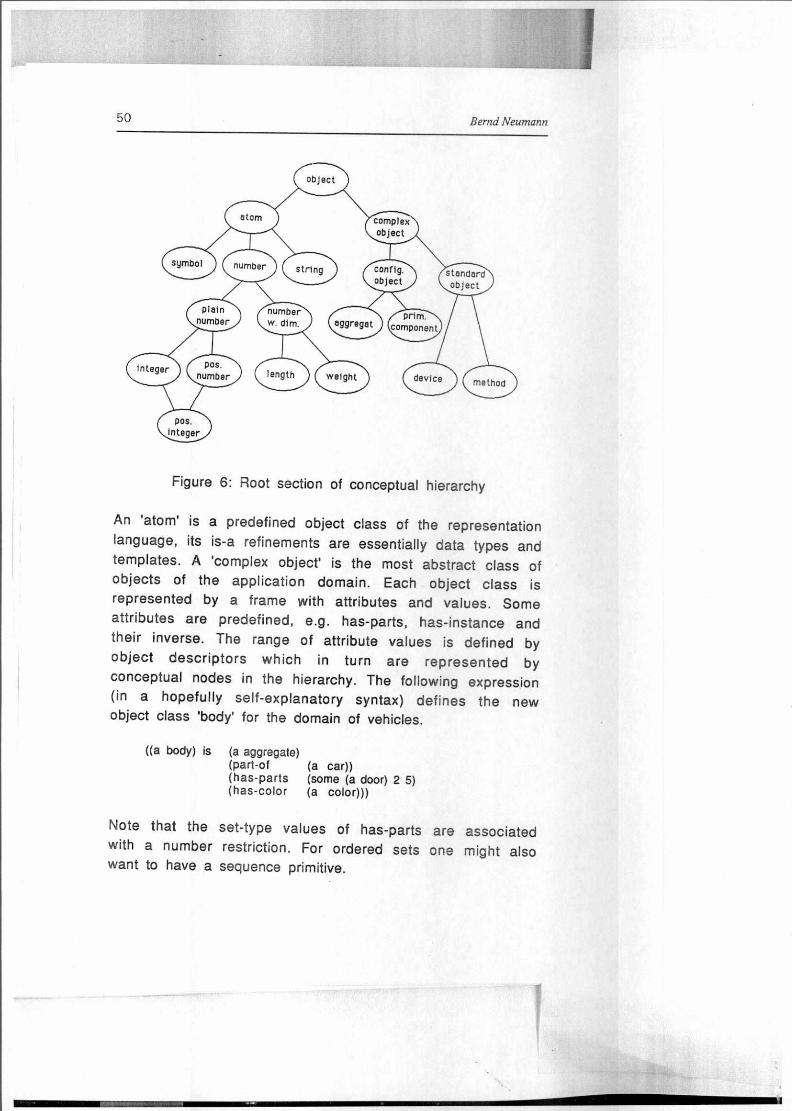
complex object
50 Bernd Neumann
Figure 6: Root section of conceptual hierarchy
An 'atom' is a predefined object dass of the representation
language, its is-a refinements are essentially data types and
templates. A 'complex object' is the most abstract dass of objects of the application domain. Each object dass is
represented by a frame with attributes and values. Some attributes are predefined, e.g. has-parts, has-instance and
their inverse. The range of attribute values is defined by
object descriptors which in turn are represented by
conceptual nodes in the hierarchy. The following expression
(in a hopefully self-explanatory syntax) defines the new object dass 'body' for the domain of vehicies.
((a body) is (a aggregate) (part-of (a car)) (has-parts (some (a door) 2 5) (has-color (a color)))
Note that the set-type values of has-parts are associated with a number restriction. For ordered sets one might also want to have a sequence primitive.

ü.e.V.te
51 Configuration Expert Systems
All these techniques are well-known in Al knowledge representation but unfortunately not always supported in expert system tools. We shall not elaborate these techniques but rather briefly discuss an additional, less well-developed representation feature which is useful for configuration systems: aspects of an object.
The need for aspects has been pointed out in the discussion of MMC-Kon where a configuration was viewed as a system of automation functions in the first phase and as a hardware system in the second. The configuration as a whole encompasses both, attributes and components of the functional aspect and attributes and components of the hardware aspect. To represent aspects in the conceptual knowledge hierarchy we allow attributes to be bundled and bundles to be given aspect names. For example, we define the software and hardware aspects of a computer system as seen below. With 'computer-system/SW' one can address the software aspect of the concept 'computer-system' just like a complete node. Also, is-a and has-parts successors can be defined within any of the aspects. See [6] for a more detailed presentation of the aspect feature.
(a computer-system) is (a aggregate) (:SW (a software-system)
(has-parts (Set (a operating-system) (a user-program))))
(:HW (a device) (has-parts (set (a processor)
(a memory)))))
The has-parts attribute, of course, is a key attribute for representing aggregates. As the main idea is to represent permissible configurations, the has-parts attribute is used to build a compositional hierarchy with 'permissible-configuration' as the top node. All possible alternatives for partial configurations and components can be reached from
the top node via is-a and has-parts refinements. The graph below 'permissible-configuration' can be interpreted as an
52 Bernd Neumann
AND-OR graph as pointed out earlier. The solution of the configuration problem is a solution tree in this AND-OR graph. The complete hierarchical knowledge base encompasses additional nodes, however, as should be clear from Figure 6.
3.1.2 Constraints
Constraints are a common way to express conditions on, or mutual dependencies between, objects and properties. For discrete property values, a constraint can be viewed as a relation in the mathematical sense. lt defines a restricted subset of combinations of property values among the set of all possible combinations, e.g. the subset of exhaust systems compatible with car engine types and export destinations. Constraints can be viewed as a general way of expressing N-ary relationships, complementing the binary attribute relationships in frames.
For several reasons constraints require special treatment. First, they do not conform with the object-oriented style of knowledge representation discussed so far. A typical constraint involves more than one object and cannot be assigned to any single object by a good reason. Second, constraints tend to affect the order of configuration steps in a way much different from the path lined out by the hierarchical knowledge base. This is known from human problem-solving where narrowly constrained choices are typically considered first. There is also a growing body of research concerning constraint-based problem-solving and effective procedures for evaluating constraint knowledge [4,13,21,36,40]. Third, humans frequently use constraints in their own thinking and language when they want to characterize a solution space. Hence it certainly facilitates knowledge engineering if constraints can also be formally expressed in a computer system. In summary, there is much evidence that a tool box for configuration system development should provide means for representing and exploiting

Configuration Expert Systems
53
constraints. In the following we outline an approach originally
proposed by Güsgen [13] and further developed in project TEX-K [24].
Constraints are defined using constraint classes. A constraint
class is comparable to a procedure declaration with formal
parameters and a body specifying the restrictions or
functional dependencies between the parameters. Constraints
are tied to domain knowledge via so-called conceptual
constraints. A conceptual constraint consists of two parts,
one specifying the bindings of constraint variables to objects
of the knowledge base, the other specifying the bindings of
the parameters of a constraint class to attributes of the selected objects. The following expression describes a
conceptual constraint which may be used to force the 'has-
weight' attribute of a car to take an the sum of the component weights.
(constrain ( (?C (a car))
( ?B (a body (part-of ?C)))
(?F (a frame (part-of ?C))))
(add (?B has-weight) (?F has-weight) (?C has-weight)))
lt is assumed that a constraint class 'add' with three
parameters has been defined. Note that the formal Syntax is just a way of entering constraints into the knowledge base.
The internal representation is a frame-like data structure
with links into the appropriate attribute slots of object frames.
This short sketch of constraint classes and conceptual constraints, of course, is not all there is to be said about
constraints. The theme will be taken up again in the following sections.
3.2 Problem-Specific Domain Knowledge
In a configuration problem we deal with concrete instances of
components, aggregates and constraints. Für example, we may

54 Bernd Neumann
have to construct a configuration from a component list as in
XCON or from certain grid measures and load constraints as in
ALL-RISE. Given a conceptual knowledge base as discussed
above, such items are represented as instances linked
bidirectionally to the proper concept nodes via 'has-instance'
and 'instance-of' links. Instances inherit all attributes and
predefined values. To maintain strict inheritance, instance
properties may not 'overwrite' inherited properties. All this
corresponds to common practice in Al knowledge
representation and will not be elaborated further.
We focus now an the dynamic aspects of problem-specific
knowledge. In course of the configuration process many,
possibly tentative, decisions are male and partial, possibly
alternative, configurations are constructed. These partial
configurations will be called elaborations henceforth. In order
to realize various control strategies, including sophisticated
techniques like dependency directed backtracking, we must be able to represent the history of elaborations. lt has the
structure of a lattice with each node representing an elaboration and links connecting successive elaborations. Each
link also contains information about the configuration step represented by that link. The problem with such a structure
is its size in terms of required storage. In order to avoid
multiple representations each instance should be represented
only once. The elaboration history can thus be reduced to a
history of changing attribute values. In some programming
environments (e.g. Knowledge Craft) a context mechanism is provided which can be used for this purpose. Generally,
however, expert system tools do not supply effective
representation techniques for the elaboration history.
Another representation requirement is related to the dynamic
use of constraints. Constraint propagation is a dynamic
process which generates restrictions an attribute values. The
workings of constraint propagation will be discussed further
down, at this point it is important to note that attribute value

configuration Expert Systems
55
restrictions, changing over time, have to be represented as
part of the problem-specific knowledge. Furthermore, one may
want to distinguish between value restrictions arising from
different constraint sets, for instance 'soft' constraints and
'hard' constraints. All this requires an organization of
attributes into multiple facets, each facet corresponding to a distinct value modality.
3.3 Problem-Solving Knowledge and Control
We have designed the domain knowledge base in such a way
that information about permissible configurations is made
explicit. Hence inferences concerning the properties of a configuration can be based upon this knowledge and need not
resort to rules. What remains to be defined is the order of such inferences and the mechanism which carries them out.
As we have departed from a rule-based approach we can
devise a control scheme which is Iargely independent of
domain knowledge and allows the explicit representation of control knowledge.
3.3.1 Elementary configuration steps
At any given time an elaboration consists of a set of object
instances linked to conceptual nodes at various levels of the
knowledge hierarchy. The following elementary configuration
steps can be carried out depending an the state of the elaboration:
1. decomposition of an object along has-parts 2. specialization of an object along is-a-inverse 3. aggregation of components along part-of
(= has-parts-inverse) 4. merging of objects which can be replaced by a single one 5. value assignment or restriction 6. instantiation of a new object
56 Bernd Neumann
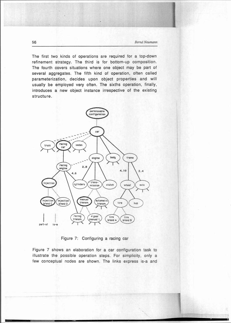
The first two kinds of operations are required for a top-down
refinement strategy. The third is for bottom-up composition.
The fourth covers situations where one object may be part of
several aggregates. The fifth kind of operation, often called
parameterization, decides upon object properties and will
usually be employed very often. The sixths operation, finally,
introduces a new object instance irrespective of the existing
structure.
• seden
engine
trans- mission
racing engine
2..8
4..6
cyl inder
CI) 4._ 10
clutch ( whe e I
2..4 • inlection brand C
injectIon brand D
menuel trensm
autametic trensm.
racing trensm.
4 gear menue, t.
tire brand A
tire brand B
port-of IS-6
Figure 7: Configuring a racing car
Figure 7 shows an elaboration for a car configuration task to
illustrate the possible operation steps. For simplicity, only a
few conceptual nodes are shown. The links express is-a and
Configuration Expert Systems 57
part-of relationships. The numbers associated with some of
the part-of links indicate restrictions on the number of parts.
Nodes which are assumed to be instantiated are drawn in heavy lines. Up to this stage it has been decided to configure a
racing car with manual transmission and a particular brand of fuel injection. The following elementary configuration steps can be carried out next:
- decompose 'racing car'
- specialize 'manual transmission'
- assign values to any of the instantiated objects - instantiate a new object
This example also demonstrates the advantages of top-down strategies regarding conflict avoidance. If 'manual
transmission' is specialized to '4 gear manual transmission'
instead of 'racing transmission', this would be in conflict
with the choice of a 'racing car'. A strict top-down strategy
does not produce incompatible decisions of this kind.
3.3.2 Representing control knowledge
The preceding section has shown that in general, one of several configuration steps can be carried out at any time. We
now discuss ways to make use of this degree of freedom. The
main idea is to define explicit control strategies which
provide selection criteria and other useful control
information. In more detail, a strategy contains the following:
1. Operation focus: This criterion focuses on a subset of the six elementary configuration operations.
2. Partial configuration focus: This criterion screens out all
operations except those which apply to a particular part of the configuration.
3. Selection criterie : Predefined or user-defined procedures which rank configuration steps on the agenda.

58 Bernd Neumann
4. Conflict rules: These rules are consulted in case of a conflict. They typically provide backtracking information.
5. Value selection procedures: This criterion allows to specify any of a number of possible procedures for assigning attribute
values, e.g. user interaction, optimisation techniques, constraint net usage, heuristics, etc.
6. Constraint net activation: This information specifies conditions on activating the constraint propagation mechanism.
A strategy is associated with a phase and will be activated
upon entering that phase. A phase (or subtask) structure can
be defined for a configuration task as part of the control
knowledge. Such a structure has been found useful in many
applications (see e.g. the context hierarchy of XCON). One way
to define phases is by means of rules which are conditioned on the elaboration lattice and the currently active phases. The
action part is restricted to phase activation and phase
deactivation. Thus control knowledge and domain knowledge
are clearly separated. As the rufe system controls the control
of the configuration process, it is often cailed meta-control.
3.3.3 The configuration cycle
A configuration cycle comprises selection and execution of a
configuration step. lt is roughly equivalent to the recognize-
act cycle of a rule-based system but quite distinct in detail. A cycle consists of the following steps:
1. Meta-control determines phase and strategy. 2. Strategy determines focus, selection criteria, etc. 3. Possible configuration steps are determined and placed
onto an agenda. 4. A configuration step is selected according to the selection
criteria.

Configuration Expert Systems 59
5. The step is executed using a particular value selection procedure.
6. The constraint net is activated optionally. 7. The new elaboration is checked for conflicts and
termination.
Note that in step 1 meta-control is not expected to fire at
each cycle. Also constraint propagation will typically not be
activated for each cycle. The constraint propagation
mechanism is a separate tool which will be briefly described in the following section.
3.3.4 Constraint propagation
We have already discussed constraint classes and conceptual
constraints which constitute the first two levels of the constraint system. The third level is comprised of constraint
instances which are created automatically as soon as the objects are instantiated to which a conceptual constraint is
bound. Constraint instances form a network as several
constraints may pertain to a single variable.
The input of the network is provided by current attribute values which are bound .to constraint variables. Typically, some constraint variables are not yet bound and are free to
take an values or sets of values as the result of constraint
propagation. These values are fed into the 'admissible values'
(AV) facet which coexists with the 'current value' (CV) facet of an attribute. lt takes a distinct configuration step of the
main configuration cycle to feed a value of the AV facet into
the CV facet. As a result of constraint propagation, a conflict
may be discovered, indicating that current attribute values
are incompatible and must be revised. Conflict indications are
taken care of in the main configuration cycle using the
conflict resolution rules of the active control strategy.
60 Bernd Neumann
car-1
instance-of car
AV: has-parts
CV: (body- I , f rame- I )
AV: < 3000 kg has-weight
CV:
body-1
Instance-of body
AV: port-of
CV: car-1
has-weIght AV:
CV: 1820 kg
frame-1
instence-of from°
AV: part-of
CV: car-1
AV: has-vdeight
CV: 1230 kg
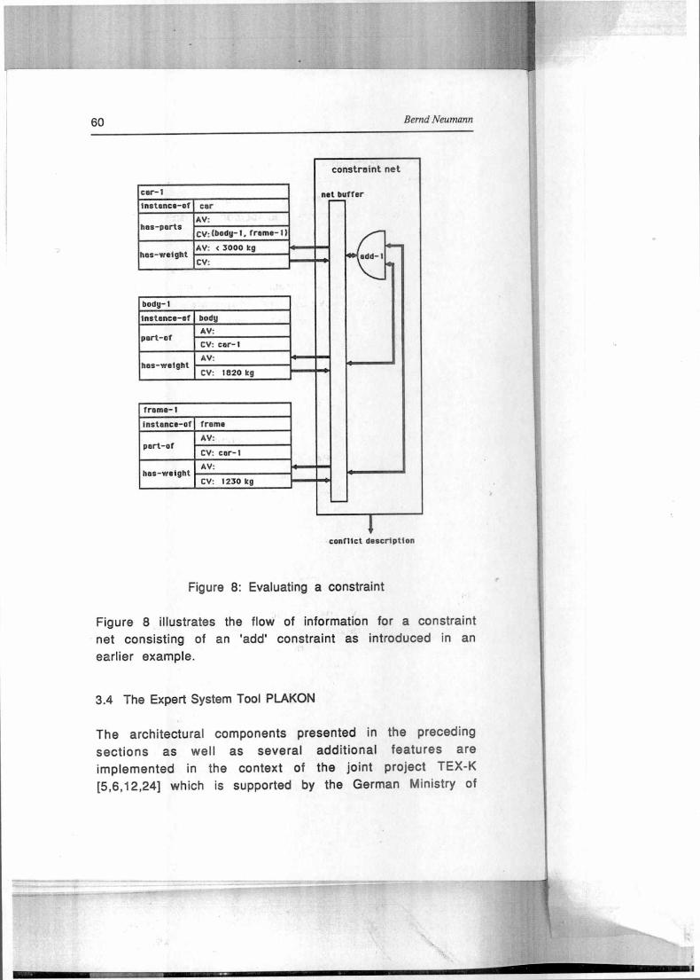
conflict description
Figure 8: Evaluating a constraint
Figure 8 illustrates the flow of information for a constraint
net consisting of an 'add' constraint as introduced in an
earlier example.
3.4 The Expert System Tool PLAKON
The architectural components presented in the preceding
sections as well as several additional features are
implemented in the context of the joint project TEX-K
[5,6,12,24] which is supported by the German Ministry of
configuration Expert Systems 61
Research and Technology (BMFT). The objective of this project
is to develop a tool system - called PLAKON - for planning and
configuration tasks in technical domains. The project has
begun in 1986 and is scheduled until 1989. lt comprises 57
person-years of work shared between five project partners: Battelle Institute (Frankfurt), Philips GmbH (Hamburg),
Siemens AG (Erlangen), URW (Hamburg) and the University of
Hamburg. PLAKON is designed to support diverse applications.
Six applications are implemented in the context of TEX-K:
- configuration of multi-microcomputer systems for
industrial automation (MMC-Kon, see 2.3)
- configuration of computer vision systems for quality
control in manufacturing [23,41]
- configuration of automatic systems for industrial x-ray analysis [27]
- configuration of systems for laboratory experiments
- generating work plans for mechanical manufacturing
- configuration of electrical engineering aggregates using standard components
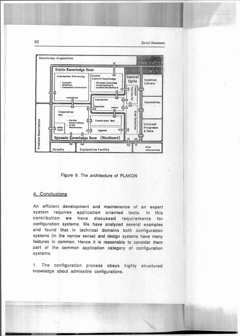
The architecture of PLAKON is shown in Figure 9. The main
properties of the kerne) have been discussed in the preceding
sections leaving out a considerable amount of detail for the sake of conciseness. The peripheral components of PLAKON
which can be seen in the diagram reflect some of the needs
which have become apparent from the discussion of the examples, e.g. a component for library solutions. Details of
these components are still being worked out
Fleberntlon Net
EloEenllen Control
Constraint Hei
1 Agende coroe.
Knowledge Acquisition
Sratic Knowledge Base
Conceptuel Illererchg
- Concept, - Polettons - Contepteel Conot•olnts
tottonttoll.
SIntic Control Knowled
▪
ge
- Str totrolc knowledge - Conotriortl•nol K. - Cunlel Proeletten K. I I
> e
Solution Library
Simulation
Central Cgcle
C i Ta
Exetollen l 1 4
Elgnomto K nowledge Base (Blackboard
Results Explanation racility
External Programs & Date
User Inlerec (Ion
In
mi c
rJ Q
SE
01
CD
E
1
In11141
-
C•notraellono - Tr•th
Holme
62 Bernd Neumann
Figure 9: The architecture of PLAKON
4. Conclusions
An efficient development and maintenance of an expert
system requires application oriented tools. In this
contribution we have discussed requirements for
configuration systems. !Ne have analyzed several examples
and found that in technical domains both configuration
systems (in the narrow sense) and design systems have many
features in common. Hence it is reasonable to consider them
part of the common application category of configuration systems.
1. The configuration process obeys highly structured
knowledge about admissible configurations.

V:"44,44a. ,4111attellte
Configuration Expert Systems
63
2. This knowledge is naturally represented in terms of an is-a
and has-parts knowledge hierarchy with associated
constraints.
3. Configuration requires flexible control and an explicit
representation of control knowledge.
We have proposed a configuration system architecture in
accord with these requirements. Its distinguishing features
are (1) provisions for highly-structured knowledge
representation, (2) configuration steps specified by the
knowledge hierarchy, (3) an independent constraint
propagation system interacting with the knowledge hierarchy,
(4) provisions for a compact representation of the
configuration history, and (5) an explicit representation of
control strategies. Several other features could not be
discussed in detail but are also important, e.g. the
sophisticated use of library solutions [16] or special
techniques for dealing with spatial constraints [4].
A tool for building configuration systems with this
architecture is being developed in project TEX-K and applied
to several different tasks.
5. R f r nce
[1] Bachant, J., McDermott, J.: R1 Revisited: Four Years in the Trenches. The Al Magazine, Vol.5, No.3, AAAI, Menlo Park, California, 1984, 21-32.
[2] Baginsky, W., Endres, H., Geissing, G., Philipp, L.: Basic Architectural Features of Configuration Expert Systems for Automation Engineering. Proc. IEEE-Conference "International Workshop an Artificial Intelligence for Industrial Applications", Hitachi City, 1988. Also TEX-K Report No.11, Energy and Automation Group, Siemens AG, ESTE 12, Erlangen, FRG, 1988.
64 Bernd Neumann
[3] Brachman, R.J., Schmolze, J.G.: Overview of KL-ONE. Cognitive Science Vol.9, No.2, 1985, 171-216.
[4] Baykan, C.A., Fox, M.S.: An Investigation of Opportunistic Constraint Satisfaction In Space Planning. AAAI-87, Morgan Kaufmann, Los Altos, California, 1987, 1035-1038.
[5] Cunis, R., Günter, A., Syska, 1.: Planen mit Plakon. Proc. Workshop Planen, GMD, St. Augustin, FRG, 1987. Also TEX-K Report No.3, Fachbereich Informatik, Universität Hamburg, FRG, 1987.
[6] Cunis, R., Bode, H., Günter, A., Peters, H., Syska, I.: Wissensrepräsentation in PLAKON. TEX-K Report No.10, Fachbereich Informatik, Universität Hamburg, FRG, 1988.
[7] De-Mello, L.S.H., Sanderson, A.C.: AND/OR Graph Representations of Assembly Plans. Proc. AAAI-86, Morgan Kaufmann, Los Altos, California, 1986, 1113- 1119 .
[8] Duffy, A.: Bibliography - Artificial Intelligence in Design. Artificial Intelligence in Engineering, Vol.2, No.3, 1987, 173-179.
[9] Ervin, S.M., Gross, M.D.: RoadLab - A Constraint Based Laboratory for Road Design. Artificial Intelligence in Engineering, Vol.2, No.4, 1987, 224-234.
[10] Fikes, R.E., Nilsson, N.J.: STRIPS: A New Approach to the Application of Theorem Proving to Problem Solving. Artificial Intelligence 2, 1971, 189-208.
[11] Fox, M.S.: Constraint-Directed Search: A Case Study of Job-Shop Scheduling. CMU-RI-TR-83-22, Carnegie Mellon University, Pittsburgh, Pennsylvania, 1983.
[12] Günter, A., Syska, 1., Cunis, R.: PLAKON Anforderungskatalog. TEX-K Report No. 4, Fachbereich Informatik, Universität Hamburg, FRG, 1987.
[13] Güsgen, H.W., Junker, U., Voss, A.: Constraints in a Hybrid Knowledge Representation System. IJCAI-87, Morgan Kaufmann, Los Altos, 1987, 30-33.
Configuration Expert Systems 65
[14] Haugeneder, H., Lehmann, E., Struss, P.: Knowledge-Based Configuration of Operating Systems - Problems in Modeling the Domain Knowledge. Proc. Wissensbasierte Systeme, Springer, Berlin, 1985, 121-134.
[15] Hayes-Roth, T., Waterman, D., Lenat, D. (Eds.): Building Expert Systems. Addison-Wesley, Reading, Massachusetts, 1983.
[16] Huhns, M.S., Ramon, D.A.: Argo: A System for Design by Analogy. Fourth IEEE Conference an Al Applications, Computer Society of the IEEE, Los Angeles, California, 1988, 146-151.
[17] Lehmann, E., Enders, R., Haugeneder, H., Hunze, R., Johnson, C., Schmid, L., Struss, P.: SICONFEX - ein Expertensystem für die betriebliche Konfigurierung eines Betriebssystems. Proc. GI/OCG/ÖGI-Jahrestagung 1985, Springer, Berlin, 1985, 792-805.
[18] Liebowitz, J., Lightfoot, P.: Expert Scheduling Systems: Survey and Preliminary Design Concepts. Applied Artificial Intelligence 1, 1987, 261-283.
[19] Martin, J., Oxman, S.: Building Expert Systems - A Tutorial. Prentice Hall, Englewood Cliffs, New Jersey, 1988.
[20] McDermott, J.: R1: A Rule-Based Configurer of Computer Systems. Artificial Intelligence 19, North-Holland, 1982, 39-88.
[21] Mittal, S., Fraymann, F.: Making Partial Choices in Constraint Reasoning Problems. AAAI-87, Morgan Kaufmann, Los Altos, California, 1987, 631-636.
[22] Mostow, J.: Towards Better Models of the Design Process. The Al Magazine Vol.6, 1985, 44-56.
[23] Neumann, B.: Wissensbasierte Konfigurierung von Bildverarbeitungssystemen. Proc. Mustererkennung 1986, Springer, Berlin, 1986, 206-218.
66
[24] Neumann, B., Cunis, R., Günter, A., Syska, I., Wissensbasierte Planung und Konfigurierung. Proc. Wissensbasierte Systeme 1987, Springer, Berlin, 1987, 347-357.
[25] Nilsson, N.J.: Problem Solving Methods in Artificial Intelligence. McGraw-Hill. New York, 1971.
[26] Oxman, R., Gero, J.S.: Using an Expert System for Design Diagnosis and Design Synthesis. Expert Systems, Vol.4, No.1, 1987, 4-15.
[27] Pfitzner, K., Strecker, H.: XRAY - An Experimental Configuration Expert System for Automatic X-Ray Inspection. Proc. DAGM 1987, Springer, Berlin, 1987, 315-319.
[28] Puppe, F.: Diagnostisches Problemlösen mit dem Expertensystem-Shell MED2. Dissertation, FB Informatik, Universität Kaiserslautern, FRG, 1986.
[29] Raulefs, P.: Knowledge Processing Expert Systems. In Bernold, T., Albers, G. (Eds.): Artificial Intelligence: Towards Practical Applications, North-Holland, Amsterdam, 1985.
[30] Sacerdoti, E.D.: Planning in a Hierarchy of Abstraction Spaces. Artificial Intelligence 5, 1974, 115-135.
[31] Sacerdoti, E.D.: A Structure of Plans and Behavior. American Elsevier, 1977.
[32] Soloway, E., Bachant, J., Jensen, K.: Assessing the Maintainability of XCON-in-RIME: Coping with the Problems of a VERY Large Rule-Base. Proc. AAAI-87, Morgan Kaufmann, Los Altos, California, 1987, 824-829.
[33] Sriram, D.: ALL-RISE: A Case Study in Constraint-Based Design. Artificial Intelligence in Engineering, Vol.2, No.4, 1987, 186-203.
[34] Sriram, D., Maher, M.L.: The Representation and Use of Constraints in Structural Design. Proc. Applications of Artificial Intelligence in Engineering Problems, Springer, Berlin, 1986, 355-368.
Bernd Neumann
Configuration Expert Systems
67
[35] Steel, S.: The Bread and Butter of Planning. Artificial Intelligence Review 1, 1987, 159-181.
[36] Steele, G.L.: The Definition and Implementation of a Computer Programming Language Based on Constraints. Ph.D. Thesis, Al Laboratory, MIT, Cambridge, Massachusetts, 1980.
[37] Steels, L.: The Deepening of Expert Systems. Artificial Intelligence Communications 1, 1987, 9-16.
[38] Steels, L.: Second Generation Expert Systems. Proc. Expertensysteme 87, Konzepte und Werkzeuge, Teubner, 1987, 475-483.
[39] Stefik, M.J.: Planning and Meta-Planning. Artificial Intelligence 16, 1981, 141-170.
[40] Steinberg, L.I.: Design as Refinement Plus Constraint Propagation: The VEXED Experience. AAAI-87, Morgan Kaufmann, Los Altos, California, 1987, 830-835.
[41] Syska, Überlegungen zur automatischen Konfigurierung von industriellen Bildverarbeitungs-systemen. Mitteilung 138, Fachbereich Informatik, Universität Hamburg, 1986.
[42] Tong, C.: Towards an Engineering Science of Knowledge-Based Design. Artificial Intelligence in Engineering, Vol.2, No.3, 1987, 133-166.
[43] van de Brug, A., Bachant, J., McDermott, J.: Doing R1 With Style. Proc. Second IEEE Conference on Al Applications, Computer Society of the IEEE, Los Angeles, California, 1985, 244-249.


![Artificial Intelligence · Artificial Intelligence 2016-2017 Introduction [5] Artificial Brain: can machines think? Artificial Intelligence 2016-2017 Introduction [6] ... Deep Blue](https://static.fdocuments.net/doc/165x107/5f0538917e708231d411e192/artificial-intelligence-artificial-intelligence-2016-2017-introduction-5-artificial.jpg)