
Artifact and Recording Concepts in EEG
12
INVITED REVIEW Artifact and Recording Concepts in EEG William O. Tatum,* Barbara A. Dworetzky,† and Donald L. Schomer† Summary: Artifact is present when electrical potentials that are not brain derived are recorded on the EEG and is commonly encountered during interpretation. Many artifacts obscure the tracing, while others reflect physio- logic functions that are crucial for routine visual analysis. Both physiologic and nonphysiologic sources of artifact may act as source of confusion with abnormality and lead to misinterpretation. Identifying the mismatch between potentials that are generated by the brain from activity that does not conform to a realistic head model is the foundation for recognizing artifact. Electro- encephalographers are challenged with the task of correct interpretations among the many artifacts that could potentially be misleading, resulting in an incorrect diagnosis and treatment that may adversely impact patient care. Despite advances in digital EEG, artifact identification, recognition, and elimination are essential for correct interpretation of the EEG. The authors discuss recording concepts for interpreting EEG that contains artifact. Key Words: EEG, Artifacts, Technology, Identification, Misinterpretation. (J Clin Neurophysiol 2011;28: 252e263) T he EEG is an electrophysiologic test used to understand the functional properties of the brain. Recording electrical potentials on the EEG that are not brain-derived waveforms represents artifact. Artifact is commonly encountered and is an essential component for routine visual analysis of the EEG (Aurlien et al., 2004). While some artifacts “contaminate” the EEG, others reflect physiologic functions that are crucial for a practical clinical correlation. It is the source (Fig. 1) and context of the generator (Fig. 2) that determine a normal or an abnormal feature in clinical use. Eye movements and the electrocardiogram (EKG) produce important artifacts that denote the level of arousal and define the cerebralecardiac relationship. Nevertheless, both physiologic and nonphysiologic sources of arti- fact may act as source of confusion with abnormality and lead to misinterpretation adversely impacting patient care (Benbadis and Tatum, 2003; Krauss et al., 2005). Nonphysiologic artifacts may have multiple sources that require eliminating the interference cre- ated by an electrical generator either by manipulating the instruments of recording after the recording or by modifying the environment during the recording. Physiologic generators require recognizing, identifying, and describing the biologic behavior during the EEG when video is not available to permit an electroclinical correlation. Recording concepts applied to EEG are the foundation for an accurate interpretation and subsequent clinical correlation (Table 1). Because EEG records three-dimensional cerebral sources in two-dimensional fields, the physical and functional factors that govern the believable cerebral fields and polarities of these sources must always be sought to distinguish a physiologic source from artifact. Furthermore, recognizing artifact is a learned experience. It reflects the ability to distinguish a mismatch between an expected electrocerebral potential and one that does not conform to an elec- trophysiologic head model. Waveforms should be localizable, have proper polarity, and possess an electrical field that has a believable cerebral origin. Alternating polarities that do not conform to a cred- ible field in the absence of a skull defect suggest artifact. The elimination of undesirable artifact from the EEG first requires the ability to accurately recognize waveforms as artifact. After recognition, source identification is necessary to implement resolution. Therefore, to obtain an optimal EEG recording, it is crucial that the EEG technologist and electroencephalographer function as a team. By working together to recognize, identify, and eliminate artifact, misinterpretation leading to inappropriate treatment (Benbadis and Tatum, 2003) may be averted. It is with patient care in mind that we discuss the challenges that artifact introduces into routine scalp EEG recording. PRINCIPLES OF DIGITAL RECORDING Microprocessor technology has ushered in new opportunities for the clinical neurophysiologist. Computer-based technology is available for essentially all neurophysiologic procedures but is especially suited to monitoring the EEG. Digitally based EEG monitoring systems are able to undergo acquisition, analysis, management, transfer, and storage of information in a way that is readily accessible (American Clinical Neurophysiology Society, 2006). Evolution of digital EEG has greatly improved the ability to record and display interpretable EEG but possesses both advan- tages and disadvantages (Table 2). Specific benefits include the abil- ity to acquire large quantities of information, remontage, and institute software applications, such as spike and seizure detection programs or quantitative EEG capable of compressed spectral analysis (Young and Campbell, 1999). Disadvantages include the need for technical support, maintenance of equipment, unfamiliarity with the system, and greater cost. Post hoc filtering (Fig. 3), montage selection, adjustment in sensitivity, and alteration of the display speeds enhance the ability to eliminate extracerebral potentials and are not available with ana- logue technology. Digital machines introduce certain computer- generated artifact that necessitates a facility for use and an understanding of computers. Systems that do not allow an adequate sampling rate “alias” and underrepresent electrical potentials (the Nyquist theorem) by producing signal frequencies that are below the true frequency of the waveforms. Most commercially available digital systems, how- ever, account for this and sample at rates .200 samples per second, making aliasing a rare problem with routine recording. Some digital artifact is unique, such as multiplexing artifact, analogueedigital conversion artifact (i.e., the “sticky bit” seen with infrequent From the *Department of Neurology, Mayo Clinic Florida, Jacksonville, Florida, U.S.A.; and †Department of Neurology, Brigham and Women’s Hospital and Harvard Medical School, Boston, Massachusetts, U.S.A. The authors have no conflicts of interest to disclose. Address correspondence and reprint requests to William O. Tatum, DO, Depart- ment of Neurology, Mayo Clinic Florida, 4500 San Pablo Road South, Jacksonville, FL 32224, U.S.A.; e-mail: [email protected]. Copyright Ó 2011 by the American Clinical Neurophysiology Society ISSN: 0736-0258/11/2803-0252 252 Journal of Clinical Neurophysiology Volume 28, Number 3, June 2011 Copyright © North American Neuro-Ophthalmology Society. Unauthorized reproduction of this article is prohibited.
Transcript of Artifact and Recording Concepts in EEG
INVITED REVIEW
Artifact and Recording Concepts in EEG
William O. Tatum,* Barbara A. Dworetzky,† and Donald L. Schomer†
Summary: Artifact is present when electrical potentials that are not brainderived are recorded on the EEG and is commonly encountered duringinterpretation. Many artifacts obscure the tracing, while others reflect physio-logic functions that are crucial for routine visual analysis. Both physiologic andnonphysiologic sources of artifact may act as source of confusion withabnormality and lead to misinterpretation. Identifying the mismatch betweenpotentials that are generated by the brain from activity that does not conform toa realistic head model is the foundation for recognizing artifact. Electro-encephalographers are challenged with the task of correct interpretations amongthe many artifacts that could potentially be misleading, resulting in an incorrectdiagnosis and treatment that may adversely impact patient care. Despiteadvances in digital EEG, artifact identification, recognition, and eliminationare essential for correct interpretation of the EEG. The authors discuss recordingconcepts for interpreting EEG that contains artifact.
Key Words: EEG, Artifacts, Technology, Identification, Misinterpretation.
(J Clin Neurophysiol 2011;28: 252e263)
The EEG is an electrophysiologic test used to understand thefunctional properties of the brain. Recording electrical potentials
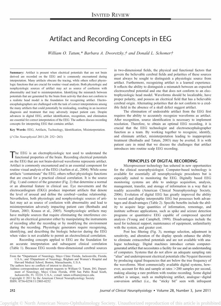
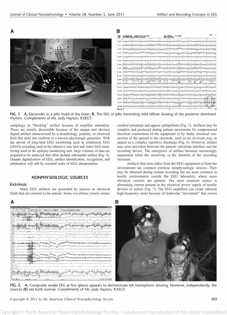
on the EEG that are not brain-derived waveforms represents artifact.Artifact is commonly encountered and is an essential component forroutine visual analysis of the EEG (Aurlien et al., 2004). While someartifacts “contaminate” the EEG, others reflect physiologic functionsthat are crucial for a practical clinical correlation. It is the source(Fig. 1) and context of the generator (Fig. 2) that determine a normalor an abnormal feature in clinical use. Eye movements and theelectrocardiogram (EKG) produce important artifacts that denotethe level of arousal and define the cerebralecardiac relationship.Nevertheless, both physiologic and nonphysiologic sources of arti-fact may act as source of confusion with abnormality and lead tomisinterpretation adversely impacting patient care (Benbadis andTatum, 2003; Krauss et al., 2005). Nonphysiologic artifacts mayhave multiple sources that require eliminating the interference cre-ated by an electrical generator either by manipulating the instrumentsof recording after the recording or by modifying the environmentduring the recording. Physiologic generators require recognizing,identifying, and describing the biologic behavior during the EEGwhen video is not available to permit an electroclinical correlation.
Recording concepts applied to EEG are the foundation foran accurate interpretation and subsequent clinical correlation(Table 1). Because EEG records three-dimensional cerebral sources
in two-dimensional fields, the physical and functional factors thatgovern the believable cerebral fields and polarities of these sourcesmust always be sought to distinguish a physiologic source fromartifact. Furthermore, recognizing artifact is a learned experience.It reflects the ability to distinguish a mismatch between an expectedelectrocerebral potential and one that does not conform to an elec-trophysiologic head model. Waveforms should be localizable, haveproper polarity, and possess an electrical field that has a believablecerebral origin. Alternating polarities that do not conform to a cred-ible field in the absence of a skull defect suggest artifact.
The elimination of undesirable artifact from the EEG firstrequires the ability to accurately recognize waveforms as artifact.After recognition, source identification is necessary to implementresolution. Therefore, to obtain an optimal EEG recording, it iscrucial that the EEG technologist and electroencephalographerfunction as a team. By working together to recognize, identify,and eliminate artifact, misinterpretation leading to inappropriatetreatment (Benbadis and Tatum, 2003) may be averted. It is withpatient care in mind that we discuss the challenges that artifactintroduces into routine scalp EEG recording.
PRINCIPLES OF DIGITAL RECORDINGMicroprocessor technology has ushered in new opportunities
for the clinical neurophysiologist. Computer-based technology isavailable for essentially all neurophysiologic procedures but isespecially suited to monitoring the EEG. Digitally based EEGmonitoring systems are able to undergo acquisition, analysis,management, transfer, and storage of information in a way that isreadily accessible (American Clinical Neurophysiology Society,2006). Evolution of digital EEG has greatly improved the abilityto record and display interpretable EEG but possesses both advan-tages and disadvantages (Table 2). Specific benefits include the abil-ity to acquire large quantities of information, remontage, andinstitute software applications, such as spike and seizure detectionprograms or quantitative EEG capable of compressed spectralanalysis (Young and Campbell, 1999). Disadvantages include theneed for technical support, maintenance of equipment, unfamiliaritywith the system, and greater cost.
Post hoc filtering (Fig. 3), montage selection, adjustment insensitivity, and alteration of the display speeds enhance the abilityto eliminate extracerebral potentials and are not available with ana-logue technology. Digital machines introduce certain computer-generated artifact that necessitates a facility for use and an understandingof computers. Systems that do not allow an adequate sampling rate“alias” and underrepresent electrical potentials (the Nyquist theorem)by producing signal frequencies that are below the true frequency ofthe waveforms. Most commercially available digital systems, how-ever, account for this and sample at rates .200 samples per second,making aliasing a rare problem with routine recording. Some digitalartifact is unique, such as multiplexing artifact, analogueedigitalconversion artifact (i.e., the “sticky bit” seen with infrequent
From the *Department of Neurology, Mayo Clinic Florida, Jacksonville, Florida,U.S.A.; and †Department of Neurology, Brigham and Women’s Hospital andHarvard Medical School, Boston, Massachusetts, U.S.A.
The authors have no conflicts of interest to disclose.Address correspondence and reprint requests to William O. Tatum, DO, Depart-
ment of Neurology, Mayo Clinic Florida, 4500 San Pablo Road South,Jacksonville, FL 32224, U.S.A.; e-mail: [email protected].
Copyright � 2011 by the American Clinical Neurophysiology SocietyISSN: 0736-0258/11/2803-0252
252 Journal of Clinical Neurophysiology � Volume 28, Number 3, June 2011
Copyright © North American Neuro-Ophthalmology Society. Unauthorized reproduction of this article is prohibited.
sampling), or “blocking” artifact because of amplifier saturation.These are usually discernible because of the unique and obviousdigital artifact characterized by a morphology, polarity, or electricalfield that does not conform to a known physiologic generator. Withthe advent of long-term EEG monitoring such as continuous EEG(cEEG) recording used in the intensive care unit and video-EEG mon-itoring used in the epilepsy monitoring unit, large volumes of data areacquired to be analyzed that often include substantial artifact (Fig. 4).Despite digitalization of EEG, artifact identification, recognition, andelimination will still be essential tasks of EEG interpretation.
NONPHYSIOLOGIC SOURCES
ExtrinsicMany EEG artifacts are generated by sources or electrical
fields that are external to the patient. Some waveforms closely mimic
cerebral potentials and appear epileptiform (Fig. 5). Artifacts may becomplex and produced during patient movements by compromisedelectrical connections of the equipment or by faulty electrical con-nection of the patient to the electrode, such as an electrode pop, orappear as a complex repetitive discharge (Fig. 6). However, artifactmay arise anywhere between the patienteelectrode interface and therecording device. The emergence of artifact becomes increasinglyaugmented when the sensitivity or the duration of the recordingincreases.
Artifacts that arise either from the EEG equipment or from theenvironment are common extrinsic nonphysiologic sources. Theymay be obtained during routine recording but are more common inhostile environments outside the EEG laboratory, where moreelectrical currents are present. The most common source isalternating current present in the electrical power supply of nearbydevices or outlets (Fig. 7). The EEG amplifiers can create inherenthigh-frequency noise because of molecular “movement” that occurs
FIG. 1. A, Electrodes in a jello mold of the brain. B, The EEG of Jello mimicking mild diffuse slowing of the posterior dominantrhythm. Compliments of Ms. Judy Hayton, R.EEGT.
FIG. 2. A, Composite awake EEG at first glance appears to demonstrate left hemispheric slowing. However, independently, thesources (B) are both normal. Compliments of Ms. Judy Hayton, R.EEGT.
Journal of Clinical Neurophysiology � Volume 28, Number 3, June 2011 Artifact and Recording Concepts in EEG
Copyright � 2011 by the American Clinical Neurophysiology Society 253
Copyright © North American Neuro-Ophthalmology Society. Unauthorized reproduction of this article is prohibited.
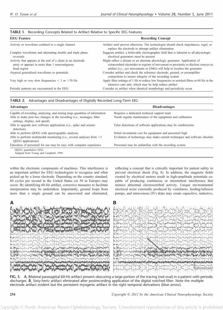
within the electronic components of machines. This interference isan important artifact for EEG technologists to recognize and oftenpicked up by a loose electrode. Depending on the country standard,60 cycles per second in the United States (or 50 in Europe) mayoccur. By identifying 60-Hz artifact, corrective measures to facilitateinterpretation may be undertaken. Importantly, ground loops frommore than a single ground can be uncovered and eliminated,
reflecting a concept that is critically important for patient safety toprevent electrical shock (Fig. 8). In addition, the magnetic fieldscreated by electrical motors result in high-amplitude potentials ca-pable of producing continuous or intermittent interference thatmimics abnormal electrocerebral activity. Unique environmentalelectrical noise externally produced by ventilators, feeding/infusionpumps, and intravenous (IV) drips may create capacitive, inductive,
TABLE 1. Recording Concepts Related to Artifact Relative to Specific EEG Features
EEG Feature Recording Concept
Activity or waveform confined to a single channel Artifact until proven otherwise. The technologist should check impedances, regel, orreplace the electrode to attempt artifact elimination
Complex waveforms and alternating double and triple phasereversals
Suggests artifact: a believable electrographic field that is inherent to all physiologicelectrical generators must be present
Activity that appears at the end of a chain in an electrodearray or appears in more than 1 noncontiguoushead region
Might reflect a distant or an alternate physiologic generator. Application ofextracerebral electrodes to regions of movement or proximity to disclose sources asartifact (i.e., eye movements or EMG) will help to localize the generator
Atypical generalized waveforms or potentials Consider artifact and check the reference electrode, ground, or preamplifierconnections to ensure integrity of the recording system
Very high or very slow frequencies , 1 or .70 Hz Apply filter settings of 1 Hz to reduce low frequencies or notched filters at 60 Hz in theintensive care unit, which may be help reduce artifact
Periodic patterns are encountered in the EEG Consider as artifact when identical morphology and periodicity occur
TABLE 2. Advantages and Disadvantages of Digitally Recorded Long-Term EEG
Advantages Disadvantages
Capable of recording, analyzing, and storing large quantities of information Requires a dedicated technical support teamAble to make post hoc changes in the recording (i.e., montages, filter
settings, display, and speed)Needs regular maintenance of the equipment and calibration
Able to upgrade new software applications (i.e., spike and seizuredetection)
False detections of software applications may be cumbersome
Able to perform QEEG with spectrographic analyses Initial investment cost for equipment and personnel highAble to perform multimodal monitoring (i.e., several analyses from .1
QEEG applications)Evolution of technology may make current techniques and software obsolete
Education of personnel for use may be easy with computer experience Personnel may be unfamiliar with the recording system
QEEG, quantitative EEG.Adapted from Young and Campbell, 1999.
FIG. 3. A, Bilateral parasagittal 60-Hz artifact present obscuring a large portion of the tracing (red oval) in a patient with periodicdischarges. B, Sixty-hertz artifact eliminated after postrecording application of the digital notched filter. Note the multipleelectrode artifact evident but the persistent myogenic artifact in the right temporal derivations (blue arrow).
W. O. Tatum et al. Journal of Clinical Neurophysiology � Volume 28, Number 3, June 2011
254 Copyright � 2011 by the American Clinical Neurophysiology Society
Copyright © North American Neuro-Ophthalmology Society. Unauthorized reproduction of this article is prohibited.
and electrostatic artifacts not commonly seen on routine recording.Through direct observation, repeat impedance checks, and reappli-cation of the ground or surface electrodes when disrupted may val-idate source recognition and quick correction of artifact.
EquipmentThe most common artifacts are because of an insecure
connection between the electrodes and the machine (Reilly, 1999).When activity is confined to two channels on a bipolar recording orone channel on a referential recording montage (without an electricalfield), the electrode artifact should be suspected and individual elec-trode impedances should be retested. Similarly, complex waveformsshould always raise the suspicion of an artifact. Electrode artifactsare usually recognizable and eliminated by replacing or resecuring
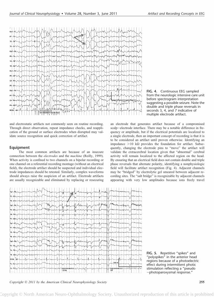
an electrode that generates artifact because of a compromisedscalpeelectrode interface. There may be a notable difference in fre-quency or amplitude, but if the electrical potentials are localized toa single electrode, then an important concept of recording is that it isto be considered an artifact until proven otherwise. Identifying animpedance .10 kU provides the foundation for artifact. Subse-quently, changing the electrode pins to “move” the artifact willvalidate the extracerebral location given that “abnormal” cerebralactivity will remain localized to the affected region on the head.By ensuring that an electrical field does not contain double and triplephase reversals that alternate polarity, identifying a nonphysiologicfield will facilitate artifact recognition (Fig. 4). Adjacent channelsmay be “bridged” by electrolytic gel smeared between adjacent re-cording sites. The “salt bridge” is recognizable by adjacent channelsappearing with very low amplitudes because ions freely travel
FIG. 4. Continuous EEG sampledfrom the neurologic intensive care unitbefore spectrogram interpretationsuggesting a possible seizure. Note thedouble and triple phase reversals inseconds 3, 4, and 7 indicative ofmultiple electrode artifact.
FIG. 5. Repetitive “spikes” and“polyspikes” in the anterior headregions because of a photoelectriceffect during intermittent photicstimulation reflecting a “pseudoephotoparoxysmal response.”
Journal of Clinical Neurophysiology � Volume 28, Number 3, June 2011 Artifact and Recording Concepts in EEG
Copyright � 2011 by the American Clinical Neurophysiology Society 255
Copyright © North American Neuro-Ophthalmology Society. Unauthorized reproduction of this article is prohibited.
between the electrodes and in essence zero out the recorded differ-ences between the electrocerebral activities.
High-impedance electrodes are especially common duringEEG recordings in the intensive care unit and operating room,known as electrically “hostile environments.” Interference fromnearby power lines can introduce “noise” into the biologic signals.By abrading the skin and with adequate use of electrolyte gel,a scalpeelectrode biologic resistance (impedance) may be mini-mized. If there is an electrode mismatch of .5 kU through eitherlimited abrasion (the epidermis has high impedance) or incompleteelectrode contact with the scalp, then the discordant input to theamplifiers facilitates a greater risk for 60-cycle artifact. When diffuse60-Hz artifact is encountered, then the integrity of the ground shouldbe reassessed. In addition, ensuring proper patientemachine connec-tions ensures that the integrity of patient safety has not been com-promised. Supplemental use of filters, including a 60-Hz notchedfilter, can be applied to diminish artifact at discrete bandwidthsduring post hoc review.
EnvironmentNonphysiologic artifact requires locating the source when
possible, either by adjusting the instruments of recording or bymodifying the environment where EEG is recorded. Environmentalartifacts remain some of the most difficult to eliminate despiteidentification and correct source recognition. Many are beyond thetechnologist’s control to adjust. Inductive, electrostatic, and
capacitive artifacts may occur during the course of acquiring EEGfrom the patient through essential electrical wires that monitor otherfunctions in addition to the EEG machine (Klem, 2003). Radio fre-quencies from nearby mechanical pumps or electrical devices inspecial care units can introduce intermittent or continuous high-fre-quency artifact. Electrical motors in beds, adjacent IV machines,tube feeding delivery systems, or other devices may create artifactthat is difficult to identify or alter (Fig. 9). Inductive artifact mayoccur from electrical potentials created by IV macrodrip sourcesduring droplets that conduct potentials via electrostatic forces fromadjacent electrical wiring to the recorded EEG. This may give thefalse appearance of an epileptiform-appearing spike, polyspike,sharp transient, or paroxysmal burst, evident in a few or in multiplechannels. The synchrony of the EEG potentials with another source,such as IV drip, validates the extracerebral source. Static electricitymay be generated by clothing, linen, or the patient who may intro-duce artifact by electrical input introduced into nearby wiring orrecording electrodes. This may subsequently create “pseudo-spikes”with complex morphologies and noncerebral distributions and fields.The representation of a regular, rapid, rhythmic burst as artifact isusually betrayed by the very brief duration and regularity. In addi-tion, the electrode cable can act as a capacitor because of the multipleinsulated wires that are contained within a single cable. Subsequentmovement of the cable is able to generate waveforms that simulateinterictal epileptiform discharges (IEDs) (Fig. 10). Closer inspectionof these potentials will usually reveal a noncerebral field or wave-form polarity.
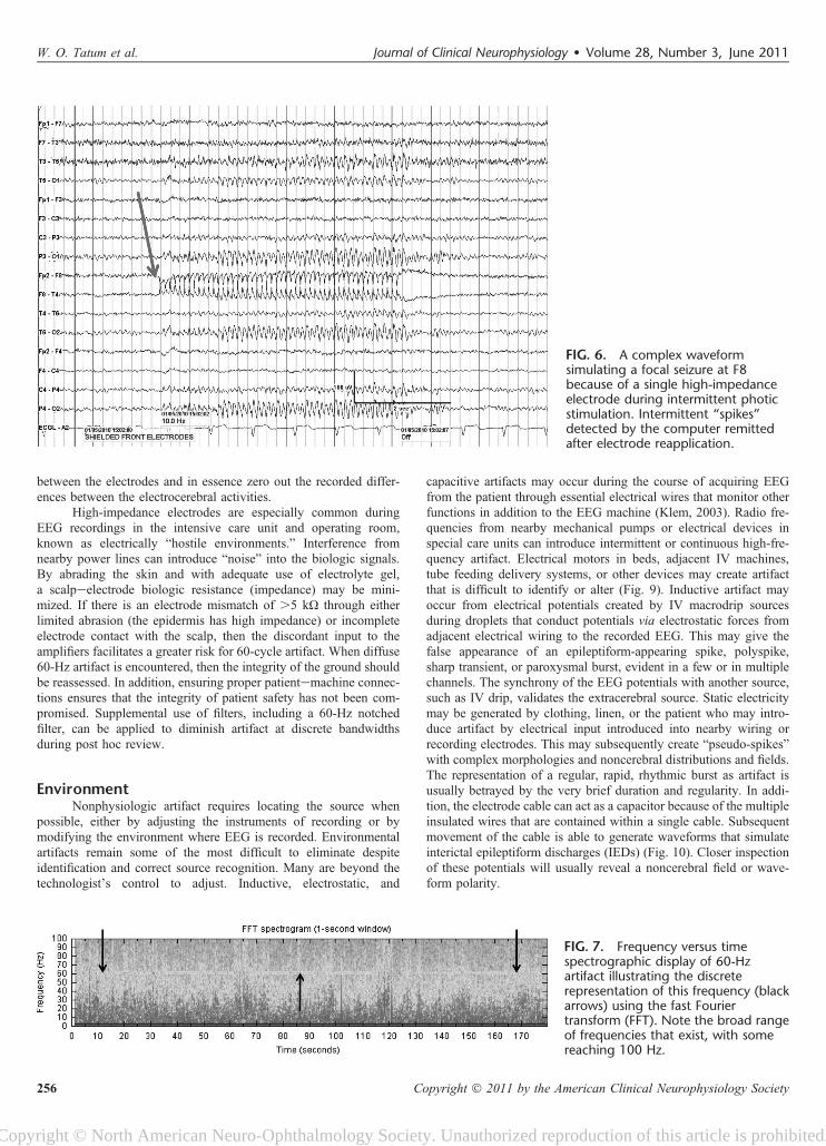
FIG. 6. A complex waveformsimulating a focal seizure at F8because of a single high-impedanceelectrode during intermittent photicstimulation. Intermittent “spikes”detected by the computer remittedafter electrode reapplication.
FIG. 7. Frequency versus timespectrographic display of 60-Hzartifact illustrating the discreterepresentation of this frequency (blackarrows) using the fast Fouriertransform (FFT). Note the broad rangeof frequencies that exist, with somereaching 100 Hz.
W. O. Tatum et al. Journal of Clinical Neurophysiology � Volume 28, Number 3, June 2011
256 Copyright � 2011 by the American Clinical Neurophysiology Society
Copyright © North American Neuro-Ophthalmology Society. Unauthorized reproduction of this article is prohibited.
IntrinsicInternal interference because of biologically active magnetic
fields induced by cardiac (i.e., pacemakers or assist devices) orneurologic (i.e., neurostimulators) devices may contribute to a varietyof artifacts that challenge the reader. For correct identification, regularityis the key, and regularity is the key to their recognition, independent ofmorphology. Cardiac pacemakers are medical devices that use electricalimpulses to regulate heart rhythm and may be an intrinsic non-physiologic source of electrical artifact on the EEG. Some permanentpacemakers may be combined with an implantable defibrillator and
produce high-voltage, repetitive, brief electrical potentials that appearperiodically or continuously depending on the mode of stimulusdelivered. When pacemaker-generated artifact is present, EKG artifactmay be misinterpreted as periodic lateralized epileptiform discharges inthe EEG (Fig. 11). Both continuous and on-demand mode pacemakersusing either single- or dual-chambered stimulation help resynchronizethe left ventricular outflow in patients with heart failure or cardiacarrhythmias (Cleland et al., 2005; Gregoratos et al., 1998) but act asa source of artifact (Fig. 11). Other electrical devices, such asvagus nerve stimulators, deep brain stimulators, and responsive
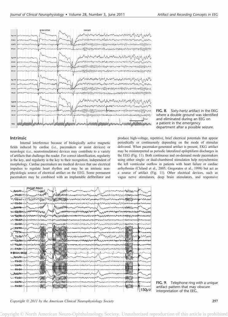
FIG. 8. Sixty-hertz artifact in the EKGwhere a double ground was identifiedand eliminated during an EEG ona patient in the emergencydepartment after a possible seizure.
FIG. 9. Telephone ring with a uniqueartifact pattern that may obscureinterpretation of the EEG.
Journal of Clinical Neurophysiology � Volume 28, Number 3, June 2011 Artifact and Recording Concepts in EEG
Copyright � 2011 by the American Clinical Neurophysiology Society 257
Copyright © North American Neuro-Ophthalmology Society. Unauthorized reproduction of this article is prohibited.
neurostimulators, may create artifact. This may occur when electroniccircuitry is surgically implanted and produces undesirable signals thatinternally affect the EEG. In this way, the unshielded EEG electrodesact as an antenna for extracerebral sources of stimulator-induced elec-trical fields to produce artifact. This is similar to the extraneous effectcreated by nearby power lines to generate 60-Hz interference throughinduction of magnetic fields from nearby electrical current flow causingelectrode depolarization and resultant noise (Tatum, 2008).
PHYSIOLOGIC SOURCES
Routine RecordingIdentifying the mismatch between potentials that are gener-
ated by the brain from activity that does not conform to a realistichead model is the foundation for recognizing artifact. The means tojudge the mismatch is based on a believable localization, polarity,and field. The technologist helps monitor, eliminate, or camouflagethe extracerebral sources when bioelectric fields introduce artifacts
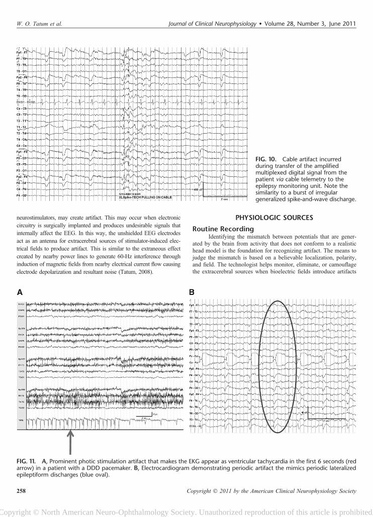
FIG. 10. Cable artifact incurredduring transfer of the amplifiedmultiplexed digital signal from thepatient via cable telemetry to theepilepsy monitoring unit. Note thesimilarity to a burst of irregulargeneralized spike-and-wave discharge.
FIG. 11. A, Prominent photic stimulation artifact that makes the EKG appear as ventricular tachycardia in the first 6 seconds (redarrow) in a patient with a DDD pacemaker. B, Electrocardiogram demonstrating periodic artifact the mimics periodic lateralizedepileptiform discharges (blue oval).
W. O. Tatum et al. Journal of Clinical Neurophysiology � Volume 28, Number 3, June 2011
258 Copyright � 2011 by the American Clinical Neurophysiology Society
Copyright © North American Neuro-Ophthalmology Society. Unauthorized reproduction of this article is prohibited.
that limit interpretation during routine EEG recording (Klass, 1995).Physiologic sources of artifacts are often encountered during routinerecording and include ocular, orobuccal, cardiac, and myogenic anddefects of the cranial bone structures.
Eye movement artifacts are seen in virtually every consciousindividual during routine EEG and are crucial to correctly identifydifferent stages of sleep. Vertical eye blink artifact during wakeful-ness, slow rolling eye movement artifact in drowsiness, and rapid
eye movement artifact in rapid eye movement sleep are essential todiscern normal levels of arousal. Eye movement artifact on EEG isgenerated by an inherent corneoretinal resting potential. An electricaldipole normally exists in most biologic tissue, including the eye. Thecornea is electropositive relative to the retina and generates a directcurrent potential difference that can be measured in the horizontal orvertical plane. An electrooculogram is constructed quickly and easilyby applying electrodes above and below the eye (Fig. 12). These use
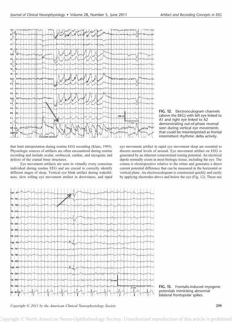
FIG. 12. Electrooculogram channels(above the EKG) with left eye linked toA1 and right eye linked to A2demonstrating out-of-phase reversalseen during vertical eye movementsthat could be misinterpreted as frontalintermittent rhythmic delta activity.
FIG. 13. Frontalis-induced myogenicpotentials mimicking abnormalbilateral frontopolar spikes.
Journal of Clinical Neurophysiology � Volume 28, Number 3, June 2011 Artifact and Recording Concepts in EEG
Copyright � 2011 by the American Clinical Neurophysiology Society 259
Copyright © North American Neuro-Ophthalmology Society. Unauthorized reproduction of this article is prohibited.
one to four channels that help differentiate cerebral potentials that arein phase with extracerebral potentials that are out of phase (Bonnetet al., 1992). In-phase deflections characterize cerebral dipoles (ora generator below the electrodes), and out-of-phase deflections occurwith eye movement artifact reflecting a generator location that liesbetween the recording electrodes. Horizontal and skew eye
movements are best identified when opposite polarities for phasereversal are noted at the F7/F8 derivation. It is the positive slow-wave phase reversal during conjugate horizontal eye movements thatreflects the site closest to the cornea signifying the direction of gaze.
Myogenic (muscle) artifact is another commonly observedartifact on EEG. The temporalis and frontalis are the principal
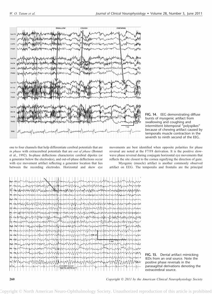
FIG. 15. Dental artifact mimickingIEDs from an oral source. Note thepositive phase reversals in theparasagittal derivations denoting theextracerebral source.
FIG. 14. EEG demonstrating diffusebursts of myogenic artifact fromswallowing and coughing andintermittent bitemporal “polyspikes”because of chewing artifact caused bytemporalis muscle contraction in theseventh to ninth second of the EEG.
W. O. Tatum et al. Journal of Clinical Neurophysiology � Volume 28, Number 3, June 2011
260 Copyright � 2011 by the American Clinical Neurophysiology Society
Copyright © North American Neuro-Ophthalmology Society. Unauthorized reproduction of this article is prohibited.
muscles that produce myogenic artifact on EEG (Fig.13). Duringrecording, by asking a patient to “open your mouth” may help alle-viate bitemporal myogenic artifact incurred from contraction of themasseter muscles or with jaw clenching. Lateral rectus “spikes” mayappear during eye movements and simulate IEDs (see Fig. 11).These represent motor unit potentials of extracerebral originrecorded from the lateral recti and other muscles of the globe thatare proximate to the lateral orbit and are best identified in the F7/F8derivations. A slow potential because of the higher amplitude directcurrent may be created by an active dipole during eye movements.The appearance together of the lateral rectus spike and direct currentpotential mimics a spike-and-wave that may lead to an erroneousinterpretation of the EEG. Similar to the lateral rectus spikes seen
with rapid eye movements, frontalis muscle contraction during peri-ocular movement may elicit sustained or individual myogenic poten-tials that mimic IEDs (Klem, 2003). Activation with intermittentphotic stimulation, or eye flutter artifact elicited at frequenciesof ,6 Hz, may mimic generalized spike-and-wave when coupledwith myogenic potentials and create a “pseudoephotoparoxysmalresponse” (Fig. 5A) with muscle spikes time-locked to the flashfrequency. Newer techniques of muscle artifact removal may helpimprove the interpretation of the ictal scalp EEG (De Clercq et al.,2005). However, a pitfall that exists is that it can render a recordmore rhythmic in appearance.
Cardiac muscle is another important source of EEG artifact.Recording the EKG during an EEG is essential to monitor the
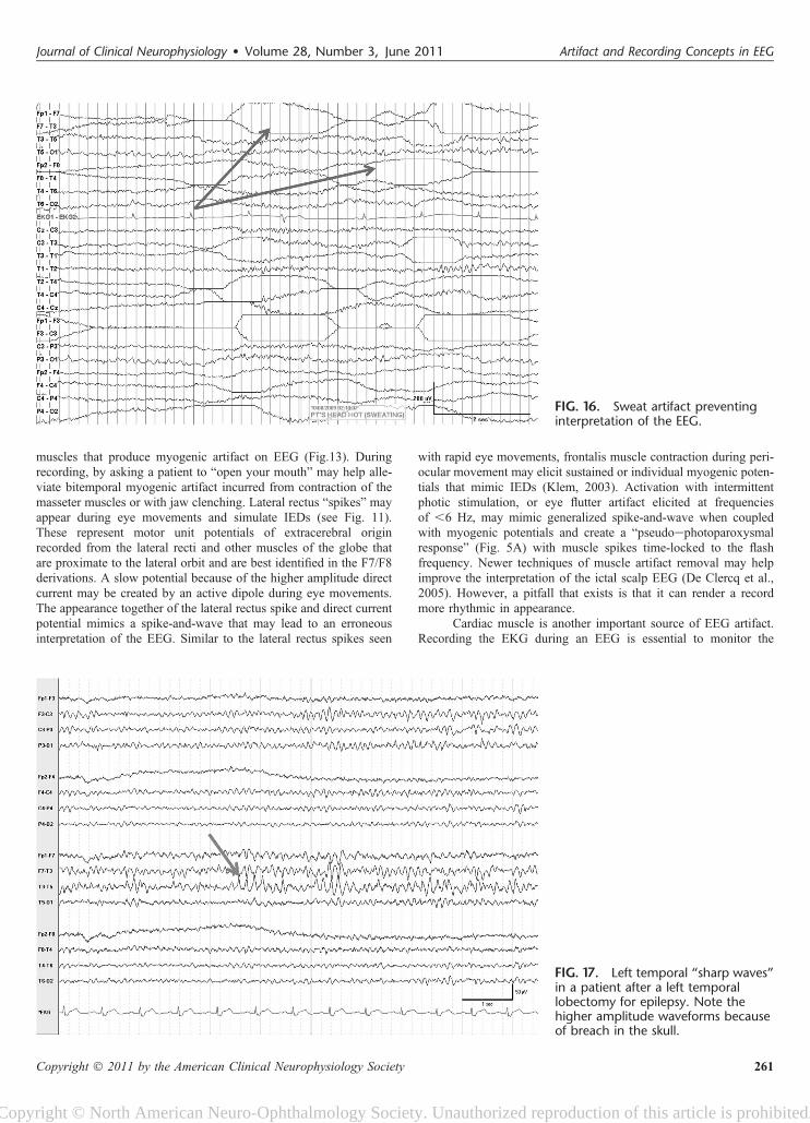
FIG. 17. Left temporal “sharp waves”in a patient after a left temporallobectomy for epilepsy. Note thehigher amplitude waveforms becauseof breach in the skull.
FIG. 16. Sweat artifact preventinginterpretation of the EEG.
Journal of Clinical Neurophysiology � Volume 28, Number 3, June 2011 Artifact and Recording Concepts in EEG
Copyright � 2011 by the American Clinical Neurophysiology Society 261
Copyright © North American Neuro-Ophthalmology Society. Unauthorized reproduction of this article is prohibited.
cardiacecerebral relationship. Channel I of the EKG is approximatedon the chest by electrodes linking the left and the right thoraxes.Bipolar recording identifies the QRS complex as the spread of elec-trical activity within the ventricular myocardium. Periodic EKG ar-tifact may appear in the EEG that may mimic an IED or a periodiclateralized epileptiform discharge, although the amplitude and regu-larity make it easy to recognize (Fig. 11). Bipolar montages mayreveal “focal” diphasic waveforms in the temporal derivations of theleft hemisphere because of the vector created by the electrical con-duction of the left ventricle generating the QRS complex. Oppositepolarities of the R wave from the EKG may be seen at the left(negative) and the right (positive) ear electrodes. The artifact pro-duced by the EKG should be readily identifiable by the regularityand periodicity synchronizing EEG with the EKG. Referential mon-tages often accentuate EKG artifact, especially with ear references orlonger interelectrode distances. Additionally, periodic epileptiformdischarges may be more likely suspected when high sensitivities(i.e., electrocerebral inactivity recordings recordings) are used.Patients who are overweight or have short stocky necks may bepredisposed to this type of EKG artifact because the QRS complexis amplified. Reduction in EKG artifact may be possible if the tech-nologist is able to alter the position of the head and neck. Alterna-tively, linking the ears as a reference may cancel the EKG artifactproduced by cardiac muscle contraction and the resultant electricalpotential that is produced. Additional artifacts produced by the heartinclude pulse artifact or movement-generated (ballistocardiographic)artifact that arises from the mechanical force of contraction. Theseusually arise in a single channel with pulse artifact but may give riseto a lateralized or diffuse rhythmic slow wave after the QRS complexthat is typically time-locked by 200 milliseconds. Stabilizing thehead with towels under the neck often eliminates this problem whenhead movement is the generator. Similarly, when an electrode ispositioned over an artery and produces pulse artifact, it may produceperiodic waveforms that are time-locked to the cardiac rhythm. Elim-ination of the artifact can be obtained by pressing or moving theelectrode to an adjacent region on the scalp away from the artery.
Glossokinetic or tongue movements may create significantartifact in the EEG (Fig. 14). Similar to the eye, the tongue is a bio-electric dipole, with the tip of the tongue negative relative to the root.During oropharyngeal motion, a direct current potential is producedthat is often diffusely seen with frontal and temporal predominance.Cephaladecaudad motions may be produced by tongue movementsinvoluntarily while speaking or when swallowing and mimic intermit-tent bursts of abnormal slowing or frontal intermittent rhythmic deltaactivity on the EEG. However, similar artifact may be reproducedwhen asked to say “lilt” or “tatata, lalala, gagaga” identifying similarpatterns as artifact more conclusively. Validation is possible throughapplication of tongue movement monitors with electrodes placedabove and below the mouth over the cheek and chin. Using a bipolarmontage, opposite phase reversals are evident with tongue movementin a similar fashion to those recorded during eye movements. Dentalartifact may mimic spikes because of electrical properties created bymetal amalgam that is used for filling caries (Fig. 15).
Physiologic respiratory artifacts are crucial to observe duringEEG. Respiratory artifacts will allow sleepewake differentiationrelative to “spells” in infants and young children with abnormalevents during sleep or rapid latency/frequency of sleep transitioning.In adults, sleep-related movements, such as snoring, periodic legmovements, myoclonic jerks, and arousal patterns, may be suggestedby the pattern of myogenic or movement artifact that appears on theEEG. Sweat artifact will have very slow (0.25 to 0.50 Hz) anddetectable appearances that are readily identifiable obscuring
underlying cerebral rhythms (Fig. 16). Rhythmic artifact may alsobe encountered in the EEG and become lateralized or generalizeddepending on the source. Amplitudes from movement monitors willbe of greater amplitude than those recorded from the scalp. The time-locked synchrony of a movement with the appearance of a waveformon the EEG will become evident, suggesting artifact. If this occursduring sleep, then a definitive investigation may be obtained withovernight polysomnography.
Other sources, such as bone, may introduce artifact withrhythms because of a focal electrophysiologic breach caused by analtered architecture of the skull or by artificial bone that maybecome overinterpreted as focal IEDs (Fig. 17). The breach effectis best exemplified using bipolar recordings to permit better spatialcontrast. EMG artifact at the breach is readily differentiated by thepresence of the “abnormality” at a location that overlies a commonmuscle (i.e., temporalis or frontalis), by higher frequency compo-nents (duration of spikes ,20 milliseconds) caused by the motorunit potentials, and by the inconsistent appearance thatis minimized or eliminated during sleep or with special maneu-vers, such as jaw relaxation.
The major and the most important physiologic artifacts inEEG are cardiac and ocular sources. Polygraphic recording withsimultaneous monitoring of several physiologic systems and behav-ioral variables may help accurately represent the EEG by illustratingartifact. During bipolar recording, extra electrodes may be appliedseveral inches from a suspected source of artifact to help monitor anddocument motor movements if they are present. Tremor-inducedartifact may even raise a differential diagnosis based on frequencyand amplitude characteristics that can be more attributable to a spe-cific tremor, such as those of Parkinsonian (usually slower andhigher amplitude) origin.
Recording SitesSome areas in the hospital are electrically complex (hostile
environments) and are predisposed to forming artifacts (Ebersole,2003). The most common source of electrical artifact is because ofalternating current from nearby power supplies, devices, or outlets thatcreate 60-Hz interference of EEG interpretation and are the norms inspecial care units. The magnetic fields created by electrical motorsmay also result in high-amplitude potentials that are continuous orintermittent. The distribution may be diffuse or focal and restrictedto a single channel. Both extrinsic and intrinsic electrical noise canresult in artifact that may obscure the EEG and mimic IEDs. Externalelectrical noise produced environmentally by ventilators, feeding/infusion pumps, and IV drip may create capacitance, inductance,and electrostatic artifacts. Internal interference because of biologicallyactive magnetic fields may be introduced by ventricular assist devices,cardiac pacemakers, and neurostimulators that contribute to a varietyof artifacts. About recording concepts, intermittency is the rule, andregularity the clue to identifying artifact regardless of the morphology.Technologists trained to recognize, identify, and eliminate artifactwhen it is encountered are critical to optimize a recording. Applicationof additional extracerebral monitors, repositioning, directing accept-able electrical modification, and documenting medication administra-tion during the recording provide crucial information for aninterpretation where clinical correlation is intuitive.
CONCLUSIONSMany nonphysiologic and physiologic artifacts are encountered
in the process of recording EEG (Stern and Engel, 2005). Someartifacts are essential to understand functions of the brain; however,
W. O. Tatum et al. Journal of Clinical Neurophysiology � Volume 28, Number 3, June 2011
262 Copyright � 2011 by the American Clinical Neurophysiology Society
Copyright © North American Neuro-Ophthalmology Society. Unauthorized reproduction of this article is prohibited.
many artifacts are not and limit useful interpretation of the EEG.Identifying and recognizing artifact to “troubleshoot” and eliminateor camouflage sources of artifact requires a coordinated team com-posed of technologists, nursing, personnel experienced in informat-ics, and neurophysiologists to ensure optimal EEG recordings. TheAmerican Society of Electroneurodiagnostic Technologists, Inc, inconjunction with the Board of Registration for Electroencephalo-graphic and Evoked Potential Technologists has set standards for re-cording EEG. The American Clinical Neurophysiology Society inconjunction with the American Board of Clinical Neurophysiologistshas established guidelines for physician interpretation and reporting.With the unique and complex nature imposed by the many artifactsthat exist, even “seasoned” technologists and electroencephalogra-phers will still be challenged to recognize every artifact that mayjeopardize correct interpretation of the EEG for clinical correlation.
ACKNOWLEDGMENTThe authors wish to thank Dr. Susan Herman for her
contribution to this work.
REFERENCESAmerican Clinical Neurophysiology Society. Guideline 8: Guidelines for recording
clinical EEG in digital media. J Clin Neurophysiol 2006;23:122e124.Aurlien H, Gjerde IO, Aarseth JH, et al. EEG background activity described by
a large computerized database. Clin Neurophysiol 2004;115:665e673.Benbadis SR, Tatum WO. Overinterpretation of EEGs and misdiagnosis of epi-
lepsy. J Clin Neurophysiol 2003;20:42e44.
Bonnet M, Carley D, Carskadon M, et al. EEG arousals: scoring rules and exam-ples. Sleep 1992;15:173e184.
Cleland JG, Daubert JC, Erdmann E. The effect of cardiac resynchronization onmorbidity and mortality in heart failure. N Engl J Med 2005;352:1539e1549.
De Clercq W, Vergult A, Vanrumste B, et al. A new muscle artifact removaltechnique to improve the interpretation of the ictal scalp electroencephalo-gram. Conf Proc IEEE Eng Med Biol Soc 2005;1:944e947.
Ebersole JS. Cortical generators and EEG voltage fields. In: Ebersole JS, PedleyTA, eds. Current practice of clinical electroencephalography. 3rd ed. Phil-adelphia, PA: Lippincott Williams & Wilkins; 2003:12e31.
Gregoratos G, Cheitlin MD, Conill A, et al. ACC/AHA guidelines for implantationof cardiac pacemakers and antiarrhythmia devices: a report of the ACC/AHATask Force on Practice Guidelines (Committee on Pacemaker Implantation).J Am Coll Cardiol 1998;31:1175e1206.
Klass DW. The continuing challenge of artifacts in the EEG. Am J EEG Technology1995;35:239e269.
Klem GH. Artifacts. In: Current practice of clinical electroencephalography.3rd ed. Philadelphia, PA: Lippincott Williams & Wilkins; 2003:271e287.
Krauss G, Abdallah A, Lesser R, et al. Clinical and EEG features of patientswith EEG wicket rhythms misdiagnosed with epilepsy. Neurology2005;64:1879e1883.
Maybaum S, Mancini D, Xydas S, et al.for the LVAD Working Group. Cardiacimprovement during mechanical circulatory support: a prospective multicen-ter study of the LVAD Working Group. Circulation 2007;115:2497e2505.
Reilly EL. EEG recording and operation of the apparatus. In: Niedermeyer E,Lopes Da Silva F, eds. Electroencephalography: basic principles, clinicalapplications, and related fields. 4th ed. Philadelphia, PA: LippincottWilliams & Wilkins; 1999:122e142.
Stern JM, Engel J Jr. Atlas of EEG patterns. Philadelphia, PA: LippincottWilliams & Wilkins; 2005:55e86.
Tatum WO. Normal EEG. In: Tatum WO, Husain A, Benbadis SR, Kaplan PW,eds. Handbook of EEG interpretation. New York: Demos; 2008:1e50.
Young GB, Campbell VC. EEG monitoring in the intensive care unit: pitfalls andcaveats. J Clin Neurophysiol 1999;16:40e45.
Journal of Clinical Neurophysiology � Volume 28, Number 3, June 2011 Artifact and Recording Concepts in EEG
Copyright � 2011 by the American Clinical Neurophysiology Society 263
Copyright © North American Neuro-Ophthalmology Society. Unauthorized reproduction of this article is prohibited.