Articulation of bridges and the design of substructure
47
7 Articulation of bridges and the design of substructure 7.1 General Concrete bridges expand and contract with temperature changes, they shorten under the effects of concrete shrinkage and creep and they deflect under the effect of applied loads, prestress and temperature gradients. The deck must be held in place when subjected to wind, seismic activity and to forces applied by the traffic carried. If the deck is long, it may be necessary to divide it into several expansion lengths by intermediate joints. The articulation of a bridge may be defined as all the measures taken to hold it firmly in position while allowing it to change in length and width and to rotate at supports. The articulation interacts closely with the type of bridge deck chosen, with the method of construction of the deck and with the design of the foundations. It cannot be considered in isolation; it is part of the overall concept of the bridge and should be present in the first ‘back of the envelope’ schemes. 7.2 Design parameters 7.2.1 Temperature change Concrete bridge decks have considerable thermal inertia, and so do not follow daily extremes of temperature. The bridge deck temperatures which should be considered are defined by the local codes of practice. For instance, in the London area of the UK it is accepted that the temperature of a concrete bridge may vary from –7°C in winter to +36°C in summer, while in an equatorial climate such as that relevant to Kuala Lumpur, for instance, there are no significant seasons, and designers use bridge temperatures of 30 ± 10°C. One cannot of course expect that the bridge will be built at the mean temperature; consequently it is necessary to consider carefully the actual range for which the arti- culation should be designed. This may not be the same for all parts of the structure. For instance, consider a bridge built in the London area consisting of several continuous spans, with the deck built into the piers, and erected by balanced cantilever. While the balanced cantilever is under construction, it is free to expand and contract with changing temperature without any bending moments being created. Once it is connected to the adjacent balanced cantilever it becomes a portal and expansion and contraction of the spans due to temperature change will cause bending moments in
Transcript of Articulation of bridges and the design of substructure

7Articulation of bridges and the design of substructure
7.1 General
Concrete bridges expand and contract with temperature changes, they shorten under
the effects of concrete shrinkage and creep and they defl ect under the effect of
applied loads, prestress and temperature gradients. The deck must be held in place
when subjected to wind, seismic activity and to forces applied by the traffi c carried.
If the deck is long, it may be necessary to divide it into several expansion lengths by
intermediate joints. The articulation of a bridge may be defi ned as all the measures
taken to hold it fi rmly in position while allowing it to change in length and width and
to rotate at supports.
The articulation interacts closely with the type of bridge deck chosen, with the
method of construction of the deck and with the design of the foundations. It cannot
be considered in isolation; it is part of the overall concept of the bridge and should be
present in the fi rst ‘back of the envelope’ schemes.
7.2 Design parameters
7.2.1 Temperature change
Concrete bridge decks have considerable thermal inertia, and so do not follow daily
extremes of temperature. The bridge deck temperatures which should be considered
are defi ned by the local codes of practice. For instance, in the London area of the
UK it is accepted that the temperature of a concrete bridge may vary from –7°C in
winter to +36°C in summer, while in an equatorial climate such as that relevant to
Kuala Lumpur, for instance, there are no signifi cant seasons, and designers use bridge
temperatures of 30 ± 10°C.
One cannot of course expect that the bridge will be built at the mean temperature;
consequently it is necessary to consider carefully the actual range for which the arti-
culation should be designed. This may not be the same for all parts of the structure.
For instance, consider a bridge built in the London area consisting of several
continuous spans, with the deck built into the piers, and erected by balanced cantilever.
While the balanced cantilever is under construction, it is free to expand and contract
with changing temperature without any bending moments being created. Once it is
connected to the adjacent balanced cantilever it becomes a portal and expansion and
contraction of the spans due to temperature change will cause bending moments in

192 Articulation of bridges
both the deck and the piers of the completed bridge. The construction is likely to span
several months, covering a considerable temperature range. The critical temperature
that affects each span is that on the day the structure is made continuous by casting the
mid-span stitch. This is certain to be different for each span, and may cover the seasonal
range from summer to winter. For a span closed in summer at say a bridge temperature
of 25°C, the effective temperature increase causing expansion is only 11°C, while the
effective temperature decrease is 32°C. Conversely a span closed in winter will have
to be designed to accommodate a large expansion and a small contraction. Unless the
bridge has exceptionally long spans, it is generally quite impractical to design each
span differently, and consequently a substantial temperature overlap must be used,
designing the whole deck for, say, expansion from +10°C to +36°C and contraction
from +25°C to –7°C.
An alternative strategy would be to adjust the length of the mid-span closure according
to the bridge temperature at the time by jacking apart the ends of the cantilevers. The
jacking stroke and thrust would be adjusted for each span according to the bridge
temperature on the day. However, as always it is necessary to balance the costs of this
operation against the cost of adopting the temperature overlap described above.
The situation is quite different when the roadway expansion joints are designed.
When they are due to be fi tted to the completed bridge deck, the bridge temperature
may be assessed or measured quite accurately, and the joint openings may be set for the
temperature of the day of installation. Consequently the design temperature overlap
may be quite small. For instance, if on the day of installation the bridge temperature is
actually 15°C the joint may be set to accommodate a temperature fall from +16°C to
–7°C and a temperature rise from +14°C to +36°C.
In temperate climates, it is possible to distinguish between daily, weekly and
seasonal fl uctuations of temperature. This can be important in designing members that
are stressed by temperature variations, as the effective Young’s modulus of concrete
is dependent on the duration of the load (6.13.3). However, in equatorial climates
where there are no seasons, it is necessary to take a local view on how quickly the
temperature may oscillate between extremes.
7.2.2 Coeffi cient of expansion
The coeffi cient of expansion of concrete varies principally with the type of aggregate
used, from about 12 × 10–6 per °C for gravel to about 7 × 10⁻⁶ per °C for limestone.
However, these are not the extreme limits, and when it really matters, for instance for
very long expansion lengths, the designer should consult specialist literature, or carry
out trials on the concrete mix to be used. The coeffi cient of expansion of concrete may
also be prescribed by the various national codes of practice.
For bridges in a climate similar to that of the UK, a coeffi cient of expansion of
12 × 10–6 defi nes a movement which is typically a 26 mm expansion or contraction
from the mean temperature for a 100 m length. As a design overlap is required, the
actual design movements will be greater.
7.2.3 Temperature gradients through decks
Temperature gradients cause rotations of the unrestrained ends of decks, and thus
must be taken into account in the design of the bearings. The rotation of the deck end

Articulation of bridges 193
about the bearing can cause additional movements at the level of the expansion joint.
This can also affect the design of the measures to inhibit cracking of the road surfacing
at the fi xed end of short spans. See 6.13.3 for a full discussion of the importance of
temperature gradients in the design of bridge decks.
7.2.4 Shrinkage of concrete
As concrete matures, it gradually reduces in volume. The amount and rate of shrinkage
depends on the type of cement, the aggregate, the mix proportions, the size and shape
of the specimen, and on the relative humidity of the air. The shrinkage to be considered
when designing the articulation of a bridge may be defi ned by the local code of practice,
or it may be necessary to refer to specialist literature [1]. There are large variations in
the shrinkage values called for by the different national codes of practice.
Shrinkage is restrained by the presence of bonded reinforcement, which is stressed
in compression by the shortening of the concrete. This is graphically illustrated by
the early prestressed concrete balanced cantilever bridges which had a hinge at mid-
span. Some of these bridges exhibited unexpected downward defl ection of the mid-
span hinge over a period of years. Part of the explanation for this behaviour was
differential shrinkage between the top and bottom fl anges of the box section. In the
top fl ange, the shrinkage was restrained by the large number of bonded prestressing
cables, while the bottom fl ange was only very lightly reinforced in the longitudinal
direction.
BS5400: Part 4: 1990, Appendix C gives values of shrinkage for a typical bridge
deck in UK conditions, of some 180 × 10–6, or 18 mm per 100 m length, of which
10 per cent is completed in 10 days, and 35 per cent in 100 days. The actual values
depend on the criteria mentioned above, and should be calculated for each case. If the
section is signifi cantly reinforced with bonded steel the shrinkage will be less.
The amount of shrinkage that affects the design of the articulation of any bridge will
depend on the method and programme of construction. For instance, when a single-
span bridge is cast in-situ in one pour the bearings will have to cope with 100 per
cent of the shrinkage. However, if the bridge consists of several continuous spans,
each being cast at three-weekly intervals, a considerable portion of the shrinkage of
earlier spans will have taken place before the last span is cast and consequently the
bearings may be designed for reduced movements. When a bridge is made of precast
components which will be several weeks old when they are incorporated into the deck,
the shrinkage to be used for the design of the substructure is signifi cantly reduced.
The amount of shrinkage to be considered in the design of the expansion joints will
depend on the average age of the deck when they are installed.
The codes of practice may give useful guidance for typical structures. However
for very long structures where movements of expansion joints and bearings must be
known with some certainty, they should not be relied upon.
7.2.5 Elastic shortening under compression
Prestressed concrete decks shorten during the tensioning of the cables, and this is
known as elastic shortening. The elastic modulus for concrete to be used to calculate
this shortening depends principally on the strength of the concrete, its age when the
prestress is applied and also on the aggregate type. Generally the modulus to use is

194 Articulation of bridges
defi ned by the appropriate code of practice. However it should not be forgotten that
this is a conventional value, and real values may well be signifi cantly different.
For a typical bridge deck concrete with a cube strength of 50 MPa, the elastic modulus
given by the British code for concrete that is at least 28 days old is 34,000 MPa. For a
bridge with an average prestress P/A = 4 MPa, this gives rise to a shortening of 12 mm
per 100 m.
7.2.6 Creep of concrete
When concrete is loaded in compression, it suffers an immediate elastic shortening,
and then, if the load is maintained, continues to shorten for a considerable time. This
deferred shortening is known as creep, and is described in 3.9. The creep coeffi cient φ
depends on the same criteria as shrinkage, plus the very important additional criterion
of age at fi rst loading; the older the concrete at fi rst loading the smaller the creep
coeffi cient.
For a typical cast-in-situ bridge deck in UK conditions, prestressed to an average
compressive stress of P/A = 4 MPa with φ = 2, the shortening due to creep is 24 mm
per 100 m length. For a typical precast segmental deck similarly compressed, φ = 1 and
the creep shortening is 12 mm per 100 m. These fi gures are of course purely for the
purpose of illustrating the order of magnitude of the effect. In reality, creep coeffi cients
need to be considered carefully. There is some evidence that conventional calculations
under-estimate the amount and the time to completion of concrete creep.
7.3 Bearings: general design considerations
This is not the place to give detailed descriptions of the bearings available on the
market for consideration by the bridge designer. However, a general survey of the
characteristics of the different types of bearing is necessary to allow the development
of the rest of the chapter. There are three generic types of bearing in general use:
mechanical bearings, elastomeric bearings and concrete hinges. Their purpose is to
allow the bridge to change in length and width and to defl ect freely.
The design of the bridge must make provision for the eventual replacement of
mechanical or elastomeric bearings. This is most conveniently done by arranging space
for jacks on the pier head, and such a measure would be essential on very high or
inaccessible piers. However, on many viaducts, jacking off falsework resting on the
ground or on the pile caps is an acceptable option.
It is necessary to inspect all mechanical and elastomeric bearings regularly. However,
this is particularly important for sliding bearings, as described in 7.4.3 below.
7.4 Mechanical bearings
7.4.1 General description
There exist a variety of rocker, roller, spherical and other mechanical bearing types.
However, the commonest type of mechanical bearing adopted for concrete bridges,
and the only one to be described here, is the pot bearing, Figure 7.1. It consists of
a steel cylinder containing a rubber disk. The disk is compressed by a steel piston.
The rubber acts rather as a contained liquid, giving very little rotational resistance

Articulation of bridges 195
to the piston. The piston and the cylinder are attached to base plates that connect to
the concrete of the deck and pier respectively. Such a basic bearing allows rotation
but no displacement. Standard pot bearings can carry a limited amount of horizontal
load, usually about 10 per cent of the rated vertical load. Special pot bearings may be
manufactured where larger horizontal loads must be carried. Pot bearings are normally
sized such that the pressure on the concrete of the deck and pier does not exceed
20 MPa.
It is very important that the designer does not accept proprietary items such as
bearings uncritically. There is competition between manufacturers, and not all
bearings are made to the same standards. By studying the catalogues, one can deduce,
for instance, the working stress assumed on the rubber disc and on the concrete. The
author has had the experience of a bearing supplier being undercut by a competitor
who was simply rating his bearings more highly, and thus supplying a smaller product
for the same load. Also, mechanical standards differ; for instance the pot may be
simply welded to the base plate, or may be machined into it; corrosion protection
systems may not be to the same standard.
7.4.2 Guided and free sliding bearings
If the bearing is to allow free sliding in any direction, the top surface of the piston
base-plate is covered by a PTFE coating, and a further plate, equipped with a highly
polished stainless steel sheet slides over it. The sliding friction of such bearings depends
on the contact pressure and on the cleanliness of the sliding surface. In reality, it may
vary from 0.5 per cent up to 5 per cent.
If the movement of the bearing is to be guided, a keyway and corresponding key are
machined into the top two plates, or side guides are attached to the top plate.
7.4.3 The life of PTFE
The PTFE coating of sliding bearings wears with use, and it is not clear how long it
will last [2]. Once the PTFE starts to wear out, the friction coeffi cient will increase,
Figure 7.1 Sliding pot bearing (Image: CCL Stressing Systems Ltd)

196 Articulation of bridges
until it attains the value that corresponds to the contact between the stainless steel
and the carbon steel backing to the PTFE, which may be 20 per cent or more. As the
stainless steel is only a very thin sheet, it may well ruck under the effect of a much
higher friction coeffi cient, further increasing the sliding friction or even jamming the
bearing.
Typical piers and foundations are designed to withstand longitudinal forces applied
by the bearings that are in general 5 per cent of the dead weight of the bridge deck. A
signifi cant increase in friction due to bearing wear could seriously damage the bearing
holding down bolts, the piers or the foundations. Fixed bearings on piers or abutments
would experience very greatly increased forces due to differential friction.
There are two principal components to the movement of sliding bearings:
irreversible shortening of the deck due to elastic shortening, shrinkage and
creep;
repetitive temperature cycling.
It is most improbable that the PTFE would not outlast the phase of permanent
shortening of the deck. The risk of wear is thus limited to the daily and seasonal
temperature cycling.
Piers or abutments that are within say 20 m of the fi xed point for deck movement
would be subjected to no more than ±5 mm of temperature movement for a range of
±20°C. Even if the bearings were totally jammed, this amount of movement is unlikely
to cause major structural damage in most cases, although it could cause progressive
deterioration of the substructure. However for longer viaducts, the risks are much
greater. For instance, for a pier that is 500 m from the fi xed point of the deck, the
yearly temperature movement would be of the order of ±120 mm, and even a daily
variation of ±5°C would cause ±30 mm of movement. Such movements could cause
very serious structural damage, compromising the safety of the bridge.
All sliding bearings should be subjected to a regular visual inspection that includes
checking the pier stems for cracking. All but the shortest bridges should in addition
have an occasional in-depth inspection of the bearings, involving sample dismantling
and measurement of the thickness of the PTFE layer. This in-depth inspection could,
for lack of better advice, be undertaken 10 years after commissioning of the bridge and
then at 5-yearly intervals; more frequently if movements are due to live load.
If it is considered that such inspections cannot be guaranteed, on short bridges
the piers and abutments may be designed such that they could accommodate the
temperature cycling without signifi cant damage, even if the bearing locked. For bridge
abutments and piers of longer bridges where the magnitude of the movements would
make this approach impossible, each bearing, pier and foundation should be designed
with a hierarchy of strength, such that the bearing itself, or its connection to the deck
or to the substructure will fail before the pier or its foundation is seriously damaged.
It is likely this would entail some increase in strength, and hence in cost, of the piers
and of any piled foundations.
Alternatively, the bridge should be designed with elastomeric bearings as described
below, as they do not suffer from this particular risk.
In lens type bearings, where rotations due to live loads and temperature gradients
involve sliding movements, the report [2] suggests the life of PTFE may be as short as
5 years.
•
•

Articulation of bridges 197
7.4.4 Cast-in items
Although bearings are designed to be replaceable, some items such as dowels are cast
permanently into the concrete, and in some installations upper or lower plates may also
be cast in. Many bearings on box section bridges are protected by long overhanging
side cantilevers when there is little chance of moisture being present regularly. In other
situations, where deck expansion joints may allow water onto the bearing shelf, where
bearings are not protected from rain by side cantilevers, in situations where the bearing
would be subject to salt-laden spray from the sea, or from an adjacent carriageway, or
if it is impossible to repaint regularly, stainless steel should be employed for such cast-
in items. Electrolytic corrosion will occur at the interface between carbon steel and
stainless steel in the presence of water. If water will be present, the two steels should
be separated by suitable washers.
7.5 Elastomeric bearings
These consist of natural rubber or Neoprene slabs vulcanised between steel plates,
Figure 7.2. They cater for rotation by differential compression across the width of the
slabs, and for displacement by shearing of the slabs. The bearing can be designed to
suit the particular bridge by providing the appropriate plan area to carry the load, an
adequate total thickness of elastomer to cater for the displacement, and by assembling
the appropriate number of layers of a specifi ed thickness to cater for the required
rotation. Rubber bearings are regularly made in sizes up to 700 mm square, when they
may carry loads up to 8 MN. Such bearings may be assembled in series to carry greater
loads.
The allowable working compressive stress of the bearings lies generally in the
range 12–17 MPa with bearings of larger plan area working at the higher stresses.
The allowable shear displacement of a bearing is approximately 70 per cent of the
thickness of rubber. However, the design of these bearings is complex, as the capacity
Figure 7.2 Elastomeric bearing (Image: CCL Stressing Systems Ltd)

198 Articulation of bridges
of the bearing in direct load, shear and rotation are inter-related. Furthermore, if the
total thickness of rubber in the bearing is greater than between one-third and one-half
of its smallest plan dimension, it may suffer a form of elastic instability. Although the
bearing manufacturers provide a design service, the bridge designer should understand
the basis of this design.
Rubber bearings may be locked in position, by placing a steel dowel through them.
They may also be associated with a PTFE/stainless steel sliding surface to increase their
movement capability. However, rubber bearings are best kept simple, and when it is
necessary to increase the displacement or to provide locked bearings, they may be used
in conjunction with mechanical bearings.
If precast beams are placed onto rubber bearings, the bearing design must take into
account the rotation caused by any pre-camber of the beams or tolerance in fl atness of
their bearing surface. Alternatively, the beam may be propped clear of the bearing, and
the void fi lled with mortar.
The design rotations of bearings must include the rotation of the pier head caused
by its longitudinal defl ection, as well as the rotations of the deck, Figure 7.3.
7.6 Concrete hinges
A very simple, cheap and reliable rotational bearing may be made in plain concrete.
This was invented by Eugene Freyssinet, and is used more extensively in France than
elsewhere. The former French rules [3] specify that the concrete throat should be sized
so that under working loads it is stressed at no more than twice the 28-day cylinder
strength of the parent concrete, and that the rotation should not exceed typically 1/40,
that is 25 mille-radians.
Typical French practice was to make the hinge very simply, by casting the deck
concrete directly onto the pier, with polystyrene sheet or other thin formwork defi ning
the throat. The lines of stress in the hinge are shown diagrammatically in Figure 7.4,
and make it clear that the concrete in the throat is tri-axially compressed. Although not
called for in the code, it would be sensible to ensure that the minimum plan dimension
of a hinge built in this way is not less than 100 mm, with a height of 20 mm. The hinge
may be linear, rectangular or circular.
The concrete above and below the hinge needs to be reinforced with mats of bursting
steel. The hinge itself does not need reinforcement through it, although if there is a
risk of it being displaced before it is substantially loaded, light vertical steel bars may
Figure 7.3 Design rotations for elastomeric bearings

Articulation of bridges 199
be used. The unreinforced hinge may carry horizontal loads up to one-quarter of the
co-existing vertical load.
Concrete hinges are not appropriate if the minimum load is too light, as they are
then vulnerable to displacement. As they rely on the tri-axial containment of the
concrete, the hinge must be suitably set back from all edges of the concrete. Finally, in
order to make it possible to inspect the hinge in service, the concrete above or below
(or both) should be gently chamfered.
The use of concrete hinges in the UK has been seriously inhibited by an ill-
considered, over-theoretical attempt at regulation [4]. This imposed drastic limits on
the rotation that the hinge could accept, and also required fussy details, insisting for
instance that the hinge and the zones immediately above and below it should be made
in small aggregate concrete, that there must not be a construction joint through the
hinge, which means it cannot be cast together with the parent bridge deck, and that
the throat should have a parabolic shape.
7.7 Design of foundations
7.7.1 General
It is not the intention of this book to cover in detail either the geotechnical or the
structural aspects of the design of foundations. However, the choice of foundation
type affects fundamentally the articulation of the bridge. This section will discuss
bridge foundations in the context of the design of the articulation.
It is very surprising the number of times one comes across well-designed prestressed
concrete decks placed on over-designed foundations. It sometimes appears that bridge
designers are ready to delegate foundation design to soil specialists, as if it was some
incomprehensible black art. In particular, it is frequently not appreciated that the most
economical pile, recommended by the specialists, may not provide the most economical
foundation. The cost of the foundation usually includes a pile cap and generally a
substantial excavation in addition to the piles. Furthermore the elastic properties
of the foundation may affect the design of the piers and bearings and infl uence the
provision of expansion joints, and hence the overall cost and maintenance of the
Figure 7.4 Concrete hinge

200 Articulation of bridges
bridge. Consequently foundation type should not be determined by soil specialists, but
by the designer, with the benefi t of expert advice.
7.7.2 Pad foundations
Usually, if it is possible to adopt a pad, this will provide the most economical foundation.
An additional advantage is that the general bridge contractor does not need to bring
onto site a specialist foundation sub-contractor. There are times when, for instance,
all the piers except one can be founded on pads at a reasonable depth. It is worth
fi nding ways of avoiding mobilising a piling rig for a few piles under just one pier,
such as using cofferdams or mining techniques. However, if there is no alternative to
piling, once the cost of mobilising a rig has been incurred piles may be found to be
economical at other pier positions.
Pads give rise to stiff foundations that do not move under the effect of horizontal
loads, and have very limited rotation under overturning moments. This rigidity can
affect the articulation, as described later in this chapter.
There is no reason why pads and piles should not be mixed beneath the same deck,
as long as the relative settlements and differential stiffness of the foundations are
properly considered in the design.
7.7.3 Driven piles
Most driven piles used in the UK have a relatively small capacity, generally 1.5 MN or
less. A typical medium span concrete highway bridge weighs, including fi nishes, live
load and substructure, between 0.025 MN/m2 and 0.035 MN/m2. Thus a continuous
bridge 13 m wide with spans of 52.5 m will give rise to pier reactions of some
18 MN, and would require 12 such piles at each pier to carry the vertical loads alone.
However, foundations are subjected not only to vertical loads, but also to longitudinal
bending moments caused by bearing friction and wind forces on the pier stem as well
as transverse moments due to live load eccentricity and wind forces on the deck and on
the pier stem. In a rectangular array of piles subjected to bi-axial bending and vertical
load, only the corner piles will be stressed to the maximum. Consequently, the average
pile load will be signifi cantly less than the rated load, increasing the number of piles
required.
Driven piles in steel or concrete are normally considered in design as pin-ended,
incapable of carrying bending moments. The consequence of this assumption is that
any horizontal loads have to be carried by a system of triangulation, using at least three
rows of piles, in which at least one row is inclined, Figure 7.5. This further increases
the number of piles required, and leads to a larger pile cap which, together with the
earth carried, increases the vertical loads and leads to the need for yet more piles. The
total number of piles required to carry a typical pile cap is likely to be two to three
times the number required for centred vertical loads alone.
Signifi cant savings can be made in number of piles and size of pile cap if it is possible
to use only vertical piles, with the horizontal forces carried in bending. However, there
are complex group effects, which may spread the bending unequally among piles, and
specialist literature should be consulted or expert advice sought. If the bridge is subject
to very high wind loading such as typhoons, to railway loading, to hydraulic loading,

Articulation of bridges 201
to ship impact or to seismic loading, or if the driven piles are of small capacity, usually
it is not possible to dispense with raking driven piles.
In some countries, in particular South East Asia, prestressed piles of up to 800 mm
diameter are used, which have much greater capacity to resist bending moments. Some
specialised companies have prefabricated concrete piles up to 1.2 m diameter, and steel
driven piles may have diameters up to 2 m, using technology developed for offshore
rigs. The bending strength of such large-diameter driven piles may be similar to that of
bored piles, when they will share their methods of design.
Foundations with a triangulated arrangement of piles will be very stiff under the
effect of horizontal loads, defl ecting little. Foundations that rely on the bending of the
piles to resist horizontal forces will be much more fl exible. These differences can be
very important in the design of the articulation of the deck.
If piles can be inclined so that the projection of their centre lines meets at the point
of application of the horizontal force, there will be no signifi cant bending in the pile,
Figure 7.6. This is particularly useful where there is one dominant horizontal force with
a fi xed location, such as the centrifugal force of a train on curved track, or the friction
force applied by a sliding bearing. It is not particularly useful where the force may vary in
point of application, such as ship impact on a foundation in tidal water, or where there
are several components to the horizontal force applied at different levels.
Figure 7.5 Statically determinate arrangements for driven piles

202 Articulation of bridges
7.7.4 Bored piles
Bored piles may be made with diameters from 600 mm up to 2500 mm, with some
rigs making even larger sizes; the Kincardine Bridge across the Forth, where Benaim
is carrying out the detailed design, is using bored piles up to 3.85 m in diameter.
Bored piles can carry substantial bending moments, and generally foundations may
be designed without the need for raking piles. The piles and pile caps are analysed
as portals, making use of the bending strength of the piles. Abutments and retaining
walls which have a high ratio of horizontal to vertical forces may require raking piles.
It should be noted that the use of raking bored piles at inclinations greater than about
1/10 requires specialist advice to confi rm that their construction in the specifi c soil is
feasible. In particular, it needs to be confi rmed that the ‘roof ’ of the inclined bore will
not collapse, and that the boring tool will maintain its inclination, and not gradually
curve towards the vertical.
When it is possible to aim the inclined piles at the centroid of the horizontal forces,
as described for driven piles, the bending moments on the piles will be minimised.
a) Site investigation
It cannot be emphasised too strongly that the design of bored piles depends on a
well-specifi ed and carefully carried out and supervised site investigation. Most bored
piles derive their carrying capacity from friction, either in soft materials over long
Figure 7.6 Triangulated piles

Articulation of bridges 203
lengths of shaft, or over relatively short rock sockets. They also rely on the excavation
remaining open long enough to lower the reinforcing cage and to fi ll it with concrete.
This may require temporary casing or the use of bentonite or other drilling mud. In
order to choose the method of construction, and to calculate the capacity of the pile,
the properties of the various strata all the way down the length of the pile must be
known. Also, whereas triangulated driven pile systems are generally analysed as if the
soil around the piles did not exist, vertical bored piles rely on the ground for support.
When horizontal loads are applied to the foundation, it tries to sway and the soil around
the piles resists the movement. Thus accurate knowledge of the properties of the upper
levels of the soil is required to analyse correctly this soil/structure interaction.
The site investigation should start with a desk study based on geological maps, and
on previous site investigations or foundation construction in the vicinity. It should
also look at any archaeological history that may be relevant, so that the presence of
man-made objects may be predicted. The study of aerial photographs, particularly
stereoscopic pairs when available, can be very revealing. For instance if valleys between
adjacent hills are seen disappearing under the sediments of the plain, one may expect
to meet the complications caused by these buried valleys when piling. When a bridge
designer interprets the results of a site investigation, he is tempted to extrapolate
the information obtained from isolated boreholes to the remainder of the site. The
knowledge obtained from the desk study helps dispel such complacency.
The investigation should then continue with a fi rst stage campaign of boreholes at,
say 100 m centres, to establish the general succession of strata, to plan which type of
testing will be required, and to allow a specifi cation for the second stage investigation
to be written. The second stage investigation should consist of at least one borehole at
each pier position. If the pile caps are large, say longer than 10 m, and if the strata are
known to be sloping, faulted or discontinuous, more boreholes per pier position will
be justifi ed. It is very rare to see an over-specifi ed site investigation, and it is also rare
that additional knowledge of the sub-soil will not result in cost savings that far exceed
the cost of the investigation.
There are, of course, some sites where the sub-soil is very uniform over large
distances, when all that is needed is confi rmation that there are no unexpected changes.
In these circumstances, the above warnings are less relevant.
However, the experience of one section of the investigation for the STAR railway
viaduct foundations will act as a useful antidote to the complacency or lack of
imagination that appears to affl ict designers when dealing with the sub-soil. These
foundations consisted of a single 1.8 m diameter pile per pier, as described in 7.15.3
below. For a particular length of the viaduct, the ground consisted of soft strata
overlying limestone. Although it is well known that the limestone in Kuala Lumpur
may be heavily eroded, a borehole sunk at each pile position was interpreted as regular
rock head profi le shown in Figure 7.7 (a).
When the fi rst pile was sunk, it reached bedrock at a much greater depth than
expected. Additional boreholes showed that the pile was located at the edge of a near-
vertical 20 m deep cliff face in the limestone. Thereafter, three additional boreholes
were sunk in a triangular pattern at each pile position, demonstrating that the rock
head profi le, far from being regular was tortuous in the extreme, with the construction
of each pile becoming a major engineering feat, Figure 7.7 (b).

204 Articulation of bridges
b) Pile design
The subject of the design of bored piles is of course vast, and well beyond the ambitions
and scope of this book. The suitability of a site for bored piles, and the determination
of the safe load for any particular pile are subjects for geotechnical specialists, unless
the bridge designer knows very well both the ground and the method of construction
of the piles. However there are a few items of practical experience which may be
useful to bridge designers.
The load capacity of the pile will depend on the combined resistance of end
bearing and side friction. Clearly it is inevitable that debris will fall to the bottom
of the pile during its excavation. An essential part of the process of making the pile
will be to attempt to clean the base to allow close contact between the pile concrete
and the foundation stratum. However, it is very diffi cult to ensure that this has been
done properly, particularly on a site where several piles may be under construction
simultaneously, 24 hours per day. Furthermore, the hole will be left open and
vulnerable to debris falling in for several hours after cleaning, before the reinforcing
cage is lowered in. This action itself may dislodge further soil from the walls of the
excavation. Thus the designer cannot count on a clean base for the piles.
A layer of loose material in the toe of an end bearing pile would cause it to settle
before stiffening up and carrying its design load. Consequently, even when a pile is
Figure 7.7 The perils of site investigation

Articulation of bridges 205
founded in rock, it is advisable to penetrate the rock by 2–3 pile diameters to create a
rock socket, where at least the working load is carried by side friction.
The frictional resistance of a pile depends on the condition of the walls of the bore,
which in turn depends principally on how the pile was made. If the pile passes through
clays into fi rmer strata, it is important that the tool used for excavation does not
smear the walls at depth with a layer of soft clay. Also, if the clays are being relied on
for part of the frictional strength, the design should take into account that the boring
may rework the surface layer, reducing its strength, while if the bore is left open for
too long, the clay surface may deteriorate. If the pile is being bored under water or
bentonite, some boring tools that are insuffi ciently vented may cause suction as they
are being drawn out, loosening or even collapsing the side walls.
If the pile is bored through sand or gravel it will usually be under bentonite. The
bentonite limits the loss of drilling water through the soil by building up an impermeable
layer, or fi lter cake, on the pile wall. Thus the concrete of the pile walls will not be
in direct contact with the ground, and the frictional load capacity of the pile will be
defi ned by the lower of the internal friction of the bentonite fi lter cake or of the soil;
it is usually the former that governs.
When a pile is loaded, some settlement takes place as the load transfers to the soil.
As friction is a stiffer action than end bearing, initially the load is all carried in friction.
When the limiting friction is reached continuing settlement brings the end bearing
into play. Consequently it is often considered good practice to design bored piles such
that they carry their working load with a small factor of safety in friction alone. For
instance, the design could be based on friction alone carrying 1.5 × working load,
while the required factor of safety of 2.5 or 3 is provided by the combined action of
friction and end bearing. Clearly, the detailed defi nition of these factors of safety needs
to be established for each case.
c) Pile sizing
A foundation consisting of numerous bored piles beneath a pile cap suffers from the
economical disadvantage described for vertical driven piles, namely that only the
corner piles work at their maximum load, and the average load in the piles is thus
signifi cantly less than their rated load. Corner piles work hardest, followed by edge
piles, with piles in interior rows carrying the least load. The design logic that follows
is to attempt to limit the number of piles to a maximum of four.
If a single pile is used, it only needs to be designed to carry the actual vertical load.
The horizontal loads and moments in both directions are carried in bending in the pile.
(Considerations of fl exibility of the pier/pile or the amount of bending reinforcement
required may require the diameter of the pile to be increased beyond that required for
vertical load.) If two piles are used side by side, longitudinal forces and moments are
carried in bending, while transverse loads and moments are carried in push/pull and in
portal action, increasing the load on the piles and requiring greater pile cross-sectional
area. If three or more piles are used, moments in both directions will be carried in push
pull. If more than four piles are used, non-corner piles will be under-used.
It should be noted that the vertical load capacity of piles is usually assessed at the
SLS, while the bending strength of piles is assessed as for any other reinforced concrete
structure at the ULS. The initial sizing of bored piles may be based on a compressive
stress at the SLS of 5 MPa (generally a 25 per cent over-stress may be appropriate for
206 Articulation of bridges
load cases that include wind). This is appropriate for most soft rocks. In hard rocks the
stress may be increased, while in very weathered rocks or hard clays the length of pile
necessary to achieve this stress may be excessive and a lower value may be appropriate.
Clearly, expert advice must be sought before fi nalising the design of the piles.
Consider the following example of a bridge deck carried on two bearings on
each pier. Assume a vertical SLS load of 18 MN at each pier, and longitudinal and
transverse SLS moments on the pile group of 12 MN-m and 10 MN-m, Figure 7.8 (a).
Longitudinal moments on the foundations are due to horizontal forces applied on
the bearings or on the pier. Transverse moments on the foundations will be due to
horizontal forces on the bearings and pier as well as to push-pull effects on the bearings
due to the eccentricity of live load, and to lateral wind and traffi c forces on the deck.
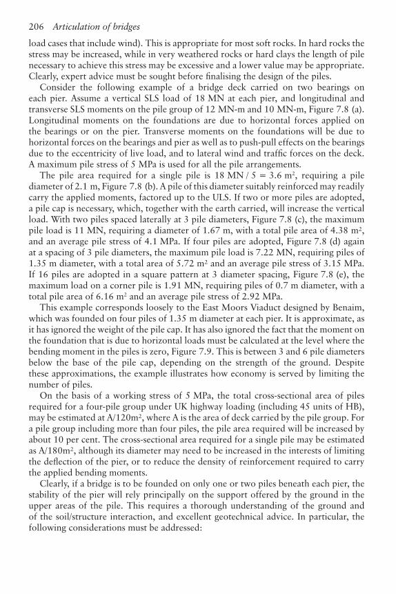
A maximum pile stress of 5 MPa is used for all the pile arrangements.
The pile area required for a single pile is 18 MN / 5 = 3.6 m2, requiring a pile
diameter of 2.1 m, Figure 7.8 (b). A pile of this diameter suitably reinforced may readily
carry the applied moments, factored up to the ULS. If two or more piles are adopted,
a pile cap is necessary, which, together with the earth carried, will increase the vertical
load. With two piles spaced laterally at 3 pile diameters, Figure 7.8 (c), the maximum
pile load is 11 MN, requiring a diameter of 1.67 m, with a total pile area of 4.38 m²,
and an average pile stress of 4.1 MPa. If four piles are adopted, Figure 7.8 (d) again
at a spacing of 3 pile diameters, the maximum pile load is 7.22 MN, requiring piles of
1.35 m diameter, with a total area of 5.72 m² and an average pile stress of 3.15 MPa.
If 16 piles are adopted in a square pattern at 3 diameter spacing, Figure 7.8 (e), the
maximum load on a corner pile is 1.91 MN, requiring piles of 0.7 m diameter, with a
total pile area of 6.16 m2 and an average pile stress of 2.92 MPa.
This example corresponds loosely to the East Moors Viaduct designed by Benaim,
which was founded on four piles of 1.35 m diameter at each pier. It is approximate, as
it has ignored the weight of the pile cap. It has also ignored the fact that the moment on
the foundation that is due to horizontal loads must be calculated at the level where the
bending moment in the piles is zero, Figure 7.9. This is between 3 and 6 pile diameters
below the base of the pile cap, depending on the strength of the ground. Despite
these approximations, the example illustrates how economy is served by limiting the
number of piles.
On the basis of a working stress of 5 MPa, the total cross-sectional area of piles
required for a four-pile group under UK highway loading (including 45 units of HB),
may be estimated at A/120m², where A is the area of deck carried by the pile group. For
a pile group including more than four piles, the pile area required will be increased by
about 10 per cent. The cross-sectional area required for a single pile may be estimated
as A/180m², although its diameter may need to be increased in the interests of limiting
the defl ection of the pier, or to reduce the density of reinforcement required to carry
the applied bending moments.
Clearly, if a bridge is to be founded on only one or two piles beneath each pier, the
stability of the pier will rely principally on the support offered by the ground in the
upper areas of the pile. This requires a thorough understanding of the ground and
of the soil/structure interaction, and excellent geotechnical advice. In particular, the
following considerations must be addressed:

Articulation of bridges 207
Figure 7.8 Bored pile options

208 Articulation of bridges
The pile may not be vertical; a tolerance on verticality of 1/75 is common. Conse-
quently, there will be a kink where the pier joins the pile, giving rise to horizontal
forces and additional bending moments.
The pile may not be precisely centred beneath the pier, giving rise to additional
bending moments at their point of junction; a positional tolerance of 75 mm is
typically used.
If the horizontal forces are repeated often, the pile could gradually loosen the
ground around it.
It may be necessary to carry out a preliminary pile test under horizontal forces, to
check the defl ection and rotation of the pile head at ground level.
The pile must be sound both structurally and geotechnically, and appropriate
testing regimes must be devised to ensure this.
The pile must be long enough so that it is effectively encastré in the ground, and
will not fail by rotating about its base.
7.8 The design of piers
Piers have a relatively simple engineering role, carrying the vertical loads from the
deck to the foundation, and resisting the various horizontal loads that can be applied
to the deck. However, they are very important visually. The simplicity of their function,
which makes them easy to understand by non-engineers, combined with their visual
importance, appears to exercise an irresistible fascination for some architects. The
number of simple, clean-lined bridge decks that have been ruined by neo-classical
•
•
•
•
•
•
Figure 7.9 Pile bending moment under the effect of a horizontal load

Articulation of bridges 209
columns or other such fantasies is legion. Also, for some reason, there is a fashion for
inclining piers, usually for no engineering reason.
Despite their simplicity, there is an engineering and functional logic that should act
as a starting point for the aesthetic design of piers.
Concrete is at its most economical when it is in direct compression, needing only
the bare minimum of reinforcement. When it is subjected to signifi cant bending,
heavier steel reinforcement is needed which increases its cost, and slows construction.
Consequently, the simplest and cheapest way to carry loads from the deck to the
foundations is to place a vertical column between the bearing and the foundation.
If the foundation then consists of a single pile beneath each column, the vertical
Figure 7.10 Types of pier

210 Articulation of bridges
Figure 7.11 Pier of STAR Viaduct (Photo: Benaim)
deck reaction is transmitted to the foundation stratum as economically as possible
without bending moments, Figure 7.10 (a). Eccentric live load moments, or dead load
torque due to plan curvature of the deck, are also carried to the foundations in direct
compression.
However, the pier is also subjected to lateral forces applied at the bearing, both
longitudinally and transversally. These create bending moments that are zero at the top
of the pier, and a maximum at the base. There is thus logic in widening the columns
near the base. This is shown clearly on the piers of the East Moors Viaduct, whose
articulation is described in 7.15.5 and Figure 7.26.
Piers consisting of one column per bearing are not always possible, or desirable.
When it is necessary to carry the deck on a pier consisting of only a single column,
the loads must be gathered in from the bearings by a crosshead. At one limit, this
crosshead may consist of a gradually fl ared column, Figure 7.10 (b), while at the other
limit it may consist of twin cantilevers, Figure 7.10 (c). Alternatively, the crosshead
may be incorporated into the deck as a diaphragm, Figure 7.10 (d) (the arrangement

Articulation of bridges 211
used on the Stansted Abbotts Bypass, shown in Figure 10.4) and Figure 7.10 (e). It
is also possible to share the bending moment between a deck diaphragm and a pier
crosshead, Figure 7.10 (f). Crossheads, whether they form part of the deck or the pier
are costly, and should only be used when strictly necessary.
When different types of bridge deck are compared, it is often forgotten that the deck
type may require expensive crossheads, and that this may have a very considerable
infl uence on the cost of the bridge as a whole.
If a box section deck carried by a fl ared column has a trapezoidal cross section, such
as in the STAR project, the bearings will be closer together, reducing the necessary
fl are. This fl are may be further reduced by placing the bearings in-board of the webs,
beneath a deck diaphragm, Figure 7.11, when a price will be paid in reinforcement in
the diaphragm.
Truss analogy may be used to determine the tension force that must be resisted across
the top of a fl ared pier, Figure 7.12 (a). This tensile force may be resisted by passive
Figure 7.12 Flared pier details

212 Articulation of bridges
reinforcement, or by prestressing. Whichever system is used, considerable care must
be taken in the detailing, to ensure that the bearing reactions are effectively enclosed
by the reinforcing bars or tendon anchorages, and frequently the pier head must be
widened for this reason. Also, the main mat of reinforcement may have to be lowered
to miss the bearing dowels, the bursting steel beneath the bearings, or drainage details
in the pier, affecting the appearance of the pier, Figure 7.12 (b). Clearly, the tensile
force at the top of the pier will be minimised if the fl are is made as deep as possible.
When mechanical bearings are used and the deck is pinned to one or more piers,
these special piers are subjected to additional forces due to acceleration/braking of
traffi c, longitudinal wind and to differential bearing friction (unequal coeffi cients of
friction either side of the points of fi xity). If the deck is fi xed to only one pier, it is
likely that this pier will need to be larger than typical piers, which creates a problem
both visually and functionally as it will require special formwork. If the deck is fi xed
on several piers as described in 7.9, it is usually the case that the standard pier may be
used, albeit with increased reinforcement.
In a long or complex viaduct, which may include a considerable variation of deck
height above ground level, of span lengths, of deck widths and include slip roads, it
is important design to create a family of piers that suits all situations with elegance,
economy of materials and with logical re-use of formwork.
The fi nish that should be given to the surface of piers depends on how closely they
may be seen by the public. For instance, it is not worth paying for an expensive ribbed
fi nish for piers that are isolated off shore. However, if the piers will be seen close to,
it is necessary to avoid large fl at concrete surfaces that are inevitably ugly. This may be
achieved by breaking up the surface with facets which change the way light refl ects and
hence the perceived shade of grey, or by applying a decorative fi nish. Examples are the
piers of the Byker Viaduct that were located in a public park, Figure 1.5, and of the
STAR urban viaduct, Figure 1.4.
7.9 The articulation of decks with mechanical bearings
7.9.1 General
Mechanical bearings are either pinned, guided or free sliding. One or more pinned
bearings hold the deck in place, with guided or free sliding bearings at all other
supports. This causes large concentrations of force on the pinned bearings.
Design strategies are aimed at reducing the cost and visual implications of this
concentration of fi xing force. Some of these strategies are examined in the following
sections.
One of the aims of the bridge designer should be to minimise the number of
maintenance-intensive mechanical devices, such as bearings and expansion joints that
are incorporated in a bridge deck. When they are necessary, the designer should choose
them to minimise the risk of malfunction and the cost of maintenance. Pinned bearings
are the simplest of the mechanical bearings, and should be used where possible; free
sliding bearings are simpler than guided bearings.

Articulation of bridges 213
7.9.2 Typical arrangement of mechanical bearings
Typically the deck is fi xed longitudinally on one abutment, on a single pier or on a
series of piers, and guided longitudinally on all other piers and abutments.
On a pier providing longitudinal fi xity, there would normally be one pinned bearing,
with the other bearings guided transversally, such that they share in carrying the
longitudinal loads but allow transverse expansion and contraction. On all other piers
or abutments, there is normally one bearing guided longitudinally, which carries the
transverse wind and traffi c loads, with the remainder being free sliding. However, if a
pier consists of a row of transversally fl exible columns, it may well be possible to place
longitudinally guided bearings on more than one column, distributing the transverse
load more evenly on columns and foundations. If the longitudinal movements are
large the bearing guides must be exactly parallel to each other.
7.9.3 Longitudinal fi xity at the abutment
Many continuous bridges in the UK are designed with the assumption that the deck
must be held rigidly in place longitudinally. As piers are more or less fl exible, this
requires the deck to be pinned to one abutment. However, this is the very worst place
to fi x a deck, and should be a last resort, for the following reasons:
When the deck expands or contracts, the sliding friction of all the bearings reacts
against the fi xed point. This bearing drag amounts to some 4–5 per cent of the
dead weight of the deck, which can be a very substantial force.
For most bridge decks, the vertical reaction on the abutment is much smaller than
on intermediate piers, particularly when the penultimate span is loaded. Bearings
that have to resist high horizontal loads combined with low vertical loads are non-
standard and are consequently expensive, may be slow to deliver, and may require
a special testing programme.
The abutment is usually subjected to horizontal forces from earth pressure; the
addition of longitudinal forces from the deck will usually result in a considerably
more expensive structure. The increase in cost is likely to be most signifi cant if the
abutment is carried by piles, where increasing the ratio of horizontal to vertical
forces is particularly onerous.
7.9.4 Longitudinal fi xity on a single pier
It is much better where possible to fi x the bridge deck on a pier, which has a greater
vertical reaction. Figure 7.13 (a) shows an example of a fi ve-span bridge carried on
four rows of columns. Bearing drag will be minimised if the fi xed pier is situated close
to the centre of the viaduct. However, it must be assumed that the bearings on either
side of the fi xed pier will have different friction coeffi cients. The differential friction
coeffi cient assumed should be greater as the number of bearings is smaller. Thus in a
bridge with only two spans, it should be assumed that the bearing friction coeffi cient
is 1 per cent on one abutment and 5 per cent on the other. When there are, say, ten or
more bearings either side of the point of fi xity, it would be unreasonable to expect that
all those on one side are very different to those on the other, and a differential friction
•
•
•

214 Articulation of bridges
Figure 7.13 Typical articulation with mechanical bearings
Articulation of bridges 215
coeffi cient of only 0.5 per cent would be reasonable. Codes of practice may impose
other ways of defi ning differential friction, for instance [5].
Clearly, once the deck is pinned to a pier which is to some extent fl exible, it is no
longer rigidly held in position. It is necessary to ensure that the movement under
longitudinal forces is not excessive, and can be accommodated by the expansion joints.
If this movement is too great, it is generally better to stiffen up the anchor pier, or to
anchor on a stiffer pier even if it is off centre, rather than to revert to fi xing the deck
on the abutment.
If the bridge is subjected to seismic forces, it may not be cost effective to design
the expansion joint to survive the deck movements caused by a severe earthquake.
However, the designer should ensure that vital parts of the deck, such as the prestress
anchors in the end face, would not be damaged by collision with the abutment.
External longitudinal forces applied to the deck may, as a fi rst approximation,
be assumed to be carried solely by the fi xed pier. However, in a long viaduct, the
contribution of all the other piers should be considered. As the fi xed pier defl ects
longitudinally the sliding bearings on other piers and abutments are displaced. Using
a conservative low friction coeffi cient of 1 per cent, the sliding bearings will carry a
signifi cant proportion of the longitudinal load, relieving the fi xed pier of stress and
making it more similar to typical piers. This applies also to decks that are pinned to
several piers, as described below.
Generally, for a deck of any length, a single fi xed pier will need to be thicker than
standard piers with sliding bearings.
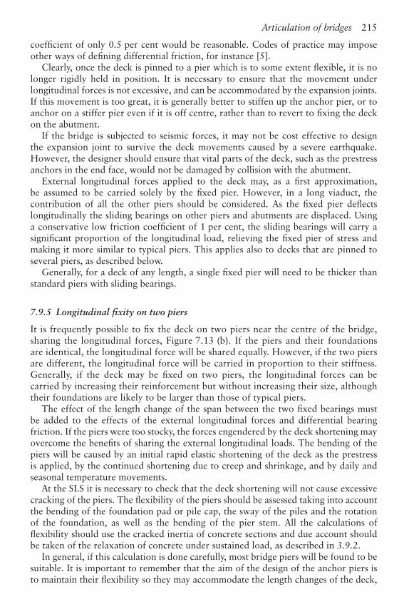
7.9.5 Longitudinal fi xity on two piers
It is frequently possible to fi x the deck on two piers near the centre of the bridge,
sharing the longitudinal forces, Figure 7.13 (b). If the piers and their foundations
are identical, the longitudinal force will be shared equally. However, if the two piers
are different, the longitudinal force will be carried in proportion to their stiffness.
Generally, if the deck may be fi xed on two piers, the longitudinal forces can be
carried by increasing their reinforcement but without increasing their size, although
their foundations are likely to be larger than those of typical piers.
The effect of the length change of the span between the two fi xed bearings must
be added to the effects of the external longitudinal forces and differential bearing
friction. If the piers were too stocky, the forces engendered by the deck shortening may
overcome the benefi ts of sharing the external longitudinal loads. The bending of the
piers will be caused by an initial rapid elastic shortening of the deck as the prestress
is applied, by the continued shortening due to creep and shrinkage, and by daily and
seasonal temperature movements.
At the SLS it is necessary to check that the deck shortening will not cause excessive
cracking of the piers. The fl exibility of the piers should be assessed taking into account
the bending of the foundation pad or pile cap, the sway of the piles and the rotation
of the foundation, as well as the bending of the pier stem. All the calculations of
fl exibility should use the cracked inertia of concrete sections and due account should
be taken of the relaxation of concrete under sustained load, as described in 3.9.2.
In general, if this calculation is done carefully, most bridge piers will be found to be
suitable. It is important to remember that the aim of the design of the anchor piers is
to maintain their fl exibility so they may accommodate the length changes of the deck,

216 Articulation of bridges
while retaining adequate strength to resist the longitudinal external forces applied to
the deck, and stiffness to control its longitudinal displacement. This is an excellent test
of the skill of a designer.
As the bending moments in the two anchor piers due to the deck shortening are of
opposite sign, at the SLS external longitudinal loads applied to the deck will increase
the bending on one of the two anchor piers and relieve it on the other.
At the ultimate limit state it must be remembered that the deck shortening consists
of imposed strains, not loads. Consequently if the anchor piers become over-stressed
by the deck shortening at the ULS, they would release the bending moments, either
by hinging at their base, or by rotation and sway of the foundation. For this to be a
safe assumption, the substructure must have a ductile mode of failure. The piers and
any piles must be adequately reinforced in shear. Piles must not be allowed to fail in
direct compression; either the pile shafts should be stronger than the ground, so over-
stressing would cause settlement rather than concrete failure, or the foundation should
be designed to withstand the ultimate vertical loads.
Under normal circumstances, foundation systems are adequately ductile. However,
if necessary, the ductility may be improved, for instance by designing the base of the
pier or the connection of the piles with the pile cap for plastic rotation. If the piers/
foundations are ductile, at the ULS both piers may be assumed to resist the external
longitudinal forces and the internal forces resulting from deck shortening may be
ignored.
7.9.6 Longitudinal fi xity on more than two piers
If the bridge deck rests on tall slender piers, it is quite possible to fi x the deck on
several of them. In fact, with design friction coeffi cients of the order of 5 per cent,
sliding bearings on piers near the null point may, in theory, never slide. Fixed bearings
are cheaper than sliding bearings and need less maintenance, so there is every incentive
to use them on as many piers as possible.
7.9.7 Null point
When a bridge deck is pinned to a single pier, it provides the fi xed point about which
the deck changes length. However, when the deck is pinned to two or more piers, the
position of the point of zero movement, or null point, needs to be calculated in order
to estimate the forces on the piers, the sliding movement at each of the bearings, and
the travel of the roadway expansion joints.
For a symmetrical deck with a symmetrical substructure pinned to two identical
piers, the null point for expansion and contraction will be mid-way between them,
Figure 7.14 (a). On the other hand, if for instance one pier is longer than the other, the
null point will be displaced towards the stiffer pier, Figure 7.14 (b). If the substructure
constituted an elastic system, as described in 7.10, the position of the null point could
be readily calculated, as the sums of the horizontal bearing forces either side of it must
be equal and opposite.
Unfortunately, a substructure that includes sliding bearings is not an elastic system.
The exact friction coeffi cient in each bearing is not known. Furthermore, sliding bearings
will not slide until the horizontal force overcomes the static friction. Thus as the deck

Articulation of bridges 217
changes in length, a pier will initially defl ect elastically. As the defl ection increases and
the shear force in the bearing builds up, the static friction will be overcome and the
bearing will slide, giving elasto-plastic load defl ection behaviour.
In calculating the null point, it is usually adequate to assume that the friction
coeffi cient of all bearings is some realistic mean fi gure, such as 2.5 per cent. The
position of the null point is then guessed. By calculating the movement of the bridge
deck at each pier position and comparing it with the fl exibility of the pier, it is then
possible to defi ne which bearings will remain locked, and which will slide. The shear
force in the piers with locked bearings can be calculated elastically, while the shear
force in piers where the bearings have slid is 2.5 per cent of the dead load reaction.
The total force each side of the null point may be calculated. If the position of the
null point used in this calculation was correct, the forces either side of it would be
equal and opposite. If the forces are not equal, the position of the null point may be
corrected, and the calculation repeated until equilibrium is achieved.
However, as the friction coeffi cient on each bearing is not known, there remains
some uncertainty about this calculation, which should be kept in mind when making
design decisions based on the position of the null point. In some situations, such as for
very long or highly unsymmetrical decks, it may be necessary to reduce the uncertainty
by repeating the calculation with different values of friction coeffi cient, or with some
Figure 7.14 Null point

218 Articulation of bridges
variability of coeffi cient between bearings. This would give a range of positions for
the null point, which would allow a more realistic design of the expansion joints, for
instance.
7.9.8 Curved decks
As a curved deck expands, both its length and its radius increase. Thus any point on
the deck has a component of movement along the bridge centre line, and a component
at right angles to it. Theoretically, all the guided sliding bearings should be aimed at
the point of fi xity of the deck, Figure 7.15 (a). This is not very convenient, as the
orientation of each bearing must be individually set. Moreover the lateral component
of the bearing movement that occurs at each pier may have aesthetic consequences,
and, at abutments, may compromise the operation of the expansion joints.
For most curved viaducts it is possible to align the bearing slide tracks with the local
axis of the deck, Figure 7.15 (b), and to constrain the deck to retain approximately its
nominal radius. The lateral forces on the bearings and the lateral bending moments
Figure 7.15 Orientation of bearings for curved decks

Articulation of bridges 219
on the deck caused by constraining it in this way are simply calculated using a space
frame, and in the great majority of cases are small compared with the other design
actions. In such a calculation, it is important to appreciate accurately the transverse
fl exibility of the piers, including their foundations, as very small lateral defl ections of
the piers will greatly reduce the transverse forces calculated on the assumption of rigid
supports. In some cases, the lateral forces may be found to be larger than desirable
on the abutments, which are usually rigid and cannot defl ect sideways. Omitting the
bearing guides on the penultimate pier, leaving the bearings as free sliding, gives the
deck extra freedom and generally reduces these forces to manageable proportions. Of
course, it is then necessary to ensure that the guided bearings on the second pier and
on the abutment are designed to carry the increased lateral wind loads.
7.9.9 Temporary fi xity during construction
When building a long viaduct span-by-span, it is necessary to ensure that the deck is
safely held in place at each stage of the construction. The extreme lower bound friction
coeffi cient of sliding bearings is so low, less than 0.5 per cent, that an unsecured bridge
could be displaced by accidental loads or even by exceptional winds.
In general, the completed viaduct would be held in place by a series of pinned
bearings near the centre, with all the other bearings being free sliding or longitudinally
guided. As construction proceeds from one end, the fi rst spans will be carried only by
sliding bearings. Some of these bearings need to be designed with locking bolts that
temporarily stop them sliding. Alternatively, the deck may be held in place during
construction by temporary locking devices that are independent of the bearings. The
load capacity of these temporary fi xings will be determined by the differential bearing
friction that may be applied at a particular stage of construction. If the temporary fi xed
point is moved forwards frequently as the deck erection progresses, the forces in the
temporary fi xing may be kept low.
When construction reaches the fi rst bearing that is pinned in the fi nal confi guration,
if no precautions were taken, it could be grossly overloaded by all the bearing
friction forces being applied from one side only. Consequently, it may be necessary to
temporarily free this bearing so that it can slide in response to a temporary point of
fi xity situated in the completed portion of the deck. Once suffi cient spans have been
erected beyond the permanent fi xed bearing to bring the differential friction loads
within its design capacity, it may be permanently locked. A simple example of this
procedure is given in Figure 7.16.
It is very important to consider these aspects of temporary fi xity and temporary
release of bearings suffi ciently early in the design. Bearings require long lead times for
ordering, and if these considerations are approached only at the last minute, they can
lead to expensive modifi cations to bearings that have already been fabricated.
7.9.10 Use of shock absorbers
High capacity shock absorbers that allow a slow extension of the piston but lock up
under rapid movements, can be fi xed between a bridge deck and a fi xed point such
as a pier or an abutment, or between successive sections of a bridge deck in a long
viaduct. Thus they allow the bridge to expand and contract freely under the effects of

220 Articulation of bridges
creep, shrinkage and temperature change, but lock up under the effects of acceleration/
braking or seismic forces.
An example would be a railway bridge on very tall piers. The deck may well be
fi xed onto some of the piers, with sliding bearings on the others and on the abutments.
Thus effects of differential friction would be shared between several piers, as described
above. However, under the effect of a train accelerating on one track and braking on
the other, the columns providing deck fi xity may be too fl exible, allowing excessive
longitudinal movements. If shock absorbers were to be attached between the bridge
deck and one of the abutments (or both abutments), these sudden forces would be
carried rigidly by the abutment, Figure 7.17 (a).
Figure 7.16 Temporary fi xity of deck built span-by-span

Articulation of bridges 221
Another example is a very long railway viaduct, split up into expansion lengths.
If the piers were fl exible, they could be all pinned to the deck. The acceleration and
braking forces are applied by trains of fi nite length. If the whole viaduct is considerably
longer than one train length for a single track railway, or two train lengths for twin
tracks, such forces may be distributed to all the piers of the viaduct by placing shock
absorbers between each of the expansion lengths. Thus for all slow movements the
expansion lengths behave as separate entities, while for sudden loads the whole viaduct
acts as one, Figure 7.17 (b).
An alternative solution to the above example would be for each expansion length to
have at its centre an anchor pier (or piers) that was stiffer than the others, and strong
enough to carry the acceleration/braking forces on that expansion length. This would
probably have a higher fi rst cost, but would not have the maintenance liability of the
locking devices, Figure 7.17 (c).
Figure 7.17 Use of shock absorbers

222 Articulation of bridges
7.10 Deck on laminated rubber bearings
The use of laminated rubber bearings provides the designer with a very useful additional
tool for controlling the articulation of his bridge. In particular, the shear stiffness of
the bearings can be adjusted so that the distribution of longitudinal forces between the
piers is under his control.
The plan area of a bearing is determined by the design load. The capacity of a
bearing to accept rotations depends on its length in the direction of the rotation, on
the total thickness of rubber and on the thickness of the individual layers; the thicker
the layers, the more rotationally fl exible is the bearing. The shear stiffness of a bearing
depends on its plan area and on the total thickness of rubber.
When designing the articulation for a long viaduct the engineer would normally
start by defi ning bearings that had the minimum thickness of elastomer required to
accept the design rotations. The central piers of the viaduct would be equipped with
such bearings that maximise shear stiffness. Thus the piers that are the least loaded by
length changes of the deck are provided with the stiffest bearings to attract a greater
proportion of the external longitudinal applied loads. For piers further from the centre
of the viaduct that are more affected by the length changes of the deck, the bearings
would be made progressively thicker, the aim being to equalise as far as possible the
longitudinal loads carried by each pier, Figure 7.18. In this calculation, the fl exibility
of the piers must be added to that of the bearing; the pier and bearing constitute
a single elastic system. Clearly, the choice of the shear stiffness of the bearings is a
cyclical calculation. The abutments, which cannot defl ect, must be equipped with
thicker bearings, with bearings that can be reset, or with mechanical sliding bearings.
A substructure equipped with rubber bearings is an elastic system, and the null
point may be calculated accurately, as can the share of longitudinal load carried by
each pier. For a substructure where the piers vary in height and thus in stiffness, the
bearing thickness can be tuned to control the distribution of longitudinal force on the
piers. For example, if one pier were excessively stiff due to it being founded on high
ground, it would tend to pick up a greater share of longitudinal loads. However, the
rubber bearing on that pier may be made thicker and hence more fl exible in shear, to
bring the overall fl exibility of the pier into line with the others.
A deck carried on rubber bearings does not have any ‘fi xed point’. However, it is a
very safe, highly redundant system, as the longitudinal stability of the deck does not
depend on any one pier.
Laminated rubber bearings need no maintenance, although they should be inspected
regularly, and provision must be made to replace them, usually after a life of several
decades.
Figure 7.18 Typical example of the use of rubber bearings

Articulation of bridges 223
Generally it is not necessary to organise temporary fi xity for decks carried by rubber
bearings during span-by-span construction, as there is always a degree of restraint
of the bridge deck. However, the sequence of application of shear deformation to
the bearings during construction should be thought through, as some bearings may
become temporarily or permanently over-stressed in shear. Rubber bearings can in
general accept a substantial degree of temporary over-stressing, in shear, rotation and
direct load. However, the manufacturers should be consulted.
A typical example of this form of articulation is given by the GSZ project in China
which is described in 7.15.2 below.
7.11 Piers built into the deck
The lowest maintenance solution of all is to eliminate the bearings altogether, and
build the pier into the deck. This creates a portal structure, and live loads on the deck
generate bending moments and shears in the piers, which are also transmitted to the
foundations. The bending moments in the deck are substantially changed, with an
increase in hogging moments over the supports, a decrease in sagging moments at
mid-span, together with a decrease in the variation of live load bending moments.
These changes to deck moments generally signifi cantly reduce the amount of prestress
required, particularly if the deck has variable depth, allowing the greater support
hogging moments to be carried economically by the increased depth. However, this
cost saving in the deck may be at the expense of increased cost in the piers and more
particularly in the foundations.
The feasibility of fi xing the deck to the piers in this way depends principally
on whether the structure can cope economically with the forces generated by the
shortening of the bridge deck. If the deck is long, and not very high above the ground,
it may only be possible to build in the two central piers, with those further from the
centre of the bridge requiring pinned or sliding bearings to accommodate the length
changes. If the deck is high above the ground, more piers may be built in. However, for
most bridges, particularly those that cross valleys, the end piers are likely to be shorter
than those near the centre, which of course makes them less able to accommodate the
deck shortening.
Once the building in of the piers is accepted as a design objective, simplifying the
bridge mechanically and reducing fi rst cost and maintenance, it may be used far more
widely than is currently the case. For instance, the decks of most motorway over-
bridges could be built into their piers, increasing at the same time the resistance of
piers to vehicle impact.
The limit on this form of construction is usually the degree of cracking of the pier
stem under service conditions that is considered acceptable. More research is required
on the extent of the relaxation of reinforced concrete piers subjected to permanent
shortening due to creep and shrinkage of the deck, and on the extent and harmfulness
of the cracking due to these effects when added to the cyclic temperature movements
of the deck.
7.12 Split piers
When a pier is built into the deck, its bending stiffness modifi es the bending moments
in the deck, with economic benefi ts. On the other hand its shear stiffness is a

224 Articulation of bridges
disadvantage, as it resists the length changes of the deck. If the pier is divided into
two fl exible leaves, the bending stiffness can be retained, while the shear stiffness is
greatly diminished. This may best be understood by considering a pier consisting of
an ‘I’ beam, Figure 7.19. The bending strength of the beam is provided by the two
fl anges, while the shear strength is provided by the web. If the web is removed, the
bending strength remains, but the shear strength is destroyed. Thus the benefi ts to
the deck bending moments are retained, while the length changes of the deck are less
restrained, allowing a longer length of the deck to be built-in in this way.
The spacing of the two leaves has a marked infl uence on the design. Live load on
one span will cause uplift on the remote column of the pair. If the leaves are close
together, the uplift will overcome the dead load reaction on the remote column and
put it into tension. The degree of moment fi xity of the deck gradually reduces as
the columns are brought closer together. This is due to the shortening of the near
column and the extension of the remote column, which allows the node between
Figure 7.19 Development of twin leaf piers
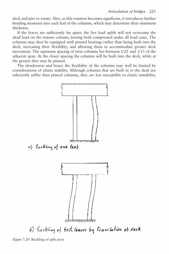
Articulation of bridges 225
deck and pier to rotate. Also, as this rotation becomes signifi cant, it introduces further
bending moments into each leaf of the columns, which may determine their minimum
thickness.
If the leaves are suffi ciently far apart, the live load uplift will not overcome the
dead load on the remote column, leaving both compressed under all load cases. The
columns may then be equipped with pinned bearings rather than being built into the
deck, increasing their fl exibility, and allowing them to accommodate greater deck
movement. The optimum spacing of twin columns lies between 1/25 and 1/13 of the
adjacent span. At the closer spacing the columns will be built into the deck, while at
the greater they may be pinned.
The slenderness and hence the fl exibility of the columns may well be limited by
considerations of elastic stability. Although columns that are built in to the deck are
inherently stiffer than pinned columns, they are less susceptible to elastic instability,
Figure 7.20 Buckling of split piers

226 Articulation of bridges
and thus may be made thinner, recovering fl exibility. The essence of the design of such
split piers is to fi nd the correct compromise between the fl exibility and the elastic
stability of the leaves. In considering stability when the deck is in service, it is relevant
that usually only one leaf of a pair is highly compressed under any load case, with the
less compressed leaf providing stability by resisting translation of the deck. Also the
columns are usually only highly stressed in compression under transient loading, when
the higher, short-term Young’s modulus is used to check buckling.
As well as considering the buckling of the individual leaves of the split piers, it is also
necessary to check the buckling mode where the whole deck translates longitudinally,
Figure 7.20. This will be controlled by the shortest piers, and may also be inhibited if
the deck is curved in plan.
A good example of a deck supported on split piers is the valley section of the Byker
Viaduct, Figure 1.5, described in 7.15.4.
If the piers are very short, it may be necessary to further subdivide them in order to
reduce the shear stiffness enough, while maintaining adequate moment capacity. This
is demonstrated on the River Nene Bridge, described in 11.6 and in Figures 11.16
and 11.17. It was necessary to make this bridge deck as slender as possible so that it
would fi t between an imposed highway alignment and river clearance requirements.
Thus a 700 mm thick prestressed concrete voided slab was allowed to span 39.9 m
by providing local haunches that were built into the piers. The piers, which were
divided into fi ve 200 mm thick precast concrete planks, provided a very high degree
of moment fi xity to the deck combined with very low shear stiffness.
7.13 Integral bridges
One of the aims of a designer of concrete bridges should be to reduce maintenance
by minimising the number and sophistication of mechanical engineering devices
required for its operation. Thus, wherever possible, piers should be built into the
deck. Where this is not possible, the next best option is to adopt concrete hinges
(codes allowing), then rubber bearings, then fi xed mechanical bearings, and last of
all, sliding bearings.
However, the greatest single item of maintenance expenditure on highway bridges is
the expansion joint. Not only do such joints need regular repair and renewal, but they
also allow salt-laden water to attack and corrode the substructure. Most attempts at
creating waterproof joints fail after a number of years of service. Expansion joints also
need to be inspected from beneath, which greatly increases the cost and complexity
of abutments.
Integral bridges take the philosophy of mechanical simplicity to its logical conclusion
by either pinning the deck to the abutment or building it in. This eliminates the expansion
joint and greatly simplifi es the abutment structure that becomes more like a pier.
The consequence of this type of design is that the abutment either rocks or slides
back and forth as the bridge expands and contracts, causing settlement of the backfi ll
behind the abutment, and disrupting the road surface. This is overcome either by
regular maintenance of the road surface, or by bridging the disrupted area with a short
transition slab. The slab is attached to the abutment, and so follows its movement,
sliding on the substrate. Consequently, a fl exible mastic type joint is required in the
blacktop at the end of the transition slab. Some authorities adopt transition slabs,
while others prefer to maintain the road immediately behind the abutment [6, 7, 8].

Articulation of bridges 227
A very economical form of abutment is achieved by separating the functions of
soil retention and support of the deck. The soil is retained by a reinforced earth wall,
while the deck is carried on piles that are allowed to rock within the fi ll. The piles
may be concrete or steel, and may be encased in pipes to give them the freedom to
rock. It needs to be demonstrated that steel piles would be adequately protected from
corrosion; they would appear to be more at risk than similar piles driven into the
embankment.
Integral bridges have been designed in the USA with lengths up to 352 m according
to [5]. However, current UK guidelines in BA42/96 suggest a very conservative limit
of 60 m. The same standard also suggests limiting the skew to 30°.
Building in piers and abutments and eliminating bearings and expansion joints
should be a major aim of the bridge designer.
7.14 Continuity versus statical determinacy
7.14.1 General
The designer of small to medium span bridges often has the choice between decks
that are continuous and those that are statically determinate. The choice is not
straightforward, and depends on the consideration of many factors, which may be
grouped under the headings:
economy of materials;
safety;
method of construction;
maintenance and use.
7.14.2 Economy of materials
Theoretically, the weight of reinforcement required for a reinforced concrete beam
is proportional to the area beneath the bending moment diagram. Figure 7.21 (a)
shows a simply supported beam of span l subjected to a uniformly distributed load.
The maximum bending moment is 0.125 wl2, where w is the unit load. The area
beneath the diagram is 0.0833 wl3. Figure 7.21 (b) shows a built-in beam of identical
span hinged at mid-span, subject to the same load. Although the maximum bending
moment is also 0.125 wl2, the area beneath the diagram is 0.0417 wl3, half that of
the simply supported beam. Figure 7.21 (c) shows a built-in beam without the mid-
span hinge, where the bending moment at the supports is 0.0833 wl2 and at mid-
span is 0.0417 wl2, and the area beneath the diagram is 0.0278 wl3, one-third that
of the statically determinate span. This simple demonstration shows that hogging
moments are cheaper to reinforce than sagging moments, because the bars can
be shorter, and that a continuous beam should be much more economical than a
statically determinate beam.
However, for bridge decks the theoretical advantage of the continuous beam is
eroded in several ways. Live loading may be applied to individual spans of a continuous
beam, giving rise to an envelope of moments that has a much larger requirement
in reinforcement, Figure 7.21 (d). Furthermore, a continuous bridge deck must be
designed for additional bending moments due to differential settlement of foundations,
••••

228 Articulation of bridges
and to temperature gradients through the deck, both of which are absent in a simply
supported deck. On the other hand, statically determinate beams show some small
savings in concrete and simplifi cations in construction due to the lack of anchorage
blisters within the span and to the use of thinner webs near the supports, as the prestress
may be effectively tuned to counteract shear force.
In practice, for prestressed concrete decks below about 45 m span, continuity saves
about 20 per cent of the prestress. Although this saving is substantial, for these short-
span bridges the most appropriate method of construction will generally dictate the
form of bridge. For longer spans, where self weight predominates, the savings offered
by continuity are greater; it is most unusual to see statically determinate beams with
spans exceeding 45 m.
Figure 7.21 Areas beneath bending moment diagrams

Articulation of bridges 229
7.14.3 Safety
Indeterminate structures have more reserves of strength than statically determinate
structures. For instance, if a mid-span section of a continuous bridge deck lost some of
its reinforcement due to corrosion, bending moments may be redistributed to supports,
giving warning defl ections and delaying collapse. Also, in the event of extreme
accidental damage, such as the collision of a train with the supports of an overbridge,
a continuous structure may avoid complete collapse and reduce the severity of the
accident. On the other hand, if the accident is so severe that it completely removes
a pier, a statically determinate deck would limit the damage to the bridge to just two
spans, where a continuous bridge is likely to be more extensively damaged.
In severely seismic regions, continuity reduces the risk of decks being shaken off
their bearings. However similar benefi ts can be obtained by linking determinate spans
together as described in 7.15.2.
Continuous decks are more vulnerable to damage due to unforeseen or under-
estimated effects, such as settlement of foundations, temperature gradients or heat of
hydration effects if cast in-situ.
In general, although continuity does give a greater resilience to a structure, this is
less important for a bridge than for a building. Bridges are more highly analysed, are
more easily and regularly inspected, and are subjected to a more determinate variety
of risks than buildings.
7.14.4 Method of construction
Some forms of construction lend themselves more naturally to determinate or
indeterminate decks. Decks formed of precast, prestressed beams are naturally simply
supported, and measures taken to make them continuous are time-consuming and
generally uneconomical.
In general, very long viaducts with regular spans consisting of precast elements,
erected by highly mechanised gantries, where speed of construction is essential
for economy, are designed as statically determinate. The time needed to create
continuity between decks usually rules out this option. For instance, the fi rst scheme
designed by Benaim for the 17 km long GSZ Pearl River Delta Viaducts (15.9.2)
used prefabricated decks each consisting of a 32.5 m long, 15.4 m wide box girder
weighing 620 tons. These decks were due to be placed by gantries at the rate of up to
three per day per gantry. For such a rate of construction, creating continuity would
have caused unacceptable delays, more than doubling the duration of the erection
programme.
On the other hand, when decks are cast in-situ span-by-span, either on gantries
or on staging, it is more diffi cult to make them statically determinate than to make
them continuous. Consequently such a form of construction leads more naturally to
continuous beams. Similarly, decks built in balanced cantilever, both precast and cast
in-situ, are usually made continuous; mid-span hinges and drop in spans are no longer
considered economical or desirable. Bridges built using the method of incremental
launching are naturally continuous, although expansion joints may be introduced if
necessary, at additional cost due to the disruption to the fl ow of construction.

230 Articulation of bridges
7.14.5 Maintenance and use
There are many poor existing examples of statically determinate prestressed concrete
highway bridges. Precast beams were frequently built without negative pre-cambers,
and as a result hog up under permanent loads and give a poor ride, which sometimes
excites the resonant frequency of car suspension. Expansion joints at each pier require
excessive maintenance and further reduce the quality of the ride, as well as providing
paths for aggressive run-off water to attack deck ends and piers. Such bridges have
created a prejudice against statically determinate decks.
However, these defects were the result of poor design, and are not inherent in
the lack of continuity. For instance, the GSZ viaducts (7.15.2 and 10.3.8) consist of
32.5 m span statically determinate precast, post-tensioned Tee beams built with the
correct pre-camber, and linked through their top slabs in expansion lengths of nine
spans. Thus expansion joints only occur at some 300 m intervals. The ride and the
maintenance requirements are as good as on the equivalent continuous deck.
A similar solution was adopted on the many kilometres of the Bangkok Second
Stage Expressway, where statically determinate precast segmental box section decks,
erected on gantries, were linked through their top slabs in groups of four spans.
Railway viaducts have a different logic. For ballasted track it is advantageous to
limit the bridge deck expansion lengths to about 100 m to avoid the need for expensive
and maintenance-intensive rail expansion joints. Also, the deck expansion joints
required for rail bridges are very simple, and as the decks are not salted, water run-
off onto the substructure is not as corrosive as on highway bridges. Thus for ballasted
track, statically determinate spans are frequently preferred. However, for city centre
locations where deck slenderness is important and where span lengths may be variable,
continuous decks ballasted or not, are frequently used, with rail expansion joints every
400 m or less.
If paved track is used, deck end rotations and deck length changes are transmitted
directly to the rails, as are any vertical defl ections of the bearings or pier crossheads.
Short statically determinate spans may still be used, but it is necessary to check that
the rails and their fasteners can accommodate these deck end movements, and that the
relevant railway authority accepts this solution. Otherwise continuous decks should
be adopted.
7.14.6 Conclusion
For spans below about 45 m, there is no overwhelming economic, safety or maintenance
case for either continuous or statically determinate decks. By and large, continuous
beams are more suited to balanced cantilever erection and to all forms of cast-in-situ
construction, while their decks and piers may be more slender and elegant. Statically
determinate decks are well suited to long precast concrete viaducts with regular spans,
where speed of erection is of the essence, and to ballasted railway viaducts. For spans
above about 45 m, statically determinate spans are not competitive. Both continuous
and statically determinate decks have their place, and it is up to the designer to weigh
the options.

Articulation of bridges 231
7.15 Examples of bridge articulation
7.15.1 General
The descriptions of the preceding sections of this chapter may best be illustrated by
giving some typical examples of the articulation of bridges designed by the author.
In accordance with the general theme of this book, these examples are not given as
models to be followed, or as examples of ‘best practice’. If the author were to design
these bridges again he may do them differently. These examples just show how the
principles described above work out in practice.
7.15.2 GSZ Pearl River Delta Viaducts
The viaducts extended for 17 km across the Pearl River Delta in South China, and carry
the dual four lane carriageways of the Guangzhou–Shenzhen–Zuhai Superhighway on
two adjacent decks, each 15.4 m wide, with spans of 32.5 m. Each deck consisted of
fi ve precast, post-tensioned beams, joined by a cast-in-situ top slab (10.3.8). Groups
of nine statically determinate spans were linked by their top slabs into 290 m long
expansion units, Figure 10.18.
The ground was soft in the upper layers, with sedimentary rocks at a variable depth
below, generally between 10 m and 20 m. The foundations were made with bored
piles that penetrated 2.5 diameters into the hard stratum. This rock socket allowed the
piles to rely for their working load strength on side friction in the rock, rather than on
end bearing. With such a short penetration into rock, the piles were dependent on the
support of the ground for their stability.
Each expansion unit was stabilised by two central anchor piers. The anchor piers
were founded on a group of four piles of 1.35 m diameter while the six intermediate
piers of each expansion unit were founded on pairs of 1.5 m diameter piles, one per
column. Each deck beam rested on a laminated rubber bearing 400 mm square. The
bearings consisted of 12 mm thick rubber leaves alternating with 3 mm steel plates,
with 6 mm of rubber on the top and bottom surfaces. At the anchor piers the bearings
had fi ve internal rubber layers, which was the minimum necessary to cope with the
deck and pier head rotations. The joint piers, which could not defl ect with the length
changes of the deck, had up to 11 rubber layers. At the intermediate piers the bearing
thickness depended on the distance from the null point and on the fl exibility of the
pier/foundation. These piers were stabilised against cantilever mode buckling by their
elastic connection to the deck. As it was considered that the thicker bearings on the
joint piers did not give them adequate stability, they were founded on a group of four
1.35 m piles.
7.15.3 STAR Viaduct in Kuala Lumpur
This viaduct extends for 6 km through the centre of Kuala Lumpur, and carries the
twin tracks of the STAR Light Rapid Transit System, Figures 7.22 and 7.11 (15.5.11). The rails are carried on concrete plinths. It was built by Taylor Woodrow International
to a preliminary and detailed design by Benaim [7]. The continuous precast segmental
box girder deck was divided into expansion lengths of approximately 300 m, which
is close to the limit for which a simple scarf expansion joint may be adopted for the

232 Articulation of bridges
rails. The bridge had a sinuous alignment, with horizontal curves with radii as tight
as 130 m. The spans of the deck varied considerably due to the constraints of the
city centre location. Typically, interior spans were 35.1 m or 51.3 m. End spans were
22.95 m when associated with shorter interior spans and 33.75 m adjacent to the
longer spans. The bridge deck also carried the stations, when the spans were normally
40.5 m. For the 35.1 m spans, the deck had a constant depth of 2.2 m, while for the
51.3 m spans it was haunched to 2.7 m at supports. For the spans carrying the stations,
the depth was constant at 2.7 m.
The soil consisted generally of 15–25 m of soft materials overlying marl type soft
rocks for the greater part of the length. On some sections the bedrock consisted of
heavily eroded limestone. Each pier for the typical 35.1 m spans was founded on
a single bored pile of 1.8 m diameter, generally over 30 m long, founded in a rock
socket, Figure 7.23. The piles were designed with a factor of safety of 1.5 on friction
alone, disregarding end bearing, and with a factor of safety of 2 on ultimate shaft
friction and 3 on ultimate end bearing.
As the tightly curved railway alignment applied centrifugal forces to the foundations,
as well as moments due to transverse eccentricity of load when only one track was
loaded, full-scale trial piles were subjected to horizontal load tests, using a second
reaction pile. The load was cycled to check that the horizontal stiffness of the ground
did not deteriorate unacceptably with repeated loading.
One of the principal advantages of using a single-pile foundation for this town
centre location was that no pile cap was necessary, only a junction section hardly larger
than the pile itself, minimising the displacement of services and traffi c disruption.
However, in any context it is an economical option as long as the ground conditions
are suitable.
Figure 7.22 STAR Viaduct (Photo: Benaim)

Articulation of bridges 233
Under typical 52.5 m spans, the foundation consisted of two 1.5 m diameter piles,
arranged laterally and inclined to reduce the bending moments due to centrifugal
forces. This arrangement of piles left the pier fl exible in the longitudinal direction.
The spans carrying the stations were founded on pile caps supported by four piles.
Each expansion length was anchored on a group of central piers equipped with
fi xed pot bearings. Joint piers and intermediate piers were equipped with one guided
and one free-sliding pot bearing. The number of fi xed piers was maximised, taking
advantage of the fl exibility of the single-pile foundation. As the two bearings on each
fi xed pier were less than 3 m apart and as the deck was made of precast segments,
Figure 7.23 STAR Viaduct: typical cross section

234 Articulation of bridges
the transverse length changes between bearings were insignifi cant, and two pinned
bearings were used on each pier.
7.15.4 The Byker Viaduct, Valley section
The Byker Viaduct was designed by the author when at Arup, with the architectural
assistance of Humphrey Wood of Renton Howard Wood Levine. This section of the
viaduct was approximately 380 m long and was aligned on a 390 m radius curve,
Figure 1.5. It carried the twin railway tracks of the Tyne & Wear Metro on paved track
and consisted of three main spans of 69 m, fl anked by side spans of 52.8 m, and at one
end two short approach spans. The main spans crossed a deep valley, with the tallest
piers being some 30 m high to deck level [8].
The four main piers which carried the three longest spans and their side spans
consisted of two leaves built into the deck and to the pile caps, Figure 7.24. Each leaf
was ‘I’ shaped with 1.1 m thick ends and a 400 mm thick web. The two leaves are
spaced at 2.9 m centres, Figure 7.25. The end thickenings fl are outwards near the base
of the columns to increase stability under the centrifugal forces, and to allow the web
to be cut away. These piers are stiff for moments and fl exible for shear, absorbing the
length changes of the deck. They also provide a stable base for free cantilever erection,
obviating the need for temporary supports. The buckling stability of the longest piers
was enhanced by their attachment to shorter piers, and by the plan curvature of
the deck.
Such slender columns are particularly vulnerable to buckling during construction,
as it is possible for the incomplete deck to sway longitudinally. The stiffness of
Figure 7.24 Byker Viaduct: valley piers (Photo: Robert Benaim)

Articulation of bridges 235
Figure 7.25 Byker Viaduct (Based on drawing by Arup)
the columns was enhanced during construction by stressing a temporary concrete
diaphragm between them. This was suffi ciently long (vertically) to provide rotational
fi xity to the columns at their mid-height, halving their effective length, Figure 15.31.
The abutment and the short piers carrying the end spans were equipped with sliding
bearings.
Each main pier is founded on four bored piles of 2.1 m diameter. As the foundations
are in a coal-mining area which may be subject to settlement, the piles were not built
into the pile caps, and were provided with the facility to be re-levelled if necessary.
7.15.5 East Moors Viaduct
The viaduct was 915 m long with expansion joints only at the ends. The prestressed
concrete single-cell box section deck was on an ‘S’ shaped alignment, and had typical
spans of 52.5 m. At each pier the deck was carried by two pot bearings that each
rested directly on a reinforced concrete column, Figure 7.26. The deck was fi xed
onto the two central piers, each equipped with one pinned and one transversally
guided bearing. These fi xed piers were the same size as the other piers, but were
more highly reinforced. All other piers had a guided sliding bearing on one column,
with the slides orientated along the deck axis, and a free sliding bearing on the other
column. The two columns of each pier were linked by a cross-beam that shared the
lateral load between them, and fl ared transversally at their base to resist the lateral
and longitudinal moments. Each pier was carried by four 1.35 m diameter piles
beneath a pile cap. The abutments were carried by one row of vertical and one row
of raking 1.35 m piles.

236 Articulation of bridges
7.15.6 Project for the Dong Po South Bridge
The bridge was designed to cross a major affl uent of the Pearl River in Guangdong
Province, South China, Figures 9.32 to 9.36 (9.5.7), and references [9] and [10] to
Chapter 18. It comprised two adjacent double deck bridges with trussed concrete
webs, each accommodating four motorway lanes on its top deck, and three lanes inside
the box structure. The three main spans were each 160 m, with end spans of 110 m.
The shipping clearance beneath the bridge was 20 m. Each intermediate pier consisted
of two rows of two columns built into the deck, and spaced at 12 m along the bridge
axis. These twin piers would provide a stable base for balanced cantilever erection
and provide moment fi xity to the deck, while the columns were suffi ciently tall and
fl exible to accept the length changes of the deck. At each end, the deck rested on a
single fl exible column, also built into the deck. Thus the 700 m long bridge had no
bearings. As the bridge was prolonged at each end by approach viaducts, there were no
abutments. Roadway expansion joints were provided at each end of the bridge, where
it connected to the approach viaducts.
7.15.7 Project for the Ah Kai Sha Bridge
This double deck, cable-stayed bridge was designed to cross the Pearl River in South
China with a shipping clearance of 34 m. It was 42 m wide and carried 16 lanes of traffi c
on two levels. It had a main span of 360 m and side spans of 172 m, Figures 18.18 to
18.21 (18.4.11) and references [9] and [10] to Chapter 18.
The two 114 m high reinforced concrete towers of each pylon were split longitudinally
into two leaves that were built into the deck. Each leaf was dumb-bell shaped, and was
Figure 7.26 East Moors Viaduct (Photo: Benaim)

Articulation of bridges 237
2.5 m thick and 7 m wide at the base. The leaves were spaced at 7.5 m centres at the
base, reducing to 5 m at a point beneath the cable stay anchorages. Above this point
the leaves were joined together to form a single box section. This arrangement gave
the pylons the strength necessary to resist lateral and longitudinal forces on the deck
while maintaining the fl exibility necessary to accommodate the length changes. It also
provided a stable base for the erection of the deck in balanced cantilever. The end
supports consisted of fl exible concrete columns, built into the deck. Thus, the bridge
had no bearings, minimising maintenance.