Article 5.10.8.4.2b Page 1 of 7 10/2017 - Idaho ...apps.itd.idaho.gov/apps/bridge/manual/05...
7
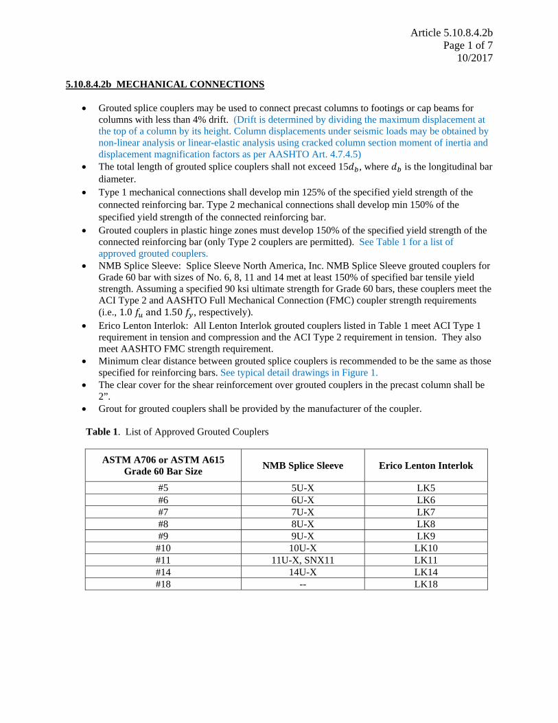
Article 5.10.8.4.2b Page 1 of 7 10/2017 5.10.8.4.2b MECHANICAL CONNECTIONS Grouted splice couplers may be used to connect precast columns to footings or cap beams for columns with less than 4% drift. (Drift is determined by dividing the maximum displacement at the top of a column by its height. Column displacements under seismic loads may be obtained by non-linear analysis or linear-elastic analysis using cracked column section moment of inertia and displacement magnification factors as per AASHTO Art. 4.7.4.5) The total length of grouted splice couplers shall not exceed 15 , where is the longitudinal bar diameter. Type 1 mechanical connections shall develop min 125% of the specified yield strength of the connected reinforcing bar. Type 2 mechanical connections shall develop min 150% of the specified yield strength of the connected reinforcing bar. Grouted couplers in plastic hinge zones must develop 150% of the specified yield strength of the connected reinforcing bar (only Type 2 couplers are permitted). See Table 1 for a list of approved grouted couplers. NMB Splice Sleeve: Splice Sleeve North America, Inc. NMB Splice Sleeve grouted couplers for Grade 60 bar with sizes of No. 6, 8, 11 and 14 met at least 150% of specified bar tensile yield strength. Assuming a specified 90 ksi ultimate strength for Grade 60 bars, these couplers meet the ACI Type 2 and AASHTO Full Mechanical Connection (FMC) coupler strength requirements (i.e., 1.0 ௨ and 1.50 ௬ , respectively). Erico Lenton Interlok: All Lenton Interlok grouted couplers listed in Table 1 meet ACI Type 1 requirement in tension and compression and the ACI Type 2 requirement in tension. They also meet AASHTO FMC strength requirement. Minimum clear distance between grouted splice couplers is recommended to be the same as those specified for reinforcing bars. See typical detail drawings in Figure 1. The clear cover for the shear reinforcement over grouted couplers in the precast column shall be 2”. Grout for grouted couplers shall be provided by the manufacturer of the coupler. Table 1. List of Approved Grouted Couplers ASTM A706 or ASTM A615 Grade 60 Bar Size NMB Splice Sleeve Erico Lenton Interlok #5 5U-X LK5 #6 6U-X LK6 #7 7U-X LK7 #8 8U-X LK8 #9 9U-X LK9 #10 10U-X LK10 #11 11U-X, SNX11 LK11 #14 14U-X LK14 #18 -- LK18
Transcript of Article 5.10.8.4.2b Page 1 of 7 10/2017 - Idaho ...apps.itd.idaho.gov/apps/bridge/manual/05...
Article 5.10.8.4.2b Page 1 of 7
10/2017
5.10.8.4.2b MECHANICAL CONNECTIONS
Grouted splice couplers may be used to connect precast columns to footings or cap beams for columns with less than 4% drift. (Drift is determined by dividing the maximum displacement at the top of a column by its height. Column displacements under seismic loads may be obtained by non-linear analysis or linear-elastic analysis using cracked column section moment of inertia and displacement magnification factors as per AASHTO Art. 4.7.4.5)
The total length of grouted splice couplers shall not exceed 15 , where is the longitudinal bar diameter.
Type 1 mechanical connections shall develop min 125% of the specified yield strength of the connected reinforcing bar. Type 2 mechanical connections shall develop min 150% of the specified yield strength of the connected reinforcing bar.
Grouted couplers in plastic hinge zones must develop 150% of the specified yield strength of the connected reinforcing bar (only Type 2 couplers are permitted). See Table 1 for a list of approved grouted couplers.
NMB Splice Sleeve: Splice Sleeve North America, Inc. NMB Splice Sleeve grouted couplers for Grade 60 bar with sizes of No. 6, 8, 11 and 14 met at least 150% of specified bar tensile yield strength. Assuming a specified 90 ksi ultimate strength for Grade 60 bars, these couplers meet the ACI Type 2 and AASHTO Full Mechanical Connection (FMC) coupler strength requirements (i.e., 1.0 and1.50 , respectively).
Erico Lenton Interlok: All Lenton Interlok grouted couplers listed in Table 1 meet ACI Type 1 requirement in tension and compression and the ACI Type 2 requirement in tension. They also meet AASHTO FMC strength requirement.
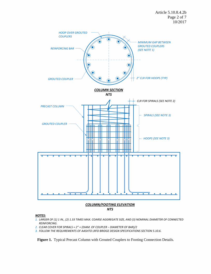
Minimum clear distance between grouted splice couplers is recommended to be the same as those specified for reinforcing bars. See typical detail drawings in Figure 1.
The clear cover for the shear reinforcement over grouted couplers in the precast column shall be 2”.
Grout for grouted couplers shall be provided by the manufacturer of the coupler. Table 1. List of Approved Grouted Couplers
ASTM A706 or ASTM A615 Grade 60 Bar Size
NMB Splice Sleeve Erico Lenton Interlok
#5 5U-X LK5 #6 6U-X LK6 #7 7U-X LK7 #8 8U-X LK8 #9 9U-X LK9
#10 10U-X LK10 #11 11U-X, SNX11 LK11 #14 14U-X LK14 #18 -- LK18
Article 5.10.8.4.2b Page 2 of 7
10/2017
Figure 1. Typical Precast Column with Grouted Couplers to Footing Connection Details.
NOTES: 1. LARGER OF (1) 1 IN., (2) 1.33 TIMES MAX. COARSE AGGREGATE SIZE, AND (3) NOMINAL DIAMETER OF CONNECTED
REINFORCING. 2. CLEAR COVER FOR SPIRALS = 2” + (DIAM. OF COUPLER – DIAMETER OF BAR)/2 3. FOLLOW THE REQUIREMENTS OF AASHTO LRFD BRIDGE DESIGN SPECIFICATIONS SECTION 5.10.6.
2” CLR FOR HOOPS (TYP)
MINIMUM GAP BETWEEN GROUTED COUPLERS (SEE NOTE 1)
HOOP OVER GROUTED COUPLERS
GROUTED COUPLER
REINFORCING BAR
COLUMN SECTION NTS
COLUMN/FOOTING ELEVATIONNTS
GROUTED COUPLER
HOOPS (SEE NOTE 3)
SPIRALS (SEE NOTE 3)
PRECAST COLUMN CLR FOR SPIRALS (SEE NOTE 2)

Article 5.10.8.4.2b Page 3 of 7
10/2017
1. Background Information on Grouted Coupler Dimensions and Comparison of Grouted Coupler Lengths: Figure 2 shows the connector configuration for the NMB Type U-X and A11W splice-sleeves. Figure 3 shows connector configuration for the NMB SNX11 splice-sleeve. Tables 2 and 3 show the dimensions and the required rebar embedment lengths corresponding to Figures 2 and 3, respectively.
Figure 2. NMB Type U-X and A11W Splice Sleeves. (ICC-ES Report ESR-3433, Splice Sleeve North America, Inc., 2016).
Figure 3. NMB SNX11 Splice Sleeve. (ICC-ES Report ESR-3433, Splice Sleeve North America, Inc., 2016).

Article 5.10.8.4.2b Page 4 of 7
10/2017
Table 2. Dimensions of NMB Type U-X and A11W Splice-Sleeves (ICC-ES Report ESR-3433, Splice Sleeve North America, Inc., 2016).

Article 5.10.8.4.2b Page 5 of 7
10/2017
Table 3. Dimensions of NMB SNX11 Splice-Sleeve (ICC-ES Report ESR-3433, Splice Sleeve North America, Inc., 2016).

Article 5.10.8.4.2b Page 6 of 7
10/2017
Figure 4 shows the connector configuration for Erico’s Lenton Interlok couplers and Table 4 shows the dimensions and cut length for reinforcing steel.
Figure 4. Erico’s Lenton Interlok Rebar Splicing System. (Erico, 2013).
Table 4. Coupler Dimensions and Cut Length for Reinforcing Steel for Lenton Interlok Rebar Splicing System. (Erico, 2013).

Article 5.10.8.4.2b Page 7 of 7
10/2017
Reference: Idaho Transportation Department Research Report, Report No. FHWA-ID-16-246: “Seismic Performance of Columns with Grouted Couplers in Idaho Accelerated Bridge Construction Applications” (Authors: Arya Ebrahimpour, Barbara E. Earles, Supreme Maskey, Maria Tangarife, Andrew D. Sorensen, Idaho State University Department of Civil and Environmental Engineering) Revisions: Oct 2017 New article prepared by Leonard Ruminski