
Arthroscopic Shoulder Repair Using the Smith & Nephew ...
12
Arthroscopic Shoulder Repair Using the Smith & Nephew FOOTPRINT PK Suture Anchor Shoulder Series Technique Guide
Transcript of Arthroscopic Shoulder Repair Using the Smith & Nephew ...

Arthroscopic Shoulder Repair Using the Smith & Nephew FOOTPRINT PK Suture Anchor
Shoulder SeriesTechnique Guide

Reviewed by:Michael Terry, MDAssistant Professor of Surgery, Sports MedicineUniversity of ChicagoHead Team Physician, Chicago BlackhawksChicago, IL
�
Arthroscopic Shoulder Repair Using the Smith & Nephew FOOTPRINT PK Suture Anchor
IntroductionThe Smith & Nephew FOOTPRINT PK Suture Anchor is intended to provide secure fixation of soft tissue to bone. The anchor’s unique design captures suture limbs from neighboring anchors, creating a suture pattern that provides compression of the rotator cuff tissue to the humeral head. A variety of final suture patterns is possible, allowing the surgeon to perform a fixation that is most appropriate for the particular cuff tear.
The key feature is the adjustability of the suture tension across the surface of the cuff tissue, even after the traditional fixation is completed using traditional suture anchors. The internal anchor plug securing the suture can be reversed, allowing an increase or decrease in tension on the suture that traverses the rotator cuff tendon, resulting in a repair without compromise.
Patient Positioning Place the patient in either the beach chair position or the lateral decubitus position.
Portal PlacementThe portals listed here are meant to be a guide to help the surgeon understand the basics of the anchor insertion.
Establish a standard posterior portal at the “soft spot.” The posterior portal is often used for arthroscopic visualization and for the initial repair preparation and subacromial decompression. Establish the lateral portal; referred to in this technique guide as the “primary portal.” The primary portal is typically created lateral to the acromion, in line with the posterior edge of the clavicle. The distance from the primary portal to the acromion is variable and is a matter of preference. Establish the “secondary” lateral portal in a position appropriate for the location of the rotator cuff tear (e.g., anterior-lateral or posterior-lateral). Typically the secondary portal is inferior and posterior to the primary portal. These portal locations are similar in the lateral decubitus and beach chair positions.
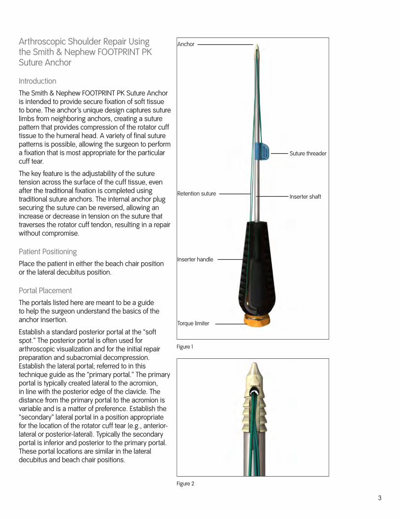
Figure 1
Anchor
Suture threader
Inserter shaft
Inserter handle
Torque limiter
Retention suture
Figure 2

�
Double Row Technique
1. Insert the medial anchors at the medial border of the rotator cuff footprint.
2. Use a Smith & Nephew ELITE-PASS™ Suture Shuttle to pass sutures up through the rotator cuff. If desired, tie off the sutures, but do not cut them.
Note: See the Appendix for different anchor options for the medial row.
�. Use an appropriate awl to prepare an anchor hole for the anchor in the humeral head. Locate the hole at the desired site on the lateral border of the rotator cuff footprint or lateral to the footprint (Figure �).
The proper hole depth is achieved when the laser depth mark or circular groove on the distal end of the awl contacts the bone surface. Remove the awl from the insertion site.
Note: Locating the anchor lateral to the rotator cuff footprint can provide an excellent option for patients with poor bone quality or if there are already other anchors in the immediate vicinity.
Note: The torque limiter, located at the proximal end of the inserter handle, is preset and should not be turned until the anchor has been fully seated and proper tension has been applied to the suture.
Note: For hard bone conditions the use of a drill is recommended for hole preparation. See the Technical Pearls section for details.
�. Push the suture threader down the inserter shaft, toward the anchor, to release the suture threading loop from the threader (Figure �).
5. Select the appropriate limbs of two sutures from either the implanted medial suture anchors or the sutures threaded through tissue. Bring these sutures out through the same portal used to create the tunnel.
Thread the two free ends through the suture threading loop, remove the suture threader tab from the shaft of the inserter and pull the tab away from the anchor to feed the sutures through the anchor (Figure 5).
Figure �
Figure �
Figure 5
Figure 6

5
6. Slide the loaded suture anchor into the joint through the portal used to create the starting tunnel and through which the sutures were retrieved. As the anchor advances toward the prepared bone tunnel, remove excess suture slack to minimize suture entanglement (Figure 6). If desired, secure the free ends of the suture using the features located on the inserter handle. Do not attempt to tension the sutures at this time.
7. Orient the anchor so that the medial suture limbs entering the anchor are facing the tissue and the sutures are not twisted around the anchor (Figure 7).
8. Establish and maintain axial alignment of the suture anchor to the prepared insertion site, and place the tip of the anchor into the prepared hole. Use a mallet to tap the inserter handle until the laser mark is flush with the cortical bone (Figure 8). This places the suture anchor approximately 1 mm below the bone surface (Figure 9).
Warning: Do not remove the retention suture from the inserter before the anchor is properly secured in the insertion site. The retention suture allows the anchor to be retrieved should the anchor disengage before inserting into bone.
9. Unhook the retention suture from the inserter handle, pull one end to remove the suture from the handle and anchor, and discard the retention suture. The retention suture must be removed prior to tensioning the medial suture limbs and turning the torque limiter to secure the limbs within the anchor.
Figure 8
Figure 9
Figure 7

6
10. Apply tension and lock the suture.
a. Maintain a slight downward pressure on the inserter handle and remove the free ends of the sutures from the inserter handle. Manually pull sutures (individually or together) to apply the desired tension (Figure 10).
b. If desired, secure the free ends of the tightened suture using the features located on the inserter handle. Maintain slight downward pressure on the inserter, locate the torque limiter knob on the proximal end of the inserter handle and rotate it clockwise (Figure 11). Continue rotating the knob until several clicks are heard. At this point, turning the knob will no longer advance the inner anchor plug.
c. Check the final repair and if the tension on the suture is not adequate, rotate the knob counterclockwise until the suture can slide easily.
Warning: Rotating the knob counterclockwise loosens the inner anchor plug. Excessive rotating counterclockwise can unscrew the plug and back it out of the implant threads. Rotate the knob only enough to allow the sutures to slide easily (approximately two rotations).
Repeat step “a” and “b” to apply appropriate tension and lock the suture. Repeat as necessary to achieve the desired repair.
Figure 11
Figure 10
7
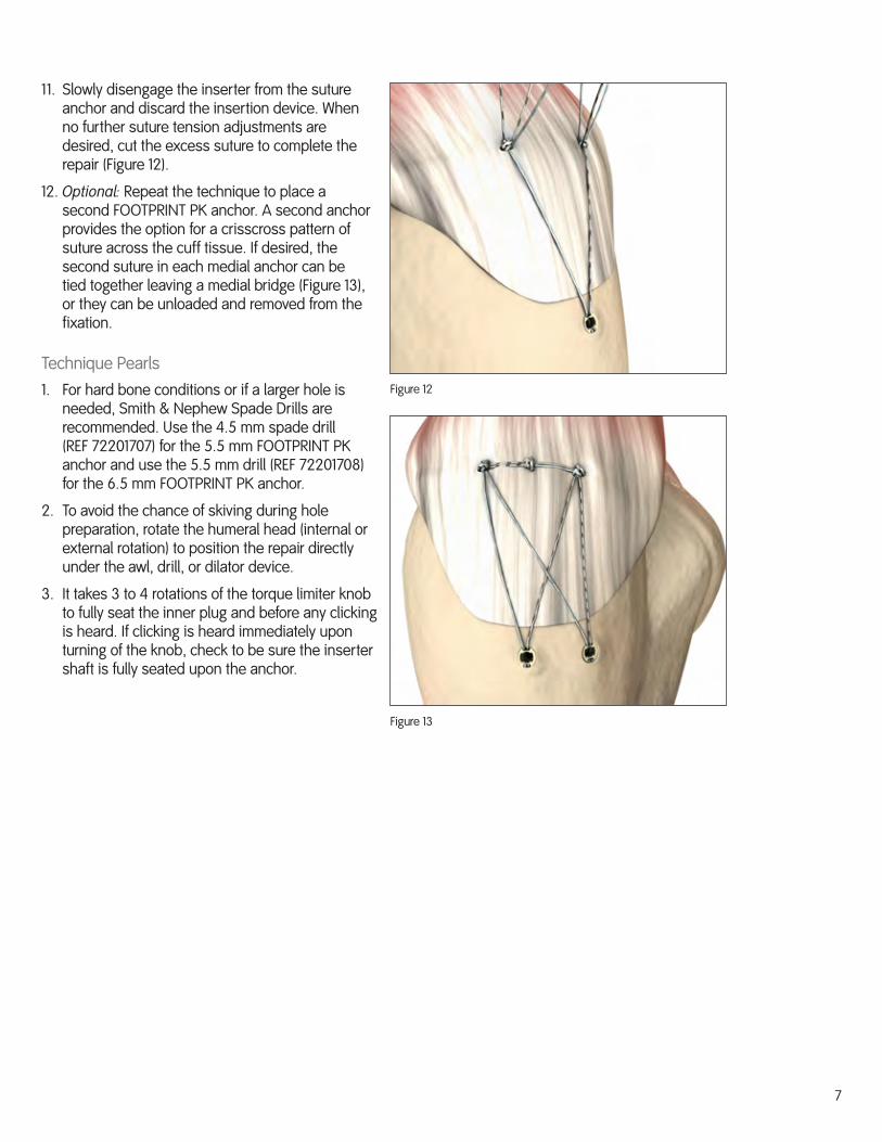
11. Slowly disengage the inserter from the suture anchor and discard the insertion device. When no further suture tension adjustments are desired, cut the excess suture to complete the repair (Figure 12).
12. Optional: Repeat the technique to place a second FOOTPRINT PK anchor. A second anchor provides the option for a crisscross pattern of suture across the cuff tissue. If desired, the second suture in each medial anchor can be tied together leaving a medial bridge (Figure 1�), or they can be unloaded and removed from the fixation.
Technique Pearls1. For hard bone conditions or if a larger hole is
needed, Smith & Nephew Spade Drills are recommended. Use the �.5 mm spade drill (REF 72201707) for the 5.5 mm FOOTPRINT PK anchor and use the 5.5 mm drill (REF 72201708) for the 6.5 mm FOOTPRINT PK anchor.
2. To avoid the chance of skiving during hole preparation, rotate the humeral head (internal or external rotation) to position the repair directly under the awl, drill, or dilator device.
�. It takes � to � rotations of the torque limiter knob to fully seat the inner plug and before any clicking is heard. If clicking is heard immediately upon turning of the knob, check to be sure the inserter shaft is fully seated upon the anchor.
Figure 12
Figure 1�
8
Appendix
Medial Anchor Insertion Techniques
Smith & Nephew KINSA™ RC Suture Anchor
While described in its technique guide as an anchor for use at the lateral row, the KINSA RC anchor can be used effectively as a medial row anchor that requires no knot tying.
1. Use an appropriate awl (also used for the FOOTPRINT PK Suture Anchor) to prepare a hole in the humeral head at the desired site on the medial row for the KINSA RC anchor. Use a mallet to tap the awl to the proper depth.
2. Remove the awl and advance the KINSA RC anchor into the joint to the prepared hole. Maintain axial alignment and place the anchor into the hole. Use a mallet to tap the anchor into the hole until the outer inserter shaft is sitting on the bone surface.
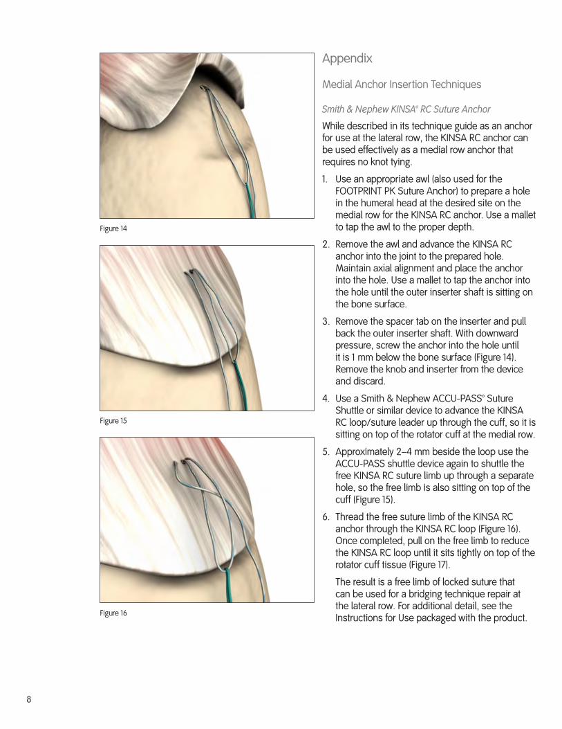
�. Remove the spacer tab on the inserter and pull back the outer inserter shaft. With downward pressure, screw the anchor into the hole until it is 1 mm below the bone surface (Figure 1�). Remove the knob and inserter from the device and discard.
�. Use a Smith & Nephew ACCU-PASS™ Suture Shuttle or similar device to advance the KINSA RC loop/suture leader up through the cuff, so it is sitting on top of the rotator cuff at the medial row.
5. Approximately 2–� mm beside the loop use the ACCU-PASS shuttle device again to shuttle the free KINSA RC suture limb up through a separate hole, so the free limb is also sitting on top of the cuff (Figure 15).
6. Thread the free suture limb of the KINSA RC anchor through the KINSA RC loop (Figure 16). Once completed, pull on the free limb to reduce the KINSA RC loop until it sits tightly on top of the rotator cuff tissue (Figure 17).
The result is a free limb of locked suture that can be used for a bridging technique repair at the lateral row. For additional detail, see the Instructions for Use packaged with the product.
Figure 1�
Figure 15
Figure 16
9
Figure 17
Smith & Nephew TWINFIX™ PK FT Suture Anchor
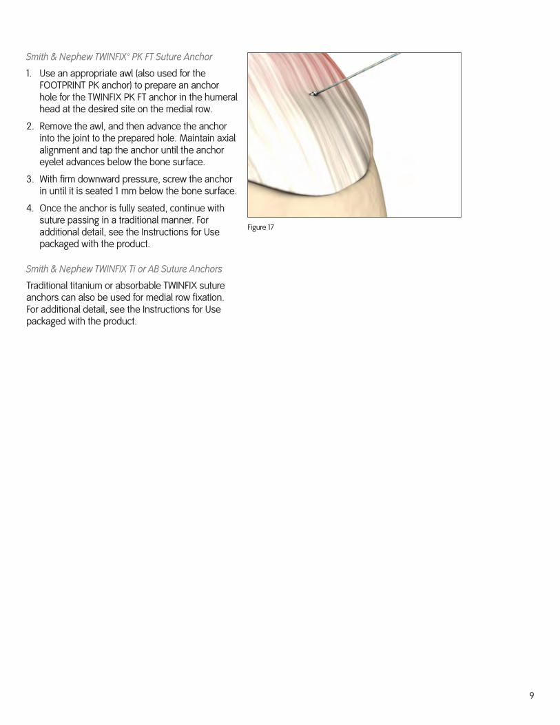
1. Use an appropriate awl (also used for the FOOTPRINT PK anchor) to prepare an anchor hole for the TWINFIX PK FT anchor in the humeral head at the desired site on the medial row.
2. Remove the awl, and then advance the anchor into the joint to the prepared hole. Maintain axial alignment and tap the anchor until the anchor eyelet advances below the bone surface.
�. With firm downward pressure, screw the anchor in until it is seated 1 mm below the bone surface.
�. Once the anchor is fully seated, continue with suture passing in a traditional manner. For additional detail, see the Instructions for Use packaged with the product.
Smith & Nephew TWINFIX Ti or AB Suture Anchors
Traditional titanium or absorbable TWINFIX suture anchors can also be used for medial row fixation. For additional detail, see the Instructions for Use packaged with the product.


EndoscopySmith & Nephew, Inc.Andover, MA 01810USA
www.smith-nephew.com+1 978 7�9 1000+1 978 7�9 1108 Fax+1 800 ��� 5717 U.S. Customer Service
Additional InstructionPrior to performing this technique, consult the Instructions for Use provided with individual components — including indications, contraindications, warnings, cautions, and instructions.
Courtesy of Smith & Nephew, Inc., Endoscopy Division
Caution: U.S. Federal law restricts this device to sale by or on the order of a physician.
0�/2008 10600288 Rev. A
©2008 Smith & Nephew, Inc.All rights reserved.
™ Trademarks of Smith & Nephew. Certain marks registered U.S. Patent & Trademark Office.


