Development Simulator: Development Simulator: A Tool for ...

Project Number: GRG-1204
Arterial Line Insertion Simulator A Major Qualifying Project Report:
Submitted to the Faculty
of the
WORCESTER POLYTECHNIC INSTITUTE
in partial fulfillment of the requirements for the
Degree of Bachelor of Science
By
_________________________
Rebecca Cunningham (BME)
Date: 26 April 2012
Approved:
________________________________
Prof. Glenn R. Gaudette, Major advisor
____________________________________
Dr. Mohammed Akhter (UMass), Co-advisor
_____________________________
Melinda Taylor (UMass), Co-advisor

2
Table of Contents Acknowledgements ....................................................................................................................................... 4
Abstract ......................................................................................................................................................... 5
Table of Figures ............................................................................................................................................. 6
Table of Tables .............................................................................................................................................. 7
Chapter 1. Introduction ................................................................................................................................ 8
Chapter 2. Literature Review ........................................................................................................................ 9
2.1 History ................................................................................................................................................. 9
2.2 Choice of Site ...................................................................................................................................... 9
2.3 Indications ......................................................................................................................................... 10
2.4 Potential Complications .................................................................................................................... 10
2.5 Radial Artery Anatomy ...................................................................................................................... 11
2.6 Allen’s Test ........................................................................................................................................ 11
2.7 Radial Line Procedure ....................................................................................................................... 12
2.8 Radial Arterial Waveform .................................................................................................................. 13
Chapter 3. Project Strategy ......................................................................................................................... 14
3.1 Initial Client Statement ..................................................................................................................... 14
3.2 Objectives .......................................................................................................................................... 14
3.3 Constraints ........................................................................................................................................ 17
3.4 Revised Client Statement .................................................................................................................. 18
3.5 Project Approach .............................................................................................................................. 18
Chapter 4: Alternative Designs ................................................................................................................... 19
4.1 Needs Analysis .................................................................................................................................. 19
4.2 Functions and Specifications ............................................................................................................. 20
4.3 Material and Pump Selection ............................................................................................................ 22
4.4 Alternative Designs ........................................................................................................................... 24
4.5 Preliminary Experiments ................................................................................................................... 27
4.6 Feasibility Study ................................................................................................................................ 28
4.7 Final Design ....................................................................................................................................... 29
4.8 Assembly of the Device ..................................................................................................................... 29
4.9 Controlling the Pinch Solenoid Valve ................................................................................................ 32
Chapter 5: Design Verification .................................................................................................................... 33

3
5.1 Nasco Tubing Performance Testing .................................................................................................. 34
5.2 Nasco Tubing Results ........................................................................................................................ 35
5.3 Pump Testing..................................................................................................................................... 35
5.3 Waveform Analysis ........................................................................................................................... 35
Chapter 6: Discussion .................................................................................................................................. 36
6.1 Simulator Performance ..................................................................................................................... 36
6.2 Limitations ......................................................................................................................................... 37
6.3 Economics ......................................................................................................................................... 37
6.4 Environmental Impact ....................................................................................................................... 37
6.5 Societal Influence and Political Ramifications .................................................................................. 38
6.6 Ethical Concerns ................................................................................................................................ 38
6.7 Health and Safety .............................................................................................................................. 38
6.8 Manufacturability .............................................................................................................................. 39
6.9 Sustainability ..................................................................................................................................... 39
Chapter 7: Final Design Validation .............................................................................................................. 39
Chapter 8: Conclusions and Recommendations ......................................................................................... 41
8.1 Conclusions ....................................................................................................................................... 41
8.2 Recommendations ............................................................................................................................ 42
8.3 Future Plans ...................................................................................................................................... 43
References .................................................................................................................................................. 44
Appendix A: Pairwise Comparison Charts ................................................................................................... 45
Appendix B: Performance Survey ............................................................................................................... 46
Appendix C: Arterial Line Insertion Simulator: User Guide......................................................................... 47

4
Acknowledgements
I would like to thank the American Medical Resource Foundation for providing me with pressure
transducers and an arterial line monitor.
I would also like to thank the following individuals:
Steven Cunningham, Manager of Clinical Engineering at the Milford Regional Medical Center,
for all of his help with this project especially the electronic components.
Melinda Taylor of the University of Massachusetts Medical School Simulation Center for
providing me with the materials necessary to complete this project.
Dr. Akhter of UMass Memorial for taking time out of his busy schedule to help with this project.
Professor Glenn Gaudette Ph.D. for advising this project.

5
Abstract
Arterial access is used to accurately measure and monitor blood pressure in real time. An
arterial line insertion simulator was designed to be an educational tool used to help train medical
professionals to insert radial arterial lines. This simulator was designed to be compatible with the
Seldinger or guidewire technique. An arm was constructed to have a radial artery with realistic
pulsatile flow. The simulator had a palpable pulse and flashback was present upon cannulation.
This simulator was compatible the placement of a radial arterial line using a 21 gauge needle,
0.018” guidewire and a 5 French catheter.

6
Table of Figures
Figure 1: The radial and ulnar arteries…………………………………………………………………………………………….……11
Figure 2: 5Fr and 6Fr radial arterial catheters……………………………………………………………………………….….….12
Figure 3: Characteristics of the radial arterial waveform…………………………………………………………….….……13
Figure 4: Objective Tree for the arterial line insertion simulator……………………………………………………….…16
Figure 5: Femoral Line Training Package……………………………………………………………………………………….…..…20
Figure 6: An evaluation of multiple materials considered weighing Young’s Modulus vs. price………......21
Figure 7: An evaluation of multiple materials considered weighing tensile strengths vs. price…….…..….22
Figure 8: Donated Nasco arm replacement skin…………………………………………………………………………….….…24
Figure 9: Pulsatile flow setup alternative #1…………………………………………………………………………………………25
Figure 10: Pulsatile flow setup alternative #2……………………………………………………………………….….………….26
Figure 11: Pulsatile flow setup alternative #3……………………………………………….……………………………….…….26
Figure 12: Pulsatile flow setup alternative #4 (Final Design)………………………………………………………….….…26
Figure 13: Waveform of pulsatile setup alternative #1……………………………………………………………...…………27
Figure 14: Waveform of pulsatile flow setup alternative #2…………………………………………………..…….………27
Figure 15: Pulsatile flow set up alternative #1 with opening and closing sprinkler valve………………………28
Figure 16: A schematic of the final design………………………………………………………………………………………..…..29
Figure 17: A vinyl glove filled with silicone……………………………………………………………………………….………..…30
Figure 18: Simulated joint, tubing and skin…………………………………………………………………………………….…....31
Figure 19: The pulsatile flow generator system……………………………………………………………………………...…….32
Figure 20: The soldered breadboard used to control the pinch solenoid valve……………………………….…….33
Figure 21: The strip chart recording of the simulated arterial line waveform…………………………………...….36
Figure 22: Dr. Hunt Anderson palpating the simulated radial artery for a pulse………………………….…..……39
Figure 23: Dr. Zahi Rafey inserting the guidewire into the simulated radial artery………………………..……...40
Figure 24: The simulated arm with a 5Fr in the radial artery………………………………………………………………….41
Figure 25: The completely assembled final simulator………………………………………………………………………..…..42

7
Table of Tables
Table 1: Comparison of common cannulation sites………………………………………………………………….……….……9
Table 2: Pairwise Comparison Chart for the Arterial Line Insertion Simulator……………………………......……16
Table 3: A list of specifications for various simulated parameters………………………………………………..….…..20
Table 4: Radial Artery Wall Properties…………………………………………………………………………………………..….…..21
Table 5: A cross list matrix of possible pump types………………………………………………………………..…………...…23
Table 6: A cross list matrix of possible materials used for simulating skin…………………………….…………...….23
Table 7: A cross list matrix of possible materials used for simulating muscle tissue…………………..…..……..23
Table 8: A cross list matrix of possible materials used for simulating the wrist joint………………..………..….23
Table 9: A cross list matrix of possible materials used for simulating blood vessels……………….………..……23
Table 10: Nasco Tubing Performance Results……………………………………………………………………………….……….35

8
Chapter 1. Introduction
Arterial access is the gold standard for accurately measuring and monitoring blood
pressure in real time. This type of monitoring is necessary during the assessment of critical
circulatory conditions or during critical surgical procedures. Arterial lines can be used to gain
access to arterial blood and can be used for multiple blood draws. Arterial lines can be inserted
into the radial, ulnar, brachial, axillary, dorsalis pedis, posterior tibial, and femoral arteries
(Hignett et al., 2006). In the United States approximately 8 million arterial catheters are placed
each year (Scheer et al., 2002).
The proper insertion of an arterial line requires multiple cannulation trials for impeccable
placement. However, there are risks associated with arterial line insertion so special training is
necessary to teach this procedure prior to trying it on patients. Potential complications include
hemorrhage, thrombosis, perforation or dissection of the artery (Burns et al., 2006). These
complications can require emergency surgery and may cause permanent vascular or nerve
damage. To minimize the risk of complications, doctors and other medical professionals must be
properly trained.
Hospitals have turned to the use of medical simulators (common ones resemble model
mannequins) to practice these procedures. These medical simulators are low-risk educational
tools. Currently, there are only a few simulator models that are compatible with the arterial line
placement procedure. Unfortunately, these simulators are expensive and are only available for
the placement of a femoral line (Vascular, 2011). Some arm simulators do exist for venous and
arterial access but these models are only compatible with arterial puncture and not the placement
of an arterial catheter.

9
The goal of this project is to create an Arterial Line Insertion Simulator for the University
of Massachusetts Medical School (UMMS) Simulation Center. This simulator is will be
developed to help train medical professionals to insert radial arterial lines. My clients are Dr.
Akhter of the University of Massachusetts Memorial Medical Center and Melinda Taylor of the
UMMS Simulation Center.
Chapter 2. Literature Review
2.1 History
In 1989 Dr. Lucien Campeau was one of the first doctors to attempt to place a catheter in
the radial artery. He attempted to place a catheter in the radial arteries of 100 patients (Campeau,
1989). He successfully placed 88 catheters. The radial artery is now the most common choice of
site for arterial cannulation.
2.2 Choice of Site
Table 3: Comparison of common cannulation sites
Arterial catheters can be placed in the femoral, radial, axillary, brachial, ulnar, dorsal
pedis, tibial posterior and temporal arteries. The two most commonly cannulated arteries for
Site Advantage Disadvantages
Radial Artery Ease of placement
Relatively accurate
Presence of collateral flow
If short catheter is used the BP may be underestimated on high dose vasopressors in septic patients
Femoral Artery Relatively easy artery to cannulate
More accurate in sepsis when high does vasopressors are used
Increased risk of infection
Patient leg motion can be problematic

10
haemodynamic monitoring are the radial and femoral arteries (Table 1). Femoral line placement
is slightly more invasive than radial line placement and has a risk of more serious complications.
The risk of infection is greater for the femoral line procedure because there is a higher density of
microbes in the groin area (Scheer et al., 2002).
2.3 Indications
Arterial access is used for continuous haemodynamic monitoring in the operating room
during major surgery involving blood loss or fluid shifts in critically ill patients. It can also be
used to monitor patients with haemodynamic instability requiring inotropic or vasopressor
medications. Arterial catheters can be used to gain access to arterial blood which can be used for
an arterial blood gas. This test is commonly and frequently performed on patients in the intensive
care unit (ICU) (Martin et al., 2001).
2.4 Potential Complications
There are many complications associated with arterial cannulation. Potential
complications include arterial spasm, haematoma, haemorrhage, temporary occlusion,
thrombosis, permanent ischemic damage, local infection, sepsis, pseudoaneurysm, arteriovenous
formation, nerve damage, and retained guidewire (Scheer et al., 2002).These complications are
serious and some of them have the potential to be life threatening. These complications can often
require emergency surgery and may lead to a loss of digits. However, these complications occur
in less than 1% of cases (Scheer et al., 2002). The most common complication of radial artery
cannulation is temporary occlusion. This is not a major problem provided that there is adequate
collateral flow via the ulnar artery (Cousins et al., 2004).

11
2.5 Radial Artery Anatomy
The radial artery is a continuation of the brachial
artery (Fig. 1). It arises at the bend of the elbow in the
antecubital fossa and passes along the radial side of the
forearm to the wrist. It is just lateral to the flexor carpi
radialis tendon on the thumb side. Collateral circulation is
provided by the ulnar artery and palmar arch (Cousins et
al., 2004).
Pulsations can be palpated at approximately 2cm
from the wrist, where the artery becomes superficial as it
passes over the radius bone. The radial artery then
anastomoses with the ulnar artery in the hand forming the
deep palmar arch, the dorsal arch and the superficial
palmar arch (Malley, 2004).
2.6 Allen’s Test
Allen’s test or a modified Allen’s test is performed
to verify that there is collateral circulation prior to radial
line insertion. Poor collateral circulation is present in about 12% of people (Hignett et al., 2006).
If ulnar perfusion is poor then when a cannula occludes the radial artery, the blood flow to the
hand may be compromised.
Allen’s test is performed by asking the patient to clench their hand. The ulnar and radial
arteries are then occluded by applying pressure. Next the hand is unclenched and the pressure
used to occlude the ulnar artery is released. If there is good collateral circulation, then the palm
Figure 13: The radial and ulnar arteries (Gray, 2000)

12
should flush in less than 6 seconds (Hignett et al., 2006).
2.7 Radial Line Procedure
There are several different methods used to insert arterial catheters. Choice of method is
dependent on the clinician’s experience and preferences. Two common techniques are the
catheter-over-needle technique and the catheter-over-guidewire or Seldinger technique. Arterial
access typically uses a 20Ga or smaller needle. Radial arterial catheters range in size from 4-7
French (Fr) (Fig.2). The length of the catheter varies but is usually at least 10cm. Guidewires
used for radial access are 0.018-0.025".
Figure 14: 5Fr and 6Fr radial arterial catheters
Before the procedure begins the patient should be prepped. The insertion site should be
cleaned with an antiseptic. Pain can be managed by using a local anesthetic and/or sedation. The
hand should be placed in moderate dorsiflexion so that the radial artery is closer to the surface of
the skin (Malley, 2004). The major landmarks should be identified as the radial artery is palpated
for a pulse.
Catheter-over-needle technique
The cannula is inserted aiming to hit the middle of the artery at an angle of approximately
30 ° to the skin. When there is a flashback of arterial blood back into the hub of the cannula, the
cannula sheath is advanced over the needle into the artery (Hignett et al., 2006).

13
Catheter-over-guidewire (Seldinger) technique
The cannula is inserted at a 45° angle with the skin. After the flashback the cannula is
lowered to a 30° angle. The guidewire is then inserted into the lumen through the cannula needle.
The guidewire should advance easily along the artery. The cannula sheath is then advanced along
the artery, and the guidewire is removed.
2.8 Radial Arterial Waveform
Once the radial arterial catheter is placed it is hooked up to an arterial giving set, pressure
transducer and monitor. The column of saline in the arterial giving set transmits the pressure
changes to the diaphragm in the transducer. This produces an electrical signal which is displayed
as an arterial waveform (Hignett et al., 2006). The radial artery is a peripheral artery. Peripheral
arterial waveforms have a higher peak systolic pressure, a wider pulse pressure and a more
prominent dicrotic notch than central arterial waveforms. These waveform differences are the
result of the peripheral arteries being smaller and less compliant than the central arteries (Hignett
et al., 2006).
Figure 15: Characteristics of the radial arterial waveform (Mills, 2008)

14
Arterial waveforms can provide useful information in addition to blood pressure
measurement. The shape of the arterial waveform can provide information about myocardial
contractility and hypovolaemia. Myocardial contractibility is indicated by the slope (dP/dt) of the
arterial upstroke. A narrow waveform with a low dicrotic notch and a peak pressure that varies
with intermittent positive pressure ventilation breaths (if the patient is ventilated), or with deep
inspirations in a breathing patient is an indicator of hypovolaemia (Hignett et al., 2006).
Chapter 3. Project Strategy
3.1 Initial Client Statement
Over the summer the UMMS Simulation Center gave me the following project
description:
“Monitoring patients can sometimes include access to arterial blood. This is usually
accomplished through the placement of an arterial line in either the arm of leg of a
patient. There currently exists a need for an improved arterial line placement simulator.
This project will design a model (and build prototype) to simulation arterial line
insertion. It should incorporate pulsatile flow, be anatomically correct, and simulate the
human arm in regards to the biomechanical response of skin, muscle and blood vessels.”
From this description I determined the initial client statement to be:
“Design a realistic model and develop a prototype that is used to simulate the insertion
of an arterial line. The model should incorporate pulsatile flow, be anatomically correct
and simulate the biomechanical response of skin, muscle and blood vessels.”
3.2 Objectives
The project objectives and constraints were determined through research and several
meetings with my clients. It was determined that the simulator should model the insertion of a
radial arterial line as opposed to a femoral line. The budget for this project was $156.00 since
there was no external sponsorship. The deadline for project completion was April 26, 2012.

15
The simulator should be a useful educational tool. In order to be useful the simulator
must accurately model the arm and radial artery. The simulated tissues must behave in the same
manner as the skin, vessel wall, fascia, muscle and bone of an arm. Also, in order to be a useful
educational tool the simulator must be compatible with the current equipment and materials that
are actually used to insert an arterial line. The simulator should be compatible with the Seldinger
or guidewire technique. This will allow learners to become familiar with the materials and
equipment used in the real procedure.
The simulator should be realistic. It must have pulsatile flow. The simulator must be
pressurized so that when the needle is inserted into the radial artery there is a flashback of
simulated blood. The simulator does not have to have the same blood pressure as a normal
human. There should be a “pop” sound when the skin and vessels are punctured. The tubing in
the simulator should have a response similar to the physiological response of arteries. The tubing
should expand and contract slightly as the simulated blood pulses. Other potential objectives that
were discussed included making the pulse both automated and adjustable.
The simulator should be user-friendly. It should be safe, easy to assemble and reusable.
To make the simulator reusable it should be composed of durable materials and some easily
replaceable parts. It should be robust and capable of approximately 200 arterial insertions before
the parts need to be replaced. To ensure that the simulator is safe it should use environmentally
friendly, non-carcinogenic materials. The simulated blood should not be toxic or harmful to the
eyes. The simulator should have proper warning labels for allergenic materials such as latex.
The simulator should have market potential. It should demonstrate a “proof of concept”
that can be reproduced. It should incorporate as many “off the shelf” parts as possible. It should
have the potential to be manufactured. According to my clients manufacturability is one of the

16
least important objectives for my project. The proof of concept should be demonstrated as
cheaply as possible. The simulator should be fairly inexpensive (<156$).
Figure 16: Objective Tree for the arterial line insertion simulator
Table 4: Pairwise Comparison Chart for the Arterial Line Insertion Simulator Objectives Useful Realistic User-Friendly Marketable Total
Useful xxx 0 1 1 2
Realistic 1 Xxx 1 1 3
User-Friendly 0 0 Xxx 1 1
Marketable 0 0 0 Xxx 0
A pairwise comparison chart (PCC) was used to determine which of the primary
objectives take precedence (Table 2). The objectives were compared and ranked by the clients. It
Arterial Line Insertion Simulator
Useful
Accurate Anatomically
correct
Precise
Equipment Compatible
Realistic
Flashback
Pulsatile Flow
Automated
Adjustable
"Pop" Sound
User-Friendly
Safe
Environmentally Friendly
Non-carcinogenic
Easy to assemble
Portable
Replaceable Parts
Reusable
Robust
Durable
Marketable
Manufacturable
Inexpensive

17
was determined using the PCC that the most important objective was that the simulator be
realistic. The second most important objective was the usefulness of the simulator as an
educational tool. The simulator should still be user-friendly and marketable, but these objectives
were ranked behind the “realistic” and “useful” objectives. Additional pairwise comparison
charts are shown in Appendix A.
3.3 Constraints
The major constraints of this project were time and money. I was limited by a budget of
$156 because UMMS did not provide sponsorship for the initial prototype. My budget limited
the types of pumps I could utilize in my design since some pumps are expensive. However, if I
successfully create a “Proof of Concept” then I can apply for funding through UMMS. The
deadline for this project was April 26, 2012. Another time constraint was the limited face time
with my client Dr. Akhter. Dr. Akhter has a very busy schedule since he specializes in both
cardiovascular disease and interventional cardiology.
Safety was both an objective and a constraint since it limited the materials that I could
use. I could not use any materials that were hazardous to the environment or to the health of the
user. This meant no carcinogenic talcum powder or potentially blinding simulated blood. I used
allergenic materials such as latex but proper warning labels were implemented.
I was able to use “off the shelf” parts but I could not use ideas that are already patent
protected. HIPPA laws (patient confidentiality) were also a constraint because they limited the
amount I could learn about the patients I observed in the catheterization lab. Another constraint
was size. The arm could not have larger dimensions or weigh more than the average arm. The
pump could be outside the arm but it should not be excessively bulky since the simulator should
be portable.

18
3.4 Revised Client Statement
Taking the established objectives and constraints into account I was able to revise the client
statement. My revised client statement was:
“Design an anatomically and physiologically realistic arm that includes the radial
artery. Develop a working prototype that is used to simulate the insertion of an arterial
line through the radial artery. The simulator should have pulsatile flow, a palpable pulse,
and demonstrate a realistic flashback and “pop” upon cannulation.”
3.5 Project Approach
I began my project with a general project statement from my clients. I then met with my
clients in an orientation meeting to define the problem. My clients informed me of some of the
resources available to me through UMMS. These resources include being able to observe
procedures at the cardiac catheterization lab and perform procedures in the cadaver lab. Before
the second meeting I immersed myself in literature related to my topic. I also examined current
products and patents that pertained to my project (benchmarking). My second meeting was a
structured client interview in which I was able to clarify the project objectives and identify
constraints.
From my list of objectives I built an objectives tree. In the third client meeting my clients
filled out pairwise comparison charts to help rank the objectives. To help manage my project I
created a Gantt Chart using Microsoft Project. I also created a Work Breakdown Structure. I
used enumeration to identify a list of functions for my simulator. From my list of functions I then
created a function-means tree.
To expand my design space I tried thinking outside the box to help me come up with
design alternatives. I used the C-sketch and Gallery methods to help generate design alternatives.
In my next client meeting we selected a design from the design alternatives. I built the prototype
using the selected design.

19
I also used the age old philosophy in the medical community of “see one, do one, teach
one”. This approach helped me to become familiar with the arterial line procedure so that I
could evaluate and test my prototype. I was able to “see one” and “do one” using the resources
available to me at UMMS. I observed Dr. Akhter place a radial arterial line in the cardiac
catheterization lab. I also got to dissect down to the radial artery in the cadaver lab.
It was not possible for me to actually place an arterial catheter in the cadaver’s radial
artery because cadavers do not have a blood pressure. I was able to visualize the radial artery and
surrounding anatomy. This helped me to place the radial artery in my simulator. This approach
gave me a unique prospective that helped me to evaluate and test my prototype.
Chapter 4: Alternative Designs
4.1 Needs Analysis
The UMMS Simulation Center has several arm simulators. These simulators are capable
of venous and arterial puncture exercises. However, they are not compatible with arterial catheter
placement. This is a common finding in the medical simulation industry.
Currently, arterial access simulators do exist for femoral line placement. These simulators
are ultrasound compatible and expensive. Simulab Corporation’s femoral line training package is
$1,643.00 (Fig. 5) (Femoral, 2011). Radial arterial lines are typically placed without ultrasound
or fluoroscopy so proper placement is dependent on the clinician’s skill. Since my simulator does
not need to be ultrasound compatible I was able to make it cheaper than the femoral line
simulators.

20
Figure 17: Femoral Line Training Package (Femoral, 2011)
4.2 Functions and Specifications
A. The simulator should be anatomically and physiologically accurate.
The term “accurate” is subjective and needs a refined definition. Only certain aspects of
the simulator must be accurate to meet the needs of my clients. Based on discussions with my
clients I have determined that the following aspects of the simulator need to be “accurate”:
1. The simulation needs to have a radial artery in order to simulate the procedure.
The radial artery must be properly positioned in the arm. The radial artery should be 30cm
long have a diameter of approximately 3mm and a thickness of 1mm (Table 4).
2. The simulation’s circulation through the radial artery should be realistic.
There must be a palpable pulse at the site of the radial artery. The blood pressure should be
within human physiological range (Table 3). This will ensure realistic flashback.
3. The simulator should have a wrist joint.
The wrist joint should be capable of doing 90⁰ of wrist flexion and extension. Wrist rotation
is not necessary for this simulator.
Table 3: A list of specifications for various simulated parameters Parameters Human Range Specified Range
Diastolic Pressure 60-120mmhg -25-220mmhg
Systolic Pressure 90-210mmhg 50-250mmhg
Pulse rate 40-220bpm 50-160bpm

21
Table 4: Radial Artery Wall Properties Parameters Human Range Specified Range
Internal Diameter 2.11±0.56mm 1.5<x<2.5mm
External Diameter 3.10±0.65mm 3<x<3.5mm
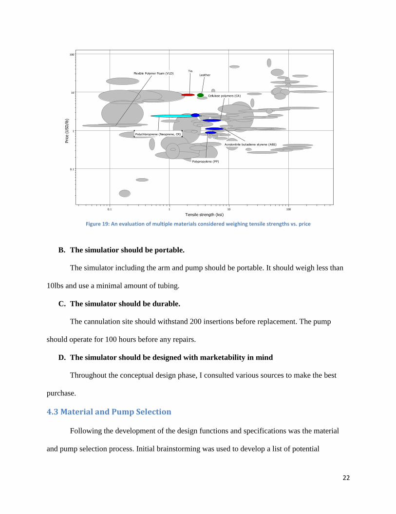
4. The arm’s soft tissues should have realistic pliability.
The simulated skin should behave like human skin. It should have a similar puncture
resistance to human skin and make a “pop” sound when it is punctured. A variety of
materials were evaluated using Granta’s CES EduPack. The Young’s Modulus of skin is
approximately 100KPa. 100KPa was used as a reference value to help find materials with a
similar Young’s Modulus (Fig. 6). The ultimate tensile strength of skin is between 5-30MPa.
Materials that fell within this range for ultimate tensile strength are displayed in Figure 7.
The skin should tightly hold the simulated tissues of the muscle, bone, and blood vessel in
place.
Figure 18: An evaluation of multiple materials considered weighing Young’s Modulus vs. price
Young's modulus (10^6 psi)
1e-4 0.001 0.01 0.1 1 10 100
Price
(U
SD
/lb)
0.1
1
10
100
Starch-based thermoplastics (TPS)
Polychloroprene (Neoprene, CR)
TinCellulose polymers (CA)
Polypropylene (PP)
Acrylonitrile butadiene styrene (ABS)
Leather
22
Figure 19: An evaluation of multiple materials considered weighing tensile strengths vs. price
B. The simulatior should be portable.
The simulator including the arm and pump should be portable. It should weigh less than
10lbs and use a minimal amount of tubing.
C. The simulator should be durable.
The cannulation site should withstand 200 insertions before replacement. The pump
should operate for 100 hours before any repairs.
D. The simulator should be designed with marketability in mind
Throughout the conceptual design phase, I consulted various sources to make the best
purchase.
4.3 Material and Pump Selection
Following the development of the design functions and specifications was the material
and pump selection process. Initial brainstorming was used to develop a list of potential
Tensile strength (ksi)
0.1 1 10 100
Price
(U
SD
/lb)
0.1
1
10
100
Polychloroprene (Neoprene, CR)
Flexible Polymer Foam (VLD)
Polypropylene (PP)
Acrylonitrile butadiene styrene (ABS)
Cellulose polymers (CA)
Leather
Tin

23
candidates that could fulfill the design requirements. The list was then put through a cross list
matrix (Tables 5-9). Based on the results of the cross list matrix, I decided that a hybrid drive
pump would be the best choice for this project. For the following metrics, 10 indicates the best,
and 1 the worst.
Table 5: A cross list matrix of possible pump types
Table 6: A cross list matrix of possible materials used for simulating skin Skin Tissue Pliability Cheap Total
Neoprene 7 4 11
Leather 3 3 6
Latex 10 7 17
Table 7: A cross list matrix of possible materials used for simulating muscle tissue
Muscle
Tissue
Cheap Durable Total
Silicone
Rubber
1 9 10
Foam 3 9 12
Clay 4 4 8
Cornstarch 10 1 11
Table 8: A cross list matrix of possible materials used for simulating the wrist joint Bone Material Malleability Cheap Durable Total
Plastic 6 10 10 26
Wood 10 10 9 29
Metal 7 7 10 24
Table 9: A cross list matrix of possible materials used for simulating blood vessels Vessel
Material
Durability Cheap Total
Vinyl 9 4 13
Silicone 8 5 13
Latex 8 3 11
Pump Types Automatic Cheap Configurability Total
Hybrid Drive 10 10 10 30
Peristaltic 10 9 10 29
Diaphragm 10 0 0 10
Turkey Baster 0 10 0 10
Rotary Vane 10 2 3 15
Centrifugal 10 0 2 12

24
4.4 Alternative Designs
Due to the vast similarities between the human arms, there are
few alternative concepts to the development of a human arm. My client,
Melinda Taylor, provided me with a Nasco Life/form injectable training
arm replacement skin (Fig. 8) and artery tubing. The Nasco injectable
training arm costs over 500$. The replacement skin and artery alone are
worth over 120$. This was a very generous donation to my project so my
final design utilized these materials.
Since I decided to use the Nasco replacement skin and artery
tubing this left me to determine the appropriate soft tissue and wrist joint
design. Alternative materials for the soft tissue were clay, foam, silicone
rubber and cornstarch. Based on the cross list matrix I decided that memory foam was the best
alternative. Memory foam is cheap and it took the shape of an arm once it was placed inside the
arm skin. Alternative designs for the wrist joint included a hinge joint constructed of various
materials. I decided to use a modified metal bicycle kickstand because metal is extremely
durable and was readily available.
One of the most important requirements of my simulator was pulsatile flow. Pulsatile
flow can be generated using a pump and system of valves. The hybrid drive pump scored the
highest in the decision matrix so all of my pulsatile flow setup alternatives utilized this type of
pump.
Figure 20: Donated Nasco arm replacement skin

25
Figure 21: Pulsatile flow setup alternative #1
The pulsatile flow setup alternative #1 (Fig. 9) required that the sprinkler valve to remain
in the open position during the simulation. The anesthesia machine tubing was blocked off at the
end with a cork and acted with the sprinkler valve to create oscillations. Anesthesia machine
tubing was used to create an expansion chamber. The expansion chamber was used to increase
the rise time making the pulse more palpable. Alternatives #2, #3 and #4 required the sprinkler or
pinch solenoid valve to open and close at a specific rate to create pulsatile flow. The difference
between alternative #2 (Fig. 10) and alternative #3 (Fig. 11) is that alternative #3 used a pinch
solenoid valve instead of a sprinkler system valve. The pinch solenoid valve was chosen to create
a fast enough rise time for a palpable pulse. Pulsatile flow setup alternative #4 used a system of
three needle valves to control the simulated pressure (Fig 12).

26
Figure 22: Pulsatile flow setup alternative #2
Figure 23: Pulsatile flow setup alternative #3
Figure 24: Pulsatile flow setup alternative #4 (Final Design)

27
4.5 Preliminary Experiments
Initially, I built pulsatile flow setup alternative #1. This design created very high
pressures making the pulse palpable (Fig. 13). However, because the sprinkler valve remained
open at all times, I could not control the pulse rate. This setup had a pulse of 200bpm with a
maximum pressure of 275mmhg. This pressure was measured by occluding the output of the
system and using the arterial line setup to measure the pressure. The maximum pressure of the
pump was high enough to create a palpable pulse
Figure 13: Waveform of pulsatile setup alternative #1
I then assembled pulsatile flow setup alternative #2. This design was able to create
physiological pressures of 120mmhg/80mmhg. It also created pressures that were higher than
that. However, the arterial waveform had a very slow rise time so the pulse was not palpable
even at 214mmhg/205mmhg (Fig. 14).
Figure 14: Waveform of pulsatile flow setup alternative #2

28
The resistance of the open sprinkler valve was found to be too high for the rapid rise time
required to create a palpable pulse. Figure 15 shows a waveform of pulsatile flow setup
alternative #1 when the sprinkler valve is opened and closed. This waveform was close to what I
wanted for my pulsatile flow setup. This indicated that replacing the sprinkler valve would likely
result in a system with the desired waveform/rise time.
Figure 15: Pulsatile flow set up alternative #1 with opening and closing sprinkler valve
4.6 Feasibility Study
The preliminary experiments were performed to determine if it would be possible to meet
my client’s needs without using a pinch solenoid valve. Pinch solenoid valves are expensive.
Based on the results of the preliminary experiments it was clear that I would need to purchase a
pinch solenoid valve to achieve a controllable palpable pulse in my simulator. I purchased a Cole
Parmer normally close pinch solenoid valve for 119$ which put me over budget.

29
4.7 Final Design
Figure 16: A schematic of the final design
Pulsatile flow setup alternative #4 was selected to be the final design. Pond Pump 560gph
by smartpond was used in this design. This pump has a maximum flow rate of 560 gallons per
hour at a 1ft height. The final design included a pinch solenoid valve, and a system of three
needle valves (Fig. 16). The pinch solenoid valve was used to control the pulse rate. The system
of needle valves was used to control the simulated pressure.
4.8 Assembly of the Device
The arm
1. The wrist joint was simulated using metal. Although wood and plastic scored higher in
the cross list matrix, a metal joint can provide more support. The bone does not need to
have a radius and an ulna it simply needs to support the soft tissue and have a joint that
does 90° of extension and 90° degrees of flexion. The bone was constructed from a

30
modified bicycle kickstand and was about 30cm in length. A hollow metal rod was
soldered to the end of the kickstand to extend it the full length of the arm.
2. The bone was covered by Silopad Body Discs coated in rubber cement. Silopad Body
Discs were used only to coat the bone near the site of cannulation. Memory foam was used
to fill in the other soft tissue.
3. The tissue of the hand was constructed from a vinyl glove filled silicone (Fig. 17).
4. A screw was embedded in the thumb of the simulated hand and attached to the modified
kickstand.
Figure 17: A vinyl glove filled with silicone
5. The Nasco tubing was connected to ¼” vinyl tubing at the top of the thumb by a nylon
hose barb connector. The ¼” tubing was attached to the back of the hand and metal rod
using plastic tie wraps (Fig. 18).
6. Memory foam was wrapped around the metal rod, kickstand and ¼” tubing to simulate
the remaining soft tissue of the arm.

31
7. The Nasco tubing was positioned on the surface of the memory foam where the radial
artery would be.
8. A nylon compressive covering was used to bind the simulated soft tissues.
9. The resulting arm was lubricated using petroleum jelly and the Nasco skin was slid over
the simulated hand and arm. The skin was tied tightly at the end opposite the hand.
Figure 18: Simulated joint, tubing and skin
The pulsatile flow generator (Fig.19)
1. The hybrid drive pond pump was submersed in a bucket of water.
2. Needle valve #1 was connected to the pump using bubble tubing and metal cable ties.

32
3. A three way splitter was connected after needle valve #1 to divert some of the flow to
needle valve #2.
4. The pinch solenoid valve was connected after the three way splitter to bubble tubing
which ran out of the bucket and up to the arm.
5. At the base of the arm a pressure sampling port was hooked up to a pressure transducer to
measure the simulated pressure.
6. The Nasco tubing was attached to the pressure sampling port and to the ¼” vinyl tubing
using nylon hose barb connectors.
7. The ¼” tubing ran from the arm back into the bucket.
8. Needle valve #3 was connected to the end of the ¼” tubing using metal cable ties.
Figure 19: The pulsatile flow generator system
4.9 Controlling the Pinch Solenoid Valve
An electronic control circuit was required to control the pinch solenoid valve. The design
parameters required a fixed pulse width of approximately 250ms and a variable pulse rate within
physiological range. The final design range was found to operate between 52bpm and 157bpm.

33
The pinch solenoid valve operates at 4watts and 12V DC. A 12V DC, 3.2A, laptop computer
power supply was used to power the electronic control circuit. A 556 timer circuit, which
consists of a dual 555 timers, was used to control the pinch solenoid valve (Fig.17). A Darlington
pair transistor was connected to the output of the 556 timer circuit to provide the necessary
current for the pinch solenoid valve.
Figure 20: The soldered breadboard used to control the pinch solenoid valve
Chapter 5: Design Verification
Since Melinda Taylor provided me with the Nasco arm skin and artery replacement
tubing, I did not need to verify/quantify that these materials make a realistic “pop” sound upon
cannulation. These materials are marketed as having a realistic “pop” sound when they are
punctured. These materials are used frequently and successfully at the simulation center. The
simulation industry often utilizes materials that do not necessarily have the same mechanical
properties as human tissue, but have properties that make them desirable in simulations. An
34
example of a desirable property of the Nasco arm skin is that it reseals after being punctured with
a needle.
Verification of a palpable pulse and flashback upon cannulation were determined
qualitatively. Once the simulator was assembled I felt for a pulse and placed several arterial
catheters in the simulated radial artery. I observed that there was in fact a palpable pulse and
flashback.
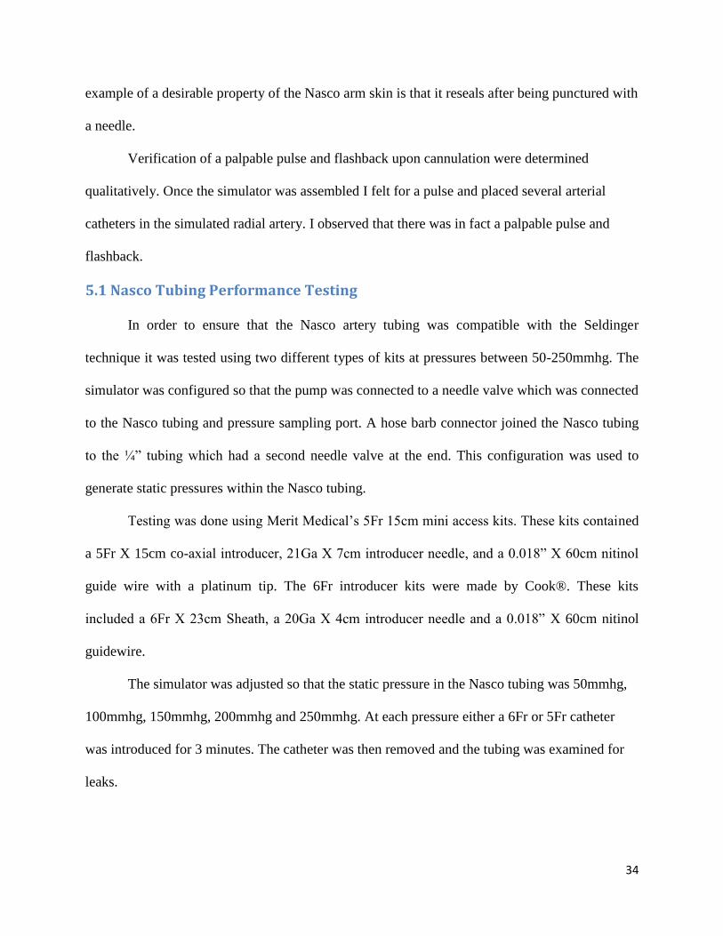
5.1 Nasco Tubing Performance Testing
In order to ensure that the Nasco artery tubing was compatible with the Seldinger
technique it was tested using two different types of kits at pressures between 50-250mmhg. The
simulator was configured so that the pump was connected to a needle valve which was connected
to the Nasco tubing and pressure sampling port. A hose barb connector joined the Nasco tubing
to the ¼” tubing which had a second needle valve at the end. This configuration was used to
generate static pressures within the Nasco tubing.
Testing was done using Merit Medical’s 5Fr 15cm mini access kits. These kits contained
a 5Fr X 15cm co-axial introducer, 21Ga X 7cm introducer needle, and a 0.018” X 60cm nitinol
guide wire with a platinum tip. The 6Fr introducer kits were made by Cook®. These kits
included a 6Fr X 23cm Sheath, a 20Ga X 4cm introducer needle and a 0.018” X 60cm nitinol
guidewire.
The simulator was adjusted so that the static pressure in the Nasco tubing was 50mmhg,
100mmhg, 150mmhg, 200mmhg and 250mmhg. At each pressure either a 6Fr or 5Fr catheter
was introduced for 3 minutes. The catheter was then removed and the tubing was examined for
leaks.

35
5.2 Nasco Tubing Results
The 20Ga/6Fr kits caused the tubing to leak at pressures as low as 100mmhg (Table 10). Since
the 20Ga/6Fr kits caused the tubing to leak at pressures below physiological pressure it is
recommended that only 21Ga/5Fr kits be used on the simulator at pressures below 200mmhg.
Table 10: Nasco Tubing Performance Results
Pressure
(mmhg)
Needle Gauge (Ga)/
Catheter size (Fr)
Observation
50 21/5 No leakage
50 20/6 No leakage
100 21/5 No leakage
100 20/6 Slow leak
150 21/5 No leakage
150 20/6 Slow leak
200 21/5 Slow leak
200 20/6 Fast leak
250 21/5 Slow leak
250 20/6 Fast leak
5.3 Pump Testing
To verify that the hybrid drive pump was capable of generating high enough pressures
testing was done. The flow was occluded completely closing needle valve #2 and needle valve
#3. This made it possible to measure the maximum pressure of the pump. The maximum
pressure of the pump was measured from the pressure sampling port and was determined to be
275mmhg. Since 275mmhg is higher than the physiological range for both systolic and diastolic
pressures, I was able to verify that Pond Pump 560gph meets the requirements of my simulator.
5.3 Waveform Analysis
An arterial catheter was placed in the simulated radial artery. This catheter was then
hooked up to a pressure transducer and monitor. This allowed me to confirm that the simulated
waveform from the arterial line corresponded directly to the waveform from the pressure

36
sampling port. This also allowed me to verify that the simulated waveform resembled a typical
radial arterial waveform (Fig. 21).
Figure 21: The strip chart recording of the simulated arterial line waveform
Chapter 6: Discussion
6.1 Simulator Performance
Based on the results of the Nasco tubing testing, pump testing and waveform analysis this
simulator met my clients’ objectives. The results of the Nasco tubing testing indicated that the
simulator was compatible with the placement of a 5Fr catheter using the Seldinger technique as
long as the simulated pressure did not exceed 200mmhg.
The pump testing demonstrated that the pump was capable of generating pressures higher
than the physiological range of human blood pressure. The simulated waveform closely
resembled an arterial waveform. There was even an accidental dicrotic notch. This was probably
caused the inertial component of the water in the ¼” tubing. The simulation of a dicrotic notch
was not an objective for this project because the presence of a dicrotic notch does not affect the
feeling of the pulse or the appearance of the flashback because it is so slight.

37
6.2 Limitations
The bony landmarks found in the wrist and arm were absent from this simulator. The
radial artery was not properly positioned because there was no radius to support the artery. Also,
the simulated wrist of the arm was bulkier than the average human wrist. It was difficult to
regulate the diastolic pressure using the needle valves without limiting the flow. The flow of the
system, which relates directly to the palpability of the pulse, was not quantified in this project.
Another limitation of this simulator was that it is not compatible with the 20Ga needle
and 6Fr catheter kits. Radial arterial lines are most commonly placed using a 20Ga needle and
6Fr catheter. Unfortunately, 6Fr catheters are simply too big to be inserted in the Nasco tubing
without causing it to leak.
6.3 Economics
The United States spends the greatest amount of money on medical care; however the
healthcare system performs the poorest in comparison with other industrialized counties
(Keehan, 2008). The arterial line insertion simulator seeks to help improve how medical
professionals are trained. Improved training will hopefully lead to improved performance and
patient care. This will hopefully reduce the number of people who experience complications.
Complications from radial arterial lines often require emergency surgery. Surgery and
stays at the hospital are very costly. Minimizing the incidence of complications from radial
arterial line procedures alone would not have a significant impact on the performance of the
healthcare system because complications occur in less than 1% of cases.
6.4 Environmental Impact
The arterial line insertion simulator should not have an effect on the environment. The
simulator is composed of natural latex, metal, silicone and polyurethane memory foam. These

38
materials are all relatively inert. Since the popularity of memory foam products has been
increasing in recent years, companies have been developing “green” memory foam. “Green”
memory foam could be implemented in my design if my product ever goes to market.
6.5 Societal Influence and Political Ramifications
The arterial line insertion simulator could potentially impact society by making it
possible for less experienced medical personnel to be trained in this procedure. This could affect
the whole medical hospital hierarchy. The simulator could create a new job opportunity that
required training similar to a phlebotomist. This new position probably would not pay as much as
being a cardiologist, so this might help to cut healthcare costs.
My simulator could be used worldwide by medical schools, nursing schools, hospitals,
defense forces and other entities involved in healthcare education and training. The medical
simulation industry is a relatively new and is growing rapidly. The medical simulation industry
may change the way people learn and practice medicine worldwide.
6.6 Ethical Concerns
The arterial line insertion simulator does not raise any ethical concerns because it does
not have the potential to adversely affect anyone. My device only seeks to improve current
clinical training methods and ultimately patient care.
6.7 Health and Safety
The arterial line insertion simulator has the potential to improve the health and safety of
patients. This simulator will be used to train medical students to place radial arterial lines. The
simulator will allow medical students to hopefully become proficient in the radial line procedure
prior to trying it on patients. This will improve patient care because it will ensure that

39
practitioners are properly trained. This will likely reduce the incidence of complications from
improper radial arterial line placement.
6.8 Manufacturability
Since my simulator was created using off the shelf parts it can be easily reproduced. If I
was going to only manufacture a few simulators than I would use the off the shelf parts and
assemble the simulator myself. However, if I were going to mass produce this simulator I would
consider machining the wrist joint. I would employ several different techniques of plastic
molding and forming to manufacture the arm skin, tubing and soft tissue.
6.9 Sustainability
Since manufacturing the arterial line insertion simulator does not require high energy
consuming machinery, the carbon footprint left by the production of this simulator would be
insignificant. The operation of the simulator does require electrical power. However, the
simulator only requires slightly more electricity than a laptop computer.
Chapter 7: Final Design Validation
Figure 22: Dr. Hunt Anderson palpating the simulated radial artery for a pulse

40
The simulator was demonstrated at the UMMS Simulation Center by surgical fellows on
April 3, 2012 (Fig. 22 and Fig. 23). In order to evaluate my simulator’s performance I had the
fellows fill out surveys. A blank performance survey can be found in Appendix B. In the survey I
asked several yes or no questions. These questions referred to the key objectives of the simulator.
Answering “yes” to these questions meant that the simulator did fulfill the objective in question.
If they answered “yes” then they were also asked to rate how realistic the fulfilled objective was
using a scale of 1-10 where 10 was the best and 1 was the worst.
Figure 23: Dr. Zahi Rafey inserting the guidewire into the simulated radial artery
All of the fellows answered “yes” to all of the yes or no questions. The average rating for
how realistic the fulfilled objectives were was a 6. The fellows all agreed that simulator had a
palpable pulse and flashback upon cannulation. They were all able to insert a 5Fr catheter into
the simulated radial artery using the Seldinger technique (Fig. 24). Once the arterial catheter was
inserted it was hooked up to a pressure transducer. The resulting waveform corresponded directly

41
to the simulated waveform from the pressure sampling port. All of the fellows also agreed that
the simulator was a useful educational tool to help teach radial arterial lines.
Figure 24: The simulated arm with a 5Fr in the radial artery
Chapter 8: Conclusions and Recommendations
8.1 Conclusions
My arterial line insertion simulator met all of my clients’ objectives. The simulator had
pulsatile flow, a palpable pulse and flashback upon cannulation. The simulator was portable,
automated, and adjustable (Fig. 25). The pulse rate was adjustable from 52bpm up to 157bpm.
The needle valve system was used to adjust the simulated pressure. Unfortunately, some aspects
of the simulator were not realistic. I should have incorporated the bony landmarks of the wrist
into my simulator. Including bones in my simulator would have helped me to properly place the
radial artery because there would have been a radius to support it.

42
Figure 25: The completely assembled final simulator
This simulator is a useful educational tool because even though not every aspect of the
simulated arm was realistic, the simulator was compatible with the placement of a 5Fr catheter
using the Seldinger technique. At a minimum this simulator could be used to help familiarize
students with the procedure and equipment. The simulated waveform closely resembled a radial
arterial waveform.
8.2 Recommendations
It was recommended by the fellows that a plastic skeleton arm be used to provide the
necessary bony landmarks in the wrist. This is a viable option for providing the necessary bony
landmarks; however this idea may fail if the skeleton arm is not size compatible with the Nasco
arm skin. Another suggestion made by the fellows was to incorporate Dragon Skin platinum
cured silicone rubber into the simulator as soft tissue. Unfortunately, Dragon Skin cannot be used
near the site of cannulation because it will occlude the needle.
To improve my simulator I plan to incorporate a small pressure regulator before the pinch
solenoid valve. This will help regulate the pressures without limiting the flow. I also plan to do
additional testing to quantify the flow rate especially since this is so closely related to the
palpability of the pulse. I will use less memory foam around the wrist to prevent the wrist from
becoming too bulky.

43
8.3 Future Plans
I met with Dr. Naomi Botkin on April 25, 2012 at UMMS to discuss further development
of this project. I will be writing a proposal for approximately 200$ of additional funding. I will
be using this funding produce a final simulator for the UMMS Simulation Center. This simulator
will incorporate the bony landmarks of the wrist and a pressure regulator. With these minor
alterations the simulator should meet the requirements of the UMMS Simulation Center and be
used to train hundreds of medical professionals each year.

44
References
Burns SM, Chulay M. Essentials of Critical Care Nursing Pocket Handbook. American
Association of Critical-Care Nurses (AACN). New York, McGraw-Hill Companies,
2006. Print.
Campeau, L. Percutaneous radial artery approach for coronary angioplasty. Cathet Cardiovasc
Diagn, 1989; 16:3-7.Print.
Cousins, T., & O’Donnell, J. (2004). Arterial cannulation: a critical review. American
Association of Nurse Anaesthetists Journal, 72(4), 267-271.
Femoral Line Training Package. SimuLab Corportation. Web. 1 Dec. 2011.
<http://www.simulab.com/product/ultrasound/invasive-phantom/femoral-line-training-
package>.
Gray (2000). Anatomy of the Human Body. Web. 4 April 2012.
<http://www.bartleby.com/107/illus527.html>.
Hignett R, Stephens R . “Radial arterial lines”. British Journal of Hospital Medicine, 67(5)
(2006):M3-M4. Web. 10 Oct. 2011.
Keehan, S. (2008, February 21). Health Spending Projections Through 2017. Health Affairs
Exclusive.
Malley, W. (2004). Clinical blood gases: assessment and intervention. Philadelphia:
W.B. Saunders Company.
Martin, C., Saux, P., Papazian, L., & Gouin, F. (2001). Long-term arterial cannulation in
ICU patients using the radial artery or dorsalis pedis artery. Chest, 119, 901-906.
Mills, N L (2008). "Increased arterial stiffness in patients with chronic obstructive pulmonary
disease: a mechanism for increased cardiovascular risk". Thorax (0040-
6376), 63 (4), p. 306.
Scheer B, Perel A, Pfeiffer UJ .“Clinical review: complications and risk factors of peripheral
arterial catheters used for haemodynamic monitoring in anaesthesia and intensive care
medicine”. Crit Care, 6(3)(2002):199-204. Web. 10 Oct. 2011.
Vascular/Anesthesia. SimuLab Corporation, 2011. Web. 9 Oct. 2011.
<http://www.simulab.com/catalog/35/vascularanesthesia>.

45
Appendix A: Pairwise Comparison Charts
OBJECTIVES Accuracy User-Friendly Durability Marketability TOTAL
Accuracy XXX 1 1 1 3
User-Friendly 0 XXX 0 1 1
Durability 0 1 XXX 1 2
Marketability 0 0 0 XXX 0
OBJECTIVES Equipment
compatible
Safe Easy to
assemble
Durable TOTAL
Equipment
compatible
XXX 1 1 1 3
Safe 0 XXX 1 0 1
Easy to
assemble
0 0 XXX 0 0
Durable 0 1 1 XXX 2
OBJECTIVES Reusable Portable Inexpensive Manufacturable TOTAL
Reusable XXX 1 1 1 3
Portable 0 XXX 0 1 1
Inexpensive 0 1 XXX 1 2
Manufacturable 0 0 0 XXX 0

46
Appendix B: Performance Survey Arterial Line Insertion Simulator Survey
Name:
Background:
1. How realistic is the appearance of the simulated arm?
Worst 1 2 3 4 5 6 7 8 9 10 Best
2. How realistic is the simulated wrist joint?
Worst 1 2 3 4 5 6 7 8 9 10 Best
3. How realistic is the placement of the simulated radial artery?
Worst 1 2 3 4 5 6 7 8 9 10 Best
4. Do you feel a palpable pulse in the simulated arm? Y or N
5. If yes, how realistic is the pulse?
Worst 1 2 3 4 5 6 7 8 9 10 Best
6. Was there flashback upon cannulation? Y or N
7. If yes, how realistic was the flashback?
Worst 1 2 3 4 5 6 7 8 9 10 Best
8. Were you able to insert a 5F catheter using the Seldinger technique? Y or N
9. If yes, how realistic did the procedure on the simulator feel?
Worst 1 2 3 4 5 6 7 8 9 10 Best
10. Do you think this simulator is a useful educational tool to help teach radial arterial line
insertions? Y or N
Please provide any comments, feedback, or future recommendations below. Use the back of
this sheet if necessary.

47
Appendix C: Arterial Line Insertion Simulator: User Guide
1. Fill the bucket with enough water to submerse the pump. Careful not to get the electronic
components or pinch solenoid valve wet.
2. Plug in both black electrical cords.
3. Flip the red switch upwards into the on position.
4. Close needle valve#1 and needle valve #2. Leave needle valve #3 wide open to increase flow.
5. Let simulator run for a few minutes to get the bubbles out. If you see any bubbles near needle
valve #2 open the valve and lift it straight up to get the bubbles out. Lift up needle valve #3 if
you see air bubbles near it.
6. Next connect the pressure transducer to the pressure sampling port near the end of the arm.
7. Plug the pressure transducer into the arterial line monitor.
8. Open the stopcock so that the pressure transducer is open to the atmosphere. Zero the pressure
transducer.
9. Return the stopcock to the monitoring position.
10. Keep needle valve #1 open. Use needle valve #2 and needle valve #3 to adjust the pressure.
Note: opening needle valve #2 decreases the pressure and decreases flow. Closing needle valve
#3 increases pressure and decreases flow.

48
Caution: keep the pressure below 200mmhg for best results. Higher pressures may cause the
tubing to leak excessively. For best results use 21ga needles or smaller. Do not use a catheter
over 5F with this simulator.
11. Place the lid on the bucket to quiet the pinch solenoid valve.
12. Use the knob above the red switch to adjust the heart rate.
13. Insert radial arterial lines
After Simulations:
1. Flip the red switch down into the off position.
2. Unplug both black electrical cords.
3. Disconnect artery (labeled A) and venous return (labeled V) using quick disconnects.
4. Drain water from arm into bucket.
5. Empty bucket being careful not to get any electrical components wet including the pinch
solenoid valve.