ART STAT ATA - newerasystems.net Signal PBESA81M.A.pdf · allowing 225 degrees of total pointing...
7
PBESA81M.A 1 All designs, specifications, and availabilities of products and services presented in this bulletin are subject to change without notice. (0515A) © 2015 ASC Signal Corporation Like all ASC Signal earth station antennas, the 8.1Meter Earth Station Antenna provides high gain and exceptional pattern characteristics. This antenna system is designed to address the stringent requirements of both the television broadcast industry and telecommunications network operators who demand unsurpassed flexibility and electrical performance in high-quality, cost-effective, and reliable packages. The 8.1m antenna is offered with a manual or motorizable mount allowing 225 degrees of total pointing coverage in multiple overlapping continuous travel segments of 45 degrees. This antenna can be provided with NGC controlled mount motorization and/or the ASC Signal Sub-reflector tracker (SRT) for high throughput Ka-band applications. The NGC control system combined with the motorized mount and SRT provides pointing and tracking capability on up to 6 axes of movement. The electrical performance and exceptional versatility provides the ability to configure the antenna with your choice of combining network. That versatility is provided at the time of initial purchase, as well as in the future, as your satellite communication requirements evolve. This antenna system is used worldwide in broadcast applications and high density data, voice and communications networks. The ASC Signal 8.1 meter earth station antenna features a computer- optimized dual reflector Gregorian optics system and close-tolerance manufacturing techniques. This combination provides extremely accurate surface contour resulting in exceptionally high gain and closely controlled pattern characteristics. ASC Signal earth station antennas provide maximum durability with minimal maintenance. Features • Rugged aluminum and steel construction • Superior Pointing Accuracy • Advanced Gregorian optics • 3 Year Warranty on all Structural Components • Monopulse Tracking Capabilities for Ka-Band • Deep Equipment Enclosure 8.1 Meter ESA
Transcript of ART STAT ATA - newerasystems.net Signal PBESA81M.A.pdf · allowing 225 degrees of total pointing...
EART
H S
TATI
ON
AN
TEN
NA
PBESA81M.A
1
All designs, specifications, and availabilities of products and services presented in this bulletin are subject to change without notice. (0515A)
© 2015 ASC Signal Corporation
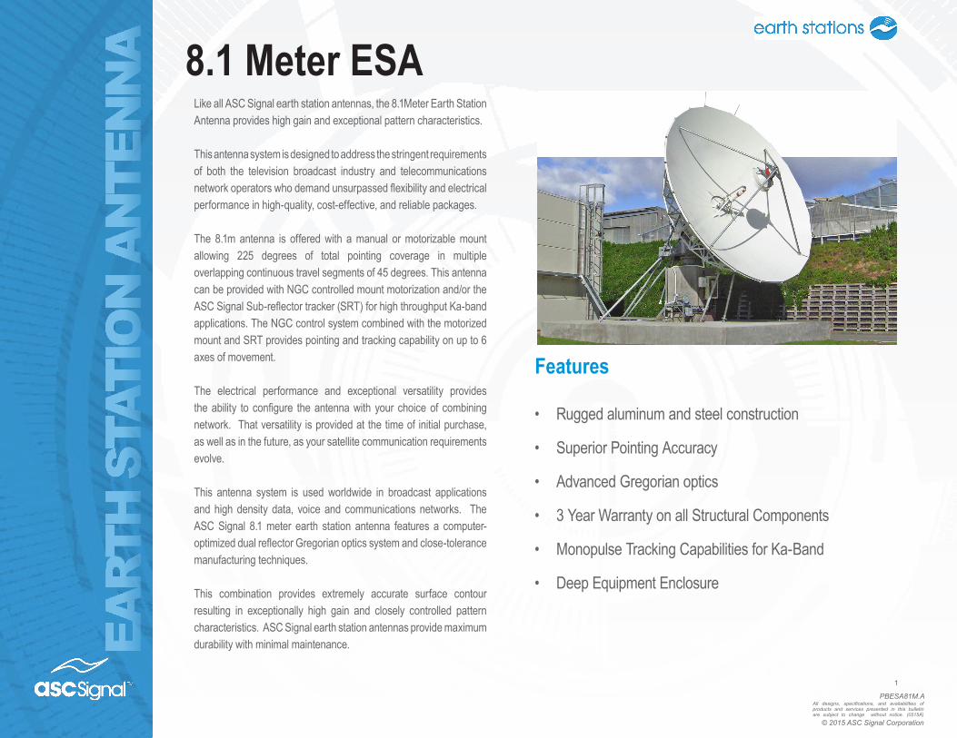
Like all ASC Signal earth station antennas, the 8.1Meter Earth Station Antenna provides high gain and exceptional pattern characteristics.
This antenna system is designed to address the stringent requirements of both the television broadcast industry and telecommunications network operators who demand unsurpassed flexibility and electrical performance in high-quality, cost-effective, and reliable packages.
The 8.1m antenna is offered with a manual or motorizable mount allowing 225 degrees of total pointing coverage in multiple overlapping continuous travel segments of 45 degrees. This antenna can be provided with NGC controlled mount motorization and/or the ASC Signal Sub-reflector tracker (SRT) for high throughput Ka-band applications. The NGC control system combined with the motorized mount and SRT provides pointing and tracking capability on up to 6 axes of movement.
The electrical performance and exceptional versatility provides the ability to configure the antenna with your choice of combining network. That versatility is provided at the time of initial purchase, as well as in the future, as your satellite communication requirements evolve.
This antenna system is used worldwide in broadcast applications and high density data, voice and communications networks. The ASC Signal 8.1 meter earth station antenna features a computer-optimized dual reflector Gregorian optics system and close-tolerance manufacturing techniques.
This combination provides extremely accurate surface contour resulting in exceptionally high gain and closely controlled pattern characteristics. ASC Signal earth station antennas provide maximum durability with minimal maintenance.
Features
• Rugged aluminum and steel construction
• Superior Pointing Accuracy
• Advanced Gregorian optics
• 3 Year Warranty on all Structural Components
• Monopulse Tracking Capabilities for Ka-Band
• Deep Equipment Enclosure
8.1 Meter ESA

EART
H S
TATI
ON
AN
TEN
NA
PBESA81M.A
2
All designs, specifications, and availabilities of products and services presented in this bulletin are subject to change without notice. (0515A)
© 2015 ASC Signal Corporation
The 8.1m Antenna mechanical general specifications and performances are listed in below table. Additional information, dimensions and layout may be provided by ASC Signal on a case-by-case basis.
Optics Type Dual Reflector Gregorian
Reflector Material Precision-Formed Aluminum
Reflector Segments 20
Mount Type El over Az, Pedestal Mount
Antenna Pointing Range, Coarse/(Continuous)Elevation: 0-90o (90o)
Azimuth: 225o (45o)
Polarization 180o (180o)
Hub/Enclosure DimensionsDiameter 2.14 m (84 in)
Depth 1.17 m (45 in)
Mechanical Performances
Reflector Aluminum painted with highly diffusive white paint
Ground Mount Hot-dipped galvanized steel, per ASTM-A123 for structural steel.
Hardware Sizes ≤ 3/8 in (9.5mm), stainless steel, passivated per MIL-F-14072-E300Sizes �≥ 3/8 in (9.5mm), hot-dipped galvanized stainless steel, passivated per ASTM-A123
Design Standards
Environmental Performances Operating Temperature -40o to 52oC (-40o to 125oF)
Seismic (Earthquake) 1 G Vertical and Horizontal acceleration. Equivalent to a Richter Magnitude 8.3, and Grade 11 on the modified Mercalli Scale
Operational Winds 45 mph (72 km/h) Gusts to 65 mph (105 km/h)
Survival Winds 125 mph (200 km/h) in any position of operation
Rain 4 in (102 mm) per hour
Solar Radiation 360 BTU/hr/ft2 (1135 Watts/m2)
Relative Humidity 100%
Shock and Vibration As encountered by commercial Air, Rail and Truck shipment.
Atmospheric Conditions As encountered by Moderately Corrosive Coastal and Industrial Areas.
Packing OptionsStandard Commercial Domestic Pack Included
Ocean Export Pack - For non-containerized, packed for seal against salt water spray
OCEANSHP-LG
Air Export Pack - For freighter aircraft shipments. Lower deck AirPack requires specialized bids
AIR EXPORT PACK-LG
Container Packaging CNTPCK-LG
Required Shipping ContainerStandard 20 ft land/sea container Quantity 1
Standard 40 ft land/sea container Quantity 1
Shipping Information
Shipping container information is given for basic configuration and may vary depending on the selected options, please contact ASC Signal for specific container loading plan.
8.1 Meter ESA
EART
H S
TATI
ON
AN
TEN
NA
PBESA81M.A
3
All designs, specifications, and availabilities of products and services presented in this bulletin are subject to change without notice. (0515A)
© 2015 ASC Signal Corporation
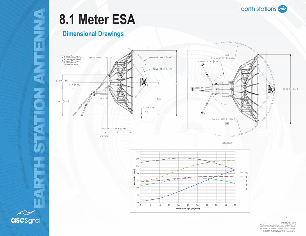
Dimensional Drawings
0
5
10
15
20
25
30
35
0 5 10 20 30 40 50 60 70 80 90
Dimen
sion
(feet)
Elevation Angle (degrees)
A
B
C
D
E
8.1 Meter ESA

EART
H S
TATI
ON
AN
TEN
NA
PBESA81M.A
4
All designs, specifications, and availabilities of products and services presented in this bulletin are subject to change without notice. (0515A)
© 2015 ASC Signal Corporation
Typical Foundation Design180 in 180 in
180 in.
36 in
180 in.
85.0
0in.
Soil Bearing Capacity, 2000 lb/ft2 (9770 kg/m2)
Reinforcing Steel, 3.7 tons (3400 kg)
Concrete Compressive Strength,
3000 psi (211 kg/cm2)
Foundation Size: (for specific standard soil and typical design)
Length 30 ft (9.14 m)
Width 30 ft (9.14 m)
Depth 3 ft (0.91 m) / 10ft (3.07 m)
Concrete Volume 107 yd3 (81.8 m3)
NOTE: Other typical foundation designs are available. Soil borings and foundation analysis should be performed by a qualified civil engineer.
Typical Foundation InformationNote: Crane access is to be
provided within 40ft (12m) of pads (based on 15 ton crane)
Assembly area for mount and antenna
30ft (9m) minimum clearance
on either side of foundationfor crane access
15ft (4.5m)
minimumclearance
2ft (0.6m)minimumclearance
15ft (4.5m)
minimumclearance
Azm = Azimuthdirection of mount
20ft (6m)minimumclearance
30ft (9m)
30ft (9m)
Foundation information are provided in bulletin 240445, please contact ASC Signal.
8.1 Meter ESA
EART
H S
TATI
ON
AN
TEN
NA
PBESA81M.A
5
All designs, specifications, and availabilities of products and services presented in this bulletin are subject to change without notice. (0515A)
© 2015 ASC Signal Corporation
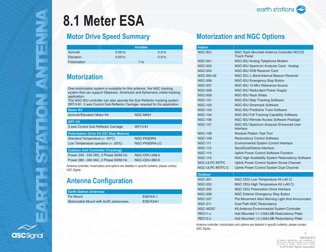
One motorization system is available for this antenna: the NGC tracking system that can support Steptrack, Smartrack and Ephemeris orbital tracking application.The NGC-IDU controller can also operate the Sub-Reflector tracking system SRT-3-81, 3 axis Control Sub-Reflector Carriage, required for Ka application.
Motor KitAzimuth/Elevation Motor Kit NGC-MK81
SRT Kit3 axis Control Sub-Reflector Carriage SRT-3-81
Polarization Drive Kit (DC Step Motors)Standard Temperature (> -20oC) NGC-PK9DRA
Low Temperature operation (< -20oC) NGC-PK9DRA-LO
Outdoor Unit Controller (Tracking)Power 200 - 230 VAC, 3 Phase 50/60 Hz NGC-ODU-208-5
Power 380 - 460 VAC, 3 Phase 50/60 Hz NGC-ODU-380-5
VariableAzimuth 0.05o/s 0.5o/s
Elevation 0.05o/s 0.5o/s
Polarization 1o/s
Motorization
Motor Drive Speed Summary
Earth Station AntennasFix Mount. ES81KA-1
Motorizable Mount with Az/El Jackscrews. ES81KAA1
Antenna Configuration
Antenna controller, motorization and options are detailed in specific bulletins, please contact ASC Signal..
IndoorNGC-IDU NGC Rack Mounted Antenna Controller W/LCD
Touch Panel
NGC-001 NGC-IDU Analog Telephone Modem
NGC-002 NGC-IDU Spectrum Analyzer Card - Analog
NGC-003 NGC-IDU DVB Receiver Card
NGC-004-02 NGC IDU, L-Band Internal Beacon Receiver
NGC-006 NGC-IDU Emergency Stop Button
NGC-007 NGC-IDU 10 Mhz Reference Source
NGC-008 NGC-IDU Redundant Power Supply
NGC-009 NGC-IDU Rack Slides
NGC-101 NGC-IDU Step Tracking Software
NGC-102 NGC-IDU Smartrack Software
NGC-103 NGC-IDU Predictive Track Software
NGC-104 NGC-IDU Full Tracking Capability Software
NGC-106 NGC-IDU Remote Access Software Package
NGC-107 NGC-IDU Spectrum Analyzer Enhanced User Interface
NGC-108 Receive Pattern Test Tool
NGC-109 Redundancy Control Software
NGC-111 Environmental System Control Interface
NGC-112 Sand/Dust/Debris Interface
NGC-115 Uplink Power Control Software Function
NGC-119 NGC High Availability System Redundancy Software
NGC-ULPC-INTFC Uplink Power Control System Sincle Channel
NGC-ULPC-INTFC-2 Uplink Power Control System Dual Channel
OutdoorNGC-201 NGC ODU Low Temperature Kit (-40 C)
NGC-202 NGC ODU High Temperature Kit (+60 C)
NGC-205 NGC ODU Polarization Drive Interface
NGC-206 NGC Exterior Emergency Stop Button
NGC-207 Pre Movement Alert Warning Light And Announcator
NGC-211 Dual Path NGC Redundancy
NGC-AESC Kit,Antenna Environmental System Controller
RED11-x Hub Mounted 1:1 LNA/LNB Redundancy Plate
RED12-x Hub Mounted 1:2 LNA/LNB Redundancy Plate
Motorization and NGC Options
Antenna controller, motorization and options are detailed in specific bulletins, please contact ASC Signal..
8.1 Meter ESA

EART
H S
TATI
ON
AN
TEN
NA
PBESA81M.A
6
All designs, specifications, and availabilities of products and services presented in this bulletin are subject to change without notice. (0515A)
© 2015 ASC Signal Corporation
X/KA- BAND FEED SYSTEMS
PORT CP LOW PIM RX 7.25 - 7.75 GHz
TX 7.9 - 8.4 GHz
RX 20.2 - 21.2 GHz
TX 30.0 - 31.0 GHz
8CPXKA-81-1 8 X X X X X
6CPXKA-81-1-LP 6 X X X X X X
8CPXKA-81-1-LP 8 X X X X X X
Feed Matrix
For Monopulse application, please contact ASC Signal.
Ka- BAND FEED SYSTEMS
PORT CP LP RX 17.7 - 21.2 GHz
TX 27.5 - 31.0 GHz
RX 21.4 - 22.0 GHz
RX 27.0 - 30.05 GHz
4CPWWKA-81-206 4 X X X
4LPWWKA-81 4 X X X
4LPEUTKA-8 4 X X X
For redundant application, LNA support kits are available for each of the above feeds. Please contact ASC Signal.
8.1 Meter ESA
EART
H S
TATI
ON
AN
TEN
NA
PBESA81M.A
7
All designs, specifications, and availabilities of products and services presented in this bulletin are subject to change without notice. (0515A)
© 2015 ASC Signal Corporation
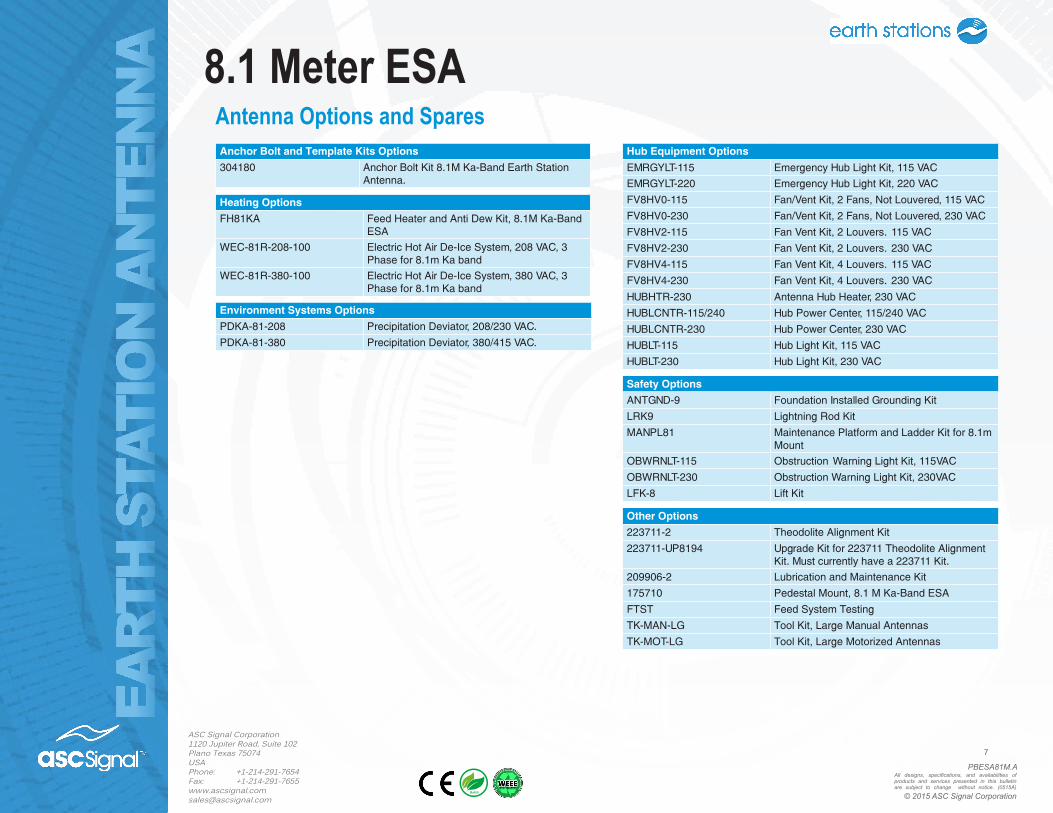
Anchor Bolt and Template Kits Options
304180 Anchor Bolt Kit 8.1M Ka-Band Earth Station Antenna.
Heating Options
FH81KA Feed Heater and Anti Dew Kit, 8.1M Ka-Band ESA
WEC-81R-208-100 Electric Hot Air De-Ice System, 208 VAC, 3 Phase for 8.1m Ka band
WEC-81R-380-100 Electric Hot Air De-Ice System, 380 VAC, 3 Phase for 8.1m Ka band
Environment Systems Options
PDKA-81-208 Precipitation Deviator, 208/230 VAC.
PDKA-81-380 Precipitation Deviator, 380/415 VAC.
Hub Equipment Options
EMRGYLT-115 Emergency Hub Light Kit, 115 VAC
EMRGYLT-220 Emergency Hub Light Kit, 220 VAC
FV8HV0-115 Fan/Vent Kit, 2 Fans, Not Louvered, 115 VAC
FV8HV0-230 Fan/Vent Kit, 2 Fans, Not Louvered, 230 VAC
FV8HV2-115 Fan Vent Kit, 2 Louvers. 115 VAC
FV8HV2-230 Fan Vent Kit, 2 Louvers. 230 VAC
FV8HV4-115 Fan Vent Kit, 4 Louvers. 115 VAC
FV8HV4-230 Fan Vent Kit, 4 Louvers. 230 VAC
HUBHTR-230 Antenna Hub Heater, 230 VAC
HUBLCNTR-115/240 Hub Power Center, 115/240 VAC
HUBLCNTR-230 Hub Power Center, 230 VAC
HUBLT-115 Hub Light Kit, 115 VAC
HUBLT-230 Hub Light Kit, 230 VAC
Safety Options
ANTGND-9 Foundation Installed Grounding Kit
LRK9 Lightning Rod Kit
MANPL81 Maintenance Platform and Ladder Kit for 8.1m Mount
OBWRNLT-115 Obstruction Warning Light Kit, 115VAC
OBWRNLT-230 Obstruction Warning Light Kit, 230VAC
LFK-8 Lift Kit
Other Options
223711-2 Theodolite Alignment Kit
223711-UP8194 Upgrade Kit for 223711 Theodolite Alignment Kit. Must currently have a 223711 Kit.
209906-2 Lubrication and Maintenance Kit
175710 Pedestal Mount, 8.1 M Ka-Band ESA
FTST Feed System Testing
TK-MAN-LG Tool Kit, Large Manual Antennas
TK-MOT-LG Tool Kit, Large Motorized Antennas
Antenna Options and Spares
ASC Signal Corporation1120 Jupiter Road, Suite 102Plano Texas 75074USAPhone: +1-214-291-7654Fax: [email protected]
8.1 Meter ESA