By VINU FOOD PRODUCTS 15-11-20111A Presentation by VINU FOOD PRODUCTS.
Upload
duongtuyenCategory
view
214download
0
POUR L'OBTENTION DU GRADE DE DOCTEUR ÈS SCIENCES
acceptée sur proposition du jury:
Prof. P.-A. Farine, président du juryProf. H. Shea, S. Rosset, directeurs de thèse
Prof. F. Carpi, rapporteur Prof. I. Graz, rapporteur
Prof. Ph. Renaud, rapporteur
Arrays of dielectric elastomer microactuators for cell mechanotransduction
THÈSE NO 5697 (2013)
ÉCOLE POLYTECHNIQUE FÉDÉRALE DE LAUSANNE
PRÉSENTÉE LE 6 JUIN 2013
À LA FACULTÉ DES SCIENCES ET TECHNIQUES DE L'INGÉNIEURLABORATOIRE DES MICROSYSTÈMES POUR LES TECHNOLOGIES SPATIALES
PROGRAMME DOCTORAL EN MICROSYSTÈMES ET MICROÉLECTRONIQUE
Suisse2013
PAR
Samin AkBARI


iii
Abstract
Understanding how the cells modulate their behavior in response to the mechanical stress present
in their organism can potentially lead to new therapeutic strategies for several diseases such as
muscle dystrophy, osteoporosis or reversing age-related cellular degeneration. Exactly how the
cell is able to decipher the mechanical stress and evoke distinct responses is poorly understood
and requires the development of high precision actuators capable of stretching either isolated
cells, or small colonies of cells. In this thesis, a new concept for precise and high throughput cell
stretching by integrating dielectric elastomer microactuators (µDEAs) in the cell culture
substrate is introduced and developed. Two generations of µDEA arrays are developed; the first
generation consists of an array of 72 100 µm x 200 µm actuators generating up to 5 % uniaxial
strain with response time of 0.2 s when a voltage is applied. The accurate strain measurement is
accomplished by tracking displacement of an array of 4 µm diameter Al dots. The actuation
strain in this generation is suitable for stimulation of cells from stiff tissues such as bone cells.
100 µm x 100 µm dielectric elastomer actuators in the second generation exhibit up to 37% in-
plane actuation strain amply sufficient to stimulate any cell type with relevant biological strain.
The cells are chemically attached to the polymeric actuators following a functionalizing step and
stretched together with the actuators when 4.2 kV is applied at 1 Hz for four hours proving that
the device is well compatible with the biological experiments.
The conceptual design, modeling, fabrication and characterization of dielectric elastomer
microactuators are presented. The actuators are miniaturized as small as 100 x 100 µm2 with
actuation strain of up to 80%. Theoretical guidelines for enhanced actuation strain of silicone
based dielectric elastomer actuators are developed by taking into account the hyperelastic
behavior of the dielectric elastomers.
Keywords: dielectric elastomer actuator, microactuators, low energy ion-implantation, cell
stretcher, high throughput, theoretical analysis

iv
Résumé
Comprendre comment les cellules modulent leur comportement en réponse aux contraintes
mécaniques dans leur organisme peut potentiellement conduire à de nouvelles stratégies
thérapeutiques pour plusieurs maladies telles que la dystrophie musculaire, l'ostéoporose ou
conduire à l'inversion de la dégénérescence cellulaire liée à l’âge. Le processus à travers duquel
la cellule est capable de déchiffrer les contraintes mécaniques et de provoquer des réactions
distinctes est mal compris et nécessite le développement d'actionneurs de haute précision
capables d'étirement de cellules isolées ou de petites colonies de cellules. Dans cette thèse, un
nouveau concept d’actionneur pour étirer des cellules basé sur les micro-actionneurs en
polymère (dielectric elastomer microactuators, μDEAs) est introduit et développé. Deux
générations de matrices de μDEA sont développées; la première génération est constituée d'une
matrice de 72 100 µm x 200 µm actionneurs générant jusqu'à 5% de contrainte uniaxiale avec un
temps de réponse de 0,2 s lorsqu'un voltage est appliqué. La mesure de déformation précise est
réalisée par l’observation du déplacement d'un réseau de micro-points de 4 µm de diamètre en
aluminium. La déformation de cette génération d’actionneurs est adaptée à la stimulation des
cellules provenant de tissus rigides tels que des cellules osseuses. La seconde génération, formée
par des actionneurs en polymère de 100 µm x 100 µm présentent jusqu'à 37% de déformation
dans le plan, ce qui est amplement suffisant pour stimuler tout type de cellules. Les cellules sont
liées chimiquement aux actionneurs en polymère après une étape de fonctionnalisation et étirées
en même temps que les actionneurs lorsque 4.2 kV sont appliqués à 1 Hz pendant quatre heures,
prouvant que le dispositif est bien compatible avec les expériences biologiques.
La conception, la modélisation, la fabrication et la caractérisation de micro-actionneurs
élastomères diélectriques sont présentées. Les actionneurs sont miniaturisés aussi petit que 100 x
100 μm2 pour une déformation jusqu'à 80%. Des règles théoriques pour l’optimisation de la
déformation des actionneurs en polymère dielectrique sont développées en tenant compte du
comportement hyperélastique des élastomères diélectriques.
Mots-clés: actionneur élastomère diélectrique, microactionneurs, implantation ionique à faible
énergie, civière portable, haut débit, analyse théorique.

v
Acknowledgment
I would like to thank my professor, Prof. Herbert Shea, who gave me the opportunity to join his
lab and patiently supervised me until I became an experimentalist. His clever scientific advice
and consistent encouragement was a great help in the first years of PhD as the most frustrating
period when the device was not working. I am indebted to his continued support and unlimited
trust at the last year of PhD when he let me leave for a six months sabbatical to Harvard
University. I also would like to thank Dr. Samuel Rosset, my co-advisor for his helpful scientific
advice and carefully commenting on my thesis.
I am deeply thankful to the members of my Jury, Prof. Federico Carpi, Prof. Ingrid Graz, and
Prof. Philippe Renaud who have honored me by accepting to review and evaluate this thesis and
Prof. Pierre-André Farine for accepting to be the president of the jury.
I thank Dr. Muhamed Niklaus who trained me in the first months on the equipment in the lab and
also Dr. Andres Punning from whom I learned to never give up trying a new idea. I also thank
Dr. Caglar Ataman, Dr. Sebastien Lani, Dr. Yve Petremond, and Dr. Kustav Ghose who gave me
time and the benefit of their expertise in training me to use the cleanroom equipment. Thanks to
Dr. Peter Van der Wal, Edith Millotte, Claudio Novelli, and Sylviane Pochon for their help and
comments.
Many thanks to Dr. Massoud Dadras from the microscopy and nanoscopy center of CSEM for
his significant help in EDS measurement of ion-implanted samples. Besides his scientific
contribution to this thesis, I appreciate his work and life related advice during these 4 years.
I would like to thank Dr. Oscar Vazquez Mena a former PhD student at LMIS1 lab at EPFL who
kindly fabricated the nanostencils for deposition of the dots on the actuators.
I would like to thank Dr. Alfredo Obregon our biologist collaborator from space biology group at
ETH-z for his helpful advice on the cell biology. I also thank Mr. Krzysztof Krawczyk who
performed the biological experiments and took care of the cell growth on the device.
I also thank my friends and lab mates Luc, Jun, Simon, Sara, Alexandre, Seun, Subha, Pille,
Mohssen, Joanna, Dara, and Vinu for their help in the lab and the nice time we spent together. I
also greatly appreciate the help from Myriam Poliero and Marie Halm during the years at LMTS.

vi
My deepest thanks to my family specially my parents for their endless love and support and their
belief in me. Many thanks to all you did for educating me. You are the main reason of who I am
today.
Lastly and most importantly, I thank my husband, Tohid, who has been a great source of support.
Thanks for your sacrifice, for your listening, for your encouraging words, for all the time you
spent on proof-reading my articles and for the continuous joy and love that you bring to my life.

vii
Contents
Chapter 1 Introduction ............................................................................................................... 1
1.1. Background and motivation ............................................................................................. 1
1.2. Research objective ............................................................................................................ 2
1.3. Thesis outline and contributions ...................................................................................... 4
Chapter 2 State of the Art (1): In-vitro mechanical stimulation of cells ................................... 6
2.1. Summary .......................................................................................................................... 6
2.2. In-vitro mechanical stimulation of cells ........................................................................... 6
2.3. Conclusion ........................................................................................................................ 9
Chapter 3 State of the Art (2): Dielectric elastomer actuators ................................................ 10
3.1. Summary ........................................................................................................................ 10
3.2. Actuation principle ......................................................................................................... 10
3.3. Polymers for DEAs ........................................................................................................ 12
3.4. DEA-based devices ........................................................................................................ 14
3.5. Miniaturization of compliant electrodes for DEAs ........................................................ 17
3.6. Conclusion ...................................................................................................................... 20
Chapter 4 Theoretical analysis of dielectric elastomer actuators with experimental validations
21
4.1. Summary ........................................................................................................................ 21
4.2. Introduction .................................................................................................................... 22
4.3. Theoretical formulations ................................................................................................ 22
4.3.1. Small actuation strain .............................................................................................. 23
4.3.2. Material modeling ................................................................................................... 24
4.3.3. Governing equations of DEAs ................................................................................ 27

viii
4.4. Biaxial prestretch ............................................................................................................ 28
4.5. Uniaxial prestretch ......................................................................................................... 32
4.6. Optimum prestretch conditions ...................................................................................... 34
4.7. Experimental verifications ............................................................................................. 35
4.8. Miniaturization of the actuators ..................................................................................... 38
4.9. Conclusion ...................................................................................................................... 39
Chapter 5 Compliant electrodes by low energy ion-implantation ........................................... 41
5.1. Summary ........................................................................................................................ 41
5.2. Introduction .................................................................................................................... 41
5.3. Homogenous electrodes in the scanning mode .............................................................. 43
5.4. Miniaturized ion-implanted compliant electrodes .......................................................... 46
5.5. Energy of ion-implantation ............................................................................................ 48
5.6. Conclusion ...................................................................................................................... 50
Chapter 6 Generation I: Small deformation µDEAs ............................................................... 51
6.1. Summary ........................................................................................................................ 51
6.2. Actuation principle ......................................................................................................... 52
6.3. Design considerations .................................................................................................... 53
6.4. Finite Element Analysis ................................................................................................. 54
6.5. Microfabrication ............................................................................................................. 57
6.5.1. Fabrication of Pyrex chips with patterned gold electrodes and etched channels .... 59
6.5.2. Fabrication of 30 m thick PDMS membrane ........................................................ 60
6.5.3. Compliant electrodes by low energy ion-implantation ........................................... 60
6.5.4. Bonding ................................................................................................................... 61
6.6. Characterization ............................................................................................................. 62

ix
6.6.1. Image processing .................................................................................................... 64
6.6.2. Static response ........................................................................................................ 66
6.6.3. Dynamic response ................................................................................................... 71
6.6.4. Life time measurement ........................................................................................... 73
6.6.5. Direct bonding ........................................................................................................ 74
6.7. Conclusion ...................................................................................................................... 77
Chapter 7 Generation II: Large deformation µDEAs .............................................................. 79
7.1. Summary ........................................................................................................................ 79
7.2. Actuation principle ......................................................................................................... 80
7.3. Fabrication ...................................................................................................................... 83
7.3.1. Fabrication of single-layer actuators ....................................................................... 83
7.3.2. Fabrication of double-layer actuators ..................................................................... 84
7.4. Characterization ............................................................................................................. 84
7.4.1. Characterization of single-layer actuators .............................................................. 85
7.4.2. Characterization of double-layer actuators ............................................................. 89
7.4.3. Dynamic response ................................................................................................... 91
7.5. Conclusion ...................................................................................................................... 92
Chapter 8 DEA based cell stretcher ......................................................................................... 93
8.1. Summary ........................................................................................................................ 93
8.2. biocompatibility of elastomers ....................................................................................... 93
8.3. Electric field elimination ................................................................................................ 95
8.4. Device fabrication .......................................................................................................... 96
8.5. Operating in conductive liquid ..................................................................................... 101
8.6. Biological experiment .................................................................................................. 104

x
8.7. Conclusion .................................................................................................................... 107
Chapter 9 Conclusions ........................................................................................................... 108
9.1. Summary ...................................................................................................................... 108
9.2. Main achievements ....................................................................................................... 108
9.3. Future outlooks ............................................................................................................. 111
List of publications ..................................................................................................................... 113
Appendix: Internship at Harvard University ............................................................................... 115
Cell-encapsulation in Alginate microparticles ........................................................................ 115
High throughput screening of target-specific secreting cells .................................................. 117
References ................................................................................................................................... 118
Curriculum Vitae ........................................................................................................................ 128

Chapter 1 Introduction
1.1. Background and motivation
Biological cells proliferate, differentiate, migrate, or express genes in response to mechanical
stress present in their organism [1-4]. The mechanical stress can originate from several sources
such as: gravity, compression forces within joints, and dynamic mechanical stimulation resulting
from muscular activity, which is often periodic such as heartbeat and breathing. Extracellular
forces are transduced across the cell membrane and regulate the intracellular biochemical events
so called mechanotransduction. Indeed, most cells utilize some form of mechanotransduction for
their survival.
Due to the complexity of in vivo environment, the systematic study of the cell
mechanotransduction is currently performed, in vitro, with simple membrane cell-stretching
equipment with limited capabilities, relying on the deformation of a flexible membrane by
vacuum or a mechanical motor. Uniaxial, biaxial, radial or circumferential strain can be applied,
with strain of up to 20% at frequencies in order of 1 Hz, but the areas stretched are often in the
range of centimeters, much too large to monitor single-cell responses; instead investigators often
measure the averaged response of hundreds of thousands of cells that, by synchronizing their
communal behavior, make it very difficult to analyze the first stages of cell differentiation (more
detailed information in Chapter 2).
To precisely understand how the cell is able to decipher mechanical stimuli to evoke distinct
responses, high precision actuators capable of stretching either isolated cells, or small colonies of

Chapter 1 Introduction 2
cells are required. Arrays of these actuators grouped into subsections will allow study of various
strain levels at a single experiment, eliminating any variation encountered in performing multiple
studies over several days.
Dielectric elastomer actuators (DEAs) as flexible polymers expanding in response to electrical
stimuli show a great promise in development of deformable cell culture systems. DEAs are a fast
growing class of electroactive polymer actuators commonly referred to as artificial muscles due
to their similar properties to natural muscle. They combine large actuation strain, fast response
and high energy density and are therefore, potentially capable of deforming the cells with
relevant mechanical strains and frequencies. Using biocompatible elastomers as the dielectric
elastomer in the actuator and also as the flexible membrane in the cell culture system simplifies
integration of the actuators with the cell stretching device. Developing arrays of dielectric
elastomer microactuators integrated in the cell culture substrate enables mechanically deforming
groups of isolated cells with various and precise strain levels in the same experiment, allowing
high throughput analysis.
1.2. Research objective
The main objective of this thesis is to develop arrays of dielectric elastomer microactuators to
stretch isolated cells with a high throughput at relevant biological strains and frequencies. The
cell stretching device consists of integrated microactuators in the cell culture substrate that will
expand when a voltage is applied. The cells will adhere to the actuators and stretch together with
them, as shown schematically in Figure 1-1. The actuation strain is adjustable with the applied
voltage enabling mechanical stimulation of the cells with various strain levels or frequencies at
the same experiment and therefore, allowing high throughput analysis of mechanotransduction.

3 1.2. Research objective
Figure 1-1- Schematic of high throughput cell stretching device; Arrays of integrated microactuators expand in response to the applied voltage and stretch the adhered cells. Deflection of each actuator and thus, the strain applied to the attached cell is tunable with the applied voltage and can vary from 0 to 20% in a single experiment.
The developed dielectric elastomer actuators (DEAs) should meet the following requirements to
be successfully implemented for cell stretching applications:
The actuation strain of the actuators should be adjustable between 1% and 20% to mimic the
in-vivo conditions of most of the cell types. 1% strain is sufficient for stimulation of stiff cells
such as bone cells and up to 20% strain can be applied to study the mechanotransduction of
muscle cells [1-3].
The actuators should be miniaturized to stretch individual cells or small colonies of cells
providing more in depth insight on the mechanotransduction of single cells.
Precise and uniform strain should be generated by the actuators.
The actuators should be biocompatible.
The device should operate in cell growth environment exposed to conductive cell growth
medium.
The device should be compatible with conventional equipment used by biologists such as the
inverted microscopes or the incubators (temperature and humidity level) allowing long term
stimulation.

Chapter 1 Introduction 4
1.3. Thesis outline and contributions
The main contribution of this thesis is developing arrays of dielectric elastomer microactuators
for high throughput cell stretching application. The thesis focuses on the conceptual design,
theoretical or finite element analysis, fabrication and characterization of the actuators.
Chapter 2: The literature on the in-vitro systems to deform the cells as a tool to study the
mecahnotransuction is briefly reviewed.
Chapter 3: Dielectric elastomer actuators and their actuation principle are introduced. The main
components of DEAs, which are the polymers and the compliant electrodes are reviewed with
focus on miniaturized actuators.
Chapter 4: Theoretical analysis of dielectric elastomer actuators considering the nonlinear
stress-strain correlation of the elastomers is explained in detail. It is clarified that the existing
theoretical guidelines in the literature developed based on premade commercially available films
cannot be directly implemented to silicone based elastomers. The effect of different prestretch
modes and choice of the elastomer in performance of the DEAs is also discussed. The theoretical
calculations are verified with experimental results and it is demonstrated that miniaturization of
the actuators enhances the actuation strain by pushing back the loss of tension failure mode.
Chapter 5: The operation principle of low energy ion-implantation is briefly discussed as it is
the main technique used to pattern the microelectrodes for the developed cell stretching devices.
It is addressed how to pattern uniform microelectrodes as small as 100 µm on PDMS membranes
with minimized stiffening impact.
Chapter 6: Conceptual design, fabrication and characterization of the first generation of
dielectric elastomer microactuators are discussed. The device consists of arrays of 100 µm x 200
µm actuators on non-stretched PDMS membrane bonded on a Pyrex chip with patterned
trenches. The performance of the actuators is predicted with finite element analysis, which is
then validated with experimental results. Actuation strain of up to 5% is achieved with response
time of 0.2 s allowing stimulation of the cells from stiff tissues with relevant biological strain
and frequencies.

5 1.3. Thesis outline and contributions
Chapter 7: In the second generation of dielectric elastomer microactuators, the actuation strain
is enhanced up to 80% by taking advantage of the hyperelasticity of the elastomers. The
elastomer is uniaxially prestretched 2.75 times its initial length and then two perpendicular arrays
of electrodes are patterned on top and bottom layer of the elastomer. The elastomer has stiffened
in the prestretched direction allowing large deformation in the transverse direction. To avoid
short circuiting the top electrodes with the conductive cell growth medium and allow longer life
time, a 25 µm thick passive PDMS layer is bonded on the elastomer. The actuation strain of the
array of double layer dielectric elastomer actuator suitable for cell stretching application is
adjustable with the applied voltage up to 37%.
Chapter 8: The basic concept of the second generation is further developed to use the device as
a cell stretcher. The biocompatibility of the elastomers used in fabrication is verified and
myoblast cell types are cultured on the device and stretched at 4.2 kVs and 1 Hz for 4 hours.
Chapter 9: The future outlooks and the concluding remarks of the thesis are presented.
Chapter 2 State of the Art (1): In-vitro mechanical
stimulation of cells
2.1. Summary
In this chapter, the in-vitro techniques for mechanotransduction studies are briefly reviewed and
the major efforts towards developing a high throughput cell stretcher are discussed.
2.2. In-vitro mechanical stimulation of cells
It is now clear that the extracellular forces are transduced across the membrane regulating the
intracellular biochemical events and subsequently cell proliferation, differentiation, or gene
expression. Systematic study of cell mechanotransduction is typically relied on deforming the
cells, in vitro, with different approaches as reviewed in Figure 2-1 [5, 6]. Traditionally to study
the mechanical properties of a cell, pipettes with internal diameters of 1-5 µm is used and the cell
is deformed into the pipette by applying a negative pressure, as shown in Figure 2-1(a) [6-8].
Optical traps or laser tweezers have also been extensively used to deform and manipulate a
single cell. Functionalized microbeads are attached to a cell; normally one of them is attached to
a wall and the other one is moved using a laser beam (Figure 2-1(b)). The force applied to the
beads by the cell is proportional to the required laser power to constrain the beads [9-11]. Using
an atomic force microscopy it is possible to locally deform the cell and calibrate the applied
force by measuring deflection of the flexible cantilever beam (Figure 2-1(c)) [12, 13]. Magnetic

7 2.2. In-vitro mechanical stimulation of cells
twisting cytometry is also used to locally deform the cell with magnetic beads twisted by a
magnetic field (Figure 2-1(d)) [14, 15].
The above mentioned techniques have a very low throughput meaning that only a single cell can
be characterized in one experiment. Therefore, they are mostly used to characterize the
mechanical properties of single cells such as their elasticity and viscosity.
Figure 2-1- Various approaches to deform the cells to study the mechanobiology: (a) A cell is deformed inside a micropippette with a diameter between 1-5 µm by applying a negative pressure. (b) A single cell is attached between two functionalized microbeads, one attached to a glass plate and the other one is confined by a laser. (c) The cell is deformed with an AFM, in which the force applied to the cell is caliberated by measuring deformation of the cantilever beam. (d) Funtionalized magnetic microbeads are attached to a cell and are twisted by a magnet to deform the cell. (e) The cell is deformed due to the shear stress from the fluid which passes over it. (f) The cell is attached to a flexible substrate which is stretched by mechanial force [6].
Another platform to study the mechanotransduction is to stimulate the cells with shear stress
while a fluid is flowing over it, as shown in Figure 2-1(e). It has been shown that shear stress
modulates the response of several cell types such as bone cells, neutrophils and bacteria [16-18].
It also plays an important role in differentiation of stem cells to vascular endothelial cells [19].
The shear force is conventionally applied using a parallel plate flow channels or cone and plate
rotating chambers. Due to low Reynolds number and laminar flows in microscale channels,
microfluidic devices have been used to apply a wide range of shear stress to the cells and study
the cell alignment or cell adhesion [20-22].

Chapter 2 State of the Art (1): In-vitro mechanical stimulation of cells 8
Recently, Gosset et al. have developed a microfluidic device, in which suspended cells flow
toward a junction and are stretched with extensional flow streams at high strains for a few
microseconds (Figure 2-2). Based on the deformability of the cells, they could predict the disease
state of patients with cancer and immune activation with sensitivity of 91% [23].
Figure 2-2- (a) Schematic of the deformation of a cell delivered to the center of an extensional flow. (b) High-speed microscopic images showing a focused cell entering the extensional flow region. Delivery and stretching occurs in less than 30 μs (Scale bar: 40 μm) [23].
The other approach to stimulate the cells with mechanical stress is to stretch the substrate over
which they are cultured, as shown in Figure 2-1(f). It can better mimic the in-vivo environment
of adherent cells. Varieties of stretchable cell culture substrate systems have been developed
reviewed by Brown [24]. The majority of devices consists of a flexible membrane distended by
vacuum (e.g., those made by Flexcell Inc, Hillsborough, NC, USA [25]) or stretched using a
mechanical motor (e.g. Strex from B-Bridge International Inc, USA [26]). Employing the above
mentioned devices, strain of up to 20% at frequencies of order 1 Hz is achievable, but the areas
stretched are often in the range of centimeters, much too large to monitor single-cell responses;
instead investigators often measure the averaged response of hundreds of thousands of cells that,
by synchronizing their communal behavior, make it very difficult to analyze the first stages of
cell differentiation. Moreover, it is difficult to fit these large devices in the traditionally used
incubators or observe the cells while stretched under the conventional microscopes, since they
are large or are connected to large accessories such as a pump or a motor.
Recently, there is more research going on by different groups to develop new cell stretching
devices that can overcome the current limitations of conventional cell stretchers. There are a few
Microelectromechanical systems (MEMS) developed to apply calibrated strain level to single

9 2.3. Conclusion
cells. Sarrel et al. developed a uniaxial cell stretcher made of two silicon plates connected to two
sets of electrostatic microactuators [27, 28]. A cell is cultured on the plates and stretched while
the plates are moving apart from each other. A biaxial cell stretcher with the same principle has
been developed by Scour et al. [29]. The drawback of these devices is their low throughput as
they can only stretch one cell in one experiment. Multiple experiments over several days are
required to test the effect of various strain levels or strain rates on multiple cells that leads to
unconfident results. Refer to the reviews written on microengineered systems for cell biology for
more details [5, 6, 30-32].
Array of miniaturized actuators have been developed to increase the throughput of the
experiments. Kamotani et al. used piezoelectrically actuated Braille display to apply strain to an
array of 24 chambers, each 1.7 mm in diameter [33]. Different groups have developed
microfabricated pneumatically actuated chambers to deflect the membrane upward or downward
with air flow [34-36]. Throughput of the system can be increased either by actuating with
different pressure or changing the geometry of the chambers. However, the deformation of a
bulged membrane is not uniform; tensile in the center and compressive at the rim. Down-scaling
these actuators to single cell level is feasible by microfabrication techniques but does not lead to
uniform and calibrated strain levels to the cell. Moraes et al. used the same bulged actuators to
compress the cells encapsulated in hydrogel above the actuators [37]. Simmons et al. developed
array of millimeter sized actuators, in which a thin biocompatible polymer is stretched under
vacuum over an acrylic post, creating a consistent strain field across each post and thus
stretching the attached biological sample. In this configuration, the biological sample stays in the
same focal plane and the cells experience a uniform strain level [38]. Nevertheless, these
actuators are still mm2 area much too large to monitor the single cell response.
2.3. Conclusion
In conclusion, a high throughput single cell stretcher device capable of applying precise and
uniform strain levels to the adherent cells is not yet developed and is the main objective of this
thesis. This objective is delivered employing dielectric elastomer actuators to deform the cell
culture substrate. The actuation principle and the impact of their main components, which are the
polymers and the compliant electrodes, on their performance are reviewed in the next chapter.
Chapter 3 State of the Art (2): Dielectric elastomer
actuators
3.1. Summary
Dielectric elastomer actuators (DEAs) are an emerging class of polymer-based actuators,
combining large strains, high energy density and fast response time [39, 40]. In this chapter, I
will explain the actuation principle of this class of actuators and point out the polymers suitable
for actuation. The basic configurations for the DEAs and the major developed devices up to now
are briefly reviewed. Finally, I will focus on the techniques to pattern µm to mm-sized compliant
electrodes to miniaturize the DEAs
3.2. Actuation principle
DEAs consist of a thin elastomeric membrane sandwiched between two compliant electrodes.
When a voltage is applied between the electrodes, the electrostatic pressure squeezes the
elastomer between the electrodes. Since the elastomer is incompressible, it expands in the in-
plane directions (Figure 3-1).

11 3.2. Actuation principle
Figure 3-1-Schematic of a dielectric elastomer actuator; a) A membrane is of initial dimensions of 1 and ti
in thickness. Compliant electrodes are patterned on both sides of the membrane. b) A voltage is applied to the electrodes leading to planar expansion and thickness reduction.
The electrostatic pressure on the elastomer because of the applied voltage is equal to [41]
2f
2
t
VP (1)
Where, V is the applied voltage, tf is the final thickness, and ε is the permittivity of the
elastomer. The permittivity is typically considered constant and independent of the polymer
chain deformation [42]. Equalizing the electrostatic pressure with the stress in the thickness
direction (z direction) and assuming a linear correlation between stress and strain, which is valid
for strains of less than 10% on a non-prestretched elastomer, the strain in z direction is
2f
2
zt
V
YS
(2)
where, Y is the Young’s modulus of the elastomer.
Substituting tf with ti (1+Sz), the strain in z direction can be calculated from the following
equation as a function of voltage
2i
2z
2
zt)S1(
V
YS
(3)
In the case of free boundary conditions, strain in x and y directions are equal and dependent on
the strain in z direction due to the incompressibility of the elastomer
1)S1)(S1)(1S( yxz (4)
Chapter 3 State of the Art (2): Dielectric elastomer actuators 12
When the actuation strain of the dielectric elastomer actuator is larger than 20% or if the
elastomer is prestretched before actuation, the correlation between stress and strain is nonlinear
and the above mentioned formulations based on small deformation assumption are erroneous. I
will discuss the general and precise theoretical formulation of dielectric elastomer actuators in
detail in Chapter 4. However, the simplified strain-voltage relation in equation (2) or (3) gives a
good insight on the important parameters influencing the actuation strain. It is clear that using a
polymer with higher relative permittivity and lower Young’s modulus decreases the required
actuation voltage to achieve a desired actuation strain. In the next section, I will review the
commercially available polymers used to make dielectric elastomer actuators and point out the
efforts to synthesize the ideal polymer.
3.3. Polymers for DEAs
Several groups of polymers have been investigated for dielectric elastomer actuators. Acrylics,
silicones (including fluorinated silicones), polyurethanes, fluoroelastomers, ethylene–propylene
rubber (EPR), polybutadiene (PB) and polyisoprene (PI, natural rubber) are among them [43,
44]. VHB acrylics are the commercially available adhesive films supplied by 3M that show
exceptional actuation performance [45]. The highest actuation strains reported up to now are
based on this polymer [40, 46-48]. However, the exact formulation of this adhesive is not
revealed and the films are available at predefined thicknesses, which limits the independent
choice of the prestretch ratio and the film thickness. Moreover, VHB is highly viscoelastic and
shows frequency-dependent material properties, inhibiting its use for fast and reliable actuation
[49].
Silicone-based elastomers are the second main category of dielectric elastomers used for
dielectric elastomer actuator. They show a much faster response time as low as a few
milliseconds [50, 51]. They exhibit negligible viscoelastic behavior and high operating
temperatures. Silicones are generally available as a un-polymerized viscous liquid allowing to
make membranes of any desired thickness and thus, selecting the prestretch in the membrane,
independently. However, they exhibit smaller strain capabilities, and VHB is often preferred for
making impressive demonstrator in the labs.

13 3.3. Polymers for DEAs
Polyurethanes are the 3rd category of elastomer showing a promising potential for DEAs as they
generally have higher dielectric constant compared to acrylics and silicones and can be casted at
any desired thickness like silicones. Different types of this material is studied by Bayer company
[52] for their potential application in DEAs (unpublished). This material is used by Artificial
Muscle INC to produce vibrating actuators for games [53].
There has been a large effort by numerous researchers to synthesize the optimum elastomer for
dielectric elastomer actuators. For actuation strain of less than 20%, from equation (2), it is clear
that using a polymer with a higher relative permittivity and lower Young’s modulus decreases
the required actuation voltage to achieve a desired actuation strain and allows higher actuation
strain before the electrical breakdown or pull-in instability. One approach to increase the
dielectric constant of the elastomer is to use high permittivity filler particles. Conductive fillers
such as Nickel [54], carbon black [55], and carbon nanotubes [56] have resulted in improvement
in dielectric constant. However, adding conductive fillers leads to decreased electrical
breakdown strength and increased leakage earlier than the percolation mostly due to aggregation
of the particles. Using insulating high permittivity fillers prevent early short circuit in the
material by the aggregated particles. Insulating particles such as encapsulated polyaniline
particles [57], self passivated aluminum nanoparticles naturally coated with a thin layer of
insulating aluminum oxide on the surface [58], and surface-modified Titanium oxide
nanoparticles [59] have been reported to successfully enhance the dielectric permittivity.
Though, adding the fillers has a cross-effect on the mechanical properties and break-down
strength of the composite elastomer making it more complicated to enhance the actuation strain
at the end. It should also be mentioned that the formulation in equation (4) is for strain levels of
lower than 20% for which the linear correlation between stress and strain, is still valid and a
Young’s modulus can be defined. To achieve actuation strain of more than 26%, the pull-in
instability has to be suppressed and therefore, it is required study the effect of the filler particles
on the hyperelastic behavior of the material rather than just the Young’s modulus (refer to
Chapter 4 or [60]). Li et al., have theoretically shown that enhancing the permittivity is a
mechanism to suppress the pull-in instability [61]. In Chapter 4, the electromechanical behavior
of two different hyperelastic dielectrics are compared to point out that, practically, the softest
elastomer is not necessarily the best choice for fabrication of DEAs generating large
deformation.
Chapter 3 State of the Art (2): Dielectric elastomer actuators 14
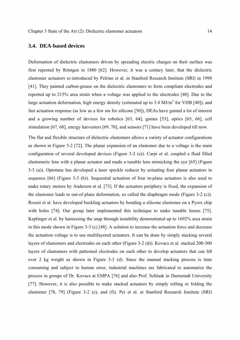
3.4. DEA-based devices
Deformation of dielectric elastomers driven by spreading electric charges on their surface was
first reported by Röntgen in 1880 [62]. However, it was a century later, that the dielectric
elastomer actuators re-introduced by Pelrine et al. in Stanford Research Institute (SRI) in 1998
[41]. They painted carbon-grease on the dielectric elastomers to form compliant electrodes and
reported up to 215% area strain when a voltage was applied to the electrodes [40]. Due to the
large actuation deformation, high energy density (estimated up to 3.4 MJ/m3 for VHB [40]), and
fast actuation response (as low as a few ms for silicone [50]), DEAs have gained a lot of interest
and a growing number of devices for robotics [63, 64], games [53], optics [65, 66], cell
stimulation [67, 68], energy harvesters [69, 70], and sensors [71] have been developed till now.
The flat and flexible structure of dielectric elastomers allows a variety of actuator configurations
as shown in Figure 3-2 [72]. The planar expansion of an elastomer due to a voltage is the main
configuration of several developed devices (Figure 3-2 (a)). Carpi et al. coupled a fluid filled
elastomeric lens with a planar actuator and made a tunable lens mimicking the eye [65] (Figure
3-3 (a)). Optotune has developed a laser speckle reducer by actuating four planar actuators in
sequence [66] (Figure 3-3 (b)). Sequential actuation of four in-plane actuators is also used to
make rotary motors by Anderson et al. [73]. If the actuators periphery is fixed, the expansion of
the elastomer leads to out-of plane deformation, so called the diaphragm mode (Figure 3-2 (c)).
Rosset et al. have developed buckling actuators by bonding a silicone elastomer on a Pyrex chip
with holes [74]. Our group later implemented this technique to make tunable lenses [75].
Keplinger et al. by harnessing the snap through instability demonstrated up to 1692% area strain
in this mode shown in Figure 3-3 (c) [48]. A solution to increase the actuation force and decrease
the actuation voltage is to use multilayered actuators. It can be done by simply stacking several
layers of elastomers and electrodes on each other (Figure 3-2 (d)). Kovacs et al. stacked 200-300
layers of elastomers with patterned electrodes on each other to develop actuators that can lift
over 2 kg weight as shown in Figure 3-3 (d). Since the manual stacking process is time
consuming and subject to human error, industrial machines are fabricated to automatize the
process in groups of Dr. Kovacs at EMPA [76] and also Prof. Schlaak in Darmstadt University
[77]. However, it is also possible to make stacked actuators by simply rolling or folding the
elastomer [78, 79] (Figure 3-2 (e), and (f)). Pei et al. at Stanford Research Institute (SRI)

15 3.4. DEA-based devices
patterned the electrode before rolling the elastomer and developed a multi-degree of freedom
actuator that can bend in two different directions (Figure 3-2 (g)). They later made a walking
robot using six of these bending actuators (Figure 3-3 (f)) [80].
Figure 3-2- Basic configurations for dielectric elastomer actuators [72]
The extender DEAs can be coupled to a shaft to deliver force (Figure 3-2 (i)). In the framed
mode, the output shaft is attached between two extender actuators and moves in both directions.
This device is first developed at SRI (Figure 3-3 (g)) and is now used by Artificial Muscle INC
to provide haptic feedback for games on iPhone or iPad by simply shaking the device at certain
frequencies [53]. The DEAs can also be coupled to different rigid mechanisms, which has been
demonstrated by Plante et al. to develop bistable mechanisms for robotics [64] (Figure 3-3 (h)).

Chapter 3 State of the Art (2): Dielectric elastomer actuators 16
Figure 3-3- Selection of developed DEA based actuators at different configurations. (a) Tunable Lens in the planar mode [65]. (b) Laser speckle reducer by optotune [66]. (c) Diaphragm mode actuator with up to 1692% area strain [48]. (d) Multilayered stack actuator [81]. (e) Folded multilayer actuator [79]. (f) Parallel plate robot with six bending two degree of freedom rolled actuators [80]. (g) Framed actuator used by AMI company to add haptic feedback to phone based games [53]. (h) Framed Bowtie actuator [64].
The DEA devices range from mm scale (Braille displays [82], tactile displays [83]) to cm scale
(compact motors [73], peristaltic pumps [84]) to meter scale (energy harvesting from ocean
waves [85] and airships [63]), as demonstrated in Figure 3-4 . However, miniaturization of
dielectric elastomer actuators is challenging due to lack of reliable and reproducible methods to
pattern µm-scale compliant electrodes. In the next section, I will discuss the available techniques
to pattern µm-mm scale compliant electrodes for dielectric elastomer actuators and briefly
review the miniaturized devices developed up to now.
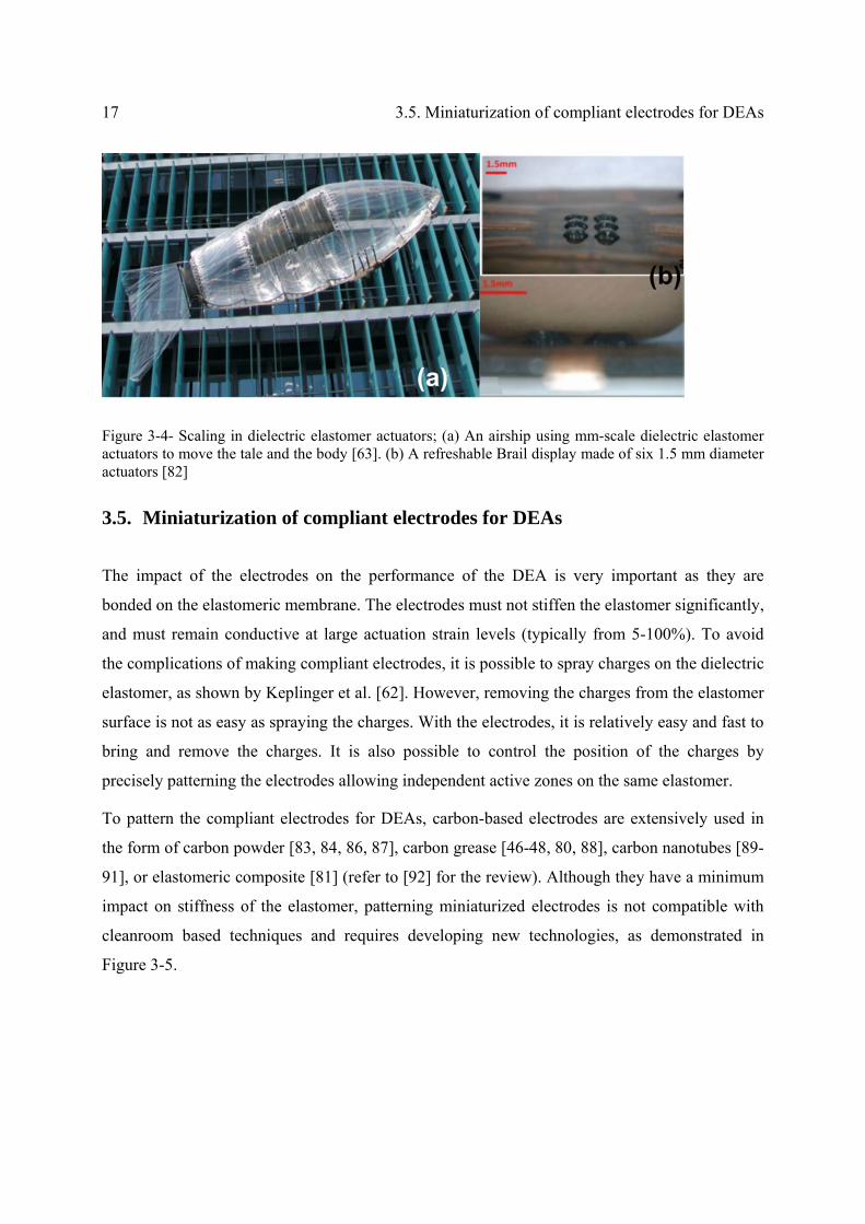
17 3.5. Miniaturization of compliant electrodes for DEAs
Figure 3-4- Scaling in dielectric elastomer actuators; (a) An airship using mm-scale dielectric elastomer actuators to move the tale and the body [63]. (b) A refreshable Brail display made of six 1.5 mm diameter actuators [82]
3.5. Miniaturization of compliant electrodes for DEAs
The impact of the electrodes on the performance of the DEA is very important as they are
bonded on the elastomeric membrane. The electrodes must not stiffen the elastomer significantly,
and must remain conductive at large actuation strain levels (typically from 5-100%). To avoid
the complications of making compliant electrodes, it is possible to spray charges on the dielectric
elastomer, as shown by Keplinger et al. [62]. However, removing the charges from the elastomer
surface is not as easy as spraying the charges. With the electrodes, it is relatively easy and fast to
bring and remove the charges. It is also possible to control the position of the charges by
precisely patterning the electrodes allowing independent active zones on the same elastomer.
To pattern the compliant electrodes for DEAs, carbon-based electrodes are extensively used in
the form of carbon powder [83, 84, 86, 87], carbon grease [46-48, 80, 88], carbon nanotubes [89-
91], or elastomeric composite [81] (refer to [92] for the review). Although they have a minimum
impact on stiffness of the elastomer, patterning miniaturized electrodes is not compatible with
cleanroom based techniques and requires developing new technologies, as demonstrated in
Figure 3-5.

Chapter 3 State of the Art (2): Dielectric elastomer actuators 18
Figure 3-5- Different techniques to pattern carbon electrodes. (a) Using a shadow mask to selectively protect part of the elastomeric membrane. The carbon-based electrode material can then be dispensed (for example by spraying) on the surface. The shadow mask is subsequently removed to expose the patterned electrode. (b) Using a patterned elastomeric stamp to pick-up the electrode material and apply it on the elastomeric membrane. (c) Using standard printing techniques, such as drop-on-demand inkjet printing [92].
Aschwanden et al. have pattern 100 µm wide electrodes by stamping carbon powder on an
acrylic based membrane (VHB 9460) to make tunable gratings, as shown in Figure 3-6 [87].
Since VHB is sticky, the particles remain on the surface. But using the carbon powders on
silicone elastomers is problematic as the loose particles tend to detach from the membrane and
lose the conductivity leading to short life time. The group of Prof. Schlaak have sprayed the
carbon powder over a shadow mask to pattern mm size electrodes and cover it with another
silicone membrane layer to avoid detaching the electrodes from the membrane [93]. With this
technology they have developed a tactile display with mm sized electrodes [83]. It is also
possible to disperse the carbon powder in an elastomeric matrix and then pattern it on the surface
and let it cure. It enhances the adhesion of the carbon particles to the surface. I have patterned as
small as 150 µm wide elastomeric carbon-based ink on a silicone elastomer using a
commercially available pad-printer, which will be discussed in section 4.8 [94, 95].
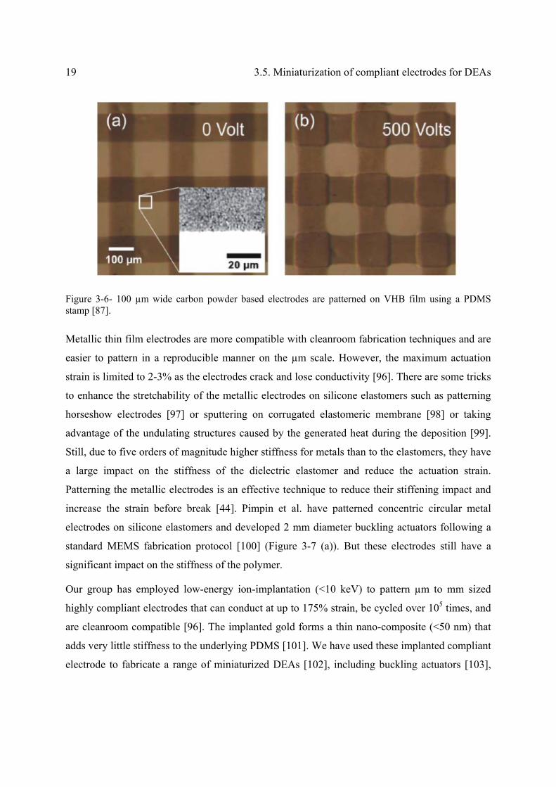
19 3.5. Miniaturization of compliant electrodes for DEAs
Figure 3-6- 100 µm wide carbon powder based electrodes are patterned on VHB film using a PDMS stamp [87].
Metallic thin film electrodes are more compatible with cleanroom fabrication techniques and are
easier to pattern in a reproducible manner on the µm scale. However, the maximum actuation
strain is limited to 2-3% as the electrodes crack and lose conductivity [96]. There are some tricks
to enhance the stretchability of the metallic electrodes on silicone elastomers such as patterning
horseshow electrodes [97] or sputtering on corrugated elastomeric membrane [98] or taking
advantage of the undulating structures caused by the generated heat during the deposition [99].
Still, due to five orders of magnitude higher stiffness for metals than to the elastomers, they have
a large impact on the stiffness of the dielectric elastomer and reduce the actuation strain.
Patterning the metallic electrodes is an effective technique to reduce their stiffening impact and
increase the strain before break [44]. Pimpin et al. have patterned concentric circular metal
electrodes on silicone elastomers and developed 2 mm diameter buckling actuators following a
standard MEMS fabrication protocol [100] (Figure 3-7 (a)). But these electrodes still have a
significant impact on the stiffness of the polymer.
Our group has employed low-energy ion-implantation (<10 keV) to pattern µm to mm sized
highly compliant electrodes that can conduct at up to 175% strain, be cycled over 105 times, and
are cleanroom compatible [96]. The implanted gold forms a thin nano-composite (<50 nm) that
adds very little stiffness to the underlying PDMS [101]. We have used these implanted compliant
electrode to fabricate a range of miniaturized DEAs [102], including buckling actuators [103],

Chapter 3 State of the Art (2): Dielectric elastomer actuators 20
tunable lenses [104] or tunable acoustic filters [105]. In Chapter 5, I will discuss how to further
miniaturize the ion-implanted electrodes. By ion-implantation I have patterned 100 µm wide
electrodes that are conductive till 118% area strain that the actuator fails due to electrical
breakdown, (results are shown in section 7.4) [106].
Figure 3-7- Patterned 170 nm Cr/Au/Cr electrodes evaporated on a 30-40 μm thick DowCorning Sylgard 186 membrane on a buckling actuator [100].
3.6. Conclusion
In this chapter, dielectric elastomer actuators and their actuation principle was introduced. The
field is rapidly growing and there has been an extensive effort on the configurations, materials,
and compliant electrodes of DEAs. The basic configuration and the major developed devices
were briefly reviewed. The impact of the polymers and compliant electrodes on the actuators’
performance were discussed and the efforts on developing an optimized polymer for DEAs have
been mentioned. In the next chapter, employing nonlinear theoretical formulations, the
electromechanical behavior of DEAs at large deformation is analyzed. A deeper insight in the
right choice of the polymers is provided by the theoretical calculations.

Chapter 4 Theoretical analysis of dielectric
elastomer actuators with experimental validations
4.1. Summary
The electromechanical behavior of dielectric elastomer actuators is theoretically analyzed. The
nonlinear stress-strain correlation (so called hyperelastic material properties) of dielectric
elastomers are derived from the experimental pull-test and used to solve the nonlinear governing
equations of DEAs at different prestretch modes. It is explained that the existing theoretical
guidelines in the literature based on the traditionally used VHB films cannot be directly
implemented for silicone elastomers. By comparing the electromechanical performance of two
different silicone elastomers at different prestretch modes, instructions to choose the right
polymer and prestretch ratio to achieve large actuation is presented. The theoretical calculations
are verified by experimental data and it is demonstrated that miniaturization allows higher
actuation strain by hindering the loss of tension. Up to 85% linear actuation strain is generated
with a 300 µm x 300 µm dielectric elastomer actuator.
The essence of this chapter is accepted for publication in the Journal of Applied Physics Letter
2013 (DOI: 10.1063/1.4793420). The theoretical formulations are also published in Proceeding
of SPIE 2013 San Diego.

Chapter 4 Theoretical analysis of DEAs 22
4.2. Introduction
Giant voltage-triggered deformations up to 360% linear strain with clamped elastomer [46],
488% area strain with membrane under dead loads [47] and 1692% area strain on membranes
mounted on an air chamber [48] have been reported using polyacrylate VHB films from 3M. As
mentioned in section 3.3 to achieve reproducible and fast actuation, and to prevent creep
phenomenon, one must switch from VHB to materials with negligible viscoelastic behavior such
as some classes of polydimethylsiloxanes (PDMS) or polyurethanes. However, the existing
theoretical guidelines for large actuation deformation of DEAs developed based on VHB films
cannot be directly implemented to castable elastomers [60, 107]. Unlike VHB which is available
as films with predefined thicknesses, PDMS or polyurethane are available as viscous liquids that
can be polymerized after casting to form membranes of any desired thickness. This decouples the
thickness of the elastomer from the prestretch ratio allowing to select them independently. For
most practical materials, the thickness of the elastomer after prestretch is limited by design
considerations and to avoid membrane rupture. I will show that when the thickness reduction is
excluded from the prestretch, the actuation voltage increases due to stiffening of the elastomer at
high prestretch ratios. By theoretical analysis, I introduce the optimum prestretch ratio sufficient
to suppress the pull-in instability allowing large deformation with the lowest actuation voltage.
Compared to biaxial prestretch, uniaxial prestretch leads to a higher voltage-induced strain in the
transverse direction. However, the elastomer is more prone to lose tension in the direction with
small prestretch ratio and fail by forming wrinkles. I experimentally demonstrate that
miniaturization hinders the loss of tension and report up to 85 % linear voltage-triggered strain
with 300 µm x 300 µm actuators on PDMS-based elastomers.
4.3. Theoretical formulations
For the theoretical analysis, an elastomeric membrane is considered with initial dimensions of
L1, L2, and t0, which is then prestretched by ratios of λp1 and λp2 in directions 1 and 2,
respectively, to achieve the desired thickness ti for the device (Figure 4-1). To keep the prestretch
in the elastomer, it is normally fixed on a frame, which can be simulated by applying constant
forces of P1 and P2, as shown in Figure 4-1 (b). The value of the forces corresponds to the

23 4.3. Theoretical formulations
prestretch ratios and the strain energy of the elastomer. Then, the compliant electrodes assumed
to cause no stiffening for this analysis, are patterned over the whole surface and a voltage is
applied to the electrodes reducing the elastomer’s thickness due to the Maxwell stress, which
results in planar expansion. Since the material is incompressible, λ1λ2λ3=1, where, λi is the
stretch ratio in direction i.
Figure 4-1- Schematic of a dielectric elastomer actuator; a) A membrane is of initial dimensions of L1, L2 and t0. b) The membrane is prestretched by ratios of λp1 and λp2 in directions 1 and 2, respectively and is subjected to constant forces corresponding to the prestretch ratios. c) Compliant electrodes are patterned and a voltage is applied to the electrodes leading to planar expansion and thickness reduction.
The electrostatic pressure on the elastomer because of the applied voltage is equal to
2f
2
t
VP (5)
where, V is the applied voltage, tf is the final thickness, and ε is the permittivity of the elastomer.
4.3.1. Small actuation strain
For small strain levels (less than 10%) a linear correlation exists between stress and strain and
the elastomers follow Hooke’s law. In this case, the strain in the material is linearly dependent to
the principle stresses
33
22
11
33
22
11
1
1
1
Y
1
(6)
where, ε11, ε22, and ε33 are the strains in directions 1, 2, and 3, respectively. σ11, σ 22, and σ 33 are
the principal stresses in directions 1, 2, and 3, respectively. Y is the young’s modulus of the
elastomer calculated from the slope of the stress-strain curve at low strain levels, and υ is the
Poisson ratio, which is equal to 0.5 for incompressible elastomers at small deformations.

Chapter 4 Theoretical analysis of DEAs 24
For non-prestretched elastomer, the stress in the thickness is equal to the Maxwell stress due to
the voltage and the in-plane stresses are equal to zero.
σ11= σ 22=0, and σ 33= 2f
2
t
V (7)
The actuation strains are then calculated from Equation (6)
20
233
2
2f
2
33t)1(
V
YtY
V
233
2211
(8)
However, for large deformations or for prestretched elastomers Hooke’s law is not valid and the
stress-strain relationship is highly nonlinear. The dielectric elastomer can be correctly modeled
with the hyperelastic material models.
4.3.2. Material modeling
I have characterized the stress-strain curve of each elastomer by uniaxial test using a pull-test
instrument (Instron® 3343, Noorwood, USA). A 100-150 µm thick elastomeric membrane is
prepared and cut to narrow strips with a laser cutter to avoid introducing defects. The length to
width ratio of the strips is chosen higher than 7, which is essential to simulate a uniaxial test. If
the width of the specimen is larger than the length, the experiment approaches to pure shear test
for rubbers [108]. The specimen is put between the grippers straightly to distribute the tension
uniformly over the cross-section. The grips are moving apart from each other at the rate of 25-50
mm/min and the force is recorded by a load cell at one of the grippers. Knowing the initial
dimensions of the specimen and the measured force-displacement data, the true stress in the
elastomer is calculated versus the strain. Figure 4-2, shows the stress-strain relationship of a 120
µm thick Sylgard 186 membrane, which broke at the strain of 317%.

25 4.3. Theoretical formulations
Figure 4-2- True stress respect to strain of Sylgard 186 membrane in a uniaxial test using a Pull-test instrument.
The non-linear behavior of elastomers is described with hyperelastic models. The stress-strain
relationship of hyperelastic materials is defined by nonlinear strain energy functions. Different
hyperelastic material models have been developed, such as Neo-Hookean, Ogden [109], Yeoh
[110], Arruda-Boyce [111], and Gent [112]. Elastomers have a maximum elongation at break
limited by their polymeric chain length. Gent model is a simple approximation of the Arruda-
Boyce model that can well simulate the strain stiffening of the elastomers as it has a vertical
asymptote at the maximum elongation. In the theoretical calculations, in this thesis, I have used
the Gent model, which could best fit with the experimental data. In the Gent model, the strain
energy function is defined as [112]
)J
31(ln
2
J),,(W
m
23
22
21m
321
(9)
where, W (λ1, λ2, λ3) is the strain energy function, and λ1, λ2, λ3 are the ratio of final length over
the initial length also called stretch ratios along directions of 1, 2, and 3 (see Figure 4-1). µ is the
shear modulus and Jm is the other material constant related to the maximum stretch. When
λ12+λ2
2+λ32-3 approaches to Jm, the Gent model stiffens sharply. To determine the material
properties for each elastomer, µ and Jm, the stress in the material by the uniaxial stretch is

Chapter 4 Theoretical analysis of DEAs 26
calculated using the defined energy function and fitted to the experimental stress-strain curves.
For the hyperelastic materials, the Cauchy stresses are defined by the following equations [109]
p),,(W
1
321111
(10)
p),,(W
2
321222
(11)
p),,(W
3
321333
(12)
where, p is the hydrostatic pressure, which is a constant depending on the boundary conditions.
In the case of uniaxial stretch
03322 (13)
Resulting in
32 (14)
The elastomers are considered incompressible,
1321 (15)
therefore,
1
321
(16)
The Cauchy stresses are calculated by combining equations (9)-(12) as follow
p3)(J
J2
32
22
1m
m2
111
(17)
0p)3)(J(
J2
32
22
1m1
m3322
(18)
The constant p is calculated from equation (18) and substituted in equation (17) to calculate the
true stress in the elastomer in direction 1 as a function of the stretch ratio
27 4.3. Theoretical formulations
)3)(J
J)(
1(
23
22
21m
m
1
2111
(19)
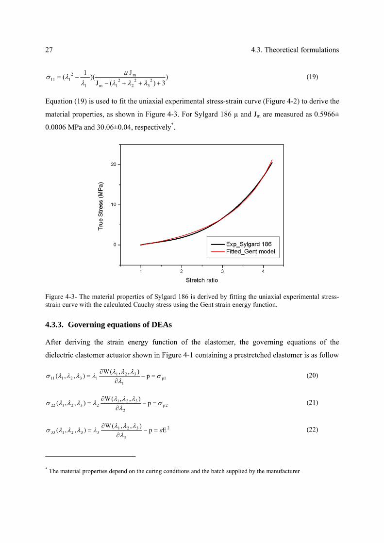
Equation (19) is used to fit the uniaxial experimental stress-strain curve (Figure 4-2) to derive the
material properties, as shown in Figure 4-3. For Sylgard 186 µ and Jm are measured as 0.5966±
0.0006 MPa and 30.06±0.04, respectively*.
Figure 4-3- The material properties of Sylgard 186 is derived by fitting the uniaxial experimental stress-strain curve with the calculated Cauchy stress using the Gent strain energy function.
4.3.3. Governing equations of DEAs
After deriving the strain energy function of the elastomer, the governing equations of the
dielectric elastomer actuator shown in Figure 4-1 containing a prestretched elastomer is as follow
1p1
321132111 p
),,(W),,(
(20)
2p2
321232122 p
),,(W),,(
(21)
2
3
321332133 Ep
),,(W),,(
(22)
* The material properties depend on the curing conditions and the batch supplied by the manufacturer
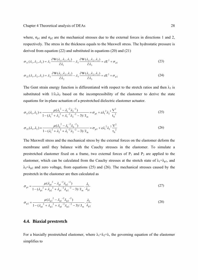
Chapter 4 Theoretical analysis of DEAs 28
where, σp1 and σp2 are the mechanical stresses due to the external forces in directions 1 and 2,
respectively. The stress in the thickness equals to the Maxwell stress. The hydrostatic pressure is
derived from equation (22) and substituted in equations (20) and (21)
1p2
3
3213
1
321132111 E
),,(W),,(W),,(
(23)
2p2
3
3213
2
321232122 E
),,(W),,(W),,(
(24)
The Gent strain energy function is differentiated with respect to the stretch ratios and then λ3 is
substituted with 1/λ1λ2 based on the incompressibility of the elastomer to derive the state
equations for in-plane actuation of a prestretched dielectric elastomer actuator.
20
22
22
11pm
22
21
22
21
22
21
21
2111t
V
J/)3(1
)(),(
(25)
20
22
22
12pm
22
21
22
21
22
21
22
2122t
V
J/)3(1
)(),(
(26)
The Maxwell stress and the mechanical stress by the external forces on the elastomer deform the
membrane until they balance with the Cauchy stresses in the elastomer. To simulate a
prestretched elastomer fixed on a frame, two external forces of P1 and P2 are applied to the
elastomer, which can be calculated from the Cauchy stresses at the stretch state of λ1=λp1, and
λ2=λp2 and zero voltage, from equations (25) and (26). The mechanical stresses caused by the
prestretch in the elastomer are then calculated as
1p
1
m2
2p2
1p2
2p2
1p
22p
21p
21p
1p .J/)3(1
)(
(27)
2p
2
m2
2p2
1p2
2p2
1p
22p
21p
22p
2p .J/)3(1
)(
(28)
4.4. Biaxial prestretch
For a biaxially prestretched elastomer, where λ1=λ2=λ, the governing equation of the elastomer
simplifies to

29 4.4. Biaxial prestretch
pmJ
tV
/)32(1
)(42
42
2
0 (29)
pm4
p2
p
4p
2p
p .J/)32(1
)(
(30)
The electromechanical behavior of a 50 µm thick Sylgard 186 membrane biaxially prestretched
at different ratios and exposed to a high voltage is calculated using equations (29) and (30) and is
plotted in Figure 4-4. The stretch ratio in the x axis is referenced to the non-stretched state, and
to calculate the actuation stretch, the stretch ratio should be divided to the prestretch ratio.
Figure 4-4- Calculated electromechanical behavior of a 50 µm thick elastomer before prestretch (Sylgard 186) at different biaxial prestretch ratios. The pull-in instability is suppressed by prestretching and the actuation voltage is reduced due to thickness reduction because of prestretching. The x-axis is the stretch ratio of the elastomer referenced to the non-stretched state. To calculate the actuation stretch the stretch ratio should be divided to the prestretch ratio.
For a non-prestretched elastomer (λp=1), the actuation stretch increases with the applied voltage
up to λ=1.26 and by further increasing the voltage, it snaps to λ=3.8, where the device fails by
the electric breakdown. This mode of instability is called pull-in instability. Biaxially
prestretching the elastomer suppresses the pull-in instability. The required applied voltage to
actuate the device is also decreased when the elastomer with a fixed initial thickness is
prestretched, as shown in Figure 4-4. This is mainly due to the thickness reduction by

Chapter 4 Theoretical analysis of DEAs 30
prestretching and is mostly the case for VHB films which are available as films with fixed
thicknesses. This type of electromechanical response has been reported in several articles based
on theoretical or experimental results, in which VHB films were used in making the DEAs [46,
60, 107, 113-115]. However, silicones or polyurethanes are initially available as viscous liquids
and can be polymerized after casting to form membranes of any desired thickness. This
decouples the thickness of the elastomer from the prestretch ratio allowing to select them
independently. For most practical materials, the thickness of the elastomer after prestretch is
limited. When a constant thickness after prestretching (30 µm) is considered for the actuator,
increasing the biaxial prestretch ratio leads to higher actuation voltage, as shown in Figure 4-5.
Biaxial prestretch of 1.5 is sufficient to suppress the pull-in instability and further prestretching
deteriorates the actuator’s performance by stiffening it and increasing the required actuation
voltage for a given displacement.
Figure 4-5- Electromechanical behavior of a Sylgard 186 elastomer exposed to high voltage at different prestretch ratios. Thickness of the actuator after biaxial prestretching is fixed to 30 µm. A prestretch ratio of 1.5 is sufficient to suppress the pull-in instability and a higher prestretch ratio is not desirable as it stiffens the elastomer and deteriorates the performance of the actuator.
To easily compare the expansion of the elastomer due to the applied voltage, the stretch is
divided to the initial prestretch to calculate the actuation stretch (the visible stretch ratio due to
actuation), which is plotted in Figure 4-6. It can be seen that a slight prestretch of about 20%
pushes back the pull-in instability to 40% strain without stiffening or increasing the applied

31 4.4. Biaxial prestretch
voltage. However, to completely suppress the pull-in instability, initial prestretch of 1.5 is
required. There is no reason to prestretch the elastomer more, as it will stiffen the elastomer and
increase the actuation voltage.
Figure 4-6- Electromechanical behavior of a Sylgard 186 elastomer exposed to high voltage at different prestretch ratios. Slight biaxial prestretch of 20% pushes back the pull-in instability to 40% actuation strain without stiffening the elastomer and increasing the actuation voltage.
The calculated prestretch ratios to optimize the device performance are dependent on the
mechanical properties of the elastomer and should be recomputed for another elastomer type. I
have measured the stress-strain curve of another silicone elastomer, CF 18-2186 (Nusil, silicone
technology, USA) using the uniaxial pull-test. By fitting a line to the stress-strain curve for lower
than 15% strain, the Young’s modulus of this elastomer is derived and compared with the
Young’s modulus of Sylgard 186 obtained with the same technique. The Young’s modulus of CF
18 is 3.5 times lower than Sylgard 186 and has an elongation rate of 6.5, and therefore, it seems
that it is a good candidate for dielectric elastomer actuations. By fitting the calculated true stress
to the measured stress strain curve, the Gent material properties are derived as µ=0.23 MPa, and
Jm=95.0. The voltage-induced stretch of this elastomer exposed to a high voltage when biaxially
prestretched at different stretch ratios (the thickness after prestretch is 30 µm) is plotted in Figure
4-7 (a). It is observed that biaxial prestretch ratio of about 2.5 is required to suppress the pull-in
instability completely, while it is only 1.5 for Sylgard 186. Figure 4-7 (b) magnifies the same

Chapter 4 Theoretical analysis of DEAs 32
graphs at lower stretch ratios to investigate when the pull-in occurs. For zero prestretch ratio the
pull in instability occurs at stretch ratio of 1.26 and 2137 V. For all non-prestretched elastomers,
the pull-in instability occurs at the same actuation stretch but at lower voltages for softer
elastomers. When the elastomer is 1.5 times biaxially prestretched, the pull-in instability is
pushed back to actuation stretch of 1.44 at 2529 V. To completely suppress the pull-in instability,
biaxial prestretch ratio of 2.5 is required, which also highly stiffens the elastomer and increases
the actuation voltage, consequently resulting in failure at smaller actuation strain due to the
electric breakdown. The orange line in Figure 4-7 (b) represents when the electric field in the
elastomer reaches the breakdown electric field assumed to be 250 V/µm. It should be mentioned
that the breakdown strength of the PDMS elastomers increases by the prestretch ratio and is
much lower for a non-prestretched membrane.
Figure 4-7- (a) Electromechanical behavior of a Nusil CF-18 elastomeric membrane exposed to high voltage at different biaxial prestretch ratios. (b) Magnified version of (a) at smaller actuation stretch showing that the pull-in instability is pushed back to 1.44 by a prestretch ratio of 1.5. Further prestretch although suppresses the pull-in instability but is not helpful as it stiffenes the elastomer leading to failure by electric breakdown at lower actuation stretch. The orange line represents when the the electric field in the elastomer approaches 250 V/µm and the cross marks show when the pull-in instability occurs.
4.5. Uniaxial prestretch
Uniaxial prestretching offers larger actuation strain for DEAs in the case of fixed thickness after
prestretch. The elastomer stiffens in the prestretched direction leading to higher actuation strain
in the transverse direction. The pull-in instability is also suppressed but at higher prestretch ratios
compared to the biaxial prestretch. The electromechanical behavior of the dielectric elastomer is
derived by solving the equations (25) and (26). First two equations are subtracted from each

33 4.5. Uniaxial prestretch
other and numerically solved to obtain λ2 with respect to a defined λ1 and then the voltage is
calculated for each λ1 and λ2. The minimum uniaxial prestretch ratio to achieve monotonic
voltage-strain curve is 2.75 for Sylgard 186, as shown in Figure 4-8. The actuation stretch along
and perpendicular to the prestretch direction respect to the applied voltage are plotted in Figure
4-8 (a) and (b), respectively. By increasing the prestretch ratio, the voltage-triggered stretch
reduces along the prestretch direction and increases in the transverse direction. In contrast with
the biaxial prestretch, the actuation voltage is not increased with the prestretch ratio and
therefore, much higher strain can be achieved in the transverse direction before electrical
breakdown of the elastomer. It should be noted that uniaxial prestretching leads to anisotropic
strain profile approaching to uniaxial at high prestretch ratios.
Figure 4-8- Electromechanical behavior of uniaxially prestretched Sylgard 186 membranes exposed to high voltage at different prestretch ratios. (a) Along the prestretched direction. (b) Perpendicular to the prestretched direction. Higher voltage-triggered stretch can be achieved in the transverse direction without increasing the actuation voltage. In the theoretical calculations, the thickness of elastomer is fixed to 30 μm after prestretch.
Performing the same calculations for a Nusil CF-18 elastomeric membrane indicates a minimum
prestretch ratio of 5 to suppress the pull-in instability in the prestretched direction (λ1), as shown
in Figure 4-9 (a). If the membrane can successfully be prestretched and fixed on a frame, large
actuation strain can be achieved in the transverse direction (λ2) (Figure 4-9 (b)). However, at
high prestretch ratios, the membrane becomes very susceptible to rupture. I have not been able to
make stable actuators with prestretch ratios of higher than 3.5 with this elastomer. In conclusion,
although this polymer is softer than Sylgard 186 and needs less actuation voltage, it is not
possible to practically achieve large actuation strain in the uniaxial prestretch mode. That’s why;
I have chosen Sylgard 186 in the fabrication of the dielectric elastomer actuators.

Chapter 4 Theoretical analysis of DEAs 34
By comparing the electromechanical performance of two silicone type dielectric elastomer
actuator, it has been shown that the softest elastomer is not necessarily the best choice for
dielectric elastomer actuators. Looking back to section 3.3, where I reviewed the efforts on
designing the optimized polymer for DEAs, I would like to point out that for large deformation
(>20%) actuators, the hyperelastic properties should be optimized not only the Young’s modulus.
Figure 4-9- Electromechanical behavior of uniaxially prestretched Nusil Cf-18 membranes exposed to high voltage at different prestretch ratios. (a) Along the prestretched direction. (b) Perpendicular to the prestretched direction. Minimum prestretch ratio of 5 is required to suppress the pull-in instability in the λ2 direction. The thickness of elastomer is fixed to 30 μm after prestretch.
4.6. Optimum prestretch conditions
As shown in the previous section, prestretching the elastomer is a key factor for enhancing the
electromechanical response of dielectric elastomer actuators as it suppresses the pull-in
instability and allows higher actuation strain. However, there is an optimum prestretch ratio
sufficient to suppress the pull-in instability for each type of elastomer and prestretch mode.
Higher prestretch ratios will unnecessarily stiffen the elastomer and increase the actuation
voltage. The voltage-induced stretch (λ2/λP2) of Sylgard 186 elastomer at the optimum ratios
(where the pull-in instability is suppressed) under different prestretch modes (biaxial, pure shear,
uniaxial) is plotted in Figure 4-10. Above the optimum ratios, there is no instability and the
Hessian of the free energy function is definite positive, as first introduced by Zhao et al. [116].
For Sylgard 186, that has elongation at break of 4, a biaxial prestretch of 1.5 is enough to achieve
monotonic voltage-strain curve. Higher prestretch ratios are required for pure shear (λp2=1) and
uniaxial prestretch modes. The maximum response is then limited by breakdown voltage of the
elastomer. The uniaxial prestretch mode allows the highest actuation stretch (2.38) in the
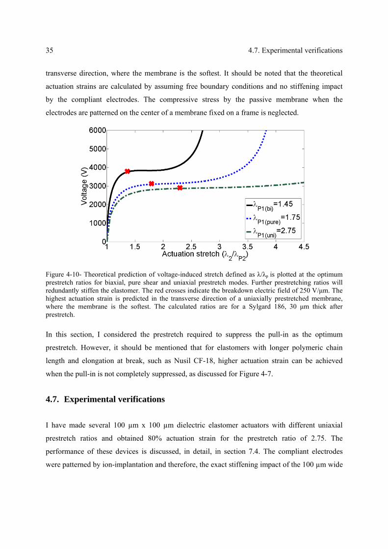
35 4.7. Experimental verifications
transverse direction, where the membrane is the softest. It should be noted that the theoretical
actuation strains are calculated by assuming free boundary conditions and no stiffening impact
by the compliant electrodes. The compressive stress by the passive membrane when the
electrodes are patterned on the center of a membrane fixed on a frame is neglected.
Figure 4-10- Theoretical prediction of voltage-induced stretch defined as λ/λp is plotted at the optimum prestretch ratios for biaxial, pure shear and uniaxial prestretch modes. Further prestretching ratios will redundantly stiffen the elastomer. The red crosses indicate the breakdown electric field of 250 V/μm. The highest actuation strain is predicted in the transverse direction of a uniaxially prestretched membrane, where the membrane is the softest. The calculated ratios are for a Sylgard 186, 30 μm thick after prestretch.
In this section, I considered the prestretch required to suppress the pull-in as the optimum
prestretch. However, it should be mentioned that for elastomers with longer polymeric chain
length and elongation at break, such as Nusil CF-18, higher actuation strain can be achieved
when the pull-in is not completely suppressed, as discussed for Figure 4-7.
4.7. Experimental verifications
I have made several 100 µm x 100 µm dielectric elastomer actuators with different uniaxial
prestretch ratios and obtained 80% actuation strain for the prestretch ratio of 2.75. The
performance of these devices is discussed, in detail, in section 7.4. The compliant electrodes
were patterned by ion-implantation and therefore, the exact stiffening impact of the 100 µm wide

Chapter 4 Theoretical analysis of DEAs 36
electrodes on the dielectric elastomer is not known to compare with the theoretical calculations
(refer to the next chapter for more detail on the stiffening impact of the ion-implanted
electrodes).
To verify the theoretical predictions, I have fabricated and tested different actuators with carbon
based electrodes at multiple prestretch modes. A thin layer of carbon elastomeric matrix (~2 µm)
is patterned using a commercially available Pad printer [94]. Since the stiffness of the elastomer
used to make the carbon based ink is 6 times lower than the main dielectric elastomer and the
electrodes are very thin, the stiffening impact of the electrodes are neglected. Therefore, the
presented theoretical calculations can be compared with the experimental measurements.
Silicone membranes (Sylgard 186) with various thicknesses are casted using an applicator and
prestretched with different prestretch ratios to achieve 30 µm thick elastomer and then fixed on a
frame [106]. Carbon powder is dispersed in an elastomeric matrix and stamped at the center of
the frame to pattern thin compliant electrodes [92] on both sides of the membrane, as shown in
Figure 4-11.
Figure 4-11- Fabricated 1.5 mm diameter DEA with carbon based compliant electrodes
Then, the in-plane voltage-induced stretches of the actuators are recorded and compared with the
theoretical calculations depicted in Figure 4-12. I have observed that the electric field strength of
the elastomer is enhanced from 100 V/µm for non-prestretched films [68, 74, 106] to 250 V/µm
by 1.75 biaxial prestretch.

37 4.7. Experimental verifications
Figure 4-12- Voltage-induced of dielectric elastomer actuators made with two different prestretch conditions . The x and o data points are the measured linear stretch expansion on 1.5 mm diameter and 300 x 300 µm2 actuators, respectively. The actuator under biaxial prestretch is failed at 1.32 stretch (32% strain) due to electric breakdown at 250 V/µm. The actuators with anisotropic prestretch mode failed due to the loss of tension at 20% and 85% strain for 1.5 mm diamter and 300x300 µm2 actuators, respectively.
Since a thin membrane cannot sustain compressive strain, the actuators are prone to lose tension
in the direction with a small prestretch ratio in the anisotropic prestretch mode. As the actuated
area expands due to the voltage, it experiences compressive stress from the passive area till the
tensile stress on the actuator becomes zero and the membrane buckles out of plane in the form of
wrinkles [117], as shown in Figure 4-13. The actuator is 1.5 mm diameter patterned on a 20 mm
diameter membrane fixed on a frame. The prestretch ratios are 2.75 and 0.9 in the y and x
directions, respectively. The loss of tension occurs at 20% strain (1.2 actuation stretch) and
prohibits higher actuation stretch predicted by the theoretical analysis, in which the
electromechanical equations were solved under free boundary conditions.

Chapter 4 Theoretical analysis of DEAs 38
Figure 4-13- 1.5 mm diameter DEA is made on a membrane with prestretch ratios of λpx=0.9, λpy=2.6 and fixed on a 20 mm frame. The actuator experiences loss of tension at 23% linear strain and wrinkles appear on the membrane.
4.8. Miniaturization of the actuators
Miniaturization of the actuators fixed on the same frame effectively holds back the loss of
tension allowing higher actuation strain. I fabricated 300 µm x 300 µm actuators on a 30 µm
thick elastomer with prestretching ratios of λpy=2.8 and λpx=0.9, which is fixed on a 40 mm
diameter frame. The actuation strain enhanced by 4 times compared to the 1.5 mm diameter
actuator and 85% linear strain (1.85 stretch) achieved till the wrinkles appeared, as shown in
Figure 4-14. In a simplified model, when the linear stretches are matched between the passive
and active regions at the equilibrium, we have
)1(L
L1 act1
pas1
act1pas1 (31)
where, L1act and L1pas are the initial lengths, and λ1act and λ1pas are the linear stretch ratios of the
active and passive regions in direction 1. Decreasing the size of the active to passive area reduces
the stretch ratio and the consequent Cauchy stress in the passive region. Therefore, the effect of
the passive region on the actuator diminishes by scaling down the actuator, holding back the loss
of tension. The same effect can be achieved by enlarging the passive area. To precisely analyze
effect of the passive region, its inhomogeneous stress field should be analyzed considering a

39 4.9. Conclusion
continuous deformation between the passive and active region as demonstrated by Koh et al. [60]
and Plante et al. [114].
Figure 4-14- 300 µm x 300 µm dielectric elastomer actuator, showing up to 85% linear strain (1.85 stretch) till loss of tension in the form of wrinkles. The actuator is made on a 32 µm thick silicone elastomer with prestretch ratios of λpx=0.9, λpy=2.8.
4.9. Conclusion
I demonstrated that the existing theoretical guidelines for large actuation strains based on VHB
films cannot be directly implemented for silicone elastomers. Since silicones can be casted at any
thickness, it is more effective to select a thinner membrane rather than highly prestretching, as
recommended for VHB based DEAs. I theoretically analyzed electromechanical performance of
two different silicone elastomers at various prestretch modes and ratios to present new guidelines
for large actuation deformation of silicone based DEAs;
Uniaxial prestretch mode, allows higher actuation deformation in the transverse direction
compared to biaxial and pure shear mode.
The softer elastomer is not necessarily the best choice for large deformation of dielectric
elastomer actuators. Nusil CF-18 which is softer than Sylgard 186 and has higher
elongation at break, but requires minimum uniaxial prestretch ratio of 5 to overcome the
pull-in instability. Since the elastomer becomes very sensitive to rupture at high
prestretch ratios, practically, it is not possible to achieve larger than 50% actuation strain
with this material.
There is an optimum prestretch ratio, which is sufficient to suppress the elastomer and

Chapter 4 Theoretical analysis of DEAs 40
above which the elastomer gets stiff increasing the actuation voltage.
Miniaturization hinders the loss of tension failure mode allowing higher actuation strain.
It is observed that prestretching increases the breakdown strength of silicone elastomers.

Chapter 5 Compliant electrodes by low energy ion-
implantation
5.1. Summary
In most of this thesis, low energy ion-implantation is used to pattern compliant electrodes on
silicone membranes. In this chapter, I will briefly discuss the operation principle of this
technique and address how to 1) pattern homogenous electrodes in the scanning mode, 2)
minimize the stiffening of the electrodes, and 3) pattern as small as 100 µm wide electrodes for
dielectric elastomer actuators.
5.2. Introduction
Implanting gold ions into the PDMS membrane at low energies is an efficient technique to
pattern compliant electrodes on soft elastomeric membrane [92, 96, 101, 118]. In our lab, we use
a filtered cathodic arc vacuum source (FCVA) to sputter the gold ions and implant them into the
PDMS membrane [96, 101, 119]. Our experimental FCVA implanter has a beam size of 1 cm2
and operates in a pulsed mode (Figure 5-1(a)). Due to an electric discharge between the gold
source (cathode) and anode, a dense gold plasma is created. A bent magnetic filter attracts the
sputtered macroparticles and guides the gold ions into a 1 cm2 beam. The ions are then
accelerated by the voltage applied to the substrate and implanted into the polymers’ surface at
energies lower than 10 keV. Figure 5-1(b) schematically explains the operation principle of the

Chapter 5 Compliant electrodes by low energy ion-implantation 42
FCVA implanter. The ion beam leads to nanometer size gold clusters in the top 20-100 nm of the
PDMS surface that create a conductive path sustaining up to 175% uniaxial stretch before break
[96, 120]. Increasing the gold dose increases the conductivity, but also increases the stiffness of
the gold-PDMS composite. Just above the percolation threshold, the conductivity is good enough
for the dielectric elastomer actuators (1 kΩ/square) and the Young’s modulus of the gold
implanted PDMS is increased about 40% compared to non-implanted PDMS [96, 101].
Figure 5-1- (a) Picture of our FCVA implanter during a pulse. (b) Schematic operation principle of our FCVA implanter [120]. A high voltage impulsion on the trigger electrode initiates the main arc between the source and the anode. The electrons, ions and macroparticles produced by the arc enter the filter which traps the unwanted macroparticles. The substrate holder is negatively biased to accelerate the positive ions through the plasma sheath.
The key point of the ion implanted electrodes resides in the fact that implantation does not form
a continuous polycrystalline film in which grains are attached to each other at the grain
boundaries, thus forming a rigid film capable of only a few percent strain before breaking.
Instead, ion implantation leads to the formation of small size (2–20 nm) clusters in the polymer
matrix (Figure 5-2) [119].These clusters can touch each other thus providing a conducting path
without forming a strong mechanical bond. The absence of a strong bond between clusters
allows them to slide relative to each other. This leads to a reduced impact on the stiffening
(increase of Young’s modulus) of the PDMS due to the inclusion of the metallic particles, and an
ability to withstand high strains before losing electrical conduction.

43 5.3. Homogenous electrodes in the scanning mode
Figure 5-2- The implantation leads to the creation of nanometer-size clusters which extends from the
surface of the PDMS down to approximately 50 nm [119]. The clusters slide relative to one another,
allowing conduction at large strains, but much less stiffening than a continuous metallic thin film.
Our group has shown that ion-implantation is an effective technique for making mm-scale EAPs,
for instance buckling mode actuators [74] or tunable lenses [75] or tunable acoustic filters [105].
The smallest electrode patterned by ion-implantation in aforementioned actuators, was 1.0 mm
diameter and here, I have further miniaturized the implanted features to pattern 100 m wide
electrodes. I have addressed how to pattern homogenous electrodes as small as 100 µm wide
with minimized stiffening impact on the dielectric elastomers.
5.3. Homogenous electrodes in the scanning mode
The ion beam diameter of our implanter is about 1 cm2 leading to a Gaussian distribution for the
sputtered gold. To pattern homogenous large electrodes, two motorized x, y stages were added to
the implanter by Rosset et al. and a Labview based program allows to control each implantation
pulse with the scanned length.
Figure 5-3(a) shows a typical gold distribution profile after 350 implantation pulses on a glass
slide in the static mode of operation (the ion beam is still). The spot center is goldish inside a 10
mm diameter circle and as the gold dose decreases moving apart from the center of the beam the
color of the implanted area transforms to a bluish color. To simulate the ion beam based on this

Chapter 5 Compliant electrodes by low energy ion-implantation 44
observation, I have assumed a Gaussian distribution with the variance (σ2) of 10, as mentioned in
Equation (32).
2)
x(
2
12 e
2
1),;x(f
(32)
where, f is the probability distribution of the gold ions, µ is the spot center considered as zero, x
is the distance from the center of the beam, and σ2 is the variance or the standard variation
considered equal to 10 based on our experimental observation. The normal distribution of the
gold ion beam is plotted in Figure 5-3(b).
Figure 5-3- (a) Gold distribution on a glass slide after 350 pulse of implantation with a still ion beam; the spot center is goldish in a 10 mm diameter circle and the gold concentration decreases moving apart from the spot center. (b) A gaussian distribution of ion-beam profile assumed based on the experimental observations.
Although the exact gold distribution profile is not experimentally measured, assuming a
Gaussian distribution for the beam provides an insight on the homogeneity of the electrodes in
the scanned mode. As the ion-beam moves, the implanter pulses at a fixed frequency. The
motor’s speed can be adjusted to control the spacing between the spots. The final gold
distribution after scanning is the sum of all spots’ distribution, as shown in Figure 5-4. Red
curves represent the gold distribution of one pulse. Total gold distribution when the ion-beam
moves from -7 to 7 mm and pulses each 1 mm is shown as black. The gold distribution along a
14 mm wide line is non-homogenous, leading to non-homogenous stiffness and resistance along
the line, and therefore non-homogenous actuation strain.
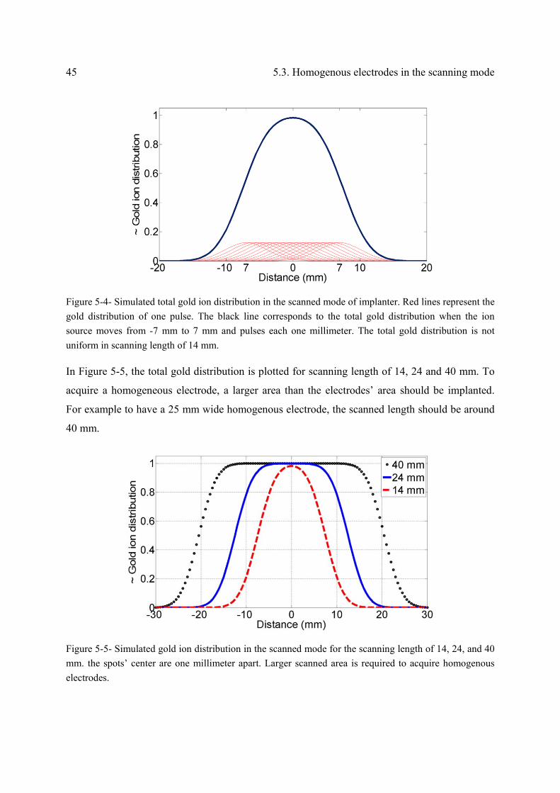
45 5.3. Homogenous electrodes in the scanning mode
Figure 5-4- Simulated total gold ion distribution in the scanned mode of implanter. Red lines represent the
gold distribution of one pulse. The black line corresponds to the total gold distribution when the ion
source moves from -7 mm to 7 mm and pulses each one millimeter. The total gold distribution is not
uniform in scanning length of 14 mm.
In Figure 5-5, the total gold distribution is plotted for scanning length of 14, 24 and 40 mm. To
acquire a homogeneous electrode, a larger area than the electrodes’ area should be implanted.
For example to have a 25 mm wide homogenous electrode, the scanned length should be around
40 mm.
Figure 5-5- Simulated gold ion distribution in the scanned mode for the scanning length of 14, 24, and 40
mm. the spots’ center are one millimeter apart. Larger scanned area is required to acquire homogenous
electrodes.

Chapter 5 Compliant electrodes by low energy ion-implantation 46
In the presented simulation, the sputtered ion-dose from the source is assumed constant over the
scanning period. However, I have observed that the ion-dose degrades as the source wears
leading to variation in the ion-dose in implantation cycles with large scanning area or high
number of pulses, making it more complicated to calibrate the implanter to pattern homogeneous
electrodes. The ultimate calibration of the implanter can be achieved by real-time monitoring the
sputtered ion-dose from the beam, inside the chamber, and developing a mechanism to
compensate the dose degradation for example by moving the source.
5.4. Miniaturized ion-implanted compliant electrodes
There is a linear correlation between the ion dose and the number of implantation arc pulses for
the mm scale electrodes, which is no more valid for the microelectrodes and a new calibrations
curve is required depending on the thickness of the shadow mask and the electrode size. Due to
geometrical effect of the shadow mask and charge trapping during the implantation, the aspect
ratio of the mask affects the ion dose implanted in the elastomer. During the implantation the
mask is negatively charged as it is connected to the negative bias voltage and therefore, the
mask’s walls attract the positive gold ions reducing the dose of the gold ions passing through. A
100 µm thick shadow mask with 4 different openings is used to pattern 500 µm, 200 µm, 100
µm, and 50 µm wide electrodes by ion-implantation with the energy of 5 keV shown in Figure
5-6 (a). Patterning all the electrodes in one implantation cycle eliminates the possible variation in
ion-dose in different batches due to the gold source wear. To facilitate measuring the resistance
of the electrodes, a thin layer of gold is sputtered on both ends of the electrodes. Resistances of
the electrodes are measured and the corresponding resistivity is calculated and listed in Figure
5-6 (b). The resistivity of the 100 µm wide electrodes is two orders of magnitude larger than the
200 µm and 500 µm wide electrodes.

47 5.4. Miniaturized ion-implanted compliant electrodes
Figure 5-6- (a) schematic drawing of the ion-implanted electrodes with different widths through a shadow
mask. Two contact pads are sputtered at the both ends of the electrodes for ease of measurement of the
resistance. (b) Resistance and the calculated resistivity of the ion-implanted electrodes for different widths
are listed. The resistivity of the 100 µm wide electrodes is two orders of magnitude larger than the 200
µm and 500 µm wide electrodes.
The gold atoms in 500 m, 100 m and 50 m wide ion-implanted electrodes are detected with
an Energy Dispersive X-ray Spectroscopy (EDS) in an Environmental Scanning Electron
Microscope (ESEM) and mapped in Figure 5-7*. The impact of the shadow mask on the
electrodes is significant for aspect ratios below one; the gold concentration decreases and the
electrodes become non-homogenous as more ions pass and accumulate in the center.
* Thanks to Dr. Massoud Dadras from center of microscopy and nanoscopy at CSEM for his help in the EDS measurement

Chapter 5 Compliant electrodes by low energy ion-implantation 48
Figure 5-7- EDS mapping of amount of gold atoms in the ion-implanted electrodes vs. position from the
center of the line. The ion-implantation is performed through 100 m thick shadow mask of width 500
m, 100 m and 50 m. The aspect ratio of the mask affects the maximum concentration: if the aspect ratio of the shadow mask is less than one, a significant portion of the ion beam no longer reaches the PDMS.
In principle, there is no limitation in down scaling the ion-implanted electrodes. It is only
required to use a shadow mask thinner than the size of the electrode to minimize its impact on
the homogeneity and ion-dose. In this thesis, I have patterned compliant electrodes for DEAs as
small as 100 µm wide electrodes using a 50 µm thick shadow mask. Since the masks are cut by a
laser cutter on a steel plate, it is not technically feasible to pattern smaller than 100 µm wide
electrodes on thinner than 50 µm thick shadow masks. To pattern smaller electrodes, it is
recommended to pattern photoresist on the silicone as a mask or to fabricate shadow masks using
SOI wafer and dry etching.
5.5. Energy of ion-implantation
Using a lower bias voltage for the implanter decreases the energy of the ions implanted in the
PDMS. This reduces the charging of the mask and therefore, its impact on the implanted
electrodes. To pattern 100 µm wide electrodes with a resistivity of 5 kΩ/square with the same
shadow mask, 800 pulses are required at the energy of 5 keV and 450 pulses are sufficient at the

49 5.5. Energy of ion-implantation
energy of 2.5 keV. Moreover, as previously shown by Niklaus et al., decreasing the ions energy
decreases the stiffening impact of the electrodes on the elastomer, shown in Figure 5-8 [101].
Figure 5-8- (a) Stiffening impact of ion-implantation on PDMS membranes at different ion-energies. The lower energies have a lower impact on the stiffness of the elastomer. (b) Resistance of the ion-implanted PDMS at different ion-energies, showing that decreasing the ion-energy from 5 to 2.5 doesn’t influence the correlation between the dose and the resistance [101].
I also performed a quick test to verify this; three electrodes are patterned at ion-energies of 5
keV, 2.5 keV and 0 keV with about 400 pulses. The electrodes are highly conductive and the
resistance is about 33 Ω on a 1 mm diameter electrode. The Young’s modulus of the implanted
PDMS is then measured using a bulge test setup [96]. Young’s modulus of pristine PDMS made
of Dow corning Sylgard 186 with 1:10 mixing ratio is 1.4 MPa. The Young’s modulus of the
elastomer implanted with the ion energy of 2.5 keV is half of the one implanted at the energy of
5 keV. At lower ion-energy the size of gold clusters inside the PDMS are smaller decreasing the
stiffening impact of the gold-PDMS composite on the elastomer [101]. It is worth to mention that
when no voltage is applied to the substrate, the ions are not penetrating the elastomer and are
mostly coating the surface forming a thin layer leading to a higher stiffness, as listed in Table 5-1.
Table 5-1- The stiffening impact of the ion-implanted electrodes on the elastomer at different ion-
energies. The elastomer is made of Sylgard 186 with mixing ratio of 1:10 with 24 µm thickness.
Pristine Implanted
Ion-Energy -5 keV -2.5 keV 0 keV
Y (MPa) 1.4 1.7 6.8 3.5 8.8
R (ohm) 215 33 33 33
Pulses 360 440 400 400

Chapter 5 Compliant electrodes by low energy ion-implantation 50
To pattern compliant electrodes with minimum stiffening impact on the elastomer and
conductive enough to bring and remove the charges for dielectric elastomer actuators, a dose
slightly higher than the percolation threshold should be chosen. In this case, the conductivity of
the electrodes is at the order of 1 k/square and the Young’s modulus of PDMS is increased
about 40%. As listed in Table 5-1, the Young’s modulus is only increase 21% when the
resistivity of the electrode is 215 k/square at the ion energy of 5 keV.
5.6. Conclusion
I have shown how to pattern homogenous long narrow compliant electrodes for DEAs using low
energy ion-implantation.
1) Simulating the ion-beam distribution of our implanter with a Gaussian distribution, it
demonstrated that at least 40 mm long line should be scanned to acquire uniform ion-dose on a
25 mm long electrode.
2) Impact of the shadow mask on the ion-dose on the patterned electrodes is investigated using
Energy Dispersive X-ray Spectroscopy (EDS). Mask thickness should be smaller than the
electrode’s size to minimize the shadowing effect and charge trapping the mask.
3) There is no limit in down scaling the electrode’s size. Only a thin enough shadow mask is
required.
4) Decreasing the ion-energy to 2.5 keV, the charge trapping in the mask considerably decreased.
5) Decreasing the ion-energy to 2.5 keV minimized the stiffening impact of the ion-implantation
on the elastomer.
The ion-implantation is employed to pattern the compliant microelectrodes for the dielectric
elastomer microactuators discussed in the next chapter.

Chapter 6 Generation I: Pyrex bonded µDEAs
6.1. Summary
This chapter focuses on the first generation of DEA microactuators (µDEAs) for mechanical
stimulation of single cells. An array of 72 100 µm x 200 µm electroactive polymer actuators
which expand uniaxially when a voltage is applied is developed. The device is fabricated by
patterning compliant microelectrodes on both sides of a 30 µm thick polydimethylsiloxane
(PDMS) membrane, which is bonded to a Pyrex chip with 200 µm wide trenches. Low-energy
metal ion-implantation is used to make stretchable electrodes and I demonstrate here the
successful miniaturization of such ion-implanted electrodes. The top electrode covers the full
membrane area, while the bottom electrodes are 100 µm wide parallel lines, perpendicular to the
trenches. Applying a voltage between the top and bottom electrodes leads to uniaxial expansion
of the membrane at the intersection of the bottom electrodes and the trenches. To characterize the
in-plane strain, an array of 4 µm diameter aluminium dots is deposited on each actuator. The
position of each dot is tracked, allowing displacement and strain profiles to be measured as a
function of voltage. The uniaxial strain reaches 4.7% at 2.9 kV with a 0.2 s response time,
sufficient to stimulate mostly stiff cells such as bone cells with relevant biological strains and
frequencies. The design principle, microfabrication, and characterization of this generation will
be discussed here, which is also published in Journal of Micromechanics and Microengineering
2012, 22 (4), 045020. This article was selected by IOP publisher, JMM highlights and research
highlights of EPFL.

Chapter 6 Generation I: Pyrex bonded µDEAs 52
6.2. Actuation principle
The micro-actuator consists of a 30 m thick non-prestretched PDMS membrane (Sylgard 186)
with a 100 m wide compliant microelectrode on one side and a blanket compliant electrode on
the other side, as schematically shown in Figure 6-1. To have uniaxial in-plane strain when a
potential difference is applied between the blanket electrode and the microelectrode, the y-axis
displacement is limited by bonding the membrane to a Pyrex chip with a 200 m wide and 100
m deep trench, which is perpendicular to the microelectrode. The actuator is thus at the
intersection of the microelectrode and the 200 m channel over which the electrostatically
compressed membrane is free to expand in-plane.
Once the actuator is fabricated, a single cell will be attached on the actuator and stretched
uniaxially when the membrane expands over the trench. This is feasible by either patterning cell
adherent extracellular-matrix protein on the actuator or patterning protein repellent co-polymers
such as poly-l-lysine grafted polyethylene glycol (PLL-g-PEG) on the surface except on the
actuators by micro-contact printing [121, 122].
The cells will be immersed in conductive cell culture medium, which will be grounded with the
top electrode and the high voltage is applied to the bottom microelectrodes. This configuration
ensures that the electric field reaching the surface by fringe field through the air is eliminated and
the cells’ behavior is only affected by the mechanical field as the cells are sensitive to the electric
fields of higher than 1 V/cm [123].

53 6.3. Design considerations
Figure 6-1- (a) Schematic of one cell-stretcher, consisting of a 30 m thick PDMS membrane bonded on
a Pyrex chip with a 200 m wide trench. The red line represents the 100 m wide ion-implanted gold electrode on the bonded side (bottom) of the membrane and there is a blanket ion-implanted electrode on top (brown rectangle). (b) Cross section view (section A-A) of the device showing a single cell adhered on top of the actuator at the off state. (c) Actuated state of the device, explaining that when a high voltage is applied to the bottom microelectrode, the membrane compresses in thickness and expands uniaxially over the trench. Thus, the actuator is at the intersection of the microelectrode and the trench. (d) Cross-section view of the actuated state of the cell-stretcher, showing that a single cell attached on the actuator is stretched with the substrate.
6.3. Design considerations
Dielectric elastomer actuators are particularly well suited to cell stretching devices as they can be
made on soft biocompatible silicone membranes on which cells are cultured. Besides the cells
are much softer (Young’s modulus 0.2-40 kPa [124]) than the polymer membranes used in EAPs
(Young’s modulus of order 1 MPa), thus imposing a negligible effect on the actuation strain of
the actuators.

Chapter 6 Generation I: Pyrex bonded µDEAs 54
The size of the actuator is defined by the width of the microelectrode and the width of the trench.
The actuator size has a minor impact on the actuation strain based on my finite element analysis
published in SPIE Proceeding in 2010 [125]. The actuator’s size is designed close to the size of
the single cells, which vary from 10 m to 50 m depending on the cell type. One limiting factor
in downsizing the microactuator is the aspect ratio of the shadow mask used to pattern the ion-
implanted electrode as it affects the concentration of the gold dose for the aspect ratios of less
than 1, as discussed in the last chapter. Since I am using 50-70 m thick shadow masks, I have
chosen 100 m wide ion-implanted electrodes. My FEM based geometrical optimization has
shown that the actuators with wider trenches have higher actuation strain at a certain voltage
[125]. That’s why, 200 m wide trenches are selected for the actuators.
As discussed in section 4.4, pre-stretching the membrane modifies the performance of the
dielectric elastomer actuators by increasing the breakdown electric field and hindering the pull-in
instability [60, 95, 106, 126, 127]. However, I have noted a low yield in bonding of the
prestretched membranes (>20%) to the Pyrex chips by oxygen plasma activation. Therefore,
here, I use a non-prestretched membrane for the actuators. In the next generation of actuators in
next chapter, I make benefit of the advantages of prestretching the membrane to generate up to
80% planar actuation strain.
6.4. Finite Element Analysis
Numerical analysis of one single actuator is carried out in ANSYS [128] to study strain and
deflection of the device vs. voltage and geometry, and to predict the critical buckling voltage
beyond which uniaxial strain is no longer possible. I have not included the geometrical
optimization of the actuator performed by Finite Element Method (FEM) model and published in
SPIE proceeding [125]. In this thesis, I have performed more accurate simulations on the
optimized geometry using similar material properties as the fabricated device. The comparison of
the numerical and experimental results is discussed in section 6.6.2.
A coupled field element Solid 226 is used to mesh 1 mm x 1 mm elastomer with a 100 m x 200
m actuator at the center. The geometrical dimensions and the material properties used in the
simulation are listed in table 6-1, which are close to the fabricated actuators in order to compare
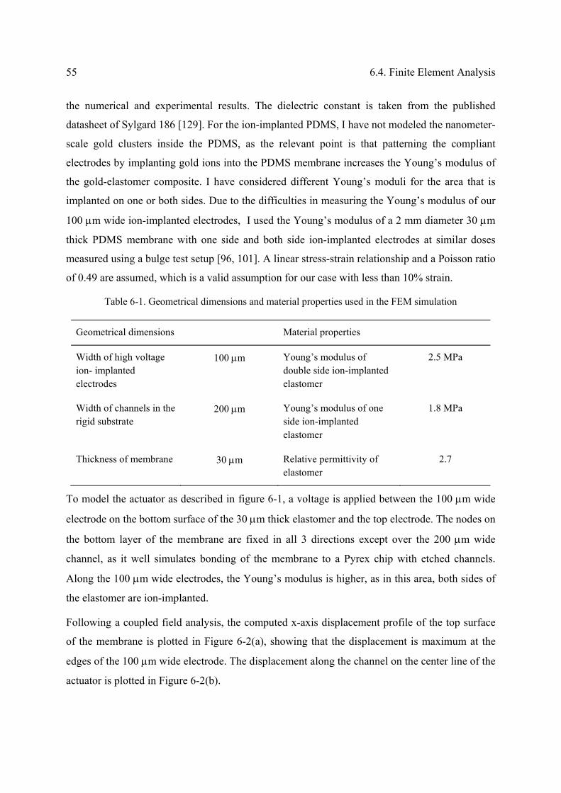
55 6.4. Finite Element Analysis
the numerical and experimental results. The dielectric constant is taken from the published
datasheet of Sylgard 186 [129]. For the ion-implanted PDMS, I have not modeled the nanometer-
scale gold clusters inside the PDMS, as the relevant point is that patterning the compliant
electrodes by implanting gold ions into the PDMS membrane increases the Young’s modulus of
the gold-elastomer composite. I have considered different Young’s moduli for the area that is
implanted on one or both sides. Due to the difficulties in measuring the Young’s modulus of our
100 m wide ion-implanted electrodes, I used the Young’s modulus of a 2 mm diameter 30 m
thick PDMS membrane with one side and both side ion-implanted electrodes at similar doses
measured using a bulge test setup [96, 101]. A linear stress-strain relationship and a Poisson ratio
of 0.49 are assumed, which is a valid assumption for our case with less than 10% strain.
Table 6-1. Geometrical dimensions and material properties used in the FEM simulation
Geometrical dimensions Material properties
Width of high voltage ion- implanted electrodes
100 m Young’s modulus of double side ion-implanted elastomer
2.5 MPa
Width of channels in the rigid substrate
200 m Young’s modulus of one side ion-implanted elastomer
1.8 MPa
Thickness of membrane 30 m Relative permittivity of elastomer
2.7
To model the actuator as described in figure 6-1, a voltage is applied between the 100 m wide
electrode on the bottom surface of the 30 m thick elastomer and the top electrode. The nodes on
the bottom layer of the membrane are fixed in all 3 directions except over the 200 m wide
channel, as it well simulates bonding of the membrane to a Pyrex chip with etched channels.
Along the 100 m wide electrodes, the Young’s modulus is higher, as in this area, both sides of
the elastomer are ion-implanted.
Following a coupled field analysis, the computed x-axis displacement profile of the top surface
of the membrane is plotted in Figure 6-2(a), showing that the displacement is maximum at the
edges of the 100 m wide electrode. The displacement along the channel on the center line of the
actuator is plotted in Figure 6-2(b).

Chapter 6 Generation I: Pyrex bonded µDEAs 56
Figure 6-2- (a) Simulated x-axis displacement profile of the top surface of a 30 m thick membrane when 2.6 kV is applied between the electrodes. (b) Simulated x-axis displacement along the channel along the centerline of the actuator (red dot-dashed line in the right picture). The x-axis displacement is zero at the center of the actuator and increases linearly toward the edges of the electrodes.
The computed x-axis strain profile is plotted in Figure 6-3(a), showing that the x-axis strain is
maximum and constant over the actuator. The strain along the centerline of the actuator is plotted
in Figure 6-3(b), showing that 4.1% strain is predicted at 2.6 kV using the material properties
listed in Table 6-1. Having a constant strain on an area of 100 m2 on the actuator ensures that a
cell will sense a uniform strain.
Figure 6-3- (a) Simulated x-axis strain profile of the actuator, when 2.6 kV is applied between the
electrodes. The strain is constant over the actuator i.e. over the intersection of the 100 m wide electrode
and the 200 m wide trench. (b) Computed x-axis strain plotted on the centerline of the actuator, showing

57 6.5. Microfabrication
that the strain is maximum and constant on the actuator. 4.1% strain is obtained using the material properties listed in table 6-1.
The actuation strain of the dielectric elastomer actuator can be increased until it fails due to
breakdown of the dielectric, instability mode, rupture of the membrane or loss of tension. In this
case, the buckling threshold is added to the list too. Since the membrane is not pre-stretched, the
actuator buckles at a certain strain, when the compressive force in the non-implanted membrane
exceeds the buckling limit. A linear buckling analysis is performed to estimate the critical
buckling voltage for these actuators. The first buckling mode is shown in Figure 6-4, which
occurs at 3.97 kV. The computed actuation uniaxial strain before buckling at 3.8 kV is 12%
which is a promising value that can cover the desired strain for stimulating most cell types. The
same buckling mode is also experimentally observed but at lower strain values, which is
discussed in section 6.6.2.
Figure 6-4- Simulated first buckling mode of a 100 m x 200 m actuator on a 30 m thick PDMS membrane at 3.97 kV. The contour legend shows the relative displacement of the mode shape.
6.5. Microfabrication
A schematic diagram of an array of 72 microactuators composed of a 30 m thick PDMS
membrane with 9 microelectrodes bonded on a Pyrex chip with 8 trenches is shown in Figure
6-5. The device is electrically grouped into three groups of 24 actuators, to allow three different
frequencies or amplitudes on a given chip. Electrical contact to the bottom ion-implanted lines is

Chapter 6 Generation I: Pyrex bonded µDEAs 58
an important aspect, and the Pyrex chip serves both as a support for the EAP device, but also as a
support for thicker gold pads to which wirebonded connections can be made. As the actuators
operate independently, their quantity in the array can easily be increased by adding more
microelectrodes on the membrane or more channels in the Pyrex chip, without influencing the
actuation strain of individual actuators.
Figure 6-5- Array of 72 microactuators
The fabrication process of the array of uniaxial cell stretchers is shown in Figure 6-6. The main
fabrication steps are summarized in this paragraph, and then discussed below. First, Pyrex chips
with patterned gold electrodes and etched 200 m wide trenches are fabricated. Then, a 30 m
thick PDMS membrane is prepared and 100 m wide compliant electrodes are patterned on it
with low-energy ion-implantation. Finally, the membrane is bonded to the Pyrex chip and a
blanket electrode is ion-implanted on the top surface.

59 6.5. Microfabrication
Figure 6-6- (a) Gold electrodes are patterned on a Pyrex substrate and 200 m wide 100 m deep trenches
are etched by powder blasting. (b) 30 m thick PDMS membrane is casted over a support film (polyimide, Upilex®-50S). (c) The gold ions are selectively implanted through a shadow mask in our ion-implanter at the energy of 2.5 keV and the gold contacts at the end of the implanted lines are deposited. (d) A thin layer of PDMS is casted over the main film and cured while the contact pads are protected. (e) The PDMS membrane is chemically bonded to the substrate. (f) The support film is removed and the top layer of the membrane is ion-implanted and the top gold contacts are deposited by sputtering.
6.5.1. Fabrication of Pyrex chips with patterned gold electrodes and etched
channels
In order to confine the in-plane expansion of the membrane along one axis, the membrane is
bonded to a rigid substrate with channels inside. Previously, I have reported using a 2 mm thick
PDMS (Sylgard 184) substrate with 100 m wide channels, which were patterned by molding
the uncured PDMS over a SU-8 mold [125]. In this design, I have used 500 m thick Pyrex chips
with 200 m wide trenches. Pyrex is much stiffer than PDMS and it is easier to make reliable
electrical contacts on it.
The Pyrex chips are fabricated at the wafer level; first, gold electrodes are patterned on a 500 m
thick Pyrex wafer using a lift off process with a negative photoresist (AZ 5214). The thickness of
the evaporated gold is 200 nm on a 20 nm thick chromium adhesion layer. This thickness is

Chapter 6 Generation I: Pyrex bonded µDEAs 60
sufficient to connect to wires using wire bonding or low temperature soldering. Then, 200 m
wide and 100 m deep channels are etched in the wafer by powder blasting [130]. Powder
blasting leads to sidewalls with an approximately 15° angle, with a roughness of order 0.8 m.
Finally, the wafer is diced to 20 mm x 20 mm chips.
The gold electrodes patterned at two edges of the Pyrex chip will serve to contact the
microelectrodes patterned on the bottom (bonded) layer of the membrane. The Pyrex chip is
slightly larger than the membrane so that the gold electrodes on the Pyrex can be easily contacted
after assembly.
6.5.2. Fabrication of 30 m thick PDMS membrane
The two components of Sylgard 186 from Dow Corning are mixed with 10:1 weight ratio as
recommended by the manufacturer and diluted with iso-octane (PDMS: Solvent 10:9 weight) in
order to decrease its viscosity. The mixture is degassed for 30 minutes until all the trapped air
bubbles are removed. A universal applicator ZUA 2000 from Zehntner GmbH Testing
Instruments is used to cast the PDMS mixture on a 55 m thick polyimide film as a support. The
parameters are adjusted to have 30 m thick membranes. The film is cured at 100⁰C for 40
minutes in the oven. The PDMS membrane is then cut to 17 mm x 17 mm pieces.
6.5.3. Compliant electrodes by low energy ion-implantation
Based on the main points discussed in the last chapter for patterning compliant electrodes with
ion-implantation, to decrease the mask’s effect on the ion dose, 70 m thick shadow masks are
used to pattern 100 m wide electrodes on a 17 mm x 17 mm PDMS film. The implantation
energy is decreased to 2.5 keV as it reduces the attraction of the positive gold ions to the
negative mask walls. With these modifications, half of the previous implantation pulses are
sufficient to pattern electrodes at a dose slightly higher than the percolation threshold. In this
case, the conductivity of the electrodes is at the order of 1 k/square and the Young’s modulus
of PDMS is increased about 40%. Afterward, gold electrodes with the same shape as the ones on
the Pyrex chip are patterned at the ends of the ion-implanted electrodes using a sputter coater
through a shadow mask. After bonding the membrane to the Pyrex chip, the patterned gold
electrodes on the chip create a conducting path to access the bottom implanted electrodes.

61 6.5. Microfabrication
6.5.4. Bonding
A high bond strength between the PDMS membrane and the Pyrex chip is required at the edges
of the actuators to ensure reliable operation. Both pristine PDMS as well as the ion-implanted
electrodes should bond to the Pyrex chip. Traditional plasma O2 bonding methods do not activate
the surface of gold ion-implanted PDMS and hence it is not effective for to bond Pyrex to ion-
implanted PDMS bonding. Other techniques have been reported to bond two PDMS microfluidic
chips, such as using uncured PDMS or curing agent of Sylgard 184/186 as an adhesive [131-
133]. These techniques do not bond the PDMS to Pyrex as they only react with the uncured
polymeric chains of PDMS and not Pyrex. My solution is to cast a thin layer of uncured PDMS
over the ion-implanted film and let it cure. This thin PDMS layer is well bonded to the ion-
implanted PDMS, and the non-implanted PDMS layer on top bonds to the Pyrex chip by Plasma
O2 activation (See figure 6-6(d)). As this “passive” layer reduces the strain, it is important to
minimize its thickness and stiffness, and hence the two components of Sylgard 186 are mixed
with 20:1 weight ratio as this makes a much softer film [134] and the PDMS is diluted with two
times more solvent (PDMS: Solvent 1:2 weight) as it results to a thinner film. While casting the
uncured PDMS with the applicator, the contact pads are protected with a 25 m thick Teflon film
(PFA from Dupont). The thin layer is cured at 65⁰C for 4 hours. It is important to keep the curing
temperature lower than 80⁰C to not lose the conductivity of the ion-implanted electrodes on the
PDMS due to different thermal expansion coefficients between gold and PDMS. The resulting
“passive” PDMS layer is 2.5 m and it is well bonded to the main ion-implanted PDMS
membrane.
The pristine top of the “passive” film is then bonded to the Pyrex chip by exposing both of them
to oxygen plasma (15 s at 400 W and 2.45 GHz, with an O2 flow of 400 sccm and at a pressure
of ~500 mtorr). Before bonding, the Pyrex chips are washed with iso-propanol and then
deionized water and dried completely with nitrogen gas. Without using the intermediate layer
and by directly bonding the ion-implanted PDMS membrane to the Pyrex chip by plasma O2, the
100 m wide electrodes do not bond to the Pyrex chip. This results in unstable actuation strain
and lower buckling voltages, reducing the maximum achievable in-plain strain by 50%, as will
be discussed in section 6.6.5.

Chapter 6 Generation I: Pyrex bonded µDEAs 62
At the final step of fabrication, the polyimide support film is removed and the compliant
electrodes on top are patterned by ion-implantation and two small gold contact pads are
deposited by a sputter coater. To characterize the device, without the cell culture medium, a
blanket electrode is implanted on top, otherwise the conductive liquid will be used as the ground
electrode, avoiding the slight stiffening effect of the top electrode.
Figure 6-7(a) shows a fabricated device consisting of 72 100 m x 200 m actuators in three
independently controlled groups. Each group of 24 actuators is contacted by one trident-shape
electrodes. The second trident-shape electrode is used to measure the resistance of the 100 m
wide ion-implanted wires to characterize the implantation dose. Each of the three groups can be
actuated with different voltages and frequencies making it possible to stimulate different groups
of cells with various strains in the same cell culture. The chip holder shown in figure 6-7(b) is
designed to allow electrical contacts and safe operation when the top of the chip is immersed in
conductive cell culture medium.
Figure 6-7- (a) Fabricated array of 72 100 m x 200 m dielectric actuators. (b) Device in its holder designed for ease of liquid handling. The green wires are connected to the ground electrode on top and the red ones are connected to the high voltage to the bottom electrodes.
6.6. Characterization
The static and dynamic uniaxial strain profile of the actuators is measured optically as a function
of the drive voltage. The uniformity of the actuators in the array is verified by comparing the
actuation strain of 15 out of 24 actuators in one group of a device. The dynamic behavior of the
1cm (a) (b)

63 6.6. Characterization
actuators is studied, actuating them with square signals at frequency of 0.5 Hz and 1 Hz, showing
that the response time of the actuator is sufficient for stimulating the cells with relevant
biological frequencies. The measured data match well with the FEM predictions.
The conventional method to measure the deflection of dielectric elastomer actuators is to track
the edges of the electrodes before and after applying the voltage. In our actuators, detecting the
edges of the ion-implanted electrodes, which are at the bottom layer of the membrane covered
with a blanket ion-implanted electrode on top of the membrane does not lead to accurate
measurements specially for strain levels lower than 10%. To accurately characterize the in-plane
strain of the actuated devices, an array of 100 nm thick 4 µm diameter aluminum dots, are
deposited through a stencil mask on each actuator* (Figure 6-8). The holes in the stencil are
etched in a 500 nm thick silicon nitride membrane that enables depositing micrometer features
using a thermal evaporator [44-45]. The stencil mask is carefully aligned with the device to have
an array of dots on each actuator, as seen in Figure 6-8(a). The dots are spaced 14 m apart and
cover an area of 500 m x 400 m to monitor the deflection of the membrane on and around the
100 m x 200 m actuators.
Figure 6-8- (a) Optical micrograph of four 100 m x 200 m actuators. Arrays of 4 m diameter aluminum dots are deposited on the actuators through a stencil mask. (b) SEM micrograph of four 100 nm thick deposited aluminum dots.
It is important that the aluminum dots do not stiffen the membrane and reduce the actuation. To
gauge this, I have performed a static finite element analysis in ANSYS to compute the effect of
* Thanks to Dr. Oscar Vazquez Mena previous member of LMIS1 lab at EPFL for fabrication of the stencils.

Chapter 6 Generation I: Pyrex bonded µDEAs 64
dots on the Young’s modulus of the PDMS membrane: A clamped plate is subjected to a static
tensile force and the deformation of the tip is compared between the plates with or without the
aluminum dots, as shown in Figure 6-9. Ratio of the tip displacements in patterned and pristine
plates is inversely proportional to the ratio of their Young's modulus. The effective Young’s
modulus is increased by 1% when the 4 m diameter dots are spaced 14 m, and by 6.7% when
the dots are spaced 9 m apart.
Figure 6-9- Simulated longitudinal deformation of a clamped PDMS elastomer with/without patterned
aluminum dot array subjected to a tensile force. The tip displacement is inversely proportional to the
Young's modulus of the elastomer. (a) Pristine PDMS plate. (b) 4 µm diameter, 100 nm thick Aluminum
dots are patterned on the PDMS membrane in array with 14 µm spacing. (c) The Aluminum dots are
spaced 9 µm apart from each other.
The dots are only deposited to characterize the strain of the device and will not be deposited on
the devices made for cell stretching experiments.
6.6.1. Image processing
An image is recorded at each voltage step before and after actuation through a microscope at 20
times magnification (Figure 6-10(a)). Based on the clear contrast between the dots and the
background, by transferring the image to a binary image, each dot corresponds to a distinct
particle (Figure 6-10(b)). X and y coordinates of center of mass of the particles are saved in an
array using Labview Vision software. For each image, the program randomly stores the position
of the particles in an array. To be able to compare the position of the dots before and after
actuation, position of the particles are sorted and stored into matrices of Xi(In x Jm) and Yi(In x Jm)
for the image at zero voltage and into Xf(In x Jm) and Yf(In x Jm) for the image after actuation. In
and Jm are the number of dots in x and y directions. In this case, each index(i, j) corresponds to a
distinct particles. After organizing the particles, subtracting the Xf and Xi matrices gives the

65 6.6. Characterization
deformation in the x direction and subtracting the Yf and Yi matrices gives the deformation in the
y direction. To calculate the strain, the deformation field should be differentiated. The finite
difference method to numerically differentiate the deformation matric is not precise as the dots
are not tightly enough spaced to prevent stiffening of the membrane. That’s why, I have first
smoothed the deformation curve for each row of dots by fitting a 10th order polynomial and then
differentiated the fitted curve to calculate the strain in that row. To calculate the strain in the y
direction, the process is repeated for a column of the dots.
Figure 6-10- (a) An image is recorded at each voltage step through a microscope at 20 times
magnification. (b) The image is transferred to a binary image, where each dot represents a particle.
It is possible that a dot is not well deposited due to a defect in the stencil mask or a dust particle
and consequently, the detected particles cannot fill a two dimensional matrix (Figure 6-11). This
should be compensated so that the deformation and the strain fields can be calculated.
Figure 6-11- Due to a defect or a dust particle, it is possible to not detect all the dots. (a) Recorded image.
(b) The transferred binary image.

Chapter 6 Generation I: Pyrex bonded µDEAs 66
The program that I have written is fault tolerant; it identifies the undetected particle and
associates the average position of the adjacent particles to it, as shown in Figure 6-12. The circles
are the particles initially detected and the crosses represent the two dimensional mesh matric that
is built by estimating the position of the undetected particles from the adjacent particles. The
program covers for up to two adjacent undetected particles and also for the particles in the edges.
Figure 6-12- The black dots are the detected dots from Labview based image processing program. The red
crosses represent the two dimensional mesh that have replaced the undetected dots with the average of the
position of adjacent dots. The red points are then organized in a matric and used to calculate the
deformation and strain fields.
6.6.2. Static response
In Figure 6-13(a) the deflection profile of one actuator is plotted when a 2.6 kV dc voltage is
applied. In the contour plot, each node of the mesh represents one aluminum dot and the x-axis
displacement of the dot is mapped on the mesh. Figure 6-13(b) shows the displacement of the
dots along the channel on the centerline of the actuator. The displacement is zero at the center
and is increased linearly toward the edges of the electrodes to 2.2 m.

67 6.6. Characterization
Figure 6-13- (a) Measured deformation profile of one actuator, at 2.6 kV, derived by subtracting positions
of dots before and after actuation; Center of the actuator is at (0, 0). The actuator is 100 m x 200 m in a
device with 30 m thick Sylgard 186 membrane. The intermediate PDMS layer used for bonding is 3 m thick (Sylgard 186, mixing ratio 1:20, (PDMS: Solvent, 1:2)). (b) X-axis displacement profile of dots
along the channel on the centerline of the actuator (dashed line in (a)), showing 2.2 m symmetrical displacements at the edges of the electrode. The displacement shape matches very well the FEM results in Figure 6-2.
In order to calculate the x-axis strain, x-axis displacement along the x-axis is plotted for each
row of dots and smoothed. The smoothed curve is then differentiated and the strain is plotted in
the color map in Figure 6-14(a) for one actuator at 2.6 kV. The results confirm that the in-plane
strain exists along the electrode and reaches to the maximum over the channel on the actuator.
The strain variation at the center of the actuator is negligible (0.2%) for an area of 50 m2. It
means that a single cell attached on the center of the actuator will sense a constant strain. The x-
axis in-plane strain along the channel on the centerline of the actuator is plotted in Figure
6-14(b).
X (m)
Y(
m)
-300 -200 -100 0 100-200
-100
0
100
200
Dx
21.510.50
-0.5-1-1.5-2
(a) (b)

Chapter 6 Generation I: Pyrex bonded µDEAs 68
Figure 6-14- (a) Measured x-axis strain of a 100 m x 200 m actuator on the same device as in figure 6-13; Center of the actuator is at (0, 0). (b) Measured x-axis strain along the channel on the centerline of
the actuator at 2.6 kV. The in plane uniaxial strain at a 50 m2 area on the center of the actuator is 3.7% to 3.9%.
The numerical results of x-axis strain and x-axis displacement presented in Figure 6-2 and Figure
6-3 are in excellent agreement with the experimental results presented in Figure 6-13 and Figure
6-14 qualitatively and quantitatively, despite the uncertainty in the exact Young’s modulus of the
ion-implanted electrodes. There are some details such as the electric field spread through the air
in the channel and different Young’s modulus of the 3 m thick intermediate layer that are not
considered in the FEM model.
The actuation strain increases quadratically with the applied voltage as expected since the
electrostatic pressure is proportional to the square electric field (Figure 6-15). I achieved 4.7%
strain at a voltage of 2.9 kV before the membrane buckles and the actuation mode switches to
biaxial out of plane strain from uniaxial in-plane strain. The strain level of our device is
sufficient to mechanically stimulate most of cell types.
X (m)
Y(
m)
-200 -100 0 100-200
-100
0
100
200
Sx
3.532.5210
-200 -100 0 100-1
0
1
2
3
4
X (m)
Str
ain
x (%
)
(a) (b)

69 6.6. Characterization
Figure 6-15- Measured x-axis in-plane strain vs. drive voltage, showing the expected V2 scaling. A maximum strain of 4.7% is observed at 2.9 kV.
The critical buckling voltage varies from 3 kV to 4.5 kV for different fabricated devices
depending on their initial thickness and thickness of their passive layer. Besides, the internal pre-
stress caused during cross-linking of the main film or the passive layer influences the critical
buckling voltage, which is not considered in the FEM simulations. Due to this fact, the value of
the computed critical buckling voltage is not the same as the experimental buckling voltage and
the membrane buckles at lower voltages. Figure 6-16 demonstrates the measured buckling
profile of one of the devices at 4.5 kV using a white light interferometer (WYKO NT1100,
Veeco, USA). The membrane is squeezed along the electrode and buckled on the actuator at the
intersection of the electrodes and the channel. The intermediate layer for bonding on this device
is made of Sylgard 186 with mixing weight ratio (cross-linker: oligomers) of 1:13.5, which
explains the higher buckling voltage of this device compared to the device in Figure 6-15 with
mixing ratio of 1:20 for the bonding layer. However, the experimentally observed buckling mode
is the same as the computed mode shape (Figure 6-4). The ultimate failure of our dielectric
elastomer actuators based on non-prestretched membranes with strain of lower than 10 %, is due
to the electrical breakdown of the PDMS membrane.

Chapter 6 Generation I: Pyrex bonded µDEAs 70
Figure 6-16- Buckling profile of an actuator at 4.5 kV measured using white light interferometer. The
membrane is squeezed along the electrode and buckles at the intersection of the electrode and the channel.
The dots on the membrane are the aluminum dots patterned for in-plane strain measurements. The
intermediate layer for bonding of this device is made of Sylgard 186 with mixing ratio of 1:13.5.
To verify the uniformity of the actuation strain of the actuators on the array of one device, I
randomly tested 15 actuators in one of the three groups of the device at 2 kV. A histogram of the
measured strain is plotted in Figure 6-17, showing that 10 out of 15 actuators have the strain
between 1.9-2.15% and the strain of the other 5 actuators is 0.2% lower. Considering 0.1-0.2%
error in strain calculation of our image processing technique, I believe that this strain disparity is
very promising for an array of dielectric elastomer micro-actuators having polymers as their
main components that can have non-uniform stiffness/ thickness due to non-uniform cross
linking. Other sources of strain difference between multiple actuators in the array can be the
stiffness inconsistency of the ion-implanted electrodes or thickness variation of the passive
intermediate PDMS layer used for bonding.

71 6.6. Characterization
Figure 6-17- Histogram of x-axis strain of 15 out of 24 actuators of one group of the device at 2 kV,
showing consistent actuation strain over the multiple actuators. The actuator is 100 m x 200 m on a 25
m thick Sylgard 186 membrane. The intermediate PDMS layer used for bonding is 2.5 m thick (Sylgard 186, mixing ratio 1:20, 200% iso-octane solvent).
6.6.3. Dynamic response
The dynamic behavior of one actuator driven with a 2.6 kV square signal at 1 Hz and 0.5 Hz
using a high voltage amplifier (Model 609E-6 from TREK, Inc.) is shown in Figure 6-18. 25
frames per second are recorded with a Basler A622f camera connected to the microscope, and
the images are analyzed with our image processing program to characterize the actuation strain
over time. One of the images at zero voltage is used as the reference off state image to measure
the dots’ displacement of other images. The response time is 0.2 s, which is sufficient to actuate
the cells with relevant biological frequencies (0.05 Hz-5 Hz) [3]. The response time is limited
here by the electrical RC time constant of high resistive electrodes. There is a tradeoff between
the response time and the achievable strain of the actuators due to the inverse link between the
resistance and Young’s modulus of ion-implanted electrodes.
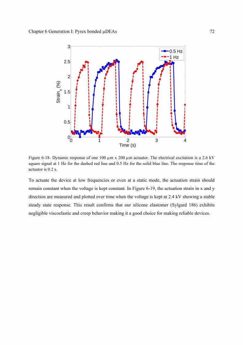
Chapter 6 Generation I: Pyrex bonded µDEAs 72
Figure 6-18- Dynamic response of one 100 m x 200 m actuator. The electrical excitation is a 2.6 kV square signal at 1 Hz for the dashed red line and 0.5 Hz for the solid blue line. The response time of the actuator is 0.2 s.
To actuate the device at low frequencies or even at a static mode, the actuation strain should
remain constant when the voltage is kept constant. In Figure 6-19, the actuation strain in x and y
direction are measured and plotted over time when the voltage is kept at 2.4 kV showing a stable
steady state response. This result confirms that our silicone elastomer (Sylgard 186) exhibits
negligible viscoelastic and creep behavior making it a good choice for making reliable devices.
0 1 2 3 40
0.5
1
1.5
2
2.5
3
Time (s)
Str
ain
x (%
)
0.5 Hz1 Hz

73 6.6. Characterization
Figure 6-19- The actuation strain in x and y directions over time when the voltage is kept at 2.4 kV.
6.6.4. Life time measurement
Cells regulate their biochemical responses over a time scale of a few minutes to a few hours for
periodic strains [2, 3]. I actuated our devices with a 2.6 kV square signal at 1 Hz for 130 minutes.
Every 10 minutes 100 frames, corresponding to 4 seconds of operation, are recorded and
analyzed. Figure 6-20 shows the actuation strain of an actuator at the beginning of the test, after
70 minutes and after 130 minutes. The strain level and the response time have not changed over
the test period. Lifetimes of more than 1.3 million cycles have been reported for buckling-mode
DEA actuators made from non-prestretched silicone membranes with ion-implanted electrodes
operated at 1.5 kV [135]. In our group, tunable lenses with ionic liquid electrodes have also been
successfully operated for thousands of cycles. However, to operate the device in salt water
(similar to the cell culture medium) it will be necessary to seal the PDMS membrane, as it is
porous and absorbs the ions, leading to breakdown after half an hour periodic actuation (at 1 Hz).
One approach is to deposit a 100 nm thick Parylene layer on the PDMS membrane and later etch
this layer away with plasma O2. It has been reported that this procedure caulks the PDMS pores
and thus seals the membrane minimized impact on stiffness [136]. Another approach is to add
another passive elastomeric layer on top of the actuators to increase the life time in conductive

Chapter 6 Generation I: Pyrex bonded µDEAs 74
liquid environment. However, adding a passive elastomeric layer on top or coating the elastomer
with a thin Parylene layer decreases the actuation strain. To fulfill the requirements for a reliable
cell stretcher device, operating in conductive cell growth medium for hours, it is required to
develop actuators with higher than 40 % actuation strain. In this case, even if half the actuation
strain is sacrificed by the passive layer, the device can stretch the cells with up to 20% strain. In
the next chapter, I will discuss development of actuators with actuation strain of up to 80%.
Figure 6-20- Life time measurement: Actuation strain of a 100 m x 200 m actuator with an excitation voltage of 2.6 kV square signal at 1 Hz frequency is measured initially, after 4200 cycles and after 7800 cycles. The strain level is reproducible within 0.2 % strain.
6.6.5. Direct bonding
In this section, I briefly discuss the reason behind the developed bonding technique, where a 2-3
µm thick PDMS layer is used between the ion-implanted electrodes and the Pyrex chip, as
illustrated in Figure 6-7. When no intermediate layer is used, the ion-implanted electrodes do not
bond to the Pyrex chip by plasma O2 activation. This leads to lower in-plane actuation strain as
the membrane deforms out of plane and buckles inside the channels. Figure 6-21 shows the
actuation strain in both x (along the channel) and y direction for a device with identical
fabrication parameters as the device shown in Figure 6-15, except that no intermediate layer is
0 1 2 3 40
0.5
1
1.5
2
2.5
3
Time interval (s)
Str
ain
x (%
)
0 cycles4200 cycles7800 cycles

75 6.6. Characterization
used to bond the ion-implanted electrodes to the Pyrex chip. The device exhibits lower actuation
strain and buckles at 2.6 kV, where the actuation strains in x and y directions are equal.
Figure 6-21- The strain along the x and y directions when the applied voltage is incremented. The
membrane buckles at 2.6 kV as the strain in x and y direction are equal. The in-plane actuation strain
before buckling is 50% lower for this device (without the intermediate layer for bonding) compared to the
device in Figure 6-15 (with the intermeidate boding layer with mixing ratio of 1:20).
Figure 6-22, depicts the out of plane deformation of the actuator measured with white light
interferometer. The actuator buckles inward the channel at 2.5 kV and deforms more out of plane
at higher voltages. Although the actuator has not broken, the out of plane mode of actuation is
not of our interest for stretching cells. When the membrane is not well bonded on the electrodes
to the Pyrex chip, the membrane slips inside the channel and deforms out of plane rather than in-
plane along the channel.

Chapter 6 Generation I: Pyrex bonded µDEAs 76
Figure 6-22- The out of plane deformation of an actuator when the ion-implanted electrodes are not well
bonded to the Pyrex chip. (a) at 2.5 kV, (b) at 3 kV.
The plotted actuation strains in Figure 6-21 are measured after 2 seconds that the voltage is
applied. However, the actuation strain is not stable over time when the voltage is kept on. The
time response of the maximum displacement along the channel is measured when the voltage is
kept at 1.5 kV and plotted in Figure 6-23. The actuation x-axis deformation vanishes completely
after one minute the voltage is on. Since the membrane is not well bonded along the electrodes to
the Pyrex chip, the membrane de-bonds with time and deforms out of plane inward the channels.
Figure 6-23- Maximum displacement along the channel when the voltage is kept on at 1.5 kV for 60
seconds. The in-plane strain relaxes by time for the devices with direct bonding technique.

77 6.7. Conclusion
6.7. Conclusion
I have presented the microfabrication and characterization of an array of dielectric elastomer
microactuators that can serve as a tool to study the mechanotransduction of individual cells. The
chip consists of an array of 72 100 m x 200 m electroactive polymer actuators in three
separate groups, making it possible to actuate three different groups of single cells with different
strain levels and frequencies in a single experiment. This array of microactuators used as a high
throughput single cell stretcher device can play an important role in understanding how cells
decipher and respond to a mechanical stimulation.
The chip represents a new geometry for EAP devices, with chip-scale actuators only free to
move over microfabricated trenches, thus delivering uniaxial strain over 50 m x 50 m areas. I
have shown that low-energy metal ion-implantation is an effective and reliable technique to
fabricate 100 m wide compliant electrodes for DEAs. This addresses the lack of suitable
microfabrication techniques to pattern m scale compliant electrodes on silicone membranes,
which was a major limiting factor in the miniaturizing dielectric elastomer actuators.
The displacement and strain profile of the actuators was measured by tracking the position of an
array of 4 m diameter dots deposited on the actuators. At the center of the actuator, the in-plane
uniaxial strain is maximum and the strain variation is negligible (0.2% variation) over area of 50
m2, comparable to the size of a single cell. The experimental results are in excellent agreement
with the FEM simulations. The response time of the actuator is 0.2 s amply sufficient to
stimulate cells at relevant biological frequencies. The in-plane uniaxial actuation strain reaches
4.7% at 2.9 kV, which is sufficient for stretching stiff cells such as bone cells. However, larger
actuation strain is required to be able to use the actuators to stretch all cell types such as the
muscle cells. A new generation of DEA based microactuators are developed in the next chapter
with higher actuation strain of up to 80% allowing adding passive sacrificial layers required for
long time operation in conductive environment.
The material in this chapter is published in Journal of Micromechanics and Microengineering
2012, 22 (4), 045020. This article was selected by IOP publisher, JMM highlights and research
highlights of EPFL.

Chapter 6 Generation I: Pyrex bonded µDEAs 78
Selected sections of this chapter are also published in Proceeding of SPIE 2012 (Vol 8340,
83401R-1) and 2010 (Vol 7642, 76420H).

Chapter 7 Generation II: Freestanding µDEAs
7.1. Summary
In this chapter, the design principle and performance of the second generation of dielectric
elastomer microactuators capable of generating up to 80% strain is discussed. The miniaturized
DEAs are made by patterning perpendicular 100 µm wide compliant ion-implanted gold
electrodes on both sides of a 30 µm thick polydimethylsiloxane (PDMS) membrane. The
important impact of uniaxial prestretch of the elastomer on the microactuators’ performance is
reported; the largest actuation strain is achieved by prestretching uniaxially by 175%. Each
actuator is intended to have a single cell adhered to it in order to periodically stretch the cells to
study the effect of mechanical stimulation on its biochemical responses. To avoid short-
circuiting all the top electrodes by the conductive cell growth medium, a 20 µm thick
biocompatible PDMS layer is bonded on the actuators. In this configuration, 37% strain is
achieved at 3.6 kV with sub-second response. The passive layer also allows longer life time
operation in liquid environment. This device can be used as a high throughput single cell
stretcher to apply relevant biological periodic strains to individual cells in a single experiment.
This generation is called a universal cell stretcher as the actuation strain delivered by the device
is above 20% and can be used to mechanically stimulate any cell type.
Most of the material in this chapter is published in Journal of Sensors and Actuators A: Physical
2012, Vol. 186, Pages 236–241 and selectively in Procedia Engineering 2012, Vol. 25, 693-696.

Generation II: Freestanding µDEAs 80
7.2. Actuation principle
In this section, the operating principle of a dielectric elastomer microactuator and the
modifications required for cell stretching applications are explained.
The dielectric elastomer microactuator consists of a thin soft PDMS membrane. Two
perpendicular compliant microelectrodes are patterned on top and bottom layers of the
membrane, as shown in Figure 7-1. When a high voltage is applied between the electrodes, at the
intersection of the electrodes, the membrane is squeezed in thickness due to the Maxwell stress
and expands in-plane since it is incompressible.
Figure 7-1- Operating principle of a dielectric elastomer microactuator: (a) Two perpendicular compliant
microelectrodes are patterned on top and bottom layers of a thin PDMS membrane. (b) A high voltage is
applied between the electrodes, squeezing the membrane in thickness and expanding it in-plane. (c) Cross

81 7.2. Actuation principle
section view of the actuator in the actuated state, showing the electric field at the intersection of the
electrodes and the fringe fields as the aspect ratio of the electrodes’ width to its thickness is about 3.
The dielectric elastomer actuators are generally modeled by applying a pressure equal to the
Maxwell stress to the electrodes (P= εE2, where E is the electric field in the elastomer). The
Maxwell stress is increases quadratically with the applied electric field.
Scaling the dielectric elastomer actuator to micro scale, the electrodes dimensions become
comparable to the elastomer’s thickness, hence assuming parallel electric field in the elastomer is
erroneous. In this case, fringe field should be taken into account in the modeling. I compared
FEM simulations of the actuators with a) a voltage applied to the electrodes and b) no voltage
and instead a mechanical pressure equal to the Maxwell stress (P= εE2) derived for parallel
electric field between the electrodes. The FEM simulations predicts 13% higher strain at the
center of 100 x 100 μm2 actuator on a 30 μm thick PDMS membrane for the full model including
fringe fields compared to the assumption of constant parallel electric field.
The actuators are fabricated on uniaxially prestretched membranes. As theoretically analyzed in
Chapter 4, prestretching the elastomeric polymer has a significant influence on the performance
of the actuators such as the actuation strain [40, 60, 95, 137]. I experimentally report the effect of
uniaxial prestretch on the performance of our 100 x 100 µm2 actuators in section 7.3.1.
The cells will be attached on top of each actuator by patterning a cell adherent extracellular
matrix using micro-contact printing [138]. The objective is to have actuators generating up to
20% strain in order to cover the desired strain levels to stimulate most cell types [139]. To avoid
stimulating the cells with high electric field, the high voltage will be applied to the bottom
electrode and the top electrode will be grounded. The cells must be kept in the conductive cell
culture medium, which will be grounded. If the cell culture medium is directly applied on the
active membrane, the possible electric field reaching the cells through the air will be ruled out,
but the top ground electrodes of the actuator will also short-circuit, resulting in 100 μm x 1 cm
actuators instead of 100 μm x 100 μm actuators.
To solve this, another PDMS layer (with comparable thickness to the actuator) is bonded on top
of the actuators as shown in Figure 7-2(a). The high voltage is applied to the bottom
microelectrode, the perpendicular microelectrode is grounded and the top layer of the second
PDMS layer is also grounded by the conductive liquid. This leads to three different zones of

Generation II: Freestanding µDEAs 82
electric field inside the elastomer along the high voltage electrode, neglecting the fringe field
effect, as illustrated in Figure 7-2(b). At the intersection of the electrodes, the electric field is
maximum in the first PDMS layer (E1=V/t1) and is zero in the second layer. The electric field
elsewhere along the high voltage electrode is E2 which is equal to E1.t1/(t1+t2). Therefore, the
electrostatic stress at the intersection of the electrodes in the first layer is (t1+t2)2/t1
2 times higher
than electrostatic stress along the high voltage electrode (equation 1). Since the force on the
active layer due to E1 has to deform both active and passive layers, the strain on the actuator
(Sactuator) is (t1+t2)/t1 times higher than the strain elsewhere along the electrode (S2), considering
small deformation and constant Young’s modulus. I will show later in section 7.4.2, that in the
case of large deformations in our actuators with 80% strain, due to the hyperelastic stress-strain
relationship and thickness reduction of PDMS membrane, much higher ratios of Sactuator/S2 is
obtainable compared to the simple small deformations model. Therefore, adding a passive layer
on top of the actuators leads to the dominant strain on the 100 x 100 µm2 actuators while
allowing operation in conductive liquid.
Figure 7-2- Modified double-layer actuators for cell stretching applications; (a) A thin layer of PDMS is
coated on top of the actuators to avoid short circuit of the ground electrode due to the conductive cell
culture medium. (b) Cross section view of the actuator along the high voltage electrode, showing three
different zones of electric field.

83 7.3. Fabrication
7.3. Fabrication
I will briefly discuss the fabrication process for making arrays of single layer and double layer
DEAs. The reproducible method of fabrication of cell stretching devices based on these actuators
will be explained in the next chapter.
7.3.1. Fabrication of single-layer actuators
First, a thin film of PDMS membrane is prepared. The two components of Sylgard 186 from
Dow Corning are mixed with 10:1 weight ratio as recommended by the manufacturer, and
diluted with iso-octane (PDMS: Solvent 10:9 weight) in order to decrease its viscosity. The
mixture is degassed for 30 minutes until all the trapped air bubbles are released. A universal
applicator ZUA 2000 from Zehntner GmbH Testing Instruments is used to cast the PDMS
mixture on a 55 µm thick polyimide film as a support. The parameters are adjusted to have
several films with thicknesses ranging from 30 m to 60 μm after curing at 100⁰C for 40 minutes
in the oven. To avoid having dust particles in the membrane which will decrease the breakdown
voltage, the process is performed in a clean environment. The films are then uniaxially stretched
from 1 to 2.75 times of their initial lengths and transferred to a frame with help of a double sided
adhesive. The initial thickness of the films was varied in order to keep the final thickness of the
stretched membrane at 30 μm.
Two arrays of perpendicular 100 μm wide electrodes are patterned on top and bottom surfaces of
the PDMS membrane with low energy ion-implantation as explained in the previous chapters to
achieve compliant electrodes.
Figure 7-3 shows four 100 x 100 μm2 actuators of the array of nine actuators. The bright lines are
the ion-implanted electrodes on top and the perpendicular dark lines are the electrodes on the
bottom layer of the membrane. The actuators are at the intersection of the electrodes, where the
electric field squeezes the membrane in thickness leading to in-plane expansion.

Generation II: Freestanding µDEAs 84
Figure 7-3- Top view of a portion of a single-layer device showing four actuators. The bright horizontal
lines are the 100 µm wide ion implanted electrodes on the top side of the PDMS membrane and the dark
vertical lines are the bottom electrodes. The actuators, where the electrostatic pressure is applied, are at
the intersection of the electrodes.
7.3.2. Fabrication of double-layer actuators
First, a single-layer device is made on a 160% uniaxially prestretched membrane. Then, the
electrical contacts at the outer edges of the electrodes on the top layer is protected with a 25 μm
thick Teflon film (PFA from Dupont) and a 20 μm thick PDMS layer is spray coated on top
using an airbrush with a tip diameter of 300 μm. The PDMS mixture is highly diluted
(PDMS:Solvent 1:3 weight) to be able to spray coat it. Then, the Teflon films are removed and
the PDMS layer is cured in the oven at 60⁰C for 4 hours. Higher curing temperatures should be
avoided: 1) to not lose the conductivity of the electrodes due to different thermal expansions of
the PDMS and gold, and 2) to not tear the highly prestretched membrane due to the extra stress
caused by shrinkage of the liquid PDMS or the thermal stress during curing.
7.4. Characterization
In this section, four different single-layer actuators with uniaxial prestretch levels ranging from 0
to 175% are tested and their in-plane actuation strain with respect to the applied electric field is
characterized. Then a double-layer actuator compatible with cell stretching application is
characterized showing up to 37% strain.

85 7.4. Characterization
7.4.1. Characterization of single-layer actuators
To characterize the in-plane strains of the microactuators, microscope images are recorded for
different actuation voltages. The widths of the electrodes before and after actuation are compared
with the ImageJ software [140]. The displacement field is assumed to be linear and the relative
strain is calculated by dividing the electrode’s width increase to the initial width. The strain
levels discussed in this chapter are all the voltage-induced strains relative to the existing
prestretch. Figure 7-4, shows the optical micrograph of a 100 x 100 µm2 actuator made on a
PDMS membrane initially 175% prestretched in Y direction. The large expansion of the
electrode is clearly observed in Figure 7-4(b) at 4.0 kV. The x-axis and y-axis strain are
measured by detecting edges of the top electrode and the bottom electrode, respectively.
Figure 7-4- (a) Optical micrograph of a single-layer microactuator at zero volt at 20X magnification. The
membrane is pre-stretched by 175% along the y axis. (b) When 4.0 kV is applied to the electrodes, the
membrane expands by 80% along the x-axis.
The x-axis strain of different actuators with three different prestretch levels versus the applied
electric field is plotted in Figure 7-5. The applied voltage is increased till the actuators fail.
Uniaxially prestretching the membrane enhanced the maximum actuation strain; up to 80% strain
is generated on a film with 175% prestretch level, while only 7.7% strain is obtained for 0%
prestretch.

Generation II: Freestanding µDEAs 86
Figure 7-5- Voltage respect to the actuation strain of the actuators; the actuation strain is increased 10 times with prestretching the elastomer uniaxially 2.75 times.
The experimental observations are in well agreement with the presented theoretical calculations
in section 4.5. Since the exact stiffening of the ion-implanted electrodes is not measured, the
comparison of the theory and experiment is uncertain. However, I assumed stiffening impact of 2
for ion-implanted membrane and calculated the theoretical actuation strain for the three samples
to be able to discuss the failure mode (Figure 7-6). The non-prestretched membrane is stiffer in
the transverse direction (perpendicular to the prestretching direction, λ2) compared to the
prestretched membranes. The membrane fails before the pull-in instability, at 7.7 % actuation
strain, due to electric breakdown. Prestretching the elastomer 2.75 times in the λ1 direction has
suppressed the pull-in instability and also increased the breakdown electric field of the elastomer
allowing 80% actuation strain in the transverse direction.

87 7.4. Characterization
Figure 7-6- The theoretical calculated actuation strain (plotted in continuous lines) compared with the measured data (plotted as points); the actuator with the non-stretched membrane fails before pull-in instability due to the electric breakdown. The pull-in instability is suppressed by prestretching the elastomer 2.75 times allowing up to 1.8 actuation stretch (80% actuation strain). The theoretical calculations are uncertain as the exact stiffening impact of the ion-implanted electrodes is not known. The calculations are performed considering stiffening impact of 2 to discuss the failure mode.
It bears noting that the sustainable electric field of the PDMS membrane has also significantly
increased. To calculate the true electric field at large deformations, the thickness reduction of the
membrane must be considered. I have calculated the thickness at each voltage step from the in-
plane strains and assumed incompressibility for the elastomer.
1.. zyx (33)
where, λi is the stretch ratio along the i direction (i=x, y, z) and is equal to 1+straini. Here, the
reference state for strain calculation is considered the prestretched state. Thus, the true electric
field can be computed as
0
yx
t
..VE
(34)
where, t0 is the initial thickness of the films after prestretching and V is the applied voltage.
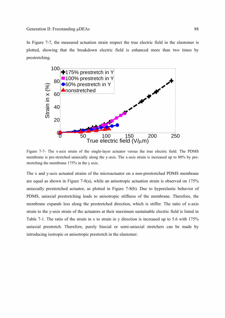
Generation II: Freestanding µDEAs 88
In Figure 7-7, the measured actuation strain respect the true electric field in the elastomer is
plotted, showing that the breakdown electric field is enhanced more than two times by
prestretching.
Figure 7-7- The x-axis strain of the single-layer actuator versus the true electric field. The PDMS
membrane is pre-stretched uniaxially along the y-axis. The x-axis strain is increased up to 80% by pre-
stretching the membrane 175% in the y axis.
The x and y-axis actuated strains of the microactuator on a non-prestretched PDMS membrane
are equal as shown in Figure 7-8(a), while an anisotropic actuation strain is observed on 175%
uniaxially prestretched actuator, as plotted in Figure 7-8(b). Due to hyperelastic behavior of
PDMS, uniaxial prestretching leads to anisotropic stiffness of the membrane. Therefore, the
membrane expands less along the prestretched direction, which is stiffer. The ratio of x-axis
strain to the y-axis strain of the actuators at their maximum sustainable electric field is listed in
Table 7-1. The ratio of the strain in x to strain in y direction is increased up to 5.6 with 175%
uniaxial prestretch. Therefore, purely biaxial or semi-uniaxial stretchers can be made by
introducing isotropic or anisotropic prestretch in the elastomer.
0 50 100 150 200 2500
20
40
60
80
100
True electric field (V/m)
Str
ain
in x
(%
)
175% prestretch in Y100% prestretch in Y60% prestretch in Ynonstretched

89 7.4. Characterization
Figure 7-8- Actuated strains in the x and y direction versus the true electric field for a single-layer
actuator. (a) Non-prestretched membrane. (b) The membrane is prestretched by 175% along the y
direction. The ratio of x to y axis strains is tunable by adjusting the prestretch level in x and y directions.
The effect of uniaxial prestretching on performance of the microactuators is summarized in
Table 7-1. The sustainable electric field and the strain level are enhanced by prestretching as the
pull-in instability occurs at higher strains [60] when in the hyperelastic regime.
Table 7-1- Effect of uniaxial prestretch level on performance of the microactuators.
Prestretch level
along y axis (%)
Maximum
strain in x (%)
y
x
Strain
Strain
Maximum Sustainable electric
field (V/µm)
0 7.7 1 106
60 14.5 1.2 124
100 29.2 2 140
175 80.7 5.6 241
7.4.2. Characterization of double-layer actuators
As described in section 7.2, in order to use the abovementioned actuators for cell stretching
applications, a 20 µm layer of PDMS is bonded on the actuators to avoid short-circuiting of the
top microelectrodes in the conductive cell growth medium which would lead to actuation over
the full length of the electrode and not only at the intersection of the top and bottom electrodes.
0 20 40 60 80 100 1100
2
4
6
7
True electric field (V/m)
Str
ain
(%
)
Non-stretched
Strainx
Strainy
0 50 100 150 200 2500
20
40
60
80
True electric field (V/m)
Str
ain
(%)
175% Prestretch in Y
Strainx
Strainy
(a) (b)
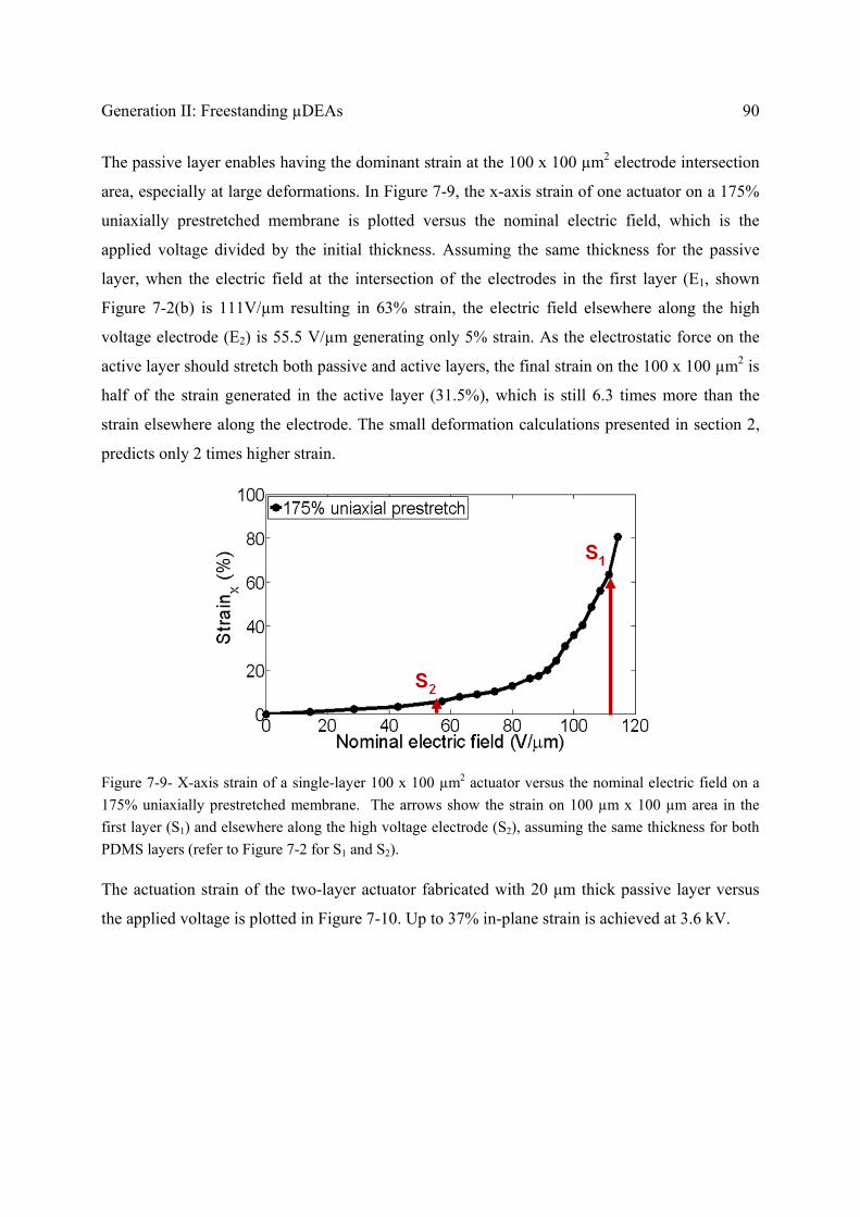
Generation II: Freestanding µDEAs 90
The passive layer enables having the dominant strain at the 100 x 100 µm2 electrode intersection
area, especially at large deformations. In Figure 7-9, the x-axis strain of one actuator on a 175%
uniaxially prestretched membrane is plotted versus the nominal electric field, which is the
applied voltage divided by the initial thickness. Assuming the same thickness for the passive
layer, when the electric field at the intersection of the electrodes in the first layer (E1, shown
Figure 7-2(b) is 111V/µm resulting in 63% strain, the electric field elsewhere along the high
voltage electrode (E2) is 55.5 V/µm generating only 5% strain. As the electrostatic force on the
active layer should stretch both passive and active layers, the final strain on the 100 x 100 µm2 is
half of the strain generated in the active layer (31.5%), which is still 6.3 times more than the
strain elsewhere along the electrode. The small deformation calculations presented in section 2,
predicts only 2 times higher strain.
Figure 7-9- X-axis strain of a single-layer 100 x 100 µm2 actuator versus the nominal electric field on a
175% uniaxially prestretched membrane. The arrows show the strain on 100 µm x 100 µm area in the
first layer (S1) and elsewhere along the high voltage electrode (S2), assuming the same thickness for both
PDMS layers (refer to Figure 7-2 for S1 and S2).
The actuation strain of the two-layer actuator fabricated with 20 μm thick passive layer versus
the applied voltage is plotted in Figure 7-10. Up to 37% in-plane strain is achieved at 3.6 kV.

91 7.4. Characterization
Figure 7-10- X-axis strain of a double-layer 100 x 100 µm2 actuator versus the applied voltage, showing
up to 37% relative strain. The first layer is uniaxially prestretched 160%, thickness of the stretched
membrane is 34 μm after prestretching and thickness of the coated passive layer is 20 µm.
7.4.3. Dynamic response
Dynamic response of a double layer 100 µm x 100 µm actuator is measured, using a Basler
A622f camera capable of grabbing 25 frames per second, and plotted in Figure 7-11. The
response time of the actuator is about 50 ms, allowing actuating at frequency of up to 40 Hz,
amply sufficient for stretching biological cells.
Figure 7-11- Dynamic response of a double layer actuator measured in air. Data points are the measured
actuation strain at each recorded frame. The response time of the actuator is about 50 ms.
0 1000 2000 3000 36000
10
20
30
40
Voltage (V)
X-a
xis
stra
in

Generation II: Freestanding µDEAs 92
7.5. Conclusion
Employing the non-linear mechanical properties of dielectric elastomers, I developed an array of
100 x 100 µm2 dielectric elastomer actuators generating up to 80% in-plane strain. The elastomer
was uniaxially prestretched 2.75 times its initial length to suppress the pull-in instability allowing
high actuation strain in the transverse direction which is softer. The experimental data are in well
agreement with the theoretical calculations delivered in Chapter 4.
The compliant 100 µm wide electrodes were patterned by gold ion-implantation and remained
conductive and functional up to 118% area strain, at which point the actuators fail. Low energy
ion-implantation is a very effective method to pattern compliant microelectrodes, addressing the
lack of suitable fabrication techniques to pattern µm scale electrodes on silicone membranes.
The array of microactuators was designed to stretch single cells attached on top of them in order
to study the mechanotransduction in single cell level. To avoid short-circuiting the top
microelectrode in the conductive cell culture medium, a passive biocompatible PDMS layer was
bonded on top. In this configuration, up to 37% in-plane strain was achieved at 3.8 kV with 50
ms response time, which adequately meets the desired strain levels and frequencies for
stimulating all cell types. The fabrication process of this device is further developed in the next
chapter to use it in the biological experiments.
Most of the material in this chapter is published in Journal of Sensors and Actuators A: Physical
2012, Vol. 186, Pages 236–241 and also Procedia Engineering 2012, Vol. 25, 693-696.

Chapter 8 DEA based cell stretcher*
8.1. Summary
Up to now, I have mostly focused on development of dielectric elastomer microactuators with
fast and large actuation deformation. In this chapter, to use the actuators for cell stretching
applications, I first address how to make a cell-friendly environment. The biocompatibility of the
elastomers used in the fabrication is investigated and the solution to eliminate the electric field
approaching the cells is discussed. Then, a reproducible fabrication process for making double
layer DEAs is presented and life time of the device in conductive liquid is studied. Finally, we
have cultured myoblast cells on the device and stretched them by applying 4.2 kV to the
actuators for 4 hours. The cells were healthy after operation and some of them have even divided
during this period. Also the device had well operated in the required living conditions for cells at
relatively high humidity and temperature, while covered with conductive cell growth medium.
8.2. biocompatibility of elastomers
To avoid short circuiting the top ground electrodes in the second generation of devices with
perpendicular electrodes by the conductive ground electrode, I have coated a passive PDMS
layer on the actuators (section 7.2). This layer also enhances the life time of the actuators
* The biological experiments are performed in close collaboration with Space Biology group at ETHz. Thanks to Dr. Alfredo Franco-Obregon and Mr. Krzysztof Krawczyk.

Chapter 8 DEA based cell stretcher 94
operating in the conductive medium. I have used Sylgard 186 or RTV 734 (Dow Corning®),
which is a flowable sealant curing by exposure to the moisture [141] for fabrication of the
passive layer. Since the cells will be cultured on this layer, the elastomeric PDMS layer should
be biocompatible. I have verified the biocompatibility of the elastomers by performing a live
dead assay. 5 mm thick PDMS layer from Sylgard 186 and RTV 734 were prepared and cut in to
5 cm x 5 cm pieces and placed in a sterile petri dish. To sterilize, 1-2 ml of ethanol 70% is
poured on the PDMS pieces and aspirated. The PDMS parts are then washed by adding 1-2 ml
phosphate buffered saline (PBS) and removing it, for three times. Next, the C2C12 Mouse
myoblast cells are added on the PDMS layers and 6 ml cell growth media containing 79%
DMEM high glucose (Invitrogen [142]), 20% Fetal bovine serum (FBS), and 1 % penicillin and
Streptomycin is poured in the petri dish. The cells are incubated for one day in an incubator at
37ºC and 5 % CO2. Then, the cells are detached from the PDMS layers by adding 1 ml of
Trypsin enzyme diluted in 3 ml PBS after 10 minutes of incubation. The cells are pelleted by
centrifuging to remove the trypsin and the old media and re-suspended in 1 ml of fresh media by
gently pipetting up and down. Next, 10 µl of the media with suspended cells is mixed with 10 µl
of Trypan blue dye and then, 10 µl of the solution is inserted in a hemacytometer. In theory, only
the dead cells, having a permeable membrane, take up Trypan blue and become blue. The
number of live and dead cells found in the hemacytometer are counted for each elastomer and
listed in Table 8-1. The cell viability is 94% for Sylgard 186, 97% for RTV 734 and 96% for a
control sample on a traditionally used sterile plastic petri dish for cell culture. These results
confirm that both Syglard 186 and RTV 734 are not harmful to the cells and can be used in the
biocompatible cell stretching device.
Table 8-1- Biocompatibility of the elastomers used in fabrication of cell stretching device
Material Live cells Dead cells Viability
RTV 734 206 6 97%
Sylgard 186 161 11 94%
Control (plastic petri dish) 225 10 96%

95 8.3. Electric field elimination
8.3. Electric field elimination
To make a cell stretcher device based on dielectric elastomer actuators operating at a couple of
kVs voltage, cells should be protected from the electric shock and electric field. As previously
described, the high voltage is always applied to the electrode on the bottom surface of the PDMS
membrane. In this case, the cells are protected from the high voltage; however, the electric field
can reach the top surface through the air which should be shielded assuring the cells are not
stimulated with an unknown electric field. For predicting this fringe-electric field, a simplified
model of the actuators as the worst case scenario is modeled in ANSYS and analyzed
electrostatically. A 60 µm thick and 2 cm wide silicone membrane with a high voltage applied to
the bottom surface and a ground electrode on top is modeled. To allow modeling the fringe
electric field through the air, the silicone membrane with relative permittivity of 3 is placed in air
(εr=1), as shown in Figure 8-1.
Figure 8-1- schematic of the simplified model of the actuators for electrostatic analysis; A 60 µm thick
and 2 cm wide silicone membrane is placed in air. The high voltage is applied to the bottom electrode and
the top electrode is at 0V.
The calculated electric field by FEM simulation at 15 µm distance above the top layer of the
silicone membrane is plotted in Figure 8-2, when 2 or 3 kV electric voltage is applied to the
bottom electrode. The electric field is higher at the edges of the membrane due to the fringe field
effect. At the center of the membrane, the electric field is 65 V/mm when 2 kV is applied to the
electrode. Biologists accept 1 V/mm as a sustainable electric field for cells and the cells respond
to the electrical stimulation of above 10 V/mm [123]. Based on our calculation, the approached

Chapter 8 DEA based cell stretcher 96
electric field to the cells is higher than the acceptable threshold, making it possible that the cells
sense and respond to the electrical stimulation as well as the mechanical stimulation.
Figure 8-2- The computed electric field on 15 µm above the top ground electrode using ANSYS. The
electric field approaches the surface through the air. The electric field is about 100 V/mm which is above
the acceptable threshold.
The performed simulation is the worst case scenario as the conductive liquid covering the cells is
not simulated. To be fully assured that the electric field reaching to the top surface is confined
and the mechanical field is the dominant field sensed by the cells, I connect the cell growth
media it to the ground while the device is operating. This eliminates all the possible approaching
electric field to the cells.
8.4. Device fabrication
In Chapter 7, the fabrication steps for dielectric elastomer actuators generating large deformation
was briefly mentioned. In this section, I will discuss reliable fabrication steps making a cell
stretching device compatible with the biological equipment. The device that I have developed is
a chip scale device that can fit in the conventional incubators and doesn’t need a mounted heat
chamber. Moreover, it can fit on the inverted microscopes and since the dielectric elastomers

97 8.4. Device fabrication
used are transparent and the ion-implantation leads to semi-transparent electrodes, it can be used
for live microscopy without any further modification.
First, 50 µm thick Sylgard 186 membrane is fabricated on a polyimide sheet with the same
technique as described in section 6.5.2. The membrane is prestretched 2.7 times its initial length
using a small uniaxial prestretcher made by CNC, as shown in Figure 8-3. The membrane on the
polyimide film is cut and fixed with double sided film on the two plastic rods in Figure 8-3 (a).
The polyimide film is then removed by mechanical force leaving a suspended membrane on the
rods. Next, one of the rods is fixed in the groove of the stretcher and the other one is stretched
and fixed in the next groove, as shown in Figure 8-3 (b). The orange kapton tape fixes the four
edges of the elastomer on the frame after prestretch (Figure 8-3 (c)). The ratio between the
distance between the grooves on the stretcher and the initial length of the membrane defines the
uniaxial prestretch ratio in the elastomer.
Figure 8-3- (a) A small uniaxial prestretcher is used to uniaxially prestretch the elastomer. (b) The
elastomer is fixed on the two rods with double sided tape and one rod is fixed in the upper groove and the
membrane is uniaxially stretched till the second rod fits in the second groove. (c) Shows the prestretched
membrane fixed on the frame.
In the next step, ion-implanted electrodes are patterned on the elastomer. A 50 µm thick laser cut
stencil mask is used to pattern 25 mm long 100 µm wide electrodes by ion-implantation. As
mentioned in section 5.3, to pattern uniform electrodes, the scanning length should be 40 mm.
The acceleration voltage of the implanter is set to -1.25 kV and the ion-dose is close to the
percolation threshold to minimize the stiffening impact of the electrodes. The shadow mask fits
in the opening of the prestretcher and is directly placed on the prestretched elastomer. The
PDMS elastomer sticks well to the mask eliminating the gap between the mask and the
elastomer.

Chapter 8 DEA based cell stretcher 98
After patterning two perpendicular arrays of electrodes on both sides of the elastomer, two
printed circuit boards (PCBs) are bonded to the prestretched frame to fix the prestretch and to
enable the electrical contact with the ion-implanted electrodes. To effectively fix the PCBs on
the prestretched elastomer, RTV 734 elastomer is dispensed around the inner and outer boundary
of the PCB and cured at room temperature for half an hour, as shown in Figure 8-4 (a). It is
necessary to wait till the top PCB is well fixed and the RTV glue is cured and then fix the bottom
PCB, otherwise, the membrane ruptures. Next, the membrane is separated from the prestretching
frame and is clamped between the two PCBs (Figure 8-4 (b)). To ease the electrical connections
to the backside of the membrane and minimize the total thickness of the device to be in the
working distance of the inverted microscopes, another PCB is added to the bottom PCB, as
shown in Figure 8-4 (c).
Figure 8-4- (a) after patterning perpendicular arrays of electrode on both sides of the elastomer, a PCB is
attached on each layer to the membrane to fix the prestretch and enable electrical connection to the
electrodes. (b) The prestretched elastomer is clamped between two PCBs. (c) To ease the electrical
connection to the bottom electrodes, another PCB is added to the device.
As the last fabrication step, it is required to bond the passive elastomeric membrane on the
actuators. Spray coating or spinning the polymer on the actuators does not give uniform layers
therefore; an elastomeric membrane from either RTV 734 or Sylgard 186 is made on the
polyimide films with the desired thickness (25 µm-30 µm). Then, the membrane is bonded on a
glass or PDMS dish and bonded to the prestretched actuators. When the elastomer is removed
from the substrate it doesn’t form a flat surface, as shown in Figure 8-5 (a). Therefore, the
elastomer is first bonded to the plastic ring using a double sided tape and removed from the
polyimide substrate and then again placed on the substrate to show that the membrane is not
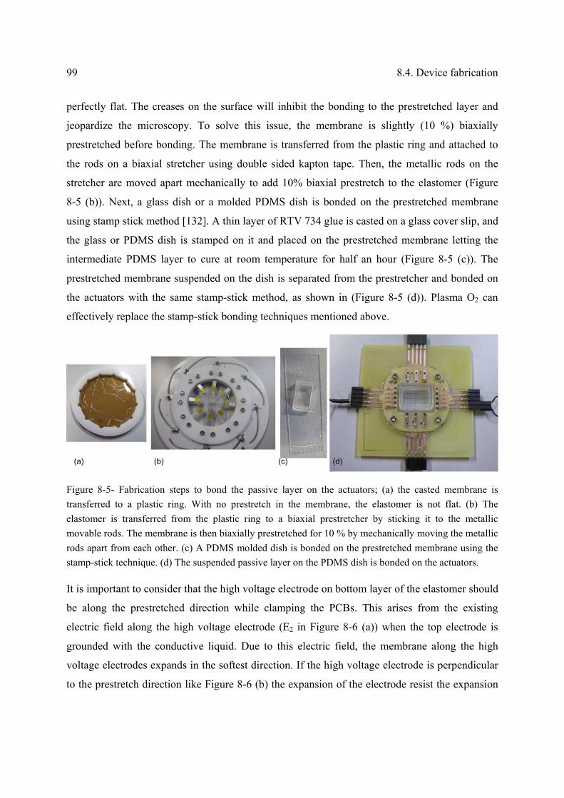
99 8.4. Device fabrication
perfectly flat. The creases on the surface will inhibit the bonding to the prestretched layer and
jeopardize the microscopy. To solve this issue, the membrane is slightly (10 %) biaxially
prestretched before bonding. The membrane is transferred from the plastic ring and attached to
the rods on a biaxial stretcher using double sided kapton tape. Then, the metallic rods on the
stretcher are moved apart mechanically to add 10% biaxial prestretch to the elastomer (Figure
8-5 (b)). Next, a glass dish or a molded PDMS dish is bonded on the prestretched membrane
using stamp stick method [132]. A thin layer of RTV 734 glue is casted on a glass cover slip, and
the glass or PDMS dish is stamped on it and placed on the prestretched membrane letting the
intermediate PDMS layer to cure at room temperature for half an hour (Figure 8-5 (c)). The
prestretched membrane suspended on the dish is separated from the prestretcher and bonded on
the actuators with the same stamp-stick method, as shown in (Figure 8-5 (d)). Plasma O2 can
effectively replace the stamp-stick bonding techniques mentioned above.
Figure 8-5- Fabrication steps to bond the passive layer on the actuators; (a) the casted membrane is
transferred to a plastic ring. With no prestretch in the membrane, the elastomer is not flat. (b) The
elastomer is transferred from the plastic ring to a biaxial prestretcher by sticking it to the metallic
movable rods. The membrane is then biaxially prestretched for 10 % by mechanically moving the metallic
rods apart from each other. (c) A PDMS molded dish is bonded on the prestretched membrane using the
stamp-stick technique. (d) The suspended passive layer on the PDMS dish is bonded on the actuators.
It is important to consider that the high voltage electrode on bottom layer of the elastomer should
be along the prestretched direction while clamping the PCBs. This arises from the existing
electric field along the high voltage electrode (E2 in Figure 8-6 (a)) when the top electrode is
grounded with the conductive liquid. Due to this electric field, the membrane along the high
voltage electrodes expands in the softest direction. If the high voltage electrode is perpendicular
to the prestretch direction like Figure 8-6 (b) the expansion of the electrode resist the expansion

Chapter 8 DEA based cell stretcher 100
of the membrane on the actuators and decrease the actuators’ strain. To avoid this phenomenon,
the high voltage electrodes should be along the prestretch direction to not influence the actuation
strain on the actuator, as shown in Figure 8-6 (c).
Figure 8-6- (a) Schematic cross section of the double layer actuator. When the top electrode (conductive
liquid) is grounded, the electric field along the high voltage electrode is E2. (b) If the high voltage
electrode is patterned perpendicular the prestretch direction, expansion of the membrane on the HV
electrode resists the expansion on the membrane. (c) The HV electrode should be patterned along the
prestretch direction to not decrease the actuation strain on the actuator.
In Figure 8-7 (a), the fabricated array of 25 100 µm x 100 µm dielectric elastomer actuators is
shown. Each group of 5 actuators can be operated at a different voltage or frequency allowing
high throughput studies. The double layer actuators are shown in Figure 8-7 (b), where the cells
are cultured in the glass dish. The conductive cell growth medium is connected to zero voltage to
eliminate the chance of reaching the electric field to the cells. A small lid is placed on the glass
dish to avoid contamination while the cells are cultured and incubated.

101 8.5. Operating in conductive liquid
Figure 8-7- (a) The fabricated prototype of arrays of 25 100 µm x 100 µm dielectric elastomer actuators.
(b) Double layer cell stretching device; the cells are cultured in the glass dish and the cell growth medium
is grounded to eliminate the chance of approaching the electric field to the cells through the air. Each
group of 5 actuators can be actuated independently at a different voltage or frequency.
8.5. Operating in conductive liquid
Cells regulate their biochemical responses over a time scale of a few minutes to a few hours for
periodic strains [2, 3]. During this time period, the cells should be incubated in sterile living
conditions; covered with cell growth medium at 37ºC temperature and 5% CO2, which is
required to adjust the pH of the cell growth medium. In our cell stretching device that the cells
are stretched with the flexible actuators to which they are attached, it is required that the
actuators can operate in liquid environment for at least a few hours. Dielectric elastomer
actuators normally have a short life time when they are exposed to conductive liquid. Typically,
the ions diffuse in the elastomer leading to break down at lower working cycles compared to the
DEAs operating in dry environment. Kornbluh et al. investigated the life time of VHB based
DEAs operating at different humidity ratios and strain rates [85, 143]. They have observed two
orders of magnitude higher working cycles for the devices operating in dry conditions compared
to the ones operating in open air. At 100 % relative humidity, the devices have failed after 3000
of cycles at 42 V/µm and after 5 cycles at 64 V/µm. In our lab, the break down strength of
Sylgard 186 was measured after immersing the elastomer in salt water for few hours. The
elastomer was taken out from the liquid, dried and then the breakdown voltage was measured.
We observed no degradation in breakdown strength of the elastomer. However, when the
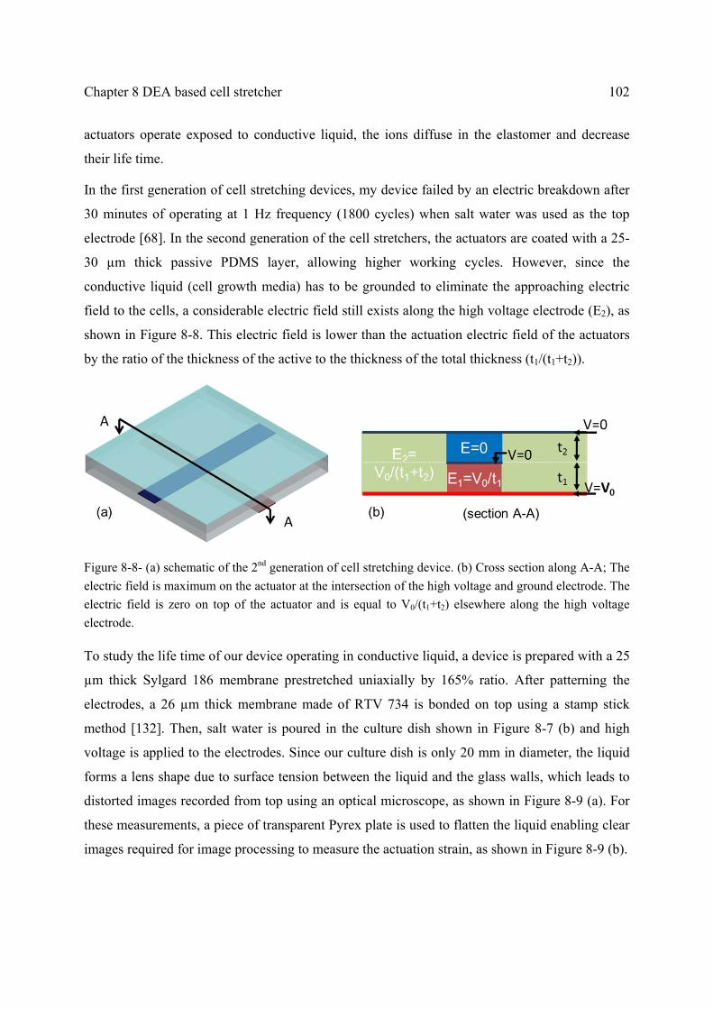
Chapter 8 DEA based cell stretcher 102
actuators operate exposed to conductive liquid, the ions diffuse in the elastomer and decrease
their life time.
In the first generation of cell stretching devices, my device failed by an electric breakdown after
30 minutes of operating at 1 Hz frequency (1800 cycles) when salt water was used as the top
electrode [68]. In the second generation of the cell stretchers, the actuators are coated with a 25-
30 µm thick passive PDMS layer, allowing higher working cycles. However, since the
conductive liquid (cell growth media) has to be grounded to eliminate the approaching electric
field to the cells, a considerable electric field still exists along the high voltage electrode (E2), as
shown in Figure 8-8. This electric field is lower than the actuation electric field of the actuators
by the ratio of the thickness of the active to the thickness of the total thickness (t1/(t1+t2)).
Figure 8-8- (a) schematic of the 2nd generation of cell stretching device. (b) Cross section along A-A; The
electric field is maximum on the actuator at the intersection of the high voltage and ground electrode. The
electric field is zero on top of the actuator and is equal to V0/(t1+t2) elsewhere along the high voltage
electrode.
To study the life time of our device operating in conductive liquid, a device is prepared with a 25
µm thick Sylgard 186 membrane prestretched uniaxially by 165% ratio. After patterning the
electrodes, a 26 µm thick membrane made of RTV 734 is bonded on top using a stamp stick
method [132]. Then, salt water is poured in the culture dish shown in Figure 8-7 (b) and high
voltage is applied to the electrodes. Since our culture dish is only 20 mm in diameter, the liquid
forms a lens shape due to surface tension between the liquid and the glass walls, which leads to
distorted images recorded from top using an optical microscope, as shown in Figure 8-9 (a). For
these measurements, a piece of transparent Pyrex plate is used to flatten the liquid enabling clear
images required for image processing to measure the actuation strain, as shown in Figure 8-9 (b).

103 8.5. Operating in conductive liquid
Figure 8-9- (a) Distorted images due to the lens effect of the liquid in the cell growth dish on the actuators
when looking from top using an optical microscope. (b) A transparent Pyrex plate is used to flatten the
liquid enabling clear images to be recorded.
The actuation strain of one of the actuators at 3.8 kV and 1 Hz is measured and plotted in Figure
8-10. The actuation strain is increased initially and then decreased to the initial strain after 1
hour. Afterward, the strain remained constant till hour 5.5 and finally degraded to half of the
initial actuation strain after 8 hours of actuation.
Figure 8-10- Actuation strain of an actuator operated at 3.8 kV and 1 Hz while covered with grounded conductive liquid on top measured over time. The actuation strain degrades to half of the initial strain after 8 hours of operation (29040 cycles).
To fully understand the mechanism behind this strange behavior, more experiments should be
performed. I speculate that diffusing the ions in the elastomer modifies the stiffness and/or the
Chapter 8 DEA based cell stretcher 104
permittivity of the elastomer leading to the observed variation of the actuation strain over time.
To enhance the life time of the device operating in conductive liquid, the most effective method
is to find or develop an impermeable elastomer for the passive layer. It is also recommended to
deposit a 100 nm thick Parylene layer on the PDMS membrane and later etch this layer away
with plasma O2. It has been reported that this procedure caulks the PDMS pores and thus seals
the membrane without stiffening it [136].
8.6. Biological experiment
In our initial assay to stretch living cells using our device, we randomly cultured myoblast cells
on the membrane. We let the cells rest on the membrane for a day to well expand and adhere on
the membrane and then stretched them for four hours with a periodic strain at 1 Hz. First, I
describe the protocol for the biological experiment and then discuss the results.
First, the top membrane and the culture dish are sterilized by filling the dish with 70% ethanol
and empting it after 10 seconds. Then, the membrane is washed with PBS (phosphate buffered
saline) for three times. The ethanol should not remain on the membrane for a long time as the
PDMS membrane takes up the alcohol and swells. The resulting internal stress then breaks the
prestretched membrane.
A thin layer of extracellular matrix, Collagen I (Gibco®, Invitrogen Corp, USA), is coated on the
elastomer to enhance the adherence of the cells to the PDMS membrane. To improve uniformity
of this layer, the PDMS membrane is exposed to UV for one minute in the cell culture hood to
render the surface hydrophilic. Then, 5 µg/cm2 is coated on the membrane following the protocol
recommended by the manufacturer [144].
C2C12 mouse myoblast cells are detached from their initial flask and transferred to the device
and covered with 1 ml of cell growth media containing 79% DMEM high glucose (Gibco®,
Invitrogen Corp, USA [142]), 20% fetal bovine serum and 1% penicillin and streptomycin. The
culture dish is covered with a lid allowing oxygen in and prohibiting the contamination from the
cells. The cells are incubated at 37ºC and 5% CO2 for a day to let them expand and adhere well
to the membrane.

105 8.6. Biological experiment
High voltage is applied to the bottom electrode and the top electrode and the cell growth medium
are grounded. Since the elastomers used in fabrication of the device are transparent and ion-
implantation leads to semi-transparent electrodes, it is possible to image the cells live while they
are actuated. The rigid PCBs required to connect to the electrodes and to fix the prestretch of the
elastomer are carefully designed to be in the working distance of conventionally used inverted
microscopes. Figure 8-11 shows the cells that are randomly cultured on the device. One of the
cells is placed on one of the electrodes. The cell is well attached to the membrane and is
stretched when the membrane expands by applying 4.2 kV to the electrode.
Figure 8-11- Cells are randomly cultured on the device. One cell is adhered on the high voltage electrode
and stretched with the membrane when 4.2 kV is applied to the electrode.
The device is then put back in the incubator and operated at 4.2 kV for four hours. Each actuator
is named to be able to monitor the cells performance before and after actuation. Figure 8-12
shows the images taken before and after actuation for four hours at one Hz on two of the
actuators (C3 and B2). The images are recorded in the differential interface contrast (DIC) and
the phase contrast modes and are shown in two consequent rows.
The cells are healthy after 4 hours of operation at 4.2 kV and some of them have even divided
during this period. Also the device had well operated in the required living conditions for cells at
relatively high humidity and temperature, while covered with conductive cell growth medium.
To quantitatively study the biochemical response of the cells in response to the applied
mechanical strain with the device, more detailed experiments should be carried out with defined
protocols.

Chapter 8 DEA based cell stretcher 106
Before actuation After 4 hours at 4.2 kV 1 Hz
Act
uat
or (
C3)
Dif
fere
ntia
l int
erfe
renc
e
cont
rast
mic
rosc
opy
Act
uat
or (
C3)
Pha
se c
ontr
ast m
icro
scop
y
Act
uat
or (
B2)
Dif
fere
ntia
l int
erfe
renc
e
cont
rast
mic
rosc
opy
Act
uat
or (
B2)
Pha
se c
ontr
ast m
icro
scop
y
Figure 8-12- Images recorded on actuators C3 and B2 in the DIC and phase contrast mode are shown
before and after 4 hours of actuation at 4.2 kV at 1Hz.

107 8.7. Conclusion
8.7. Conclusion
The 2nd generation array of DE microactuators was further developed to fulfill the requirements
for a cell stretching device. Biocompatibility of the elastomers used in the fabrication was tested
and proven, and a solution to eliminate the possible approaching electric field to the cells was
discussed. A reproducible fabrication process with a high yield for developing DEA based cell
stretchers on highly prestretched elastomers was developed. The life time of the device operating
in conductive liquid at 3.8 kV and 1 Hz for 8 hours was investigated. The actuation strain
remained around the same level between time 1 hr and 5 hr, which is a great progress compared
to the first generation of cell stretching device. Finally, cells were grown and stretched on the
device at 4.2 kV. The cells were healthy after 4 hours of operation and the device had well
operated in the required living conditions for cells at relatively high humidity and temperature.
To quantitatively study the biochemical response of the cells to the applied mechanical stretch,
more detailed experiments should be carried out with defined protocols.

Chapter 9 Conclusions
9.1. Summary
In this chapter, I summarize the main achievements of this thesis and present an outlook for the
future research in this field.
9.2. Main achievements
I have successfully developed a high throughput cell stretching device based on dielectric
elastomer actuators that addresses the limitations of the available cell stretching devices. Arrays
of microactuators are integrated in the cell growth culture plate and can selectively stimulate
different cells with various strain levels. The actuation strain is adjustable with the applied
voltage simplifying the integration of many actuators in the same device without complexity of
other techniques such as the pneumatic actuation. The actuators are miniaturized to 100 µm x
100 µm to stretch isolated or small colonies of cells. Moreover, the actuation strain generated by
in-plane DE microactuators is uniform allowing stretching single cells with a predefined and
uniform strain.
I have developed two generations of µDEA arrays. The first generation consists of 100 µm x 200
µm actuators on a non-stretched PDMS membrane with patterned ion-implanted microelectrodes
bonded on a Pyrex chip with etched trenches. The conceptual design, finite element simulation,
fabrication and characterization of the actuators have been presented. Up to 5% uniaxial strain
109 9.2. Main achievements
can be generated with this device allowing to stretch the cells from stiff tissues with relevant
biological strains and frequencies. The actuation strain is enhanced up to 80% in the second
generation of cell stretchers by taking advantage of hyperelastic behavior of the dielectric
elastomers. The elastomeric membrane is uniaxially prestretched 2.75 times its initial length
stiffening the membrane in the prestretched direction and allowing large deformation in the
transverse direction. A 25-30 µm thick passive layer is bonded on the actuators to increase the
life time of the actuators while operating in conductive cell growth medium and to avoid short
circuiting of the actuators. Up to 37% strain can be generated with this generation which amply
meets the required relevant biological strain for all cell types. I further developed the second
generation actuators to develop a chip scale (4 cm x 4 cm) cell stretching device that easily fits in
the conventional incubators and can be used for live microscopy using the traditional inverted
microscopes. Finally, myoblast cells were cultured on the device and stretched at 4.2 kVs for 4
hours. The cells were clearly stretched with the substrate when the voltage was applied. They
were healthy after 4 hours of actuation, proving that the device is well compatible with biological
experiments. Moreover, the device had well operated in the required living conditions for cells
meaning at 37ºC and high humidity covered with conductive cell growth medium.
Table 5-1Table 9-1 compares the developed cell stretcher in this thesis with the commercially
available and the laboratory developed cell stretching devices. The commercially available cell
stretchers have Cm2 stretching area much too large to monitor single cell response. They also
suffer from low throughput as only a specific mechanical stress can be applied to all groups of
cells. Several researchers have introduced new approaches to address the limitations of the cell
stretchers by either increasing the throughput or miniaturizing the actuators to stretch isolated
cells. Up to now, there is only our device that can stretch arrays of isolated cells with a high
throughput with uniform mechanical strain at relevant biological frequencies and strains.
Moreover, our device is chip scale and portable that can fit in the conventional incubators. The
membrane is also transparent and the ion-implanted electrodes are semitransparent making it
possible to observe the cells through the membrane using conventional inverted microscopes.
Furthermore, thanks to the in-plane actuation strain, the cells remain in the focal plane during
stretching facilitating the live microscopy of the cells.

Chapter 9 Conclusions 110
Table 9-1- Performance comparison of the existing cell stretching devices
Authors Throughput Size Stretch
isolated cells
Strain
uniformity Max strain
Max
frequency
Flexcell INC
[25]
Low Cm2 No 33%
Strex [26] Low Cm2 No Yes 20% 1
Kamotani et
al. [33]
High Φ1.7 mm No No 30%
(elongation)
5
Simmons et
al.[38]
High 1.0 mm No Yes 10% 1
Moares et
al.[37]
High 500 µm No Yes 26%
Zhao et al.
[35]
Low 200 µm No No 8.5% 0.1
Sarrel et al.
[27]
Low Single cell Yes Yes >20% ~250 Hz
This work High 100x100
µm2
Yes Yes 37% 20 Hz
In this thesis, I have also provided theoretical guidelines for enhancing the actuation performance
of silicone based dielectric elastomer actuators, which paved the path towards developing the
µDEA array meeting the requirements for cell stretching application. The theoretical analysis is
targeted to castable dielectric elastomers such as silicones that are polymerized after casting to
make membranes of any desired thickness. When the thickness of the elastomer is decoupled
from the prestretch ratio, it is more effective to select a thinner membrane rather than highly
prestretching which unnecessarily stiffens the elastomer and deteriorates its performance. By
theoretical and experimental means, I have shown that uniaxial prestretching is an effective
technique towards large actuation.

111 9.3. Future outlooks
It should be mentioned that a provisional patent is filed on the high throughput cell stretching
device based on DEAs and the material presented in this thesis has been published in 3 Journal
articles and 4 Conference proceedings as listed in list of publications.
9.3. Future outlooks
Now that the preliminary biological experiments confirm that the device is compatible with
biological experiment, it is time to perform more quantified biological experiments and study the
cells’ response to the applied mechanical stimulation. Further engineering development is
required till a biologist can use it independently. The life time of the actuators operating exposed
to conductive liquid needs to be improved by finding/developing an impermeable passive layer.
It is ideal to have reproducible and repeatable week-long actuation.
For the first generation of cell stretcher, I have shown consistent actuation strain on the actuators
of one device (see Figure 6-17). For the second generation, operating in the large deformation
regime after the peak of voltage-strain curve (refer to section 4.6 or Figure 4-10 for example) a
slight change in voltage or material properties leads to significant difference in actuation strain.
Therefore, it is required to carefully control and homogenize the material properties, the
prestretch state, and the stiffening impact of the electrodes on all the actuators to achieve
consistent actuation strain on the device. Although low-energy metal ion-implantation allows
patterning microelectrodes (≤ 100 µm wide) with stiffening impact of less than 2, the stiffening
impact of the ion-implanted electrodes is nonlinearly dependent to the ion-dose; around the
percolation threshold, a slight difference in the dose leads to a large difference on the stiffness
(Figure 5-8). Furthermore, the ion-dose degrades during one implantation cycles due to several
known and unknown reasons such as the source wear. To control the ion-dose and the stiffness
of the ion-implanted electrode, additional hardware should be added to the implantation chamber
to monitor the sputtered dose of the beam, in real time, and to compensate for the dose
degradation if necessary.
As an alternative and more reliable approach than modifying the implanter, I recommend
patterning carbon-based electrodes, which have negligible stiffening impact on the elastomer.
Using a commercially available pad printer I have patterned compliant electrodes as small as 150
µm in width. For a cell stretching device, carbon-black should be replaced with carbon

Chapter 9 Conclusions 112
nanotubes or a mixture of them to develop semi-transparent electrodes required for microscopy
of the cells using inverted microscopes.
Following the theoretical guidelines given in Chapter 4, devices with uniaxial and biaxial
actuation strain can be developed by prestretching the elastomer in different modes to investigate
the cell response to various types of mechanical stimulation. Moreover, by patterning compliant
electrodes with different geometries, single cell sized actuators together with mm-size actuators
can be integrated on the same device to distinguish the effect of mechanical stimulation on a
single cell or on a group of cells in one experiment.
Due to the ms response of the actuators, the actuators can also be used to apply a mechanical
impulse to the cells to simulate e.g. brain injury in accidents or explosions.
Incorporating a self-sensing mechanism in the device is another interesting feature that enables
precise and real-time measurement of the sensed strain by the cells. Deformation of the actuators,
leads to change in the electrodes’ resistance and also the capacitance between the two compliant
electrodes, which could be used as a feedback for indirect measurement of the strain. To make a
resistance sensor, degradation of the compliant electrodes should be investigated and calibrated,
while the capacitive sensor requires precise noise-free Pico-farads measurement. It would be
particularly exciting to measure the force exerted by the cells in response to e.g. drugs as a high
throughput diagnostic tool or to measure the evolution of the cell stiffness over the actuation
period to study the cell differentiation.
List of publications
Journal Articles:
S. Akbari, S. Rosset, H. Shea, “Improved actuation deformation in castable dielectric 1.
elastomer actuators”, Applied Physics Letter, 2013, accepted, DOI: 10.1063/1.4793420.
S. Akbari, H. Shea, “Microfabrication and characterization of an array of dielectric 2.
elastomer actuators generating uniaxial strain to stretch individual cells”, 2012, Journal of
Micromechanics and Microengineering 22 045020. Selected by IOP, JMM highlights, and
research highlights of EPFL.
S. Akbari, H. Shea, “An array of 100 µm x 100 µm Dielectric Elastomer Actuators with 3.
80% Strain for Tissue Engineering Applications”, Sensors and Actuators A: 2012,186, 236–
241
Conference Proceedings:
S. Akbari, et al., “More than 10-fold increase in the actuation strain of dielectric elastomer 4.
actuators”, Proceeding of SPIE, San Diego, 2013.
S. Akbari, et al., “Stretching cells with DEAs”, Proceeding of SPIE, San Diego 2012. 5.
S. Akbari, H. Shea, “Arrays of 100 μm x 100 μm dielectric elastomer actuators to strain the 6.
single cells”, Procedia Chemistry, 2011.
S. Akbari, et al., “Arrays of EAP micro-actuators for single-cell stretching applications”, 7.
Proceeding of SPIE, San Diego, 2010.

List of publications 114
A. Punning, S. Akbari, M. Niklaus, H. Shea, “Multilayer dielectric elastomer actuators with 8.
ion implanted electrodes”, Proceeding of SPIE, San Diego 2011 pp. 79760U.
Poster Presentations:
S. Akbari, et al., “Stretching cells with artificial muscles”, NanobiotechMontreux, 9.
Montreux, Nov 2012.
S. Akbari, et al., “Electroactive Micro-Actuators To Stimulate Single Cells With Uniaxial 10.
Mechanical Strain”, EuroEAP Conference, Pisa, June 2011.
S. Akbari, H. Shea, “An Array of Electroactive Polymer Micro Actuators to Apply Uni-11.
Axial Stress To Single Cells”, MMB conference, Lucern, May 2011.
S. Akbari, et al, “Arrays of 100 X 200 µm2 Polymer Actuators to Apply Strain to Single 12.
Cells”, Nanobio conference, Zurich, August 2010.
Provisional patent:
US Provisional Patent Application No. 61/697,393 filed on September 6, 2012
"HIGH THROUGHPUT CELL STRETCHING DEVICE"
Inventors: Samin AKBARI, Herbert SHEA, Luc MAFFLI

115 Appendix
Appendix: Internship at Harvard University
I had the opportunity to join Weitzlab at the school of applied engineering of Harvard University
from April to October 2012. Here, I will briefly discuss the research I carried out during my visit.
I developed a droplet based microfluidics for high throughput encapsulation of single cells in
alginate microparticles with high cell viability. Then, I used this system for high throughput
screening of antigen-specific antibody secreting cells.
Cell-encapsulation in Alginate microparticles
Cell encapsulation in hydrogel microbeads has promising applications in tissue engineering,
regenerative medicine and cell-based drug delivery [145-150]. Encapsulated cells can secrete
therapeutic proteins in response to an external stimulus over an extended time period to treat
various diseases including renal failure and diabetes [151, 152]. In cell transplantation therapy
for ischemic heart diseases, while direct injection of cells results in limited cell survival,
encapsulation in hydrogels improves cell growth and transplantation efficiency [153, 154]. Of all
hydrogels, alginate is one of the most suitable biomaterials for cell encapsulation due to its
biocompatibility, biodegradability, similarities to the natural extracellular matrix, and ease of
gelation[155]. Alginate is a naturally derived polymer which can physically cross-link with
divalent ions to provide an ideal three-dimensional scaffold for cells that allows bidirectional
diffusion of nutrients and waste products.
Alginate beads are typically produced by ejecting drops of alginate solution into a bath of
divalent ions resulting in millimeter-sized polydisperse beads [156-158]. As carriers of drugs,
proteins or cells, it is crucial to precisely control particle size, monodispersity and generation
frequency to perform high throughput studies in a quantitative fashion and at low cost. To
address this need, droplet-based microfluidics offers a powerful method to produce
monodisperse alginate microdroplets [159-164].
I developed an improved droplet-based microfluidic device for encapsulation of mammalian
cells in monodisperse alginate microparticles of 26-41 µm diameters with high viability. I
encapsulated antibody-secreting hybridoma cells (9E10 cell line) and mouse breast cancer cells

Appendix: Internship at Harvard University 116
(M6C cell line) within alginate microparticles. Droplets containing the cells and CaCO3
nanoparticles as gelation agents are shown in oil prior to gelation (Fig. 1 (a)), and microparticles
containing cells after gelation and transfer to cell growth medium are shown in Fig. 1 (b). To
evaluate cell viability, the cells are stained with calcein AM (live stain, green) and ethidium
homodimer (dead stain, red). Over 84% of the cells from both cell types were viable when
assayed immediately after the encapsulation and washing process.
Fig. 1. (a): Bright field image of 35 µm alginate droplets in oil, prior to gelation. Droplets contain cells and CaCO3 nanoparticles. (b): Confocal microscopic image of the encapsulated cells inside the alginate microparticles after gelation and transfer to cell growth medium. Green fluorescence represents live cells stained by calcein AM. (c): Percentage cell viability determined from the fraction of live cells. The scale bars are 25µm. An article is written on the encapsulation technique and will be submitted soon.

117 Appendix
High throughput screening of target-specific secreting cells
After successful encapsulation of mammalian cells in alginate microparticles, I used this
technique to screen the antigen-specific secreting cells.
Screening single cells secreting target-specific antibody is the first step to produce monoclonal
antibodies that are becoming the fastest growing class of human therapeutic. Antibodies can bind
to specific target proteins or cells and stimulate the immune system to attack those cells or
pathogens.
We introduced a novel technique to functionalize the hydrogel microparticles (patent pending) to
entrap the antigen-specific secreted antibodies. I encapsulated two different antibody secreting
mouse hybridoma cell lines (TNF-α and 9E10) in 40 µm diameter alginate particles. 9E10 cell
lines are labeled with CMRA orange dye before encapsulation as shown in Fig. 2 (a) and (b).
Protein molecules binding specifically to the secreted TNF-α antibody are labeled with a green
fluorescent molecule and encapsulated in all the particles initially. After washing the particles
after incubating the cells for 2 hours, to allow enough antibody secretion, only the particles
containing TNF-α cells are labeled as green meaning that they secret the antibody against the
target molecule as shown in Fig. 2 (c).
Fig. 2- Screening of target-specific antibody secreting cells. (a) Two different mouse hybridoma cell lines secreting different monoclonal antibodies are encapsulated in hydrogel microparticels. (b) The 9E10 cells are labeled as red before encapsulation. (c) Only the particles containing the TNF-α cells secreting against the green antigen have retained the green color.

References 118
References
[1] Putnam, A.J., et al., "Microtubule assembly is regulated by externally applied strain in cultured smooth muscle cells," Journal of cell science, 111(22), p. 3379-3387 (1998).
[2] Song, G., et al., "Regulation of cyclic longitudinal mechanical stretch on proliferation of human bone marrow mesenchymal stem cells," Molecular and Cellular Biomechanics, 4(4), p. 201 (2007).
[3] Wang, J.H.C. and B. Thampatty, "An introductory review of cell mechanobiology," Biomechanics and modeling in mechanobiology, 5(1), p. 1-16 (2006).
[4] Sarasa Renedo, A. and M. Chiquet, "Mechanical signals regulating extracellular matrix gene expression in fibroblasts," Scandinavian journal of medicine & science in sports, 15(4), p. 223-230 (2005).
[5] Bao, G. and S. Suresh, "Cell and molecular mechanics of biological materials," Nature materials, 2(11), p. 715-725 (2003).
[6] Kim, D.H., et al., "Microengineered platforms for cell mechanobiology," Annual review of biomedical engineering, 11, p. 203-233 (2009).
[7] Hochmuth, R.M., "Micropipette aspiration of living cells," Journal of Biomechanics, 33(1), p. 15-22 (2000).
[8] Sato, M., M.J. Levesque, and R.M. Nerem, "Micropipette aspiration of cultured bovine aortic endothelial cells exposed to shear stress," Arteriosclerosis, Thrombosis, and Vascular Biology, 7(3), p. 276-286 (1987).
[9] Dao, M., C.T. Lim, and S. Suresh, "Mechanics of the human red blood cell deformed by optical tweezers," Journal of the Mechanics and Physics of Solids, 51(11–12), p. 2259-2280 (2003).
[10] Berns, M.W. and K.O. Greulich, Laser manipulation of cells and tissues. 2007: Elsevier Academic Press.
[11] Trepat, X., et al., "Universal physical responses to stretch in the living cell," Nature, 447(7144), p. 592-595 (2007).
[12] Lulevich, V., et al., "Cell mechanics using atomic force microscopy-based single-cell compression," Langmuir, 22(19), p. 8151-8155 (2006).
[13] Mathur, A.B., et al., "Endothelial, cardiac muscle and skeletal muscle exhibit different viscous and elastic properties as determined by atomic force microscopy," Journal of Biomechanics, 34(12), p. 1545-1553 (2001).
[14] Chen, J., et al., "Twisting integrin receptors increases endothelin-1 gene expression in endothelial cells," American Journal of Physiology-Cell Physiology, 280(6), p. C1475-C1484 (2001).
[15] EGB, K.O.A.O. and C. lngegneria Genetica, "Mechanotransduction across the cell surface and through the cytoskeleton," Science, 260, p. 21 (1993).

119 References
[16] Shive, M.S., M.L. Salloum, and J.M. Anderson, "Shear stress-induced apoptosis of adherent neutrophils: A mechanism for persistence of cardiovascular device infections," Proceedings of the National Academy of Sciences, 97(12), p. 6710-6715 (2000).
[17] Thomas, W.E., et al., "Bacterial adhesion to target cells enhanced by shear force," Cell, 109(7), p. 913-923 (2002).
[18] Jacobs, C., et al., "Differential effect of steady versus oscillating flow on bone cells," Journal of Biomechanics, 31(11), p. 969-976 (1998).
[19] Yamamoto, K., et al., "Fluid shear stress induces differentiation of Flk-1-positive embryonic stem cells into vascular endothelial cells in vitro," American Journal of Physiology-Heart and Circulatory Physiology, 288(4), p. H1915-H1924 (2005).
[20] Lu, H., et al., "Microfluidic shear devices for quantitative analysis of cell adhesion," Analytical chemistry, 76(18), p. 5257-5264 (2004).
[21] Gutierrez, E. and A. Groisman, "Quantitative Measurements of the Strength of Adhesion of Human Neutrophils to a Substratum in a Microfluidic Device," Analytical chemistry, 79(6), p. 2249-2258 (2007).
[22] Vartanian, K.B., et al., "Endothelial cell cytoskeletal alignment independent of fluid shear stress on micropatterned surfaces," Biochemical and Biophysical Research Communications, 371(4), p. 787-792 (2008).
[23] Gossett, D.R., et al., "Hydrodynamic stretching of single cells for large population mechanical phenotyping," Proceedings of the National Academy of Sciences, 109(20), p. 7630-7635 (2012).
[24] Brown, T.D., "Techniques for mechanical stimulation of cells in vitro: a review," Journal of Biomechanics, 33(1), p. 3-14 (2000).
[25] www.flexcellint.com/.
[26] www.b-bridge.com.
[27] Serrell, D.B., et al., "A uniaxial bioMEMS device for imaging single cell response during quantitative force-displacement measurements," Biomedical microdevices, 10(6), p. 883-889 (2008).
[28] Serrell, D.B., et al., "A uniaxial bioMEMS device for quantitative force-displacement measurements," Biomedical microdevices, 9(2), p. 267-275 (2007).
[29] Scuor, N., et al., "Design of a novel MEMS platform for the biaxial stimulation of living cells," Biomedical microdevices, 8(3), p. 239-246 (2006).
[30] Desmaële, D., M. Boukallel, and S. Régnier, "Actuation means for the mechanical stimulation of living cells via microelectromechanical systems: A critical review," Journal of Biomechanics, 44(8), p. 1433-1446 (2011).
[31] Rajagopalan, J. and M.T.A. Saif, "MEMS sensors and microsystems for cell mechanobiology," Journal of Micromechanics and Microengineering, 21(5), p. 054002 (2011).
[32] Zheng, X.R. and X. Zhang, "Microsystems for cellular force measurement: a review," Journal of Micromechanics and Microengineering, 21(5), p. 054003 (2011).

References 120
[33] Kamotani, Y., et al., "Individually programmable cell stretching microwell arrays actuated by a Braille display," Biomaterials, 29(17), p. 2646-2655 (2008).
[34] Qian, W., Z. Xu, and Z. Yi, "Micromechanical stimulator for localized cell loading: fabrication and strain analysis," Journal of Micromechanics and Microengineering, 23(1), p. 015002 (2013).
[35] Zhao, Y., et al., "A convenient platform of tunable microlens arrays for the study of cellular responses to mechanical strains," Journal of Micromechanics and Microengineering, 21(5), p. 054017 (2011).
[36] Wu, M.H., et al., "Development of high-throughput perfusion-based microbioreactor platform capable of providing tunable dynamic tensile loading to cells and its application for the study of bovine articular chondrocytes," Biomedical microdevices, 13(4), p. 789-798 (2011).
[37] Moraes, C., et al., "A microfabricated platform for high-throughput unconfined compression of micropatterned biomaterial arrays," Biomaterials, 31(3), p. 577-584 (2010).
[38] Simmons, C., et al., "Integrated strain array for cellular mechanobiology studies," Journal of Micromechanics and Microengineering, 21(5), p. 054016 (2011).
[39] Ashley, S., "Artificial muscles," Scientific American, 289(4), p. 52-9 (2003).
[40] Pelrine, R., et al., "High-Speed Electrically Actuated Elastomers with Strain Greater Than 100%," Science, 287(5454), p. 836-839 (2000).
[41] Pelrine, R.E., R.D. Kornbluh, and J.P. Joseph, "Electrostriction of polymer dielectrics with compliant electrodes as a means of actuation," Sensors and Actuators A: Physical, 64(1), p. 77-85 (1998).
[42] Kofod, G., et al., "Actuation response of polyacrylate dielectric elastomers," Journal of Intelligent Material Systems and Structures, 14(12), p. 787-793 (2003).
[43] Shankar, R., T.K. Ghosh, and R.J. Spontak, "Dielectric elastomers as next-generation polymeric actuators," Soft Matter, 3(9), p. 1116-1129 (2007).
[44] Pelrine, R., et al., "High-field deformation of elastomeric dielectrics for actuators," Materials Science and Engineering: C, 11(2), p. 89-100 (2000).
[45] http://www.3m.com/.
[46] Kollosche, M., et al., "Complex interplay of nonlinear processes in dielectric elastomers," Physical Review E, 85(5), p. 051801 (2012).
[47] Huang, J., et al., "Giant, voltage-actuated deformation of a dielectric elastomer under dead load," Applied Physics Letters, 100(4), p. 041911-4 (2012).
[48] Keplinger, C., et al., "Harnessing snap-through instability in soft dielectrics to achieve giant voltage-triggered deformation," Soft Matter, 8(2), p. 285-288 (2012).
[49] Molberg, M., et al., "Frequency dependent dielectric and mechanical behavior of elastomers for actuator applications," Journal of Applied Physics, 106(5), p. 054112-7 (2009).
121 References
[50] Rosset, S., et al., "The need for speed," Proceeding of SPIE, 834004, p. 834004 (2012).
[51] Heydt, R., et al., "DESIGN AND PERFORMANCE OF AN ELECTROSTRICTIVE-POLYMER-FILM ACOUSTIC ACTUATOR," Journal of Sound and Vibration, 215(2), p. 297-311 (1998).
[52] http://www.materialscience.bayer.com/.
[53] http://www.artificialmuscle.com/,
[54] Panda, M., V. Srinivas, and A.K. Thakur, "On the question of percolation threshold in polyvinylidene fluoride/nanocrystalline nickel composites," Applied Physics Letters, 92(13), p. 132905-3 (2008).
[55] Stoyanov, H., et al., "Dielectric properties and electric breakdown strength of a subpercolative composite of carbon black in thermoplastic copolymer," Applied Physics Letters, 94(23), p. 232905-3 (2009).
[56] Wang, L. and Z.-M. Dang, "Carbon nanotube composites with high dielectric constant at low percolation threshold," Applied Physics Letters, 87(4), p. 042903-3 (2005).
[57] Opris, D.M., et al., "New Silicone Composites for Dielectric Elastomer Actuator Applications In Competition with Acrylic Foil," Advanced Functional Materials, 21(18), p. 3531-3539 (2011).
[58] Xu, J. and C.P. Wong, "Low-loss percolative dielectric composite," Applied Physics Letters, 87(8), p. 082907-3 (2005).
[59] Stoyanov, H., et al., "Elastic block copolymer nanocomposites with controlled interfacial interactions for artificial muscles with direct voltage control," Soft Matter, 7(1), p. 194-202 (2011).
[60] Koh, S.J.A., et al., "Mechanisms of large actuation strain in dielectric elastomers," Journal of Polymer Science Part B: Polymer Physics, 49(7), p. 504-515 (2011).
[61] Li, B., H. Chen, and J. Zhou, "Electromechanical Stability of Dielectric Elastomer Composites with Enhanced Permittivity," Composites Part A: Applied Science and Manufacturing, (0)
[62] Keplinger, C., et al., "Röntgen’s electrode-free elastomer actuators without electromechanical pull-in instability," Proceedings of the National Academy of Sciences, 107(10), p. 4505-4510 (2010).
[63] Jordi, C., S. Michel, and E. Fink, "Fish-like propulsion of an airship with planar membrane dielectric elastomer actuators," Bioinspiration & Biomimetics, 5(2), p. 026007 (2010).
[64] Plante, J.-S. and S. Dubowsky, "On the performance mechanisms of Dielectric Elastomer Actuators," Sensors and Actuators A: Physical, 137(1), p. 96-109 (2007).
[65] Carpi, F., et al., "Bioinspired Tunable Lens with Muscle-Like Electroactive Elastomers," Advanced Functional Materials, 21(21), p. 4152-4158 (2011).
[66] www.optotune.com.

References 122
[67] Akbari, S., S. Rosset, and H.R. Shea, "Stretching cells with DEAs," Proceeding of SPIE, 83401R, p. 83401R (2012).
[68] Akbari, S. and H.R. Shea, "Microfabrication and characterization of an array of dielectric elastomer actuators generating uniaxial strain to stretch individual cells," Journal of Micromechanics and Microengineering, 22(4), p. 045020 (2012).
[69] Kornbluh, R.D., et al., "From boots to buoys: promises and challenges of dielectric elastomer energy harvesting," p. 797605-797605 (2011).
[70] Koh, S.J.A., et al., "Dielectric Elastomer Generators: How Much Energy Can Be Converted," Mechatronics, IEEE/ASME Transactions on, 16(1), p. 33-41 (2011).
[71] Anderson, I.A., et al., "Multi-functional dielectric elastomer artificial muscles for soft and smart machines," Journal of Applied Physics, 112(4), p. 041101-20 (2012).
[72] Carpi, F., et al., eds. Dielectric Elastomers as Electromechanical Transducers 2008, Elsevier.
[73] Anderson, I., et al., "A thin membrane artificial muscle rotary motor," Applied Physics A, 98(1), p. 75-83 (2010).
[74] Rosset, S., et al., "Large-Stroke Dielectric Elastomer Actuators With Ion-Implanted Electrodes," Microelectromechanical Systems, Journal of, 18(6), p. 1300-1308 (2009).
[75] Niklaus, M., S. Rosset, and H. Shea, "Array of lenses with individually tunable focal-length based on transparent ion-implanted EAPs," Proceeding of SPIE, p. 76422K (2010).
[76] http://www.empa.ch/plugin/template/empa/*/72289/---/l=1.
[77] http://www.emk.tu-darmstadt.de/en/mems/research/electroactive-polymers/.
[78] Kovacs, G., P. Lochmatter, and M. Wissler, "An arm wrestling robot driven by dielectric elastomer actuators," Smart Materials and Structures, 16(2), p. S306 (2007).
[79] Carpi, F., C. Salaris, and D.D. Rossi, "Folded dielectric elastomer actuators," Smart Materials and Structures, 16(2), p. S300 (2007).
[80] Pei, Q., et al., "Multiple-degrees-of-freedom electroelastomer roll actuators," Smart Materials and Structures, 13(5), p. N86 (2004).
[81] Kovacs, G., et al., "Stacked dielectric elastomer actuator for tensile force transmission," Sensors and Actuators A: Physical, 155(2), p. 299-307 (2009).
[82] Niu, X., et al., "Refreshable tactile displays based on Bistable Electroactive Polymer," Proceeding of SPIE, 7976, p. 797610-5 (2011).
[83] Matysek, M., et al. Dielectric elastomer actuators for tactile displays. in EuroHaptics conference, 2009 and Symposium on Haptic Interfaces for Virtual Environment and Teleoperator Systems. World Haptics 2009. Third Joint. 2009.
[84] Lotz, P., M. Matysek, and H.F. Schlaak. Peristaltic pump made of dielectric elastomer actuators. in Proceeding of SPIE. 2009. San diego.
[85] Kornbluh, R.D., et al., "From boots to buoys: Promises and challenges of dielectric elastomer energy harvesting," Proceeding of SPIE, 7976, p. 7976051-18 (2011).

123 References
[86] Araromi, O.A., et al., "Spray deposited multilayered dielectric elastomer actuators," Sensors and Actuators A: Physical, 167(2), p. 459-467 (2011).
[87] Aschwanden, M. and A. Stemmer, "Low voltage, highly tunable diffraction grating based on dielectric elastomer actuators," Proceeding of SPIE, 6524, p. 65241N-1-10 (2007).
[88] Niu, X., et al., "Bistable Large-Strain Actuation of Interpenetrating Polymer Networks," Advanced Materials, 24(48), p. 6513-6519 (2012).
[89] Hu, L., et al., "Highly stretchable, conductive, and transparent nanotube thin films," Applied Physics Letters, 94(16), p. 161108 (2009).
[90] Yuan, W., et al., "Dielectric oil coated single-walled carbon nanotube electrodes for stable, large-strain actuation with dielectric elastomers," Sensors and Actuators A: Physical, 155(2), p. 278-284 (2009).
[91] Yuan, W., et al., "Fault-Tolerant Dielectric Elastomer Actuators using Single-Walled Carbon Nanotube Electrodes," Advanced Materials, 20(3), p. 621-625 (2008).
[92] Rosset, S. and H. Shea, "Flexible and stretchable electrodes for dielectric elastomer actuators," Applied Physics A, p. 1-27 (2012).
[93] Lotz, P., M. Matysek, and H.F. Schlaak, "Fabrication and Application of Miniaturized Dielectric Elastomer Stack Actuators," Mechatronics, IEEE/ASME Transactions on, 16(1), p. 58-66 (2011).
[94] http://www.teca-print.com/.
[95] Akbari, S., H.R. Shea, and S. Rosset, "Improved actuation strain in castable dielectric elastomer actuators," Applied Physics Letters, (2013).
[96] Rosset, S., et al., "Metal Ion Implantation for the Fabrication of Stretchable Electrodes on Elastomers," Advanced Functional Materials, 19(3), p. 470-478 (2009).
[97] Verplancke, R., et al., "Thin-film stretchable electronics technology based on meandering interconnections: fabrication and mechanical performance," Journal of Micromechanics and Microengineering, 22(1), p. 015002 (2012).
[98] Benslimane, M., P. Gravesen, and P. Sommer-Larsen. Mechanical properties of dielectric elastomer actuators with smart metallic compliant electrodes. in SPIE's 9th Annual International Symposium on Smart Structures and Materials. 2002. International Society for Optics and Photonics.
[99] Lacour, S.P., et al., "Design and performance of thin metal film interconnects for skin-like electronic circuits," Electron Device Letters, IEEE, 25(4), p. 179-181 (2004).
[100] Pimpin, A., Y. Suzuki, and N. Kasagi, "Microelectrostrictive Actuator With Large Out-of-Plane Deformation for Flow-Control Application," Microelectromechanical Systems, Journal of, 16(3), p. 753-764 (2007).
[101] Niklaus, M. and H.R. Shea, "Electrical conductivity and Young’s modulus of flexible nanocomposites made by metal-ion implantation of polydimethylsiloxane: The relationship between nanostructure and macroscopic properties," Acta Materialia, 59(2), p. 830-840 (2011).

References 124
[102] Shea, H., "Miniaturized EAPs with compliant electrodes fabricated by ion implantation," Proceeding of SPIE, 7976, p. 79760R-1-9 (2011).
[103] Rosset, S., et al., "Large-stroke dielectric elastomer actuators with ion-implanted electrodes," Journal of Microelectromechanical Systems, 18(6), p. 1300-1308 (2009).
[104] Niklaus, M., et al. Ion-implanted compliant electrodes used in dielectric electroactive polymer actuators with large displacement. in 23rd Eurosensors Conference. 2009.
[105] Dubois, P., et al., "Voltage control of the resonance frequency of dielectric electroactive polymer (DEAP) membranes," Journal of Microelectromechanical Systems, 17(5), p. 1072-1081 (2008).
[106] Akbari, S. and H.R. Shea, "An array of 100 μm×100 μm dielectric elastomer actuators with 80% strain for tissue engineering applications," Sensors and Actuators A: Physical, 186(0), p. 236-241 (2012).
[107] Zhao, X. and Z. Suo, "Theory of Dielectric Elastomers Capable of Giant Deformation of Actuation," Physical Review Letters, 104(17), p. 178302 (2010).
[108] Woo, C.S. and W.D. Kim, "Design of Mechanical Testing Specimens for Rubber Material Using Finite Element Analysis," Multidiscipline Modeling in Materials and Structures, 3(3), p. 325-336 (2007).
[109] Ogden, R.W., "Large Deformation Isotropic Elasticity - On the Correlation of Theory and Experiment for Incompressible Rubberlike Solids," Proceedings of the Royal Society of London. Series A, Mathematical and Physical Sciences, 326(1567), p. 565-584 (1972).
[110] Yeoh, O., "Some forms of the strain energy function for rubber," Rubber Chemistry and Technology, 66(5), p. 754-771 (1993).
[111] Arruda, E.M. and M.C. Boyce, "A three-dimensional constitutive model for the large stretch behavior of rubber elastic materials," Journal of the Mechanics and Physics of Solids, 41(2), p. 389-412 (1993).
[112] Gent, A., "A new constitutive relation for rubber," Rubber Chemistry and Technology, 69(1), p. 59-61 (1996).
[113] Lu, T., et al., "Dielectric elastomer actuators under equal-biaxial forces, uniaxial forces, and uniaxial constraint of stiff fibers," Soft Matter, 8(22), p. 6167-6173 (2012).
[114] Plante, J.-S. and S. Dubowsky, "Large-scale failure modes of dielectric elastomer actuators," International Journal of Solids and Structures, 43(25–26), p. 7727-7751 (2006).
[115] Suo, Z., "Theory of dielectric elastomers," Acta Mechanica Solida Sinica, 23(6), p. 549-578 (2010).
[116] Zhao, X. and Z. Suo, "Method to analyze electromechanical stability of dielectric elastomers," Applied Physics Letters, 91(6), p. 061921-3 (2007).
[117] Conn, A.T. and J. Rossiter, "Harnessing electromechanical membrane wrinkling for actuation," Applied Physics Letters, 101(17), p. 171906-4 (2012).
125 References
[118] Corbelli, G., et al., "Highly Deformable Nanostructured Elastomeric Electrodes With Improving Conductivity Upon Cyclical Stretching," Advanced Materials, 23(39), p. 4504-4508 (2011).
[119] Niklaus, M., et al., "Microstructure of 5keV gold-implanted polydimethylsiloxane," Scripta Materialia, 59(8), p. 893-896 (2008).
[120] Rosset, S., (Thesis) Metal ion implanted electrodes for dielectric elastomer actuators. 2009, Ecole Polytechnique federal de Lausanne: Lausanne.
[121] Csucs, G., et al., "Microcontact printing of novel co-polymers in combination with proteins for cell-biological applications," Biomaterials, 24(10), p. 1713-1720 (2003).
[122] Kam, L. and S.G. Boxer, "Cell adhesion to protein‐micropatterned‐supported lipid bilayer membranes," Journal of biomedical materials research, 55(4), p. 487-495 (2001).
[123] Onuma, E.K. and S.W. Hui, "Electric field-directed cell shape changes, displacement, and cytoskeletal reorganization are calcium dependent," The Journal of cell biology, 106(6), p. 2067-2075 (1988).
[124] Kuznetsova, T.G., et al., "Atomic force microscopy probing of cell elasticity," Micron, 38(8), p. 824-833 (2007).
[125] Akbari, S., M. Niklaus, and H. Shea, "Arrays of EAP micro-actuators for single-cell stretching applications," Proceeding of SPIE 76420H, p. 76420H (2010).
[126] Kornbluh, R., et al., "Ultrahigh strain response of field-actuated elastomeric polymers," Proceeding of SPIE, 3987, p. 51-64 (2000).
[127] Akbari, S. and H. Shea, "Arrays of 100 μm x 100 μm dielectric elastomer actuators to strain the single cells," Procedia Engineering, 25(0), p. 693-696 (2011).
[128] www.ansys.com.
[129] http://www1.dowcorning.com/DataFiles/090007c88020bcca.pdf.
[130] http://www.icoflex.com.
[131] Eddings, M.A., M.A. Johnson, and B.K. Gale, "Determining the optimal PDMS–PDMS bonding technique for microfluidic devices," Journal of Micromechanics and Microengineering, 18(6), p. 067001 (2008).
[132] Satyanarayana, S., R.N. Karnik, and A. Majumdar, "Stamp-and-stick room-temperature bonding technique for microdevices," Microelectromechanical Systems, Journal of, 14(2), p. 392-399 (2005).
[133] Wu, H., B. Huang, and R.N. Zare, "Construction of microfluidic chips using polydimethylsiloxane for adhesive bonding," Lab Chip, 5(12), p. 1393-1398 (2005).
[134] Khanafer, K., et al., "Effects of strain rate, mixing ratio, and stress–strain definition on the mechanical behavior of the polydimethylsiloxane (PDMS) material as related to its biological applications," Biomedical microdevices, 11(2), p. 503-508 (2009).
[135] Niklaus, M., et al., "Ion-implanted compliant electrodes used in dielectric electroactive polymer actuators with large displacement," Procedia Chemistry, 1(1), p. 702-705 (2009).
References 126
[136] Sawano, S., et al. Sealing method of PDMS as elastic material for MEMS. in Micro Electro Mechanical Systems, 2008. MEMS 2008. IEEE 21st International Conference on. 2008. IEEE.
[137] Kornbluh, R., et al., Ultrahigh strain response of field-actuated elastomeric polymers, in Proceedings of SPIE. 2000: San diego. p. 51-64.
[138] Kam, L. and S.G. Boxer, "Cell adhesion to protein-micropatterned-supported lipid bilayer membranes," Journal of Biomedical Materials Research, 55(4), p. 487-495 (2001).
[139] Wang, J. and B. Thampatty, "An Introductory Review of Cell Mechanobiology," Biomechanics and Modeling in Mechanobiology, 5(1), p. 1-16 (2006).
[140] http://rsbweb.nih.gov/ij/.
[141] http://www.dowcorning.com/applications/search/default.aspx?R=407EN.
[142] http://products.invitrogen.com/ivgn/product/41966029.
[143] Kornbluh, R.D., et al., Energy Harvesting, in Electroactivity in Polymeric Materials. 2012. p. 67.
[144] http://tools.invitrogen.com/content/sfs/manuals/5024%20Bovine%20collagen%20I.pdf.
[145] Drury, J.L. and D.J. Mooney, "Hydrogels for tissue engineering: scaffold design variables and applications," Biomaterials, 24(24), p. 4337-4351 (2003).
[146] Pierigè, F., et al., "Cell-based drug delivery," Advanced Drug Delivery Reviews, 60(2), p. 286-295 (2008).
[147] Slaughter, B.V., et al., "Hydrogels in Regenerative Medicine," Advanced Materials, 21(32-33), p. 3307-3329 (2009).
[148] Schmidt, J.J., J. Rowley, and H.J. Kong, "Hydrogels used for cell-based drug delivery," Journal of Biomedical Materials Research Part A, 87A(4), p. 1113-1122 (2008).
[149] Nicodemus, G.D. and S.J. Bryant, "Cell encapsulation in biodegradable hydrogels for tissue engineering applications," Tissue engineering. Part B, Reviews, 14(2), p. 149-165 (2008).
[150] Xu, Q., et al., "Preparation of Monodisperse Biodegradable Polymer Microparticles Using a Microfluidic Flow-Focusing Device for Controlled Drug Delivery," Small, 5(13), p. 1575-1581 (2009).
[151] Sun, Y., et al., "Normalization of diabetes in spontaneously diabetic cynomologus monkeys by xenografts of microencapsulated porcine islets without immunosuppression," The Journal of clinical investigation, 98(6), p. 1417-1422 (1996).
[152] Prakash, S. and T.M.S. Chang, "Microencapsulated genetically engineered live E. coli DH5 cells administered orally to maintain normal plasma urea level in uremic rats," Nat Med, 2(8), p. 883-887 (1996).
[153] Chachques, J.C., et al., "Myocardial Assistance by Grafting a New Bioartificial Upgraded Myocardium (MAGNUM Clinical Trial): One Year Follow-Up," Cell Transplantation, 16(9), p. 927-934 (2007).

127 References
[154] Yu, J., et al., "The use of human mesenchymal stem cells encapsulated in RGD modified alginate microspheres in the repair of myocardial infarction in the rat," Biomaterials, 31(27), p. 7012-7020 (2010).
[155] Lee, K.Y. and D.J. Mooney, "Alginate: Properties and biomedical applications," Progress in Polymer Science, 37(1), p. 106-126 (2012).
[156] Maguire, T., et al., "Alginate-PLL microencapsulation: Effect on the differentiation of embryonic stem cells into hepatocytes," Biotechnology and Bioengineering, 93(3), p. 581-591 (2006).
[157] Hoesli, C.A., et al., "Pancreatic cell immobilization in alginate beads produced by emulsion and internal gelation," Biotechnology and Bioengineering, 108(2), p. 424-434 (2011).
[158] Mazzitelli, S., et al., "Encapsulation of eukaryotic cells in alginate microparticles: cell signaling by TNF-alpha through capsular structure of cystic fibrosis cells," Journal of Cell Communication and Signaling, 5(2), p. 157-165 (2011).
[159] Tan, W.H. and S. Takeuchi, "Monodisperse Alginate Hydrogel Microbeads for Cell Encapsulation," Advanced Materials, 19(18), p. 2696-2701 (2007).
[160] Capretto, L., et al., "Effect of the gelation process on the production of alginate microbeads by microfluidic chip technology," Lab on a Chip, 8(4), p. 617-621 (2008).
[161] Workman, V.L., et al., "On-Chip Alginate Microencapsulation of Functional Cells," Macromolecular Rapid Communications, 29(2), p. 165-170 (2008).
[162] Martinez, C.J., et al., "A Microfluidic Approach to Encapsulate Living Cells in Uniform Alginate Hydrogel Microparticles," Macromolecular Bioscience, 12(7), p. 946-951 (2012).
[163] Teh, S.-Y., et al., "Droplet microfluidics," Lab on a Chip, 8(2), p. 198-220 (2008).
[164] Choi, C.-H., et al., "Generation of monodisperse alginate microbeads and in situ encapsulation of cell in microfluidic device," Biomedical Microdevices, 9(6), p. 855-862 (2007).

Curriculum Vitae 128
Curriculum Vitae
Samin Akbari Rue de Champreveyres 14, 2000 Neuchatel, Switzerland Email: [email protected]
Highlights
Strong and diverse experimental and computational background.
Hands-on experience in instrumentation, data acquisition, data analysis
Experienced in cell biology and biomaterials
Strong writing and oral communication skills. Published peer reviewed articles, and gave
presentations at professional conferences.
Education
2009-2013: PhD in Microsystems and Microelectronics, École Polytechnique Fédéral de
Lausanne, Switzerland.
Developed arrays of electroactive polymer microactuators for single cell stretching application.
Filed a provisional patent and published 7 scientific papers.
April-September 2012: Visiting scholar at Harvard University, Cambridge, USA
Developed a microfluidic based method to encapsulate cells in hydrogel microparticles with high cell viability.
Developed a high throughput technique to screen single cells secreting a specific antibody.
2005-2007: M.Sc. in Mechanical Engineering, Sharif University of Technology, GPA: 18.4/20.
Designed and invented a six degrees of freedom monolithic nano-positioner
2001-2005: B. Sc. in Mechanical Engineering, University of Tehran, GPA: 17.6/20.
System identification and vibration control of smart structures with Piezoactuators
129 Curriculum Vitae
Honors and achievements
1st rank amongst 120 department graduate students of mechanical engineering in Sharif
University of Technology, 2007.
10th rank in National M Sc. Mechanical Engineering Entrance Exam amongst 8000
competitors, 2005.
2nd rank amongst 124 department undergraduate students of mechanical engineering in
University of Tehran, 2005.
Work experience
Project Manager at SSP Co., 2007-2008.
Research Engineer at vehicle, fuel & environment research institute; research on emission
and air pollution of cars in Tehran, 2004.
Research engineer at Moshanir Power Engineering Consultant Co.; FEM analysis of
lunching system of a shuttle, 2003.
Engineer at ParsaSanat Co.; Part design for Pharmaceutical machines, 2005-2006.
Technical Skills
Programming: MATLAB, LabVIEW, C++, FORTRAN
Engineering Softwares: CAD (Mechanical Desktop, SolidWorks), FEM (ANSYS)
Microscopy: Scanning Electron Microscopy, Confocal Microscopy
Microfabrication: Standard cleanroom processes, Thin silicone membrane processing
Cell Culture; Microfluidics; Image processing
Selected Publications
1. S. Akbari, S. Rosset, H. Shea, “Improved actuation deformation in castable dielectric
elastomer actuators”, Applied Physics Letter, vol. 102, p. 071906, 2013.
2. S. Akbari, H. Shea, “Microfabrication and characterization of an array of dielectric
elastomer actuators generating uniaxial strain to stretch individual cells”, J. Micromech.
Microeng, vol. 22, num. 4, p. 045020, 2012. Selected by IOP, JMM highlights, and
research highlight of EPFL.
3. S. Akbari, H. Shea, “An array of 100 µm x 100 µm Dielectric Elastomer Actuators with
80% Strain for Tissue Engineering Applications”, Sensors and Actuators A vol. 186,
p. 236–241, 2012.

Curriculum Vitae 130
4. S. Akbari, T. Pirbodaghi, H. Shea, D. Weitz, “High throughput cell encapsulation in
alginate microparticles”, submitted.
5. S. Akbari, J. Heyman, D. Weitz, “High throughput antibody screening based on single
cells encapsulated in alginate microparticles”, under preparation.
6. S. Akbari, S. Rosset, H. Shea, “ Stretching cells with DEAs”, Proceeding of SPIE, San
diego 2012.
7. S. Akbari, et al., “Arrays of EAP micro-actuators for single-cell stretching applications”,
Proceeding of SPIE, San diego, 2010.
8. S. Akbari, H. Shea, “Arrays of 100 μm x 100 μm dielectric elastomer actuators to strain
the single cells”, Procedia Chemistry, 2011.
9. A. Punning, S. Akbari, M. Niklaus, H. Shea, “Multilayer dielectric elastomer actuators
with ion implanted electrodes”, Proceeding of SPIE, San Diego 2011 pp. 79760U.
10. S. Akbari, A. Guran, "Shape control of Smart Structures using Fluidic Actuators",
Physics Control 2007, Potsdam, Germany.
11. S. Akbari, A. Yousefi-Koma, E. Khanmirza, "System Identification Techniques of Smart
Structures with Piezoelements", IASTED 2006 (M&S), Montreal, Canada.
Poster Presentations
1. S. Akbari, et al., “Stretching cells with artificial muscles”, NanobiotechMontreux,
Montreux, Nov 2012.
2. S. Akbari, et al., “Electroactive Micro-Actuators To Stimulate Single Cells With
Uniaxial Mechanical Strain”, EuroEAP Conference, Pisa, June 2011.
3. S. Akbari, H. Shea, “An Array of Electroactive Polymer Micro Actuators to Apply Uni-
Axial Stress To Single Cells”, MMB conference, Lucern, May 2011.
4. S. Akbari et al, “Arrays of 100 X 200 µm2 Polymer Actuators to Apply Strain to Single
Cells”, Nanobio conference, Zurich, August 2010.
Languages
English: Fluent French: competent
Persian: Native Turkish: Fluent in speaking
Personal status
Female, born on 9.9.1983, married. Nationality: Iranian