Array Antenna
20
VIETNAM NATIONAL UNIVERSITY, HANOI UNIVERSITY OF ENGINEERING AND TECHNOLOGY Duong Thanh Tung Nguyen Cong Tien Tran Quang Nhuong Nguyen Minh Tran ARRAY ANTENNA FOR S-BAND SATELLITE COMMUNICATIONS SYSTEMS Research advisor: Assoc.Prof. Truong Vu Bang Giang
-
Upload
tung-quan-duong -
Category
Documents
-
view
44 -
download
2
Transcript of Array Antenna
VIETNAM NATIONAL UNIVERSITY, HANOI
UNIVERSITY OF ENGINEERING AND TECHNOLOGY
Duong Thanh TungNguyen Cong Tien
Tran Quang NhuongNguyen Minh Tran
ARRAY ANTENNA FOR S-BAND SATELLITE COMMUNICATIONS SYSTEMS
Research advisor: Assoc.Prof. Truong Vu Bang Giang
HA NOI - 2014
Abstract
A ground station is a terrestrial terminal station designed for extra planetary
telecommunication with spacecraft. Ground stations communicate with spacecraft by
transmitting and receiving radio waves in the super high frequency or extremely high
frequency bands, the use of large reflector antennas for space communication. Using
reflector antennas are expensive and require require the installation of a complex
mechanical system. Hence, with the development of antenna technology, one
alternative proposed is using array antenna.
Main advantages of antenna arrays over large reflectors are the higher
flexibility, less weight, lower production and maintenance cost, modularity and a more
efficient use of the spectrum. The proposed S-Band Patch antenna is being designed
and simulated using HFSS software. The designed patch array antenna meets almost
the parametric needs for a Polar orbiting satellite at Low Earth Orbit (LEO) region.
In our research project, an array antenna for S-band satellite communication
systems has been studied, designed, fabricated and measured. The results from the
designed antenna met all the above requirements.
1

Table of Contents
Abstract.....................................................................................................................................................0
List of figure............................................................................................................................................3
1. Introduction....................................................................................................................................4
2. Design and Simulation of the Antenna................................................................................6
3. Results and Discussions.............................................................................................................9
4. Fabrication and Measurement.............................................................................................11
5. Conclusions...................................................................................................................................13
List of figure
Figure 1: Reference [5].......................................................................................................................4
Figure 2: Microstrip line feed..........................................................................................................6
Figure 3: Singer patch.........................................................................................................................7
Figure 4: Feeding network................................................................................................................7
Figure 5: 4 x4 array atenna...............................................................................................................8
Figure 6: Port and 3D model............................................................................................................8
Figure 7: Simulated return loss of the designed antenna...................................................9
Figure 8: 2D radiation pattern (phi = 0 deg)..........................................................................10
Figure 9: 2D radiation pattern (phi = 90 deg).......................................................................10
Figure 10: 3D radiation pattern...................................................................................................11
Figure 11: Fabricated antenna.....................................................................................................11
Figure 12: Connect the antenna to Network Analyzer......................................................12
Figure 13: Comparison between the simulation results...................................................12
2
3

1. Introduction
Research objectives
A satellite like a moon, planet or machine that orbits something else like a
planet or star. Usually, the word "satellite" refers to a machine that is launched into
space and moves around Earth or another body in space [1]. Satellites can collect more
data, more quickly, than instruments on the ground. They are used mainly for
communications and other applications such as weather, military, television and radio
broadcast, and the Global Positioning System (GPS). The structure of satellite systems
most has at least two parts in common - an antenna and a power source.
Since the low cost and low weight specifications are of importance, micro-strip
antennas are mostly used. Microstrip antennas play a very significant role in today's
world of wireless communication systems. They are very simple in the construction
using a conventional microstrip fabrication technique. These advantages of microstrip
antennas make them popular in many wireless communication applications such as
satellite communication, radar, medical applications, voice services, television, mobile
communication, data transmission, Internet services, education, weather forecasts,
national security, etc…. Now, we focus on communication satellite system. Enlarging
the dimensions of single elements often leads to more directive characteristics (very
high gains) to meet the demands of long distance communication. This antenna formed
by multi elements, is referred to as an array [2]. The signals from the antennas are
combined or processed in order to achieve improved performance over that of a single
antenna. The purpose of using a single antenna for controlling many satellites at the
same time avoiding mechanical movements as well as its inexpensive cost make these
alternative antennas to be considered [3]. Microstrip arrays antennas are limited in that
they tend to radiate efficiently only over a narrow band of frequencies and they cannot
operate at the high power levels of waveguide, coaxial line, or even strip line. In
addition, they are used to scan the beam of an antenna system, increase the directivity,
and perform various other functions which would be difficult with any one single
element.
4
In literature, array antennas have been designed in various shapes, sizes and
specific applications. Reference [4], the proposed design consists of two antenna
elements of the following dimensions, width (w) = 37mm, length (l) = 27mm,
substrate thickness/height (h) = 1.25mm. This design has the return loss of -15dB at
2.2GHz and -28dB at 2.45GHz, the gain is 5,07dB at 2.2GHz and 6.45dB at 2.45GHz.
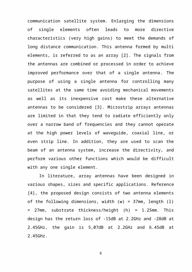
In [5], This paper presents the design of 4x4 rectangular patch array antenna for
the bore sight application of S-band tracking radar with the centre frequency of 2.73
GHz Individual patch having dimension of 43.6x35.3 mm with substrate of
permittivity 2.2 and thickness of 3.175 mm is used. Impedance bandwidth of 250 MHz
for VSWR less than 2 and gain of 18.4 dB with side lobe level better than -6.5 dB have
been achieved
Figure 1: Reference [5]
Research methodology:
In this paper, we have designed the microstrip array antennas with the slot
capable of working in the S-band from 2GHz to 4GHz. The resonant frequency
selected for our design is 2.96 GHz. The antenna is made of a thin substrate for the
application of conformal microstrip array antenna. This paper is proposes the
possibility of prototyping by design and analysis of microstrip array antennas 4×4 and
fabricated on FR-4 with dielectric constant is 4.4 (εr = 4.4).
5
2. Design and Simulation of the Antenna
Antenna requirements:
Frequency: S-band 3.0 GHz.
Bandwidth: 80-120 MHz
Directional
Simulation and Fabricate
Substrate: Fr4 Epoxy
Relative permittivity = ε r=4.4
h = 1.6 mm.
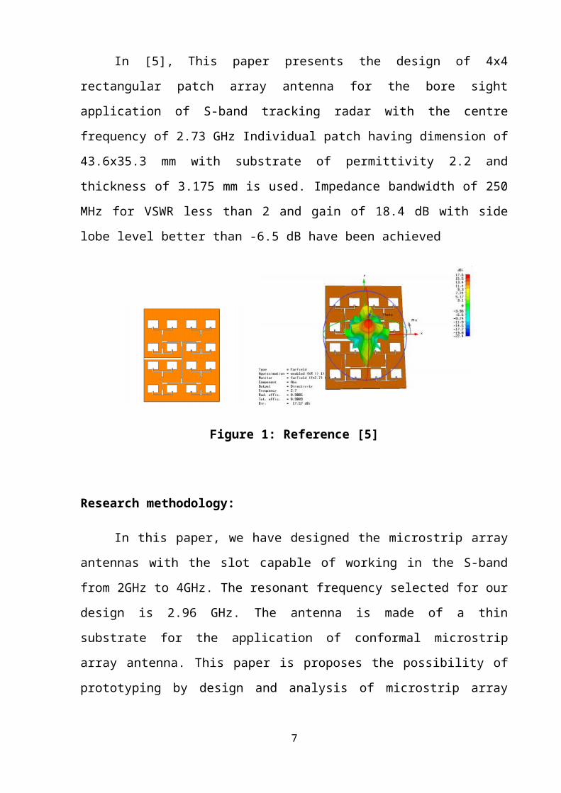
Rectangular Patch:
Figure 2: Microstrip line feed
Width of path
w= c
2 f r√( εr+2 )
2
Length (L)
6
L=Leff −2∆ L
Effective dielectric constant (ε reff ¿
ε reff=εr+1
2+
εr−12 [1+12
hw ]
−12
Effective length:
Leff =c
2 f r √εreff
Length extension
∆ L=0.412 h( εreff +0.3 )(w
h+0.264)
( εreff −0.3 )(wh
+0.813)Width of transmission line
w t=exp(Z0 (√ε r+1.41 )87 ) 0.8
5.98 h
Where:
f r=3.0 GHz (Resonant frequency).
h=1.6 mm (Thickness of substrate).
ε r=4.4 (Dielectric constant).
c=3.108 m /s (Speed of light).
z0=50 Ω (Impendence of transmission line).
The result is: w = 30mm, L = 23mm, w t = 2mm.
7

Figure 3: Singer patch
Feeding network
Figure 4: Feeding network
After calculated single path and feeding network, we have 4 x 4 elements array
antenna:
8
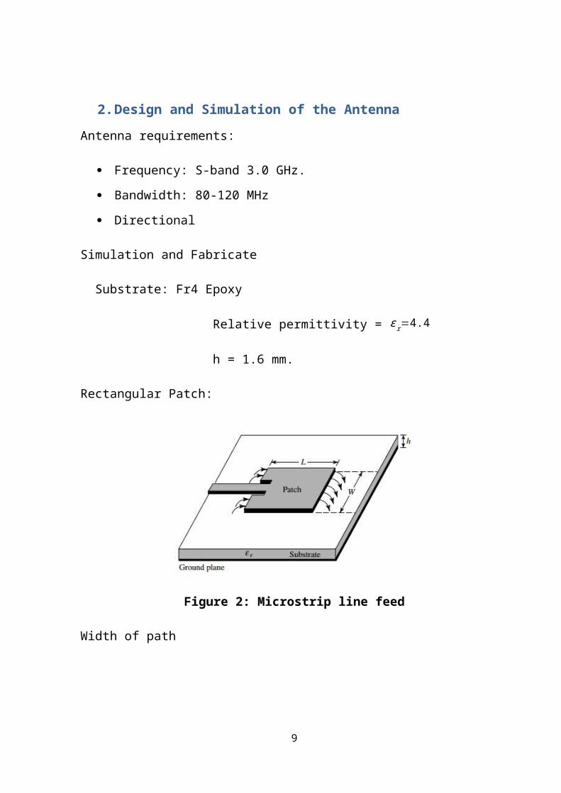
Figure 5: 4 x4 array atenna
Figure 6: Port and 3D model
3. Results and Discussions
The simulated antenna has been designed to work at S-band frequency of 2.96
GHz.Firstly, the simulated return loss of the microstrip antenna has been presented in
Figure :
9

Figure 7: Simulated return loss of the designed antenna
Table 1: Simulation results of return loss
Parameters Simulation Results
Resonant Frequency 2.96 MHz
Return loss -21.6 dB
Bandwidth at RL = -15
dB81 MHz (2.9GHz-2.981GHz)
As shown in Figure , good return loss result has been obtained, which is -21.6 dB at
2.96GHz. The approximately bandwidth is 81 MHz at RL = -15 dB has been archived.
Obviously, these results meet the requirements in terms of frequency range.
Secondly, the radiation pattern in 2D and 3D representation of the designed antenna
are shown in Figures 8, 9 and 10, respectively and the peak gain is 9.9 dB
10
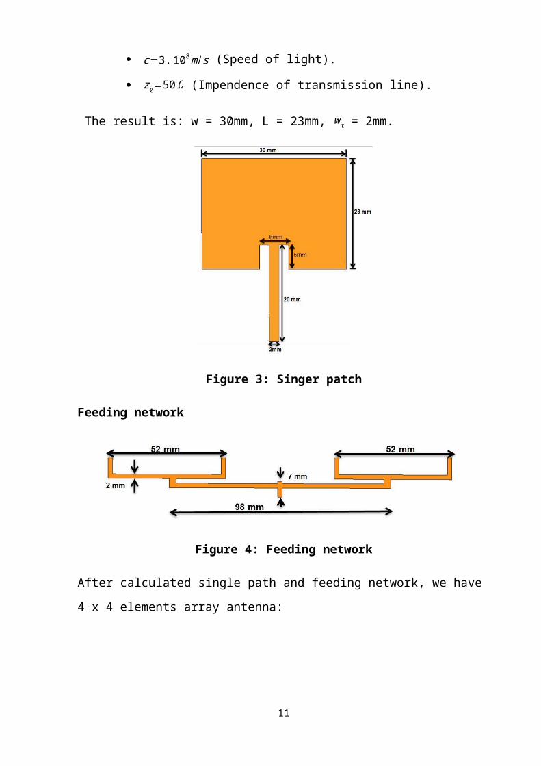
Figure 8: 2D radiation pattern (phi = 0 deg)
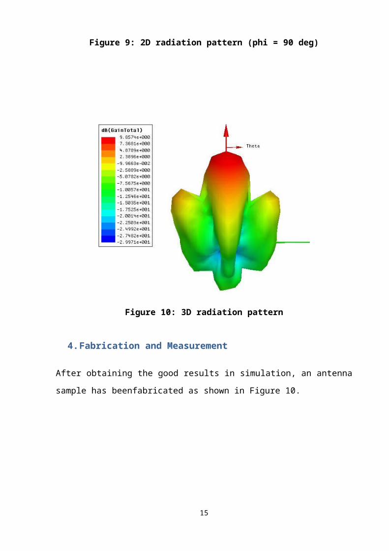
Figure 9: 2D radiation pattern (phi = 90 deg)
11
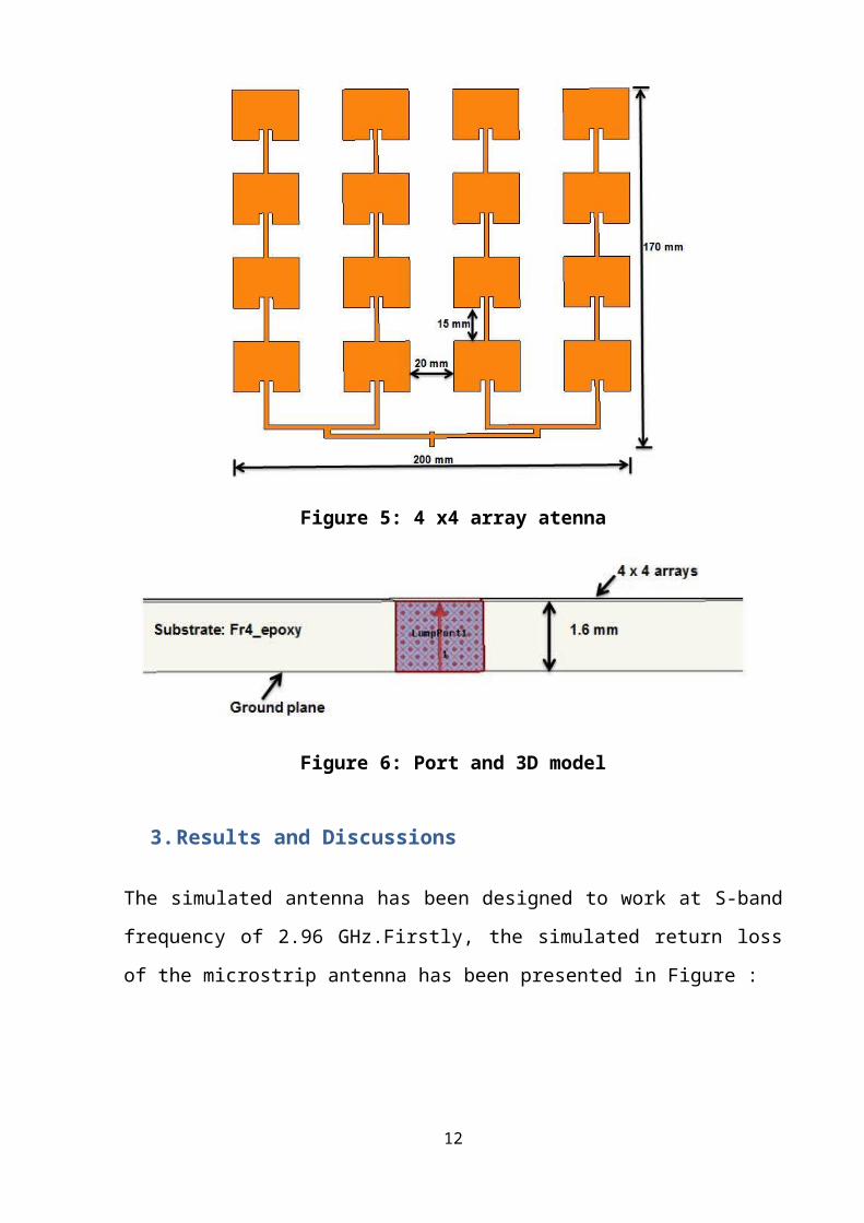
Figure 10: 3D radiation pattern
4. Fabrication and Measurement
After obtaining the good results in simulation, an antenna sample has beenfabricated
as shown in Figure 10.
Figure 11: Fabricated antenna
The antenna sample has been measured using the Vector Network Analyzer at the
Wireless Communications Department.
12

Figure 12: Connect the antenna to Network Analyzer
The measurement result of the return loss is shown in Figure 12
Figure 13: Comparison between the simulation results
and the measurement result of RL
13
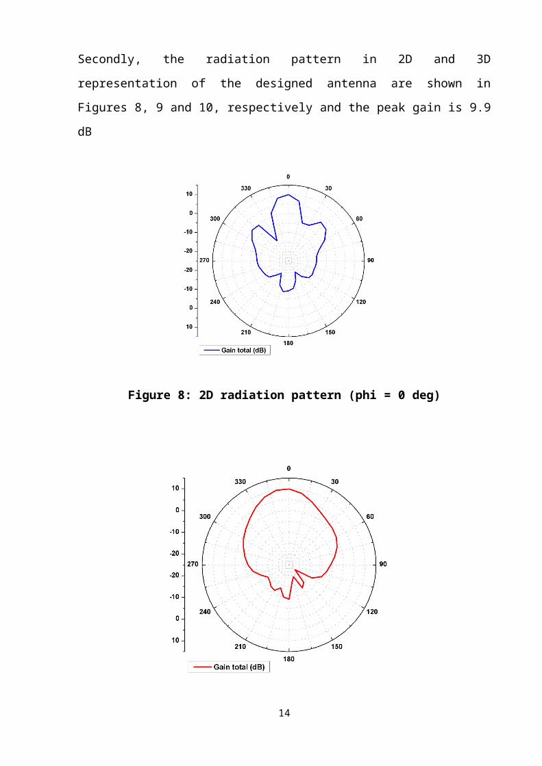
Table 2: Comparison between the simulation results and the measurement results
Simulation Measurement
Bandwidth at RL
=-15 dB
81 MHz
(2.9-2.91 GHz)
80 MHz
(2.96 – 3.04 GHz)
As can be seen in figure 13, the simulation and the measurement results have an
agreement. The differences between measurement and simulation are probably
because of some effects, such as the quality and the permittivity of the substrate and
the condition of the measurement.
5. Conclusions
A microstrip antenna S-band satellite communication systems which works at 2.45
GHz has been proposed.The antenna simulation has good results, which matched to
requirement of S-band. An antenna sample was fabricated and measured. The
simulation and measurement have been compared. A good agreement is given.The
designed antenna will befurther optimized to have better results.
REFERENCES
[1] http://www.nasa.gov/audience/forstudents/5-8/features/what-is-a-satellite-58.
14
[2] Antenna Theory - Analysis and Design_ Third Edition, Constantine A. Balanis.
[3] Salas Natera, M. A.; Martínez Rodríguez-Osorio, R.; Antón Sánchez, A.; García-
Rojo, I. & Cuellar, L. (2008). A3TB: Adaptive Antenna Array test-bed for tracking
LEO satellites based on software defined radio. 59th InternationalAstronautical
Congress, pp. 313-317, Glasgow. September 2008.
[4] T. K. Sreeja, A. Arun , Dr. J. Jaya Kumari .”An S-Band Micro-strip Patch Array
Antenna for nano-satellite applications”. Green Technologies (ICGT), 2012
International Conference on , 18-20 December 2012.
[5] Anila Kumar Sahu , Manas Ranjan Das “4X4 Rectangular Patch Array Antenna for
Bore Sight Application of Conical Scan S-band Tracking Radar”. Antenna Week
(IAW), 2011 Indian . 18-22 December 2011.
15