ARMY REsEARcH · PDF fileARMY REsEARcH LbORAORwY ... ELECTE OCT 1.5 1993 9E Aff'OVM FM MA=LI...
50
AD-A270 663 ARMY REsEARcH LbORAORwY • Blade and Hub Loads of Ballistically Damaged Helicopter Rotors Ki C. Kim ARL-TR-235 October 1993 DTIC ELECTE OCT 1.5 1993 9E Aff'OVM FM MA=LI UBL"EAS D11UXIflM 3 UNIM&MD 93-24081 "- -. -- "• 11 I"lll 'iilllllliill
Transcript of ARMY REsEARcH · PDF fileARMY REsEARcH LbORAORwY ... ELECTE OCT 1.5 1993 9E Aff'OVM FM MA=LI...
AD-A270 663
ARMY REsEARcH LbORAORwY •
Blade and Hub Loads ofBallistically Damaged Helicopter Rotors
Ki C. Kim
ARL-TR-235 October 1993
DTICELECTEOCT 1.5 1993
9E
Aff'OVM FM MA=LI UBL"EAS D11UXIflM 3 UNIM&MD
93-24081"- -. --"• 11 I"lll 'iilllllliill
NOTICES
Destroy this report when it Is no longer needed. DO NOT return it to the originator.
Additional copies of this report may be obtained from the National Technical InformationService, U.S. Department of Commerce, 5285 Port Royal Road, Springfield, VA 22161.
The findings of this report are not to be construed as an official Department of the Armyposition, unless so designated by other authorized documents.
The use of trade names or manufacturers' names in this report does not constituteindorsement of any commercial product.
Form APProvedREPORT DOCUMENTATION PAGE jo Nop.00-s
Pubijc reponrtnq burden for this collection of irformation is esltimated to aerage I •ouir pae respOirs Including ui e tim ltg review instructaonv, ,sar¢hng eiv'sng data ourtes.gatherIng and maintaining the data ncdd arid completing and renewing the collection of nformaton d S omnmein re~arding thi burde OtMatC Or any Other .,eecl Of thii ¢ollecion of ntotniiois. ,ncuding $uggeitions foT reducing this burden to Washington Headlquarter services. Directorate or information Operations and Reports. 12 is Jeffersoi
Davis High*ay. Suite 1204. Arlington. VA 22202-4302. and to the Office of Management and Budget. Paperwork Reduction Proget (070•-0189). Washington. DC 20SO0
1. AGENCY USE ONLY (Leave blank) 2. REPORT DATE 3. REPORT TYPE AND DATES COVERED
I cober 1993 Final. 1992- May 94. TITLE AND SUBTITLE S. FUNDING NUMBERS
Blade and Hub Loads of Ballistically Damaged Heicopter RotorsPR. IL162618AH80
6. AUTHOR(S)
Ki C. Kim
7. PERFORMING ORGANIZATION NAME(S) AND ADDRESS(ES) B. PERFORMING ORGANIZATIONREPORT NUMBER
U.S. Army Research LaboratoryATM.: AMSRL-SL-BAAberdeen Proving Ground, MD 21005-5068
9. SPONSORING/MONITORING AGENCY NAME(S) AND ADDRESS(ES) 10. SPONSORING/MONITORINGAGENCY REPORT NUMBER
U.S. Army Research LaboratoryATfN: AMSRL-OP-CI-B (Tech Lib) ARL-TR-235Aberdeen Proving Ground, MD 21005-5066
11. SUPPLEMENTARY NOTES
12a. DISTRIBUTION /AVAILABILITY STATEMENT 12b. DISTRIBUTION CODE
Approved for public release; distribution is unlimited.
13. ABSTRACT (Maximum 200 words)
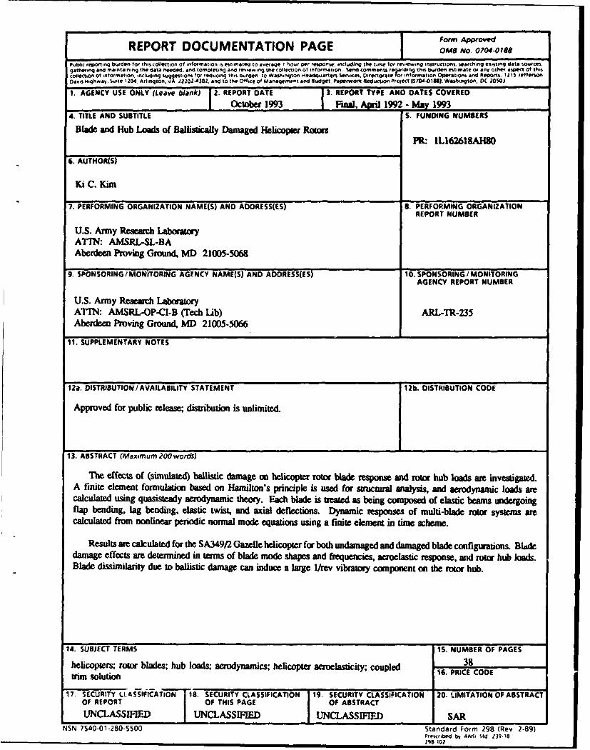
The effects of (simulated) ballistic damage on helicopter rotor blade response and rotor hub loads am investigated.A finite element formulation based on Hamilton's principle is used for structral analysis, and aerodynamic loads arecalculated using quasisteady aerodynamic theory. Each blade is treated as being composed of elastic beams undergoingflap bending, lag bending, elastic twist, and axial deflections. Dynamic responses of multi-blade rator systems arecalculated from nonlinear periodic normal mode equations using a finite element in time scheme.
Results are calculated for the SA349/2 Gazelle helicopter for both undamaged and damaged blade configurations. Bladedamage effects are determined in terms of blade mode shapes and frequencies, aeroelastic response, and rotor hub loads.Blade dissimilarity due to ballistic damage can induce a large I/rev vibratory component on the rotor hub.
14. SUBJECT TERMS 15. NUMBER OF PAGES
helicopters; rotor blades; hub loads; aerodynamics; helicopter aeroelasticity; coupled 38tm solution 16. PRICE CODE
17. SECURITY LLASSIFICATION 18. SECURITY CLASSIFICATION 19. SECURITY CLASSIFICATION 20. LIMITATION OF ABSTRACTOF REPORT OF THIS PAGE OF ABSTRACT
UNCLASSIFIED UNCLASSIFIED 1 UNCLASSIFIED SARNSN 7540-01-280-5500 Standard Form 298 (Rev 2-89)
Pre-scribed by ANSi Std 139- 18
298-102

INTENTIONALLY LEFT BLANK.
Table of ContentsPage
List of Figures ........... ............................................... v
List of Tables ............ ................................................ vii
Acknowledgment ........... .............................................. ix
Nomenclature.......................................................... xi
I. Introduction ............. .............................................. I
1. Background ........... .......................................... I
2. Present Study .................................................. 2
II. Formulation ............ .............................................. 3
1. Coupled Trim Analysis ............................................ 4
2. Vehicle Trim .......... ......................................... 4
3. Rotor Dynamic Response ......... .................................. 6
4. Rotor Wake Modeling ......... .................................... 6
I1I. Solution Procedure .......... .......................................... 6
IV. Results and Discussion .......... ........................................ 7
1. Baseline (Undamaged) Helicopter: Correlation Study ........................ 9
2. Helicopter with Damaged Blade ......... .............................. 9
V. Conclusions ............ .............................................. I I
VI. References ........... ............................................... 21
Appendix A: UMARC Input Data Set ......... .................................. 23
Appendix B: Sample Gazelle Input Data .............................. ........ 27
D-iAccesion ForDistribution List . . . ................. N. . NTiS " A&I ' " ........... ... 31
DTIC TABUnannounced 0Justification.
IJIX ~By ......Distribution I
Availability Codes
Avail and I oruist Special
iii

INTENTIONALLY LEFT BLANK.
iv
List of FiguresFigure Page
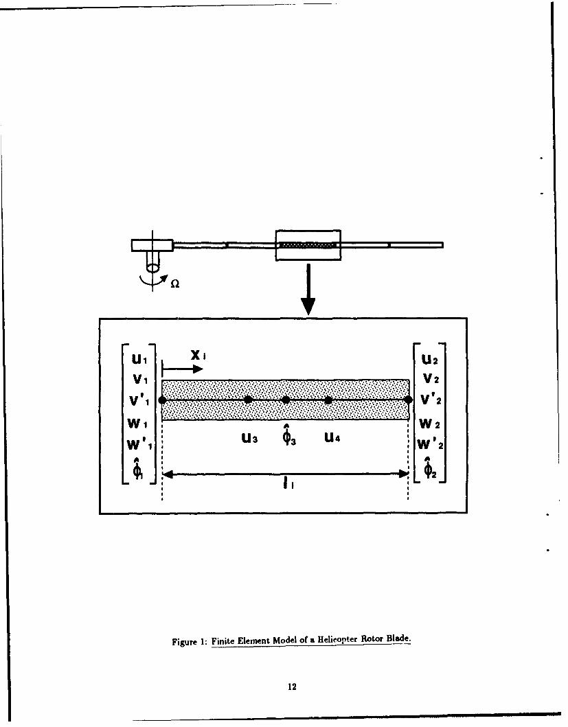
1 Finite Element Model of a Helicopter Rotor Blade ................................ 12
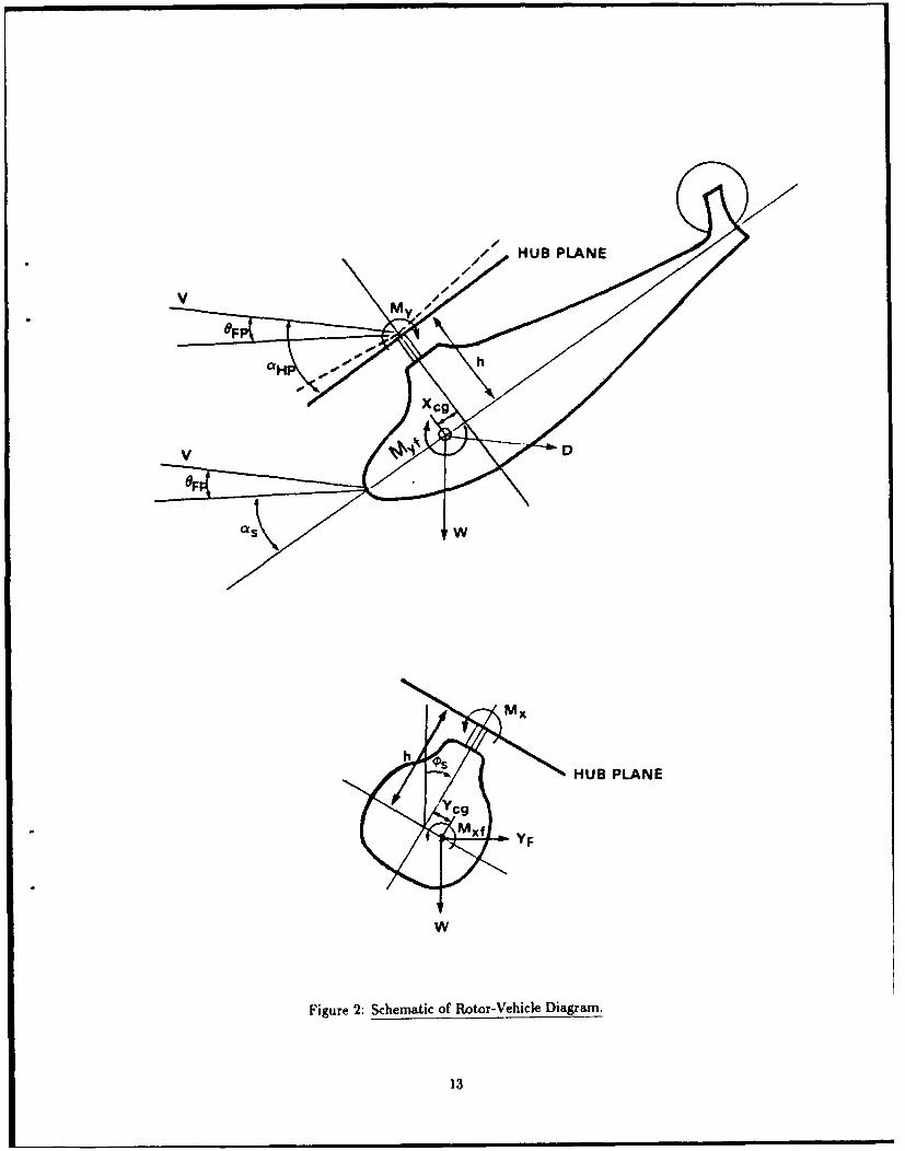
2 Schematic of Rotor-Vehicle Diagram ......................................... 13
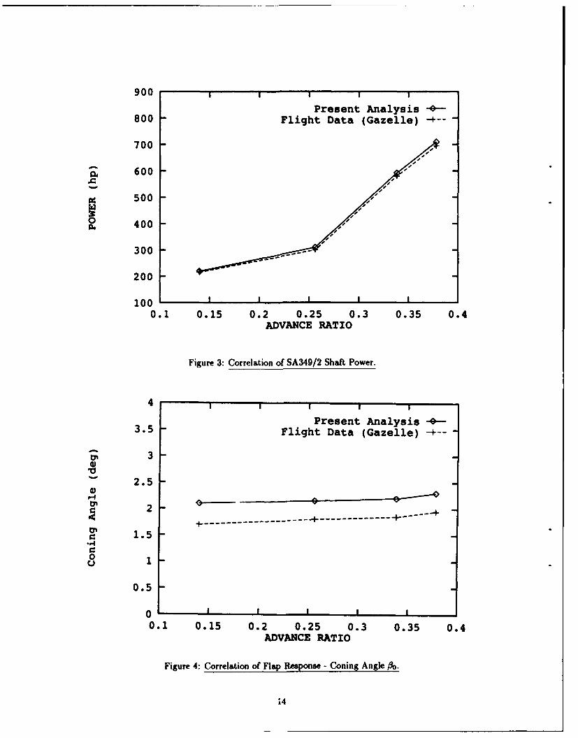
3 Correlation of SA349/2 Shaft Power ......................................... 14
4 Correlation of Flap Response - Coning Angle ....... .......................... 14
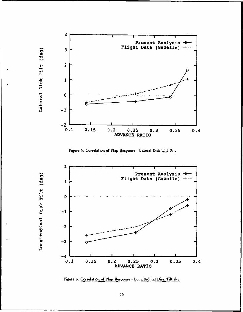
5 Correlation of Flap Response - Lateral Disk Tilt 61 .............................. 15
6 Correlation of Flap Response - Longitudinal Disk Tilt flit ........................... 15
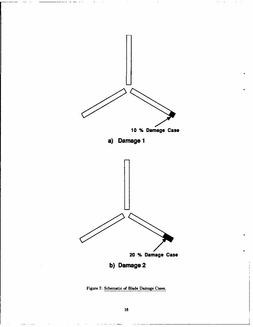
7 Schematic of Blade Damage Cases ........................................... 16
8 First Flap Mode Shapes of Undamaged and Damaged Blades ........................ 17
9 Second Flap Mode Shapes of Undamaged and Damaged Blades ....................... 17
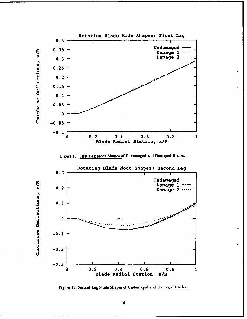
10 First Lag Mode Shapes of Undamaged and Damaged Blades ........................ 18
11 Second Lag Mode Shapes of Undamaged and Damaged Blades ........................ 18
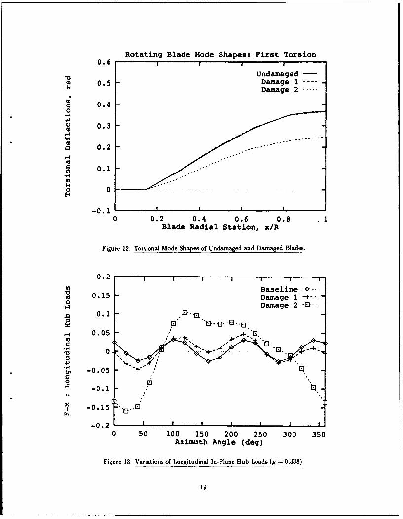
12 Torsional Mode Shapes of Undamaged and Damaged Blades ........................ 19
13 Variations of Longitudinal In-Plane Hub Loads (p = 0.338) .......................... 19
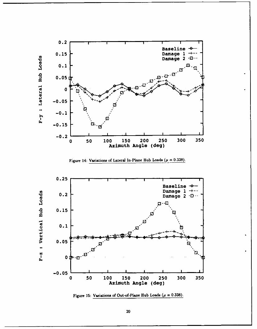
14 Variations of Lateral In-Plane Hub Loads (p = 0.338) .................. ......... 20
15 Variations of Out-of-Plane Hub Loads (p = 0.338) ................................ 20
V

INTENTIONALLY LEFT BLANK.
vi
List of TablesTable Page
I SA349/2 Gazelle Helicopter Characteristics ............................. 8
2 Structural Properties of Gazelle Rotor Blade ................................... 8
3 Aerodynamic Deficiency Functions of Damaged Airfoil ............................. 10
4 Frequencies of Damaged Blades (per rev) ..................................... 10
vii

INTENTIONALLY LEFT BLANK.
viii

Acknowledgment
The author would like to to express gratitude to Mr. Stephen F. Polyak, a team leaderof Engineering Analysis Team (EAT) in the Air Systems Branch (ASB) of the US ArmyResearch Laboratory (ARL), for his invaluable support during the course of this research.The author would also like to thank Dr. James N. Walbert, a chief of Air Systems Branch(ASB) of ARL, for his support.
ix
INTENTIONALLY LEFT BLANK.
x
Nomenclature
c Blade chord.
co Lift coefficient at zero angle of attack.
C1 Lift curve slope.
Cd Blade section drag coefficient.
C1 Blade section lift coefficient.
CmC Blade section pitching moment coefficient about aerodynamic center.
CDo Fuselage drag coefficient.
Cif Fuselage rolling moment coefficient.
CLI Fuselage lift coefficient.
Cm; Fuselage pitching moment coefficient.
C,•t Fuselage yawing moment coefficient.
CQ Rotor-shaft torque coefficient.
C,, Helicopter weight coefficient.
do Viscous drag coefficient.
di, d2 Pressure drag coefficients.
DF Fuselage drag.
EI Flap-wise bending stiffness.
ElI Chord-wise bending stiffness.
fo, fl Pitching moment coefficients.
GJ Effective sectional torsional stiffness.
h Vertical distance from helicopter c.g. to hub center.
I, Length of the ith beam element.
xi
rn Blade section mass.
M Mach number.
minc Incident Mach number normal to chord.
mo Reference blade section mass.
Nb Blade number.
q Global displacement vector.
R Blade radius.
T Rotor thrust.
u Blade displacement in the axial direction.
v Blade displacement in the lead-lag direction.
V Helicopter forward speed.
w Blade displacement in the flap-wise direction.
Xcg, YCg Hub center position relative to helicopter c.g. in
the X and Y directions, respectively.
Xt Distance between main rotor hub and tail rotor hub.
YF Fuselage side force.
YtIr Tail rotor thrust.
a Blade section angle of attack.
alip Hub plane tilt angle relative to flight direction.
a, Longitudinal shaft tilt relative to wind axis.
16 Rotor coning angle.
0., #1 C Lateral and longitudinal disk tilt angle, respectively.
f1, lid, 1m Aerodynamic deficiency functions because of blade damage.
xii
0 hli 01. Lateral and longitudinal cyclic trim inputs, respectively.
0.75 Collective blade pitch at 0.75% radius.
OFP Helicopter flight path angle relative to the longitudinal axis.
p Advance ratio.
a Rotor solidity ratio.
Blade twist.
Lateral shaft tilt.
11 Rotor rotational speed.
xiii

INTENTIONALLY LEFT BLANK.
xiv
I. Introduction
1. Background
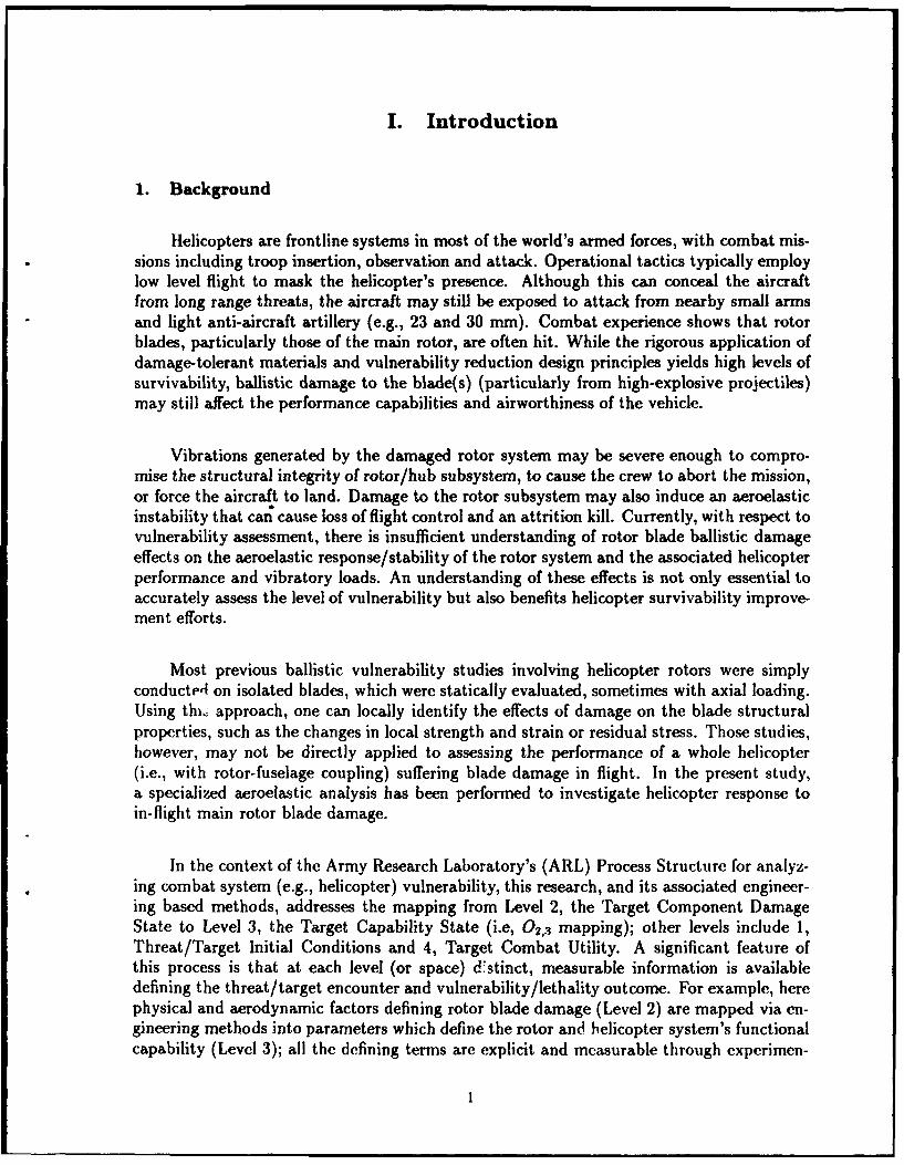
Helicopters are frontline systems in most of the world's armed forces, with combat mis-sions including troop insertion, observation and attack. Operational tactics typically employlow level flight to mask the helicopter's presence. Although this can conceal the aircraftfrom long range threats, the aircraft may still be exposed to attack from nearby small armsand light anti-aircraft artillery (e.g., 23 and 30 mm). Combat experience shows that rotorblades, particularly those of the main rotor, are often hit. While the rigorous application ofdamage-tolerant materials and vulnerability reduction design principles yields high levels ofsurvivability, ballistic damage to the blade(s) (particularly from high-explosive projectiles)may still affect the performance capabilities and airworthiness of the vehicle.
Vibrations generated by the damaged rotor system may be severe enough to compro-mise the structural integrity of rotor/hub subsystem, to cause the crew to abort the mission,or force the aircraft to land. Damage to the rotor subsystem may also induce an aeroelasticinstability that car; cause loss of flight control and an attrition kill. Currently, with respect tovulnerability assessment, there is insufficient understanding of rotor blade ballistic damageeffects on the aeroelastic response/stability of the rotor system and the associated helicopterperformance and vibratory loads. An understanding of these effects is not only essential toaccurately assess the level of vulnerability but also benefits helicopter survivability improve-ment efforts.
Most previous ballistic vulnerability studies involving helicopter rotors were simplyconducted on isolated blades, which were statically evaluated, sometimes with axial loading.Using thiQ approach, one can locally identify the effects of damage on the blade structuralproperties, such as the changes in local strength and strain or residual stress. Those studies,however, may not be directly applied to assessing the performance of a whole helicopter(i.e., with rotor-fuselage coupling) suffering blade damage in flight. In the present study,a specialized aeroelastic analysis has been performed to investigate helicopter response toin-flight main rotor blade damage.
In the context of the Army Research Laboratory's (ARL) Process Structure for analyz-ing combat system (e.g., helicopter) vulnerability, this research, and its associated engineer-ing based methods, addresses the mapping from Level 2, the Target Component DamageState to Level 3, the Target Capability State (i.e, 02,3 mapping); other levels include 1,Threat/Target Initial Conditions and 4, Target Combat Utility. A significant feature ofthis process is that at each level (or space) d*stinct, measurable information is availabledefining the threat/target encounter and vulnerability/lethality outcome. For example, herephysical and aerodynamic factors defining rotor blade damage (Level 2) are mapped via en-gineering methods into parameters which define the rotor and helicopter system's functionalcapability (Level 3); all the defining terms are explicit and measurable through experimen-
1
tation. Note also that ambient (e.g, air density) and operating factors (e.g., forward flightvelocity) (defined at Level 1) are accounted for in the methodology and provide realisticvariable scenario capability. Application of these and other engineering analysis tools to theVulnerability/Lethality Process Structure will occur largely through implementation in theDegraded States Vulnerability Methodology for level 02,3 mapping now under developmentfor aircraft targets at ARL.
2. Present Study
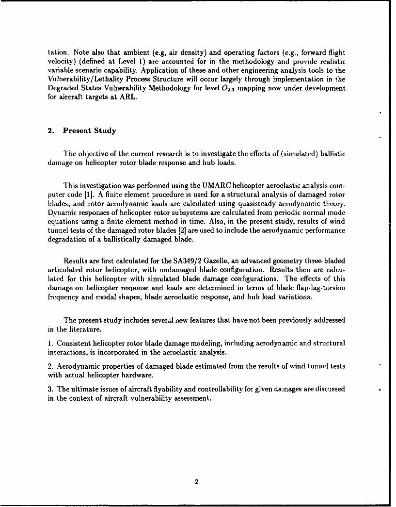
The objective of the current research is to investigate the effects of (simulated) ballisticdamage on helicopter rotor blade response and hub loads.
This investigation was performed using the UMARC helicopter aeroelastic analysis com-puter code [1]. A finite element procedure is used for a structural analysis of damaged rotorblades, and rotor aerodynamic loads are calculated using quasisteady aerodynamic theory.Dynamic responses of helicopter rotor subsystems are calculated from periodic normal modeequations using a finite element method in time. Also, in the present study, results of windtunnel tests of the damaged rotor blades [2] are used to include the aerodynamic performancedegradation of a ballistically damaged blade.
Results are first calculated for the SA349/2 Gazelle, an advanced geometry three-bladedarticulated rotor helicopter, with undamaged blade configuration. Results then are calcu-lated for this helicopter with simulated blade damage configurations. The effects of thisdamage on helicopter response and loads are determined in terms of blade flap-lag-torsionfrequency and modal shapes, blade aeroelastic response, and hub load variations.
The present study includes severJ new features that have not been previously addressedin the literature.
1. Consistent helicopter rotor blade damage modeling, including aerodynamic and structuralinteractions, is incorporated in the aeroelastic analysis.
2. Aerodynamic properties of damaged blade estimated from the results of wind tunnel testswith actual helicopter hardware.
3. The ultimate issues of aircraft flyability and controllability for given damages are discussedin the context of aircraft vulnerability assessment.
2
II. Formulation
The baseline helicopter aeroelastic code used in this investigation is a comprehensiveaeroelastic analysis based on finite element theory in space and time [1].
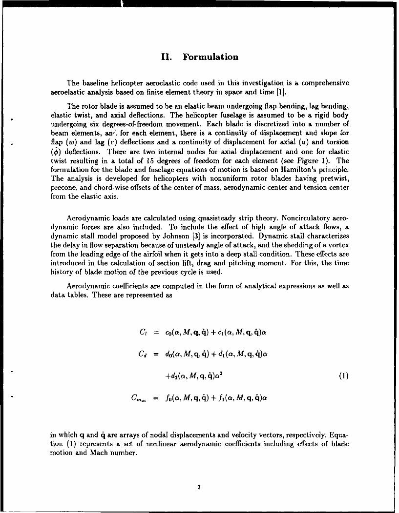
The rotor blade is assumed to be an elastic beam undergoing flap bending, lag bending,elastic twist, and axial deflections. The helicopter fuselage is assumed to be a rigid bodyundergoing six degrees-of-freedom movement. Each blade is discretized into a number ofbeam elements, anl for each element, there is a continuity of displacement and slope forflap (w) and lag (u) deflections and a continuity of displacement for axial (u) and torsion(•) deflections. There are two internal nodes for axial displacement and one for elastictwist resulting in a total of 15 degrees of freedom for each element (see Figure 1). Theformulation for the blade and fuselage equations of motion is based on Hamilton's principle.The analysis is developed for helicopters with nonuniform rotor blades having pretwist,precone, and chord-wise offsets of the center of mass, aerodynamic center and tension centerfrom the elastic axis.
Aerodynamic loads are calculated using quasisteady strip theory. Noncirculatory aero-dynamic forces are also included. To include the effect of high angle of attack flows, adynamic stall model proposed by Johnson [3] is incorporated. Dynamic stall characterizesthe delay in flow separation because of unsteady angle of attack, and the shedding of a vortexfrom the leading edge of the airfoil when it gets into a deep stall condition. These effects areintroduced in the calculation of section lift, drag and pitching moment. For this, the timehistory of blade motion of the previous cycle is used.
Aerodynamic coefficients are computed in the form of analytical expressions as well asdata tables. These are represented as
C1 = co(a,M,q,4)+cj(a,M,q,4j)a
Cd = do(a,M,q,4)+di(a,M,q,4j)a
+d2 (a, M, q, 4~)Q2(1
Cmoe = fo(a, M, q, 4) + fi(a, M, q, 4)a
in which q and q are arrays of nodal displacements and velocity vectors, respectively. Equa-tion (1) represents a set of nonlinear aerodynamic coefficients including effects of blademotion and Mach number.
3
1. Coupled Trim Analysis
The coupled trim analysis consists of two phases, vehicle trim and steady response,calculated as one coupled solution using a modified Newton method. For a given flight con-dition, the control settings and the blade steady response must satisfy both the blade and thevehicle equilibrium conditions. The method of solving simultaneously the blade responsesand the trim control settings is referred to as the coupled trim analysis. An uncoupled trimsolution based on the rigid flapping blade assumption is used as an initial estimate for thecoupled trim analysis. With the trim control settings, the blade steady responses are calcu-lated. Using the blade responses, the rotor hub loads and a new vehicle equilibrium positionare recomputed. The control settings are then updated based on the new equilibrium con-dition.
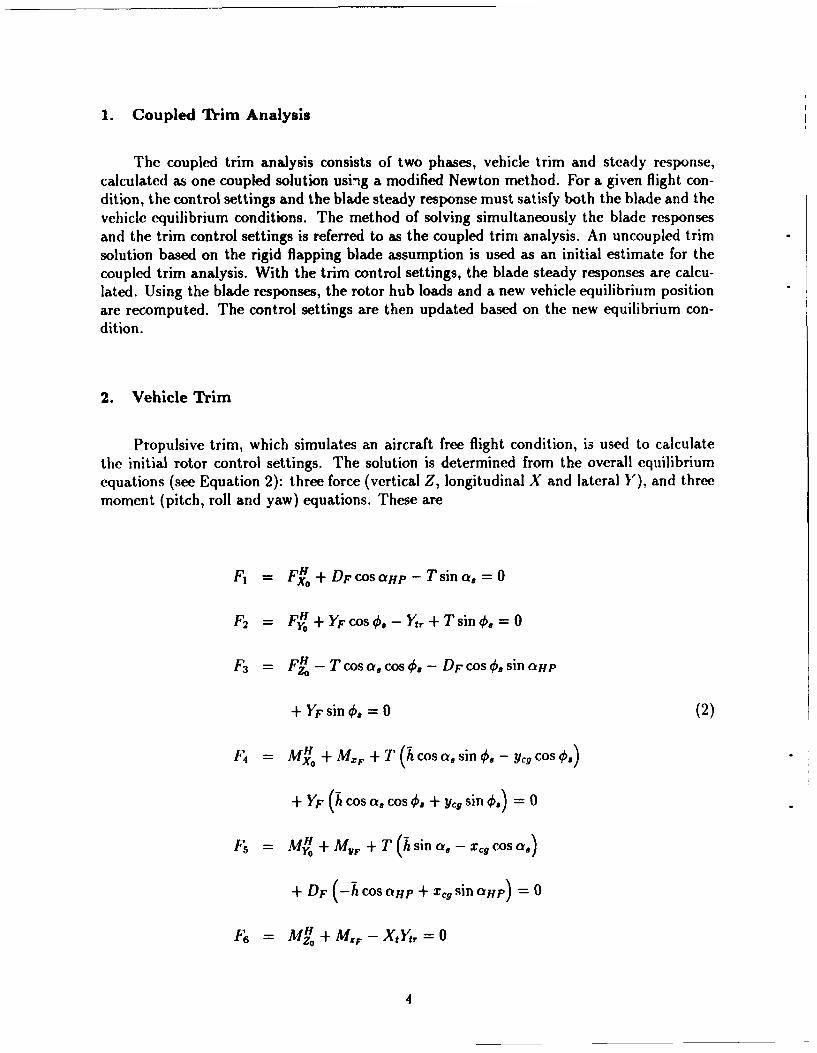
2. Vehicle Trim
Propulsive trim, which simulates an aircraft free flight condition, is used to calculatethe initial rotor control settings. The solution is determined from the overall equilibriumequations (see Equation 2): three force (vertical Z, longitudinal X and lateral Y), and threemoment (pitch, roll and yaw) equations. These are
F, = F H + DF cos allp - Tsina, = 0
F2 = FH +YFcoso. - Ytr + T sin .=O
F3 = F -Tcos cos a . - DF cos €sin oP
+ YF sin . =0 (2)
F4 = MH + MXF+ T(h COSasin B ygCcOS~I
+ YF (h COS cra COS 0. + Yg sin =0
Fs =MH + MvF+ T (h sin a, -xC COS a,
+ DF H CoS .HP + X ., sin aHp) =0
F6 = MH + M.F - XtYt,=0
4
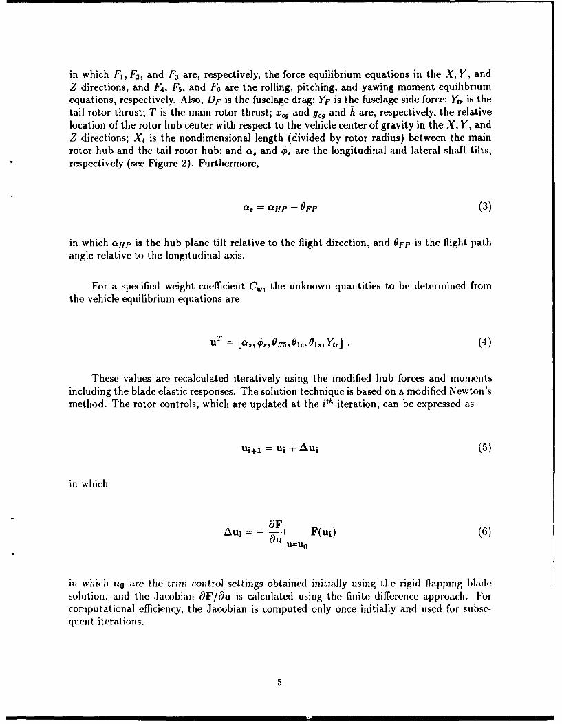
in which F1 , F2, and F3 are, respectively, the force equilibrium equations in the X, Y, andZ directions, and F4, F5 , and F6 are the rolling, pitching, and yawing moment equilibriumequations, respectively. Also, DF is the fuselage drag; YF is the fuselage side force; Yt, is thetail rotor thrust; T is the main rotor thrust; xC9 and ycg and h are, respectively, the relativelocation of the rotor hub center with respect to the vehicle center of gravity in the X, Y, andZ directions; Xt is the nondimensional length (divided by rotor radius) between the mainrotor hub and the tail rotor hub; and a, and 0, are the longitudinal and lateral shaft tilts,respectively (see Figure 2). Furthermore,
as = allp - OFP (3)
in which aHp is the hub plane tilt relative to the flight direction, and OFP is the flight pathangle relative to the longitudinal axis.
For a specified weight coefficient C,,, the unknown quantities to be determined fromthe vehicle equilibrium equations are
uT= L0, 0.75,O0c,01o, 0,° J (4)
These values are recalculated iteratively using the modified hub forces and momentsincluding the blade elastic responses. The solution technique is based on a modified Newton'smethod. The rotor controls, which are updated at the ith iteration, can be expressed as
u1+1 = u! + Aui (5)
in which
AuF F(ui) (6)Aui ~ ~ I uU=Uo
in which uO are the trim control settings obtained initially using the rigid flapping bladesolution, and the Jacobian MF/au is calculated using the finite difference approach. Forcomputational efficiency, the Jacobian is computed only once initially and used for subse-quent iterations.
5
3. Rotor Dynamic Response
The rotor dynamic response involves the determination of time-dependent blade po-sitions at different azimuth locations for one rotor revolution. To reduce computationaltime, the finite element equations are transformed into modal space as a few normal modeequations using the coupled natural vibration characteristics of the blade. These nonlinearperiodic coupled equations are solved for steady response using a finite element in time pro-cedure based on Hamilton's principle in weak form [4]. One rotor revolution is divided into anumber of azimuthal elements, and then periodicity of response is used to join the motions ofthe first and last elements. The assembly of elements results in nonlinear algebraic equationsthat are solved using the Newton-Raphson procedure.
After the blade response is obtained, hub forces and moments are calculated using theforce summation method. These values are finally used to recalculate the coupled trim con-trol values.
4. Rotor Wake Modeling
For the induced in-flow distribution on the rotor disk, a free wake model [5] is fullycoupled in the rotor aeroelastic analysis. The model can account for wake self-distortion byupdating its geometry according to newly calculated in-flow and blade circulation distribu-tions. The geometry of the free wake is divided into three regions: near wake, rolling upwake, and far wake. The near wake consists of a series of radial panels, each with linearcirculation distributions. The rolling up wake consists of an in-board linear circulation dis-tribution panel, and a tip panel that represents the rolling up of the tip vortex. The far wakeis modeled as one panel with a linear circulation distribution, and a concentrated tip vortexwhose strength is proportional to the maximum circulation value on the rotor blade. Thehelical geometry of the concentrated tip vortex is updated while the in-board wake portionsare not changed.
The free wake analysis is implemented in three stages. First, blade motion and loadingare calculated using a linear in-flow model. Next, wake-induced coefficients are calculatedfor an undistorted wake geometry. The nonuniform in-flow is calculated and is used toobtain blade motion and loading. Finally, the free wake geometry is calculated. For this, theinfluence coefficients are re-evaluated, and blade motion and loading are again obtained usingnonuniform in-flow values. For subsequent iterations, the free wake geometry is generallyheld fixed, and only the strength of vortices is updated.
III. Solution Procedure
The following procedure was used to study the simulated ballistic damaged effects onhelicopter rotor response and loads in forward flight conditions.
1. With prescribed input data, vehicle trim equations are calculated using rigid bladeflapping (a starting point).
2. Using control inputs from the vehicle trim solution of Step 1 and prescribed bladedamage condition, the blade nonlinear steady response is calculated. The results give de-tailed individual blade responses at different span-wise and azimuthal positions.
3. Hub loads and moments are calculated using elastic rotor responses. Then, thevehicle trim values and blade responses are recalculated iteratively using the modified hubforces and moments. This step is repeated until a converged solution is obtained.
4. Steps of 2 to 3 are repeated for different damage configurations.
IV. Results and Discussion
Numerical results are first calculated for a undamaged (baseline) rotor of the SA349/2Gazelle helicopter for level flight conditions. Results then are calculated for this rotor withsimulated damaged conditions and the effects of blade damages are assessed. Some of im-portant structural and aerodynamic characteristics of this helicopter rotor are given in Table1. Other characteristics of this helicopter are given in Reference 6.
The SA349/2 Gazelle helicopter was fitted with an advanced geometry three-bladedarticulated rotor. The Grande Vitesse (GV) blades consisted of OA209 advanced airfoils(9% thickness ratio), adjustable tips, and nonlinear twist distributions.
In the present study, an effort was made to model the helicopter blade characteristicsas accurately as possible. The structural properties of blades obtained from the measureddata [6] were used for blade finite element model (see Table 2). Nonlinear twist distributionof the blade was also modeled in the blade finite elements. One of the main features in thisarticulated rotor blade is a lag damper. The lag damper can significantly affect the bladedynamics. In the present analysis, additional stiffness as well as damping tbrms attributableto the lag damper were included.
For the calculation of blade dynamic response, each rotor blade is discretized into eightbeam elements, and each beam element consists of 15 nodal degrees of freedom. For normalmode reduction, five coupled rotating natural modes are used, comprised of two flaps, twolags, and one torsion mode. For periodic response, one cycle of time is discretized into eighttime elements, and each time element represents a fifth order polynomial distribution ofmotion.
7
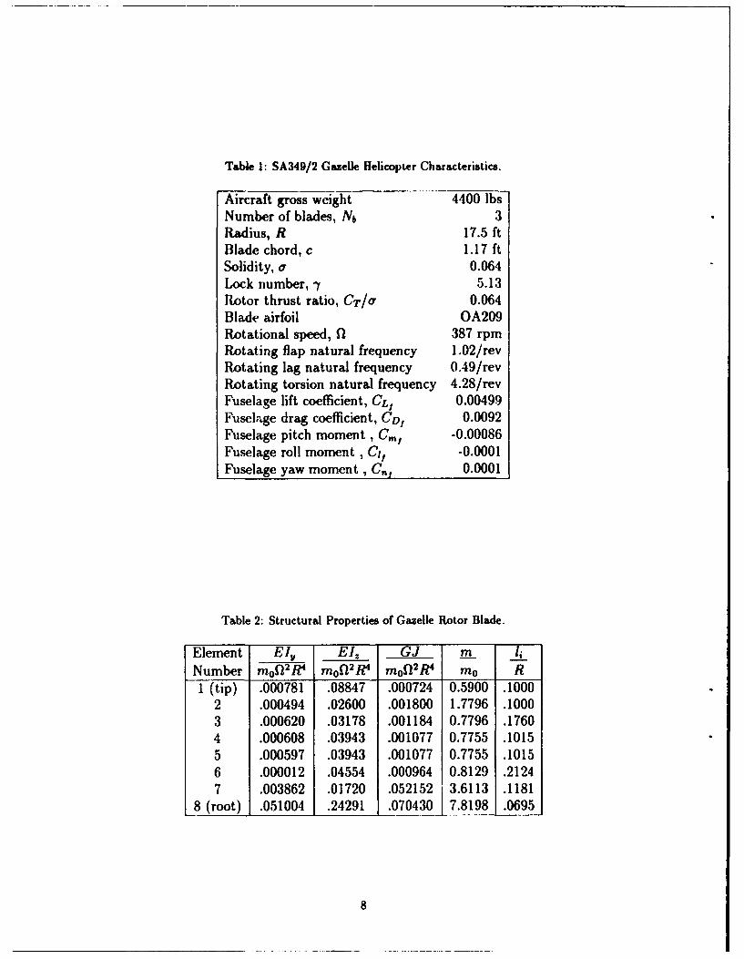
Table 1: SA349/2 Gazelle Helicopter Characteristics.
Aircraft gross weight 4400 lbsNumber of blades, Nb 3Radius, R 17.5 ftBlade chord, c 1.17 ftSolidity, a 0.064Lock number, - 5.13Rotor thrust ratio, CT/cl 0.064Blade airfoil OA209Rotational speed, fl 387 rpmRotating flap natural frequency 1.02/revRotating lag natural frequency 0.49/revRotating torsion natural frequency 4.28/revFuselage lift coefficient, CL, 0.00499Fuselage drag coefficient, CD, 0.0092Fuselage pitch moment, Cm, -0.00086Fuselage roll moment , Cif -0.0001Fuselage yaw moment, C,,, 0.0001
Table 2: Structural Properties of Gazelle Rotor Blade.
Element E4I E l. G J m 1,.
Number rnof•2 W m0ol 2 R mof(2 /R mo R1 (tip) .000781 .08847 .000724 0.5900 .1000
2 .000494 .02600 .001800 1.7796 .10003 .000620 .03178 .001184 0.7796 .17604 .000608 .03943 .001077 0.7755 .10155 .000597 .03943 .001077 0.7755 .1015
6 .000012 .04554 .000964 0.8129 .21247 .003862 .01720 .052152 3.6113 .1181
8 (root) .051004 .24291 .070430 7.8198 .0695
8
1. Baseline (Undamaged) Helicopter: Correlation Study
To validate the coupled trim procedure used in the present study, calculated trim valuesof baseline (undamaged) helicopter are correlated with existing flight test data [61 for fourlevel flight conditions (advance ratio p = 0.14, 0.256, 0.333, 0.378).
Figure 3 shows the correlation of the power requirement to maintain the level flight ofthe helicopter. The torque coefficient (CQ) obtained from the coupled trim solution was usedto calculate shaft power. The quasi-steady aerodynamics with the free wake model are usedfor the entire flight envelope. Excellent correlations with flight test data are observed.
The blade flapping angles are also correlated with flight data and shown in Figures 4through 6. Calculated blade flap responses at the tip, in terms of the coning angle (1O)and the rotor disk tilt angles (f31,, 01.), are compared with the data for four flight condi-tions. Reasonably good agreement with test data was observed, providing the author witha certain confidence in the helicopter rotor subsystem model constructed in the present study.
In the following sectiorn, results are calculated for the helicopter damaged on its rotorblade, and then blade damage effects on blade and hub loads are assessed.
2. Helicopter with Damaged Blade
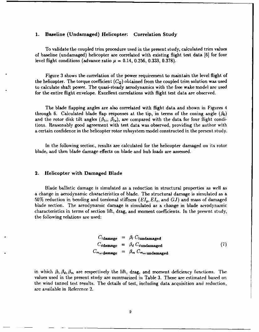
Blade ballistic damage is simulated as a reduction in structural properties as well asa change in aerodynamic characteristics of blade. The structural damage is simulated as a50% reduction in bending and torsional stiffness (EIl, EI,, and GJ) and mass of damagedblade section. The aerodynamic damage is simulated as a change in blade aerodynamiccharacteristics in terms of section lift, drag, and moment coefficients. In the present study,the following relations are used:
Cidamage = A! Clundamaged
Cddamage = Od Cdundamaged (7)Cmad..aage = & C-aeundanmged
in which 0i1, Id, 0'm are respectively the lift, drag, and moment deficiency functions. Thevalues used in the present study are summarized in Table 3. These are estimated based onthe wind tunnel test results. The details of test, including data acquisition and reduction,are available in Reference 2.
9
Table 3: Aerodynamic Deficiency Functions of Damaged Airfoil.
Deficiency Functions Mi,,1 <_ 0.7 M,,c > 0.7A•l 0.75 0.7
'I1-M 22.513d 2.5 V1 _M2
_0.9 0.9
Table 4: Frequencies of Damaged Blades (per rev).
Mode Baseline Damage I Damage 2First Lag 0.492 0.575 0.856First Flap 1.016 1.048 1.181
Second Flap 2.694 2.783 2.923First Torsion 4.289 4.460 4.438Second Lag 4.611 4.768 5.056
In the present study, two different blade damage conditions are considered: Damage1 and Damage 2. Damage 1 represents a condition in which 10% of the outboard blade tipof one blade is damaged, resulting the reduction in structural and aerodynamic capabilityof that blade section. Damage 2 represents a more severe damage condition, in which 20%of the outboard section is damaged (see Figure 7).
Effects of the simulated damages on the blade natural frequencies are summarized inTable 4, and the corresponding mode shapes are shown in Figures 8 through 12. The resultsof baseline (undamaged) blade are shown, along with two damage cases. It is shown that theblade damage affects all the modes of the blades. Of particular interest is the behavior ofthe fundamental lag frequency of the blade, since the lag motion is very important in bladedynamic study. As the size of the damage (%) increases, the Irequency of the first lag modeis increased. This is thought to be caused by changes in the centrifugal force due to blademass/stiffness effects. The torsional mode shape of the 20% tip damaged blade (Damage 2)is quite different from that of baseline and Damage 1 (see Figure 12). This is because of alarge coupling effect between the second lag and the first torsional modes.
Most of the comprehensive aeroelastic codes developed to calculate helicopter flightdynamic response and stability employ the assumption that the response of adl the bladesis identical with an appropriate phase shift for each blade. Thus, iii the rotor response cal-culation, a set of coupled flap-lag-torsion equations corresponding to a single blade is used.In the study of ballistically damaged rotor subsystems, the motion of each blade has to berepresented by an independent set of equations, and their response is calculated individually.This type of solution approach is referred as a "multi-blade formulation." This formulationalso drastically increases the size of equations to be solved. For example, the size of systemequations quadruples for a four-bladed rotor. In the present study, a multi-blade formulationproposed by Chopra [71 is used to calculate the rotor hub forces and moments. Therefore,
10
the motions of the individual blades are considered in the following discussion of results.
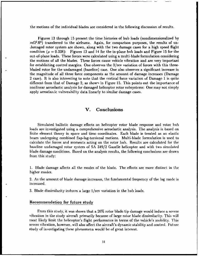
Figures 13 through 15 present the time histories of hub loads (nondimensionalized bymrW 2R2 ) transferred to the airframe. Again, for comparison purposes, the results of un-damaged rotor system are shown, along with the two damage cases for a high speed flightcondition (p = 0.338): Figures 13 and 14 for the in-plane hub loads and Figure 15 for theout-of-plane loads. These forces were calculated using a multi-blade formulation consideringthe motions of all the blades. These forces cause vehicle vibration and are very importantfor establishing control margins. One observes the 3/rev variation of forces with this three-bladed rotor for the undamaged (baseline) case. One also observes a significant increase inthe magnitude of all three force components as the amount of damage increases (Damage2 case). It is also interesting to note that the vertical force variation of Damage 1 is quitedifferent from that of Damage 2, as shown in Figure 15. This points out the importance ofnonlinear aeroelastic analysis for damaged helicopter rotor subsystems: One may not simplyapply aeroelastic vulnerability data linearly to similar damage cases.
V. Conclusions
Simulated ballistic damage effects on helicopter rotor blade response and rotor hubloads are investigated using a comprehensive aeroelastic analysis. The analysis is based onfinite element theory in space and time coordinates. Each blade is treated as an elasticbeam undergoing combined flap-lag-torsional motions. Multi-blade formulation is used tocalculate the forces and moments acting on the rotor hub. Results are calculated for thebaseline undamaged rotor system of SA 349/2 Gazelle helicopter and with two simulatedblade damage conditions. Based on the analysis results, the following conclusions are drawnfrom this study:
1. Blade damage affects all the modes of the blade. The effects are more distinct in thehigher modes.
2. As the amount of blade damage increases, the fundamental frequency of the lag mode isincreased.
3. Blade dissimilarity induces a large 1/rev variation in the hub loads.
Recommendation for future study
From this study, it was shown that a 20% rotor blade tip damage would induce a severevibration in the study aircraft primarily because of large rotor blade dissimilarity. This willmost likely limit the helicopter's flight performance in terms of the vehicle's mobility. Thissevere vibration, however, will also affect the aircraft's dynamic stability and control. Futurestudy of investigating these phenomena would be of great interest.
11
U1 Xi U2
Vi V2
W~ W2
wei U3 03 U4 W'2A '
I II S
Figure 1: Finite Element Model of a Helicopter Rotor Blade.
12
HUUB P LNE
w
al13
ov my.,
OF
HUB hLN
Wc
Fiue2 ce aico oo-eil Diar m
OF3
IICI .. ....
900
Present Analysis -0--800 - Flight Data (Gazelle) -+--
700 -
600 -
500
ON 400 -
300
200
100 I I I I I0.1 0.15 0.2 0.25 0.3 0.35 0.4
ADVANCE RATIO
Figure 3: Correlation of SA349/2 Shaft Power.
4 1 1 1Present Analysis -0--
3.5 Flight Data (Gazelle) -4--
3
2.5
2+------------------------------------
a 1.5
0o 1
0.5
0 II I II
0.1 0.15 0.2 0.25 0.3 0.35 0.4ADVANCE RATIO
Figure 4: Correlation of Flap Response - Coning Angle ,6.
14
4 I 1
Present Analysis ---S3 - Flight Data (Gazelle) -+-
41 2.,I4
r-4
to 0
4j
-2I I I
0.1 0.15 0.2 0.25 0.3 0.35 0.4ADVANCE RATIO
Figure 5: Correlation of Flap Response - Lateral Disk Tilt .
2 1
Present Analysis 0--1 Flight Data (Gazelle)-4--S~1-
0
-,.4
• q -2
0-2
• ~-3-0
-4 III I I
0.1 0.15 0.2 0.25 0.3 0.35 0.4ADVANCE RATIO
Figure 6: Correlation of Flap Response - Longitudinal Disk Tilt /1c'
15
10 % Damage Case
a) Damage 1
20 % Damage Case
b) Damage 2
Figure 7: Schematic of Blade Damage Cases.
16

Rotating Blade Mode Shapes: First Flap0.4 - 1
0.35 Undamaged -
Damage 1----0.3 Damage 2 ----- -
a)e
0 0.250.o-
V 0.2
- 0.154.4
0.1
0.05
0
-0.05
-0.1 __I
0 0.2 0.4 0.6 0.8Blade Radial Station, x/R
Figure 8: First Flap Mode Shapes of Undamaged and Damaged Blades.
Rotating Blade Mode Shapes: Second Flap0.3 1 1 1
Undamaged -S0.2 Damage 10. Damage 2 ----- -
o 0.1
S-0.1
6.4
4.4
S-0.2
-0.3 i I I
0 0.2 0.4 0.6 0.8 1Blade Radial Station, x/R
Figure 9: Second Flap Mode Shapes of Undamaged and Damaged Blades.
17
Rotating Blade Mode Shapes: First Lag0.4 1
0.35 UndamagedDamage 1
> 0.3 Damage 2
0 0.250.944j 0.2
44 0.15S0.1
0.05
S0 -0
-0.05 -
-0.1 I I I I
0 0.2 0.4 0.6 0.8Blade Radial Station, x/R
Figure 10: First Lag Mode Shapes of Undamaged and Damaged Blades.
Rotating Blade Mode Shapes: Second Lag0.3 1
Undamaged -
Damage 1 ----S0.2 Damage 2
022
o 0.14j
.4),4 0
) -0.1
-,-I
'4.
0 -0.2
o -0.2U
-0.3 I I I I
0 0.2 0.4 0.6 0.8Blade Radial Station, x/R
Figure 11: Second Lag Mode Shapes of Undamaged and Damaged Blades.
18
Rotating Blade Mode Shapes: First Torsion0.6 - I -
1 Undamaged -
S0.5 Damage 1Damage 2
0.40
•4
U 0.2,-4
0.10
0 0.. . . . ...
00.2 0.4 0.6 0.8Blade Radial Station, x/R
Figure 12: Torsional Mode Shapes of Undamaged and Damaged Blades.
0.2 1S~~Baseline -
S0.15 Damage 1 •-
0
o Damage 2 -El- --0.1 . I I
•- 00.0.0.08
BaeRda t•i E n _0.05
-0.05
0
-0.
1 -0.15 .. '
-0.2 JI I
0 50 100 150 200 250 300 350Azimuth Angle (deg)
Figure 13: Variations of Longitudinal In-Plane Hub Loads (p = 0.338).
19
0.2Baseline ---
0.15 Damage 1 -'--Damage 2 -El--
o 0.1 -LEI.
0.05 -"
S-0 1 ,, .'
0 A'$4J
S-0.05 -- Z
-0.2 I I I I I I
0 50 100 150 200 250 300 350Azimuth Angle (deg)
Figure 14: Variations of Lateral In-Plane Hub Loads (p = 0.338).
0.25Baseline -0--
U)Damage 1 -+--S0.2 Damage 2 -D--
0
.0 0.15
0.1
$4.
> 0.05
04 0 El " •
-0.05
-0.05 I I I I III
0 50 100 150 200 250 300 350Azimuth Angle (deg)
Figure 15: Variations of Out-of-Plane Hub Loads (p = 0.338).
20
VI. References
[1] Bir, G., 1. Chopra, and K. C. Kim et al. "University of Maryland Advanced Rotor-craft Code (UMARC): Theory Manual." Technical Report 92-02, Aerospace EngineeringDepartment, University of Maryland, College Park, MD, May 1992.
[21 Leishman, J. G. "Aerodynamic Characteristics of a Helicopter Rotor Airfoil As Affectedby Simulated Ballistic Damage." Army Research Laboratory Contractor Report, ARL-CR-66, Aberdeen Proving Ground, MD, September 1993.
[31 Johnson, W. "A Comprehensive Analytical Model of Rotorcraft Aerodynamic and Dy-namics." NASA Technical Memorandum (TM) No. 81182, NASA Ames, CA, June 1980.
[4] Panda, B. and I. Chopra. "Dynamics of Composite Rotor Blades in Forward Flight."Vertica, vol. 11, no. 1, January 1987.
[5] Johnson, W. "Assessment of Aerodynamic and Dynamic Models in a ComprehensiveAnalysis for Rotorcraft." Computers and Mathematics with Applications, vol. 12A, no. 1,January 1986.
[61 Ileffernan, R. M. and M. Gaubert. "Structural and Aerodynamic Loads and Per-formance Measurements of an SA349/2 Helicopter with an Advanced Geometry Rotor."NASA Technical Memorandum (TM) No. 88370, NASA Ames, CA, November 1986.
[7J Chopra, 1. "Helicopter Dynamics and Aeroelasticity." Technical Notes, Center for Ro-torcraft Education and Research, Aerospace Engineering Department, University of Mary-land, College Park, MD, January 1991.
21

INTENTIONALLY LEFT BLANK.
22
Appendix A
UMARC Input Data Set
Flight Condition Inputs
Advance ratio, p.
Rotor speed ratio, Q/fQ. f:0 is a nominal rotor rpm.
Density ratio, p/p0 : p. is a standard sea-level air density.
Flight angle, eFP (rad).
Tip Mach number, Mlp.
Main Rotor Overall Configuration Inputs
Rotor type (articulated or hingeless or bearingless).
Number of blades, N&.
Solidity, a
Lock number, -y.
Rotor thrust ratio, CT/Gr.
Hub location (x,y,z) with respect to aircraft c.g.
Main Rotor Blade Configuration Inputs
Linear twist, 01w (rad): positive for leading edge up.
Precone, /p (rad): negative for droop.
Root cutout, Rroot.
Number of spatial beam elements, n.
Blade Element Structural Properties Inputs : required for each n elements.
Element length, li.
Chord length, c.
Element mass, in.
Chord-wise offset of tensile axis ahead of elastic axis, e,.
23
Chord-wise offset of aerodynamic center behind elastic axis, ed.
Chord-wise offset of blade center of mass ahead of elastic axis, e9 .
Axial stiffness, EA.
Section stiffness const&nts, EB1 , EB2.
Warping rigidity, ECI.
Section warping constant, EC2 .
Flap-wise bending stiffness, Ely.
Lag (Chord-wise) bending stiffness, Ely.
Torsional stiffness, GJ.
Radius of gyration of blade cross section, kA.
Blade cross-sectional mass radius Or gyration, k,,,.
Blade cross-sectional mass radius of gyration in flap direction, k,,,,.
Blade cross-sectional mass radius of gyration in lag direction, k,,.
Blade sweep angle, 0,., (rad): negative for swept back.
Blade droop angle, Od, (rad): negative for droop down.
Tail Rotor Configuration Inputs
Tail rotor radius ratio, Rgr/R : R is a main rotor radius.
Tail rotor gear ratio, Qj,/Q : fQ is a main rotor rpm.
Tail rotor blade twist, 01,O (rad): positive for leading edge up.
Number of blades, N-,.
Solidity, art.
Tail rotor hub location (x,y,z) with respect to aircraft c.g.
Mean lift curve slope, Ci,,.
Mean chord length, ct.
Horizontal Tail Configuration Inputs
Horizontal tail area ratio, Sht/A: A is a main rotor disk area (ZR2).
Longitudinal distance between aircraft c.g. and tail aerodynamic center, zth.
Mean lift curve slope, c1i,.
24
Mean chord length, c?,.
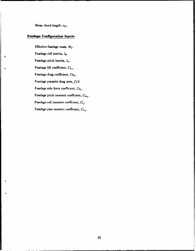
Fuselage Configuration Inputs
Effective fuselage mass, Mi.
Fuselage roll inertia, I#.
Fuselage pitch inertia, I.
Fuselage lift coefficient, CL,.
Fuselage drag coefficient, CD,.
Fuselage parasite drag area, f/A.
Fuselage side force coefficient, Cy,.
Fuselage pitch moment coefficient, C,,.
Fuselage roll moment coefficient, Cl-.
Fuselage yaw moment coefficient, C,,.
25
INTENTIONALLY LEFT BLANK.
26
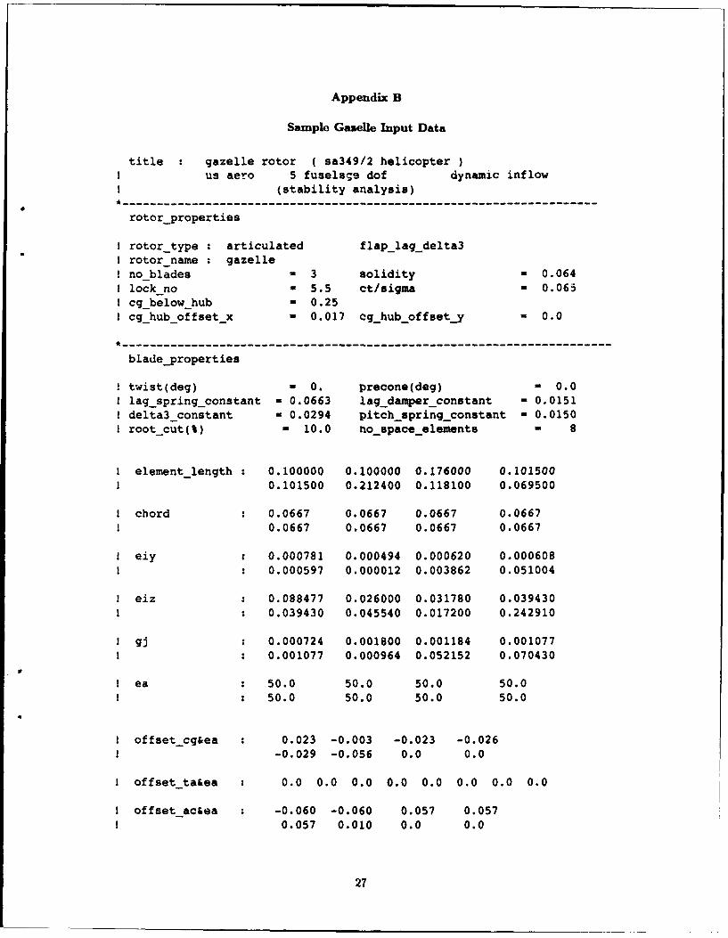
Appendix B
Sample Gazelle Input Data
title gazelle rotor ( sa349/2 helicopterI us aero 5 fuselage dof dynamic inflow
(stability analysis)*---------------------------------------------------------------------------------------------
rotor-properties
I rotortype : articulated flaplagdelta3i rotor name z gazelleI noblades W 3 solidity - 0.064! lockno = 5.5 ct/sigma M 0.065I cg below hub M 0.25I cghuboffsetx - 0.017 cg_huboffset.y a 0.0
*------------------------------------------------------------------------------------------------
bladeproperties
! twist(deg) 0 0. precone(deg) - 0.0I lag springconstant - 0.0663 lagjdamper constant - 0.01511 delta3_constant - 0.0294 pitchspringconstant - 0.0150I root_cut(%) - 10.0 no spaceelements - 8
1 element-length : 0.100000 0.100000 0.176000 0.101500I 0.101500 0.212400 0.118100 0.069500
i chord 0.0667 0.0667 0.0667 0.06670.0667 0.0667 0.0667 0.0667
eiy : 0.000781 0.000494 0.000620 0.0006080.000597 0.000012 0.003862 0.051004
1 eiz * 0.088477 0.026000 0.031780 0.0394301 0.039430 0.045540 0.017200 0.242910
gj a 0.000724 0.001800 0.001184 0.001077! 0.001077 0.000964 0.052152 0.070430
I ea 50.0 50.0 50.0 50.0e a 50.0 50.0 50.0 50.0
I offsetcg&ea 0.023 -0.003 -0.023 -0.0261 -0.029 -0.056 0.0 0.0
I offset ta&ea a 0.0 0.0 0.0 0.0 0.0 0.0 0.0 0.0
I offset ac&ea -0.060 -0.060 0.057 0.057! 0.057 0.010 0.0 0.0
27
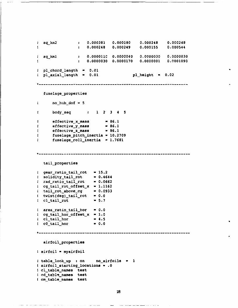
I sqkm2 0.000381 0.000180 0.000248 0.000248! 0.000248 0.000249 0.000155 0.000544
1 sq kml 0.000011C 0.0000040 0.0000030 0.0000030! 0.0000030 0.0000170 0.0000001 0.0001090
1 pl chord length - 0.01! pl_axiallength - 0.01 pl_height - 0.02
*-----------------------------------------------------------------------------------------
fuselageproperties
I no-hub-dof = 5
1 bodyseq 1 2 3 4 5
I effective_x_mass - 86.1! effective y_mass - 86.1
effective_z_mass - 86.1! fuselageypitch_inertia - 10.2709! fuselageroll_inertia - 1.7681
*------------------------------------------------------------------------------------------
tail_properties
I gearratio_tailrot - 15.21 soliditytail rot - 0.4644I radratiotail-rot 0.0662I cgtail_rot_offset_x - 1.1162I tailrotabovecg - 0.0933I twist(deg)_tail_rot - 0.0! cltailrot - 5.7
I arearatiotailhor - 0.0I cgtail_hor_offset_x - 1.0I clitailhor - 4.5
cO-tailhor - 0.0
*------------------------------------------------------------------------------------------
airfoilproperties
I airfoil - myairfoil
I table_lookup : on noairfoils 1I airfoilstartinglocations - .0! cltablenames testI cd_tablenames testI cm-tablenames test
28
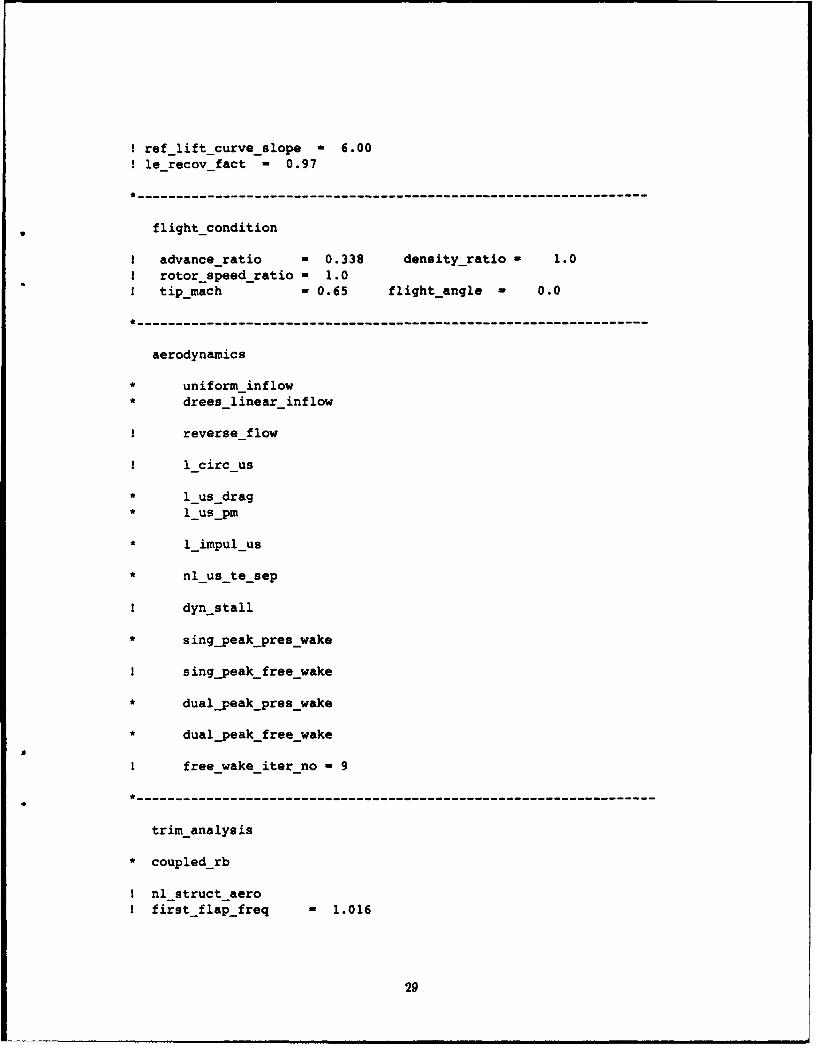
! reflift_curveslope - 6.001 lerecovfact - 0.97
--------------------------------------------------
flight_condition
I advanceratio - 0.338 densityratio - 1.0I rotorspeed ratio - 1.0I tip mach - 0.65 flightangle 0.0
--------------------------------------------------
aerodynamics
* uniform-inflow* dreeslinearinflow
! reverseflow
t lcirc-us
* 1us drag* lus pm
* limpul-us
* nlus te sep
I dynstall
* s ingpeak pres8wake
I singpeakfree wake
* dualypeakpreswake
* dualpeakfreewake
I free-wake-iter-no - 9
---------------------------------------------------
trim_analysis
* coupledrb
I nl-structaeroI firstflapfreq - 1.016
29
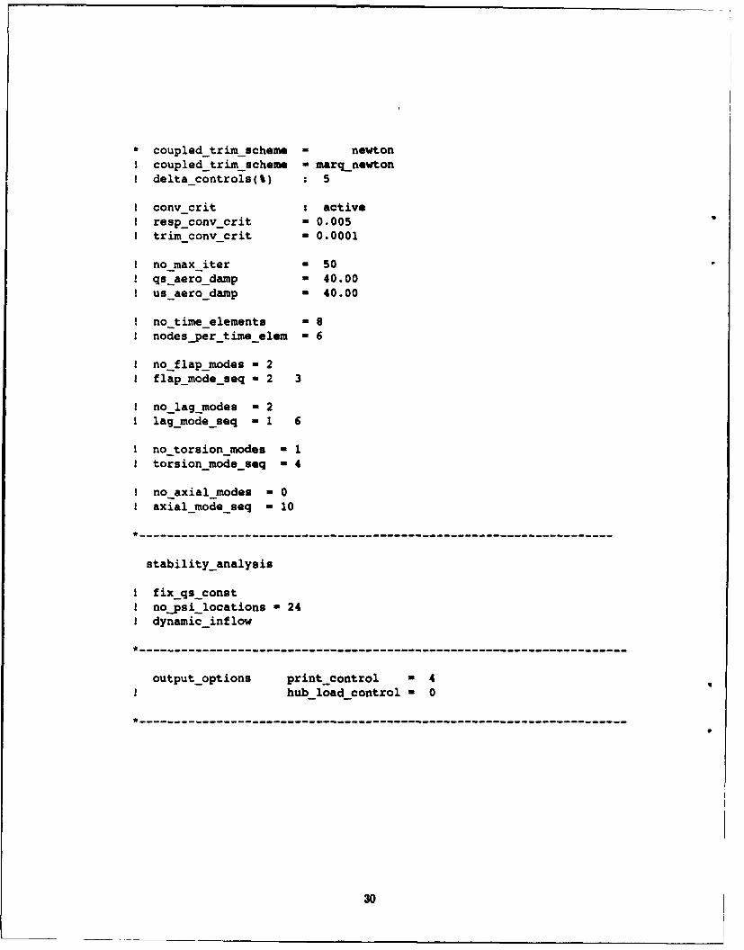
* coupled trimscheme - newtonI coupled trimscheme - marq_newtonI deltacontrols(%) : 5
1 cony crit : activeI resp_conv crit - 0.005I trim cony-crit - 0.0001
I no-max iter M 50! qs~aerodamp = 40.00! us aerodamp M 40.00
! no timeelements M 8! nodes_per time elem - 6
1 no flapmodes - 2I flapmodeseq 2 3
1 no lag modes - 21 lagmode_seq - 1 6
1 no torsion-modes - 1I torsionmode seq - 4
1 no axial-modes - 01 axialmode seq - 10
*--------------------------------------------------------------------------------------------
stabilityanalysis
I fixqs constI nojpsi locations - 241 dynamic_inflow
*-----------------------------------------------------------------------------------------------
output-options print-control = 4hub load control - 0
---------------------------------------------------------------------
30
No. of No. ofcopies Organization Copes Organization
2 Administrator I CommanderDefense Technical Info Center U.S. Army Missile CommandATIN: DTIC-DDA ATTN: AMSMI-RD-CS-R (DOC)Cameron Station Redstone Arsenal. AL 35898-5010Alexandria, VA 22304-6145
1 CommanderCommander U.S. Army Tank-Automotive CommandU.S. Army Materiel Command ATTN: AMSTA-JSK (Armor Eng. Br.)ATTN: AMCAM Warren, MI 48397-50005001 Eisenhower Ave.Alexandria, VA 22333-0001 1 Director
U.S. Army TRADOC Analysis CommandDirector ATTN: ATRC-WSRU.S. Army Research Laboratory White Sands Missile Range, NM 88002-5502ATTN: AMSRL-OP-CI-AD,
Tech Publishing (P- only) 1 Commandant2800 Powder Mill Rd. U.S. Army Infantry SchoolAdelphi, MD 20783-1145 ATTN: ATSH-CD (Security Mgr.)
Fort Benning, GA 31905-5660DirectorU.S. Army Research Laboratory ("'CIN awy) I CommandantATTN: AMSRL-OP-CI-AD, U.S. Army Infantry School
Records Management ATTN: ATSH-WCB-O2800 Powder Mill Rd. Fort Benning, GA 31905-5000Adelphi, MD 20783-1145
1 WL/MNOI2 Commander Eglin AFB, FL 32542-5000
U.S. Army Armament Research,Development, and Engineering Center Aberdeen Proving Ground
ATTN: SMCAR-IMI-IPicatinny Arsenal, NJ 07806-5000 2 Dir, USAMSAA
ATTN: AMXSY-D2 Commander AMXSY-MP, H. Cohen
U.S. Army Armament Research,Development, and Engineering Center 1 Cdr, USATECOM
ATTN: SMCAR-TDC ATTN: AMSTE-TCPicatinny Arsenal, NJ 07806-5000
1 Dir, ERDECDirector ATFN: SCBRD-RTBenet Weapons LaboratoryU.S. Army Armament Research, I Cdr, CBDA
Development, and Engineering Center ATTN: AMSCB CIIATTN: SMCAR-CCB-TLWatervliet, NY 12189-4050 1 Dir, USARL
ATIN: AMSRL-SL-lDirectorU.S. Army Advanced Systems Research 10 Dir. USARL
and Analysis Office (ATCOM) ATTN: AMSRL-OP-CI-B (Tech Lib)ATTN: AMSAT-R-NR, M/S 219-1Ames Research CenterMoffett Field, CA 94035-1000
31
No.o( No.ofComies Oraizto Cg~i Ortnnt
3 Commander I Sikorsky AircraftU.S. Army Aviation Systems Command Mail Stop ZI01AATTN: AMSAV-ESC, G. Kovacs ATTN: G. Burblis
SFAE-AV-BH-T, R. Olson 6900 Main SiSFAE-AV-AAH-SA, D. Roby Stratford, CT 06601-1381
4300 Goodfellow Blvd.St. Louis, MO 63120-1796 Aberdeen Provinf Ground
2 Commalder 1 Dir, USAMSAAAATD ATTN: AMXSY-AD, C. Aiston
ATTN: AMSAT-R-TF, G. HufstetlerSAVRT-TY-ASV, H. Reddick 43 Dir, USARL
USAATCOM ATTN: AMSRL-SL-B (2 cps)
Fort Eustis, VA 23604-5577 (Bldg. 328)
Commander AMSRL-SL-BA (20 cps)
ASC (Bldg. 1065)ATITN: ASC/XRM, G. BennettAFSC Headquarters AMSRL-SL-BA, K. Kim (20 cps)
Wright-Patterson AFB, OH 45433-6503 (Bldg. 1065)
Commander AMSRL-SL-N, M. Miler
WRDC (Bldg. E3331)AflN: WL/FIVST, M. LentzAFSC HeadquartersWright-Patterson AFB, OH 45433-6553
CommanderATTN: ASC/XRYA, K. McArdleEglin AFB, FL 32542
2 CommanderDahlgren DivisionNaval Surface Warfare CenterAMTN: Code G-13,
T. WasmundD. Dickinson
Dahlgren, VA 22448
McDonnell Douglas Helicopter CompanyATTN: William Sims5000 E. McDowell Rd.Mesa, AZ 85205
Boeing Helicopters DivisionATTN: N. CaravasosP.O. Box 16858Philadelphia, PA 19142
32
USER EVALUATION SHEET/CHANGE OF ADDRESS
This Laboratory undertakes a continuing effort to improvc the quality of the reports it publishes. Yourcomments/answers to the items/qucstions below will aid us in our efforts.
1. ARL ReportNumber ARL-TR-235 Date of Report October 1993
2. Date Report Received
3. Does this report satisfy a need? (Comment on purpose, related project, or other area of interest for
which the report will be used.)
4. Specifically, how is the report being used? (Information source, design data, procedure, source of
ideas, etc.)
5. Has the information in this report led to any quantitative savings as far as man-hours or dollars saved,
operating costs avoidcd, or efficiencies achieved, ctc? If so, please elaborate.
6. General Comments. What do you think should be changed to improve future reports? (Indicatechanges to organization, technical content, format, etc.)
Organization
CURRENT NameADDRESS
Street or P.O. Box No.
City, State, Zip Code
7. If indicating a Change of Address or Address Correction, please provide the Current or Correct addressabove and the Old or Incorrect address below.
Organization
OLD NameADDRESS
Street or P.O. Box No.
City, State, Zip Code
(Remove this sheet, fold as indicated, tape closed, and mail.)(DO NOT STAPLE)
DEPARTMENT OF THE ARMYNO POSTACENECESSAslyIF &4AALEO
IN THE
OFFICIAL BUSINESS BUSINESS REPLY ML UNITED STATES
RRSTOSMW KW NoOO1, AG, MO
Postage will be paid by addtessee___
DirectorU.S. Army Research LaboratoryATTN: AMSRL-OP-CI-B (Tech Lib)Aberdeen Proving Ground, MD 21005-5066
- ---------- -- ------- --- ---