
Army Programs FY 2019 Annual Report
292
Director, Operational Test and Evaluation FY 2019 Annual Report December 20, 2019 This report satisfies the provisions of Title 10, United States Code, Section 139. The report summarizes the operational test and evaluation activities (including live fire testing activities) of the Department of Defense during the preceding fiscal year. Robert F. Behler Director
Transcript of Army Programs FY 2019 Annual Report

Ballistic Missile Defense Systems
Joint Test and Evaluation
Live Fire Test and Evaluation
Cybersecurity
Test and Evaluation Resources
Air Force Programs
Navy Programs
Army Programs
DOD Programs
DOT&E Activity and Oversight
www.dote.osd.milIndex
Center for Countermeasures
Director, Operational Test and Evaluation
FY 2019 Annual Report
December 20, 2019
This report satisfies the provisions of Title 10, United States Code, Section 139. The report summarizes the operational test and evaluation activities (including live fire testing activities) of the Department of Defense during the preceding fiscal year.
Robert F. Behler Director
DIREC
TOR
OPERATIONAL TEST & EVA
LUATION
DO
T&
E F
Y 2019 A
nn
ual R
eport
DIR
ECTO
R OPERATIONAL TEST & EVALUATIO
N


F Y 1 9 I N T R O D U C T I O N
FY 2019 Annual Report
Introduction i
The most powerful element of our national defense is the warfighter. Our highly skilled, intelligent, and inventive soldiers, sailors, airmen, and marines keep our Nation safe and strong. As I stated during my November 7, 2017, confirmation hearing, I know from personal experience that there are three imperatives in combat: believe in yourself, your fellow warriors, and your training; believe in your mission and commanders; and believe in your equipment and weapons. Operational and live fire test and evaluation (OT&E and LFT&E) allow warfighters to believe in their equipment, weapons, and training; we determine whether a system is combat-credible, operationally suitable, and survivable. For the last 2 years, as the Director of Operational Test and Evaluation (DOT&E), I have focused on meeting the 2018 National Defense Strategy (NDS) mandate for greater lethality and readiness. From the DOT&E perspective, this means having the right assessment tools, infrastructure, and expertise and sufficient financial and human resources. As the NDS notes, “We cannot expect success fighting tomorrow’s conflicts with yesterday’s weapons or equipment. To address the scope and pace of our competitors’ and adversaries’ ambitions and capabilities, we must invest in modernization of key capabilities through sustained, predictable budgets.” Cybersecurity, test and evaluation (T&E) that represent realistic operational conditions, and testing and training for space-based systems remain my greatest challenges. While the operational test community has instituted some improvements in these areas, we still have much to do. Equally important, we are seeking ways to improve efficacy and efficiency. As part of this effort, this year DOT&E will work with the developmental test community to chart a 5-year path to integrating operational testing with developmental testing. We also will continue to pursue complementary approaches to streamline T&E, when possible, while maintaining the comprehensiveness that helps to ensure warfighters receive the robust weapons, systems, and training they need to execute their missions and return safely. I will keep Congress informed as we craft the plan for the future of T&E. No change in policy or process will affect DOT&E’s unique position as the sole independent source of authoritative OT&E data and findings.
CYBERSECURITY T&E
Cybersecurity presents enormous challenges for the DOD. Software and networks drive the Department’s warfighting, training, and business capabilities. Almost every weapon in the warfighter’s arsenal is software-defined, and we are likelier to “improve” system lethality by installing new software than by modifying hardware. As always, accurate, trusted, timely information is the discriminator on the battlefield, but now all of it – data, voice, video – traverses a digital medium of some kind. This dependence on software and networks makes cybersecurity T&E absolutely essential: A system cannot be deemed combat-credible and survivable without understanding its cybersecurity posture. In response, DOT&E has improved the realism and relevance of cyber tests and assessments. DOT&E’s Cybersecurity Assessment Program works with Combatant Commands and the Services to address their areas of greatest operational interest and impact. DOT&E provides subject matter experts to help cyber teams grow their capabilities, especially replication of advanced threats. Additionally, DOT&E analysis of data collected from observed cyber-attacks is used to augment detection and better understand mission effects. DOT&E’s structured yet flexible approach to tailoring operational tests and assessments is providing relevant, valuable cyber information. We repeatedly have identified cybersecurity threats and vulnerabilities as a major reason for determining a system was not survivable. However, overall, the DOD’s ability to test and evaluate cybersecurity is not keeping pace with the extremely high volume of complex systems and the aggressiveness of adversary attacks. The DOD needs advanced cyber testing tools, as well as automation that alerts the warfighter of anomalous software behavior. Cybersecurity T&E must become more realistic, for instance testing a system’s resilience by evaluating the operator’s ability to fight through a cyber-attack and restore operational capability. For situations where a cybersecurity-induced failure would present physical danger to the operator or platform, the DOD must have a realistic modeling and simulation (M&S) environment that accurately replicates the effects of cybersecurity compromise and tests the operator’s tactics, techniques, and procedures (TTPs).We also need more efficient and effective methodologies for holistic T&E of large, complex platforms with many interdependent components and subsystems, such as the F-35 and CVN 78. Further, the supply chain cannot be exempt; its networks, tools, facilities, and software factories must undergo regular cybersecurity assessment and monitoring.

F Y 1 9 I N T R O D U C T I O N
ii Introduction
Most importantly, until automated anomalous software detection tools are developed, the DOD test community needs more personnel with deep cyber domain expertise. The competition for high-quality cyber testers is a national challenge and the DOD is losing out. To defend against the full spectrum of potential cyber threats, the DOD needs to begin a major initiative to harness the world-class cyber personnel resident in the U.S. academic and commercial sectors. Without substantial improvements in cybersecurity T&E, especially in the workforce, the DOD risks lowering overall force readiness and lethality.
T&E INNOVATION & IMPROVEMENT
Realism in T&EThe quality of OT&E and LFT&E depends substantially on the tools and infrastructure available. In particular, we cannot know a system’s operational performance – lethality, survivability, suitability to mission – without running it through environments and scenarios that mirror what it would encounter during real-world use. For a combat system, this means putting it in the operator’s hands, going against current and emerging threats, and pushing the system to its physical and cyber limits. In many cases, however, the DOD cannot meet these criteria; the threat is either not available in a realistic density or at all, or realistic field conditions and testing (open air, open water) aren’t feasible. Part of the solution to these limitations is high-fidelity, accredited emulation and M&S. Replicating threats and a system’s operational profile via a digital environment can provide the information necessary for an accurate performance assessment, and can feed development and evaluation of TTPs and mission planning. The DOD already is successfully applying these types of technology to one of its most complex programs, the F-35. In FY19, F-35s flew 12 open-air trials at the Nevada Test and Training Range versus an array of radar signal emulators (RSEs). A reprogrammable open-loop emitter, the RSE pits aircraft against a wide variety of real adversary radar and integrated air defense system signals, including large, surface-to-air missile target engagement and acquisition radars. Without the RSEs, open-air sorties would not adequately represent the threat scenarios needed to properly evaluate the F-35. Results from the RSE open-air trials are being used to verify, validate, and accredit a key – perhaps the DOD’s most critical – M&S system, the Joint Simulation Environment (JSE). Scheduled to go live in summer 2020, the JSE will enable scenario-based T&E against modern threats in realistic densities. Within an all-digital environment that mimics the real world, warfighters will interact in real time with virtual entities. Due to the inherent limitations of open-air testing, the JSE will be the only venue available, other than actual combat against peer adversaries, to adequately evaluate the F-35. In addition to accuracy, M&S can increase T&E efficiency. For example, the Environment-Centric Weapons Analysis Facility (ECWAF), a real-time undersea warfare environment simulation with the MK 48 torpedo as hardware-in-the-loop, potentially will allow the Navy to eliminate up to 50 percent of in-water live firings for that munition. Live T&E always draws significant resources – time, money, personnel, and materiel. Replacing even a fraction of live runs will conserve resources while still helping to ensure that the warfighter receives the capability needed. Although M&S and emulation capabilities often are built with one particular program in mind, the acquisition and test communities must make sure these systems can grow to fit changing requirements and operational environments. To maximize our investment, M&S and emulators must be able to expand easily to accommodate additional platforms and new threats. Preparing for Emerging TechnologiesFor T&E to be realistic and accurate, T&E tools and processes must keep pace with emerging technologies. Thanks to a Congressional plus-up of $150 Million in the FY19 Defense Appropriations Act, the DOD is making significant progress in modernizing T&E infrastructure. With these funds, the Department will be able to augment its ability to collect hypersonic flight test data by adding telemetry and optics instrumentation to unmanned aerial systems, and will improve atmospheric measurement and end-game scoring and weapons effects. To assess directed-energy weapons, the DOD is pursuing development of high-power microwave diagnostics and high-energy laser instrumentation and target and scoring boards, as well as M&S tools to estimate directed-energy weapons’ damage effects and collateral effects. To improve and accelerate the evaluation piece of OT&E, particularly of next-generation aircraft, the DOD is upgrading its Big Data analytics capability. Additionally, DOT&E and the Test Resource Management Center (TRMC) have invested in autonomous cyber-threat emulation (Red Team tools), expanded cyber operational testing, and funded more research into artificial intelligence and machine-learning test methodologies. Space Testing and TrainingSpace is critical to the Nation’s security, economic prosperity, and scientific knowledge – and is now unquestionably a warfighting domain. The DOD intends to invest at least $100 Billion in space systems over the next decade, and we are not alone. We therefore must thoroughly understand how our systems will perform in space, particularly when facing manmade threats. Yet, the DOD

F Y 1 9 I N T R O D U C T I O N
Introduction iii
currently has no real means to assess adequately the operational effectiveness, suitability, and survivability of space-based systems in a representative environment. DOT&E, in conjunction with TRMC, is actively pursuing creation of such a capability. In keeping with the 2018 NDS commitment to “prioritize investments in resilience, reconstitution, and operations to assure our space capabilities,” this enduring infrastructure would enable T&E of current and future DOD space systems via a space warfighting combined test force, a “National Space Test and Training Range,” and ground-based space test facilities. The threat array would include cyber, directed-energy, kinetic and electronic-warfare threats, as well as natural hazards. This multi-layered space T&E capability is key to the DOD’s being able to demonstrate the true functionality, limitations, survivability, and employment considerations of space systems. It would enable validation of space-based warfighting TTPs, and development of multi-domain operating concepts. It also would provide more effective warfighter training, directly supporting the Secretary of Defense’s call for greater force readiness.
FRAMING TEST & EVALUATION TO SUPPORT THE NATIONAL DEFENSE STRATEGY
Middle Tier of Acquisition (MTA)DOT&E supports the MTA concept of faster acquisition and fielding in order to get capability to warfighters more quickly. Still, MTA programs must assess and demonstrate operational performance. Knowing whether a system is survivable and can fulfill the warfighter’s need is fundamental. Therefore, in accordance with the law, MTA programs remain subject to DOT&E oversight, including LFT&E, cybersecurity testing, and formal initial operational test and evaluation. The DOD is developing a new instruction that will require MTA strategies to include a test strategy; when an MTA program is selected for oversight, DOT&E will be the test strategy approval authority. An interim DOT&E policy, issued in October 2019, details expectations for testing, operational demonstrations, and reporting for MTA programs. For rapid prototyping initiatives, the test strategy should incorporate progressive operational and live-fire assessments of capabilities and limitations, based on data from incremental integrated test events during the prototype development program. For rapid fielding efforts, decisions should be based on integrated developmental and operational testing that demonstrates how the capability contributes to fulfilling the warfighter’s mission or a concept of operations. MTA operational demonstrations (ops demos) offer a unique opportunity to “fly before you buy” by involving the operational user before the initial production decision is made. DOT&E encourages tailoring MTA ops demos, and other OT&E, to enable rapid acquisition while maintaining acceptable risk to the warfighter. Advancing T&E Efficiency and EfficacyThe test community holds a critical role in providing operationally relevant and effective combat capability to the warfighter. To ensure that we fulfill this mission and the NDS mandate to deliver more lethal and more resilient capabilities at the “speed of relevance,” the operational test community is focusing on six principles. Three of these principles emphasize collaborative involvement of the operational and live fire test communities throughout the entire acquisition life cycle. First, OT teams and actual operators must be engaged in a program from its very inception, helping to shape requirements definition, budgeting, contracting, and engineering. Applying the operational perspective at the earliest stages will generate the soundest overall program plan with the greatest likelihood for success. OT involvement must then shift to continuous, timely feedback to the program manager and all other stakeholders. OT will not be limited to a “final exam” or formal reports at fixed milestones; instead, to keep pace with today’s rapid acquisition objectives, data collection and dissemination will be frequent and iterative. To get the best, most relevant information, the DOD must implement the third principle in this group: integrate and combine data collection and testing among the contractor, developmental, and operational test teams. These testing “silos” are artificial constructs. Rather, we should be open to utilizing any test event at any point in a program to provide the information any of these three communities may need. The remaining three principles collectively focus on tailoring testing to each program. Test teams will have the flexibility to adjust as needed in order to help field capability as rapidly as possible. This may include modifying and streamlining processes, products, and requirements in advance – or even after testing has commenced. We must be adaptive, taking advantage of what we learn during the testing process. As an example, in FY19 DOT&E approved elimination of 29 F-35 test missions (more than 200 sorties) because enough data had already been collected or the test outcome was obvious. Implementing these principles will produce actionable information earlier in, and regularly throughout, the acquisition process. By doing so, we will be able to mitigate program risk, enable sound decisions by the acquisition community, and give the commander and the warfighter a full understanding of what capability they have and how best to use it.

F Y 1 9 I N T R O D U C T I O N
iv Introduction
CONCLUSION
As I enter my third year in this position, I remain honored and proud to serve with the operational and live fire test and evaluation community to support our warfighters. We provide the unvarnished truth to the Congress and DOD leaders so that our lawmakers and the Department can ensure that those who put their lives on the line for the Nation have what they need. In keeping with operational security practices, this report does not contain certain details regarding system performance. As always, my staff and I stand ready to answer questions and to provide more information to members of Congress and their staff in the appropriate setting. I look forward to working with the dedicated women and men of the House and Senate in 2020.
Robert F. BehlerDirector

F Y 1 9 T A B L E O F C O N T E N T S
Table of Contents v
F Y 1 9 T A B L E O F C O N T E N T S
ContentsDOT&E Activity and OversightFY19 Activity Summary 1Program Oversight 7
DOD ProgramsDefense Agencies Initiative (DAI) 11DOD Healthcare Management System Modernization (DHMSM) 15F-35 Joint Strike Fighter (JSF) 19Global Command and Control System – Joint (GCCS-J) 33Joint Information Environment (JIE) 37Joint Regional Security Stack (JRSS) 41Key Management Infrastructure (KMI) 45Public Key Infrastructure (PKI) Increment 2 47International Test and Evaluation (IT&E) 49
Army ProgramsArmy Network Modernization 51Abrams M1A2 System Enhancement Program (SEP) Main Battle Tank (MBT) 53Active Protection Systems (APS) Program 55AH-64E Apache 57Armored Multi-Purpose Vehicle (AMPV) 59Army Integrated Air & Missile Defense (AIAMD) 63Army Tactical Wheeled Vehicles 65Bradley Family of Vehicles (BFoV) Engineering Change Proposal (ECP) 69Chemical Demilitarization Program – Assembled Chemical Weapons Alternatives (ACWA) 71Command Post Computing Environment (CPCE) 73Common Infrared Countermeasures (CIRCM) System 75Distributed Common Ground System – Army (DCGS-A) 77Electronic Warfare Planning and Management Tool (EWPMT) 79Integrated Personnel and Pay System – Army (IPPS-A) Increment II, Release 2 83Integrated Visual Augmentation System (IVAS) 85Joint Air-to-Ground Missile (JAGM) 87Joint Assault Bridge (JAB) 89Joint Light Tactical Vehicle (JLTV) 91M109A7 Family of Vehicles (FoV) Paladin Integrated Management (PIM) 93Mounted Computing Environment (MCE) 95Patriot Advanced Capability-3 (PAC-3) 97Soldier Protection System (SPS) 99Spider Increment 1A M7E1 Network Command Munition 101Stinger Proximity Fuze 103Stryker Family of Vehicles (FoV) 105UH-60V BLACK HAWK 107XM1158 7.62-mm Cartridge 109
F Y 1 9 T A B L E O F C O N T E N T S
vi Table of Contents
F Y 1 9 T A B L E O F C O N T E N T S
Navy ProgramsAegis Modernization Program 111Amphibious Combat Vehicle (ACV) Family of Vehicles 113CH-53K – Heavy Lift Replacement Program 115Columbia-Class Submarine 119Cooperative Engagement Capability (CEC) 121CVN 78 Gerald R. Ford-Class Nuclear Aircraft Carrier 123Distributed Aperture Infrared Countermeasure System (DAIRCM) 127Distributed Common Ground System – Navy (DCGS-N) Fleet Capability Release (FCR) 1 129E-2D Advanced Hawkeye 131F/A-18E/F Super Hornet 133Ground/Air Task Oriented Radar (G/ATOR) 135Joint Precision Approach and Landing System (JPALS) 137Littoral Combat Ship (LCS) 139MK 48 Torpedo Modifications 143MK 54 Lightweight Torpedo and Upgrades including: High Altitude Anti-Submarine Warfare (ASW) Weapon Capability (HAAWC) 145Mobile User Objective System (MUOS) 147MQ-4C Triton Unmanned Aircraft System 149MQ-8 Fire Scout 151Multi-Functional Information Distribution System (MIDS) Joint Tactical Radio System (JTRS) 153Offensive Anti-Surface Warfare (OASuW) Increment 1 155Over-the-Horizon Weapon System (OTH-WS) 157Ship Self Defense for DDG 1000 159SSN 774 Virginia-Class Submarine 161Standard Missile-6 (SM-6) 163Surface Mine Countermeasures Unmanned Undersea Vehicle (SMCM UUV) (also called Knifefish UUV) 165VH-92A Presidential Helicopter Replacement Program 167
Air Force ProgramsAIM-120 Advanced Medium-Range Air-to-Air Missile (AMRAAM) 171Air Operations Center – Weapon System (AOC-WS) 173B-52 Commercial Engine Replacement Program (CERP) 175B61 Mod 12 Life Extension Program Tail Kit Assesmbly 177C-130J 179Combat Rescue Helicopter (CRH) 181Enhanced Polar System (EPS) 183F-22A - RAPTOR Modernization 185Family of Advanced Beyond Line-of-Sight Terminals (FAB-T) 187Global Positioning System (GPS) Enterprise 189KC-46A 193RQ-4B Global Hawk High-Altitude Long-Endurance Unmanned Aerial System (UAS) 195Small Diameter Bomb (SDB) II 197Space Fence (SF) 201Space-Based Infrared System Program (SBIRS) 203

F Y 1 9 T A B L E O F C O N T E N T S
Table of Contents vii
F Y 1 9 T A B L E O F C O N T E N T S
Ballistic Missile Defense ProgramsBallistic Missile Defense System (BMDS) 205Sensors / Command and Control Architecture 209Ground-Based Midcourse Defense (GMD) 213Aegis Ballistic Missile Defense (Aegis BMD) 215Terminal High-Altitude Area Defense (THAAD) 219
Live Fire Test and Evaluation (LFT&E) 221
Cyber Assessments 227
Test and Evaluation Resources 235
Joint Test and Evaluation (JT&E) 241
The Center for Countermeasures (CCM) 247

F Y 1 9 T A B L E O F C O N T E N T S
viii
F Y 1 9 T A B L E O F C O N T E N T S

DOT&E Activityand Oversight

DOT&
E Ac
tivity
and
Over
sight
F Y 1 9 D O T & E A C T I V I T Y A N D O V E R S I G H T
Activity 1
Global Command and Control System – Joint (GCCS-J) TEMP Update
Joint Light Tactical Vehicle (JLTV) TEMP Update, Annex E*
Joint Precision Approach and Landing System (JPALS) Milestone C Revision D TEMP
Lower Tier Air and Missile Defense Sensor (LTAMDS) Program Urgent Materiel Release (UMR) TEMP
M109A7 Family of Vehicles Self-Propelled Howitzer and Carrier, Ammunition, Tracked TEMP*
MK21A Reentry Vehicle TEMP*
Mobile Protected Firepower (MPF) TEMP*
Mobile User Objective System (MUOS) Operations and Support TEMP
Presidential Helicopter Replacement Program (VH-92A) Cyber Survivability Annex TEMP
Space-Based Infrared System (SBIRS) Enterprise TEMP (ETEMP) Addendum
Space Fence Increment 1 TEMP
Tomahawk Weapon System for Navigation and Communication Modernization Upgrades Approval Revision H TEMP
UH-60V Blackhawk Utility Helicopter Fleet Milestone C TEMP
Unmanned Influence Sweep System (UISS) TEMP
VC-25B TEMP*
Virginia (SSN 774) Class Submarine Revision H TEMP*
40 mm XM1176 High Explosive Dual Purpose – Air burst (HEDP-AB) Cartridge TEMP*
Abrams M1A2 System Enhancement Package Version 3 (SEPv3) TEMP*
Advanced Anti-Radiation Guided Missile Extended Range TEMP
Aerosol and Vapor Chemical Agent Detector (AVCAD) TEMP
Amphibious Combat Vehicle (ACV) 1.1 Milestone C Update TEMP*
Armored Multi-Purpose Vehicle (AMPV) Milestone C TEMP*
Army Integrated Air and Missile Defense (AIAMD) Milestone C TEMP
B61-12 Milestone C TEMP
Bradley A4 Engineering Change Proposal (ECP) (Mobility) Program for M2A4/M7A4 Corrosion Test Change TEMP Change Pages
Command Post Computing Environment (CPCE) TEMP
Common Remotely Operated Weapon Station – Javelin (CROWS-J) TEMP Annex
E-2D Advanced Hawkeye Delta System Software Configuration Three 1654 Revision E TEMP
F/A-18E/F System Configuration Set (SCS) H14 TEMP
F-15 Eagle Passive Active Warning Survivability System Acquisition Strategy Update for the Milestone C TEMP
F-22 Tactical Link 16 and Tactical Mandates Modification Programs Milestone B TEMP
Global Combat Support System – Army (GCSS-Army) Increment 2 TEMP
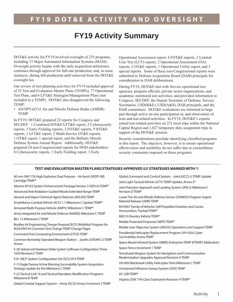
Operational Assessment report, 4 FOT&E reports, 2 Limited User Test (LUT) reports, 2 Operational Assessment (OA) reports, 2 OT&E reports, 1 Operational Utility report, and 3 special reports. Some of these non-Congressional reports were submitted to Defense Acquisition Board (DAB) principals for consideration in DAB deliberations.During FY19, DOT&E met with Service operational test agencies, program officials, private sector organizations, and academia; monitored test activities; and provided information to Congress, SECDEF, the Deputy Secretary of Defense, Service Secretaries, USD(R&E), USD(A&S), DAB principals, and the DAB committees. DOT&E evaluations are informed in large part through active on-site participation in, and observation of, tests and test-related activities. In FY19, DOT&E’s experts joined test-related activities on 231 local trips within the National Capital Region and 1,027 temporary duty assignment trips in support of the DOT&E mission.Security considerations preclude identifying classified programs in this report. The objective, however, is to ensure operational effectiveness and suitability do not suffer due to extraordinary security constraints imposed on those programs.
DOT&E activity for FY19 involved oversight of 235 programs, including 13 Major Automated Information Systems (MAIS). Oversight activity begins with the early acquisition milestones, continues through approval for full-rate production, and, in some instances, during full production until removed from the DOT&E oversight list.Our review of test planning activities for FY19 included approval of 32 Test and Evaluation Master Plans (TEMPs), 77 Operational Test Plans, and 6 LFT&E Strategies/Management Plans (not included in a TEMP). DOT&E also disapproved the following TEMP:• AN/SPY-6(V)1 Air and Missile Defense Radar (AMDR)
TEMPIn FY19, DOT&E prepared 23 reports for Congress and SECDEF: 1 Combined IOT&E/LFT&E report, 2 Cybersecurity reports, 3 Early Fielding reports, 2 FOT&E reports, 9 IOT&E reports, 1 LFT&E report, 2 Multi-Service OT&E reports, 1 OT&E report, 1 special report, and the Ballistic Missile Defense System Annual Report. Additionally, DOT&E prepared 24 non-Congressional reports for DOD stakeholders: 8 Cybersecurity reports, 1 Early Fielding report, 1 Early
FY19 Activity Summary
TEST AND EVALUATION MASTER PLANS/STRATEGIES APPROVED (LF STRATEGIES MARKED WITH *)

F Y 1 9 D O T & E A C T I V I T Y A N D O V E R S I G H T
2 Activity
Abrams M1A2 SEPv3 Cooperative Vulnerability and Penetration Assessment (CVPA) Test Plan
Abrams M1A2 System Enhancement Program v3 (SEPv3) FOT&E Operational Test Plan
Aegis Weapon System Advanced Capability Build-16 (ACB-16) IOT&E Cyber Survivability Test Plan (Baseline 9.2A2 Adversarial Assessment)
Air Intercept Missile 9X Block II FOT&E Test Plan
Air Intercept Missile 9X Block II, Air Intercept Missile 120C-7, and Air Intercept Missile 120D Cyber Survivability Test Plan
Amphibious Combat Vehicle 1.1 Cold Weather Test Plan
Amphibious Combat Vehicle Automatic Fire Extinguishing System Testing for the Production and Deployment Phase Detailed Test Plan
Amphibious Combat Vehicle Full-Up System-Level Detailed Test Plan
AN/AAQ-45 Distributed Aperture Infrared Countermeasures Quick Reaction Assessment Test Plan
AN/AAQ-45 Distributed Aperture Infrared Countermeasures Quick Reaction Assessment Test Plan for the AH-1Z and UH-1Y Platforms
AN/SQQ-89A(V)15 Advanced Capability Build (ACB 13) FOT&E Test Plan
Apache AH-64E Follow-on Operational Test 2 and the Joint Air-to-Ground Missile (JAGM) Initial Operational Test Operational Test Plan
Armored Multi-Purpose Vehicle System (AMPV) Live Fire System-Level Phase II Test Plan
B-21 Program Live Fire Alternate Test Plan
B61-12 Tail Kit Assembly IOT&E Plan
Ballistic Missile Defense System (BMDS) Flight Test Integrated-03 (FTI-03) Test Plan
Ballistic Missile Defense System (BMDS) Integrated Master Test Plan (IMTP) version 20.1
Ballistic Missile Defense System (BMDS) Integrated Master Test Plan (IMTP) version 21.0 Revision 8
Ballistic Missile Defense System (BMDS) Flight Test, Ground-Based Interceptor-11 Test Plan
Bradley A4 Engineering Change Proposal (Mobility) Automatic Fire Extinguishing System Test Operational Test Agency Test Plan
BYG-1 Combat Control System and BQQ-10 Sonar System for Acoustic Rapid Commercial Off-the-Shelf Insertion (A-RCI) (AN/BQQ-10) Advanced Processing Build (APB-15) Cyber Survivability Test Plan
C-130J Block Upgrade 8.1 Adversarial Assessment Test Plan
Command Post Computing Environment (CPCE) Version 3 Initial Operational Test Operational Test Plan
Common Infrared Countermeasure and the Limited Interim Missile (CIRCM) Warning System Free Flight Missile Test Detailed Test Plan
Common Infrared Countermeasure System Cybersecurity Cooperation Vulnerability and Penetration Assessment Test Plan
Common Infrared Countermeasure System Initial Operational Test Plan
Cooperative Engagement Capability (CEC) FOT&E Test Plan
Defense Agencies Initiative (DAI) Increment 3 Release 1 Operational Assessment Test Plan
Defense Agencies Initiative Increment 3 Release 1 Cyber Survivability Annex Operational Assessment (OA) Test Plan
OPERATIONAL TEST PLANS APPROVED
Distributed Common Ground System – Army (DCGS-A) Capability Drop 1 (CD 1) Limited User Test (LUT) Phase 2 Operational Test Agency Test Plan
E-2D Advanced Hawkeye Delta System Software Configuration Three FOT&E Plan
Electronic Warfare Planning and Management Tool (EWPMT) Cooperative Vulnerability and Penetration Assessment (CVPA) Plan
F/A-18E/F Infrared Search and Track (IRST) Block I AV6+ Configuration Test Plan
F-35 IOT&E Test Plan Approval of Changes
Family of Beyond Line-of-Site Terminals (FAB-T) and IOT&E Test Plan
Family of Beyond Line-of-Site Terminals (FAB-T) CVPA Test Plan
Family of Medium Tactical Vehicles A2 Full-Up System-Level Live Fire Test Design Plan
Ground/Air Task Oriented Radar Block 2 (GB2) Operational Test Plan
Integrated Personnel and Pay System – Army (IPPS-A) Increment II Release 2 Limited User Test 2 (LUT2) Test Plan
Joint Assault Bridge (JAB) Cooperative Vulnerability and Penetration Assessment (CVPA) Test Plan
Joint Assault Bridge (JAB) Initial Operational Test Operational Test Plan
Joint Assault Bridge (JAB) Initial Operational Test Operational Test Plan Revision
Joint Light Tactical Vehicle (JLTV) Operational Test Plan, Revision 1
Joint Regional Security Stack Version 1.5 Operational Assessment Plan
KC-46A IOT&E Test Plan
Light Attack Aircraft (LAA) Live Fire Alternative Test Plan
MC-8C Fire Scout Unmanned Aircraft System (UAS) Endurance Baseline Change Transmittal 1 to IOT&E for TEIN 1593
Military Health System (MHS) GENESIS FOT&E Cyber Survivability Test Plan Annex
MK 48 Mod 7 Common Broadband Advanced Sonar System (CBASS) Advanced Processor Build (APB) 5 Heavy Weight Torpedo (HWT) and MK 54 Mod 1 Light Weight Torpedo (LWT) Cyber Survivability Test Plan
Mobile User Objective System (MUOS) Multi-Service Operational Test and Evaluation (MOT&E) Test Plan
Mobile User Objective System (MUOS) Operational Test Agency (OTA) Cyber Survivability Test Plan
Mounted Computing Environment Customer Test (MCE CT) Operational Test Plan
Multi-functional Information Distribution System (MIDS) Joint Tactical Radio System (JTRS) Tactical Targeting Network Technology Operational Assessment Plan
Offensive Anti-Surface Warfare (OASuW) Increment 1 Long Range Anti-Ship Missile (LRASM) IOT&E Plan
Over-the-Horizon Weapon System (OTH WS) Quick Reaction Assessment (QRA) Test Plan
P-8A Advanced Airborne Sensor Cyber Test Plan
Patriot Post Deployment Build-8 Adversarial Assessment 2 Operational Test Plan
RQ-21A Blackjack FOT&E OT-D1 Test Plan

F Y 1 9 D O T & E A C T I V I T Y A N D O V E R S I G H T
Activity 3
Space-Based Infrared System (SBIRS) IOT&E Plan
Space Fence Increment 1 Cybersecurity Annex Test and Evaluation Plan
Space Fence Increment 1 Test Plan
Standard Missile-6 (SM-6) Block IA FOT&E Test Plan
Static Detonation Chamber at the Blue Grass Chemical Agent-Destruction Pilot Plant Combined Developmental Test and Evaluation Plan
Stryker Common Remotely Operated Weapon Station – Javelin (CROWS-J) Operational Assessment Test Plan
Surface Mine Countermeasures (SMCM) Unmanned Undersea Vehicle (UUV) (aka Knifefish) Operational Assessment (OT-B1) Test Plan, Revision 2
Surface Ship Undersea Warfare (USW) Combat System Program AN/SQQ-89A (V) 15 Advanced Capability Build 11 (ACB-11) Cyber Survivability Test Plan
TRIDENT II D5 Life Extension (LE) Commander Evaluation Test-2 (CET-2) OT&E Flight Test Support Plan
TRIDENT II D5 Life Extension (LE) Demonstration and Shakedown Operations-29 (DASO-29) OT&E Flight Test Support Plan
TRIDENT II D5 Strategic Weapons Systems (SWS) Test and Evaluation Plan Change 1
Trophy Active Protection System (APS) Operational Assessment Operational Test Plan
Trophy Active Protection System Phase II Ballistic Survivability Test and Evaluation for Urgent Materiel Release Operational Test Agency Test Plan
U.S. European Command (EUCOM) Exercise Austere Challenge 2019 Phase 2 (AC19-2) Capstone Event Plan
U.S. North American Aerospace Defense Command and U.S. Northern Command Vigilant Shield 2019 (VS19) Final Capstone Event Plan
UH-60V Cybersecurity Adversarial Assessment (AA) Test Plan
UH-60V Initial Operational Test Operational Test Plan
USS Abraham Lincoln Carrier Strike Group (ABESG) Composite Training Unit Exercise (C2X) Cybersecurity Assessment Plan
VH-92A Cyber Survivability Test Plan
LIVE FIRE TEST AND EVALUATION STRATEGIES/MANAGEMENT PLANS
B-21 Long Range Strike Bomber Alternate Live Fire Test Plan
Family of Medium Tactical Vehicles (FMTV) A1P2
Family of Medium Tactical Vehicles (FMTV) A2
Light Attack Aircraft Alternative Live Fire Test Plan
MDA Kinetic Kill Vehicle Live Fire Strategy
Trophy Active Protection System (APS) Operational Test Agency Test Plan for Phase II Ballistic Survivability

F Y 1 9 D O T & E A C T I V I T Y A N D O V E R S I G H T
4 Activity
TABLE 1. FY19 REPORTS TO CONGRESS
PROGRAM DATE
Combined Initial Operational Test and Evaluation and Live Fire Test and Evaluation Report
USS America (LHA 6) April 2019
Cybersecurity Report
Defensive Cyberspace Operations – Observations from Department of Defense Activities December 2018
Military Health System (MHS) GENESIS January 2019
Early Fielding Reports
Stryker Infantry Carrier Vehicle – Dragoon (ICV-D) November 2018
Stryker Common Remotely Operated Weapon Station – Javelin (CROWS-J) January 2019
Mod 7 Common Broadband Advanced Sonar System (CBASS) Torpedo Advanced Processor Build (APB) 5 September 2019
Follow-on Operational Test and Evaluation Reports
Stryker Double-V Hull A1 (DVH A1) Family of Vehicles (FoV) May 2019
Block III Variant of the Virginia-Class Submarine July 2019
Initial Operational Test and Evaluation Report
Military Health System (MHS) GENESIS November 2018
Advanced Capability Build 2011 (ACB-11) Version of the AN/SQQ-89A(V)15 Surface Ship Undersea Warfare Combat System December 2018
Integrated Strategic Planning and Analysis Network (ISPAN) Increment 4: Mission Planning and Analysis System (MPAS) January 2019
XM17/XM18 Modular Handgun System (MHS) January 2019
AN/TPS-80 Ground/Air Task Oriented Radar (G/ATOR) Block 1 and Block 2 May 2019
Coastal Battlefield Reconnaissance and Analysis (COBRA) Block 1 May 2019
Command Post Computing Environment (CPCE) June 2019
Spider Increment 1A M7E1 Network Command Munition August 2019
MQ-8C Fire Scout Unmanned Aircraft System (UAS) Endurance Baseline September 2019
Live Fire Test and Evaluation Reports
Javelin Spiral 2 Missile February 2019
Multi-Service Operational Test and Evaluation Reports
Joint Light Tactical Vehicle (JLTV) October 2018
Enhanced Polar System (EPS) September 2019
Operational Test and Evaluation Report
Aegis Weapon System (AWS) Advanced Capability Build 2012 (ACB-12) Baseline 9 and Cooperative Engagement Capability (CEC) June 2019
Special Report
Integrated Visual Augmentation System (IVAS) July 2019
Ballistic Missile Defense System Report
FY18 Assessment of the Ballistic Missile Defense System February 2019

F Y 1 9 D O T & E A C T I V I T Y A N D O V E R S I G H T
Activity 5
TABLE 2. OTHER FY19 REPORTS (NOT SENT TO CONGRESS)
PROGRAM DATE
Cybersecurity Reports
Defense Medical Information Exchange (DMIX) October 2018
Joint Operation Planning and Execution System October 2018
2018 Cybersecurity Assessment of U.S. Africa Command November 2018
Global Positioning System (GPS) Next Generation Operational Control System April 2019
Fiscal Year 2019 Navy Cybersecurity Assessment May 2019
2018 Cybersecurity Assessment of U.S. Indo-Pacific Command June 2019
U.S. European Command Cyber Readiness Campaign July 2019
Fiscal Year 2018-2019 Cybersecurity Assessment of U.S. Strategic Command August 2019
Early Fielding Report
Distributed Aperture Infrared Countermeasures (DAIRCM) System February 2019
Early Operational Assessment Report
Columbia-Class Submarine March 2019
Follow-On Operational Test and Evaluation Reports
Defense Agencies Initiative (DAI) Increment 2 November 2018
APR-39D(V)2 Radar Warning Receiver November 2018
MQ-1C Extended Range Gray Eagle Unmanned Aircraft System (UAS) January 2019
Key Management Infrastructure (KMI) Capability Increment 2 September 2019
Limited User Test Reports
UH-60V Milestone C December 2018
Armored Multi-Purpose Vehicle (AMPV) June 2019
Operational Assessment Reports
AN/TPS-80 Ground/Air Task Oriented Radar (G/ATOR) Block 2 November 2018
VH-92A Presidential Helicopter Replacement Program May 2019
Operational Test and Evaluation
Global Command and Control System – Joint (GCCS-J) May 2019
Distributed Common Ground System – Navy (DCGS-N) Increment 2 Fleet Capability Release 1 (FCR-1) August 2019
Operational Utility Evaluation Report
Joint Space Operations Center (JSpOC) Mission System (JMS) Increment 2 Service Pack 9 (SP-9) December 2018
Special Reports
Interim Assessment of Air Operations Center – Weapon System (AOC-WS) Increment 10.1 Release 10.1.15 October 2018
Air Operations Center – Weapon System (AOC-WS) Release 10.1 May 2019
Long Range Anti-Ship Missile (LRASM) on the F/A-18E/F September 2019

F Y 1 9 D O T & E A C T I V I T Y A N D O V E R S I G H T
6

F Y 1 9 D O T & E A C T I V I T Y A N D O V E R S I G H T
Oversight 7
Program Oversight
Per section 139, title 10, United States Code, DOT&E is the principal adviser to the Secretary of Defense and the Under Secretaries of Defense for Acquisition and Sustainment, and Research and Engineering. The Director is responsible for monitoring and reviewing all operational and live fire test and evaluation activities of the DOD. DOT&E selects a program for operational and/or live fire test and evaluation oversight if it meets one or more of the following criteria: • Program exceeds or has the potential to exceed the dollar
value threshold for a major program, to include Major Defense Acquisition Programs (MDAPs), designated major
subprograms, as well as highly classified programs and pre-MDAPs.
• Program has a high level of Congressional or DOD interest.• Weapons, equipment, or munitions that provide or enable
a critical mission warfighting capability or is a militarily significant change to a weapon system.
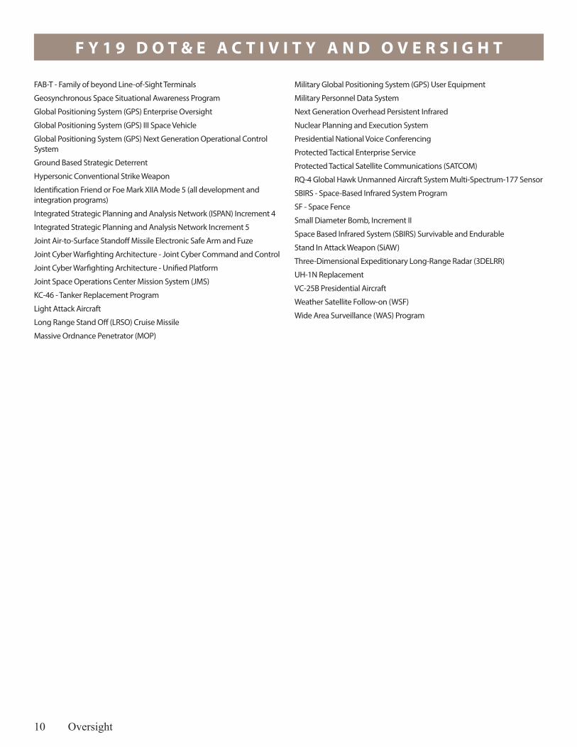
In FY19, using these criteria, DOT&E monitored 235 acquisition programs for operational test and evaluation and 86 acquisition programs for live fire test and evaluation.
DOD PROGRAMS
5th Generation Aerial Target
AC-130J High Energy Laser & Tactical Off-board Sensing
Air Transponders (Including the Automated Dependent Surveillance - Broadcast System)
BMDS - Ballistic Missile Defense System Program
CHEM DEMIL-ACWA - Chemical Demilitarization Program - Assembled Chemical Weapons Alternatives
Defense Agency Initiative (DAI)
Defense Enterprise Accounting and Management System - Increment 1 (DEAMS - Inc. 1)
Defense Medical Information Exchange (DMIX)
Defense Security Assistance Management System (DSAMS) - Block 3
DoD Healthcare Management System Modernization (DHMSM)
EDS - Explosive Destruction System
Global Command & Control System - Joint (GCCS-J)
Joint Aerial Layer Network
Joint Biological Tactical Detection System
Joint Information Environment
Joint Light Tactical Vehicle Family of Vehicles
Joint Operational Medicine Information Systems
Joint Regional Security Stack (JRSS)
Key Management Infrastructure (KMI)
Long-Range Discrimination Radar
milCloud
Mission Partner Environment - Information System
Public Key Infrastructure (PKI) Incr 2
SOCOM Dry Combat Submersible Medium (DCSM)
Teleport, Generation III
Theater Medical Information Program - Joint (TMIP-J) Block 2
ARMY PROGRAMS
120-mm Advanced Multi-Purpose (AMP), XM1147
3rd Generation Improved Forward Looking Infrared (3rd Gen FLIR)
Abrams M1A1 SA; M1A2 SEP; APS
Advanced Field Artillery Tactical Data System (AFATDS) Version 7
Advanced Threat Detection System
Aerosol and Vapor Chemical Agent Detector
AH-64E Apache Remanufacture/New Build
AN/TPQ-53 Radar System (Q-53)
Armored Multi-Purpose Vehicle (AMPV)
Armored Truck - Heavy Equipment Transporter (HET)
Army Contract Writing System
Army Integrated Air & Missile Defense (AIAMD)
Army Tactical Missile System - Modernization
Assured - Positioning, Navigation, & Timing (Assured - PNT)
Biometrics Enabling Capability (BEC) Increment 1
Biometrics Enabling Capability Increment 0
Black HAWK (UH-60M) - Utility Helicopter Program
Bradley ECP; MOD; APS
Cannon Delivered Area Effects Munitions (C-DAEM) Family of Munitions
CH-47F Block II Chinook
Command Post Computing Environment (CPCE)
Common Infrared Countermeasures (CIRCM)
Distributed Common Ground System - Army (DCGS-A)
Electronic Warfare Planning and Management Tool (EWPMT)
EXCALIBUR - Family of Precision, 155mm Projectiles
Extended Range Cannon Artillery (ERCA)

F Y 1 9 D O T & E A C T I V I T Y A N D O V E R S I G H T
8 Oversight
Family of Medium Tactical Vehicles A2 (FMTV A2)
Future Unmanned Aircraft System
Future Vertical Lift Family of Systems (FVL FoS)
Global Combat Support System Army (GCSS-A)
Ground Mobility Vehicle 1.1 (GMV 1.1)
Guided Multiple Launch Rocket System Family of Munitions Including Alternative Warhead (AW); Unitary; Extended Range (ER)
Handheld, Man pack, and Small Form Fit (including Handheld and Manpack components)
Heavy Dump Truck
HELLFIRE
High Mobility Artillery Rocket System (HIMARS)
Identification Friend or Foe Mark XIIA Mode 5 (all development and integration programs)
Improved High Explosive Dual Purpose 40mm Cartridge
Improved Turbine Engine Program (ITEP)
Indirect Fire Protection Capability Increment 2 - Intercept (IFPC Inc 2-I)
Integrated Personnel and Pay System - Army (IPPS-A) Increment 2
Integrated Visual Augmentation System (IVAS)
Javelin Antitank Missile System - Medium
Joint Air-to-Ground Missile (JAGM)
Joint Assault Bridge (JAB)
Joint Battle Command Platform (JBC-P)
Limited Interim Missile Warning System
Logistics Modernization Program (LMP)
Lower Tier Air and Missile Defense Sensor
M270A1 Multiple Launch Rocket System (MLRS)
M88A2 Heavy Equipment Recovery Combat Utility Lift Evacuation System (Hercules)
Maneuver-Short Range Air Defense
Mobile / Handheld Computing Environment (M/HCE)
Mobile Protected Firepower Increment 1 (MPF Inc 1)
Modular Handgun System (XM17/XM18)
Mounted Computing Environment (MCE)
Multi-Function Electronic Warfare (MFEW) Air Large
Near Real Time Identity Operations
Nett Warrior
Next Generation Combat Vehicle (NGCV) Optionally Manned Fighting Vehicle (OMFV)
Next Generation Squad Weapons (NGSW)
Paladin/FASSV Integrated Management (PIM)
PATRIOT PAC-3 - Patriot Advanced Capability 3
Precision Guidance Kit Family of Fuzes
Precision Strike Missile (PrSM)
RQ-7B SHADOW - Tactical Unmanned Aircraft System
Soldier Protection System
Spider XM7 Network Command Munition
Stryker Family of Vehicles to include all variants (including NBCRV)
Terrain Shaping Obstacles (TSO)
UH-60V Blackhawk
WIN-T INCREMENT 2 - Warfighter Information Network - Tactical Increment 2
XM1158 7.62mm Cartridge
NAVY PROGRAMS
Acoustic Rapid COTS Insertion for SONAR
Advanced Airborne Sensor
Advanced Arresting Gear
AEGIS Modernization (Baseline Upgrades)
AGM-88G Advanced Anti-Radiation Guided Missile Extended Range
AIM-9X - Air-to-Air Missile Upgrade Block II
Air and Missile Defense Radar (AMDR) / AN/SPY-6
Air Warfare Ship Self Defense Enterprise
Amphibious Combat Vehicle (ACV) Family of Vehicles (FoV)
AN/AQS-20X Minehunting Sonar and Tow Vehicle (all variants)
AN/SQQ-89A(V) Integrated USW Combat Systems Suite
Assault Breaching System Coastal Battlefield Reconnaissance and Analysis System (all variants)
Barracuda Mine Neutralization System
CANES - Consolidated Afloat Networks and Enterprise Services
Carrier Based Unmanned Air System
CH-53K - Heavy Lift Replacement Program
CMV-22 Joint Services Advanced Vertical Lift Aircraft - Osprey -- Carrier Onboard Delivery (COD)
Columbia-Class SSBN - including all supporting PARMs
Cooperative Engagement Capability (CEC)
CVN-78 – Gerald R. Ford-CLASS Nuclear Aircraft Carrier
DDG 1000 - Zumwalt-CLASS Destroyer and associated PARMs
DDG 51 Flight III and associated PARMS
Distributed Aperture Infrared Countermeasure (DAIRCM) System
Distributed Common Ground System - Navy (DCGS-N)
E-2D Advanced Hawkeye
Electro-Magnetic Aircraft Launching System
Enterprise Air Surveillance Radar
Evolved Sea Sparrow Missile Block 2
F/A-18E/F - SUPER HORNET Naval Strike Fighter
FFG(X) - Guided Missile Frigate
Future Pay and Personnel Management Solution (FPPS)
Ground/Air Task Oriented Radar (G/ATOR)

F Y 1 9 D O T & E A C T I V I T Y A N D O V E R S I G H T
Oversight 9
Identification Friend or Foe Mark XIIA Mode 5 (all development and integration programs)
Infrared Search and Track System
Joint Precision Approach and Landing System
LHA 6 Flt 0 and associated PARMs
LHA 6 Flt I and associated PARMs
Light Armored Vehicle
Littoral Combat Ship (LCS) Anti-submarine Warfare (ASW) Mission Package to include all associated vehicles, communications, sensors, weapon systems, support equipment, software, & support aircraft that are in development
Littoral Combat Ship (LCS) Mine-countermeasures (MCM) Mission Package to include all associated vehicles, communications, sensors, weapon systems, support equipment, software, and support aircraft that are in development
Littoral Combat Ship (LCS), FREEDOM and INDEPENDENCE Variant Seaframes
Littoral Combat Ship Surface Warfare (SUW) Mission Package to include all associated vehicles, communications, sensors, weapon systems, support equipment, software, & support aircraft in development, 30-mm, SSMM/Longbow HELLFIRE/ammunition lethality
LPD 17 Flt II
Mk 54 torpedo/MK - 54 VLA/MK 54 Upgrades Including High Altitude ASW Weapon Capability (HAAWC)
MK-48 CBASS Torpedo including all upgrades
Mobile User Objective System (MUOS)
MQ-4C Triton
MQ-8 Fire Scout Unmanned Aircraft System
Multi-Functional Information Distribution System (includes integration into USAF & USN aircraft)
Multi-static Active Coherent (MAC) System
MV-22 Joint Services Advanced Vertical Lift Aircraft - Osprey
Naval Integrated Fire Control - Counter Air (NIFC-CA) From the Air
Navy Expendable Airborne Electronic Attack (EA2)
Navy Multiband Terminal Program (NMT)
Next Generation Jammer - Increment 1 (Mid-Band)
Next Generation Jammer - Increment 2 (Low Band)
Next Generation Land Attack Weapon
Offensive Anti-Surface Warfare Increment 1 Long Range Anti-Ship Missile
Offensive Anti-Surface Warfare, Increment 2 (Air and Surface Launch)
Over The Horizon Weapon System
Rolling Airframe Missile Block 2 Program
RQ-21A Unmanned Aircraft System (UAS)
Ship Self Defense System (SSDS)
Ship to Shore Connector
Standard Missile 2 (SM-2) including all mods
Standard Missile-6 (SM-6)
Submarine Torpedo Defense System (Sub TDS) including Next Generation Countermeasure System (NGCM)
Surface Electronic Warfare Improvement Program Block 2
Surface Electronic Warfare Improvement Program Block 3
Surface Mine Countermeasures Unmanned Undersea Vehicle (also called Knifefish UUV) (SMCM UUV)
Tactical Tomahawk Modernization and Enhanced Tactical Tomahawk (Maritime Strike) (includes changes to planning and weapon control system)
T-AO 205 Oiler
TRIDENT II MISSILE - Sea Launched Ballistic Missile
Unmanned Influence Sweep System (UISS) include Unmanned Surface Vessel (USV) and Unmanned Surface Sweep System (US3)
USMC MRAP-Cougar
VH-92A Presidential Helicopter
Virginia-Class SSN (all variants)
AIR FORCE PROGRAMS
Advanced Pilot Trainer
AEHF - Advanced Extremely High Frequency (AEHF) Satellite Program
AIM-120 Advanced Medium-Range Air-to-Air Missile
Air Force Integrated Personnel and Pay System (AF-IPPS)
Air Force Maintenance, Repair and Overhaul Initiative (MROi)
Air Operations Center - Weapon System (AOC-WS)
Air-Launched Rapid Response Weapon
B-2 Defensive Management System Modernization (DMS-M)
B-21 Long Range Strike Bomber
B-52 Commercial Engine Replacement Program (CERP)
B-52 Radar Modernization Program (RMP)
B61 Mod 12 Life Extension Program Tail Kit Assembly
C-130J - HERCULES Cargo Aircraft Program
Combat Rescue Helicopter (CRH)
Command and Control Air Operations Suite (C2AOS)/Command and Control Information Services (C2IS) (Follow-on to Theater Battle Management Core System, new capabilities for AOC and joint software suites)
Deliberate and Crisis Action Planning and Execution Segments (DCAPES) Inc. 2B
Enterprise Space Battle Management Command & Control / Command and Control for Space System
EPS - Enhanced Polar System
Evolved Strategic Satellite Communications
F-15 Eagle Passive Active Warning Survivability System
F-15C Infrared Search and Track (IRST)
F-16 Radar Modernization Program
F-22 - RAPTOR Advanced Tactical Fighter
F-35 - Lightning II Joint Strike Fighter (JSF) Program
F Y 1 9 D O T & E A C T I V I T Y A N D O V E R S I G H T
10 Oversight
FAB-T - Family of beyond Line-of-Sight Terminals
Geosynchronous Space Situational Awareness Program
Global Positioning System (GPS) Enterprise Oversight
Global Positioning System (GPS) III Space Vehicle
Global Positioning System (GPS) Next Generation Operational Control System
Ground Based Strategic Deterrent
Hypersonic Conventional Strike Weapon
Identification Friend or Foe Mark XIIA Mode 5 (all development and integration programs)
Integrated Strategic Planning and Analysis Network (ISPAN) Increment 4
Integrated Strategic Planning and Analysis Network Increment 5
Joint Air-to-Surface Standoff Missile Electronic Safe Arm and Fuze
Joint Cyber Warfighting Architecture - Joint Cyber Command and Control
Joint Cyber Warfighting Architecture - Unified Platform
Joint Space Operations Center Mission System (JMS)
KC-46 - Tanker Replacement Program
Light Attack Aircraft
Long Range Stand Off (LRSO) Cruise Missile
Massive Ordnance Penetrator (MOP)
Military Global Positioning System (GPS) User Equipment
Military Personnel Data System
Next Generation Overhead Persistent Infrared
Nuclear Planning and Execution System
Presidential National Voice Conferencing
Protected Tactical Enterprise Service
Protected Tactical Satellite Communications (SATCOM)
RQ-4 Global Hawk Unmanned Aircraft System Multi-Spectrum-177 Sensor
SBIRS - Space-Based Infrared System Program
SF - Space Fence
Small Diameter Bomb, Increment II
Space Based Infrared System (SBIRS) Survivable and Endurable
Stand In Attack Weapon (SiAW)
Three-Dimensional Expeditionary Long-Range Radar (3DELRR)
UH-1N Replacement
VC-25B Presidential Aircraft
Weather Satellite Follow-on (WSF)
Wide Area Surveillance (WAS) Program

DOD Programs

DOD
Prog
ram
s

F Y 1 9 D O D P R O G R A M S
DAI 11
• DAI is operationally effective. The system successfully completed 100 percent of all critical tasks within 5 business process areas throughout all operational testing.
• DAI is operationally suitable. Overall system availability was high; however, usability ranged from marginal to not acceptable. - DAI exceeded system availability requirements with
99 percent system availability. - Help desk metrics indicate the DAI system is sustainable.
However, most Agencies provide additional funding to sustain Tier 1 (local) help desk support, functional
Executive Summary• The Joint Interoperability Test Command (JITC) conducted an
operational assessment (OA) of Defense Agencies Initiative (DAI) Increment 3 Release 1 from April 8 through May 31, 2019. - During the OA, JITC evaluated new and existing
capabilities implemented by DAI-equipped defense agencies, DOD field activities, and other defense organizations (collectively referred to here as Agencies).
- JITC also evaluated new functionality for Defense Information Systems Agency (DISA), an agency that recently migrated to using DAI.
Defense Agencies Initiative (DAI)

F Y 1 9 D O D P R O G R A M S
12 DAI
additional capabilities to existing Agencies and to add DISA, the Defense Commissary Agency, and potentially other Agencies from FY18 through FY23. DISA went live with Time and Labor capabilities in June 2018 as part of Increment 3 Release 0.1, and increased the DAI user base to 45,725 users at 1,834 locations worldwide.
- Increment 3 Release 1.0 was fielded in October 2018 and completed DISA’s migration to using DAI for General Funds Accounting.
• DAI supports financial management requirements in the Federal Financial Management Improvement Act and DOD Business Enterprise Architecture, and is a key tool for helping DOD Agencies have their financial statements validated as ready for audit.
MissionFinancial Managers in defense agencies use DAI to transform their budget, finance, and accounting operations to achieve accurate and reliable financial information in support of financial accountability and effective and efficient decision-making.
Major Contractors• CACI – Arlington, Virginia• International Business Machines – Armonk, New York• Northrop Grumman – Falls Church, Virginia• Amyx, Inc. – Reston, Virginia
and system training, and support for new capability development.
• Based on previous testing and the remediation of all but one open finding, DAI is survivable against a cyber threat having limited to moderate capabilities.
System• DAI is an integrated financial management solution that
provides a real-time, web-based system of integrated business processes used by defense financial managers, program managers, auditors, and the Defense Finance and Accounting Service. The DAI core functionality is based on commercially available enterprise resource planning solutions.
• DAI subsumes many systems and standardizes business processes for multiple DOD Agencies. It modernizes these business processes by streamlining management capabilities to address financial reporting material weaknesses, and support financial statement auditability.
• DISA provides facilities, network infrastructure, and the hardware operating system for DAI servers at DISA data centers.
• Agencies employ DAI worldwide and across a variety of operational environments via a web portal using each Agency’s existing information system infrastructure.
• The DAI program is delivering capability incrementally: - The DAI Program Management Office (PMO) has begun
development and fielding of Increment 3 to provide
Activity • On October 3, 2017, the USD(AT&L) issued a Full
Deployment Decision for DAI Increment 2 and a development Authority to Proceed for DAI Increment 3.
• On September 26, 2018, the USD(A&S) issued an Acquisition Decision Memorandum delegating Milestone Decision Authority to the Defense Logistics Agency (DLA) for DAI Increment 3 and all future program increments.
• The DAI PMO conducted three developmental test events of DAI Increment 3 Release 2 in FY19: - Development integration test from April 18 through
June 11, 2019- System integration test from June 24 through July 26, 2019- User acceptance test from August 12 through September
13, 2019• In coordination with DISA, the DAI PMO conducted its
annual Continuity of Operations (COOP) exercise from January 7 – 11, 2019.
• From April 8 through May 31, 2019, JITC conducted an OA of DAI Increment 3 Release 1 in accordance with a DOT&E-approved test plan. Interoperability Certification data were collected from November 2018 through May 2019, and JITC issued the Joint Interoperability Certification for DAI Increment 3 Release 1 on August 30, 2019.
• From January 14 – 29, 2019, JITC and the DISA Red Team conducted a Cooperative Vulnerability and Penetration
Assessment (CVPA) to verify that actions taken by the DAI PMO successfully corrected open findings from Increment 2 FOT&E.
• From May 13 – 17, 2019, JITC and the DISA Red Team conducted an Adversarial Assessment (AA) to determine the cyber survivability of the DAI.
• DOT&E published its DAI Increment 3 Release 1 OA report in November 2019.
Assessment • DAI is operationally effective and continues to provide
significant improvements compared to previous T&E events.- During the Increment 3 Release 1 OA, DAI successfully
completed 242 of 242 observed tasks (100 percent). • DAI is operationally suitable. Auditability, reliability,
availability, maintainability, and sustainability of the help desk support were all acceptable. However, System Usability Scale scores continue to show marginal to low acceptance of the system.- DAI exceeded system availability requirements with
99 percent system availability. DAI also exceeded the performance requirements for other reliability, availability, and maintainability measures during the OA.

F Y 1 9 D O D P R O G R A M S
DAI 13
- The DAI PMO has a goal of one 27-hour maintenance period completed during one weekend per month. Achieving that goal would better support worldwide operations and improve weekend operations during peak periods, especially during the critical closeout period near the end of the fiscal year.
- In spite of the improvements in the DAI system, users continue to give the program a marginal System Usability Scale score. Agency users with more experience scored DAI higher. Frequent user comments on DAI functionality related to system slowness and difficulty of entering data and generating DAI reports, queries, and search requests.
- The DAI concept of operations for help desk support places the Tier 1 (local) support burden on the using agency, with the DAI PMO only providing dedicated higher tier support. Most Agencies provide additional funding to obtain additional manning for local help desk support, training, and support for new capability development. This support concept masks the true cost of DAI sustainment for the DOD enterprise.
- The DAI Help Desk processed 7,509 service requests between November 1, 2018, and May 3, 2019, with the number of open tickets decreasing from 738 to 312 during that period.
• DAI is survivable against a cyber threat having limited to moderate capabilities.
- During the CVPA, JITC and the DISA Red Team verified that the DAI PMO had corrected all but one open finding from pervious testing.
- Net Defenders from Agencies using DAI successfully detected and reacted to the AA activities during Increment 3 Release 1 testing.
• Based on the results of FY19 COOP exercises and previous test events, DOT&E and JITC assessed the DAI COOP capability as meeting requirements. Although the PMO met established requirements for recovery of the system, their service provider (DISA) did not meet agreed upon Service-level agreements for some critical services.
Recommendations• The DAI PMO should:
1. Improve system performance to reduce response times, month-end report generation times, and unexpected errors.
2. Work with DISA to ensure it is prepared to meet Service-level agreements for recovery times.
3. In conjunction with JITC, measure system responsiveness during operational testing to quantify the latency problems identified through user survey responses during Increment 2 and 3 (Release 1) testing.
• The full list of recommendations is available in the November 2019 DOT&E DAI OA report.

14
F Y 1 9 D O D P R O G R A M S

F Y 1 9 D O D P R O G R A M S
DHMSM 15
• In FY19, the Program Executive Officer (PEO) Defense Healthcare Management System (DHMS) and the Program Office expended substantial resources and effort to improve the cybersecurity posture of MHS GENESIS and to hold the Leidos Partnership for Defense Health (LPDH) and Cerner accountable for satisfying DOD cybersecurity requirements. PEO DHMS and the Program Office collaborated closely with the Defense Health Agency (DHA), DOD Chief Information Officer (CIO), DOT&E, and JITC. During a Cooperative Vulnerability and Penetration Assessment (CVPA), JITC discovered 7 new vulnerabilities, and validated 9 of 20 previously identified vulnerabilities were resolved and 11 were still present in the system. Patient records are at risk because of the vendor's lack of progress in meeting DOD cybersecurity requirements.
System• The Program Office plans to field MHS GENESIS, a
modernized Electronic Health Records system, to 205,000
Executive Summary• The DOD Healthcare
Management System Modernization (DHMSM) Program Office is fielding Military Health System (MHS) GENESIS to transform the way the DOD and the Department of Veterans Affairs provide military and veteran healthcare missions by creating a single health care record for each patient, used by both agencies. Currently, health care records reside in multiple legacy systems, making it difficult for health care providers to understand a patient’s complete medical history. MHS GENESIS provides an integrated health record and delivers new capabilities to increase patient safety, such as barcode medication administration and decision support tools.
• MHS GENESIS will be deployed to DOD hospitals and clinics worldwide. MHS facilities encompass 54 hospitals, 377 medical clinics, and 270 dental clinics. Over 205,000 medical staff members will use the system to deliver and document healthcare for 9.4 million beneficiaries.
• In FY19, the Program Office developed and executed an MHS GENESIS corrective action plan to resolve the 388 incident reports identified during IOT&E. As of November 7, 2019, the Program Office had addressed 79 percent of these incident reports. The Joint Interoperability Test Command (JITC) will verify and validate Program Office fixes to IOT&E incident reports during an FOT&E planned for January and February 2020.
• The Program Office has improved MHS GENESIS training as compared to the Initial Operational Capability (IOC) site training. Trainers are now proficient at teaching operational scenarios and workflows, and users are fully engaged in the training. In preparation for FOT&E, MHS GENESIS deployed to four additional sites on September 7, 2019.
DOD Healthcare Management System Modernization (DHMSM)

F Y 1 9 D O D P R O G R A M S
16 DHMSM
software suite including AHLTA-Theater, TMIP CHCS Caché, and AHLTA-Mobile.
MissionDOD medical staff will use MHS GENESIS to manage delivery of en route care, dentistry, emergency department, immunization, laboratory, radiology, operating room, pharmacy, vision, audiology, and inpatient/outpatient services. DOD medical staff will also use MHS GENESIS to perform administrative support, front desk operations, logistics, billing, and business intelligence.
Major Contractors• Leidos – Reston, Virginia• Cerner – Kansas City, Missouri• Accenture Federal Services – Arlington, Virginia• Henry Schein, Inc. – Melville, New York
MHS personnel providing care for 9.4 million DOD beneficiaries worldwide. MHS facilities encompass 54 hospitals, 377 medical clinics, and 270 dental clinics.
• MHS GENESIS comprises three major elements: - The Millennium suite of applications, developed by
Cerner, which provides medical capabilities- Dentrix Enterprise, developed by Henry Schein, Inc.,
which provides dental capabilities- Orion Rhapsody Integration Engine, developed by
Orion Health, which enables the majority of the external information exchanges
• MHS GENESIS will replace legacy healthcare systems including the Armed Forces Health Longitudinal Technology Application (AHLTA), Composite Health Care System (CHCS), and Essentris inpatient system. MHS GENESIS will replace legacy Operational Medicine components of the Theater Medical Information Program (TMIP) – Joint
Activity • In FY19, the Program Office developed and executed an MHS
GENESIS corrective action plan to resolve IOT&E incident reports from the four IOC sites. JITC conducted IOT&E at the first three IOC sites from September through December 2017 and at the fourth IOC site in July 2018.
• DHA conducted a DOD CIO-directed Independent Verification and Validation of MHS GENESIS from November 29, 2018, to March 6, 2019.
• The Program Office-led Cybersecurity Integrated Working Group (CIWG) developed and executed an MHS GENESIS cybersecurity get-well plan from December 2018 to May 2019.
• The Program Office installed Millennium Upgrade Version 2018.01.03 on April 26, 2019.
• JITC, with Service Operational Test Agency (OTA) assistance, observed and evaluated MHS GENESIS training provided at the next wave of MHS GENESIS sites from May 12 to July 27, 2019.
• The Program Office conducted a Cybersecurity Table Top (CTT) exercise to improve the MHS GENESIS cybersecurity posture on May 21 – 23, 2019.
• The Program Office installed Dentrix Enterprise Upgrade Version 8.0.95.325 on June 15, 2019.
• The Program Office implemented MHS GENESIS enhancements in August and September 2019, including an Oncology solution, Oral Maxillofacial Surgery solution, Defense Medical Logistics Enterprise System interface, Bi-Directional Pharmacy interface, and Cardiovascular picture archiving and communication system interface.
• The Program Office deployed MHS GENESIS at David Grant Medical Center, Travis AFB, California; Naval Health Clinic Lemoore, Naval Air Station Lemoore, California; Presidio of Monterey Army Health Clinic, Monterey, California; and Mountain Home Clinic, Mountain Home AFB, Idaho, on September 7, 2019. These sites were designated “Wave Travis” sites.
• DOT&E and JITC, with Service OTA assistance, observed the Wave Travis Go-Live on September 9 – 27, 2019.
• JITC and the Network Information Warfare Center (NIWC) Red Team conducted a CVPA at the Cerner Technology Center from July 29 to August 9, 2019, and at Travis AFB in FY20. The CVPAs were conducted in accordance with a DOT&E-approved test plan.
Assessment • As of November 7, 2019, JITC closed 84 of 388 (22 percent)
incident reports and identified an additional 223 of 388 (57 percent) as pending validation of closure. Of the 57 top priority incident reports, JITC closed 7 of 57 (12 percent) and identified 41 of 57 (72 percent) as pending validation of closure. JITC will validate Program Office fixes to IOT&E incident reports during an FOT&E in January and February 2020.
• The CIWG reported that out of 28 tasks, 6 were closed, 19 were closed pending validation, and 3 were being monitored.
• The CTT identified 12 potential cybersecurity threat vectors and associated risks to help inform MHS GENESIS cybersecurity hardening efforts.
• The Program Office improved Wave Travis MHS GENESIS training as compared to the IOC site training. Trainers were highly proficient at teaching the scenarios and workflows, and users were fully engaged in the training and understood the training material before accessing the MHS GENESIS system.
• The Cerner Data Center CVPA, conducted by JITC and NIWC Red Team, offered a first look at the success of the CIWG and CTT. During the CVPA, JITC confirmed that 9 of 20 cybersecurity vulnerabilities identified previously had been resolved. However, JITC discovered 7 new vulnerabilities and confirmed that 11 previously identified vulnerabilities were still present.

F Y 1 9 D O D P R O G R A M S
DHMSM 17
• The vendor’s progress in implementing DOD cybersecurity requirements is not sufficient to protect DOD patient records.
RecommendationsThe DHMSM Program Office, working with the military healthcare community, should continue their collaborative efforts to:
1. Resolve known cybersecurity deficiencies.2. Conduct FOT&E at the Wave Travis sites to further
evaluate corrective actions and revised training, and to inform further fielding decisions.

18
F Y 1 9 D O D P R O G R A M S

F Y 1 9 D O D P R O G R A M S
JSF 19
the integration of the Air-to-Air Range Infrastructure (AARI) in the F-35, and for fleet inspections and replacement of defective fuel pump tubes that had resulted in the crash of an F-35B.
• The JOTT made good progress in managing test execution throughout CY19. RSE integration and operator training on the test ranges as well as suitability deficiencies that limited aircraft availability both affected schedule execution. On September 10, 2019, the JOTT completed the required open-air testing on the Nevada Test and Training Range (NTTR). Open-air missions against the RSE-based threats on the Point Mugu Sea Range (PMSR), California, remain and are planned to be completed in early CY20.
Joint Simulation Environment (JSE)• The IOT&E plan requires 64 mission trials against modern
fielded threats in the JSE. • After falling significantly behind previous planned schedules,
the government-led JSE team made good progress in the last half of 2019 in completing integration of the F-35 In-A-Box model (i.e., the model that represents F-35 air and mission systems in the JSE) into the high-fidelity threat environment, both of which are likely to meet requirements for IOT&E.
• The ongoing IOT&E JSE verification, validation, and accreditation (VV&A) processes must be completed, and consistent independent schedule reviews must be continued throughout Block 4, to ensure they are aligned with the C2D2 processes. The Block 4 VV&A plan must ensure accreditation of the JSE for use in operational testing during the 30R07/08 F-35 software release time frame.
Mission Data Load (MDL) Development and Testing• Although the program has initiatives in work, the U.S.
Reprogramming Laboratory (USRL) still lacks adequate equipment to be able to fully test and optimize MDLs under
Executive Summary
ProgrammaticsBlock 4• The Joint Strike Fighter (JSF) program continues to carry
873 unresolved deficiencies, most of which were identified prior to the completion of System Development and Demonstration (SDD) and entry into IOT&E. Although the program is working to fix deficiencies, new discoveries are still being made, resulting in only a minor decrease in the overall number of deficiencies. There are many significant deficiencies that should be addressed to ensure the SDD baseline configuration is stable prior to introducing the large number of new capabilities planned in Block 4.
• The current Continuous Capability Development and Delivery (C2D2) process has not been able to keep pace with adding new increments of capability as planned. Software changes, intended to introduce new capabilities or fix deficiencies, often introduced stability problems and adversely affected other functionality. Due to these inefficiencies, along with a large amount of planned new capabilities, DOT&E considers the program’s current Revision 13 master schedule to be high risk.
• Although the program planned a greater dependence on modeling and simulation (M&S) in C2D2 than was used during SDD, no significant changes in the simulation venues have occurred. The program has established internal processes to aid in the development and enhancement of adequate M&S capabilities; however, planning and full funding are not complete.
• Adequate evaluations of Block 4 capabilities will require the use of Open-Air Battle-Shaping (OABS) instrumentation, the Joint Simulation Environment (JSE), and Radar Signal Emulators (RSE).
Static Structural and Durability Testing• The program secured funding and contracted to procure
another F-35B ground test article, which will have a redesigned wing-carry-through structure that is production representative of Lot 9 and later F-35B aircraft. Testing of this production-representative ground test article will allow the program to certify the life of F-35B design improvements. The production and delivery dates are still to be determined.
Operational EffectivenessInitial Operational Test and Evaluation (IOT&E)• DOT&E approved entering formal IOT&E on December 3,
2018, and the JSF Operational Test Team (JOTT) flew the first open-air mission trial on December 5, 2018. The JOTT completed numerous pre-IOT&E events, all previously approved by DOT&E for execution, earlier in CY18.
• Formal start of IOT&E was delayed as the test teams waited for the program to deliver the final aircraft operational flight program software and associated mission data, to complete
F-35 Joint Strike Fighter (JSF)
F Y 1 9 D O D P R O G R A M S
20 JSF
realistic stressing conditions to ensure performance against current and future threats.
• Significant additional investments, well beyond the recent incremental upgrades to the signal generator channels and reprogramming tools, are required now for the USRL to support F-35 Block 4 MDL development. At the time of this report, the program has budgeted for some of these hardware and software tools, but are already late to need for supporting fielded aircraft and Block 4 development.
Operational SuitabilityAutonomic Logistics Information System (ALIS)• Although the program released several new versions of ALIS
in 2019 that improved ALIS usability, these improvements did not eliminate the major problems in ALIS design and implementation. These deficiencies caused delays in troubleshooting and returning broken aircraft to mission capable status. It is unclear that new approaches, such as ALIS NEXT and “Mad Hatter” will sufficiently improve ALIS, or if more resources are needed. ALIS NEXT is a cloud-focused, government-owned re-architecture of ALIS, and Mad Hatter is an agile process designed to streamline new ALIS software through development, testing, and fielding on a nearly continual basis. Additionally, the program is working to develop a detailed plan for how these separate efforts will be integrated into a new version of ALIS while continuing to support fleet operations.
Cybersecurity Operational Testing• Cybersecurity testing to date during IOT&E continued to
demonstrate that deficiencies and vulnerabilities identified during earlier testing periods have not been remedied. More testing is needed to assess cybersecurity of the latest ALIS 3.5 release and in the air vehicle itself.
Availability, Reliability, and Maintainability• Although the fleet-wide trend in aircraft availability showed
modest improvement in 2019, it remains below the target value of 65 percent.
• No significant portion of the fleet, including the combat-coded fleet, was able to achieve and sustain the DOD mission capable (MC) rate goal of 80 percent. However, individual units have been able to achieve the 80 percent target for short periods during deployed operations.
• Reliability and maintainability (R&M) metrics defined in the JSF Operational Requirements Document (ORD) are not meeting interim goals needed to reach requirements at maturity for the F-35B and F-35C. The F-35A reached 75,000 flight hours in July 2018, the target flight hours referenced in the program’s reliability growth plan for meeting maturity, but still has not reached the ORD threshold values for R&M.
Live Fire Test and Evaluation (LFT&E)• In FY18, Lockheed Martin completed the Vulnerability
Assessment Report and the Consolidated LFT&E Report. These reports do not include results from Electromagnetic Pulse (EMP) or gun lethality testing, which were still not completed by the end of FY19.
• DOT&E is evaluating the F-35 vulnerability data and reports, which will be documented in the combined IOT&E and LFT&E report to be published prior to the Full-Rate Production decision.
• The JSF Program Office (JPO) evaluated the chemical and biological agent protection and decontamination systems during dedicated full-up system-level testing. However, the test plan to assess the chemical and biological decontamination of pilot protective equipment is not adequate because the JPO does not plan to test the decontamination process for either the Generation (Gen) III or Gen III Lite Helmet-Mounted Display System (HMDS).
• Air-to-ground lethality flight tests of three variants of 25-mm round ammunition against armored and other vehicles, small boats, and plywood mannequins were conducted at the Naval Air Warfare Center Weapons Division facility, Naval Air Weapons Station China Lake, California, from August through December 2017. The target damage results are classified. DOT&E has received and is reviewing test reports containing data required for the gun lethality assessment, but is still awaiting additional data and analytical products from the Program Office to complete the evaluation.
System• The F-35 JSF program is a tri-Service, multinational,
single-seat, single-engine family of strike fighter aircraft consisting of three variants:- F-35A Conventional Take-Off and Landing- F-35B Short Take-Off/Vertical-Landing- F-35C Aircraft Carrier Variant
• Per the Joint Strike Fighter ORD, the F-35 is designed to operate and survive in the Initial Operational Capability (IOC) and IOC-plus-10-years threat environment (out to 2025, based on the first IOC declaration by the U.S. Marine Corps in 2015). It is also designed to have improved lethality in this environment compared to legacy multi-role aircraft.
• Using an active electronically scanned array (AESA) radar and other sensors, the F-35 with Block 3F or later software is intended to employ precision-guided weapons (e.g., Laser-Guided Bomb, Joint Direct Attack Munition (JDAM), Small Diameter Bomb, Navy Joint Stand-Off Weapon) and air-to-air missiles (e.g., AIM-120 Advanced Medium-Range Air-to-Air Missile (AMRAAM), AIM-9X infrared guided, air-to-air missile), and a 25-mm gun.
• The SDD program was designed to provide mission capability in three increments: - Block 1 (initial training; two increments were fielded:
Block 1A and Block 1B)- Block 2 (advanced training in Block 2A and limited combat
capability with Block 2B)- Block 3 (limited combat capability in Block 3i and full
SDD warfighting capability in Block 3F)• Post-SDD development is designed to address deficiencies
and add planned Block 4 capabilities via software updates and hardware changes as new configurations are introduced in subsequent production lots.

F Y 1 9 D O D P R O G R A M S
JSF 21
IDT/OT window. The operational flight program software and support products are then to be bundled together into the MVP (planned to be within 6 months after completion of IDT/OT, but will likely take longer for deliveries that update training simulators and mission data), and delivered to the Services.
• The program added Automatic Ground Collision Avoidance System (AGCAS), a priority capability from the Services, in the 30R03 sequence of software. This capability was tested and then fielded in 30P03.03 with the U.S. F-35A and F-35B aircraft. Testing of AGCAS was not yet complete for the F-35C, so it was not fielded in 30P03.03 for that variant.
Activity: Block 4, 40 Series• Block 4 development includes the new Technical
Refresh (TR)-3 hardware configuration, which will begin developmental testing in CY21 in order to deliver Lot 15 production aircraft starting in CY23. Block 4 is planned to continue to use the C2D2 process, initiated by the program following SDD, to integrate the remaining Decision Memorandum (DM) 90 capabilities.
• The program is developing a Block 4 Test and Evaluation Master Plan (TEMP). The draft TEMP is expected to be staffed after the classified and unclassified versions are aligned and ready for delivery to the F-35 Program Executive Officer (PEO), likely by the end of CY19.
Assessment• F-35 Block 4 is on OT&E oversight. DOT&E reviews the
content of each Block 4 increment and, if the increment contains significant new capabilities or new hardware, it will require a tailored formal OT&E. DOT&E routinely oversees OT for other “agile” programs, and is working to ensure the OT of F-35 capability releases will be as efficient as possible, while maintaining test adequacy. To accomplish this, OT will leverage integrated testing as much as possible while ensuring full system evaluation of the final integrated MVP release.
• Adequate mission-level evaluations of Block 4 capabilities will require the use of OABS instrumentation, the JSE, and RSEs. The current OABS instrumentation, in use since F-22 IOT&E in 2004 and now for F-35 IOT&E, is AARI. The OABS, RSEs, and other open-air test capabilities must be used to gather flight test data that will also be used for VV&A of the JSE. Without the open-air test data to validate the modeling, the JSE may not be an accurate representation of F-35 performance and could provide misleading results to acquisition decision-makers, the warfighter, and Congress.
Activity
Programmatics System Development and DemonstrationActivity
• The program continued to evaluate and document air system performance against joint contract specification (JCS) requirements in order to close out the SDD contract. As of September 17, 2019, the program had closed out 493 of the 536 capability requirements. The 43 remaining represent either unmet requirements that require formal revision of the SDD contract (i.e., will never be met), or those requiring additional development and testing to evaluate performance (e.g., third life durability testing or capabilities planned for ALIS 3.5).
Assessment• Full closure of the SDD contract may take years to complete.
The effects of unmet contract specification requirements may be observed from both operational testing and fielded operations.
Post-SDD Development and ModernizationActivity: Block 4, 30 Series
• The JPO and Lockheed Martin transitioned the development effort to a new process – referred to as C2D2 – starting in CY18 to begin to deliver the Block 4 capabilities, with the objective of correcting deficiencies and providing new capabilities incrementally on 6-month intervals.
• The program changed software nomenclature for the initial increments of Block 4 from “3F” used during SDD to “30RXX” for development and “30PXX” for fielding software. The 30 series of software is compatible with the Block 3F aircraft hardware configuration and is being used to address deficiencies and add some Service-prioritized capabilities.
• The program recently updated its software release schedule to reflect a delivery process termed “agile.” This process culminates in the delivery of a “Minimum Viable Product” (MVP) to the Services every 6 months. During this 6-month cycle, an aggressive integrated developmental test/operational test (IDT/OT) is to be conducted, resulting in an integrated test team assessment from both DT and OT 7 days after completion of flight test, well before the capability of either DT or OT to fully assess data from flight test missions. This process is then to be followed by delivery of mission planning, mission data, ALIS, joint technical data, flight series data, training simulators, and other support capabilities that were still in development and not tested during the 6-month
MissionCombatant Commanders will employ units equipped with F-35 aircraft in joint operations to attack fixed and mobile land targets, surface combatants at sea, and air threats, including advanced aircraft and cruise missiles, during day or night, in all weather conditions, and in heavily defended areas.
Major ContractorLockheed Martin, Aeronautics Company – Fort Worth, Texas

F Y 1 9 D O D P R O G R A M S
22 JSF
• DOT&E is coordinating funding for the DOD Test Resource Management Center (TRMC) to provide program management of OABS. The government JSE team, composed of participants of the F-35 JPO and of Naval Air Systems Command (NAVAIR), remains responsible for development and delivery of the F-35 JSE for testing. Use of JSE for adequate testing of near-term Block 4 capabilities is scheduled for the 30R07/08 and 40R02/03 increments of capability. Upgrades to, and reprogramming of, the RSEs will be carried out by the Service range program managers in coordination with DOT&E. The program and Services should fully fund RSE, JSE, and OABS upgrades to meet test adequacy requirements in time for planned test periods.
• Operational testing of other DOD tactical and strike aircraft will also require OABS to ensure an adequate evaluation of capabilities in open-air test venues. These aircraft will also require integration in the JSE for operational testing.
• With the completion of F-35 IOT&E trials at NTTR, 12 RSEs are being transported to PMSR to support the remaining IOT&E trials there. When the PMSR trials are complete, five RSEs will become the property of the Navy and remain based at PMSR. Two of the 11 RSEs that will remain the property of the Air Force will be transferred to Eglin AFB, Florida, to support ongoing testing on the Eglin ranges, leaving 9 based at NTTR. Neither the nine at NTTR nor the five at PMSR will be sufficient to support some of the future test scenarios necessary for adequate operational testing of the Block 4 F-35. It will be necessary at times to move RSEs between ranges to achieve sufficient numbers for a test. The RSEs are readily capable of moving from range to range, but Block 4 test planning must account for the timing and costs of implementing these moves and the Navy and Air Force ranges must be prepared to coordinate the logistical actions to support these events.
• The program is still carrying a large number of deficiencies, most of which were identified prior to the completion of SDD. As of November 4, 2019, the program had 873 open deficiencies, 13 of which were designated Category I. This “technical debt,” especially the most significant deficiencies, should be addressed by the program to ensure the SDD baseline configuration of software and hardware is stable, prior to introducing a large number of new capabilities to the software in the new hardware configuration associated with Block 4.
• After almost 2 years and four fielded software releases since completing SDD with Block 3F development in April 2018, 66 percent of the current open deficiencies were identified prior to SDD completion. The program has not been able to address more of these deficiencies for several reasons, including new discoveries with the fielded configurations, contractual problems, and limitations in software development and test capacity.
• The current C2D2 process has not delivered new increments of capability at the pace originally planned. The program attempted to field three versions of Block 30RXX software since Block 3F, but was unable to deliver some of the planned
capabilities and adversely affected other previously working capabilities. For example, some software changes to add capabilities or fix deficiencies introduced stability problems or adversely affected other functionality due to the integrated architecture of the avionics hardware, software, weapons, and mission data. Due to these inefficiencies, along with a large amount of planned new capabilities, DOT&E considers the program’s current Revision 13 schedule to be high risk.
• DOT&E assesses the MVP and “agile” process as high risk due to limited time to evaluate representative IDT/OT data before fielding the software. Testing will not be able to fully assess fielding configuration of the integrated aircraft, software, weapons, mission data, and ALIS capabilities prior to fielding. The aggressive 6-month development and fielding cycle limits time for adequate regression testing and has resulted in significant problems being discovered in the field. For these reasons, a separate (but currently unplanned) OT must be accomplished on the final integrated configuration of the air system prior to being fielded.
• Although the program plans a greater dependence on M&S in C2D2 than was used during SDD, including using JSE, no other significant change in the laboratories or simulation venues has occurred. The program has established internal processes to aid in the development and enhancement of M&S capabilities. However, it still needs to ensure adequate funding to develop and sustain a robust laboratory and simulation environment, along with adequate VV&A plans that include the use of data from representative open-air missions. These VV&A plans must not only provide accreditation for M&S capabilities used in system development, but also for the use of JSE in 30R07/08, 40R02/03, and future increments. Adequate M&S capabilities are currently not fully planned nor funded as part of the Block 4 development processes.
• Sustaining multiple hardware configurations of fielded aircraft (i.e., Block 2B, Block 3F, the new electronic warfare (EW) system starting in Lot 11, and eventually TR-3 configured aircraft beginning in Lot 15), while managing a developmental and operational test fleet with updated hardware to support the production of new lot aircraft, continues to be a challenge for the JPO and Services. The Services developed a tail-by-tail accounting of OT aircraft, but critical aircraft, instrumentation, and other test infrastructure modifications (e.g. USRL test capacity, JSE hardware upgrades) are currently not fully programmed and scheduled to support future OT.
• The cost of software sustainment and testing to support the aforementioned four hardware configurations of aircraft needs to be accurately assessed and programmed into future Service Program Objective Memorandum planning processes. As of the end of September 2019, 430 aircraft had been delivered to the U.S. Services, international partners, and foreign military sales. The program is sustaining six different versions of software to support these aircraft. Additional versions will be needed as the program adds hardware changes through Lot 14,

F Y 1 9 D O D P R O G R A M S
JSF 23
at which time the program will have fielded approximately 1,000 aircraft.
Static Structural and Durability Testing Activity
• Teardown inspections of the F-35A full scale durability test article (AJ-1) were completed in July 2019 and correlations to the finite element models (FEM) are in progress. The FEM data are used to estimate the structural and durability performance of the original design structure. The program expects the F-35A Durability and Damage Tolerance report to be released in February 2020.
• Teardown inspections of the original F-35B full scale durability test article (BH-1) were completed in October 2018. The program canceled the third lifetime testing of BH-1 due to the significant amount of discoveries, modifications, and repairs to bulkheads and other structures that caused the F-35B test article to no longer be representative of the wing-carry-through structure in production aircraft. The program secured funding and contracted to procure another F-35B ground test article, designated BH-2, which will have a redesigned wing-carry-through structure that is production representative of Lot 9 and later F-35B aircraft.
• Disassembly and teardown of the F-35C durability test article (CJ-1) were completed in November 2019. Testing was stopped during the third lifetime testing in April 2018, following the discovery of more cracking in the Fuselage Station (FS) 518 Fairing Support Frame. The cracking had been discovered near the end of the second lifetime and required repairs before additional testing could proceed. After estimating the cost and time to repair or replace the FS 518 Fairing Support Frame, coupled with other structural parts that had existing damage (i.e., fuel floor segment, bulkheads FS 450, FS 496, FS 556, and front spar repair), the program determined that the third lifetime testing would be discontinued.
Assessment• For all F-35 variants, structural and durability testing led to
significant discoveries requiring repairs and modifications to production designs, some as late as Lot 12 aircraft, and retrofits to fielded aircraft.
• Based on durability test data, there are several life-limited parts on early production F-35 aircraft which require mitigation. In order to mitigate these durability and damage tolerance shortfalls, the program plans to make modifications to these early production aircraft, including the use of laser shock peening to increase fatigue life for specific airframe parts, e.g., bulkheads. The JPO will also continue to use Individual Aircraft Tracking of actual usage to help the Services project changes in timing for required repairs and modifications, and to aid in Fleet Life Management.
• For the F-35A and F-35C, expected service life will be determined from the durability and damage tolerance analyses, once completed. Although the program planned for a third lifetime of testing to accumulate data for life extension, if needed, the program has no plans to procure another F-35C ground test article.
• Procuring and testing a production-representative F-35B ground test article will allow the program to certify the life of the design improvements. Once on contract, program plan dates will be finalized.
• Despite the F-35 program’s FEM-based structural design, static and durability testing, and developmental flight testing, additional structural discoveries requiring repairs and modifications are occurring in the field. For example, the F-35A has gun-related structural problems and the F-35A/C are experiencing longeron (structural component) cracks. The effect on F-35 service life and the need for additional inspection requirements are still being determined.
Operational EffectivenessInitial Operational Test and Evaluation (IOT&E)Activity
• Although numerous pre-IOT&E events – including cold weather testing, lower-threat open-air missions, deployments to assess sortie generation rate capabilities, alert launches, and weapons events – were completed earlier in CY18, the program was not able to enter formal IOT&E until December 3, 2018. Delays in delivery of the final aircraft operational flight program software and associated mission data, as well as fleet inspections for and replacement of defective fuel pump tubes that had resulted in the crash of an F-35B, postponed the formal start of test. Following DOT&E approval, the JOTT flew the first formal IOT&E open-air mission trial on December 5, 2018.
• The JOTT began open-air trials against threat laydowns represented by the RSEs in February 2019. In an attempt to meet schedule expectations, the JOTT flew these trials “at risk” without complete, successful dress-rehearsals to ensure all test range readiness deficiencies were fully addressed. Problems with AARI integration, range networks, RSE operator training and proficiency, test force proficiency, and RSE integration on the test range all contributed to a series of invalid trials being flown from February through March 2019. The JOTT then proposed, and DOT&E concurred, to stop the test missions against RSE-based threat laydowns and focus on other mission trials. Testing against RSE-based threat laydowns resumed in early June, following a focused effort that successfully addressed the series of problems seen in earlier trials.
• The JOTT completed the comparison testing between the A-10 and F-35A, as directed by the FY17 National Defense Authorization Act, in March 2019.
• In May 2019, DOT&E approved modifications to the test plan for conducting trials in the Defensive Counter Air (DCA) and the Air Interdiction (AI) combined with Destructive/Suppression of Enemy Air Defense (D-SEAD) mission areas.
• DOT&E approved additional changes and deletions of trials in August 2019 associated with the DCA and AI/D-SEAD mission areas, based on the sufficiency of data collected during testing to date.

F Y 1 9 D O D P R O G R A M S
24 JSF
• In August 2019, the program began moving range equipment (RSEs) and support equipment from the NTTR to the PMSR in preparation for the remaining open-air trials.
• On September 10, 2019, the JOTT completed open-air testing on NTTR. Open-air missions against the RSEs on the PMSR, along with some weapons events, remain and are planned to be completed in early CY20.
• The JSE team continued development under NAVAIR management, and began verification activities to support the required IOT&E trials in JSE.
Assessment• Delays in completing necessary readiness requirements
prevented the start of formal IOT&E in September 2018 as the program had planned. Prior to the start of formal IOT&E, the program had to address a Category 1 deficiency associated with blanking of the cockpit displays, which required development and testing of another version of software. The program was also waiting for the completion of verified “Level 4” mission data and required aircraft modifications and flight clearances. Additionally, following the crash of an F-35B near Beaufort, South Carolina, on September 28, 2018, the entire F-35 fleet was grounded in October 2018 to inspect fuel pump tubes. A number of the OT aircraft required fuel tube replacements as discovered by the inspections, and added to the delay in starting formal IOT&E.
• The JOTT made good progress in managing test execution throughout CY19. Delays in completing AARI integration in the F-35, RSE integration and operator training on the test ranges, and suitability problems that limited aircraft availability all affected schedule execution.
• In spite of clear requirements for a simulation to complete IOT&E, the program did not manage the development of the JSE to be ready for JSE test trials in CY19, as originally planned. Completion of IOT&E and the report will occur following successful completion of the required IOT&E trials in the JSE, currently projected for September 2020.
• Results of the F-35 IOT&E, to support a Full-Rate Production decision now scheduled for FY21, will be in the DOT&E IOT&E report.
Joint Simulation Environment (JSE)Activity
• The JSE is a man-in-the-loop, F-35 software-in-the-loop mission simulator that will be used to conduct IOT&E scenarios with modern threat types and threat densities, and laydowns that are not able to be replicated on the open-air ranges. Originally slated to be operational by the end of 2017 to support IOT&E spin-up and testing, the JSE encountered significant contractual and developmental delays and is now expected to be ready for IOT&E trials by the summer of 2020, after the completion of open-air IOT&E trials.
• The JSE’s physical facilities (i.e., cockpits, visuals, and buildings) and synthetic environment (i.e., terrain, threat, and target digital models) are complete.
• The JSE team demonstrated partial capabilities to the JOTT in December 2018 (threats only) and July 2019 (with F-35). The JSE verification and validation (V&V) process started in
mid-2019 and initial results were positive. At the time of this report, integration of the F-35 In-A-Box model (which runs actual aircraft software, re-hosted on commercial workstation computers) and models of its weapons with the JSE was nearly complete and planned to undergo user acceptance in late 2019 and early 2020.
• The JPO performed an independent review of the JSE schedule in May 2019, resulting in the movement of the expected readiness date for starting IOT&E trials from fall 2019 to July 2020.
• The U.S. Air Force plans to replicate the JSE at Nellis AFB, Nevada, and Edwards AFB, California, extending its capabilities to include the integration of models of other U.S. aircraft and weapons.
Assessment• The government-led JSE team made slow progress in early
CY19 in completing integration of the F-35 In-A-Box model into the high-fidelity threat environment, both of which are likely to meet requirements for IOT&E. Progress improved later in the year and the JPO strengthened the V&V team with the tools and expertise to enable accreditation by the start of IOT&E trials.
• During the development demonstrations in December 2018 and July 2019, the JOTT noted progress on threat fidelity, simulator operations and data collection, and facilities. Problems were noted in weapons, sensor functions, and overall JSE stability. The JSE team, working with Lockheed Martin, have corrected most of these problems, and the simulation will likely be ready for upcoming JOTT-led acceptance events in January 2020.
• Following the schedule review, the JSE team was consistently meeting most planned timelines and appeared to be on a path to provide a VV&A simulator for IOT&E trials in the summer of 2020.
• The IOT&E JSE V&V processes and consistent independent schedule reviews must be continued through Block 4 to ensure JSE will be available to support operational testing.
• The additional U.S. Air Force JSE venues may be useful for additional Block 4 operational test activities if the VV&A process support their intended use.
Gun TestingActivity
• All three F-35 variants have a 25-mm gun. The F-35A gun is internal; the F-35B and F-35C each use an external gun pod. Differences in the outer mold-line fairing mounting make the gun pods unique to a specific variant (i.e., an F-35B gun pod cannot be mounted on an F-35C aircraft).
• Units flying newer F-35A aircraft discovered cracks in the outer mold-line coatings and the underlying chine longeron skin, near the gun muzzle, after aircraft returned from flights when the gun was employed.
Assessment• Based on F-35A gun testing to date, DOT&E considers
the accuracy of the gun, as installed in the F-35A, to be unacceptable. F-35A gun accuracy during SDD failed to meet the contract specification. Investigations into the gun
F Y 1 9 D O D P R O G R A M S
JSF 25
mounts of the F-35A revealed misalignments that result in muzzle alignment errors. As a result, the true alignment of each F-35A gun is not known, so the program is considering options to re-boresight and correct gun alignments.
• The program has made mission systems software corrections to improve the stability of gun aiming cues. The program also made progress with changes to the gun installation, boresight processes, and hardware. However, testing to confirm the effectiveness of these changes was not yet complete. Until the new hardware and software changes are successfully tested and verified in operationally representative conditions, the F-35A internal gun system remains unacceptable.
• Due to the recent cracking near the gun muzzle in newer F-35A aircraft, the U.S. Air Force has restricted the gun to combat use only for production Lot 9 and newer aircraft.
• F-35B and F-35C air-to-ground accuracy results to date with the gun pod have been consistent and meet the contract specifications. The results do not show the accuracy errors of the internal F-35A gun.
Mission Data Load (MDL) Development and Testing Activity
• F-35 effectiveness relies on the MDL, which is a compilation of the mission data files (MDF) needed for operation of the sensors and other mission systems. The MDL works in conjunction with the avionics software and hardware to drive sensor search behaviors and provide target identification parameters. This enables the F-35 avionics to identify, correlate, and respond to sensor detections, such as threat and friendly radar signals. - The contractor produces an initial set of MDLs for each
software version to support preliminary DT. - The USRL at Eglin AFB, Florida, creates, tests, and verifies
operational MDLs – one for OT and training, and one for each potential major geographic area of operation, called an area of responsibility (AOR). The OT and fielded aircraft use the applicable USRL-generated MDLs for each AOR.
• Testing of the USRL MDLs is an operational test activity, as arranged by the JPO after the program restructure in 2010, and consists of laboratory and flight testing on OT aircraft. Testing of the USRL MDL is ongoing as part of IOT&E and will be included in operational testing during C2D2.
• As part of IOT&E, the USRL completed an Emergency Reprogramming Exercise (ERE) in CY19. This was the second of two Rapid Reprogramming Exercises (RRE) conducted as part of F-35 OT, the first being an Urgent Reprogramming Exercise (URE) conducted on Block 2B in 2016. The URE differed from the ERE in that the former was accomplished during normal business hours, but with the use of all available resources; the ERE was done around-the-clock until the MDL was produced and uploaded to the system used to electronically transmit MDLs to operational units. The ERE in CY19 evaluated the ability of the USRL, with its hardware and software tools, to respond to an emergency request to modify the mission data in response to a new threat or a change to an existing threat.
Assessment• Because MDLs are software components essential to F-35
mission capability, the DOD must have a reprogramming lab that is capable of rapidly creating, testing, and optimizing MDLs, as well as verifying their functionality under stressing conditions representative of real-world scenarios. - The USRL demonstrated the capability to create functioning
MDLs for Block 3F and earlier blocks during SDD. However, the process is slow and the USRL still lacks adequate equipment to be able to test and optimize MDLs under conditions stressing enough to ensure adequate performance against current and future threats in combat.
- For example, the USRL lacks a sufficient number of high-fidelity radio frequency signal generator channels, which are used to stimulate the F-35 EW system and functions of the radar, with simulated threat radar signals. This situation has improved as of the writing of this report, but additional improvements, above and beyond those currently planned, are required. Also, some of the USRL equipment lacks the ability to accurately pass the simulated signals to the F-35 sensors in a way that replicates open-air performance.
- In 2019, both USRL mission data test lines were upgraded from three to eight high-fidelity signal generator channels. Eight high-fidelity channels per line represents a substantial improvement, but is still far short of the 16-20 recommended in the JPO’s own 2014 gap analysis.
- Even with this upgrade, the USRL does not have enough signal generators to simulate a realistic, dense threat laydown with multiple modern surface-to-air missile threats and the supporting air defense system radars that make up the background signals.
• The reprogramming lab must also be able to rapidly modify existing MDLs because continuing changes in the threats require new intelligence data. - The mission data reprogramming hardware and software
tools used by the USRL during SDD were cumbersome, requiring several months for the USRL to create, test, optimize, and verify a new MDL for each AOR. For this reason, effective rapid reprogramming capability was not demonstrated during SDD.
- This situation improved in 2018 with the delivery of a new Mission Data File Generation (MDFG) tool set from the contractor, but additional improvements are necessary for the tools to fully meet expectations.
• Significant additional investments, beyond the current upgrades to the signal generator channels and MDFG tools, are required now for the USRL to support F-35 Block 4 MDL development. - The Block 4 plan includes new avionics hardware for
the aircraft, which will also be required in the USRL. Concurrency in development and production during SDD resulted in three fielded F-35 configurations that will continue to need support indefinitely (i.e., until a specific configuration is modified or retired), after the development

F Y 1 9 D O D P R O G R A M S
26 JSF
program enters the Block 4 phase. During Block 4, the program will require the USRL, or an additional reprogramming lab, to have the capability to simultaneously create and test MDLs for the different avionics hardware and software configurations. These configurations include the fielded TR-2 processors and EW system for Block 3F, new EW equipment in Lot 11 and later aircraft, an improved display processor that may be added to TR-2, new TR-3 open-architecture processors to enable Block 4 capabilities, and other avionics for later increments in Block 4. Adequate plans for supporting all these configurations do not appear to be in place.
- In order to be ready to support the planned Block 4 capability development timeline, the Block 4 hardware upgrades for the USRL should have already been on contract. However, as of this report, the requirements for the Block 4 software integration lab and USRL have yet to be fully defined. The JPO must expeditiously complete the development of these requirements while ensuring adequate lab infrastructure to meet the aggressive development timelines of C2D2 and the operational requirements of the Block 4 F-35.
- Additionally, given the new C2D2 Minimum Viable Product (MVP) delivery process, a significant reduction in risk could be achieved if the program made delivery possible of a “Level 2” verified MDL that is compatible with the capabilities being tested during the 6-month IDT/OT program requirement window. This would allow the new MDL to be flight tested and matured with the software during the IDT/OT process, and have a better chance of being ready for delivery and fielding as soon as IDT/OT is complete. This capability is not on contract nor being considered by the Program Office.
Radar Signal Emulators (RSE)Activity:
• In early CY19, the NTTR completed its acceptance of the last of 16 RSE delivered under the DOT&E-initiated Electronic Warfare Infrastructure Improvement Program (EWIIP). The RSEs were integrated into the larger test infrastructure used in F-35 IOT&E missions.
• The RSEs are advanced, reprogrammable radar simulators that work in conjunction with AARI and other elements of range infrastructure to emulate the signals and the detection, tracking, and missile engagement capabilities of advanced air defense radars and surface-to-air missile systems. The RSEs and AARI enable the presentation of high-fidelity threat scenarios that could not be represented with existing legacy range assets.
• Initial IOT&E missions on the NTTR revealed problems with AARI and RSE integration and range network connectivity, as well as white force and RSE operator proficiency (see IOT&E section above). IOT&E missions involving the RSEs were successfully completed between June and September 2019. These missions yielded many important insights into the capabilities of the Block 3F aircraft and weapons, along with
the viability of current tactics against the threat scenarios tested. Specific results are classified.
• The RSEs are now in the process of being moved and integrated at the PMSR in California, where they will support additional Block 3F IOT&E missions in the spring of 2020.
Assessment• The integration of the RSEs on NTTR enabled testing
of the F-35 in realistic scenarios versus modern threats during IOT&E. Once the movement of the RSEs to PMSR is complete, DOT&E expects they will enable threat-representative testing there as well. The RSEs will continue to provide valuable training and tactics development against more modern threat laydowns than were previously available on the DOD test ranges.
Operational SuitabilityAutonomic Logistics Information System (ALIS)Activity
• The program completed fielding of ALIS 3.0.1.2 and incorporated a fix release, ALIS 3.0.1.3, into ALIS release 3.1.1 (described below). ALIS 3.0.1 content included a filtering function designed to reduce false alarms in the post-flight fault codes reported to maintenance personnel, the next version of the Training Management System (version 2.0), and the ability to process propulsion data concurrently with aircraft data.
• ALIS 3.0.1.3 included some usability improvements with more efficient screen configurations and faster report generation.
• User feedback noted overall faster processing performance for some functions, such as processing propulsion system data from Portable Memory Devices, pilot debriefing, air vehicle data transfers, synchronization times between Portable Maintenance Aids (PMAs), and the Standard Operating Unit (SOU). Users also noted screen response times improved for some functions, but were slower in others compared to previous ALIS releases.
• The program completed fielding of ALIS 3.1.1, which is another fix release that merged ALIS 3.0.1.3 with limited sovereign data management capability, to all U.S. operating locations and to partner nations and foreign customers. Sovereign data management allows foreign partners and military sales customers to block, delay, or pass through all structured data, including propulsion data, and gives the ability to filter certain parts of propulsion messages based on sovereign data requirements.
• The program planned to begin releasing ALIS 3.5 to fielded units in October 2019, but actual release was delayed to January 2020 as of the writing of this report. ALIS 3.5 focuses on improved usage stability. Enhancements include the alignment of mission capable status across ALIS applications, correcting deficiencies in time accrual associated with Production Aircraft Inspection Reporting System (PAIRS) processing, and improvements in the Low Observable Health Assessment System.

F Y 1 9 D O D P R O G R A M S
JSF 27
• The program identified deficiencies with an initial release of ALIS 3.5 tested in July 2019, an engineering release of ALIS 3.5 tested in August 2019, and developed fixes in a second engineering release. Testing of the second engineering release at the ORE and Integrated Test Force (ITF) in October 2019 demonstrated the fixes eliminated all major deficiencies identified in earlier versions of ALIS 3.5. As a result, the program fielded ALIS 3.5 to Nellis AFB, Nevada, for a 30-day sustainment demonstration and the Services and partner countries are able to transition to ALIS 3.5 at their discretion.
• The program indicated that it plans to relocate the ORE to Hill AFB, Utah, after the ITF and ORE complete ALIS 3.5 testing. DOT&E does not yet know the timeline or details of how this will occur, nor if Edwards AFB, California, will remain a node on the ORE network. The program delivered two SOUs to Hill AFB and planned to link both to the ORE CPE and ALOU located in Fort Worth, Texas, via a Lockheed Martin network, but this configuration is not operationally representative.
• The program was planning two service pack releases, ALIS 3.5.1 and ALIS 3.5.2, in late 2019.
• The program’s plan for ALIS development previously included ALIS 3.6 and 3.7 releases with most of the remaining planned SDD content and necessary deficiency fixes. However the program decided in September 2019 to not develop and field these software versions as previously planned. Instead, the program announced it plans to release capabilities via smaller, more frequent service pack updates. The program has not released an updated schedule showing the decomposition of the planned ALIS 3.6/3.7 requirements, deficiency fixes, and the associated test and fielding plan.
• For example, ALIS 3.6 was to include migration to Windows 10 and cybersecurity improvements, including fixes to cybersecurity deficiencies. DOT&E is not aware of how the program will incorporate these changes to support the many fielded systems.
• The program is also planning a re-architecture of ALIS, frequently termed ALIS NEXT, through a combination of new applications and re-hosted software code from the current ALIS. The program undertook this planning while simultaneously supporting ALIS 3.1.1, preparing to release ALIS 3.5, and developing and testing the service packs that will follow.
• ALIS NEXT will use a cloud-focused model and will be government owned and managed.
• The U.S. Air Force Kessel Run office is working with the Program Office on a separate effort termed “Mad Hatter,” or DevOps, to demonstrate the streamlining of existing and new ALIS software through development, testing, and fielding on a nearly continual basis. This would allow rapid fielding of new applications and improvements to existing applications. DOT&E does not have the results of the four applications developed through the Mad Hatter effort and demonstrated by the Blended Operational Lightning Technician Aviation
Maintenance Unit, which is part of the 57th Wing at Nellis AFB, Nevada. The four applications, which exist outside of ALIS and were based on ALIS 3.0.1.2 software code, are: - Kronos: Assists in flying and maintenance scheduling - Titan: Assists maintenance expediters in determining fleet
status and in assigning tasks - Athena: Allows section chiefs to determine training status
of maintainers - Monocle: Provides technical orders in a user-friendly
mannerAssessment• Although the program released several new versions of ALIS
in 2019 that improved ALIS usability, these improvements did not eliminate the major problems in ALIS design and implementation and are unlikely to significantly reduce technical debt or improve the user experience. ALIS remains inefficient and cumbersome to use, still requires the use of numerous workarounds, retains problems with data accuracy and integrity, and requires excessive time from support personnel. As a result, it does not efficiently enable sortie generation and aircraft availability as intended. Users continue to lack confidence in ALIS functionality and stability. The program should expedite fixes to Electronic Equipment Logbook data as it is a major ALIS degrader, frequent source of user complaints, and a major ALIS administrator burden.
• The program’s decision to not release ALIS 3.6 and 3.7, while not yet providing a road map to fielding of the capabilities and fixes previously planned for those releases, increases timeline uncertainty and schedule risk for corrections to ALIS deficiencies, particularly those associated with cybersecurity and deploying Windows 10. The program should develop plans to deliver the remaining planned SDD capabilities and necessary deficiency fixes.
• In order for the program to achieve its goal of fielding smaller ALIS releases more frequently, it will need a facility that permits development and testing of software in a truly operational environment. The lack of a single test venue to do this currently hurts the program’s ability to improve software quality. Neither the ITF nor the ORE allow testing of the full range of ALIS capabilities, including the ability to replicate the large volume of data transfers of an operational unit.
• It is unclear whether the program has dedicated sufficient resources to improving ALIS capabilities, while supporting innovative approaches, such as ALIS NEXT and Mad Hatter. It must also develop a plan for how these separate efforts will be integrated into ALIS while continuing to support fleet operations.
• To enhance the ability to evaluate performance of future versions of ALIS, the program should develop and track appropriate metrics for ALIS.
• The period of performance for Mad Hatter will end in late 2019. DOT&E does not know if additional funding is available to continue this effort.
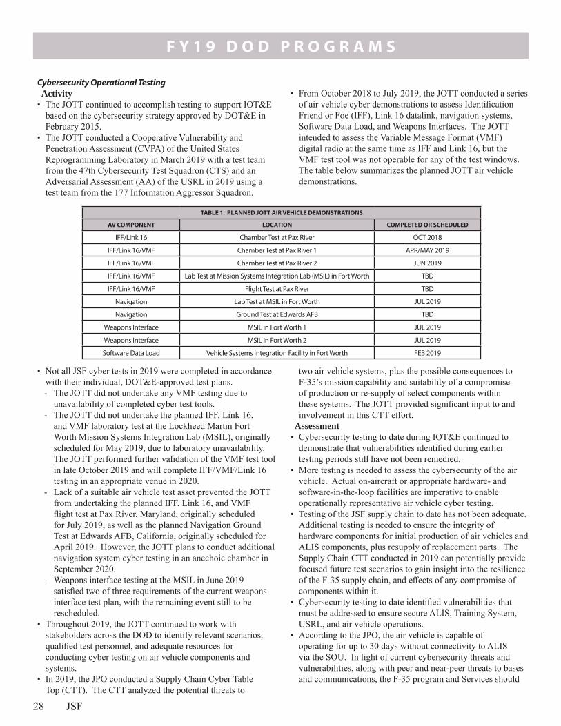
F Y 1 9 D O D P R O G R A M S
28 JSF
Cybersecurity Operational TestingActivity
• The JOTT continued to accomplish testing to support IOT&E based on the cybersecurity strategy approved by DOT&E in February 2015.
• The JOTT conducted a Cooperative Vulnerability and Penetration Assessment (CVPA) of the United States Reprogramming Laboratory in March 2019 with a test team from the 47th Cybersecurity Test Squadron (CTS) and an Adversarial Assessment (AA) of the USRL in 2019 using a test team from the 177 Information Aggressor Squadron.
• From October 2018 to July 2019, the JOTT conducted a series of air vehicle cyber demonstrations to assess Identification Friend or Foe (IFF), Link 16 datalink, navigation systems, Software Data Load, and Weapons Interfaces. The JOTT intended to assess the Variable Message Format (VMF) digital radio at the same time as IFF and Link 16, but the VMF test tool was not operable for any of the test windows. The table below summarizes the planned JOTT air vehicle demonstrations.
TABLE 1. PLANNED JOTT AIR VEHICLE DEMONSTRATIONS
AV COMPONENT LOCATION COMPLETED OR SCHEDULED
IFF/Link 16 Chamber Test at Pax River OCT 2018
IFF/Link 16/VMF Chamber Test at Pax River 1 APR/MAY 2019
IFF/Link 16/VMF Chamber Test at Pax River 2 JUN 2019
IFF/Link 16/VMF Lab Test at Mission Systems Integration Lab (MSIL) in Fort Worth TBD
IFF/Link 16/VMF Flight Test at Pax River TBD
Navigation Lab Test at MSIL in Fort Worth JUL 2019
Navigation Ground Test at Edwards AFB TBD
Weapons Interface MSIL in Fort Worth 1 JUL 2019
Weapons Interface MSIL in Fort Worth 2 JUL 2019
Software Data Load Vehicle Systems Integration Facility in Fort Worth FEB 2019
• Not all JSF cyber tests in 2019 were completed in accordance with their individual, DOT&E-approved test plans. - The JOTT did not undertake any VMF testing due to
unavailability of completed cyber test tools. - The JOTT did not undertake the planned IFF, Link 16,
and VMF laboratory test at the Lockheed Martin Fort Worth Mission Systems Integration Lab (MSIL), originally scheduled for May 2019, due to laboratory unavailability. The JOTT performed further validation of the VMF test tool in late October 2019 and will complete IFF/VMF/Link 16 testing in an appropriate venue in 2020.
- Lack of a suitable air vehicle test asset prevented the JOTT from undertaking the planned IFF, Link 16, and VMF flight test at Pax River, Maryland, originally scheduled for July 2019, as well as the planned Navigation Ground Test at Edwards AFB, California, originally scheduled for April 2019. However, the JOTT plans to conduct additional navigation system cyber testing in an anechoic chamber in September 2020.
- Weapons interface testing at the MSIL in June 2019 satisfied two of three requirements of the current weapons interface test plan, with the remaining event still to be rescheduled.
• Throughout 2019, the JOTT continued to work with stakeholders across the DOD to identify relevant scenarios, qualified test personnel, and adequate resources for conducting cyber testing on air vehicle components and systems.
• In 2019, the JPO conducted a Supply Chain Cyber Table Top (CTT). The CTT analyzed the potential threats to
two air vehicle systems, plus the possible consequences to F-35’s mission capability and suitability of a compromise of production or re-supply of select components within these systems. The JOTT provided significant input to and involvement in this CTT effort.
Assessment• Cybersecurity testing to date during IOT&E continued to
demonstrate that vulnerabilities identified during earlier testing periods still have not been remedied.
• More testing is needed to assess the cybersecurity of the air vehicle. Actual on-aircraft or appropriate hardware- and software-in-the-loop facilities are imperative to enable operationally representative air vehicle cyber testing.
• Testing of the JSF supply chain to date has not been adequate. Additional testing is needed to ensure the integrity of hardware components for initial production of air vehicles and ALIS components, plus resupply of replacement parts. The Supply Chain CTT conducted in 2019 can potentially provide focused future test scenarios to gain insight into the resilience of the F-35 supply chain, and effects of any compromise of components within it.
• Cybersecurity testing to date identified vulnerabilities that must be addressed to ensure secure ALIS, Training System, USRL, and air vehicle operations.
• According to the JPO, the air vehicle is capable of operating for up to 30 days without connectivity to ALIS via the SOU. In light of current cybersecurity threats and vulnerabilities, along with peer and near-peer threats to bases and communications, the F-35 program and Services should

F Y 1 9 D O D P R O G R A M S
JSF 29
conduct testing of aircraft operations without access to the ALIS SOU for extended periods of time, with an objective of demonstrating the 30 days of operations.
Availability, Reliability, and MaintainabilityActivity
• The program continued to deliver aircraft to the U.S. Services, international partners, and foreign military sales participants throughout CY19 in production Lot 11. As of the end of September, 430 aircraft had been produced for the U.S. Services, international partners, and foreign military sales. These aircraft are in addition to the 13 aircraft dedicated to developmental testing.
• The following assessments of fleet availability, reliability, and maintainability are based on sets of data collected from the operational and test units and provided by the JPO. The assessment of aircraft availability is based on data provided through the end of September 2019. Reliability and maintainability (R&M) assessments, with the exception of the Mean Flight Hours Between Maintenance Event (MFHBME), in this report are based on data covering the 12-month period ending June 13, 2019. Due to inconsistencies between the data from the June 2019 report compared to the February 2019 report, DOT&E did not consider the data from the June 2019 report for this metric to be reliable. Data for R&M include the records of all maintenance activity and undergo an adjudication process by the government and contractor teams, a process which creates a lag in publishing those data. The differences in data sources and processes create a disparity in dates for the analyses in this report.
• In September 2018, the Secretary of Defense directed the Services to increase fighter mission capable (MC) rates to 80 percent by the end of FY19. The MC rate represents the percentage of unit-assigned aircraft capable of performing at least one defined mission, excluding those aircraft in depot status or undergoing major repairs. MC aircraft are either Full Mission Capable (FMC), meaning they can perform all missions assigned to the unit, or Partial Mission Capable (PMC), meaning they can fly at least one, but not all, missions. The MC rate is different than the availability rate, which is the number of aircraft capable of performing at least one mission divided by all aircraft assigned, including aircraft in depot status or undergoing major repairs.
Assessment• The operational suitability of the F-35 fleet remains at a level
below Service expectations. However, after several years of remaining stable or only moving within narrow bands, several key suitability metrics showed signs of slow improvement in CY19.
• Aircraft availability is determined by measuring the percentage of time individual aircraft are in an “available” status, aggregated monthly over a reporting period. - The program-set availability goal is 65 percent; the
following fleet-wide availability discussion uses data from the 12-month period ending September 2019.
- For this report, DOT&E is reporting availability rates only for the U.S. fleet, vice including international partner and
foreign military sales aircraft, as was done in previous reports.
• The average fleet-wide monthly availability rate for only the U.S. aircraft, for the 12 months ending September 2019, is below the target value of 65 percent. However, the DOT&E assessment of the trend shows evidence of slight overall improvement in U.S. fleet-wide availability during 2019. In particular, while the average monthly availability for the 12 months ending September 2019 was only a few percent higher than the average monthly availability for the 12 months ending September 2018, the F-35 fleet’s monthly availability was generally slowly increasing in 2019, and achieved historic program highs that approached the target availability rate.
• The whole U.S. fleet can be broken down into three distinct sub-fleets: the combat-coded fleet of aircraft which are slated into units that can deploy for combat operations; the training fleet for new F-35 pilot accession; and the test fleet for operational testing and tactics development. The combat-coded fleet represented roughly a third of the whole U.S. fleet over the period, and demonstrated significantly higher availability than the other two fleets. The combat-coded fleet still fell short of the 65 percent monthly availability goal over the 12 months ending September 2019, but did achieve the goal each month for the last 3 months of FY19.
• Aircraft that are not available are designated in one of three status categories: Not Mission Capable for Maintenance (NMC-M), Depot (in the depot for modifications or repairs beyond the capability of unit-level squadrons), and Not Mission Capable for Supply (NMC-S). - The average monthly NMC-M and Depot rates were
relatively stable, with little variability, and near program targets.
- The average monthly NMC-S rate was more variable, and was higher (i.e., worse) than program targets. The NMC-S rate showed the greatest improvement over the period, however, and this improvement was largely responsible for the corresponding improvement in fleet-wide availability. The program should continue to resource and develop alternate sources of repair (including organic repair) for current and projected NMC-S drivers.
• The average monthly utilization rate measures flight hours per aircraft per month. The average utilization rate of flight hours per tail per month increased slightly over previous years, but remains below original Service beddown plans. - Low utilization rates continue to prevent the Services
from achieving their full programmed fly rates, which are the basis of flying hour projections and sustainment cost models. For the 12 months ending September 2019, the average monthly utilization rate for the whole U.S. fleet was 18.1 flight hours per tail per month for the F-35A, 15.3 for the F-35B, and 23.8 for the F-35C. This compares to Service bed-down plans from 2013, which expected F-35A and F-35C units to execute 25 flight hours per tail per month and F-35B units to execute 20 flight hours per tail per month to achieve Service goals.

F Y 1 9 D O D P R O G R A M S
30 JSF
• DOT&E conducted a separate analysis of availability of the fleet of operational test aircraft, using data from the 10-month period beginning December 2018, when formal IOT&E started, through September 2019. This assessment accounts for the full complement of 23 U.S. and international partner aircraft assigned to the OT fleet at the end of September 2019 (eight F-35A, nine F-35B, and six F-35C). - The average monthly availability rate for F-35 OT aircraft
was below the planned 80 percent needed for efficient conduct of IOT&E. However, judicious maintenance planning, test range scheduling, and effective mission execution allowed the JOTT to execute trials at a quicker pace than planned for worst-case scenario projections.
• No portion of the fleet, including the combat-coded fleet, was able to achieve and sustain the 80 percent MC rate goal set by former Secretary of Defense Mattis. However, individual units were able to achieve the 80 percent target for short periods during deployed operations. Similar to the trend in availability, the MC and FMC rates of the whole U.S. fleet improved slightly in 2019. FMC rates lagged the overall MC rates by a large margin, indicating low readiness for the mission sets requiring fully capable aircraft. All three variants achieved roughly similar MC rates, but significantly different FMC rates. The F-35A displayed the best FMC performance, while the F-35C fleet suffered from a particularly poor FMC rate; the F-35B’s FMC rate was roughly midway between the other two variants.
F-35 Fleet Reliability • Aircraft reliability assessments include a variety of metrics,
each characterizing a unique aspect of overall weapon system reliability. - Mean Flight Hours Between Critical Failure (MFHBCF)
includes all failures that render the aircraft unsafe to fly or would prevent the completion of a defined F-35 mission.
- Mean Flight Hours Between Removal (MFHBR) indicates the degree of necessary logistical support and is frequently used in determining associated costs.
- Mean Flight Hours Between Maintenance Event Unscheduled (MFHBME_Unsch) is a reliability metric
for evaluating maintenance workload due to unplanned maintenance.
- Mean Flight Hours Between Failure, Design Controllable (MFHBF_DC) includes failures of components due to design flaws under the purview of the contractor.
• The F-35 program developed reliability growth projection curves for each variant throughout the development period as a function of accumulated flight hours. These projections compare observed reliability with target numbers to meet the threshold requirement at maturity (200,000 total F-35 fleet flight hours, with a minimum of 50,000 flight hours per variant). In the program’s reliability growth plan, the target flight hour values were set at 75,000 flight hours each for the F-35A and F-35B, and 50,000 flight hours for the F-35C to establish the 200,000 flight hours of fleet maturity. The F-35A fleet reached 75,000 flight hours in July 2018 and had not reached ORD thresholds for reliability and maintainability at the time. DOT&E is continuing to track these metrics beyond the flight hours required for maturity of the F-35A fleet for reporting purposes. As of June 13, 2019, the date of the most recent set of reliability data available, the fleet and each variant accumulated the following flight hours, with the percentage of the associated hour count at maturity indicated: - The complete F-35 fleet accumulated 170,453 flight hours,
or 85 percent of its maturity value. - The F-35A accumulated 102,821 hours, or over 137 percent
of its target value in the reliability growth plan. - The F-35B accumulated 45,161 hours, or 60 percent of its
target value in the reliability growth plan. - The F-35C accumulated 22,471 hours, or 45 percent of its
target value in the reliability growth plan.• The program reports reliability and maintainability metrics for
the three most recent months of data. This rolling 3-month window dampens month-to-month variability while providing a short enough period to distinguish current trends.
• Table 2 shows the trend in each reliability metric by comparing values from June 2018 to those of June 2019 and whether the current value is on track to meet the requirement at maturity.
TABLE 2. F-35 RELIABILITY METRICS (UP ARROW REPRESENTS IMPROVING TREND)
Variant
Flight Hours
for ORD for JCS
Threshold
Assessment as of June 30, 2018
Cumulative Flight Hours
MRHBCF (Hours) MFHBR (Hours) MFHBME (hours)1 MFHBF_DC (Hours)
ORD Threshold
Change: June 2018
to June 2019
Meeting Interim
Goal for ORD
Threshold
ORD Threshold
Change: June 2018
to June 2019
Meeting Interim
Goal for ORD
Threshold
ORD Threshold
Change: June 2018
to June 2019
Meeting Interim
Goal for ORD
Threshold
JCS Require-
ment
Change: June 2018
to June 2019
Meeting Interim
Goal for ORD
Threshold
F-35A 75,000 102,821 20 ↓ No 6.5 ↓ No 2.0 ↓ No 6.0 ↓ Yes
F-35B 75,000 45,161 12 ↑ No 6.0 ↓ No 1.5 ↑ No 4.0 ↑ Yes
F-35C 50,000 22,471 14 ↑ No 6.0 ↑ No 1.5 ↑ No 4.0 ↑ Yes
1. For MFHBME, DOT&E assessment is based on data through February 2019 vice June 2019 due to inconsistencies in data reports.
• Between June 2018 and June 2019, three of the six ORD metrics increased in value, and three decreased. MFHBME decreased between June 2018 and February 2019 for
the F-35A and increased for the F-35B and F-35C. Unlike previous reports, however, two of the three JSF JCS metrics increased, while one decreased, and all three were

F Y 1 9 D O D P R O G R A M S
JSF 31
above interim goals. The improvement in MFHBF_DC reliability performance has still not translated into equally strong ORD reliability metric reliability performance, all of which fall short of their interim goals.
Maintainability• The amount of time needed to repair aircraft and return
them to flying status has changed little over the past year, and remains higher than the requirement for the system at maturity. The program assesses this time with several measures, including Mean Corrective Maintenance Time for Critical Failures (MCMTCF) and Mean Time To Repair (MTTR) for all unscheduled maintenance. Both measures include “active touch” labor time and cure times for coatings, sealants, paints, etc., but do not include logistics delay times, such as how long it takes to receive shipment of a replacement part.
TABLE 3. F-35 MAINTAINABILITY METRICS (DOWN ARROW REPRESENTS IMPROVING TREND)
Variant Flight Hours for ORD Threshold
Assessment as of June 13, 2019
Cumulative Flight Hours
MCMTCF (Hours) MTTR (Hours)
ORD ThresholdChange: June 2018 to June
2019
Meeting Interim Goal for ORD
ThresholdORD Threshold
Change: June 2018 to June
2019
Meeting Interim Goal for ORD Threshold
F-35A 75,000 93,356 4.0 ↓ No 2.5 ↓ No
F-35B 75,000 42,176 4.5 ↑ No 3.0 ↑ No
F-35C 50,000 20,505 4.0 ↓ No 2.5 ↓ No
Ship Integration• The Navy has started in-depth table top analyses of the
logistics footprint for the first carrier air-wing deployment that will include the F-35C onboard a nuclear-powered aircraft carrier. These analyses show that the air wing with the F-35C incorporated will bring a larger logistical footprint than legacy air wings, which may extend the timelines required and increase the risk to conduct certain shipboard flight and resupply operations. Not all of the cited increase in footprint is directly related to the F-35C since the planned air wing includes additional numbers of other types of aircraft. The air wing which has incorporated the F-35C also replaces the C-2 Carrier Onboard Delivery (COD) logistical support aircraft with the CMV-22B, since the latter can internal carry the F-135 power module to resupply F-35C engine components. The Navy analyses make several recommendations pertinent to the F-35C, that are consistent with DOT&E observations from F-35 ship integration testing conducted to date. Specifically these recommendations include: - The JPO and Navy continue to fund efforts to share
Support Equipment among multiple different types of aircraft, often called multipath. Previous DOT&E reports have shown that fleet personnel believe the F-35 Support Equipment, much of which is peculiar to the F-35, is much larger than legacy aircraft Support Equipment and will complicate shipboard maintenance evolutions.
- The JPO develop and provide environmental seals and covers for the F-135 power module when outside of its normal shipping pod, to ease transfer of un-podded power modules to and from the CMV-22B COD.
Live Fire Test and Evaluation F-35 Vulnerability to Kinetic Threats Activity
• In April 2018, Lockheed Martin delivered the F-35 Vulnerability Assessment Report summarizing the force protection and vulnerabilities of all three F-35 variants, and the F-35 Consolidated LFT&E Report, which summarizes the live fire test and analysis efforts supporting the vulnerability assessments.
Assessment• For three of the four specification threats, the F-35 variants
meet JSF contract specification requirements to enable safe ejection of the pilot in the event of an engagement.
• For two of the four specification threats, the F-35A and F-35C variants meet JSF contract specification requirements to return safely to the Forward Line of Troops following an engagement. The F-35B met the requirements for only one of the four threats.
• All three F-35 variants are less vulnerable to three of the four specification threats than the legacy F-16C aircraft, both for safe ejection and for return to Forward Line of Troops.
• The program reports maintainability metrics for the three most recent months of data. Table 3 shows the nominal change in each maintainability metric by comparing values from June 2018 to those of June 2019.
• All mean repair times are longer, some up to more than twice as long, as their original ORD threshold values for maturity, reflecting a heavy maintenance burden on fielded units.
• The JPO, after analyzing MTTR projections to maturity, acknowledged that the program would not meet the MTTR requirements defined in the ORD. The JPO sought and gained relief from the original MTTR requirements. The new values are 5.0 hours for both the F-35A and F-35C, and 6.4 hours for the F-35B. This will affect the ability to meet the ORD requirement for sortie generation rate, a Key Performance Parameter.

F Y 1 9 D O D P R O G R A M S
32 JSF
• DOT&E will publish an independent evaluation of the vulnerabilities of the F-35 aircraft variants to expected and emerging threats in the report to support the Full-Rate Production decision scheduled for FY21.
F-35 Vulnerability to Unconventional Threats Activity
• As of FY19, the Naval Air Warfare Center Aircraft Division at Naval Air Station Pax River, Maryland, completed system-level testing of F-35A and C variants, and limited testing of the F-35B, to evaluate tolerance to electromagnetic pulse (EMP) threats.
• The program completed full-up system-level, chemical-biological decontamination testing on BF-40 (a low-rate initial production F-35B aircraft) in February 2017.
Assessment• Testing was done to the threat level defined in Military
Standard 2169B. Follow-on, system-level tests of the F-35B, including a test series to evaluate Block 3F hardware and software changes, are anticipated.
• In the event of a chemical or biological attack, specialized equipment not readily available to deployed units is capable of decontaminating the F-35. Additional work would be needed to develop an operational decontamination capability.
• To assess the protection capability of the Gen II HMDS against chemical-biological agents, the JPO completed a comparison analysis of HMDS materials with those in an extensive DOD aerospace materials database. Compatibility testing of legacy protective ensembles and masks showed that the materials used in the protective equipment can survive exposure to chemical agents and decontamination materials and processes. The program plans similar analyses for the Gen III and Gen III Lite HMDS designs. While this assessment of material compatibilities provides some understanding of the force protection capability against chemical and biological agents, it does not demonstrate a process to decontaminate either HMDS.
F-35 Gun Lethality Activity
• From August through December 2017, during DT Weapons Delivery Accuracy testing, the Naval Air Warfare Center Weapons Division at Naval Air Weapons Station China Lake, California, completed air-to-ground flight lethality tests of three different 25-mm ammunitions: 1) Semi-Armor-Piercing High-Explosive Incendiary on the F-35B and F-35C only, 2) Armor-Piercing High-Explosive (APEX), and 3) Frangible Armor-Piercing on the F-35A only. Flight lethality tests included gun firings from all three F-35 variants against armored and technical vehicles, small boats, and plywood mannequins. Tests revealed deficiencies with the APEX fuze reliability for impacts into the ground. The manufacturer conducted follow-up testing on a new fuze design, but initial indications were that fuze reliability was not improved, and further APEX flights were grounded due to unexploded ordinance hazard range clean-up concerns.
Assessment• The Air Force delivered two of three required draft reports
to DOT&E covering ground and air-to-ground lethality tests spanning 2015-2018. DOT&E has provided the program with comments for revisions to satisfy DOT&E needs for the final lethality assessment.
Recommendations• The program (i.e., JPO, Services, Lockheed Martin) should:
1. Fully fund RSE, JSE, and OABS upgrades to meet test adequacy requirements in time for planned test periods.
2. Continue to work with the Services to prioritize and correct the remaining Category 1 and 2 deficiencies currently not corrected to ensure the SDD baseline configuration of software and hardware is stable prior to introducing the large number of new capabilities to the software in the new hardware configuration planned in Block 4.
3. Expedite fixes to Electronic Equipment Logbook data as it is a major ALIS degrader, frequent source of user complaints, and a major ALIS administrator burden.
4. Quickly complete the development of the requirements for the Block 4 software integration lab and USRL while ensuring adequate lab infrastructure to meet the aggressive development timelines of C2D2 and the operational requirements of the Block 4 F-35.
5. In light of the recent decision to not complete planned ALIS 3.6 and 3.7 releases, develop plans to deliver the remaining planned SDD capabilities and necessary deficiency fixes.
6. Develop and track appropriate metrics for ALIS to evaluate performance of future versions of ALIS.
7. Conduct more in-depth cyber testing of the air vehicle, and provide a dedicated air vehicle cyber-test asset.
8. Correct program-wide deficiencies identified during cybersecurity testing in a timely manner.
9. In collaboration with the Services, conduct testing of aircraft operations without access to the ALIS SOU for extended periods of time, with the objective of 30 days of disconnected operations.
10. Continue to resource and develop alternate sources of repair (including organic repair) for current and projected NMC-S drivers.
11. Continue to investigate multi-use opportunities for Support Equipment so that F-35’s can share Support Equipment with legacy aircraft in order to reduce logistics footprints for shipboard deployments.
12. Develop environmental seals and covers for un-podded F-35 power modules to ease transfer of resupply and retrograde power modules between the CVN and the CMV-22B carrier-onboard-delivery aircraft.
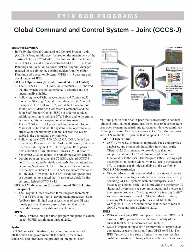
F Y 1 9 D O D P R O G R A M S
GCCS-J 33
real-time picture of the battlespace that is necessary to conduct joint and multi-national operations. Its client/server architecture uses open systems standards and government-developed military planning software. GCCS-J Operations, GCCS-J Modernization, and JPES are the three systems that comprise GCCS-J.
GCCS-J Operations• GCCS-J v6.0.1.2 is intended to provide back-end services,
databases, and system administration functions. Agile Client v5.2.0.2 is intended to provide visualization and presentation of GCCS-J mission applications and functionality to the user. The Program Office is using agile development to evolve Global v6.0.1.2, using incremental MRs to expand capabilities available to the warfighter.
GCCS-J Modernization• GCCS-J Modernization is intended to be a state-of-the-art
information technology solution that replaces the currently operating GCCS-J systems with one enterprise, cloud instance on a global scale. It will provide the warfighter C2 situational awareness via a common operational picture and intelligence products. The Program Office is using ”agile” software processes to develop GCCS-J Modernization, releasing PIs to expand capabilities available to the warfighter. GCCS-J Modernization is intended to replace GCCS-J v6.x and Agile Client v5.2.0.2.
JPES • DISA is developing JPES to replace the legacy JOPES v4.3
baseline. JPES provides all of the functionality of the current JOPES in a modernized architecture.
• DISA is implementing a JPES Framework to support dual operations, as users transition from JOPES to JPES. The JPES Framework is a suite of infrastructure services that enable information exchanges between the JOPES and two
Executive Summary• In FY19, the Global Command and Control System – Joint
(GCCS-J) Program Manager focused on the sustainment of the existing fielded GCCS-J v4.3.x baseline and the development of GCCS-J v6.x and a new modernized GCCS-J. The Joint Planning and Execution Services (JPES) Program Manager focused on sustaining the existing fielded Joint Operation Planning and Execution System (JOPES) v4.3 baseline and development of JPES.GCCS-J Operations (formerly named GCCS-J Global)• The GCCS-J v6.0.1.0 OT&E, in September 2018, showed
that the system was not operationally effective and not operationally suitable.
• Following the OT&E, the Command and Control (C2) Executive Steering Council (ESC) directed DISA to field the updated GCCS-J v6.0.1.2, with defect fixes, to three Joint Staff J3-identified Combatant Commands and the Joint Staff Support Center (JSSC) in order to conduct additional testing to validate OT&E fixes and to determine system stability in the operational environment.
• The GCCS-J v6.0.1.2 Operational Assessment (OA) in March 2019 showed that the system is not operationally effective or operationally suitable, nor was the system stable in the operational environment.
• Following the GCCS-J Ov6.0.1.2 OA, DISA fielded an Emergency Release to resolve 6 of the 10 Priority 2 defects discovered during the OA. The Program Office plans to field a number of Maintenance Releases (MRs) prior to September 2020 to address the remaining system defects.
• Despite poor test results, the C2 ESC declared GCCS-J v6.0.1.x operationally viable and ready for operational use beginning September 1, 2019. Users can choose not to use the new version of GCCS-J because the old version is still fielded. However, the C2 ESC ready for operational use determination started the 1-year sunset clock for the currently fielded GCCS-J v4.3.
GCCS-J Modernization (formerly named GCCS-J Joint Enterprise)• The Program Office released three Program Increments
(PI) in FY19, using “agile” development processes. User feedback from limited user assessments of each PI was mostly positive; however, users observed that many capabilities required additional development.
JPES• DISA is rebaselining the JPES program and plans to extend
legacy JOPES sustainment through 2022.
SystemGCCS-J consists of hardware, software (both commercial off-the-shelf and government off-the-shelf), procedures, standards, and interfaces that provide an integrated, near
Global Command and Control System – Joint (GCCS-J)

F Y 1 9 D O D P R O G R A M S
34 GCCS-J
- Build the air picture portion of the common operational picture
- Correlate or merge raw track data from multiple sources - Associate raw electronics intelligence data with track
data - Perform targeting operations
JPES• Commanders use JPES to:
- Translate policy decisions into operations plans that meet U.S. requirements to employ military forces
- Support force deployment - Conduct contingency and crisis action planning
Major Contractors• Government Integrator: DISA – Fort Meade, Maryland• Software Developers:
- Northrop Grumman – Arlington, Virginia - Leidos – Arlington, Virginia- InterImage – Arlington, Virginia- CSRA – Falls Church, Virginia
non-critical Global Force Management applications: the Joint Capabilities Requirements Manager (JCRM) and Preferred Force Generator (PFG).
MissionJoint Commanders utilize the GCCS-J to accomplish C2.
GCCS-J Operations and Modernization• Commanders use GCCS-J to:
- Link the National Command Authority to the Joint Task Force, Component Commanders, and Service-unique systems at lower levels of command
- Process, correlate, and display geographic track information integrated with available intelligence and environmental information to provide the user a fused battlespace picture
- Provide integrated imagery and intelligence capabilities (e.g., battlespace views and other relevant intelligence) into the common operational picture and allow commanders to manage and produce target data using the joint tactical terminal
- Provide a missile warning and tracking capability• Air Operations Centers use GCCS-J to:
ActivityGCCS-J Operations • The Program Office approved the following releases in
FY19: - v6.0.1.1 MR in December 2018 - v6.0.1.2 MR in February 2019 - v6.0.1.2 MR in April 2019 - v6.0.1.3 MR in June 2019
• The Joint Interoperability Test Command (JITC) conducted the GCCS-J v6.0.1.0 level II operational test at U.S. Central Command (USCENTCOM) and U.S. Indo-Pacific Command (USINDOPACOM) September 17 – 28, 2018, in accordance with a DOT&E-approved test plan.
• The C2 ESC determined that GCCS-J v6.0.1.0 was not ready for operational use on December 18, 2018.
• JITC conducted the GCCS-J v6.0.1.2 OA at USCENTCOM Headquarters, MacDill AFB, Florida; USINDOPACOM Headquarters, Camp H. M. Smith, Hawaii; U.S. Strategic Command (USSTRATCOM) Headquarters, Offutt AFB, Nebraska; and the JSSC, Defense Pentagon, Washington, D.C., from March through May 2019, in accordance with a DOT&E-approved test plan.
• Following the GCCS-J v6.0.1.2 OA, DISA fielded an Emergency Release to resolve 6 of the 10 Priority 2 defects discovered during the OA. The GCCS-J Program Office plans to field a number of MRs prior to September 2020 to address the remaining system defects. JITC plans to assess Program Office defect fixes in future MRs.
• Despite poor reliability, the C2 ESC declared GCCS-J v6.0.1.x operationally viable and ready for operational use beginning September 1, 2019. The C2 ESC ready for
operational use determination started the one-year sunset clock for the currently fielded GCCS-J v4.3.
• DOT&E released the report on the GCCS-J OA in November 2019.
• JITC is planning to conduct GCCS-J v6.0.1.2 cybersecurity testing in the first half of 2020.
GCCS-J Modernization• The Program Office approved the following releases in
FY19: - Modernization PI-1 in March 2019 - Modernization PI-2 in June 2019 - Modernization PI-3 in August 2019
• The Program Office conducted a system demonstration for each of the GCCS-J Modernization PIs prior to Government acceptance in March, June, and August 2019.
• JITC conducted a limited user assessment at the end of each GCCS-J Modernization PI to verify user-facing capabilities and collect user feedback in March, June, and August 2019.
JPES• DISA is rebaselining the JPES program and plans to extend
legacy JOPES sustainment through 2022.• The Program Office and JITC conducted a JPES
Framework Risk Reduction Event (RRE) at the Joint Staff J35, Norfolk, Virginia, and JSSC, Pentagon, Washington D.C., August 19 – 23, 2019. The purpose of the RRE was to evaluate JPES framework suitability in the operational environment and to reduce program risk prior to the JPES IOT&E.

F Y 1 9 D O D P R O G R A M S
GCCS-J 35
AssessmentGCCS-J Operations• The GCCS-J v6.0.1.0 OT&E showed that the system was
not operationally effective and not operationally suitable. Fifty-five problem reports remained open at the conclusion of OT&E, of which four resulted in complete or partial mission failure with no means to resolve and mitigate the deficiencies. JITC was not able to test 15 of 29 critical interfaces because they were not available at either test site. The system experienced failures on average every 3 hours, much less than the specified requirement. However, the system did demonstrate the ability to perform the majority of its design capabilities.
• Following the GCCS-J v6.0.1.0 OT&E, the C2 ESC determined that the system was not ready for operational use. The C2 ESC directed DISA to field the updated GCCS-J v6.0.1.2, with defect fixes, to multiple Combatant Commands and the JSSC in order to conduct additional testing to validate OT&E fixes and to determine system stability in the operational environment.
• The GCCS-J v6.0.1.2 OA showed that the system is not operationally effective or operationally suitable. Although USCENTCOM and USINDOPACOM validated the Program Office fixed 4 high priority and 17 lower priority defects found during OT&E, users discovered 21 new defects during the OA of which 10 resulted in complete or partial mission failure with no means to resolve or mitigate these deficiencies. DISA should have found many of these defects in developmental testing and resolved them prior to the OA. The OA also showed that GCCS-J v6.0.1.2 is not stable in the operational environment.
GCCS-J Modernization• GCCS-J Modernization demonstrations for the first three
PIs during FY19 showed that development is progressing as planned.
• User feedback from the GCCS-J Modernization limited user assessment was mostly positive; however, users observed
that many capabilities required additional development. Users also identified defects and requested enhancements, which DISA added to the backlog.
• PI 4 will focus on hardening the GCCS-J Modernization system to improve its cybersecurity posture in preparation for an Authority to Operate on the SIPRNET.
JPES• During the Program Office and JITC-conducted RRE,
system administrators installed and sustained the JPES Framework in the operational environment and successfully completed portions of the Continuity of Operations plan. The JPES Framework completed accurate, complete, and timely information exchanges with JOPES, JCRM, and PFG.
RecommendationsDISA should:
1. Resolve GCCS-J v6.0.1.2 Priority 1 and 2 problem reports and correct system stability problems.
2. Operationally test the system at USCENTCOM, USINDOPACOM, USSTRATCOM, and the JSSC prior to sunsetting the currently fielded GCCS-J v4.3.
3. Complete GCCS-J v6.0.1.2 interoperability testing of the remaining critical interfaces at Combatant Command sites.
4. Conduct cybersecurity testing on the operational version of Global v6.0.1.2, in accordance with DOT&E-approved cybersecurity test guidelines.
5. Review the GCCS-J developmental test program and develop options for improving the effectiveness of developmental testing across the C2 portfolio.

36
F Y 1 9 D O D P R O G R A M S

F Y 1 9 D O D P R O G R A M S
JIE 37
by the Defense Information Systems Agency (DISA) and the Military Services.
• In January 2017, the JIE EXCOM approved the following 10 JIE capability objectives:- Modernize Network Infrastructure, to include optical
carrier upgrades, multi-protocol label switching, satellite communication gateway modernization, and Internet Protocol (IP) version 6 implementation
- Enable Enterprise Network Operations, to include establishing global and regional operations centers, a JIE out-of-band management network, and converging IT service management solutions
- Implement Regional Security, to include the Joint Regional Security Stack (JRSS), and the Joint Management System for JRSS
- Provide MPE-Information System (IS) for coalition/partner information sharing, to include virtual data centers, services, and Mission Partner Gateways
Executive Summary• The Joint Information
Environment (JIE) Executive Committee (EXCOM) continued to provide guidance and direct the implementation of the funded initiatives supporting the 10 JIE capability objectives and integration efforts for the DOD.
• The Deputy SECDEF designated the Secretary of the Air Force as the DOD Executive Agent for Mission Partner Environment (MPE) capabilities in February 2019.
• The Air Force conducted a programmatic and technical assessment of the MPE portfolio and assumed responsibility in FY19.
• The USD(A&S) approved the Defense Enterprise Office Solution (DEOS) contract award in August 2019, which went under protest in September 2019, and now has an anticipated contract award in January/February 2020. The DEOS program plans to use commercial cloud platforms to store classified and unclassified data.
• In 2019, the DEOS Program Management Office (PMO) and the Joint Interoperability Test Command prepared the DEOS Phase 1 Test and Evaluation Master Plan (TEMP) that is in staff review for approval in FY20.
• DOT&E has stressed the need for DOD to conduct threat-representative cybersecurity testing on commercial cloud platforms to be used by DEOS.
Capability and Attributes• In August 2012, the Joint Chiefs of Staff (JCS) approved the
JIE concept as a secure environment, comprising a single security architecture, shared information technology (IT) infrastructure, and enterprise services.
• The JCS intend JIE to consist of multiple subordinate programs, projects, and initiatives managed and implemented
Joint Information Environment (JIE)

F Y 1 9 D O D P R O G R A M S
38 JIE
physical infrastructure, increase the use of enterprise services, improve IT effectiveness, and centralize the management of network defense. The Joint Staff specifies the following enabling characteristics for JIE capability objectives:- Transition to centralized data storage- Rapid delivery of integrated enterprise services (such as
email and collaboration)- Real-time cybersecurity awareness- Scalability and flexibility to provide new services- Use of common standards and operational techniques- Transition to the JIE Cybersecurity Architecture
• JIE is not a program of record and does not have a traditional milestone decision authority, program executive organization, and project management structure that would normally be responsible for the cost, schedule, and operational performance of a program.
• The DOD Chief Information Officer (CIO) is the overall lead for JIE efforts with support from the JIE EXCOM – chaired by the DOD CIO, U.S. Cyber Command, and Joint Staff J6. The EXCOM provides JIE direction and objectives. DISA is the principal integrator for JIE capabilities and testing.
- Optimize Data Center Infrastructure- Implement Consistent Cybersecurity Architecture/
Protections, to include DOD enterprise perimeter protection, endpoint security, mobile endpoint security, data center security, cybersecurity situational awareness analytic capabilities, and identity and access management (referred to as the Single Security Architecture in older JIE documentation)
- Enhance Mobility for unclassified and classified capabilities
- Standardized IT Commodity Management, to include enterprise software agreements, license agreements, hardware agreements, and IT asset management
- Establish End-User Enterprise Services, to include the Enterprise Collaboration and Productivity Services (ECAPS) and converged voice and video services over IP
- Provide Hybrid Cloud Computing Environments, to include Commercial Cloud, Cloud Access Points, and milCloud
• The JCS envision JIE as a shared information technology construct for DOD to reduce costs, improve and standardize
ActivityJIE• For the JRSS version 1.5 operational assessment completed
in July 2019, see the JRSS article on page 41.• The JIE EXCOM continued to provide guidance and direct
the implementation of the funded initiatives supporting the 10 JIE capability objectives and integration efforts for the DOD.
• The DOD CIO, Joint Staff, Combatant Commands, Services, and DOD Agencies continued efforts to collaboratively develop and build the JIE Cybersecurity Architecture.
ECAPS• In 2019, the DEOS (ECAPS capability set 1) PMO and the
Joint Interoperability Test Command prepared the DEOS Phase 1 TEMP that is in staff review for approval in FY20.
• In August 2019, the USD(A&S) approved the DEOS contract award, which then went under protest in September 2019, and now has an anticipated contract award in January/February 2020.
• DOT&E placed DEOS on the Operational Test Oversight List in September 2019.
• In coordination with the DOD CIO, the USD(A&S) is evaluating and refining the ECAPS capability sets 2 and 3 requirements through 2QFY20.
MPE• The Deputy SECDEF designated the Secretary of the
Air Force as the DOD Executive Agent for MPE and the DOD CIO as the Principal Staff Assistant for MPE in February 2019.
• The intent is to rationalize and modernize the overall MPE portfolio of command and control, and intelligence information sharing capabilities.
• The MPE-IS initiative is intended to consolidate and recapitalize 28 physical Combined Enterprise Regional Information Exchange Systems across the DOD, providing virtualized enduring and episodic MPE-IS services tailored to meet mission partner information sharing needs.
• The Air Force conducted a programmatic and technical assessment of the MPE portfolio and assumed responsibility in FY19.
Assessment • The DOD CIO, DISA, and Services intend to achieve the JIE
objectives through implementation of enabling initiatives aligned under the JIE EXCOM approved and funded priorities.
• The JIE EXCOM has started efforts to monitor JIE capability performance factors; however, the EXCOM does not place high enough priority on developmental and operational test results to inform decisions.
• The accelerated and compressed DEOS Phase 1 schedule is overly aggressive and high risk such that little time is factored in to find and resolve functional and cybersecurity problems before advancing to the next test and fielding event.
• Because the DEOS program plans to use commercial cloud platforms to store classified and unclassified data, it will be critical for DOD to conduct threat-representative cybersecurity

F Y 1 9 D O D P R O G R A M S
JIE 39
testing on the commercial cloud and its hosting infrastructure. This will require appropriate agreements between the DOD and chosen cloud service providers.
• The DEOS PMO has not planned or contracted for a DEOS integration lab to provide an operationally representative environment, so all DEOS developmental, cybersecurity, and operational testing will be conducted on production networks.
RecommendationsThe DOD CIO, JIE EXCOM, Services, and Director of DISA should:
1. Conduct thorough cybersecurity operational testing of all JIE capabilities, including threat-representative testing of the commercial cloud capabilities employing current cybersecurity testing guidance and policy.
2. Use operational test information, such as that from the recent JRSS operational assessment, to inform JIE decisions.
3. Update the MPE-IS Test and Evaluation Strategy based on the Air Force programmatic and technical assessment.
4. Update the DEOS Phase 1 TEMP based on the contract award and update the master schedule.
5. Revise the DEOS schedule to make it supportable, resourced, and event-driven to guide both the capability development and the testing approach.
6. Establish an operationally representative DEOS integration lab for conducting developmental testing and initial cybersecurity assessments.
7. Develop the DEOS Phases 2, 3, and 4 TEMP Addenda to prepare stakeholders for the remaining deliveries, resource commitments, and T&E goals.
8. Develop a TEMP for ECAPS capability sets 2 and 3, and more generally for each JIE capability objective with funded initiatives.

40
F Y 1 9 D O D P R O G R A M S

F Y 1 9 D O D P R O G R A M S
JRSS 41
• The DOD intends to deploy JRSS on both the NIPRNET (N-JRSS) and SIPRNET (S-JRSS).
• DISA is the designated approving and certification authority for both JRSS equipment and multiprotocol label switching (MPLS) equipment. MPLS is part of a modernization effort to upgrade the bandwidth capacity of the Defense Information Systems Network.
• A key component of JRSS is the Joint Management System (JMS), which provides centralized management of cybersecurity services required for DOD Information Network (DODIN) operations and defensive cyber operations.
MissionThe DOD intends to use JRSS to enable DOD cyber defenders to continuously monitor and analyze the DODIN for increased situational awareness to minimize the effects of cyber-attacks while ensuring the integrity, availability, confidentiality, and non-repudiation of data.
Executive Summary• The Joint Interoperability Test Command (JITC)
conducted an operational assessment (OA) of the NIPRNET-Joint Regional Security Stack (JRSS) (N-JRSS) in July 2019, in accordance with a DOT&E-approved test plan. The Air Force, Army, Navy, Coast Guard, and the Defense Information Systems Agency (DISA) Global participated in the event. Preliminary results show that JRSS continues to perform poorly against operationally realistic cyber-attacks on DOD networks.
• Migrations to use N-JRSS have continued and are not contingent upon operational test results, but the DOD Chief Information Officer (CIO) and the JRSS Program Manager (PM) use test results to track problems with the fielded system. Thirteen JRSSs are currently operational on the NIPRNET with 20 total planned for fielding.
• Operator proficiency is a persistent shortfall identified by operational testing, indicating the JRSS training processes and system usability need improvement.
• Despite the above, the DOD plans to deploy JRSS on the DOD classified SIPRNET. DOT&E is working with the JRSS PM and the DOD CIO to plan cybersecurity assessment activity to inform the SIPRNET-JRSS (S-JRSS) trial migration decisions scheduled in FY20. This effort will also help develop and validate S-JRSS joint operator tactics, techniques, and procedures (TTPs), which are currently in development. The PM plans to field a total of 25 S-JRSSs.
Capabilities and Attributes• As a component of the Joint Information Environment (JIE),
JRSS is a suite of equipment intended to perform firewall functions, intrusion detection and prevention, enterprise management, and virtual routing and forwarding, as well as to provide a host of network security capabilities. JRSS is not a program of record. Despite its complexity, the DOD has treated JRSS as a “technology refresh,” and has not funded the personnel and training typically associated with DOD acquisition programs of record.
• The JRSS is intended to centralize and standardize network security into regional architectures instead of locally distributed, non-standardized architectures at different levels of maturity and different stages in their lifecycle at each military base, post, camp, or station.
• Each JRSS includes many racks of equipment designed to allow DOD components to ingest, process, and analyze very large network data flows.
Joint Regional Security Stack (JRSS)

F Y 1 9 D O D P R O G R A M S
42 JRSS
VendorsDISA is the lead integrator for JRSS. The tables below list the current Original Equipment Manufacturers (OEMs) of the JRSS capabilities.
OEM OEM Location
A10 San Jose, California
Argus Houston, Texas
Axway Phoenix, Arizona
Bivio Pleasanton, California
BMC Houston, Texas
Bro Berkeley, California
Cisco San Jose, California
Citrix Fort Lauderdale, Florida
CSG International Alexandria, Virginia
Dell Round Rock, Texas
EMC Santa Clara, California
F5 Seattle, Washington
Fidelis Bethesda, Maryland
Gigamon Santa Clara, California
HP Palo Alto, California
IBM Armonk, New York
InfoVista Ashburn, Virginia
InQuest Arlington, Virginia
Juniper Sunnyvale, California
OEM OEM Location
Micro Focus Rockville, Maryland
Microsoft Redmond, Washington
Niksun Princeton, New Jersey
OPSWAT San Francisco, California
Palo Alto Santa Clara, California
Quest Aliso Viejo, California
Raritan Somerset, New Jersey
Red Hat Raleigh, North Carolina
Red Seal Sunnyvale, California
Riverbed San Francisco, California
Safenet Belcamp, Maryland
Splunk San Francisco, California
Symantec Mountain View, California
Trend Micro Irving, Texas
Van Dyke Albuquerque, New Mexico
Veeam Columbus, Ohio
Veritas Mountain View, California
VMWare Palo Alto, California
• In July/August 2019, the JRSS PM and JITC conducted an OA on N-JRSS as a risk reduction event in accordance with a DOT&E-approved test plan to assess Air Force, Army, and Navy JRSS instantiations and to validate resolution of a subset of problem reports identified during previous tests. Of the 17 problem reports assessed, 8 were closed, 9 remain open, and 5 new reports were created. The Coast Guard participated, but was not evaluated.
• In October 2019, the JRSS PM and the DOD CIO, in collaboration with DOT&E, began planning cybersecurity assessment activity to inform S-JRSS trial migration decisions in FY20, and to inform the development of S-JRSS joint TTPs.
Assessment• Analysis of the July/August 2019 OA is ongoing. JITC
conducts OAs every 6 months in a schedule-driven approach that does not allow sufficient time to report on findings, correct problems, and update test plans.
• Preliminary OA results indicated that JRSS continues to perform poorly against operationally realistic cyber-attacks on DOD networks.
Activity• Because of problems found with fielded N-JRSS during
operationally realistic testing, in 2018, the JIE Executive Committee directed a JRSS Strategic Review and subsequent actions to address shortfalls in training, migration, system performance, JRSS on SIPRNET, and operational processes. These actions concluded in early CY19.
• In December 2018, the JRSS Senior Advisory Group (SAG) requested that the DOD CIO staff and the JRSS PM conduct one-on-one meetings with each Service to ascertain their problem priorities for correction. The PM continues to work corrective actions for the problems identified by the Services.
• JITC conducted a JRSS Operations Rehearsal (OR) in January/February 2019. JITC had planned the event as an OA, but de-scoped the assessment to a rehearsal after the planned Red Team became unavailable. The JRSS OR focused on 10 open problem reports from previous events. JITC assessed that four problems had been corrected and discovered two new problems.
• In March 2019, the JRSS SAG directed JITC to propose updated Measures of Performance to be used in the July 2019 OA, which the SAG endorsed in early July 2019.
• In March 2019, a Red Team began aggressing Service networks protected by JRSS to establish network presence over the course of 4 months.

F Y 1 9 D O D P R O G R A M S
JRSS 43
• The OA provided useful Service user feedback:- Some test scenarios did not accurately represent the various
ways in which different Services use the JRSS.- New users wanted better training to understand how JRSS
should be configured and used to support their missions. The OA revealed that user training continues to be insufficient, as Service users had gaps in their knowledge of various JRSS tools.
- Service users do not have good insight into the status of their trouble tickets or the ticket resolution process.
• The extended Red Team activity, executed in support of the OA, was more limited in duration and scope than a Persistent Cyber Opposing Force assessment, but provided an informative prototype for future instantiations of such an effort.
• The JRSS PM and DOD CIO are engaging in efforts to improve current JRSS configurations, training, and procedures, and to migrate new users to N-JRSS and S-JRSS. Testing has enabled the JRSS PM to identify improvements and correct problems with the fielded system. However, capability deployment and user migrations are not contingent upon proven performance in operationally realistic testing.
• JITC has not conducted a Cooperative Vulnerability and Penetration Assessment or Adversarial Assessment on JRSS components or their associated management networks. These assessments are necessary to resolve the cybersecurity posture of the stacks themselves. JITC is planning to conduct these assessments for the first time on N-JRSS in FY20.
• Outside of operational test events, routine cyber assessments on networks protected by JRSSs, such as using a threat-representative Persistent Cyber Opposing Force, are not being conducted. Doing so would help program efforts to discover and address critical cyber vulnerabilities, and provide continual feedback on JRSS network defense effectiveness against operationally realistic cyber-attacks.
• JRSS test requirements derive from a Functional Requirements Document that the DOD CIO and U.S. Cyber Command (USCYBERCOM) have not updated as operational needs and funding priorities have evolved. JITC has also not updated the JRSS Test and Evaluation Strategy to reflect changing priorities.
• The JRSS PM and DOD CIO have not initiated a Validated Online Lifecycle Threat (VOLT) assessment analysis with the Defense Intelligence Agency (DIA) in accordance with DOD policy. Doing so would support PMO assessments of capability gaps against likely threat capabilities.
• The results of the 1QFY20 pre-migration cybersecurity assessment of S-JRSS will provide critical entrance criteria to the formal migration decisions.
Recommendations• The DOD CIO and the DOD Components should:
1. Discontinue migrating new users to JRSSs until the system demonstrates that it is capable of helping network defenders to detect and respond to operationally realistic cyber-attacks.
2. Prioritize training, system usability, and operator proficiency over meeting migration schedule deadlines.
3. Engage with USCYBERCOM and Joint Force Headquarters (JFHQ)-DODIN to establish a process to regularly update the Functional Requirements Document to reflect Service requirements, funding availability, and project capability needs identified by the mission owners.
4. Engage with USCYBERCOM and JFHQ-DODIN to produce an operational requirements document.
5. Coordinate with JITC to update the JRSS Test and Evaluation Strategy to support capability implementation and DOD Component requirements.
• The JRSS PM, DISA Global, and the DOD Components should: 1. Use operationally realistic test results to improve current
JRSS configurations, training, and procedures, and to inform future N-JRSS and S-JRSS migration decisions.
2. Address any new problems discovered during the recent July/August 2019 OA and from previous testing.
3. Formalize and promulgate a joint problem reporting and tracking system for problems discovered in both tests and in real-world operations to allow user visibility and cross-Component situational awareness into the status of known unresolved and resolved problems.
• DISA and the DOD Components should:1. Verify JRSS operator competency and training to properly
configure and use JRSS services prior to new user migrations.
2. Engage with JFHQ-DODIN to include JRSS in upcoming Persistent Cyber Opposing Force efforts to routinely discover and address critical cyber vulnerabilities on operational networks.
• DISA (JRSS PM), DOD Components, and JITC should:1. Conduct a review of the test scenarios and measures to
ensure that each Components’ unique testing needs are met and that inconsistencies between test scenarios and DOD Components’ actual procedures are minimized.
2. Plan to conduct Cooperative Vulnerability and Penetration Assessments and Adversarial Assessments of the N-JRSS and S-JRSS stacks and their associated management networks.
• DISA (JRSS PM) should:1. Engage with DIA for a VOLT analysis, which can be used
to inform the Adversarial Assessment efforts planned for FY20 and beyond.

44
F Y 1 9 D O D P R O G R A M S
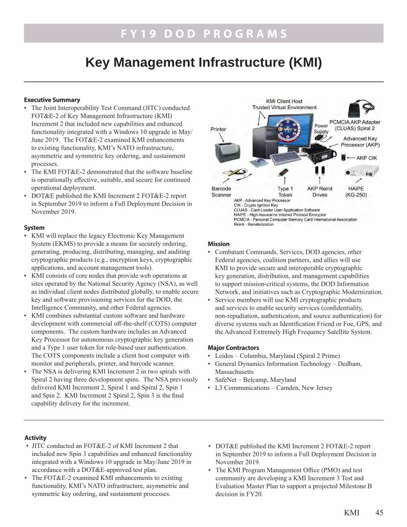
F Y 1 9 D O D P R O G R A M S
KMI 45
• DOT&E published the KMI Increment 2 FOT&E-2 report in September 2019 to inform a Full Deployment Decision in November 2019.
• The KMI Program Management Office (PMO) and test community are developing a KMI Increment 3 Test and Evaluation Master Plan to support a projected Milestone B decision in FY20.
Activity • JITC conducted an FOT&E-2 of KMI Increment 2 that
included new Spin 3 capabilities and enhanced functionality integrated with a Windows 10 upgrade in May/June 2019 in accordance with a DOT&E-approved test plan.
• The FOT&E-2 examined KMI enhancements to existing functionality, KMI’s NATO infrastructure, asymmetric and symmetric key ordering, and sustainment processes.
Mission• Combatant Commands, Services, DOD agencies, other
Federal agencies, coalition partners, and allies will use KMI to provide secure and interoperable cryptographic key generation, distribution, and management capabilities to support mission-critical systems, the DOD Information Network, and initiatives such as Cryptographic Modernization.
• Service members will use KMI cryptographic products and services to enable security services (confidentiality, non-repudiation, authentication, and source authentication) for diverse systems such as Identification Friend or Foe, GPS, and the Advanced Extremely High Frequency Satellite System.
Major Contractors• Leidos – Columbia, Maryland (Spiral 2 Prime)• General Dynamics Information Technology – Dedham,
Massachusetts• SafeNet – Belcamp, Maryland• L3 Communications – Camden, New Jersey
Executive Summary• The Joint Interoperability Test Command (JITC) conducted
FOT&E-2 of Key Management Infrastructure (KMI) Increment 2 that included new capabilities and enhanced functionality integrated with a Windows 10 upgrade in May/June 2019. The FOT&E-2 examined KMI enhancements to existing functionality, KMI’s NATO infrastructure, asymmetric and symmetric key ordering, and sustainment processes.
• The KMI FOT&E-2 demonstrated that the software baseline is operationally effective, suitable, and secure for continued operational deployment.
• DOT&E published the KMI Increment 2 FOT&E-2 report in September 2019 to inform a Full Deployment Decision in November 2019.
System• KMI will replace the legacy Electronic Key Management
System (EKMS) to provide a means for securely ordering, generating, producing, distributing, managing, and auditing cryptographic products (e.g., encryption keys, cryptographic applications, and account management tools).
• KMI consists of core nodes that provide web operations at sites operated by the National Security Agency (NSA), as well as individual client nodes distributed globally, to enable secure key and software provisioning services for the DOD, the Intelligence Community, and other Federal agencies.
• KMI combines substantial custom software and hardware development with commercial off-the-shelf (COTS) computer components. The custom hardware includes an Advanced Key Processor for autonomous cryptographic key generation and a Type 1 user token for role-based user authentication. The COTS components include a client host computer with monitor and peripherals, printer, and barcode scanner.
• The NSA is delivering KMI Increment 2 in two spirals with Spiral 2 having three development spins. The NSA previously delivered KMI Increment 2, Spiral 1 and Spiral 2, Spin 1 and Spin 2. KMI Increment 2 Spiral 2, Spin 3 is the final capability delivery for the increment.
Key Management Infrastructure (KMI)

F Y 1 9 D O D P R O G R A M S
46 KMI
Assessment • The KMI FOT&E-2 demonstrated that the software baseline
is operationally effective, suitable, and secure for continued operational deployment. The KMI performance is summarized below: - The NSA included a Windows 10 upgrade and system
integration in the FOT&E-2 using upgraded scripts that performed near flawlessly and were notably improved over previous installation scripts.
- KMI system documentation, Service help desks, and training were adequate to support the mission.
- KMI had problems synchronizing common account data for cryptographic product transfers from some Navy and all NATO accounts to non-KMI (manual) accounts.
- The secure software provisioning capability that allows users to download information assurance vulnerability alerts had slow delivery.
- NSA KMI Operations temporarily surged manning for the operational test and has recurring staffing shortages that affect long-term system sustainment.
- The NSA KMI help desk, which supports DOD agency and external (non-DOD) users, lacks adequate knowledge of the system and is subject to high staff turnover rates.
- Long-standing KMI configuration management problems remain that require experienced system and database administration, rigid process adherence, adequate staffing,
and monitoring to sustain configuration consistency between core nodes throughout the KMI lifecycle.
• The KMI Test Infrastructure (TI) provides a safe laboratory for evaluating KMI software builds; however, the KMI TI is not maintained in the same configuration as the operational KMI. This limits the KMI TI’s ability to accurately identify problems prior to deploying a new KMI version to the operational system.
Recommendations • The KMI PMO should:
1. Continue to resolve system defects and sustainment problems.
2. Maintain the KMI TI to the same degree as the operational environment.
• The NSA KMI Operations should: 1. Improve KMI configuration management and long-term
sustainment.2. Reassess KMI Operations and help desk staffing to ensure
that it can support all existing and planned new capabilities, networks, sites, and users.

F Y 1 9 D O D P R O G R A M S
PKI 47
- The NPE system issues certificates to large numbers of network devices (e.g., routers and web servers) using both manual and automated methods. These certificates help ensure only authorized devices are allowed to access DOD networks. NPE provides authorized System Administrators and Registered Sponsors with the capability to issue device certificates singularly or in bulk without the need for PKI registration authority approval.
- The NSA manages the NEATS and NPE with operational support from DISA, which hosts the infrastructure and provides PKI support for the DOD, and the Defense Manpower Data Center (DMDC). DMDC also manages the Defense Enrollment Eligibility Reporting System for the NIPRNET and Secure Defense Enrollment Eligibility Reporting System for the SIPRNET, the authoritative sources for personnel data.
- NPE and NEATS use commercial and government off-the-shelf hardware and software hosted at DISA and DMDC sites.
Executive Summary• The Joint Interoperability Test Command
(JITC) conducted a Limited User Test (LUT) of the Public Key Infrastructure (PKI) Increment 2, focusing on Spiral 4 capabilities, in September/November 2019 to reduce risk and inform a planned Limited Deployment Decision in late February/March 2020.
• The PKI Program Management Office (PMO) and Defense Information Systems Agency (DISA) plan to migrate the Token Management System (TMS) from the DISA physical hosting to a virtualized environment in February/March 2020.
• JITC plans to conduct an OT&E of the new DISA virtual server solution for TMS in March/May 2020 to inform a decision to cutover to a new server.
System• DOD PKI provides for the generation,
production, distribution, control, revocation, recovery, and tracking of public key certificates and their corresponding private keys. By controlling the distribution of encryption, identity, signing, and device certificates and keys, DOD PKI helps ensure only authorized individuals and devices have access to networks and data, which supports the secure flow of information across the DOD Information Network as well as secure local storage of information.
• The National Security Agency (NSA) deployed PKI Increment 1 on the NIPRNET with access control provided through Common Access Cards (CACs) issued to authorized personnel.
• The NSA is developing and deploying PKI Increment 2 in four spirals on SIPRNET and NIPRNET. The NSA delivered the SIPRNET TMS in Spirals 1, 2, and 3. Spiral 4 is intended to deliver the NIPRNET Enterprise Alternate Token System (NEATS) and Non-Person Entity (NPE) capabilities.- NEATS is intended to provide confidentiality, integrity,
authentication, and nonrepudiation services by providing a centralized system for the management of NIPRNET certificates on NEATS tokens for privileged users, which includes System Administrators, groups, roles, code signing, and individuals not eligible to receive CACs. NEATS will provide token registration, issuance, personnel identification number reset, revocation, and key recovery. The private keys are encoded on the token, which is a smartcard embedded with a microchip.
Public Key Infrastructure (PKI) Increment 2

F Y 1 9 D O D P R O G R A M S
48 PKI
network domains, which will facilitate intrusion protection and detection.
Major Contractors• General Dynamics Mission Systems – Dedham, Massachusetts
(Prime for TMS and NPE)• Global Connections to Employment – Lorton, Virginia (Prime
for NEATS)• SafeNet Assured Technologies – Abington, Maryland• Giesecke and Devrient America – Twinsburg, Ohio
Mission• Commanders at all levels will use DOD PKI to provide
authenticated identity management via personal identification number-protected CACs, SIPRNET or NEATS tokens to enable DOD members, coalition partners, and other authorized users to access restricted websites, enroll in online services, and encrypt and digitally sign email.
• Military operators, communities of interest, and other authorized users will use DOD PKI to securely access, process, store, transport, and use information, applications, and networks.
• Military network operators will use NPE certificates for workstations, web servers, and devices to create secure
Activity • JITC conducted a PKI Increment 2 operational assessment
in November/December 2018 as a risk reduction event to evaluate the Spiral 4 NPE and NEATS capabilities, but found the systems were not ready for the FOT&E.
• JITC conducted a cybersecurity verification of deficiency corrections of PKI Increment 2, Spiral 4 capabilities in December 2018.
• In February 2019, the PKI PMO delayed the PKI Increment 2 FOT&E to resolve high-priority Spiral 4 system defects and integration problems found in the operational assessment and subsequent continuous monitoring, as well as cybersecurity findings.
• In accordance with a DOT&E-approved test plan, JITC conducted a LUT of all Increment 2 capabilities, including the new Spiral 4 NPE and NEATS functionalities in September/November 2019. The LUT examined the NEATS on NIPRNET and the NPE enterprise certificate issuance and management system deployed in both the NIPRNET and SIPRNET environments.
• The PKI PMO changed the estimated Increment 2 Full Deployment Decision from October 2018 to late January 2020, but the PMO will likely change the Full Deployment Decision estimate to late 2020/2021.
• The PKI PMO and DISA plan to migrate TMS from the DISA physical hosting to a virtualized environment in February/March 2020.
• JITC intends to conduct an OT&E of the new DISA virtual server solution for TMS in March/May 2020 to inform a decision to cutover to a new server.
Assessment • Problems associated with PKI Increment 2, Spiral 4 NPE and
NEATS capabilities found in developmental and integrated testing, and the operational assessment events affected preparations for operational testing. - The NEATS and NPE functionality continues to improve;
but processes, interfaces, and sustainment were immature and not ready for operational testing.
- The DISA and DMDC help desks were not prepared to support the PKI Spiral 4 capabilities operationally.
• TMS stability, NPE and NEATS capability problems, and the lack of operationally representative NPE devices caused several test event schedule slips.
• The NPE test effort is handicapped because vendors have not fully implemented protocols for device enrollment, so the Key System Attribute to auto-rekey devices is unlikely to be met. - With assistance from the DOD Chief Information
Officer (CIO), the PKI PMO continues investigating and identifying devices that will support the NPE protocols.
• The proposed NPE integration efforts provide limited, semi-automated protocol solutions that likely will not satisfy the greater NPE requirement needs of the DOD, which include an as yet unknown, and much broader, range of devices.
• The NSA established a token evaluation process and chartered a token evaluation working group to address token compatibility problems found in operational use and testing; however, the NSA has yet to fully document or follow the formal security certification assessment process prior to deploying new PKI tokens.
Recommendations• The DOD and Service CIOs should:
1. Develop DOD enterprise NPE policy and implementation guidance for automated device enrollment.
• The PKI PMO and DISA should:1. Continue to resolve all high-priority defects and verify
acceptability to users prior to the PKI Increment 2 Full Deployment Decision.
2. Establish a dedicated transition working-level integrated product team to address sustainability and logistics problems through transition to DISA and DMDC.
3. Coordinate with the DOD CIO to issue NPE guidance for the Services and Agencies on the intended NPE approach for enterprise-wide Certificate Authorities and devices.
4. Complete full security certification testing for new PKI tokens, and rigorously follow the certification process for all future token variants to ensure that new tokens are secure prior to deploying them into the operational environment.

F Y 1 9 D O D P R O G R A M S
IT&E 49
DOT&E, under the authority of section 2350(1), title 10, U.S. Code in 2001, manages the International Test and Evaluation Program (ITEP) for the DOD. This program directly aligns with the FY18 National Defense Strategy third Line of Effort—strengthen alliances and attract new partners. ITEP bilateral and multilateral agreements allow for Cooperative Test and Evaluation (CTE) Project Arrangements (PAs); Equipment and Material Transfers; Working Groups; and Reciprocal Use of Test and Facilities (RUTF) PAs. These projects benefit the United States and our allied partners by enabling access to environments and facilities to achieve coalition and joint force operational realism; sharing T&E technologies, data, and costs; and standardizing test and analytical procedures. The United States has bilateral agreements with 11 allied partners and 1 five-nation agreement, the Multinational Test and Evaluation Program (MTEP). During FY19, IT&E discussions reached advanced stages to establish a new bilateral agreement with another foreign partner. Discussions also progressed on establishing a Trans-Atlantic MTEP, involving France, Germany, Italy, the United Kingdom (UK), and the United States. The agreement is structured so more countries could be added after it is implemented. In FY19, DOT&E approved one CTE and nine RUTF PAs. One RUTF PA allowed the U.S. Navy to conduct unique integration testing using a coalition partner’s ship. Taking place in March 2019 off the coast of Virginia, the U.S. Navy deployed several different unmanned, next generation mine countermeasures (MCM) assets and sensors on board the British Royal Fleet Auxiliary (RFA) Landing Ship Dock Auxiliary Mounts Bay (Figure 1). In this event, the U.S. Navy’s MCM community tested its ability to command and control MCM operations. RUTF PAs, such as this one, are not available under any other international agreement.
International Test and Evaluation (IT&E)
Under another RUTF PA, the U.S. Navy completed complex missile defense testing on the UK Hebrides Test Range in May 2019. As part of the biennial NATO exercise “Formidable Shield 2019,” the United States tested integrated air and missile defense capabilities alongside eight NATO partners (Figure 2). This included engagement of both ballistic missiles and air-breathing targets.
A CTE agreement is being used to share resources and exchange technical expertise between the United States and Canada for rapidly repairing damaged airfields in cold weather environments. The United States and Canada will conduct testing in Goose Bay, Newfoundland, Canada, from January to February 2020. This test involves demonstrating rapid damage assessment and crater repair capabilities in extreme cold weather conditions (-60 degrees Fahrenheit). The Air Force is leading this effort for the United States.
PAs authorize U.S. and partner nation test organizations to conduct test planning, conduct, and data sharing. The PA identifies the systems being tested, the test location, and the test organizations and their responsibilities, including points of contact, estimated test dates, and financial, legal, and security arrangements.
CTE and RUTF PAs allow the use of test environments and test facilities that best represent the operational environment where the warfighter will use the system to accomplish the mission.
The RUTF PAs are not available under any other international agreement.
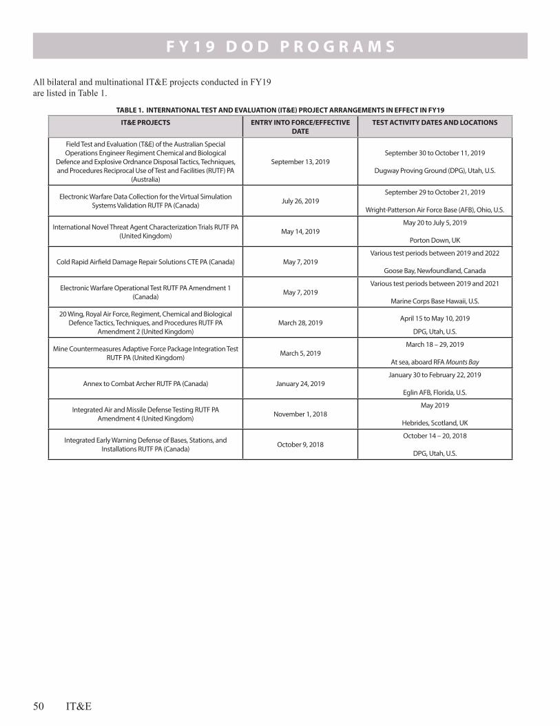
F Y 1 9 D O D P R O G R A M S
50 IT&E
IT&E PROJECTS ENTRY INTO FORCE/EFFECTIVE DATE
TEST ACTIVITY DATES AND LOCATIONS
Field Test and Evaluation (T&E) of the Australian Special Operations Engineer Regiment Chemical and Biological
Defence and Explosive Ordnance Disposal Tactics, Techniques, and Procedures Reciprocal Use of Test and Facilities (RUTF) PA
(Australia)
September 13, 2019September 30 to October 11, 2019
Dugway Proving Ground (DPG), Utah, U.S.
Electronic Warfare Data Collection for the Virtual Simulation Systems Validation RUTF PA (Canada) July 26, 2019
September 29 to October 21, 2019
Wright-Patterson Air Force Base (AFB), Ohio, U.S.
International Novel Threat Agent Characterization Trials RUTF PA (United Kingdom) May 14, 2019
May 20 to July 5, 2019
Porton Down, UK
Cold Rapid Airfield Damage Repair Solutions CTE PA (Canada) May 7, 2019Various test periods between 2019 and 2022
Goose Bay, Newfoundland, Canada
Electronic Warfare Operational Test RUTF PA Amendment 1 (Canada) May 7, 2019
Various test periods between 2019 and 2021
Marine Corps Base Hawaii, U.S.
20 Wing, Royal Air Force, Regiment, Chemical and Biological Defence Tactics, Techniques, and Procedures RUTF PA
Amendment 2 (United Kingdom)March 28, 2019 April 15 to May 10, 2019
DPG, Utah, U.S.
Mine Countermeasures Adaptive Force Package Integration Test RUTF PA (United Kingdom) March 5, 2019
March 18 – 29, 2019
At sea, aboard RFA Mounts Bay
Annex to Combat Archer RUTF PA (Canada) January 24, 2019January 30 to February 22, 2019
Eglin AFB, Florida, U.S.
Integrated Air and Missile Defense Testing RUTF PA Amendment 4 (United Kingdom) November 1, 2018
May 2019
Hebrides, Scotland, UK
Integrated Early Warning Defense of Bases, Stations, and Installations RUTF PA (Canada) October 9, 2018
October 14 – 20, 2018
DPG, Utah, U.S.
TABLE 1. INTERNATIONAL TEST AND EVALUATION (IT&E) PROJECT ARRANGEMENTS IN EFFECT IN FY19
All bilateral and multinational IT&E projects conducted in FY19 are listed in Table 1.

Army Program
s

Arm
y Pro
gram
s

F Y 1 9 A R M Y P R O G R A M S
Army Network Modernization 51
• Interoperability – This effort includes joint interoperability and coalition accessibility through a network that enables appropriate collaboration with all unified action partners.
• Command Posts – The Army wants to improve the mobility and signature (visual, acoustic, thermal, and electromagnetic) of expeditionary command posts.
Network Cross-Functional Team (N-CFT)The N-CFT is working on several lines of effort in order to continue the Army’s network modernization strategy. The N-CFT is developing requirements and systems to create a unified network for the Army to use. This includes efforts to develop and implement an architecture that will unify the tactical network; finding, developing, and demonstrating technologies to create this network; and the creation of requirements. The N-CFT defined a working term, the Integrated Tactical Network (ITN). The ITN is the suite of communications and networking hardware and software that provides voice and data communication capabilities to tactical units. It is the infrastructure necessary to support the current and future voice and data needs (namely mission command software). The N-CFT conducted ITN experiments as a part of Network Integration Evaluation (NIE) 18.2. The NIE 18.2 provided an opportunity to observe the use of the ITN by a battalion (-) under operationally realistic conditions that included cyber and electronic warfare threats. The Army Test and Evaluation Command (ATEC) led a team that observed
Network ModernizationThe 2018 National Defense Authorization Act directed the Army to submit to the congressional defense committees a report on the Army strategy for “modernizing air-land ad-hoc, mobile tactical communications and data networks.” The Chief of Staff of the Army developed a strategy intended to enable the Army to “fight tonight” while seeking technical solutions in order to modernize the Army’s communications. The Army’s strategy recognized that its network had not evolved to enable decisive action against a peer threat in a highly mobile and contested environment. To correct this, the Army seeks to pivot away from traditional acquisition by including non-developmental items and commercial off-the-shelf technologies with programs of record to build its tactical network.The Army strategy created a process by which it experiments and learns about a broad array of technologies. The Army created the Network Cross-Functional Team (N-CFT) to augment traditional acquisition through rapid prototyping and experimentation. The N-CFT is a subordinate organization to the Army Futures Command, combining people, responsibilities, and funding from the requirements, research and development, and systems analysis communities. The N-CFT experimentation informs requirements and design for future acquisition programs. The Army has identified four primary lines of effort to modernize its tactical network:• Unified Network – This effort has three components:
integrated tactical network, integrated enterprise network, and unified network-enabling capabilities. It includes the development of a standards-based network architecture that unifies enterprise and deployed network capabilities and features a unified transport layer, network operations, and other enabling functions that allow integration of disparate networks. A unified network could provide resiliency through path diversity and dynamic routing to ensure tactical units can communicate in hostile environments. A unified network is achievable as allied partners have successfully implemented a similar approach.
• Common Operating Environment (COE) – When complete, the Army intends for the COE to include a set of computing technologies, integrated data and databases, common graphics, and a unified set of mission command applications. It will rely on data standards and virtualization to provide browser-based access to mission command capabilities for at-the-halt and on-the-move leaders.
Army Network Modernization

F Y 1 9 A R M Y P R O G R A M S
52 Army Network Modernization
the 2018 Army Network Modernization Strategy by including a more detailed description of the four lines of effort that compose the network strategy, specific ties to operational needs, and alignment of funding details. The Army initiated a Capability Set acquisition and fielding model to modernize the network over time. Starting with Capability Set 21, the Army has a goal to modernize components within the four lines of effort to make the network more expeditionary and intuitive. Capability Set 21 includes existing fielded systems (i.e. Warfighter Information Network – Tactical), programs beginning full-rate production (i.e. Manpack and Leader Radio), and the MTA rapid prototyping systems. The MTA rapid prototyping effort will transition to a rapid fielding or program of record. The focus of Capability Set 21 is Infantry Brigade Combat Teams. The Army intends to field a new capability set every 2 years. The Army submitted the ITN test and evaluation strategy to Congress in September 2019. The test and evaluation strategy supports the ITN rapid prototyping MTA program and the fielding decision for Capability Set 21. The capstone event of the test and evaluation strategy is a Soldier Touch Point with an infantry battalion during a field training exercise. DOT&E is engaged with the N-CFT and ATEC to develop a plan to collect the data required to support the development of the ITN requirements and the decision to field Capability Set 21. Follow-on strategies will be required for capability sets for FY23 and beyond.
the NIE and published a Capabilities and Limitations Report in January 2019. ATEC recommended continued development of power management options, and improvements in end-user device functionality, training, and troubleshooting. The report recommended that future testing of the ITN should include iterative cybersecurity and electronic warfare testing to find and fix deficiencies.The Army Futures Command approved the ITN Modernization Abbreviated – Capability Development Document on May 31, 2019. This requirements document does not rigidly define the network in order to enable it to evolve over time as the Army identifies new technologies. The Army Acquisition Executive approved a rapid prototyping middle tier of acquisition (MTA) Acquisition Decision Memorandum in May 2019.
Army Network StrategyThe 2019 Senate Appropriations Report 115-290 directed the Army to submit to the congressional defense committees a “network acquisition roadmap” that addressed six objectives, a “test and evaluation plan,” and a notification of “completion of cyber and vulnerability test and evaluation of the enabling [secure but unclassified] capabilities.” The Senate Report required this of the Army prior to fielding any additional secure but unclassified systems to operational units after FY19. The Under Secretary of the Army submitted the Army Tactical Network Acquisition Strategy Roadmap on March 1, 2019, that detailed the acquisition roadmap. This document expanded upon

F Y 1 9 A R M Y P R O G R A M S
Abrams 53
FOT&E plans as a result of positive performance during Production Prove-out Test events and programmatic changes. DOT&E approved the updated TEMP on December 28, 2018.
Activity• The Army conducted operational and live fire testing in
accordance with DOT&E-approved test plans. • The Army updated the Abrams M1A2 SEPv3 TEMP in
FY19. The TEMP update includes revisions to the PQT and
- Power generation and distribution to support the power demands of future technologies
- Compatibility with joint battle command network- Survivability enhancements including Next Evolution
Armor and reduction in vulnerability to IED threats - Reduction in vulnerability to remote-controlled IEDs- Improved lethality by providing the ability for the fire
control system to digitally communicate with the new large caliber ammunition through use of an ammunition datalink
- Energy efficiency (sustainment) due to the incorporation of an auxiliary power unit
- Improved silent watch capability
Mission• Commanders employ units equipped with the M1A2 SEP
MBT to close with and destroy the enemy by fire and maneuver across the full range of military operations.
• The Army intends the M1A2 SEP MBT to defeat and/or suppress enemy tanks, reconnaissance vehicles, infantry fighting vehicles, armored personnel carriers, anti-tank guns, guided missile launchers (ground- and vehicle-mounted), bunkers, dismounted infantry, and helicopters.
Major Contractor General Dynamics Land Systems – Sterling Heights, Michigan
Executive Summary• DOT&E approved an updated Abrams M1A2 System
Enhancement Program (SEP) version 3 (v3) Test and Evaluation Master Plan (TEMP) on December 28, 2018. The updated TEMP included revisions to planned Production Qualification Test (PQT) events and the FOT&E scope.
• The Army conducted the Abrams M1A2 SEPv3 FOT&E at Fort Hood, Texas, April 22 through May 11, 2019.
• In FY19, the Army concluded the M1A2 SEPv3 full-up system-level (FUSL) live fire testing. To complete the survivability assessment of the M1A2 SEPv3, the Army needs to execute the remaining live fire test series focused on addressing combat-induced vulnerabilities of stored ammunition and the modeling and simulation (M&S) effort focused on characterizing armor effectiveness across the operational envelope. The Army expects to complete the M1A2 SEPv3 LFT&E program in 1QFY20.
• DOT&E plans to publish an operational and live fire test report in 2QFY20 to support the program’s scheduled materiel release decision in 3QFY20.
System• The Abrams M1A2 Main Battle Tank (MBT) is a tracked,
land combat, assault weapon system equipped with a 120-mm main gun designed to have significant survivability, shoot-on-the-move firepower, and joint interoperability (for the exchange of tactical and support information). The Abrams MBT possesses a high degree of maneuverability with the ability to respond to hostile entities on the battlefield by engaging or avoiding them before they become a threat.
• The M1A2 SEPv2 is currently fielded. It upgrades the M1A2 by providing increased memory and processor speeds; full color tactical display; digital map capability; compatibility with the Army Technical Architecture; improved target detection, recognition, and identification through incorporation of second-generation Forward-Looking Infrared technology and electronics; Common Remotely Operated Weapon Station (CROWS)-Low Profile (LP); and crew compartment cooling through the addition of a thermal management system.
• M1A2 SEPv3 fielding is planned for FY20. The M1A2 SEPv3 is an upgrade to the M1A2 SEPv2. The upgrades include:
Abrams M1A2 System Enhancement Program (SEP) Main Battle Tank (MBT)

F Y 1 9 A R M Y P R O G R A M S
54 Abrams
• The Army conducted the Abrams M1A2 SEPv3 FOT&E at Fort Hood, Texas, April 22 through May 11, 2019. The test unit consisted of Armored elements from the 1st Brigade, 1st Cavalry Division. The test included offensive and defensive tactical scenarios conducted over three 24-hour periods. The Army conducted a cybersecurity Adversarial Assessment.
• The Abrams M1A2 SEP v3 PQT started in 4QFY18 and is ongoing.
• In FY19, the Army completed FUSL testing to assess the survivability of a combat-ready tank against IEDs, mines, and direct- and indirect-fire. The FUSL test series included 20 tests on 3 production-representative tanks.
• Ammunition Compartment testing began in 4QFY19 and will complete in 1QFY20. These tests examine threats that perforate the tank armor and strike the ammunition compartment to assess the reaction of the stowed ammunition, and any resulting impacts to the crew.
• The Abrams M1A2 SEPv3 survivability evaluation across operational engagement conditions will depend on live fire test data and M&S data. The Army is working on the validation and verification of the M&S tools critical to this evaluation.
• DOT&E plans to publish an operational and live fire test report in 2QFY20 to support the program’s scheduled materiel release decision in 3QFY20.
Assessment• The Abrams M1A2 SEPv3 does not have a unique
requirements document to specify expected survivability and force protection capabilities. The M1A2 Operational Requirements Document from 1994 is the overarching requirements document the Army uses for all M1A2 variants.
• DOT&E continues to collect and assess available live fire test data to characterize the protection provided by the M1A2 SEPv3 against expected operational threats. DOT&E will use M&S to support the final assessment, if the Army demonstrates the credibility of the pertinent M&S tools.
RecommendationsThe Army should:
1. Ensure future Abrams tank upgrades are supported by a comprehensive set of requirements that accurately reflect the current and future operational challenges.
2. Complete the planned validation and verification activities of the pertinent survivability models in accordance with the DOT&E-approved plans.
3. Consider the findings of the DOT&E and Army LFT&E SEPv3 evaluation reports to enhance the survivability of future Abrams tank upgrades

F Y 1 9 A R M Y P R O G R A M S
APS 55
has integrated the Trophy system into the tank’s situational awareness system.
Iron Fist – Light Decoupled APS• The Iron Fist – Light Decoupled APS includes radars and
optics to detect, identify, and track incoming threats, and a set of explosive projectiles intended to destroy or divert the threat. The system adds approximately 1,543 pounds to the platform. The fielded Bradley A3 does not generate sufficient power to operate the APS, while the Bradley A4 power components, currently under development, can support this APS solution.
Stryker APS• The Army evaluated three different solutions for Stryker APS:
Iron Curtain, Advanced Modular Armor Protection – Active Defense System, and the Trophy Medium Variant system. Each vendor had unique technical solutions with different countermeasure mechanisms. The Army did not select any of the three systems evaluated.
Mission• Army and Marine units intend to use Trophy APS-equipped
Abrams main battle tanks to disrupt/destroy certain classes of enemy fire while safely maneuvering across the full range of military operations.
• Army units intend to use Bradley vehicles equipped with the Iron Fist APS to provide protected transport of soldiers, to provide over-watching fires to support dismounted infantry and suppress an enemy, and to disrupt/destroy enemy military forces and control land areas.
• Army commanders intend to use Stryker vehicles equipped with APS (if a suitable solution is found) to disrupt/destroy enemy military forces, to control land areas including populations and resources, and to conduct combat operations to protect U.S. national interests while increasing protection to the vehicle and its crew.
Major Contractors• DRS/Rafael – St. Louis, Missouri • GD-OTS/Elbit Land Systems Ramat Hasharon – Haifa, Israel • UBT/Rheinmettal – Troy, Michigan• Artis – Herndon, Virginia
Executive Summary • In FY17, in support of the European Deterrence Initiative, the
Army initiated an expedited installation and characterization of three Active Protection Systems (APS): the Rafael Trophy APS for the Army Abrams M1A2 and Marine Corps M1A1 tanks, the Artis Iron Curtain APS for the Stryker family of vehicles, and the Elbit Iron Fist – Light Decoupled APS for the Bradley family of vehicles.
• The selected APS technologies are non-developmental items intended to improve the survivability of ground combat vehicles against anti-tank guided missiles, rocket-propelled grenades (RPGs), and recoilless rifle threats by using a kinetic “hard kill” mechanism to intercept and disrupt/defeat the incoming threat.
• The Army tested the APS in two phases. Phase I assessed technology maturity, performance, and integration. Phase II supported the urgent materiel release (UMR).Trophy APS • In FY19, the Army completed Phase II of the Trophy
APS testing. DOT&E will summarize the demonstrated performance in a combined OT&E/LFT&E report in 2QFY20 to support the UMR.
• Based on the demonstrated performance, the Army issued a directed requirement to procure and install Trophy APS systems on Abrams for a total of four Armored Brigade Combat Teams, by the end of FY20.
Iron Fist – Light Decoupled APS• In FY18, the Army completed Phase I Iron Fist APS testing
on the Bradley. This test supported the Army Requirements Oversight Council (AROC) meeting on November 30, 2018, where the Army decided to move forward with the Phase II Iron Fist – Light Decoupled APS program. Phase II testing is currently scheduled for FY21.
Stryker APS• In FY18, the Army completed Phase I Iron Curtain APS
testing on the Stryker. In FY19, the Army pursued and tested two additional Stryker APS solutions: Advanced Modular Armor Protection – Active Defense System by UBT/Rheinmetall and the Trophy Light system by DRS/Rafael. The Army has not selected any of these solutions due to the demonstrated performance and the systems maturity.
SystemTrophy APS• The Trophy APS includes search radars to detect,
identify, and track incoming threats, and a set of kinetic projectiles intended to destroy the threat or cause its early detonation. The Abrams base armor is expected to absorb post-engagement threat residuals (threat by-products generated after the collision). The Trophy APS adds approximately 8,600 pounds to the platform. The Army
Active Protection Systems (APS) Program
F Y 1 9 A R M Y P R O G R A M S
56 APS
Activity• The Army used a two-phased approach to characterize the
performance of the APS solutions in support of the UMR: - Phase I consisted of limited characterization testing intended
to determine fundamental capabilities and limitations of the APS and feasibility of installing APS systems on the host platforms.
- Phase II focused on testing production-representative APS as installed on operationally representative systems under realistic combat conditions.
Trophy APS • In September 2017, the Army completed Phase I testing.
Phase I testing also included 10 Marine Corps Abrams tests with moving vehicle and inert threats.
• In September 2019, the Army completed Phase II testing, which included: - Operational testing at Fort Bliss, Texas, from November
28 through December 14, 2018. An armored platoon outfitted with Trophy APS-equipped M1A2 SEPv2 tanks successfully conducted maneuver and gunnery test events. The test unit completed Trophy APS familiarization training, a force-on-force maneuver event against an opposing force, and tank qualification gunnery. The final test event consisted of four effectiveness shots utilizing inert RPG threats to assess how well Trophy APS retained system calibration following maneuver and gunnery.
- The Army and Marine Corps completed 62 live fire tests including some operationally stressing conditions (e.g., background clutter, rain, concrete walls) to adequately evaluate the APS performance. Live fire testing included inert unguided threats fired against either a fully functional Abrams SEPv2 or Marine M1A1 tanks equipped with Trophy, and live rocket and missile threats fired against a ballistic hull and turret tank shell powered by a generator.
- The Army completed one live fire test against a fully functional Abrams SEPv2 tank to assess a potential for cascading, system-level damage effects post intercept.
- The Army conducted Trophy APS Phase II testing at Redstone Test Center, Aberdeen Test Center, Yuma Test Center, and Fort Bliss in accordance with DOT&E-approved test plans.
• The Army is planning a Phase III test series to examine Trophy APS as installed on Abrams SEPv3 vehicles.
Iron Fist – Light Decoupled APS • In August 2018, the Army completed Phase I testing, which
included live fire and user excursion tests. The contractor (Elbit) conducted follow-on testing in Israel to implement and retest changes to the system design needed for the AROC decision to enter Phase II. Phase II planning will be conducted in FY20.
Stryker APS • From December 2018 to April 2019, the Army tested two
alternate APS solutions intended to characterize the maturity and feasibility of these systems as installed on a Stryker vehicle.
AssessmentTrophy APS • During Phase I, Trophy APS countered most of the threats
tested in basic range conditions and threat engagements. The Army relied heavily on the contractors to set up the Trophy APS due to the limited knowledge of the foreign system.
• The evaluation of Phase II live fire testing is ongoing. The Army trained the test personnel to use the system without help from the contractor. The Army is maturing the existing vulnerability modeling and simulation tools to complement the system assessment.
• The evaluation of Phase II operational testing is ongoing. Limited testing was conducted to assess installation time, transportation issues, and technical manual validation. There was no real-time casualty assessment (RTCA) or simulator support for Trophy APS testing. This hindered the test unit’s ability to develop or assess crew and platoon tactics, techniques, and procedures associated with Trophy APS employment in a force-on-force environment. The Army has no plans to develop RTCA. The Army is developing Training Aids, Devices, Simulators, and Simulations for Trophy APS.
• Phase II live fire and operational testing was designed to support the fielding of one brigade of pre-positioned stocks to the European Command.
• DOT&E will detail the performance of the Trophy APS-equipped Abrams tank in a combined OT&E/LFT&E report in 2QFY20 to support the UMR.
Iron Fist – Light Decoupled APS • Phase I demonstrated an inconsistent capability of the Iron
Fist APS to intercept threats largely due to countermunition dudding and power failures to the launcher. The Army has been working with the vendor to address and implement some prospective solutions to mitigate these shortfalls. The Army will verify these fixes in Phase II scheduled for 1QFY21. A demo of the Phase II system will be conducted at the vendor’s test facility in December 2019.
Stryker APS • Testing showed neither system was immediately suitable
for Stryker. Currently, the Army has not selected any of the tested solutions due to system maturity.
RecommendationsThe Army should:
1. Ensure Trophy Phase III testing is designed to examine areas identified as a concern in Phase II.
2. Continue to develop and advance the appropriate modeling and simulation tools needed to support the test planning and evaluation of systems equipped with APS.
3. Include test events designed to assess logistical considerations for maintenance and countermunition resupply.
4. Conduct additional testing to further assess installation and transportability considerations.

F Y 1 9 A R M Y P R O G R A M S
AH-64E 57
Correlation Engine to merge icons, and the Fire Detection and Expansion System to improve survivability in the event of an onboard fire.
• The Army intends Version 6 to improve and expand the capabilities of the FCR by adding a maritime capability and expanding ranges of existing capabilities, updates to an MRFI to provide passive detection and geolocation of emitting radar threats, and expanding unmanned capabilities with the MUMT – eXpanded (MUMT-X), which increases interoperability control of unmanned platforms and improves Link-16 functionality.
MissionThe Joint Force Commander and Ground Maneuver Commander employ AH-64E-equipped units to shape the area of operations and defeat the enemy at a specified place and time. The Attack Reconnaissance Battalions assigned to the Combat Aviation Brigade employ the AH-64E to conduct the following types of missions: • Attack• Movement to contact • Reconnaissance• Security
Major Contractors• Aircraft: The Boeing Company Integrated Defense Systems –
Mesa, Arizona• Targeting Sensors and Unmanned Aircraft System datalink:
- Longbow Limited Liability Company – Orlando, Florida, and Baltimore, Maryland
- Lockheed Martin Corporation – Orlando, Florida, and Owego, New York
• L3 Communications Systems – Salt Lake City, Utah
Executive Summary• The Army completed FOT&E II of the Version 6 AH-64E in
3QFY19. FOT&E II included training, realistic comparative force-on-force tactical scenarios with Version 4 AH-64E aircraft, live ordnance firing, and adversarial cybersecurity testing.
• The Version 6 includes numerous enhancements that improves the lethality, operational effectiveness, and survivability of the AH-64E.
• The Modernized Day Sensor Assembly (MDSA) increases the range at which aircrews can positively identify targets during daytime conditions allowing for greater standoff engagement ranges. The Modernized Radar Frequency Interferometer (MRFI) provides passive geolocation of emitting radar threats. The addition of a maritime mode and extended range of existing modes on the Fire Control Radar (FCR) expands engagement opportunities.
• Manned-Unmanned Teaming (MUMT) effectiveness for Version 4 and Version 6 units was limited during FOT&E II. Aircraft interfaces, employment concepts, procedures, and documentation are not mature and contributed to the lack of interoperability between AH-64E aircraft and unmanned aircraft systems.
• The Version 6 Adversarial Assessment (AA) revealed no critical vulnerabilities that would immediately lead to the degradation of the aircraft’s confidentiality, availability, or integrity from an insider or nearsider threat posture.
• The Army completed joint live fire testing of the fire detection and expansion system, demonstrating an increase in force protection in the case of tail boom fires.
System• The AH-64 Apache Attack Helicopter is a tandem cockpit,
four-bladed, twin-engine helicopter that operates in all tactical environments. The aircraft type was first fielded as the AH-64A in 1986 and has undergone two major modernizations: AH-64D in 1997 and AH-64E in 2012.
• The Version 6 AH-64E is the final planned modernization of the AH-64D. The Army will continue the AH-64D modernization program, which remanufactures aircraft into the Version 6. It will institute a retrofit program to update all earlier versions of the AH-64E to the Version 6. The Apache will sustain the Army’s Attack Helicopter fleet through 2050.
• The Army uses the AH-64E in Attack Reconnaissance Battalions assigned to Combat Aviation Brigades. Each battalion has 24 aircraft. The current Army procurement objective is 791 aircraft.
• The Version 6 adds the MDSA to the Modernized Target Acquisition Designation Sight, integration of the Joint Air-to-Ground Missile (JAGM), the Cognitive Decision Aiding System to improve pilot situational awareness, a Data
AH-64E Apache

F Y 1 9 A R M Y P R O G R A M S
58 AH-64E
Activity• The Army completed all testing in accordance with a
DOT&E-approved Test and Evaluation Master Plan, operational and live fire test plans, and Live Fire Strategy.
• Developmental testing of Version 6 software and major subsystems in 2018 revealed multiple performance deficiencies. One or more deficiencies affected the Multi-Core Mission Processor, Modernized Radar Interferometer, the Fire Control Radar, the Target Acquisition Designation Sight, and MUMT. The discovery of these problems resulted in postponement of the planned Version 6 FOT&E until FY19. DOT&E supported the Army decision to fix problems discovered and delay FOT&E II.
• In 2019, the Army conducted development and regression testing of subsystems to verify that fixes to the problems discovered in FY18 had been corrected. This testing verified the functionality of the pilot vehicle interface for employment of the JAGM missile.
• Apache aircraft supported integrated testing of 70 JAGM missiles using Version 4.5 and Version 6 Apache software.
• The Army conducted a Cooperative Vulnerability and Penetration Assessment in September 2017 and conducted an AA of the Version 6 in June 2019.
• The Army completed FOT&E II for the Version 6 in 3QFY19. FOT&E II included training, realistic comparative force-on-force tactical scenarios with the Version 4 aircraft, live ordnance firing, and adversarial cybersecurity testing.
• In August 2018 and May 2019, the Army Research, Development and Engineering Command/Survivability/Lethality Analysis (RDECOM/SLAD) performed Joint Live Fire-funded tests under operationally representative flight loading to assess the effectiveness of a fire barrier and fire-resistant intumescent paint previously added to production AH-64s to minimize fire-induced damage effects.
• Testing of the onboard engine nacelle halon fire suppression system is delayed and is now expected to begin in 2QFY20.
Assessment• Version 6 have improved operational effectiveness compared
to the units equipped with Version 4. Version 6 units had higher mission success scores and engaged targets at greater ranges than Version 4 units.
• The JAGM employment timeline was comparable to that of HELLFIRE missiles and provides increased capability against countermeasures and targets at longer ranges.
• The Version 6 Adversarial Assessment conducted in 3QFY19 revealed no critical vulnerabilities that would immediately lead to the degradation of aircraft confidentiality, availability, or integrity from an insider or nearsider threat posture.
• New Link 16 functionality reduced target acquisition timelines for threat radars and helped coordinate engagements among Apache aircrews. The FCR added maritime engagement modes and increased target ranges for existing modes.
• While most of the enhancements worked as the Service anticipated, improvements to MUMT-X could not be demonstrated in an operational environment. When connectivity could be established, interoperability showed no improvement over that of the MUMT-2 found on legacy AH-64D/E platforms.
• MUMT effectiveness for Version 4 and Version 6 units was limited during FOT&E. Interoperability and video sharing between AH-64E Apaches, unmanned aircraft systems, and ground stations is complicated and requires exacting pre-mission coordination of technical information across multiple organizations and systems. Aircraft interfaces, employment concepts, procedures, and documentation are not mature and contributed to the lack of interoperability between AH-64E aircraft and unmanned aircraft systems.
• Version 6 aircraft have improved operational suitability compared to Version 4. Pilots report that the Version 6 is easier to use and has lower workload than the Version 4. Version 6 aircraft are as reliable, available, and maintainable as Version 4 aircraft and achieved reliability requirements with statistical confidence.
• Version 6 units were more survivable than Version 4 units during FOT&E II. MRFI provided automatic, passive detection of radar threat locations. MDSA assisted in pinpointing threat emitter locations to enable Version 6 units to find and engage threat radars at a rate 4.5 times higher than Version 4 units. Lacking a similar level of threat awareness, Version 4 units maneuvered cautiously through the objective area, taking care to remain below line-of-sight, but often failing to find and defeat threat radars during the mission.
• Joint Live Fire testing of the loaded tail boom with fire barrier and intumescent paint demonstrated a 2.5 minute increase in the time before the structure degraded and the tail boom failed. Version 6 with the fire detection and expansion system provides improved force protection over legacy Apache aircraft without these modifications.
Recommendation1. The Army should improve interoperability with unmanned
aircraft systems, simplify pilot vehicle interfaces, and improve training documentation for MUMT.

F Y 1 9 A R M Y P R O G R A M S
AMPV 59
• The AMPV has five variants:- GP vehicle from which the unit First Sergeant conducts
combat resupply escort, emergency resupply, and casualty evacuation; and provides security for medical evacuation.
- Mission Command vehicle to integrate the communications equipment in accordance with the Network Systems Architecture.
- Medical Treatment (MT) vehicle to provide an armored and mobile protected environment for the unit surgeon and medical staff to provide immediate medical care of casualties or life stabilization triage for casualties prior to their evacuation to more capable facilities.
- Medical Evacuation (ME) (Ambulance) vehicle supports the ABCT integration of medical support providing protected ambulance evacuation and immediate medical care to the mechanized and armored cavalry units.
Executive Summary• Upon completion
of a Limited User Test (LUT) in September 2018, the Army approved Milestone C and the Armored Multi-Purpose Vehicle (AMPV) program entered into low-rate initial production (LRIP).
• The Program Office identified several engineering and design fixes to address the deficiencies identified during the LUT.
• Production delays and quality challenges from the BAE plant in York, Pennsylvania, affect the test schedule and may cause a delay of the IOT&E scheduled for 3QFY21.
• In FY19, the Army completed Phase I system-level live fire testing of the AMPV General Purpose (GP) and Mortar Carrier (MC) variants to assess survivability and force protection specification requirements. Live fire testing will continue through 3QFY21 for all AMPV variants.
System• The AMPV will replace the M113 Family of Vehicles program
that the Army terminated in 2007. The AMPV is required to operate alongside the M1 Abrams Main Battle Tank and the M2 Bradley Infantry Fighting Vehicle in the Armored Brigade Combat Team (ABCT).
• The Army intends for the AMPV variants to address the M113 shortcomings in survivability and force protection; size, weight, power, and cooling; and the ability to incorporate future technologies, such as the Army Network.
• The Army is reusing the Mission Equipment Packages from the existing M113 FoV in the AMPV variants.
Armored Multi-Purpose Vehicle (AMPV)

F Y 1 9 A R M Y P R O G R A M S
60 AMPV
- MC vehicle provides immediate, responsive, heavy mortar fire support to the ABCT in the conduct of fast-paced offensive operations by utilizing the M121 Mortar System and the M95 Mortar Fire Control System.
MissionCommanders employ units equipped with the AMPV to provide a more survivable and highly mobile platform to accomplish
required operational support missions across the range of military operations. ABCT units use AMPVs to conduct logistical resupply; casualty evacuation and treatment; command post operations; and heavy mortar fire support.
Major ContractorBAE Systems – York, Pennsylvania
Activity• DOT&E provided emerging results of AMPV LUT
performance to the program manager in October 2018. • The program manager requested permission to enter into LRIP
at Milestone C from the Assistant Secretary of the Army for Acquisition, Logistics and Technology in October 2018.
• DOT&E approved the Milestone C Test and Evaluation Master Plan in December 2018.
• The program entered into LRIP in January 2019, with the first LRIP vehicle expected delivery in March 2020.
• DOT&E published the final Operational Assessment and Live Fire survivability evaluation of the AMPV in June 2019.
• The Program Office expects the BAE delivery of first LRIP vehicles to be delayed by 2 months and the completion of production qualification testing (PQT) to be delayed by 7 months due to BAE-York tooling and the assembly line challenges.
• In September 2019, the Program Office presented an updated engineering plan to address the major deficiencies identified by both the DOT&E and Army Test and Evaluation Command (ATEC) reports. Fourteen of the deficiencies are to be addressed during the redesign of the vehicle and corrected prior to the first vehicle completing LRIP. Seven of the deficiencies are to be corrected after LRIP has begun, but corrected prior to the start of the IOT&E in 3QFY21.
• The Program Office and BAE have begun instituting the following design and engineering changes to address the deficiencies observed by DOT&E and ATEC. - BAE is updating assembly and manufacturing instructions
for shimming and sealing all hatches to correct leaking at all of the hatch seals.
- BAE is installing a low battery Warning Caution Alert and updated harness design to remove stresses on connectors, and updated voltage regulator to prevent voltage regulator failures. This is intended to address the frequent rebooting of the electronics and frequent blacking out of the screens.
- The U.S. Army Armament Research, Development and Engineering Center is developing a Commander’s Weapon Station with larger hatch space and improved positioning of ballistic glass to improve both the ability to reload mounted weapons and the vision and situational awareness around the vehicle.
- The Program Office is considering the installation of a 25-foot cable with a monitor to allow a unit to project the
Joint Battle Command Platform display into the Tactical Operations Center from the interior of the vehicle.
- The Program Office is developing a map board and installation kit to facilitate analog operations.
- BAE redesigned the ambulatory patient seats to improve ambulatory to litter configuration for easier and faster operation.
- BAE moved the antenna bracket on the MC 6 inches to reduce probability of antenna damage due to blast overpressure during mortar firing.
- BAE has updated the ramp cable design to incorporate a cable tray to route the wiring harnesses away from stowed ammunition in order to eliminate interference of the ramp cable with the stowed mortar ammunition.
- BAE welded a new base to the bipod to prevent the latch from disengaging during firing. ATEC conducted a successful prove out test and an additional durability test to verify the design.
• The June 2019 report included results from live fire testing performed during the Engineering and Manufacturing Development phase (e.g., armor coupon testing, ballistic hull testing, and some Phase I system-level testing).
• The Army continues to conduct live fire testing in accordance with DOT&E-approved test plans.
• The Army completed Phase I system-level live fire tests in September 2019 on prototype GP and MC variants to evaluate system and crew vulnerability to direct-fire kinetic energy munitions, shape-charged jet threats, artillery, explosively formed penetrators, and side and underbody mines.
• Phase II system-level live fire tests will begin in 4QFY19 and end in 3QFY20. The Phase II live fire test series includes eight underbody events distributed across all AMPV variants with the exception of the MC variant that was tested during Phase I.
• AMPV full-up system-level (FUSL) testing is on schedule to start in FY20. Informed by Phase I and Phase II live fire test data, the Army efficiently designed the FUSL test series to support a system survivability and crew casualty assessment of the production-representative AMPV variants against expected operational threats.

F Y 1 9 A R M Y P R O G R A M S
AMPV 61
Assessment• Delay in delivery of vehicles will have a significant effect on
the remaining test schedule. The program manager assesses the IOT&E may be delayed by 4 months.
• During the LUT, full understanding of the cybersecurity vulnerabilities could not be assessed because of the lack of an outsider threat environment.
• The corrective actions taken to address deficiencies in the vehicle will be assessed during PQT and the IOT&E.
• The LFT&E program conducted during the Engineering and Manufacturing Development phase identified minor vehicle design vulnerabilities that the Program Office is addressing with the vendor to meet survivability and force protection requirements.
• Preliminary analysis of armor coupon testing demonstrated expected armor protection capabilities.
• DOT&E will provide a comprehensive classified AMPV survivability LFT&E report to support the Full-Rate Production decision in FY22.
RecommendationsThe Army should:
1. Verify the corrective measures derived from the deficiencies identified during the LUT during PQT and IOT&E.
2. Continue to correct and validate design changes intended to mitigate vehicle and crew vulnerabilities found in live fire testing.
3. Conduct the IOT&E in an operational environment where full cybersecurity testing can be exploited.

62
F Y 1 9 A R M Y P R O G R A M S

F Y 1 9 A R M Y P R O G R A M S
AIAMD 63
• In August 2019, the Army executed Missile Flight Test 4 at White Sands Missile Range (WSMR), New Mexico, with two Sentinel radars, one Patriot radar, and one Patriot launcher on the IFCN.- Operators used the networked Sentinel radars to detect
the target and create a composite track for a cruise missile surrogate at a distance beyond the Patriot radar coverage.
Activity• In April 2019, the Army started DT of new IBCS software,
version 4.5, in accordance with the DOT&E-approved Test and Evaluation Master Plan.
• The Army has begun qualification testing of redesigned AIAMD hardware. The testing includes transportation, mobility, and electromagnetic environmental effects, as well as multiple environmental conditions in the McKinley Climatic Laboratory at Eglin AFB, Florida.
Mission• Army commanders will use AIAMD to provide timely
detection, identification, monitoring, and (if required) engagement of air threats in an assigned area of responsibility.
• AIAMD will deploy to provide active protection for the following:- Air defense of the homeland- Air defense of priority critical assets and locations- Air defense of forces
Major Contractors• Northrop Grumman – Huntsville, Alabama• Raytheon – Huntsville, Alabama, and Andover, Massachusetts• Lockheed Martin – Dallas, Texas
Executive Summary• In April 2019, the Army started developmental
testing (DT) of the Army Integrated Air and Missile Defense (AIAMD) system and conducted a missile flight test in August 2019.
• In early DT events, the IAMD Battle Command System (IBCS) software version 4.5 demonstrated better stability when compared to version 3.1.1 used in the Limited User Test (LUT) conducted in 2016.
• The August 2019 missile flight test demonstrated the capability for AIAMD to detect, track, and intercept a subscale target at a distance greater than a Patriot system could achieve on its own.
System• AIAMD is a command and control system
that integrates sensors, weapons, and a common mission command interface across an integrated fire control network (IFCN).
• IBCS provides the common IAMD Mission Control capability, integrating Sentinel air surveillance radars, Patriot radars, and Patriot launchers for improved missile employment.
• AIAMD includes the Engagement Operations Center (EOC), hardware interface kits, and IFCN Relays.- EOCs provide the operating environment for all levels
of employment. They are equipped with workstations providing a Common Warfighter-Machine Interface (CWMI) to monitor and direct sensor employment and engagement of air threats.
- The IFCN is the primary communications infrastructure for the AIAMD system to provide fire control connectivity and distributed operations. Hardware interface kits connect Patriot and Sentinel components to the IFCN.
- The IFCN Relay provides a mobile IFCN communications node with an interface kit to extend connectivity to remote launcher and sensor platforms.
Army Integrated Air & Missile Defense (AIAMD)

F Y 1 9 A R M Y P R O G R A M S
64 AIAMD
- The operators used the CWMI to command the launch of a single Patriot Advanced Capability (PAC)-3 Cost Reduction Initiative (CRI) missile, which intercepted the target near the maximum kinematic range of the PAC-3 CRI.
• The Army has improved the data collection and reduction capacity at WSMR and intends to increase the network infrastructure at the Aberdeen Test Center, Maryland, to support analysis for the next LUT.
• In August 2019, the AIAMD Project Office started New Equipment Training for soldiers of the 3rd Battalion, 43rd Air Defense Artillery Regiment at Fort Bliss, Texas. These soldiers will be operators during the LUT planned to begin in April 2020.
• The Army plans to execute Missile Flight Test 5 in December 2019 at WSMR with two Sentinel radars, one Patriot radar, and four Patriot launchers on the IFCN.- Soldiers will use the networked Sentinel and Patriot radars
to acquire and track the targets, and then use the CWMI
to command the launch of a PAC-3 Missile Segment Enhancement interceptor and a Guidance Enhanced Missile Tactical Ballistic Missile (TBM) (GEM-T) interceptor against a TBM surrogate while simultaneously engaging a cruise missile surrogate with another GEM-T interceptor.
Assessment• Missile Flight Test 4 analysis is ongoing. The engagement was
successful, but operators observed off-nominal behavior during launcher emplacement and initialization.
• During early DT events, AIAMD demonstrated improved hardware reliability and software stability when compared to DT events using software version 3.1.1 leading to the 2016 LUT.
Recommendation1. The Army should conduct a pilot test to demonstrate
adequate data collection, reduction, analysis, and delivery prior the start of the LUT planned for 2020.

F Y 1 9 A R M Y P R O G R A M S
Army Tactical Wheeled Vehicles 65
SystemISV• The ISV is the program of record for the Army Ground
Mobility Vehicle. The ISV provides mobility on the battlefield for a nine-soldier light Infantry Squad with their associated equipment. The vehicle has a payload requirement of 3,200 pounds to support the Infantry Squad conducting 72-hour operations.
• The ISV has a maximum vehicle curb weight of 5,000 pounds to meet the requirement for external transport by the UH-60. The vehicle is required to be external and internal transportable by a CH-47 helicopter and airdropped by C-17 and C-130 aircraft.
Executive Summary• In August 2019, the Infantry Squad Vehicle (ISV) program
selected three vendors to participate in prototype testing, based on evaluation of Requests for Prototype Proposals (RPPs) and results of vehicle sample tests.
• The ISV Milestone C decision and down-select to a single contractor is planned for 3QFY20.
• In August 2019, the Army began the DOT&E-approved LFT&E program designed to demonstrate the survivability of the Family of Medium Tactical Vehicles (FMTV) A2 and its occupants against mines and IEDs threats.
• The FMTV program delayed the start of FMTV A2 Production Verification Test (PVT) because the contractor was required to address and fix production design deficiencies.
Army Tactical Wheeled Vehicles

F Y 1 9 A R M Y P R O G R A M S
66 Army Tactical Wheeled Vehicles
FMTV • The FMTV A2 is a set of hardware and software
improvements to the FMTV A1 trucks designed to expand the capabilities of the FMTV. These upgrades include: adjustable suspension system, increased payload, electronic stability control, and an underbody protection kit. The FMTV A2 Family of Vehicles (FoV) consists of the following light and medium variants that operate on- and off-road. - The Light Medium Tactical Vehicle (LMTV) transports a
6,000-pound payload and a 12,000-pound towed load. - The Medium Tactical Vehicle (MTV) transports a
16,000-pound payload and a 21,000-pound towed load.
MissionISV• Infantry Brigade Combat Team commanders employ the
ISV to provide mobility and logistics support capability to conduct engagement, security, deterrence, and decisive-action missions. Airborne and air assault Brigade Combat Teams employ the ISV during austere and offset entry operations to provide rapid cross-country mobility to conduct initial entry and offensive operations.
FMTV• The Army employs the FMTV FoV to provide
multi-purpose transportation in maneuver, maneuver support, and sustainment units. Transportation units conduct line and local haul missions carrying cargo and soldiers with the LMTV and MTV Cargo variants and associated trailers. Medical units employ the MTV – Load Handling System to transport, load, and off-load medical containers. Maintenance units use the MTV wrecker to conduct recovery operations of light- and medium-wheeled vehicles. Engineering units employ the MTV Dump Truck to haul and dump material.
Major ContractorsISV • Oshkosh/Flyer Defense – Oshkosh, Wisconsin• Science Applications International Corp (SAIC)/Polaris
Government and Defense – Reston, Virginia• General Motors Defense – Detroit, MichiganFMTV • Oshkosh Corporation – Oshkosh, Wisconsin
ActivityISV • The ISV program began in 2QFY17. DOT&E placed the
ISV program under oversight for OT&E in June 2017. This is the first annual report for the program.
• In June 2019, the program conducted a Soldier Touchpoint 1 event at Fort Bragg, North Carolina, with five vendors’ ISVs to obtain soldier and crew feedback on design, operations, and ease of ingress/egress. The program used the feedback along with performance data to assess user acceptability of the five vendors’ proposals as part of the ISV Other Transaction Authority RPP.
• In August 2019, the program selected three vendors’ ISVs to participate in prototype testing based on evaluation of RPPs and results of vehicle sample tests. - Oshkosh/Flyer Defense - SAIC/Polaris - General Motors Defense
• The program intends to use prototype developmental testing and a second Soldier Touchpoint event to inform an ISV Production Request for Proposal and Source Selection Board activities to down select to a single contractor ISV in 3QFY20.
• In November 2019, the Army Test and Evaluation Command (ATEC) began ISV prototype developmental testing at Aberdeen Proving Ground, Maryland. The objective of the testing is to demonstrate that the vendors’ ISVs can meet selected Key Performance Parameters and System Attributes.
• The program is developing a Test and Evaluation Master Plan (TEMP) to reflect the test and evaluation activities for a Milestone C decision, production, and deployment phase of the program.
• The Milestone C Low-Rate Production decision is planned for 3QFY20.
FMTV• In FY19, the program began development of an FMTV
A2 TEMP Annex to outline the PVT and FOT&E for the FMTV A2 FoV. The program plans to submit the FMTV A2 TEMP Annex for DOT&E approval in February 2020.
• The program developed a separate LFT&E Strategy for FMTV A2 FOV. DOT&E approved the LFT&E strategy in February 2019.
• In August 2019, the Army began the FMTV A2 LFT&E program consisting of five tests intended to assess the performance of the new underbody kit as a function of mine/IED charge and engagement location.
• In September 2019, ATEC began performance and reliability testing on the FMTV A2 variants to verify compliance to the FMTV A2 performance specification. This testing, at Aberdeen Proving Ground, Maryland, will accumulate 179,000 miles on three FMTV A2 vehicles in both armored and unarmored configurations to assess whether the variants can meet their Mean Miles Between Operational Mission Failures (MMBOMF) requirement.

F Y 1 9 A R M Y P R O G R A M S
Army Tactical Wheeled Vehicles 67
Depending on the FMTV variant, the reliability requirement varies between 5,000 to 6,500 MMBOMF.
• ATEC plans to conduct the FMTV A2 FOT&E in 4QFY21 at Yuma Proving Ground, Arizona.
AssessmentISV• The Soldier Touchpoint 1 provided soldier assessment
of loading mission-essential equipment in the vehicle, suitability of the location of weapons mounts, casualty evacuation, and squads driving the vehicle over a 26-mile trail. The event focused on soldiers completing tasks rather than an ISV-equipped squad accomplishing missions.
• DOT&E recommends the ISV developmental testing and Soldier Touchpoint 2 include reliability testing of the three vendors’ vehicles and demonstrate the ISV capabilities to support small unit mission accomplishment prior to the Milestone C and down-select decision.
FMTV• The FMTV A2 LFT&E program is ongoing and the
preliminary assessment of the first tests demonstrated the expected performance of the underbody kit.
• The program has taken considerable action to require the vendor to fix production design deficiencies with the FMTV suspension and heat exchange systems. These design problems delayed the planned start of PVT by approximately 6 months.
• The program slipped the FOT&E from 1QFY21 to 3QFY21 to ensure the performance and reliability testing and logistics products are completed before the start of the FOT&E.
Recommendation1. The ISV program should perform reliability testing
of vendor’s ISV prior to Milestone C. The Soldier Touchpoint 2 event in January 2020 should include a small unit conducting end-to-end operational missions.

68
F Y 1 9 A R M Y P R O G R A M S

F Y 1 9 A R M Y P R O G R A M S
Bradley 69
vehicles while Phase II will focus on FUSL events using production-representative vehicles. The Army completed Phase I testing in FY19 and is scheduled to complete Phase II testing in FY21.
• Phase I live fire testing, performed from June 2018 to September 2018, included two shaped-charge jet test events, one thermobaric warhead test event, and two IED/mine engagement tests.
Activity • The Army submitted an updated Test and Evaluation Master
Plan with a comprehensive Phase I LFT&E Strategy that DOT&E approved in April 2016 with changes approved in December 2018.
• The Army conducted all FY19 testing in accordance with the DOT&E-approved Test and Evaluation Master Plan and test plan.
• The Bradley ECP LFT&E program consists of two phases. Phase I included system-level tests using prototype
Tiles, and Add-on Armor Kit that the Army developed and fielded in response to Operational Needs Statements during Operation Iraqi Freedom. The A4 will also include the Commander’s Independent Viewer.
MissionCombatant Commanders employ Armor Brigade Combat Teams equipped with Bradley Fighting Vehicles to provide protected transport of soldiers, provide direct fires to support dismounted infantry, to disrupt or destroy enemy military forces, and to control land areas.
Major ContractorBAE Systems Land and Armaments – Sterling Heights, Michigan
Executive Summary• In 2019, the Army completed Phase I live fire testing of the
Bradley Fighting Vehicle Systems (BFVS) Engineering Change Proposal (ECP) to evaluate the effect of these changes on the survivability of the Bradley to combat engagement-induced ballistic shock and underbody accelerative loads.
• Preliminary analysis of Phase I live fire testing did not reveal any significant or unexpected vulnerabilities.
• The Army is on schedule to complete the Phase II Full-Up System-Level (FUSL) live fire test events using a production-representative Bradley vehicle in FY21.
• DOT&E will complete a detailed survivability analysis to support the Bradley A4 Early Fielding Decision in FY21.
System• The Bradley ECP program integrates new technologies to
mitigate the degradation of existing system performance and maintains the operational capability outlined in current system requirements documents.
• ECP Phase I included a suspension and track upgrade to restore ground clearance and suspension reliability because of increases in Bradley armor and weight.
• ECP Phase II will upgrade the electrical system and power train to restore lost mobility, and integrate new technologies to improve situational awareness and vehicle survivability.
• Completion of Phases I and II will result in the conversion of existing M2A3 and Operation Desert Storm – Situational Awareness (ODS-SA) versions of Bradley Fighting Vehicles into the M2A4 version, and the conversion of M7A3 Bradley Fire Support Team vehicle into the M7A4 version. The current plan is to convert four brigades to the A4 variant and supply the European Deterrence Initiative with one brigade set of A4 vehicles.
• The A4 versions will inherit the survivability enhancement features found on the A3/ODS-SA baseline configurations: Bradley Urban Survivability Kits, Bradley Reactive Armor
Bradley Family of Vehicles (BFoV) Engineering Change Proposal (ECP)

F Y 1 9 A R M Y P R O G R A M S
70 Bradley
• Phase I also included Automatic Fire Extinguishing System testing performed from February to May 2019 to evaluate the effectiveness of the system to mitigate combat-induced fires.
Assessment • Preliminary analysis of Phase I live fire testing did not reveal
any significant or unexpected vulnerabilities. • In FY21, after the completion of Phase II live fire test series,
DOT&E will finalize the Bradley A4 survivability assessment
in support of its Early Fielding Decision. The assessment will consider Phase I and Phase II data as well as Bradley Reactive Armor Tiles tests completed in FY16, and modeling and simulation events.
RecommendationsNone.

F Y 1 9 A R M Y P R O G R A M S
Chemical Demilitarization 71
• As of September 2019, the Chemical Demilitarization Program has destroyed over 90 percent of the total U.S. chemical weapons stockpile (originally 31,498 agent tons).
• Operational testing at PCAPP began in FY16 and at BGCAPP in FY19. The Army is conducting operational
Activity • The Chemical Demilitarization Program is not a traditional
acquisition program. DOT&E oversight began in 1999 when Congress directed that the DOD oversee this program as a separate major defense acquisition program due to cost and schedule overruns.
• The Assembled Chemical Weapons Alternatives (ACWA) uses explosive destruction technology for problematic chemical munitions that are not easily processed in the main plant. The two types of systems available for use are the Explosive Destruction System (EDS) and Static Detonation Chamber (SDC).
MissionThe United States is using the Chemical Demilitarization Program to comply with the Chemical Weapons Convention. The United States signed an arms control and nonproliferation treaty that requires the destruction of declared stockpile of lethal chemical agents, chemical munitions, and chemical warfare material. ACWA performs a portion of the chemical demilitarization program mission to safely destroy the assembled chemical weapons stockpiles in Colorado and Kentucky.
Major Contractors• Chemical Materials Activity – Aberdeen, Maryland• ACWA sites:
- PCAPP: Bechtel National Inc. – Reston, Virginia- BGCAPP:
▪ Bechtel National, Inc. – Reston, Virginia ▪ Parsons Infrastructure and Technology Group Inc.–
Pasadena, California
Executive Summary• Operational testing of Chemical Demilitarization systems
in FY19 demonstrated the effective, suitable, and secure destruction of chemical warfare material.
• The Army conducted operational testing at the Pueblo Chemical Agent-Destruction Pilot Plant (PCAPP) and at the Blue Grass Chemical Agent-Destruction Pilot Plant (BGCAPP) in FY19.
• Disposal operations have destroyed over 90 percent of the declared U.S. chemical stockpile and is progressing to meet the Chemical Weapons Treaty deadline of December 31, 2023, in accordance with Public Law 114-92.
• As of September 30, 2019, PCAPP has destroyed 170,217 155-mm projectiles and BGCAPP has destroyed 1,275 155-mm projectiles of their respective declared chemical weapons stockpiles.
System• The Chemical Demilitarization Program involves the
destruction of lethal chemical agents, chemical munitions, and chemical warfare material.
• The PCAPP main plant facility in Pueblo, Colorado, started destruction operations while the BGCAPP main plant facility in Richmond, Kentucky, was preparing for operations. These facilities employ chemical neutralization of agents followed by post-treatment of the neutralized waste products.
- The PCAPP main plant is a first-of-a-kind facility designed to destroy the chemical blister agent mustard stored in 155-mm projectiles, 105-mm projectiles, and 4.2-inch mortar rounds through the use of a low-temperature, low-pressure neutralization process. PCAPP processes the neutralized agent (hydrolysate) using biotreatment.
- The BGCAPP main plant is a first-of-a-kind facility designed to destroy chemical nerve agents Sarin and VX stored in 155-mm projectiles, 8-inch projectiles, M55 rockets, and M56 rocket warheads using a chemical (caustic) neutralization process. BGCAPP will process hydrolysate using supercritical water oxidation (SCWO) technology.
Chemical Demilitarization Program – Assembled Chemical Weapons Alternatives (ACWA)

F Y 1 9 A R M Y P R O G R A M S
72 Chemical Demilitarization
tests in accordance with DOT&E-approved test plans. DOT&E approved the PCAPP Main Plant Test Plan on April 26, 2016, and the BGCAPP SDC test plan on April 30, 2019.
• The systems’ contractors at BGCAPP successfully conducted an Initial Operations Demonstration in May 2019, which demonstrated the readiness of the SDC for operations and allowed the start of operational testing in June 2019.
• The Army conducted a Cooperative Vulnerability and Penetration Assessment and an Adversarial Assessment on the industrial control system and laboratory information system at PCAPP in FY16 and at BGCAPP in FY19. DOT&E observed all cybersecurity assessment activities. The Program Executive Office and the systems’ contractors committed to remediating all defects prior to the start of operations of each agent destruction system.
Assessment • The T&E program for chemical demilitarization consists of
two phases:- The developmental testing phase consists of system and
subsystem component testing without a chemical agent culminating in end-to-end operations of the facility.
- The operational testing phase consists of pilot testing that involves ramp-up operations with a chemical agent and campaign startup/changeover testing, as needed. Operational testing concludes with a Full-Rate Operational Review and a decision to proceed to full operational status for the specific agent/munitions campaign. After the completion of each campaign, the facility reverts to operational test status for changeover to the next planned campaign and continues until completion of the Full-Rate Operational Review. This process repeats until the destruction of all agent/munitions configurations in the site’s stockpile is complete.
• Army testing of demilitarization systems in the Chemical Demilitarization Program has been adequate to ensure the safe and secure disposal of chemical warfare material. Fully integrated operational demonstrations that confirm all phases of operations (including preparation, destruction/neutralization, and disposal) remain critical prerequisites for transitioning to operational testing with chemical agents.
• Disposal operations of the declared U.S. chemical stockpile is progressing to meet the Chemical Weapons Treaty deadline of December 31, 2023, in accordance with Public Law 114-92.
• Since the start of the present campaign, PCAPP has safely destroyed over 50 percent of the declared stockpile of 155-mm projectiles during the current campaign.
• Operational pilot testing for the SDC began in June 2019, which initiated destruction operations using the SDC at BGCAPP. DOT&E is monitoring the pilot testing and operations.
• Cybersecurity testing at BGCAPP identified technical and physical security vulnerabilities, which have been remediated. PCAPP is currently fielding the same version of the SDC that is in use at BGCAPP. The PCAPP SDCs will benefit from the implementation of lessons learned from PCAPP.
• The EDS safely destroyed nearly 1,000 problematic mustard-filled chemical munitions from March 2015 through December 2018 at PCAPP in accordance with the DOT&E-approved test plan.
Recommendation1. The Program Executive Officer for ACWA should
implement developmental and operational testing and cybersecurity lessons learned from the SDC at BGCAPP for the new SDC units installed at PCAPP.

F Y 1 9 A R M Y P R O G R A M S
CPCE 73
operating picture, shared situational awareness, collaboration tools, and messaging.
• The Army developed CPCE as an evolution of existing, stove-piped mission command systems to a common, shared client-server architecture. The Army designed CPCE version 3.0 to replace and integrate the capabilities of the following existing mission command systems:- Command Post of the Future- Tactical Ground Reporting System- Command Web- Global Command and Control System – Army
• CPCE version 3.0 provides basic mission command applications required by tactical command posts as part of the Army’s Common Operating Environment (COE). The Army designed CPCE to interface with other developing COE Computing Environments (CEs), and to interoperate with joint, allied, and coalition forces.
MissionThe Army intends for commanders and staff at battalion through corps level to use CPCE to conduct mission command throughout all phases of the Army operations process, to include planning, preparation, execution, and continuous assessment of unit missions. As COE CEs are developed, units will use CPCE as a collection point for data from sensors, aviation, logistics, fires, intelligence, and safety information, including mounted, dismounted, and home station command units.
Major Contractors• Weapons Software Engineering Center – Picatinny Arsenal,
New Jersey• Systematic USA/Systematic AS – Centreville, Virginia/
Aarhus, Denmark
Executive Summary• In November 2018,
the Army conducted a Command Post Computing Environment (CPCE) IOT&E to support a planned CPCE fielding decision. The CPCE IOT&E consisted of a division headquarters element and a brigade conducting operationally realistic missions at Fort Bliss, Texas, and White Sands Missile Range, New Mexico.
• In June 2019, DOT&E published a CPCE IOT&E report that assessed CPCE as:- Not operationally effective. Soldiers viewed the concept of
CPCE as an improvement over existing systems, but stated the system requires more development prior to fielding. CPCE did not support leaders and soldiers with sufficient scalability, collaboration, or operations management to support the mission command needs of a combat force.
- Not operationally suitable. Soldiers viewed simple CPCE tasks as intuitive, but stated that more complex tasks were cumbersome and difficult to accomplish. Training afforded soldiers did not allow them to maintain the system, which increased the need for contract field service representatives.
- Not survivable in a cyber-contested environment. CPCE has cybersecurity vulnerabilities that reduce mission success.
• In July 2019, the Army approved a conditional full deployment of CPCE to two divisions, two brigades, and units deploying to exercise Defender 2020. The authorization stated that conditions would be removed from full deployment upon the program demonstrating resolution to key CPCE deficiencies. The conditional full deployment directs the conduct of a developmental test to verify correction of deficiencies and assess software improvements.
• The program updated the CPCE Test and Evaluation Master Plan (TEMP) to provide a testing strategy for future increments of CPCE.
System• CPCE is a server-based software system that provides mission
command applications to support commanders and staff using general-purpose client computers, located within Tactical Operations Centers. CPCE provides soldiers a common
Command Post Computing Environment (CPCE)

F Y 1 9 A R M Y P R O G R A M S
74 CPCE
Activity• The Army began this program in FY16, and DOT&E put it on
oversight in FY17. This is the first time DOT&E has included this program in its annual report.
• In November 2018, the Army conducted the CPCE IOT&E as part of the Network Integration Evaluation 18.2. The test employed a division headquarters element, and the 3rd Infantry Brigade Combat Team, 82nd Airborne Division conducting operationally realistic missions at Fort Bliss, Texas, and White Sands Missile Range, New Mexico. The 1st Battalion, 508th Infantry Regiment augmented with electronic warfare and cyber capabilities served as a realistic opposing force. The Army conducted the IOT&E in accordance with a DOT&E-approved operational test plan.
• The Army included CPCE in Warfighter Exercises 19.3 and 19.4, and the Joint Warfighting Assessment (JWA) 19.1 at Joint Base Lewis-McChord, Washington, to gain observation and survey data on the system’s performance. The Army’s focus for JWA 19.1 was to assess CPCE joint and coalition interoperability, and demonstrate software improvements.
• In June 2019, DOT&E published a CPCE IOT&E report to support the Program Executive Office, Command Control Communications – Tactical (as designated Milestone Decision Authority) CPCE full deployment decision (FDD).
• In July 2019, the Army published an Acquisition Decision Memorandum (ADM) authorizing conditional full deployment of CPCE to two divisions, two brigades, and units participating in exercise Defender 2020. The ADM establishes conditions to allow further fielding of CPCE upon the program demonstrating resolution of key CPCE deficiencies.
• As directed in the FDD ADM, the Army is planning a laboratory-based CPCE developmental test with input from DOT&E. This test is planned for 1QFY20, and is intended to verify correction of CPCE IOT&E deficiencies and assess software improvements.
• The program updated the CPCE TEMP to provide a test strategy for planned functions being developed for future increments of CPCE, such as fire support and intelligence.
• In February 2020, the Army plans to conduct a CPCE Maintenance and Logistics Demonstration to assess system maintainability.
Assessment• In the June 2019 CPCE IOT&E report, DOT&E assessed CPCE
as:- Not operationally effective. Soldiers viewed the concept of
CPCE as an improvement over existing systems, but stated the system requires more development prior to fielding. CPCE did not support leaders and soldiers with sufficient scalability, collaboration, or operations management to support the mission command needs of a combat force. Soldiers experienced, and data instrumentation confirmed, that mission relevant data were delayed in delivery and not correct. Soldiers resorted to alternative means to conduct portions of unit mission operations.
- Not operationally suitable. Soldiers viewed simple CPCE tasks as intuitive (e.g. sending messages or conducting chat), but stated that more complex tasks (e.g. grouping units or preparing missions) were cumbersome and difficult to accomplish. Soldiers experienced loss of functions or complete CPCE capability, which hindered mission operations. Training afforded system administrators and maintainers did not allow them to maintain the system, which increased the need for contract field service representatives.
- Not survivable in a cyber-contested environment. CPCE has cybersecurity vulnerabilities that reduce mission success.
• CPCE IOT&E effectiveness and suitability ratings were based upon a complete set of test data, manual and instrumented. DOT&E used the official test database as delivered by Army Test and Evaluation Command (ATEC). These data included surveys, soldier commentary, system logs, video, video capture, and instrumented data. Assessments of effectiveness and suitability were based upon multiple sources of data, both manual and instrumented. The Army collected instrumented data using software and processes validated by an ATEC-approved Test Technology Accreditation memorandum. DOT&E made far greater use of the instrumented data in its evaluation and many of these areas were not assessed by the Army. To ensure accuracy of the final report, DOT&E prepared an emerging results brief 3 months prior to the Army's FDD and met with the Army on 15 occasions to discuss findings, review data, and consider modifications to the DOT&E assessment.
• The JWA 19.1 did not provide sufficient data to assess joint and coalition interoperability. The event provided observation data of transfer of digital data, but did not provide instrumented data or useful survey data. The Army is working to improve JWA 20 to provide improved CPCE data.
• Soldier observations during the Warfighter Exercises indicated problems with CPCE collaboration and commander’s briefings for corps mission operations.
• The Army has asserted correction of numerous CPCE IOT&E deficiencies. The program is providing sufficient resources to conduct a 1QFY20 CPCE developmental test to verify fixes and assess software enhancements. Once the assessment of the developmental test is complete, it should provide the opportunity to verify CPCE fixes made since the IOT&E.
RecommendationsThe Army should:
1. Improve CPCE hardware and software to address IOT&E deficiencies, and verify corrections in future testing.
2. Improve CPCE cybersecurity and assess survivability in future testing.
3. Demonstrate joint and coalition interoperability. 4. Improve CPCE training to improve maintainability and
decrease reliance upon contract field service representatives.

F Y 1 9 A R M Y P R O G R A M S
CIRCM 75
- Flight tests against missile simulators and in ultraviolet and infrared environmental clutter at Redstone Arsenal and Courtland, Alabama, and Houston, Texas, from May 9 through July 31, 2019.
- Free flight missiles fired at CIRCM system hardware installed on the chassis of a UH-60 helicopter at White Sands Missile Range, New Mexico, from September 18 through November 8, 2019.
- An Army Operational Test Command-led operational flight test at Redstone Arsenal, Alabama, from June 11 – 22, 2019. The Army ran operational vignettes spanning a range of UH-60M missions and collected
Activity• The Army accomplished the following testing to support
IOT&E of the CIRCM system:- Closed-loop hardware-in-the-loop simulations to show
the effects of the CIRCM system on actual threat missile system hardware at the Guided Weapons Evaluation Facility, Eglin AFB, Florida, from April 1 through September 13, 2019.
- CIRCM laser and jam code performance evaluations at various geometric missile engagements for selected missile threats at the Threat Signal Processor-in-the-Loop, Naval Air Station China Lake, California, from March 20 through September 13, 2019.
casualty evacuation, attack, armed escort, reconnaissance, and security operations. Commanders employ Army fixed-wing aircraft equipped with the CIRCM system to conduct personnel transport, electronic warfare, and logistic support.
• During Army missions, the CIRCM system is intended to provide automatic protection for fixed- and rotary-wing aircraft against shoulder-fired, vehicle-launched, and other infrared missiles.
Major ContractorNorthrop Grumman, Electronic Systems, Defensive Systems Division – Rolling Meadows, Illinois
Executive SummaryThe Army accomplished operational flights, free flight live missile tests, a logistics demonstration, laboratory test, flight tests, and cybersecurity tests as part of IOT&E that concluded in November 2019. DOT&E will provide the Army a classified IOT&E report of the Common Infrared Countermeasure (CIRCM) system to inform the Army Acquisition Program Baseline Objective date for the Full-Rate Production decision in June 2020.
System• The CIRCM system is a defensive system for aircraft, which
is designed to defend against surface-to-air infrared missile threats.
• The system combines the Army’s legacy Common Missile Warning System (CMWS) consisting of ultraviolet missile warning sensors and an electronics control unit with the CIRCM system consisting of two lasers, two pointer/trackers, and a system processor unit.
• If CMWS detects a probable threat to the aircraft, it passes the tracking information for that possible threat to the CIRCM processor, which directs the pointer/trackers to slew to and jam the threat with laser energy. Simultaneously, the CMWS processor continues to evaluate the possible threat to determine if it is a real threat or a false alarm. If CMWS declares the detection to be an actual threat, it notifies the aircrew through audio alerts and a visual display on the aircraft Multi-function Display in the cockpit, while also releasing flares as a secondary countermeasure.
Mission• Commanders employ Army rotorcraft equipped with the
CIRCM system to conduct air assaults, air movements,
Common Infrared Countermeasures (CIRCM) System

F Y 1 9 A R M Y P R O G R A M S
76 CIRCM
suitability data including workload surveys from an operational unit.
- Regression flight testing in and around Redstone Arsenal, Alabama, from August 15 to September 10, 2019.
- A logistics demonstration including maintenance performed in chemical protective gear at Redstone Arsenal, Alabama, from June 25 – 27, 2019.
• The Army completed deferred testing from the Operational Assessment comprising littoral and snow clutter environmental testing in February and March 2019.
• The Army conducted a cybersecurity Cooperative Vulnerability and Penetration Assessment in June 2019 and conducted an Adversarial Assessment in September 2019.
• The Army conducted testing in accordance with DOT&E-approved plans, including a test deviation memorandum, and the TEMP.
Assessment • The Army discovered compatibility problems during
developmental testing that may require hardware changes to correct.
• DOT&E will provide the Army a classified IOT&E report of the CIRCM system to inform the Army Full-Rate Production decision in June 2020.
Recommendation1. The Army should resolve the compatibility problems that
occurred during post-Milestone C developmental testing.

F Y 1 9 A R M Y P R O G R A M S
DCGS-A 77
developmental, and operational testing to support rapid acquisition and fielding of CD1.
• DOT&E and the Army are planning for CD2 testing to support the acquisition strategy leading to Initial Operational Capability within 18 months after contract award.
System• DCGS-A is the Army component of the DOD DCGS family of
systems, providing multi-Service integration of intelligence,
Executive Summary• The Army Test and Evaluation Command (ATEC) conducted a
Limited User Test (LUT) on the Distributed Common Ground System – Army (DCGS-A) Capability Drop 1 (CD1) in 2018, involving two CD1 vendors.
• The Army down-selected to one CD1 vendor based on the results of the LUT, addressed problems discovered during the LUT, and began fielding CD1.
• The Program Office integrated the test and evaluation community early and effectively to integrate contractor,
Distributed Common Ground System – Army (DCGS-A)

F Y 1 9 A R M Y P R O G R A M S
78 DCGS-A
Assessment• Army battalions can use CD1 to produce intelligence products.• The users rated the CD1 to be user friendly and useful.
However, the unit lacked mature tactics, techniques, and procedures (TTPs) to effectively integrate CD1 capabilities to their mission.
• Collective training was not long enough for the test units to develop standard operating procedures. Adequate collective training may have mitigated the immaturity of the TTPs.
• The Army mitigated all of the winning vendor’s CD1 cybersecurity vulnerabilities identified during the LUT.
• The ATEC data collection, reduction, and analysis during the LUT phase 1 were not adequate to characterize the performance for the two competing candidate systems. However, the other test events provided satisfactory mitigation for an adequate evaluation to inform contract award and deployment decisions.
Recommendation1. The Army should complete the demonstration of fixes,
including mature TTP and collective training, for CD1.
Activity• ATEC conducted the LUT phase 1 to collect quantitative data
to characterize performance from two competing vendors in August 2018.
• The Program Office conducted a risk reduction event after the LUT phase 1 to collect performance data in October 2018.
• ATEC conducted the LUT phase 2 in conjunction with the Army Network Integration Evaluation at Fort Bliss, Texas, October through November 2018, to observe operational utility of the two candidate systems with operational units.
• DOT&E provided an Emerging Results Brief to the Army on March 8, 2019, presenting the DOT&E evaluation of two candidate solutions and identifying performance challenges for each.
• The Army and DOT&E agreed that the LUT results were adequate for a contract award decision, a fielding decision for CD1, and that the Army will demonstrate the fixes to CD1 shortfalls discovered during the LUT with an operational unit.
• The Army invited DOT&E to witness an operational unit using the CD1 solution at Fort Bragg, North Carolina, on June 18, 2019, during a field exercise. Due to network instability during the planned event, the Army deferred the demonstration to a later date with another unit. The Army continues to look for a suitable unit to demonstrate the CD1 improvements.
• DOT&E and the Army are working together to plan for the CD2 test and evaluation.
surveillance, reconnaissance (ISR), and targeting capabilities. The Army is improving on the DCGS-A Increment 1 with a series of CDs to comply with the National Defense Authorization Act of 2017, sections 113 and 220.
• DCGS-A CD1 replaces the DCGS-A Increment 1 at Army battalions.
• DCGS-A CD1 interoperates with the legacy DCGS-A systems at Army brigades to Echelons above Corps.
Mission• Army commanders and intelligence staffs use DCGS-A to
fuse intelligence information and produce enemy situational awareness products.
• Battalion intelligence analysts use CD1 to perform receipt and processing of select ISR sensor data, intelligence synchronization, ISR planning, reconnaissance and surveillance integration, fusion of sensor information, and direction and distribution of relevant threat, non-aligned, friendly, and environmental (weather and geospatial) information.
Major Contractors• Palantir Technologies, Inc. – Palo Alto, California• Raytheon Intelligence and Information Systems – Garland,
Texas
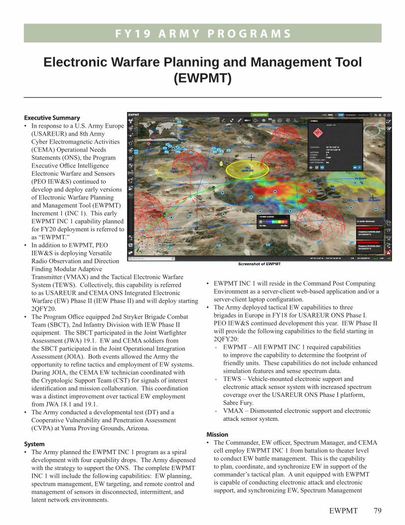
F Y 1 9 A R M Y P R O G R A M S
EWPMT 79
• EWPMT INC 1 will reside in the Command Post Computing Environment as a server-client web-based application and/or a server-client laptop configuration.
• The Army deployed tactical EW capabilities to three brigades in Europe in FY18 for USAREUR ONS Phase I. PEO IEW&S continued development this year. IEW Phase II will provide the following capabilities to the field starting in 2QFY20: - EWPMT – All EWPMT INC 1 required capabilities
to improve the capability to determine the footprint of friendly units. These capabilities do not include enhanced simulation features and sense spectrum data.
- TEWS – Vehicle-mounted electronic support and electronic attack sensor system with increased spectrum coverage over the USAREUR ONS Phase I platform, Sabre Fury.
- VMAX – Dismounted electronic support and electronic attack sensor system.
Mission• The Commander, EW officer, Spectrum Manager, and CEMA
cell employ EWPMT INC 1 from battalion to theater level to conduct EW battle management. This is the capability to plan, coordinate, and synchronize EW in support of the commander’s tactical plan. A unit equipped with EWPMT is capable of conducting electronic attack and electronic support, and synchronizing EW, Spectrum Management
Executive Summary• In response to a U.S. Army Europe
(USAREUR) and 8th Army Cyber Electromagnetic Activities (CEMA) Operational Needs Statements (ONS), the Program Executive Office Intelligence Electronic Warfare and Sensors (PEO IEW&S) continued to develop and deploy early versions of Electronic Warfare Planning and Management Tool (EWPMT) Increment 1 (INC 1). This early EWPMT INC 1 capability planned for FY20 deployment is referred to as “EWPMT.”
• In addition to EWPMT, PEO IEW&S is deploying Versatile Radio Observation and Direction Finding Modular Adaptive Transmitter (VMAX) and the Tactical Electronic Warfare System (TEWS). Collectively, this capability is referred to as USAREUR and CEMA ONS Integrated Electronic Warfare (EW) Phase II (IEW Phase II) and will deploy starting 2QFY20.
• The Program Office equipped 2nd Stryker Brigade Combat Team (SBCT), 2nd Infantry Division with IEW Phase II equipment. The SBCT participated in the Joint Warfighter Assessment (JWA) 19.1. EW and CEMA soldiers from the SBCT participated in the Joint Operational Integration Assessment (JOIA). Both events allowed the Army the opportunity to refine tactics and employment of EW systems. During JOIA, the CEMA EW technician coordinated with the Cryptologic Support Team (CST) for signals of interest identification and mission collaboration. This coordination was a distinct improvement over tactical EW employment from JWA 18.1 and 19.1.
• The Army conducted a developmental test (DT) and a Cooperative Vulnerability and Penetration Assessment (CVPA) at Yuma Proving Grounds, Arizona.
System• The Army planned the EWPMT INC 1 program as a spiral
development with four capability drops. The Army dispensed with the strategy to support the ONS. The complete EWPMT INC 1 will include the following capabilities: EW planning, spectrum management, EW targeting, and remote control and management of sensors in disconnected, intermittent, and latent network environments.
Electronic Warfare Planning and Management Tool (EWPMT)

F Y 1 9 A R M Y P R O G R A M S
80 EWPMT
Major Contractor Raytheon Space and Airborne Systems – Fort Wayne, Indiana
Operations, and CEMA across intelligence, maneuver, and communications functions.
• The Army intends a brigade equipped with IEW Phase II systems to be capable of conducting spectrum situational awareness, EW planning, dismounted and vehicle based direction finding, and electronic attack.
Activity • The SBCT employed IEW Phase II systems and Raven
Claw (an earlier version of the EWPMT software) during the JWA 19.1 in April 2019 at Yakima Training Center, Washington. - The 2-2 SBCT EW operators deployed in
TEWS-configured Stryker Double-V Hull (DVH) vehicles in support of the Cavalry squadron during JWA 19.1. Stryker DVH vehicles have an internal 570-amp alternator for power generation.
- JWA 19.1 was a coalition-level force-on-force training exercise. JWA 19.1 provided an opportunity to observe the operational employment and collect operator feedback of the IEW Phase II systems.
- Since JWA 19.1 was a training exercise, the Army did not develop an operational test plan for DOT&E approval.
• CEMA and EW soldiers from SBCT, Marine Corps Electromagnetic Spectrum Operations Cell personnel, and associated systems participated in JOIA. Marine Corps and Army Training and Doctrine Command conducted JOIA from June 4 – 13, 2019, at Camp Lejeune, North Carolina. The objective of the JOIA was to assess and experiment with inter-Service EW capabilities and inform the signals intelligence, EW and cyber operations concept, and capability development.
• The Army conducted a DT and CVPA to assess EWPMT interoperability at the Yuma Proving Grounds, Arizona, in July and August 2019. DOT&E approved the CVPA plan and observed both the DT and CVPA activities.
• The Army employed Raven Claw in the TEWS vehicle during JWA and JOIA. The EWPMT software will be in the IEW Phase II systems for integration of sensors.
• The Army is developing a Simplified Acquisition Management Plan (SAMP) for EWPMT INC 1. The SAMP defines the acquisition and test program and will be submitted to DOT&E for approval. The Army will use the SAMP in lieu of a Test and Evaluation Master Plan.
• The Army plans to conduct a DT with soldiers in October 2020. IOT&E is scheduled for April 2021.
Assessment • The Army is rebuilding EW capabilities lost after the end of
the Cold War. The Army continues to refine its doctrine to support the employment of tactical EW. The Army revised the Electronic Warfare Techniques publication in July 2019.
• Stryker vehicle batteries are not sufficient to support TEWS and VMAX equipment. Increased fuel consumption and aural signature limited employment of the TEWS. The TEWS-configured Stryker could operate on battery power for 20 minutes before requiring the engine to run to recharge the vehicle batteries.
• The Blue Force Tracker (BFT) network is the only method of digital communication from TEWS to brigade. During JWA, the BFT network was not reliable and often failed, with no alternate communication pathway. The volume of data processed and transmitted by EWPMT presents a challenge to the BFT network capacity. Should the network load from EWPMT exceed BFT capacity, data will be lost. As JWA did not include instrumented data collection, it is not possible to determine the extent of the loss.
• During JOIA, SBCT employed the EWPMT, TEWS, and VMAX sensor systems. The CEMA EW Technician coordinated with the CST for signals of interest identification and mission collaboration, received EW sensor information, and provided battle damage assessment and EW effect to the EW teams. This collaboration and coordination represents a distinct improvement over tactical EW employment from JWA 18.1 and 19.1.
• During the DT of EWPMT systems at Yuma Proving Ground, the Army demonstrated spectrum management, spectrum lines of bearing collection, geolocation creation, and target intelligence data nomination to the Advanced Field Artillery Tactical Data System. In line with the agile software development strategy, the Army demonstrated fixes and enhancements made in response to identified system deficiencies and soldier comments.
• The CVPA conducted during the DT identified cyber vulnerabilities. The Army intends to fix vulnerabilities identified and conduct a CVPA every 6 months to continue improving the security posture, with the next event tentatively scheduled for February 2020.
RecommendationsThe Army should:
1. Continue to refine doctrine to support tactical EW employment. As the Army refines doctrine, it should continue to improve coordination between EW and intelligence to provide EW crews with the essential

F Y 1 9 A R M Y P R O G R A M S
EWPMT 81
information required to discern between friendly and enemy target signals of interest.
2. In conjunction with the Network Cross-Functional Team and Integrated Tactical Network Program Office, identify a primary, alternate, contingency, and emergency communication plan for TEWS.
3. Conduct future developmental test events with operationally realistic threats, scenarios, sensors, and networks. Include appropriate instrumentation.
4. Continue efforts to increase vehicle operating time when main power is off.

82
F Y 1 9 A R M Y P R O G R A M S

F Y 1 9 A R M Y P R O G R A M S
IPPS-A 83
Electronic Transactions. Release 2 also provides soldiers with a new self-service capability to view their pay and personnel records and submit change requests.
Mission• Commanders will employ IPPS-A as a comprehensive
system for personnel accountability and strength information to support command decisions regardless of component or geographic location.
• Army components will use IPPS-A to manage their members across the full operational spectrum during peacetime and war, through mobilization and demobilization, capturing timely and accurate data throughout. Soldiers will use IPPS-A as a single, integrated personnel and pay system that will provide robust self-service capabilities, reducing the need for face-to-face interaction with their HR Professional for many transactions.
Major ContractorCACI – Arlington, Virginia
Executive Summary• Integrated Personnel
and Pay System – Army (IPPS-A) is a two increment program that streamlines Army Human Resources (HR) processes and enhances the efficiency and accuracy of Army personnel and pay procedures to support soldiers and their families.
• The Army Test and Evaluation Command (ATEC) conducted a Limited User Test (LUT) OT&E of IPPS-A Increment 2, Release 2 (Release 2) from January through February 2019 at the Pennsylvania Army National Guard (ARNG).
• Release 2 is effective and suitable to support the HR mission for the ARNG. Release 2 is survivable against a limited outsider cyber threat and is more secure than IPPS-A Increment I, Release 1 (Release 1). The capabilities available in this release are limited to personnel information for the ARNG; the IPPS-A Program Management Office (PMO) should continue to develop IPPS-A in order to deliver the full set of necessary capabilities to support the total Army Force.
System• IPPS-A streamlines Army HR processes and enhances the
efficiency and accuracy of Army personnel and pay procedures to support soldiers and their families. IPPS-A becomes the authoritative data source as the necessary functionality of the legacy systems is subsumed.
• IPPS-A is a web-based tool, available 24 hours a day, accessible to soldiers, HR Professionals, Combatant Commanders, personnel and pay managers, and other authorized users throughout the Army. The Army intends to use IPPS-A to improve the delivery of military personnel and pay services, and provide internal controls and audit procedures to prevent erroneous payments and loss of funds.
• Release 2 incorporates a subset of the total IPPS-A capability and will deploy only to the ARNG to replace the Standard Installation/Division Personnel System (SIDPERS) and
Integrated Personnel and Pay System – Army (IPPS-A) Increment II, Release 2
F Y 1 9 A R M Y P R O G R A M S
84 IPPS-A
• During operational testing, soldiers used Release 2 to view authoritative personnel information, make or request updates to their HR information, and completed all business processes with a success rate of greater than 90 percent. Prior to Release 2, soldiers had to visit an HR Professional to make or request updates to their HR records. Release 2 self-service capabilities improves the individual soldier’s ability to identify and correct erroneous information, and enables IPPS-A to drive the continuing Army data correctness campaign. During the LUT, Release 2 system logs recorded 1,359 self-service users and 154 self-service submissions including users self-updating their addresses, phone numbers, and personal email addresses. While self-service cannot fix all data errors in soldier records, self-service allows HR Professionals to focus on the areas beyond the scope of self-service.
• Release 2 provides an embedded help desk to resolve problems rapidly and with minimum disruption. Prior to Release 2, help desk support for SIDPERS was not available. In Release 2, automated workflows allow users to track the status of approvals. SIDPERS required workflows to complete outside of the system using email or paper that were difficult to track and required additional time and effort of the HR Professionals.
• HR Professionals received several capabilities to improve efficiency but the pre-defined queries do not fully support ARNG operations, such as readiness processing and readiness tracking. SIDPERS provides a single-page query while Release 2 users need to navigate through several screens to provide the same information. Development of a single-page query will improve the reports and analytics capability of Release 2.
• Users thought the Army would benefit from further deployment of IPPS-A and stated IPPS-A would improve the operational capability of their units.
• The observed best practices during the Release 2 LUT led to the success of the operational test.
Recommendation1. All Program Offices should adopt the best practices that led
to the success of the Release 2 LUT.
Activity• ATEC conducted a LUT at the Pennsylvania ARNG from
January 2019 through February 2019 in accordance with a DOT&E-approved test plan. ATEC also conducted a Cooperative Vulnerability and Penetration Assessment cyber test in August 2018 and an Adversarial Assessment cyber test during the LUT.
• In May 2019, ATEC observed the Release 2 deployment to the state of Virginia.
• In August 2019, ATEC observed the Release 2 deployment to the state of Maryland and Washington, D.C.
• As of September 30, 2019, IPPS-A has been fielded to the following states and territories: Pennsylvania, Virginia, Maryland, D.C., Connecticut, Maine, New Jersey, Delaware, and Massachusetts.
• During the Release 2 LUT, DOT&E observed and evaluated the following best practices:1. Test early with actual users on a production-representative
system. The IPPS-A PMO employed User Juries of actual users prior to operational testing to solicit usability feedback and identify problems with the system.
2. Test with a representative user base. The Release 2 LUT included users with different levels of responsibilities and different authorities, allowing for a holistic evaluation of the system.
3. Test when ready. When system problems and user feedback demonstrated that Release 2 was not ready for operational testing, the IPPS-A PMO extended the system acceptance testing by 3 months in order to address the problems.
4. Allow system changes during testing. The test-fix-test paradigm allowed the IPPS-A PMO to continue making changes to the software baseline after the start of the test. Continual communication between the test community, IPPS-A PMO, and System Integrator facilitated resolution of defects identified and enhanced understanding of actions taken for the resolution.
Assessment • Release 2 is operationally effective and suitable to support
the HR mission for the ARNG. Release 2 is survivable against a limited outsider cyber threat and is more secure than Release 1.

F Y 1 9 A R M Y P R O G R A M S
IVAS 85
The Army expects to receive delivery of 1,600 systems in September 2020.
Mission• Commanders of Army and Marine Corps close combat
formations and Special Operations Forces units will employ IVAS to achieve overmatch against near-peer threats identified in the National Defense Strategy. The Army intends to evolve the concept of operations in coordination with the joint force through experimentation as the system capabilities mature.
• Squads will train with IVAS in the Synthetic Training Environment in a high fidelity, live and mixed reality, immersive environment enabling rapid conduct and repetition of training scenarios.
Major ContractorMicrosoft – software developed in Redmond, Washington, and hardware developed in Mountain View, California
Executive Summary• On September 25, 2018, the Army Acquisition Executive
approved the Integrated Visual Augmentation System (IVAS) to proceed as a middle tier of acquisition rapid prototyping effort. The Army intends to deliver 2,550 IVAS prototype systems using an iterative approach of four capability sets.
• In March 2019, the Army executed Soldier Touch Point (STP) 1 to assess Capability Set 1 prototype capabilities in an operational environment. - Soldiers and marines equipped with IVAS Capability Set 1
navigated and maneuvered with the Heads-Up Display (HUD) and observed targets in low-light conditions. Warfighters trained in the Synthetic Training Environment, entering and clearing six rooms in a real-world building against virtual targets.
- Overall, warfighters responded favorably to surveys on the usability and perceived usefulness of IVAS.
• DOT&E observed STP 1 and submitted an evaluation to Congress as requested by the Chairman, Senate Armed Services Committee.
System• The IVAS is a HUD, body-worn computer, and networked
radio. • The Army intends IVAS to use a variety of imaging sensors,
artificial intelligence, and machine learning to provide a fully integrated day/night combat capability at the forward edge of the battlefield.
• The Army has structured IVAS as a middle tier of acquisition, 2-year prototyping period with four capability sets with software sprints and hardware builds. The Army and Microsoft will define each capability set in a design review based on the results from the previous capability set and overarching program goals. - The IVAS Capability Set 1 is Microsoft’s commercial
HoloLens 2 with an integrated commercial, thermal sensor, and Tactical Assault Kit software and maps. These prototypes operate on an internal battery and require a Wi-Fi network. The Army received delivery of 50 systems in March 2019.
- The IVAS Capability Set 2 will be a modified commercial prototype with integrated tactical radios and GPS capability. The Army expects to receive delivery of 300 systems in October 2019.
- The IVAS Capability Sets 3 will be the ruggedized military form factor with integrated low light and thermal sensors. The Army expects to receive delivery of 600 systems in June 2020.
- The IVAS Capability Set 4 will be the production-ready end-user device to provide enhanced squad lethality.
Integrated Visual Augmentation System (IVAS)

F Y 1 9 A R M Y P R O G R A M S
86 IVAS
Activity• On September 25, 2018, the Army Acquisition Executive
approved IVAS to proceed as a middle tier of acquisition rapid prototyping effort. In November 2018, the Army awarded an Other Transaction Agreement to Microsoft to develop IVAS.
• In March 2019, the Army executed STP 1 at Fort Pickett, Virginia, to assess Capability Set 1 prototype capabilities to determine if the HoloLens commercial technology could be adapted for military combat and training use.
• DOT&E observed STP 1 and submitted an evaluation to Congress as requested by the Chairman, Senate Armed Services Committee in July 2019. Since STP 1 was an experiment, the Army did not develop an operational test plan for DOT&E approval. - The test design include both demonstration activities
(performed once) and investigation activities (repeated with increasing complexity over time). STP 1 data collection consisted of recording whether warfighters successfully completed specified tasks, focus groups, and surveys aimed at gaining increased understanding of user acceptance.
- Soldiers and marines, organized into fire team units, conducted land navigation, trained in the Synthetic Training Environment, fired virtual M4 airsoft rifles with rapid target acquisition technology, and observed targets under low light conditions. IVAS operated on a Microsoft-provided network.
• The Army intends to execute STP 2 to assess Capability Set 2 in October and November 2019 at Fort Pickett, Virginia. Building on information learned from STP 1, the Army will conduct STP 2 with squad and platoon-sized units. DOT&E will observe STP 2.
Assessment• During STP 1, warfighters equipped with IVAS Capability
Set 1 demonstrated the following:- Navigation and maneuver indoors and outdoors using
Tactical Assault Kit software and maps integrated into the HUD
- Enter and clear six rooms as a team in a real-world building with virtual Synthetic Training Environment targets and content using synthetic M4 airsoft rifles and trackers. Following each experiment run through, warfighters received feedback about their performance including shots taken, kills, and shots received. Warfighters could replay their actions as avatars in a virtual after-action review.
- Shooting with rapid target acquisition-like technology against virtual targets. Upon completion, the HUD provided the shooter’s score.
- Observation of hidden and moving human targets during low-light conditions indoors, in a darkened room, and outdoors at day and night with an integrated thermal sensor.
- Live-fire shooting while wearing IVAS hardware.• The goal of STP 1 was to measure user acceptance and
military feasibility of IVAS. Overall, warfighters responded favorably to surveys on the usability, perceived usefulness, and acceptability of IVAS.
• The Army has not developed an experimentation and evaluation strategy, to include cybersecurity testing and integration in the tactical network, to guide the rapid prototyping efforts. An experimentation and evaluation strategy will help define scope and resources required for subsequent STPs.- A comparative evaluation between Army and marine
platoons equipped with IVAS and a baseline platoon against a robust opposing force would allow the Army to measure the stated program goal of increased lethality.
- The Army will need instrumentation for IVAS for future STPs and operational tests. The Army could find efficiencies by leveraging the embedded tools developed by Microsoft.
• The Program Office and Soldier Lethality Cross-Functional Team have maintained an environment of inclusiveness with DOT&E. DOT&E will remain engaged and report on subsequent Capability Sets and STPs.
RecommendationsThe Army should:
1. Develop an experimentation and evaluation strategy to guide rapid prototyping efforts.
2. Conduct a comparative evaluation between Army and Marine platoons equipped with IVAS and a baseline platoon against a robust opposing force.
3. Conduct STP 3 or 4 in conjunction with the Integrated Tactical Network to prove the brigade network is capable of supporting the increased bandwidth requirements and to gain understanding on limitations. IVAS should be assessed in each expected mode of operation (fight, rehearse, and train) and the corresponding communications conditions (jammed, contested, and permissive).
4. Work with Microsoft to determine how embedded IVAS instrumentation can be used to support both test and evaluation and training after action reviews.
5. Conduct a cyber-tabletop exercise.

F Y 1 9 A R M Y P R O G R A M S
JAGM 87
Activity• The Army conducted all operational and live fire testing in
accordance with the DOT&E-approved Test and Evaluation Master Plan and test plans. JAGM has not been tested in an active electronic warfare environment or against threats equipped with Active Protection Systems.
• The JAGM Program Office is continuing to test models utilizing a high-fidelity, all-digital simulation model to complement the test program and estimate hit performance throughout the engagement envelope. The Integrated Flight
Simulation (IFS) testing device used for developmental model testing includes: a six degree-of-freedom missile model, tactical flight software, scene generation models for laser and MMW scenes, target models, clutter models, aircraft models, atmospheric models, and countermeasure models.
• The Army conducted cybersecurity testing of JAGM at Redstone Arsenal, Alabama, in conjunction with the Adversarial Assessment of the Version 6 AH-64E in 3QFY19. The Threat Systems Management Office conducted the
- Avoiding alerting enemy vehicles of imminent attack and unwanted collateral damage
- Engaging multiple targets quickly• The HELLFIRE Romeo warhead Integrated Blast and
Fragmentation Sleeve (IBFS) detonates with a programmable delay fuse and a Height-of-Burst (HOB) feature. This updated warhead blast provides a capability to engage armored vehicles, while the IBFS and HOB feature is designed to engage personnel in the open. The programmable delay allows time for the warhead to penetrate deep into a building, bunker, or lightly armored vehicle before detonating to incapacitate the personnel and destroy the equipment inside.
MissionArmy and Marine Corps commanders employ JAGM from rotary-wing and unmanned aircraft to engage enemy combatants in stationary and moving armored and unarmored vehicles, within complex building and bunker structures, in small boats, and in the open.
Major ContractorLockheed Martin Corporation, Missiles and Fire Control Division – Grand Prairie, Texas
Executive Summary• The Army conducted a Joint Air-to-Ground Missile (JAGM)
IOT&E in conjunction with the Version 6 AH-64E Apache Attack helicopter FOT&E II in 3QFY19. The Marine Corps will conduct an additional IOT&E in 2QFY20 to assess performance with Marine Corps attack helicopters.
• JAGM meets the Key Performance Parameter for probability of hit and meets the inflight reliability requirement when launched from the AH-64E.
• AH-64E aircrews demonstrated effective employment of JAGM in force-on-force missions against realistic targets in the IOT&E. The AH-64E pilot vehicle interface enables efficient employment of all JAGM modes, giving aircrews increased effectiveness in degraded visibility, against threat countermeasures, against multiple targets, and against targets in realistic operational terrain.
• JAGM maintains the lethality of the legacy HELLFIRE Romeo against target-representative light and heavy-armored ground combat vehicles, trucks, and boats; personnel in the open; and behind brick over block and adobe walls while adding a fire and forget capability.
System• JAGM is an air-to-ground, precision-guided missile with two
new seekers that replicate and combine capabilities of the existing laser-guided HELLFIRE Romeo and radar-guided Longbow HELLFIRE missiles.
• The JAGM design combines two sensor technologies – semi-active laser and millimeter wave (MMW) radar – into a single seeker and guidance system and mated it to the HELLFIRE Romeo warhead, motor, and flight control systems. The dual-seeker engagement modes optimize missile performance while minimizing aircraft exposure to enemy observation and fire by:- Destroying targets obscured by countermeasures or
obscurants- Providing target location updates to an inflight missile
Joint Air-to-Ground Missile (JAGM)
F Y 1 9 A R M Y P R O G R A M S
88 JAGM
assessment in an aircraft hangar with a JAGM and missile launcher attached to an AH-64E.
• The JAGM Program Office has completed integrated developmental/operational test shots of 70 missiles as of September 2019. The missile shots spanned the engagement envelope for target type, speed, range, and obscuration. Targets were located in realistic battlefield terrain and aircrews employed tactical maneuvers and procedures.
• The Army Test and Evaluation Command conducted an IOT&E in April through May 2019 at Fort Hood, Texas, and Eglin AFB, Florida. During the IOT&E, operational pilots fired six missiles in all JAGM engagement modes against stationary and moving, maritime and land targets in daytime conditions. During IOT&E, two maritime JAGM shots using a new maritime trajectory hit their targets, but did not produce the desired lethal effects. The program manager has suspended further maritime testing to analyze those results and refine missile software for maritime engagements.
• During all phases of the live missile testing, 13 of the armored targets were obscured or covered by threat countermeasures (smoke, dust, radar reflectors, and/or camouflage netting). Missile testing in FY19 featured shots against targets in realistic operational terrain and against multiple simultaneous moving targets.
• Live fire testing in FY19 included shots against an up-armored T-72, a BMP infantry fighting vehicle, personnel in the open, and behind brick over block and adobe walls.
Assessment• In preliminary testing to date, JAGM met hit performance
and reliability requirements when launched by Version 4.5 and Version 6 AH-64E software. JAGM demonstrated performance requirements for probability of hit, even though many of the targets were obscured by countermeasures or dust. The IFS provided valid hit-point estimates for 49 pre-Milestone C shots. The validated IFS model confirms that JAGM maintains lethality of the HELLFIRE Romeo missile. JAGM demonstrated its inflight and overall reliability requirements with the live missile shots.
• JAGM has been fired in all dual-seeker modes during early Army testing. JAGM destroyed targets aircrews would frequently bypass when armed with HELLFIRE due to tactical considerations. The fire-and-forget capability of the dual-seeking JAGM allowed aircrews the flexibility to engage
air defense systems with minimal aircraft exposure. Battlefield obscurants did not reduce observed accuracy during JAGM engagements.
• FY19 JAGM testing has demonstrated lethality against the up-armored T-72 and improved lethality against light-armored vehicles compared to past JAGM and HELLFIRE Romeo live fire tests using a new delayed fusing capability to delay warhead detonation until after missile penetration. Testing demonstrated improved lethality against personnel behind brick over block and adobe walls versus tests performed in FY18 by optimizing fuse delay timing, equaling HELLFIRE Romeo performance against these targets. The presence of nearby vehicles can increase the expected height of burst when attacking personnel in the open, a consideration that will be addressed in future testing and operational planning.
• The workload and usability scores for the dual-seeker JAGM are similar to the legacy single-seeker HELLFIRE. JAGM met all mission requirements with minimal workload demands during engagements.
• JAGM will require the Army to develop new tactics, techniques, and procedures due to technical differences with the HELLFIRE. The Army must develop a JAGM training device to support differences in training.
• The Army discovered no critical cybersecurity vulnerabilities during the AH-64E JAGM Adversarial Assessment. The Marine Corps will conduct additional cybersecurity testing of JAGM and its shipping container in conjunction with the Marine Corps IOT&E in 2QFY20.
• JAGM has not been tested in an active electronic warfare environment or against threats equipped with Active Protection Systems. These emerging threat capabilities may limit JAGM performance and the Army intends to evaluate this in future testing.
RecommendationsThe Army should:
1. Develop, test, and field a JAGM training missile to train pilots on effective employment of JAGM.
2. Evaluate JAGM in an operational electronic warfare environment.
3. Plan and conduct appropriate test and evaluation of new JAGM capabilities as they are developed.
4. Plan and conduct testing of the effectiveness of JAGM against emerging threat armor Active Protection Systems.

F Y 1 9 A R M Y P R O G R A M S
JAB 89
Activity• All testing was conducted in accordance with the
DOT&E-approved Test and Evaluation Master Plan and test plans.
• The Army conducted the JAB IOT&E at Fort Bliss, Texas, April 2 – 29, 2019. The test unit consisted of Armored and Engineer elements from 2nd Brigade, 1st Armored Division. Test events included combined-arms and in-stride breaching operations. The Army conducted a cybersecurity Adversarial Assessment.
• The JAB LFT&E program completed in March 2018, and included Automatic Fire Extinguishing System tests, armor tests, controlled damage experiments, components/system-level and full-up system-level tests
against underbody blast mine threats and direct- and indirect-fire threats.
• In FY19, the Program Office developed several vehicle design changes to mitigate some of the vulnerabilities found during the LFT&E program. The Army is expected to complete the follow-on testing in 1QFY20 to determine the effect of these changes on vehicle survivability and force protection.
Assessment• Poor system reliability limited availability of JAB systems
during the IOT&E. The result was insufficient data for DOT&E to determine operational effectiveness.
supportability, and enabling use of common battlefield communication suites.
• The JAB is an Acquisition Category II program. The overall Acquisition Objective for JAB is 365 items. The Army will purchase 337 assets. The Marine Corps will purchase 28 assets.
MissionCommanders employ JAB to enable the ABCT and MAGTF to close with and destroy the enemy by maneuvering over natural and man-made obstacles that would otherwise prevent freedom of maneuver.
Major Contractor Leonardo DRS Technologies, Inc. – St. Louis, Missouri
Executive Summary• The Army conducted the Joint Assault Bridge (JAB) IOT&E
at Fort Bliss, Texas, April 2 – 29, 2019. Poor system reliability limited availability of JAB systems during the IOT&E. The result was insufficient data for DOT&E to determine operational effectiveness.
• The Army is developing a plan to correct deficiencies identified during and following the IOT&E. The Army has scheduled a second IOT&E in 3QFY20 at Fort Riley, Kansas.
• In FY19, the Program Office implemented several JAB design changes to mitigate some of the vulnerabilities identified during the JAB LFT&E in 2018. The Army is on schedule to start follow-on live fire testing in 1QFY20 to evaluate the effect of these changes on vehicle survivability.
System• The JAB replaces the Wolverine and M48/M60 chassis-based
Armored Vehicle Launched Bridge systems in the Armored Brigade Combat Team (ABCT) Brigade Engineer Battalions and in Mobility Augmentation Companies supporting ABCT operations.
• The JAB was designed to support M1 Abrams-equipped units in Marine Air Ground Task Forces (MAGTF). The Army assumed the lead for the JAB program in 2010 after the Marine Corps canceled the program due to cost and performance concerns. The Marine Corps remains involved and is seeking to procure 28 JAB systems in conjunction with the Army.
• The design concept includes an M1A1 Abrams chassis with M1A2 heavy suspension, and a contractor-designed, integrated hydraulic bridge launch mechanism for the Military Load Classification-95 Bridge.
• The Services intend JAB to improve survivability and provide improved mobility ensuring freedom of maneuver, improved
Joint Assault Bridge (JAB)

F Y 1 9 A R M Y P R O G R A M S
90 JAB
• The Army is developing a plan to correct deficiencies identified during and following the IOT&E. The Army has scheduled a second IOT&E in 3QFY20 at Fort Riley, Kansas. Preliminary JAB survivability analysis identified several vehicle design vulnerabilities that could adversely affect crew survivability and the ability of the unit equipped with JAB to continue to execute their mission. The Program Office is working with the vendor to develop and incorporate design changes intended to improve the JAB survivability in combat.
• A combined operational and live fire report is planned for 2QFY20. The details of the survivability and force protection
evaluation of the JAB will be available in the classified section of the report.
RecommendationsThe Army should:
1. Continue to correct vulnerabilities identified in live fire test to increase the ability of the unit equipped with JAB to continue to conduct its mission after a combat engagement.
2. Correct deficiencies identified during IOT&E and validate those fixes and mitigation techniques in test.

F Y 1 9 A R M Y P R O G R A M S
JLTV 91
• The program plans to procure approximately 49,099 vehicles for the Army, 15,390 vehicles for the Marines, and 180 vehicles for the Air Force.
Mission• Army and Marine Commanders employ units equipped with
JLTV as a tactical-wheeled vehicle to support all types of military operations. Airborne, air assault, amphibious, light, Stryker, and heavy forces use JLTVs as reconnaissance, maneuver, and maneuver sustainment platforms. Air Force units intend to employ JLTVs for security and special operations.
• Small ground combat units will employ JLTV in combat patrols, raids, long-range reconnaissance, and convoy escort.
Major ContractorOshkosh Corporation – Oshkosh, Wisconsin
Executive Summary• The Army Acquisition
Executive approved the Joint Light Tactical Vehicle (JLTV) program to enter Full-Rate Production in May 2019.
• OSD approved the JLTV Family of Vehicle (FoV) Test and Evaluation Master Plan (TEMP) update in May 2019 for the production and deployment phase of the program.
• The Marine Corps Operational Test and Evaluation Activity (MCOTEA) conducted the JLTV FOT&E in August 2019 at Camp Lejeune, North Carolina, in accordance with the DOT&E-approved Operational Test Plan.
System• The JLTV FoV is the partial replacement for the
High-Mobility Multipurpose Wheeled Vehicle (HMMWV) fleet for the Army, Marine Corps, and Air Force. The Services intend the JLTV to provide increased crew protection against IEDs and underbody attacks, improved mobility, and higher reliability than the HMMWV.
• The JLTV FoV consists of two mission categories: the JLTV Combat Tactical Vehicle, designed to seat four passengers, and the JLTV Combat Support Vehicle, designed to seat two passengers.
• The JLTV Combat Tactical Vehicle has a 3,500-pound payload and three mission package configurations: - General Purpose Variant- Heavy Guns Carrier Variant- Close Combat Weapon Carrier Variant
• The JLTV Combat Support Vehicle has a 5,100-pound payload and one mission package configuration:- Utility Prime Mover Variant that can accept a Troop Seat
Kit to carry up to eight soldiers or a cargo shelter
Joint Light Tactical Vehicle (JLTV)

F Y 1 9 A R M Y P R O G R A M S
92 JLTV
Activity• The program developed upgrades to address some of the
operational deficiencies identified in the 2018 Multi-Service Operational Test and Evaluation.
• In April 2019, the Army Test and Evaluation Command conducted the JLTV Soldier Demonstration at Fort Stewart, Georgia, to collect soldier feedback on vehicle upgrades.
• The Army Acquisition Executive approved the JLTV program to enter full-rate production in May 2019.
• OSD approved the JLTV FoV TEMP update in May 2019 for the production and deployment phase of the program.
• MCOTEA conducted the JLTV FOT&E in August 2019 at Camp Lejeune, North Carolina, in accordance with the DOT&E-approved Operational Test Plan. The FOT&E provided data to assess a Marine Unit accomplishing missions employing the Marine Command, Control, and Communication equipment and JLTV Engineering Change Proposals (ECPs).- Mounted Family of Computer Systems (MFoCS)- Troop Seat Kit (TSK)- JLTV Trailer
Assessment• Based on early analysis of the FOT&E, a Marine Weapons
Company with the JLTV can conduct combat and mortar fire support missions. - The Mortar Section with the JLTV TSK accomplished
mortar fire missions similar to a Mortar Section with the HMMWV Troop Carrier. The JLTV mobility expanded the terrain available for the Mortar Section to set up and conceal their position.
- Several failures of the electronic weapons turret required manual operations affected timely fire engagements. The Marines need to ensure fielded weapon systems are restored to operational condition prior to integrating on the JLTV.
- The lack of a means to communicate between marines transported in the rear of the JLTV TSK, the driver, and commander in the cab is a safety deficiency particularly while the vehicle is moving over rough terrain.
- Voice and Digital communication from the vehicle was poor, delayed, and degraded mission accomplishment.
- Trained marines were successful at using the MFoCS with Joint Battle Command – Platform (JBC-P) for planning and administrative reporting.
- Marines experienced degraded position location information during some missions. Marines lost confidence in displayed information for use in decision-making and situational awareness.
• The Soldier Demonstration provided the program with early user feedback to the planned upgrades to the JLTV prior to production planned for December 2019. The program is incorporating user feedback into vehicle modification decisions.- Soldier feedback was positive on the larger rear door
windows to increase visibility close in and around the vehicle.
- The forward facing camera provided additional awareness of conditions in front of vehicle to enable the driver to effectively maneuver across terrain and avoid obstacles.
- The addition of the muffler lessened the external noise from the vehicle compared to the baseline JLTV.
- The noise abatement material added to JLTV did not reduce cab interior noise. The majority of soldiers assessed the intercom system as essential for communicating in the cab. Soldiers commented that the interior noise level seemed to increase at higher vehicle speeds.
- Soldiers assessed the height of the canopy cover of the TSK as too high for some tactical missions and susceptible to damage in a high foliage environment. The program is pursuing a reduced height canopy cover in addition to current configuration.
- The cargo troop strap and low tailgate across the rear of the TSK does not provide adequate protection to prevent soldiers or mission equipment from being ejected out of the cargo bed during movement. The program is investigating a design change to the rear strap to resolve this problem.
Recommendation1. The Marines should develop a plan to correct performance
deficiencies of the Marine command, control, and communication equipment integrated on the JLTV and other shortcomings discovered during the Marine JLTV FOT&E.

F Y 1 9 A R M Y P R O G R A M S
PIM 93
Activity• DOT&E submitted a report to Congress for the second IOT&E
in July 2018 and the LFT&E report in June 2018.• In FY19, the Army conducted developmental testing to
address fixes to breech reliability failures demonstrated during the first IOT&E in FY17 and the second IOT&E in FY18. The Army conducted three engineering tests to assess the
interim fixes for the breech. Following engineering test 3, the Army selected final configurations for updated breech parts. The final configuration, including modifications to the breech, include the firing mechanism, breech spring packs, cam and roller, and block stop and carrier plunger. These breech fixes
- The base T1 armor configuration is integral to the SPH and CAT. The Army intends the T2 configuration to meet protection requirements beyond the T1 requirement with add-on armor kits.
- The Army plans to employ PIM vehicles in the T1 configuration during normal operations and will equip the SPH and CAT with T2 add-on armor kits during combat operations.
• The Army intends to employ the M109 FoV as part of a Fires Battalion in the Armored Brigade Combat Team and Artillery Fires Brigades. The Army plans to field up to 689 sets of the M109 FoV with an FRP planned for FY20.
MissionCommanders employ field artillery units equipped with the M109 FoV to destroy, defeat, or disrupt the enemy by providing integrated, massed, and precision indirect fire effects in support of maneuver units conducting unified land operations.
Major Contractor BAE Systems – York, Pennsylvania
Executive Summary• In FY18, the Army conducted a second IOT&E on the
M109A7 Family of Vehicles (FoV) Paladin Integrated Management (PIM) program that confirmed the Self-Propelled Howitzer (SPH) remained not operationally suitable in environments that require the highest propelling charge, Modular Artillery Charge 5H.
• In FY19, the Army conducted developmental testing of the SPH to increase reliability and address improvements to the breech deficiencies the Army discovered in the FY18 IOT&E.
• The Army delayed the Full-Rate Production (FRP) decision to FY20 due to BAE-York Systems production line quality and capacity challenges.
• The Army recalled 68 PIM low-rate initial production (LRIP) vehicles for complete teardown, inspection, repair, and retesting due to weld deficiencies identified in the BAE production process at York, Pennsylvania.
• The Army plans to conduct missions with soldier crews in February 2020, as part of the phase two breech reliability testing, and to fire high-angle missions not completed during the second IOT&E.
System• The M109 FoV PIM program consists of two vehicles:
the SPH and Carrier Ammunition Tracked (CAT) resupply vehicle.- The M109A7 SPH is a tracked, self-propelled 155-mm
howitzer designed to improve sustainability over the legacy M109A6 SPH.
- The M992A3 CAT supplies the SPH with ammunition. The ammunition carriers have a chassis similar to the SPH. The ammunition carriers are designed to carry 12,000 pounds or 98 rounds of ammunition in various configurations. A crew of four soldiers operates the CAT.
- The Army will equip the SPH and CAT with two armor configurations to meet two threshold requirements for force protection and survivability – Threshold 1 (T1) and Threshold 2 (T2).
M109A7 Family of Vehicles (FoV) Paladin Integrated Management (PIM)

F Y 1 9 A R M Y P R O G R A M S
94 PIM
will undergo durability testing at Yuma Proving Ground, Arizona, in October through December 2019.
• The Army will continue to conduct developmental testing to address breech reliability fixes and will address missions not fired during the IOT&E. These include firing the Modular Artillery Charge System 5H at high quadrant elevation, in an excursion event with soldier crews as part of the breech reliability testing during follow-on testing in February 2020.
• The Army has recalled 68 PIM LRIP vehicles for complete teardown, inspection, repair, and retesting due to weld deficiencies in the BAE production process at York, Pennsylvania.
• PEO Ground Combat Systems (GCS), Defense Contracting Management Agency, and the contractor have addressed welding specifications with the goal of improving quality.
• Contractor production has been behind schedule due to production line quality deficiencies and production capacity; however, it has demonstrated reaching production capacity the past couple of months.
• PEO GCS has been actively engaged in continuing assessments of the contractors’ efforts at York, Pennsylvania, facilities.
• The Army delayed the FRP decision due to production quality and capacity challenges in the York, Pennsylvania, production facility. The contractor has generated a corrective action plan addressing noncompliance of production quality and production capacity.
• The Army designed an underbody kit to provide protection for SPH and CAT against IEDs similar to those encountered in Iraq and Afghanistan. The Army purchased five underbody kits for test purposes. The Army intends to purchase 540 underbody kits as Theater Provided Equipment to equip the SPH or CAT.
• The Army is finalizing concepts for design and production of an extended-range cannon artillery system and breech assembly. The Army intends to use the PIM chasis, engine, transmission, and turret for this extended-range cannon.
Assessment• Analysis is ongoing regarding improved breech reliability
testing. DOT&E will provide an operational assessment in May 2020, regarding the results of phase two breech reliability testing.
• The contractor faces significant capacity challenges in the near future with the production of multiple Army and Marine Corps armored combat vehicle programs.
• The Program Office has taken action to correct deficiencies identified in early testing and to validate associated fixes using Developmental Performance, Automotive, and LFT&E programs.- Corrective action initiatives include developmental testing
of breech component improvements in a three-phased strategy consisting of a series of engineering tests, a 1,000 round durability test, and a developmental/operational follow-on test to assess breech reliability improvements.
- Additional improvement initiatives include a series of software updates and hardware redesigns to address reliability failures revealed during operational testing. Software upgrades address weapon system performance and maintenance fault generation anomalies. Hardware efforts include development of a Hatch Centric Weapons Station to replace the Crew Remotely Operated Weapon Station.
- During armor exploitation testing, most of the modified armored areas demonstrated that they provide protection against Key Performance Parameter threats.
- Changes to the CAT crew compartment Automatic Fire Extinguisher System (AFES) mitigate the deficiency identified in early testing and reduce its vulnerability to fires.
• The crew compartment AFES in the SPH was designed to protect a small, localized area and is deficient in providing adequate fire survivability. The Program Office is modifying the crew compartment AFES to improve SPH crew survivability to fires.
RecommendationsThe Army should:
1. Continue to pursue the final design, development, and integrated testing of a new cannon and breech assembly to address legacy breech and cannon reliability to mitigate range and rate of fire shortcomings in the M109A7 SPH.
2. Consider stockpiling breech parts with deployed artillery units or prepositioned fleets to support legacy M109A6 SPH and M109A7 SPH.
3. Correct the deficiencies in the SPH’s crew compartment AFES and validate those fixes in test.

F Y 1 9 A R M Y P R O G R A M S
MCE 95
Activity• The Army began this program in FY16, and DOT&E put it on
oversight in FY17. This is the first time DOT&E has included this program in its annual report.
• In November 2018, the Army conducted an MCE CT as part of the Network Integration Evaluation (NIE) 18.2. The operational test consisted of three armored cavalry troops
of the 5th Squadron, 73rd Cavalry Regiment conducting operationally realistic missions at Fort Bliss, Texas, and White Sands Missile Range, New Mexico. The 1st Battalion, 508th Infantry Regiment augmented with electronic warfare and cyber capabilities served as a realistic opposing force.
Environment, and interoperate with joint, allied, and coalition forces.
• The Army intends for MCE to replace the following fielded capabilities:- JBC-P- Force XXI Battle Command Brigade and Below family of
systems • The Blue Force Tracker 2 (BFT2) satellite network supports
the MCE for mobile operations. MissionArmy tactical commanders will use MCE to provide integrated, on-the-move, mission command information and situational awareness to maneuver platforms throughout the unit’s area of operations. Brigade and battalion-level units will employ MCE to gain near real-time situational awareness and mission command capability to assist in the accomplishment of their combat missions.
Major ContractorCombat Capabilities Development Command, System Simulation, Software and Integration – Huntsville, Alabama
Executive Summary• In November 2018, the
Army conducted a Mounted Computing Environment (MCE) Customer Test (CT) to evaluate two candidate MCE software systems: Mounted Mission Command (MMC) and Mounted Android Tactical Assault Kit (MTAK). The MCE CT consisted of three armored cavalry troops conducting operationally realistic missions at Fort Bliss, Texas, and White Sands Missile Range, New Mexico.
• The MCE CT provided the following assessment of the candidate MCE software solutions:- Neither candidate system provided on-the-move mission
command support equivalent to the fielded Joint Battle Command – Platform (JBC-P).
- Both systems demonstrated the need for further development in the areas of performance, reliability, training, and cybersecurity.
• The Army is producing an MCE Test and Evaluation Master Plan (TEMP) to provide a test strategy that includes lab- and unit-based development, and an MCE IOT&E planned for FY22.
System• The Army designed the MCE as an on-the-move, networked
mission command information system that enables units to:- Share near real-time friendly and enemy situational
awareness information- Share common operational maps and graphics- Transmit and receive command and control messages- Conduct interactive communications via chat rooms
• MCE will interface and share data with other computing environments as part of the Army’s Common Operating Environment, such as the Command Post Computing
Mounted Computing Environment (MCE)

F Y 1 9 A R M Y P R O G R A M S
96 MCE
The Army conducted the MCE CT in accordance with a DOT&E-approved operational test plan.
• The Army conducted the MCE CT to evaluate two candidate MCE mission command software systems:- MMC, similar to the Mission Command Information
System employed in the Command Post Computing Environment
- MTAK, similar to the Android Tactical Assault Kit (ATAK) employed in the Nett Warrior program
• During FY19, the Army conducted laboratory-based integration testing of MCE solutions, and intends to publish the results in 2020.
• The Army is producing an MCE TEMP to provide a test strategy that includes lab- and unit-based development, and an MCE IOT&E planned for FY22.
Assessment• During NIE 18.2, neither MMC nor MTAK provided
on-the-move mission command support equivalent to the fielded JBC-P. Unlike JBC-P, both candidate MCE systems displayed stale Common Operational Picture information without indication of data currency, did not support the creation and transmission of field order messages, and produced excessive bandwidth demands upon the low-bandwidth BFT2 satellite network. The Army did not assess
satellite bandwidth usage for either variant of MCE employed during test.
• MTAK was more reliable, available, and maintainable than the MMC. MTAK met its maintainability requirement and was close to meeting its availability requirement, but did not meet its reliability requirement. The MMC did not meet its reliability, availability, and maintainability requirements.
• Soldiers used chat rooms as primary MCE communications, and experienced chat rooms that often froze and required the creation of new chat room sessions.
• Training afforded soldiers the knowledge to complete simple tasks, but did not support complex tasks or troubleshooting. Soldiers viewed MTAK as intuitive, and were able to improve their operation and troubleshooting skills as the test progressed.
• MCE demonstrated cybersecurity vulnerabilities that reduce mission success.
RecommendationsThe Army should:
1. Complete the MCE TEMP to support future integrated testing of MCE.
2. Continue the development of an MCE solution that addresses the deficiencies found during the MCE CT.
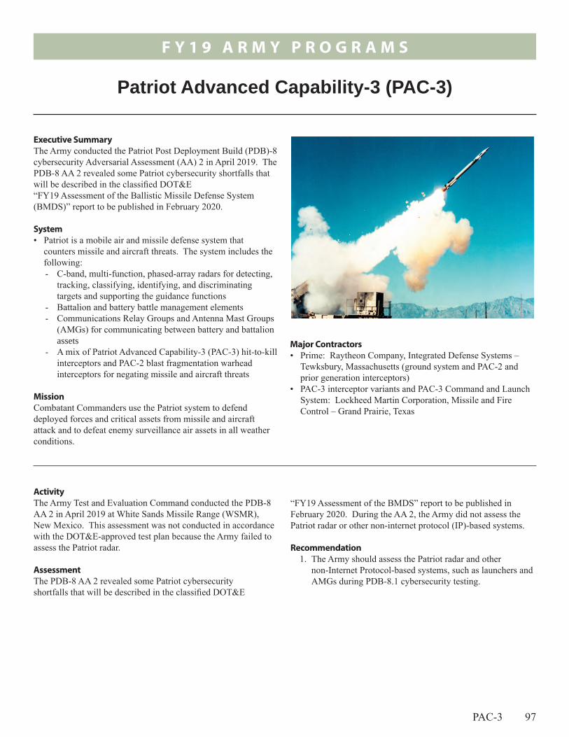
F Y 1 9 A R M Y P R O G R A M S
PAC-3 97
ActivityThe Army Test and Evaluation Command conducted the PDB-8 AA 2 in April 2019 at White Sands Missile Range (WSMR), New Mexico. This assessment was not conducted in accordance with the DOT&E-approved test plan because the Army failed to assess the Patriot radar.
Assessment The PDB-8 AA 2 revealed some Patriot cybersecurity shortfalls that will be described in the classified DOT&E
“FY19 Assessment of the BMDS” report to be published in February 2020. During the AA 2, the Army did not assess the Patriot radar or other non-internet protocol (IP)-based systems.
Recommendation1. The Army should assess the Patriot radar and other
non-Internet Protocol-based systems, such as launchers and AMGs during PDB-8.1 cybersecurity testing.
Major Contractors• Prime: Raytheon Company, Integrated Defense Systems –
Tewksbury, Massachusetts (ground system and PAC-2 and prior generation interceptors)
• PAC-3 interceptor variants and PAC-3 Command and Launch System: Lockheed Martin Corporation, Missile and Fire Control – Grand Prairie, Texas
Executive SummaryThe Army conducted the Patriot Post Deployment Build (PDB)-8 cybersecurity Adversarial Assessment (AA) 2 in April 2019. The PDB-8 AA 2 revealed some Patriot cybersecurity shortfalls that will be described in the classified DOT&E “FY19 Assessment of the Ballistic Missile Defense System (BMDS)” report to be published in February 2020.
System• Patriot is a mobile air and missile defense system that
counters missile and aircraft threats. The system includes the following: - C-band, multi-function, phased-array radars for detecting,
tracking, classifying, identifying, and discriminating targets and supporting the guidance functions
- Battalion and battery battle management elements- Communications Relay Groups and Antenna Mast Groups
(AMGs) for communicating between battery and battalion assets
- A mix of Patriot Advanced Capability-3 (PAC-3) hit-to-kill interceptors and PAC-2 blast fragmentation warhead interceptors for negating missile and aircraft threats
MissionCombatant Commanders use the Patriot system to defend deployed forces and critical assets from missile and aircraft attack and to defeat enemy surveillance air assets in all weather conditions.
Patriot Advanced Capability-3 (PAC-3)

F Y 1 9 A R M Y P R O G R A M S
98

F Y 1 9 A R M Y P R O G R A M S
SPS 99
Major Contractors• VTP Low-Rate Initial Production Vendors:
- Engense Armor Systems – Camarillo, California (ESBI)- Florida Armor Group – Miami Lakes, Florida (ESBI)- Leading Technology Composites – Wichita, Kansas
(ESAPI, ESBI)- TenCate Armor – Hebron, Ohio (ESAPI) - 3M/Ceradyne – Costa Mesa, California (ESAPI, XSAPI)
• TEP Full-Rate Production Vendors/Designs (Multiple vendors to stimulate competition and achieve best price through Fair Opportunity awards):- KDH Defense Systems Inc. – Eden, North Carolina
(MSV, BPP) - Bethel Industries Inc. – Jersey City, New Jersey
(MSV, BPP)- Point Blank (Protective Apparel & Uniform) – Pompano
Beach, Florida (BCS)- Carter Enterprises Industries Inc. – Brooklyn, New York
(BCS)- Eagle Industries Unlimited – Virginia Beach, Virginia
(BCS)• IHPS Vendor:
- 3M/Ceradyne – Costa Mesa, California
Executive Summary• The Soldier Protection System (SPS) consists of four
subsystems: Vital Torso Protection (VTP); Torso and Extremity Protection (TEP); Integrated Head Protection System (IHPS); and Military Combat Eye Protection (MCEP). Each subsystem has its own acquisition strategy.
• The SPS TEP, VTP, IHPS, and MCEP met ballistic requirements.
• The Army began testing new, lighter-weight VTP designs in 3QFY19.
System• The SPS is a suite of personal protection subsystems intended
to, at a reduced weight, provide equal or increased levels of protection against small-arms and fragmenting threats compared to existing personal protection equipment. The SPS subsystems are designed to protect a soldier’s head, eyes, and neck region; the vital torso and upper torso areas, as well as the extremities; and the pelvic region. Soldiers can configure the various components to provide different tiers of protection depending on the threat and the mission.
• The SPS consists of four subsystems:- VTP consists of front and rear hard armor torso plates
(either the Enhanced Small Arms Protective Insert (ESAPI) or the X Threat Small Arms Protective Insert (XSAPI)) and the corresponding hard armor side plates (either Enhanced Side Ballistic Insert (ESBI) or the X Threat Side Ballistic Insert (XSBI)).
- TEP consists of the soft armor Modular Scalable Vest (MSV) with provision for adding the Ballistic Combat Shirt (BCS) for extremity protection and the Blast Pelvic Protector (BPP) for pelvic and femoral artery protection.
- IHPS consists of a helmet, with provision for adding a mandible and/or visor for mounted use.
- MCEP is a selection of protective eyewear validated for use by Army personnel. The Army’s Authorized Protective Eyewear List (APEL) includes all authorized protective eyewear.
• Soldiers currently receive SPS components through the Army Rapid Fielding Initiative (RFI). The Army plans to field the complete SPS to the Close Combat Force, which includes Infantry, Engineers, and Scouts with habitual attachments (i.e. combat medics, forward observers). The Army plans to subsequently field SPS to the broader Army as quantities are available.
MissionUnits will accomplish assigned missions with soldiers wearing the SPS that provides protection against injury from a variety of ballistic (small-arms and fragmenting) threats.
Soldier Protection System (SPS)

F Y 1 9 A R M Y P R O G R A M S
100 SPS
Activity• The development, testing, and production/fielding of the
four SPS subsystems (TEP, VTP, IHPS, and MCEP) have been on different timelines. The Army made a Full-Rate Production decision for the TEP in September 2016 and the IHPS in October 2018. The Army completed VTP testing in February 2018. Each SPS subsystem is compatible with existing (legacy) personal protective equipment (for example, soldiers can use existing hard armor plates in the new MSV).
• The Army began testing new, lighter-weight VTP designs from multiple vendors in 3QFY19. Upon completion of testing, the Army intends to make a subsequent Full-Rate Production decision on these lighter-weight VTP designs.
• The Army is testing VTP ballistic performance in accordance with DOT&E-approved test plans.
• The Army plans to complete additional full-up system-level testing of the SPS (with all subsystems combined) against additional threats in 1QFY21.
AssessmentAs testing is ongoing, analysis is not complete. DOT&E will report on VTP and SPS ballistic performance upon the completion of testing in 1QFY21.
RecommendationsNone.

F Y 1 9 A R M Y P R O G R A M S
Spider 101
- A repeater or communications relay device for use in difficult terrain or at extended ranges.
• Spider incorporates self-destructing and self-deactivating technologies to reduce residual risks to non-combatants and has the capability to use non-lethal munitions, such as the Modular Crowd Control Munition that fires rubber sting balls.
• The Army fielded Spider Increment 1 systems in FY09 under an urgent materiel release. The system reached Initial Operational Capability in FY11 and obtained its full materiel release in FY13.
MissionBrigade Combat Team commanders employ engineer units equipped with Spider to provide force protection and counter mobility obstacles using lethal and non-lethal munitions. Spider functions either as a stand-alone system or in combination with other obstacles to accomplish the following:• Provide early warning• Protect the force• Delay and attrite enemy forces• Shape the battlefield
Major ContractorCommand and Control hardware and software: Northrop Grumman Information Systems Sector, Defense Systems Division – Redondo Beach, California
Executive Summary• The Army conducted the Spider Increment 1A (I1A) IOT&E
in October 2018, at Fort Campbell, Kentucky.• DOT&E published an IOT&E report in August 2019, with the
following assessment:- Spider I1A is not operationally effective. The system
contributed to the test unit’s response to enemy activity 60 percent of the time, which is less than the original Spider Increment 1 munition contributed during its final operational test in 2012.
- Spider I1A is not operationally suitable. The system’s Remote Control Station (RCS) completed 59 percent of the test missions without an Essential Function Failure (EFF). This is below the Army requirement of 91 percent. Soldiers found the system difficult to use and leaders did not trust the system because of its reliability problems and complexity.
- Spider I1A possesses both electronic warfare and cybersecurity vulnerabilities.
- The Army should demonstrate fixes in developmental testing and verify operational effectiveness, suitability, and survivability in FOT&E.
• The Army is developing a plan to improve software reliability and solider usability prior to a full materiel release in 4QFY21. The plan includes early soldier involvement and operational testing.
System• The Army uses Spider as a landmine alternative to satisfy the
requirements outlined in the 2004 National Landmine Policy that directed the DOD to:- End use of persistent landmines after 2010- Incorporate self-destructing and self-deactivating
technologies in alternatives to current persistent landmines• A Spider munition field includes:
- Up to 63 Munition Control Units (MCUs), each housing up to 6 miniature grenade launchers or munition adapter modules (the modules provide remote electrical firing capabilities).
- An RCS consists of a Remote Control Unit (RCU) and RCU Transceiver. An operator uses the RCS to maintain “man-in-the-loop” control of all munitions in a field. The RCU is the component upgraded in Spider I1A.
Spider Increment 1A M7E1 Network Command Munition
Activity• The Army conducted the IOT&E from October 9 – 31,
2018, at Fort Campbell, Kentucky, in accordance with the DOT&E-approved Test and Evaluation Master Plan and test plan.
• The IOT&E record test consisted of four anti-personnel perimeter missions, four anti-personnel ambushes, and eight counter-mobility missions. The test unit was an engineer platoon attached to an infantry company.
F Y 1 9 A R M Y P R O G R A M S
102 Spider
• DOT&E published the Spider I1A IOT&E report in August 2019.
• The Army delayed the full materiel release based on IOT&E results. The Army will conditionally release Spider I1A to a limited number of units.
• The Program Office is developing a plan to support full materiel release that consists of early solider involvement in developmental testing, to include usability studies. The Army intends to conduct an FOT&E prior to a full materiel release in 4QFY21.
Assessment• Spider I1A is not operationally effective. Spider I1A
contributed to the unit’s response to 60 percent of threat intrusions during the IOT&E. Spider I1A contributed less during its 2018 IOT&E than Spider Increment 1 did during its 2012 Follow-on Operational Test 2 (FOT2).
• Spider 1IA is not operationally suitable. The Army requires the RCS to operate 91 percent of the missions without an EFF. The RCS completed 59 percent of the IOT&E missions without an EFF. Soldiers found the system difficult to use and leaders did not trust the system because of its poor reliability and complexity. In addition, the test unit reported the equipment required to transport the system and recharge its batteries made it not suitable for a light infantry company.
• The Spider I1A software is not mature. Both developmental testing and the IOT&E uncovered new software deficiencies,
including an inaccurate safety warning concerning system status. The RCU is required to operate for 30 days, but after 15 days of continuous use during developmental testing, the RCU’s response time slowed to the point where the system was not effective in responding to intruders.
• The IOT&E and previous operational tests exposed vulnerabilities of the system in an electronic warfare environment. Operational testing exposed cybersecurity vulnerabilities if a threat has physical access to the RCU.
RecommendationsThe Army should consider the following recommendations:
1. Update the system software prior to fielding Spider I1A. The software should be updated to mitigate reliability, cybersecurity, and safety failures found in developmental and operational testing, rather than relying on soldier training.
2. Increase the usability of the system by decreasing software complexity.
3. Adopt a test-fix-test approach. Fixes should be demonstrated through realistic testing with soldiers before software is locked.
4. Conduct an FOT&E after fixes are verified in developmental testing.
5. Reconsider fielding tested configuration of Spider I1A to light infantry units.

F Y 1 9 A R M Y P R O G R A M S
Stinger 103
Activity• In January 2019, the Army completed missile live fire flight
testing against targets at Eglin AFB, Florida, conducting the final six flight tests against four static UAS targets and two static legacy fixed-wing surrogate targets. The Army measured the PROX firing distance against the static targets.
• The Army is using the results of this testing to support modeling Stinger PROX lethality across a range of engagement conditions, and expects Stinger PROX modeling to be complete by 4QFY20. The Army will accredit models used to support the evaluation of Stinger PROX lethality.
AssessmentDOT&E will report on Stinger PROX performance upon test completion of ongoing modeling and simulation efforts.
RecommendationsNone.
• The Army utilized its urgent materiel release process to provide Stinger PROX missiles in support of the European Defense Initiative in FY19, and plans on full materiel release in FY22.
MissionArmy and Marine Corps commanders employ the Stinger missile system to defend ground forces and critical assets against low-level cruise missile, fixed- or rotary-wing aircraft, and UAS attack or observation.
Major Contractors• Raytheon Missile Systems – Tucson, Arizona• Lockheed Martin Sippican – Marion, Massachusetts
Executive Summary• The Army added a proximity fuze (PROX) to the Stinger
Block 1 missile to increase Stinger lethality against small and medium unmanned aircraft systems (UAS).
• The Army authorized fielding initial Stinger PROX missiles in support of the European Defense Initiative in FY19, with planned Full Material Release in FY22.
• During flight testing, the Army measured the PROX firing distance against static targets.
System• First fielded in 1981, the FIM-92 Stinger is a
shoulder-launched, fire-and-forget, short-range, man-portable, air defense weapon system. It provides low-altitude defense for ground forces against low-flying cruise missiles, fixed- or rotary-wing aircraft, and UAS attack or reconnaissance threats. The Stinger utilizes a high-explosive, hit-to-kill warhead. While typically fired by a two-man crew, the Stinger can also be operated by one person and adapted to fit on ground vehicles, helicopters, and UAS platforms.
• The Army initiated a Service Life Extension Program to extend the shelf life of expiring Stinger missiles by replacing missile components susceptible to degradation due to aging.
• The Army also initiated a PROX effort to improve effectiveness against UASs. The PROX effort integrates a Target Detection Device into the fuze to provide a proximity detonation capability. The Stinger PROX will upgrade the FIM-92E Stinger Block 1 and will result in the FIM-92J Stinger PROX missile.
Stinger Proximity Fuze

F Y 1 9 A R M Y P R O G R A M S
104

F Y 1 9 A R M Y P R O G R A M S
Stryker 105
- Integrates improved power pack thermal management and additional environmental conditioning
Electrical Power Upgrade - Replaces a 570 amp alternator with a 910 amp alternator
capable of supporting electrical power required for future network upgrades and 20 percent growth
- Replaces the Power Distribution Panel and Power Distribution Panel 2 with the Enhanced Power Distribution Unit
Chassis Upgrade - Increases chassis payload capacity from 55,000 to
63,000 pounds Gross Vehicle Weight Rating (GVWR) - Optimizes the driveline to match the new mechanical
power upgradeImplementation of an In-Vehicle Network Architecture
- Establishes the framework for future embedded, VICTORY compliant, Army Network integrations, and provides for sharing of platform data among the Stryker’s common crew stations
- Provides gigabit Ethernet capability
MissionUnits equipped with the Stryker FoV provide Combatant Commanders a medium-weight force capable of rapid strategic and operational mobility to disrupt or destroy enemy military forces, to control land areas including populations and resources, and to conduct combat operations to protect U.S. national interests.
Executive Summary• The Army conducted an FOT&E of the
Stryker Double-V Hull (DVH) A1 Family of Vehicles (FoV) at the Yakima Training Center, Washington, in September 2018 and LFT&E from March 2016 to March 2017.
• DOT&E published its evaluation in an FOT&E report in May 2019. - The Stryker DVH A1 upgrades restore tactical
mobility and improve the crew’s situational awareness over that of the Stryker DVH.
- The Stryker DVH A1 is operationally effective. The test unit accomplished its assigned task and purpose in 11 of 12 missions when equipped with the Stryker DVH A1. Eighty-four percent of unit soldiers and leaders surveyed indicated that the Stryker DVH A1 contributed in the accomplishment of their mission.
- The Stryker DVH A1 is operationally suitable. The vehicle demonstrated a Mean Miles Between System Abort (MMBSA) exceeding the Army requirement by nearly a factor of two. The demonstrated reliability translates to a 93 percent probability of completing an Operational Mode Summary/Mission Profile (OMS/MP)-based mission consisting of 140 miles without a system abort.
- The Stryker DVH A1 provides similar level of survivability and force protection as the baseline Stryker DVH vehicles in expected combat engagements.
- Government testing revealed cybersecurity vulnerabilities. • The FOT&E report supported the Army Program Executive
Office decision to field a Stryker DVH A1-equipped Brigade Combat Team starting in June 2020.
System• The Stryker DVH A1 FoV consists of seven variants on a
common vehicle platform, each of which replaces a legacy Flat-Bottom Hull (FBH) Stryker: - Anti-Tank Guided Missile Vehicle- Commander’s Vehicle - Engineer Squad Vehicle - Fire Support Vehicle - Infantry Combat Vehicle-A1 - Mortar Carrier Vehicle - Medical Evacuation Vehicle
• The Stryker DVH A1 configuration upgrades include: Mechanical Power Upgrade
- Replaces a 350 horsepower Caterpillar C7 engine with a 450 horsepower Caterpillar C9 engine
Stryker Family of Vehicles (FoV)

F Y 1 9 A R M Y P R O G R A M S
106 Stryker
Major Contractors• General Dynamics Land Systems – Sterling Heights,
Michigan; Anniston, Alabama
Activity• All testing was conducted in accordance with a
DOT&E-approved Test and Evaluation Master Plan and test plans.
• The Army conducted an FOT&E on the Stryker DVH A1 FoV at the Yakima Training Center in Washington in September 2018 and LFT&E from March 2016 to March 2017.
• DOT&E published its evaluation in an FOT&E report in May 2019.
Assessment• The FOT&E report supported the Army Program Executive
Office decision to field a Stryker DVH A1-equipped Brigade Combat Team starting in June 2020.
• The Stryker DVH A1 design restores mobility to the Stryker fleet and increases electrical and mechanical power generation. The Stryker DVH A1 adds an In-Vehicle Network, which facilitates the sharing of platform data among the Stryker common crew-stations and improves the crew’s situational awareness over that of the Stryker DVH.
• The Stryker DVH A1 is operationally effective. - When equipped with the Stryker DVH A1, the test unit
accomplished its assigned task and purpose in 11 of 12 missions in support of battalion operations.
- Eighty-four percent of unit soldiers and leaders surveyed indicated that the Stryker DVH A1 contributed in the accomplishment of their mission.
• The Stryker DVH A1 is operationally suitable. - The vehicle demonstrated a MMBSA that exceeds
the Army requirement by nearly a factor of two. The demonstrated reliability translates to a 93 percent probability of completing an OMS/MP-based mission consisting of 140 miles without a system abort.
- Stryker DVH A1 electrical power generation was sufficient to operate all mission command systems with a growth margin for future network integration.
- During Focus Groups, drivers stated that the Driver’s Viewer Enhancer (DVE) field of view was degraded and lacked spatial reference when mounted onto the Driver’s Ballistic Strike Shield. The altered field of view and degradation in spatial awareness creates a potential safety risk for the crew.
- Software integration and screen durability failures involving the Commander’s Situational Awareness Display (CSAD), the Driver’s Situational Awareness Display (DSAD), and the Video Display Electronics Terminal (VDET) accounted for 39 percent Stryker DVH A1-related Essential Function Failures.
• The Stryker DVH A1 provides similar level of survivability and force protection as the baseline Stryker DVH vehicles. Stryker DVH A1 design modifications did not introduce any significant vulnerabilities to the Stryker crew or their ability to complete their mission given an operationally relevant engagement.
• Government testing revealed cybersecurity vulnerabilities. • The driver’s compartment in a Stryker DVH A1 provides
limited protection beyond the seat belt during sudden stops or rollover situations. Aside from wearing the seat belt, there is no means of reducing the impact to the neck and head of the driver.
RecommendationsThe Army should consider the following recommendations:
1. Correct DVE, CSAD, DSAD, and VDET deficiencies identified during testing.
2. Correct or mitigate cyber vulnerabilities identified during testing.
3. Examine the design of a restraint system to stabilize the head and neck of Stryker drivers in case of accident.
• Caterpillar – Peoria, Illinois• Marvin Land Systems – Inglewood, California

F Y 1 9 A R M Y P R O G R A M S
UH-60V 107
Activity • The Army conducted all testing in accordance with a
DOT&E-approved Test and Evaluation Master Plan and test plan. The aircraft used during IOT&E had not completed the CCAD recapitalization program. The FY21 FOT&E will be the first operational evaluation of a CCAD recapitalization aircraft.
• The Army conducted airworthiness and flight characteristics testing at Redstone Arsenal, Alabama, with software build 2.0/2.1 from September 28, 2018, through March 29, 2019. Flight testing of the UH-60V was conducted during day
and night (aided) visual meteorological conditions for a total of 187.5 hours of ground test and 85 total flight-hours.
• The Army conducted a 133-hour IOT&E in September 2019, with operational pilots and aircrews from the 16th Combat Aviation Brigade and three Engineering Design Model (EDM) UH-60V aircraft. The Army executed 27 air assault, air movement, causality evacuation, and external load missions; during day, night, and night vision goggle flight modes, in moderate temperatures, near Tacoma, Washington. Aircrews flew aircraft in contour and nap-of-the-earth mission
protection, two M240 machine guns and ammunition, and other mission-related equipment.
MissionCommanders will use units equipped with the UH-60V BLACK HAWK to conduct movement and maneuver, sustainment, and mission command flight operations.
Major Contractors• Development and Engineering: Redstone Defense Systems –
Huntsville, Alabama• Avionics Enhancements: Northrup Grumman – Woodland
Hills, California
Executive Summary• The UH-60V BLACK HAWK modernization of the UH-60L
is intended to emulate the capabilities of the UH-60M. Enhancements increase pilot situational awareness, improved navigational functionality, and extend the service life of UH-60L airframes.
• The UH-60V is based on a UH-60L that has completed depot-level recapitalization at Corpus Christi Army Depot (CCAD) and modernized to a UH-60L, Lot 30 airframe, which is the final production version of the UH-60L.
• The UH-60L recapitalization results in a 10-year service life extension for the airframe while also updating the electrical system capacity to support future modifications.
• The Army completed an IOT&E in September 2019. The processing of data and analysis is in progress and is expected to be complete in 2QFY20.
System• The Army recapitalized UH-60L to serve as the backbone
of the UH-60V. Older UH-60L will be first baselined to the Lot 30 configuration, which is the final production version of the UH-60L. The Army will then apply modification kits to finalize the UH-60V production.
• The UH-60V program is a low cost modernization of the UH-60L that the Army intends to produce similar qualities to the UH-60M, such as modernizing the existing UH-60L analog cockpit to a digital cockpit enabling a Pilot-Vehicle Interface (PVI) similar to the UH-60M.
• The program reduces avionics obsolescence and upgrades navigation systems to meet future Global Air Traffic Management (GATM) instrument flight rule requirements.
• The UH-60V employs an open systems architecture with Army-owned technical data.
• The basic mission configuration includes a crew of four (pilot, copilot, crew chief, and gunner), integral (internal) mission fuel, avionics, aircraft survivability equipment, armor
UH-60V BLACK HAWK

F Y 1 9 A R M Y P R O G R A M S
108 UH-60V
profiles over Joint Base Lewis-McChord and Yakima Training Center. The Army simulated missile, laser, and radar threat engagements during some of the missions.
• The Army conducted a cybersecurity Adversarial Assessment (AA) in July 2019 using one UH-60V aircraft in a hangar and in the Army-accredited UH-60V System Integration Lab to identify potential cyber-attack vectors. While portraying insider and nearsider threat postures, the threat team attempted to identify and exploit cybersecurity vulnerabilities. Aircrews were confronted with a number of hypothetical cybersecurity scenarios, and asked to take appropriate actions.
Assessment • Aircrews successfully completed 38 of 42 mission flights
during the IOT&E. One mission failure resulted from pilot error; three mission flights had reliability aborts.
• The Army identified 8 deficiencies and 44 shortcomings at the completion of developmental testing of software version 2.0/2.1. The Army airworthiness authority approved the use of the UH-60V EDM aircraft in IOT&E with warnings of these deficiencies in the operators manual. Flights were restricted to Day/Night Visual Meteorological Conditions under Visual Flight Rules.
• The UH-60V aircraft that participated in IOT&E had not undergone the CCAD recapitalization program. Two of the test aircraft retained the modified old UH-60L wiring harness, which did show signs of chaffing. These older systems may have contributed to reliability testing results. Reliability findings will be released in 2QFY20 once analysis is complete.
• The UH-60V provided more situational awareness than the UH-60L and near-equal situational awareness to the UH-60M.
• The UH-60V provided tactical flight navigation capabilities not in the UH-60M.
• The UH-60V retains crewmember seats from the UH-60L. These seats are not as ergonomically designed as the UH-60M and may increase fatigue on long missions or on flight crews with high operational tempo.
• The UH-60V encountered numerous software and communications problems throughout the IOT&E that degraded suitability.
• The UH-60V is not yet certified for flight into Instrument Meteorological Conditions (IMC) and was limited to simulated-IMC conditions during IOT&E.
• The 4QFY19 AA identified a number of critical cyber-attack vectors. The AA confirmed that some of those vectors could be exploited and, to a limited extent, explored the likely mission effects of successful exploitation.
RecommendationsThe Army should:
1. Conduct FOT&E and additional cybersecurity testing with a trained unit equipped with production aircraft to properly reassess UH-60V operational effectiveness, suitability, and survivability.
2. Continue to develop UH-60V to address software problems discovered during IOT&E. All software updates should be complete prior to FOT&E in order to properly evaluate a production-representative aircraft.
3. Complete development and testing required to secure instrument flight certification to allow unrestricted instrument flight during FOT&E.
4. Conduct aeromedical testing to determine if UH-60V seats increase acute and/or chronic fatigue presenting a mitigatable flight safety risk
5. Eliminate or mitigate the cybersecurity vulnerabilities identified during the AA.

F Y 1 9 A R M Y P R O G R A M S
XM1158 109
Activity• The Army approved the XM1158 Materiel Development
Decision in 3QFY15, and DOT&E placed the program on live fire oversight in 4QFY15. This is the first time DOT&E has included this program in its annual report.
• The Army completed initial live fire testing of the XM1158 in March 2019 to support urgent materiel release. Testing was conducted in accordance with the DOT&E-approved live fire strategy.
• The Army used barrier-protected gelatin targets to enable credible computer modeling of XM1158 performance with the Operational Requirements-based Casualty Assessment/Static Dynamic Framework model (ORCA/SDF). To support full materiel release, the Army plans additional testing against other light material barriers and targets to determine the
projectile’s ability to perforate operationally relevant targets. The Army will accredit ORCA/SDF to support full materiel release.
• The Army approved fielding of the XM1158 as an urgent materiel release in October 2019. The Army plans full materiel release in FY20.
AssessmentDOT&E will report on XM1158 performance in a classified lethality report upon live fire test completion to support full materiel release in FY20.
RecommendationsNone.
Major Contractors• Picatinny Arsenal, New Jersey• Northrup Grumman Innovation Systems – Independence,
Missouri
Executive Summary• Forces will use the XM1158 cartridge, fired by the M240
series of machine guns, to defeat targets with improved lethality compared to the current M80A1 and M993 cartridges.
• The Army authorized urgent materiel release in October 2019 to accelerate XM1158 fielding. The Army plans full materiel release in FY20.
System• The 7.62-mm XM1158 cartridge will replace the current
M993 7.62-mm armor-piercing cartridge in the M993-linked configuration to provide improved lethality compared to the current M80A1 and M993 cartridges.
• The XM1158 cartridge is compatible with the M240 series of machine guns; the Mk 48 machine gun; and the M110 series, Mk 17, Mk 14, and M14 series rifles.
• The XM1158 utilizes a core and penetrator encapsulated in a reverse-drawn copper jacket.
MissionForces equipped with weapons that fire the XM1158 will engage enemy combatants during tactical operations in accordance with applicable tactics, techniques, and procedures to accomplish assigned missions with greater lethality.
XM1158 7.62-mm Cartridge

F Y 1 9 A R M Y P R O G R A M S
110

Navy Programs

Navy
Pro
gram
s

Aegis 111
surface-to-air missile variants, Evolved Sea Sparrow Missiles, and Vertical Launch Anti-Submarine Rockets ▪ The AWS is upgraded through quadrennial ACBs. The
Navy is currently upgrading the AWS to ACB-16. ACB-16 Baseline 9.C2 and 9.A2A upgrades will be installed on modernized Flight IIA DDG 51 destroyers and Service Life Extension Program for SPY-1B-equipped cruisers and Baseline 8 SPY-1A CG 47 cruisers, respectively.
▪ ACB-20 Baseline 10 upgrades for Flight III DDG 51 destroyers.
MissionThe Joint Force Commander/Strike Group Commander employs AWS-equipped DDG 51-guided missile destroyers and CG 47-guided missile cruisers to conduct:• Area and self-defense anti-air warfare in defense of the Strike
Group • Anti-surface warfare and anti-submarine warfare• Strike warfare, when armed with Tomahawk missiles• Integrated Air and Missile Defense, to include simultaneous
offensive and defensive warfare operations• Operations independently or in concert with Carrier or
Expeditionary Strike Groups and with other joint or coalition partners
Major Contractors• General Dynamics Marine Systems Bath Iron Works – Bath,
Maine• Huntington Ingalls Industries (formerly Northrop Grumman
Shipbuilding) – Pascagoula, Mississippi• Lockheed Martin Rotary Mission Systems – Moorestown,
New Jersey
Executive Summary• The Navy is modernizing the Aegis Weapon System (AWS)
on Aegis-guided missile cruisers and destroyers via Advanced Capability Build (ACB)-12, ACB-16, and ACB-20 hardware and software baseline upgrades.
• DOT&E issued a final report on ACB-12 Baselines 9.A0 and 9.C1 in FY19. The live fire area air defense flight test events on Baselines 9.A0 and 9.C1 indicate that performance against single subsonic and supersonic high-diving targets remains consistent with historical results against comparable threats. Testing against more stressing target presentations is planned for FY20-22 ACB-16 operational testing.
• In FY19, the Navy continued operational testing of ACB-16 Phase 0 (Baseline 9.A2A cruiser). Analyses of this testing is ongoing. DOT&E will issue a report on ACB-16 Phase 0 in FY20.
• The Navy plans to conduct ACB-16 Phase 1 and Phase 2 (Baseline 9. 2 cruiser and destroyer) integrated and operational test events in FY20-22.
• The Navy conducted the initial phase of cyber survivability testing on ACB-16 Baseline 9.A2A in FY19. The Navy postponed the August 2019 Adversarial Assessment phase of cyber survivability testing to FY20 due to test asset availability. This potentially will result in Baseline 9.A2A deployment with cyber survivability operational testing only partially completed.
• The Navy must provide an accredited modeling and simulation (M&S) suite of the Aegis Combat System (ACS) in order to adequately assess the Probability of Raid Annihilation requirement for the self-defense mission for Flight III DDG 51 destroyers/ACB-20.
System• The Navy Aegis Modernization program provides updated
technology and systems for CG 47-class Aegis guided missile cruisers and DDG 51-class Aegis guided missile destroyers. This planned, phased program provides similar technology and systems for new construction destroyers.
• The AWS integrates the following components:- AWS AN/SPY-1 three-dimensional (range, altitude, and
azimuth) multi-function radar - AN/SQQ-89 undersea warfare suite that includes the AN/
SQS-53 sonar, SQR-19 passive towed sonar array (DDGs 51 through 78, CGs 52 through 73), and the SH-60B or MH-60R helicopter (Flight IIA DDGs 79 and newer have a hangar to allow the ship to carry and maintain its own helicopter)
- Close-In Weapon System - A 5-inch diameter gun- Harpoon anti-ship cruise missiles (DDGs 51 through 78,
CGs 52 through 73)- Vertical Launch System that can launch Tomahawk
land-attack missiles, Standard Missile (SM)-2 and SM-6
Aegis Modernization Program
F Y 1 9 N A V Y P R O G R A M S

112 Aegis
F Y 1 9 N A V Y P R O G R A M S
• Operational testing of Aegis Baselines 9.A0 and 9.C1 indicate that air defense performance against single subsonic and supersonic high-diving anti-ship cruise missile presentations is consistent with historical performance. A more detailed assessment of air defense and surface warfare can be found in the DOT&E classified AWS ACB-12 Baseline 9 and Cooperative Engagement Capability FOT&E Report of June 2019.
• Aegis Baseline 9.A0 and 9.C1 is operationally suitable. • Range safety considerations impose limitations on air warfare
self-defense data that can be collected in manned ship testing. Consequently, testing to-date is insufficient to fully assess this mission area for all Aegis variants. The Navy is improving the flight termination system on its supersonic anti-ship cruise missile targets with the intention of partially mitigating manned ship testing limitations; however, this capability has not yet been demonstrated in the relevant manned ship environment. Therefore, no assessment of its efficacy or ability to mitigate test limitations or its contribution to accrediting the M&S suite is possible now. An accredited M&S suite is central to the test strategy for DOT&E to assess the self-defense Probability of Raid Annihilation requirement for the Flight III destroyers and ACB-20.
• Results of previous Aegis Baseline 9.A0 (cruisers) cyber survivability testing can be found in the July 2015 DOT&E AWS Early Fielding Report. DOT&E’s cybersecurity assessment remains unchanged. Subsequent to this report, and the cyber survivability testing of Aegis Ashore installation (Baseline 9.B), the Navy canceled cyber survivability testing of Baseline 9.C1. The Navy will continue to evaluate cyber survivability during ACB-16 operational testing.
Recommendation1. The Navy needs an accredited M&S suite of the ACS to
adequately assess the Probability of Raid Annihilation requirement for the self-defense mission for Flight III DDG 51 destroyers/ACB-20.
Activity • ACB-16 Phase 0 (Baseline 9.A2A cruiser) testing began in
FY18 and continued in FY19 with Cooperative Vulnerability and Penetration Assessment cyber survivability tests in January 2019; the Adversarial Assessment phase of cyber survivability testing was postponed to FY20 due to test asset availability. A maintenance demonstration was performed in June 2019.
• The Navy deferred a pair of supersonic anti-ship cruise missile integrated test events planned for an ACB-16 Phase 1 destroyer in FY19 to FY20 because of ship schedule and target availability constraints.
• The Navy is developing an M&S suite to supplement live testing and facilitate a more thorough evaluation of air defense performance for DDG 51 Flight III ships in FY23-24. As part of the overall M&S development strategy, the Navy plans to make limited use of the M&S suite for operational testing of the ACB-16 (Baseline 9.C2) in FY22.
• The Navy is developing the Test and Evaluation Master Plan (TEMP) for DDG 51 Flight III/ACB-20 (Baseline 10). This document will incorporate the air and missile defense radar program testing into the DDG 51 Flight III/ACB-20 TEMP.
• The Navy and the Missile Defense Agency are merging Aegis Baseline 5.3 and Ballistic Missile Defense baseline 4.1 (21 destroyers and 2 cruisers) to add select air and ballistic missile defense capabilities. While operational testing is planned for FY20, this upgrade is neither covered by an Aegis TEMP nor has the Navy developed an Integrated Evaluation Framework.
• DOT&E issued its final report on Baselines 9.A0 and 9.C1 in FY19.
Assessment • Analysis of FY19 test events for ACB-16 Phase 0 is ongoing.
Surface warfare events demonstrated improvement from past combat system versions, but is not sufficient to assess ACB-16 surface warfare performance. DOT&E will report on ACB-16 Phase 0 testing in FY20.

ACV 113
• The Marines desire the ACV to provide effective land and tactical water mobility (ship-to-shore and shore-to-shore), precise supporting fires, and high levels of force protection. This protection is intended to provide survivability against blasts, fragmentation, and kinetic energy threats while supporting combat-loaded marines as they close with and destroy the enemy, respond to crises, and conduct stability operations.
• The planned acquisition objective of 1,122 ACVs will replace the legacy Amphibious Assault Vehicles (AAVs) fielded to the Assault Amphibian battalion within the Marine Division.
Mission• Commanders will employ ACV-equipped units to land the
surface assault elements of the landing force in order to seize inland objectives and conduct mechanized operations in subsequent actions ashore.
• Assault Amphibian Battalions equipped with the ACV will provide task organized units to transport personnel, equipment, and supplies ashore from amphibious shipping; execute ship-to-shore and riverine operations; support breaching of barriers and obstacles; and provide embarked infantry with armor protected firepower, extended communications capabilities, and mobility on land and sea.
Executive Summary• From November 2018 to March 2019, the Program Manager,
Advanced Amphibious Assault (PM AAA) and the Marine Corps Operational Test and Evaluation Activity (MCOTEA) conducted cold weather developmental and operational testing at the Cold Regions Test Center (CRTC) at Fort Greeley, Alaska, and cold weather amphibious developmental testing at Coast Guard Station Cape May, New Jersey.
• The infantry rifle squad equipped with the Amphibious Combat Vehicle (ACV) was able to complete assigned missions while carrying additional cold weather clothing and equipment. Vision blocks and Remote Weapons System (RWS) optics were prone to icing and/or fogging, and could lead to performance or reliability problems. During amphibious operations, the exposed ammunition in the RWS was also subject to sea spray and potential ice buildup.
• ACV reliability is below the expected reliability growth estimate. Based on Reliability Growth Testing during the Engineering and Manufacturing Development (EMD) phase, ACV demonstrated reliability was 27 percent of its planned growth estimate. The program intends to implement several engineering change proposals into the low rate initial production to improve reliability.
• During FY19, the Aberdeen Test Center began the ACV full-up system-level (FUSL) live fire test series. The test series includes 26 events using 4 low-rate initial production (LRIP) and 3 EMD ACVs to support the survivability evaluation of the ACV and its crew in projected combat scenarios. ACV live fire testing will be complete in May 2020.
System• The Marine Corps intends to field a vehicle capable of
providing expeditionary protected mobility and general support lift to the Marine Infantry Battalion as part of a Ground Combat Element-based maneuver task force. The ACV is a family of vehicles that includes a personnel variant, command and control variant, recovery variant, and 30-mm gun variant. The ACV Program Office is focusing current procurement efforts on the personnel variant.
• The ACV is a modern generation, eight-wheeled, armored personnel carrier with a combat-loaded gross vehicle weight of 70,000 pounds. The primary weapon on the ACV is a single mount RWS equipped with an Mk-19 automatic grenade launcher or M2 heavy machine gun.
• The Marine Corps intends the ACV to operate with Marine Air Ground Task Force maneuver formations, and achieve up to 6 knots while operating at sea. The ACV will carry a crew of 3 operators and 13 embarked infantry marines with 2 days of supplies and combat essential equipment.
Amphibious Combat Vehicle (ACV) Family of Vehicles
F Y 1 9 N A V Y P R O G R A M S
114 ACV
F Y 1 9 N A V Y P R O G R A M S
• ACV-equipped units will provide protected mobility to embarked infantry and deliver precision support-by-fire effects in support of dismounted infantry maneuver. ACV-equipped units will operate with M1 series main battle tanks and conduct mounted security operations in urban or restrictive
terrain alongside other wheeled vehicles within the Marine Air Ground Task Force or Marine Division.
Major ContractorBAE Systems – York, Pennsylvania
Activity • In June 2018, the Marine Corps awarded the ACV Family of
Vehicles LRIP contract to BAE Systems. The performance of the ACV1.1 program during its developmental testing and operational assessment led to the consolidation of the ACV 1.1 and ACV1.2 programs in January 2019.
• OSD approved the ACV Milestone C Test and Evaluation Master Plan update in February 2019 for the production and deployment phase of the program.
• The PM AAA and MCOTEA conducted cold weather developmental/operational testing at the CRTC in Fort Greeley, Alaska, in accordance with the DOT&E-approved test plan. The test consisted of a Marine Rifle Squad embarked on an ACV conducting operationally representative missions based on the system’s Operational Mode Summary/Mission Profile.
• PM AAA conducted, and MCOTEA observed, cold weather amphibious developmental testing in February 2019 at the U.S. Coast Guard Training Center in Cape May, New Jersey, to characterize the ACV mobility in extreme cold water temperature.
• The program conducted Reliability Growth Testing at CRTC in January and February 2019 using two EMD prototypes.
• In December 2018, the Marine Corps began the execution of the ACV FUSL live fire test series at the Army’s Aberdeen Test Center in Maryland. The test series includes 26 events using 4 LRIP and 3 EMD ACVs to support the evaluation of the survivability of the ACV and its crew in projected combat scenarios. As of November 2019, the Aberdeen Test Center has completed 11 test events in accordance with DOT&E-approved test plans. The FUSL test series is on track to conclude in May 2020.
• PM AAA will conduct a Cooperative Vulnerability Identification (CVI) and MCOTEA will conduct a Cooperative Vulnerability and Penetration Assessment (CVPA) in 2QFY20, followed by an Adversarial Assessment planned for 4QFY20 in conjunction with IOT&E.
Assessment • The infantry rifle squad equipped with the ACV was able to
complete assigned missions while carrying additional cold
weather clothing and equipment. Optimized load planning will be required to ensure equipment does not hinder ingress and egress, and mission essential items will fit inside the vehicle during cold weather ship-to-shore operations. For extended cold weather operations, a unit equipped with the ACV may require more frequent sustainment due to limited interior and storage space.
• The ACV crew employed the RWS during developmental testing at CRTC and Cape May. Vision blocks and RWS optics were prone to icing on land and fogging on water, affecting gunner visibility and could lead to performance or reliability problems if water freezes on the RWS sights and cameras.
• During land operations in restricted terrain, ACV crews operated with hatches open making them susceptible to extreme cold.
• ACV reliability is below the expected reliability growth estimate. Based on Reliability Growth Testing, ACV demonstrated reliability was 27 percent of its planned growth estimate. The program intends to implement several engineering change proposals throughout the EMD phase to improve reliability. The suspension and steering subsystems remain the primary drivers of reduced reliability.
• The survivability evaluation of the production-representative ACV against representative threat scenarios is ongoing. DOT&E will report on the final ACV survivability assessment after completion of the LFT&E program expected in June 2020. This will support the Full-Rate Production decision expected in 3QFY20.
RecommendationsThe Marine Corps and the PM AAA should:
1. Improve ACV reliability by implementing corrective actions on LRIP vehicles to reduce the failure rate and maintenance demand.
2. Resolve vision block and RWS sight freezing and fogging issues in extreme cold weather environments.
3. Investigate the development of a cold weather special mission kit to keep Marine crews warm when operating with hatches open in extreme cold.

CH-53K 115
- Large Aircraft Infrared Countermeasures with advanced threat warning sensors (combines infrared, laser, and hostile fire functions into a single system), an AN⁄APR-39C(V)2 radar warning receiver, and an AN⁄ALE-47 countermeasure dispensing system
- Pilot armored seats, cabin armor for the floor and sidewalls, fuel tank inerting, self-sealing fuel bladders, and 30-minute run-dry capable gear boxes
• The Navy intends the CH-53K to maintain a shipboard logistics footprint equivalent to that of the CH-53E.
MissionCommanders employ the Marine Air-Ground Task Force equipped with the CH-53K for:• Heavy-lift missions, including assault transport of weapons,
equipment, supplies, and troops• Supporting forward arming and refueling points and rapid
ground refueling• Assault support in evacuation and maritime special operations• Casualty evacuation• Recovery of downed aircraft, equipment, and personnel• Airborne control for assault support
Major Contractor Sikorsky Aircraft (a Lockheed Martin subsidiary company) – Stratford, Connecticut
Executive Summary• The Navy continues CH-53K flight testing, using the four
Engineering Development Model (EDM) aircraft, three system demonstration test articles (SDTA), and the Ground Test Vehicle (GTV). The seven flyable aircraft have flown 1,536.3 flight hours as of September 30, 2019.
• The CH-53K Test and Evaluation Master Plan (TEMP) revision C indicated IOT&E would occur in 2019. Current projections estimate that IOT&E will start in 2021. The Navy is working through and implementing corrections to multiple design deficiencies discovered during early testing. These include: airspeed indication anomalies; low reliability of main rotor gearbox; hot gas impingement on aircraft structures; tail boom and tail rotor structural problems; overheating of main rotor dampers; fuel system anomalies; high temperatures in the number 2 engine bay; and hot gas ingestion by the number 2 engine.
• The Program Office reduced flight test productivity due to reallocation of funding in FY19. The Program Office has since received additional funding to complete enough developmental testing to enter IOT&E with a Key Performance Parameter (KPP) compliant system.
• The Program Office deferred the remainder of the LFT&E program until 2QFY20 due to insufficient funding. Preliminary assessment indicates the CH-53K is on track to meet the survivability KPP and that CH-53K is more survivable than the legacy CH-53E aircraft for a subset of operationally representative threats. The assessment of the CH-53K survivability across the expected combat engagement envelope is contingent upon the completion of the LFT&E program as described in the LFT&E strategy.
System• The CH-53K is a new-build, fly-by-wire, dual-piloted,
three-engine, heavy-lift helicopter slated to replace the aging CH-53E. The CH-53K is designed to carry 27,000 pounds of useful payload (three times the CH-53E payload) over a distance of up to 110 nautical miles, climbing from sea level at 103 degrees Fahrenheit to 3,000 feet above mean sea level at 91.5 degrees Fahrenheit.
• The CH-53K design incorporates the following survivability enhancements:
CH-53K – Heavy Lift Replacement Program
F Y 1 9 N A V Y P R O G R A M S
which are participating in the test program. The seven flyable aircraft have flown 1,536.3 flight hours as of September 30, 2019. SDTA-4 will arrive at Marine Corps Air Station New River, North Carolina, in January 2020.
Activity • The Navy is testing in accordance with the DOT&E-approved
TEMP and a DOT&E-approved 2010 Alternative LFT&E plan. The program has seven flyable aircraft to support integrated developmental and operational flight testing. The contractor has delivered three of the four SDTAs, all of

116 CH-53K
F Y 1 9 N A V Y P R O G R A M S
• The Program Office reduced flight test productivity due to insufficient funding in FY19. The Program Office has since received additional funding to complete enough developmental testing to enter IOT&E with a KPP compliant system. Technical problems have delayed IOT&E by 25 months to 2021.
• The Navy transported the GTV via a transportability demonstration on a C-17 airlifter to China Lake, California. The Navy is developing live fire test plans to support testing of the GTV and cabin armor at China Lake. The GTV will be the test article for system-level LFT&E projected for 3QFY20.
• Final assembly of all CH-53K aircraft has transitioned from West Palm Beach, Florida, to its Stratford, Connecticut, facility for the low-rate initial production (LRIP) and full-rate production aircraft. Sikorsky halted production of SDTA-5 and SDTA-6.
• The Navy has initiated several design changes to address deficiencies discovered during testing:Engine Integration - The Navy has identified engine exhaust gas re-ingestion
(EGR) as a significant technical deficiency to be solved prior to IOT&E. In addition to EGR, the program is addressing exhaust gas impingement on the skin of the aircraft. A third challenge related to EGR is engine bay overheating, which requires improved airflow to cool without adversely affecting the ability to extinguish potential engine fires.
- The CH-53K Integrated Test Team (ITT) collected baseline aircraft airwake and thermal data that closely matched predictions made by a government-owned Helios computational fluid dynamics (CFD) model. DOT&E conducted a deep dive with the members of Naval Air Warfare Center – Aircraft Division who write and use the modeling code to review the model and its results.
- The program selected several prototypes for fabrication and installation on flight test aircraft. Aircraft modifications began in October 2019, and initial developmental flight test events will begin in December 2019. The prototype designs will be installed on the aircraft that operational testers will fly during IOT&E.
Main Gearbox (MGB)- The program improved the design of the MGB after
qualification tests found the first EDM MGB designs to be much less durable than required. The ITT installed the improved design MGB on one aircraft, and resumed flight testing in May 2019. The ITT will install an additional MGB on a second aircraft by November 2019.
Tail Rotor Flexbeam- Early flexbeam composite material designs delaminated
during flight test efforts. Sikorsky has improved the flexbeam manufacturing process, and recent analyses are favorable that the new flexbeams may meet the requirement. The ITT installed the new flexbeam in May 2019 and returned to flight test.
Main Rotor Damper- The dampers, which are designed to reduce vibration loads
in the main rotor system, experienced load spikes due to several design characteristics. Sikorsky is redesigning the dampers, and the ITT anticipates installing and testing the new dampers in January 2020.
Intermediate Ground Mode during Aircraft Launch- A failure condition occurred during flight test events
when the aircraft transitioned from ground to flight. This condition could result in the pilots losing control of the aircraft. The program completed several design changes in the flight control software, and will add an override switch to allow the pilots to select the flight control laws manually prior to takeoff. The ITT intends to begin flight test events in February 2020.
• The program has made a design change to the Aircraft Survivability Equipment (ASE) that relocates the Guardian Laser Turret Assemblies (GLTA) infrared jammers due to interference from the aircraft engine exhaust plume. The design change will not be available for IOT&E. The Navy will use an incomplete ASE suite that lacks GLTAs during IOT&E and subsequent Initial Operational Capability decision. The Navy intends to test the full ASE suite in FOT&E and retrofit it to the fleet as it becomes available. The first deployment of CH-53Ks will have the full ASE suite installed. DOT&E is collaborating with the Navy and other stakeholders to determine the specific IOT&E entry criteria.
• The test team discovered maintenance procedure shortcomings that the program corrected for future use in the test program. The test team also discovered that components in the fuel system were repaired with processes that may contribute to premature failure of the components. The program is analyzing the repair procedures in collaboration with Sikorsky.
• In FY19, the Program Office halted the LFT&E program due to a reallocation of funding. Phase I of the approved LFT&E program is scheduled to resume in 2QFY20. Phase II of the LFT&E program, testing objective and more operationally relevant threats, has not yet been funded.
Assessment• Rebaselined projections estimate that IOT&E will begin in
3QFY21 due to technical problems that have extended System Development and Demonstration (SDD) beyond original projections.
• IOT&E entry criteria should describe which capabilities must be available for IOT&E and which may be deferred to FOT&E. While it is not unusual for programs to make corrections and improvements to systems after IOT&E, those additions need to be tested during an FOT&E period prior to deployment.
• The Helios CFD represents a “Best in Class” modeling tool with extensive processing capacity and rapid analytical results. The Navy’s design strategy and prototype selections offer the greatest potential to solve EGR while mitigating the risks

F Y 1 9 N A V Y P R O G R A M S
CH-53K 117
of design uncertainty and schedule by conducting flight test events with the installed prototype designs.
• Transmission Time-Between-Overhaul will increase as the ITT conducts test events with the new MGB design installed and subsequent maintenance inspections are completed.
• CH-53K will not have the solution available for every technical deficiency before IOT&E. The program intends to incorporate corrections for 106 of 126 known technical problems into the CH-53K to support IOT&E. IOT&E aircraft are required to be production representative. Some of these missing corrections will be represented by prototype installations, such as EGR components that are fabricated from stainless steel instead of the intended final materials. Other corrections will not be available, such as full defensive electronic countermeasures functionality and relocation of the GLTAs.
• CH-53K ITT is in the process of recovering the Sikorsky manpower it lost earlier in the fiscal year. At the September 13, 2019, bi-weekly update to the Program Executive Office, Air, ASW, Assault, and Special Mission Programs (PEO(A)), Sikorsky presented ITT manpower staffing plans that show their maintenance personnel requirements will be fully staffed by January 2020. Work force shortfalls are mitigated by the extensive use of temporary duty personnel and overtime.
• Government ITT manpower losses have fully recovered.• Maintenance and component repair deficiencies have
resulted in lower flight test productivity. The ITT depends on consistent flight test execution, not only to maintain progress toward IOT&E, but also to allow newer flight test pilots and engineers to gain the experience necessary to conduct more complex flight test events.
• Preliminary assessment of the available Phase I LFT&E revealed some design vulnerabilities but largely demonstrated that the CH-53K is more survivable than the legacy CH-53E against most small-arms, automatic weapons fire, and legacy man-portable air-defense system threats. The CH-53K is on track to meet the survivability KPP if mitigations to address deficiencies uncovered in testing are successful. This includes a self-sealing coating for the main gearbox lubrication sump, which the Navy is currently investigating.
• Phase II of the LFT&E program is essential for a survivability assessment of CH-53K against other, stressing yet operationally relevant threats. This phase also includes component tests for the main rotor assembly and tail rotor hub against threshold threats, originally scheduled to support the Milestone C decisions. Any deficiencies identified in this phase of testing will need to be addressed after Initial Operational Capability, likely with engineering change proposals.
RecommendationsThe Navy should secure additional funding to:
1. Complete the SDD phase of the program.2. Complete the LFT&E program as described in the LFT&E
strategy. 3. Develop a sustainable FOT&E test program to evaluate
deployment capabilities that will not be tested in IOT&E. The FOT&E test program should also verify that any changes to the aircraft to correct deficiencies are effective and suitable.
4. Continue to investigate mitigations to address design deficiencies identified in test.

118
F Y 1 9 N A V Y P R O G R A M S
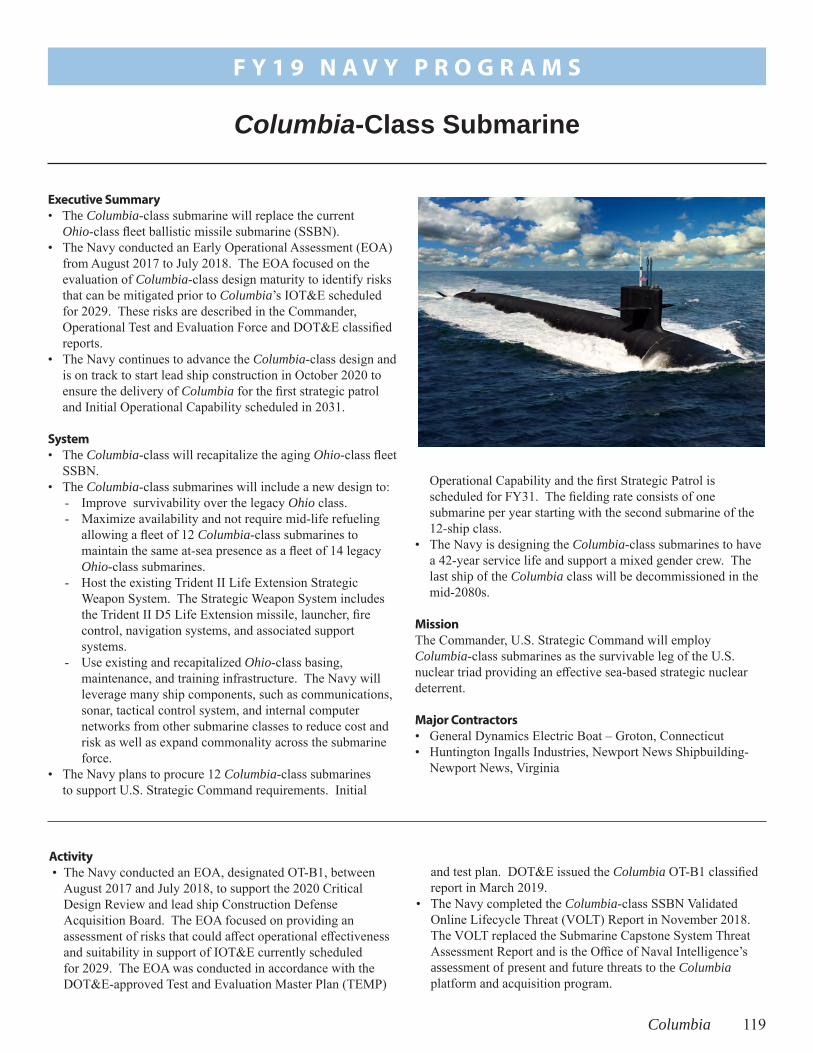
Columbia 119
and test plan. DOT&E issued the Columbia OT-B1 classified report in March 2019.
• The Navy completed the Columbia-class SSBN Validated Online Lifecycle Threat (VOLT) Report in November 2018. The VOLT replaced the Submarine Capstone System Threat Assessment Report and is the Office of Naval Intelligence’s assessment of present and future threats to the Columbia platform and acquisition program.
Activity • The Navy conducted an EOA, designated OT-B1, between
August 2017 and July 2018, to support the 2020 Critical Design Review and lead ship Construction Defense Acquisition Board. The EOA focused on providing an assessment of risks that could affect operational effectiveness and suitability in support of IOT&E currently scheduled for 2029. The EOA was conducted in accordance with the DOT&E-approved Test and Evaluation Master Plan (TEMP)
Operational Capability and the first Strategic Patrol is scheduled for FY31. The fielding rate consists of one submarine per year starting with the second submarine of the 12-ship class.
• The Navy is designing the Columbia-class submarines to have a 42-year service life and support a mixed gender crew. The last ship of the Columbia class will be decommissioned in the mid-2080s.
Mission The Commander, U.S. Strategic Command will employ Columbia-class submarines as the survivable leg of the U.S. nuclear triad providing an effective sea-based strategic nuclear deterrent.
Major Contractors• General Dynamics Electric Boat – Groton, Connecticut• Huntington Ingalls Industries, Newport News Shipbuilding-
Newport News, Virginia
Executive Summary • The Columbia-class submarine will replace the current
Ohio-class fleet ballistic missile submarine (SSBN).• The Navy conducted an Early Operational Assessment (EOA)
from August 2017 to July 2018. The EOA focused on the evaluation of Columbia-class design maturity to identify risks that can be mitigated prior to Columbia’s IOT&E scheduled for 2029. These risks are described in the Commander, Operational Test and Evaluation Force and DOT&E classified reports.
• The Navy continues to advance the Columbia-class design and is on track to start lead ship construction in October 2020 to ensure the delivery of Columbia for the first strategic patrol and Initial Operational Capability scheduled in 2031.
System • The Columbia-class will recapitalize the aging Ohio-class fleet
SSBN. • The Columbia-class submarines will include a new design to:
- Improve survivability over the legacy Ohio class.- Maximize availability and not require mid-life refueling
allowing a fleet of 12 Columbia-class submarines to maintain the same at-sea presence as a fleet of 14 legacy Ohio-class submarines.
- Host the existing Trident II Life Extension Strategic Weapon System. The Strategic Weapon System includes the Trident II D5 Life Extension missile, launcher, fire control, navigation systems, and associated support systems.
- Use existing and recapitalized Ohio-class basing, maintenance, and training infrastructure. The Navy will leverage many ship components, such as communications, sonar, tactical control system, and internal computer networks from other submarine classes to reduce cost and risk as well as expand commonality across the submarine force.
• The Navy plans to procure 12 Columbia-class submarines to support U.S. Strategic Command requirements. Initial
Columbia-Class Submarine
F Y 1 9 N A V Y P R O G R A M S

120 Columbia
F Y 1 9 N A V Y P R O G R A M S
• The Navy conducted two live fire test series in 2019 to support the survivability assessment of the vessel to underwater shock events. The first test series included shallow submergence underwater explosion tests to understand the response of representative scaled Tube Stiffened Models (TSM) when subjected to underwater shock loading. The second test series, using data from the first test series, included firings of small explosive charges against TSM’s inside a pressure vessel simulating a submerged environment. Both test series will improve the confidence in the modeling and simulation (M&S) used to assess the Columbia-class’s survivability. Tests were completed in accordance with the DOT&E-approved LFT&E Management Plan and detailed test plans.
• The Navy started the construction of all six Columbia-class super modules and is on track to meet Initial Operational Capability in 2031.
• In coordination with DOT&E, the Navy canceled the TEMP and LFT&E Management Plan update for 2019 as none were needed.
Assessment • The Columbia EOA identified several design risks that may
affect the ship’s operational effectiveness and suitability. The details are classified and can be found in the Commander,
Operational Test and Evaluation Force and DOT&E classified reports. The Program Office had identified many of these risks prior to the 2018 EOA and has plans to mitigate them prior to the start of Columbia’s IOT&E in 2029.
• The 2018 Columbia EOA addressed M&S limitations identified in the 2013 Ohio Replacement EOA and revealed additional, albeit known M&S limitations. The Columbia- and Virginia-class programs are collaborating to update the M&S for future operational assessments and IOT&E.
• DOT&E will continue to work with the Navy to secure test resources needed to evaluate Columbia’s susceptibility against emerging threats identified by the Intelligence Community as relevant to the effectiveness and survivability of the Columbia-class submarine program.
• Evaluation of the Columbia-class’s survivability to underwater threats was assessed in the first Columbia Survivability Assessment Report in February 2018. Additional analysis is ongoing and the next Columbia-class submarine Survivability Assessment Report is expected in 2026, prior to lead ship delivery from the shipyard.
Recommendation
1. The Navy should address the recommendations from the classified EOA reports.

CEC 121
Document (CDD) for CEC Increment II. The CDD identifies the required capabilities for future Increment II versions of CEC and reflects both increased threshold requirements and the introduction of new capabilities relative to CEC Increment I.
Assessment• Preliminary test results indicate the USG-3B AN/CEC, as
integrated with the E-2D, may have improved suitability
Activity• OPTEVFOR continued FOT&E of the CEC AN/USG-3B in
June 2019. • Not all the testing listed in the DOT&E-approved test plan was
completed, and there is no scheduled test period to compete the testing.
• The Navy does not have a plan to conduct cyber survivability testing for the AN/USG-3B.
• In FY19, the Assistant Deputy Chief of Naval Operations for Information Warfare developed a Capability Development
• CEC increases Naval Air Defense capabilities by integrating sensors and weapon assets into a single, real-time network that:- Expands the battlespace- Enhances situational awareness- Increases depth-of-fire- Enables longer intercept ranges- Improves decision and reaction times
MissionNaval Commanders employ platforms equipped with CEC to:• Improve battle force air and missile defense capabilities by
combining data from multiple battle force air search sensors on CEC-equipped units into a single, real-time, composite track picture.
• Provide accurate air and surface threat tracking data to ships equipped with the Ship Self-Defense System.
Major ContractorRaytheon Integrated Defense Systems Co. – St. Petersburg, Florida
Executive Summary• The Navy Commander, Operational Test and Evaluation
Force (OPTEVFOR) continued FOT&E of the Cooperative Engagement Capability (CEC) AN/USG-3B. Preliminary test results indicate that the AN/USG-3B CEC, as integrated with the E-2D Advanced Hawkeye, may have improved suitability compared to previously tested versions and that some previously reported deficiencies have been corrected.
• DOT&E will provide assessments of the CEC AN/USG-3B operational effectiveness and suitability in FY20.
• The Navy developed requirements for the future CEC Increment II and should submit a Test and Evaluation Master Plan (TEMP) for DOT&E approval.
System• CEC is a real-time sensor-netting system that enables
high-quality situational awareness and integrated fire control capability.
• There are four major U.S. Navy variants of CEC:- The AN/USG-2/2A is installed on select Aegis cruisers
and destroyers, San Antonio (LPD 17)-class and LHD amphibious ships, and Nimitz (CVN 68)-class aircraft carriers.
- The AN/USG-2B, an improved version of the AN/USG-2/2A, is installed or planned to be installed on CVN 68 and Gerald R. Ford (CVN 78)-class aircraft carriers, Zumwalt (DDG 1000)-class destroyers, selected Aegis cruisers/destroyers, and selected amphibious assault ships.
- The AN/USG-3 is installed on the E-2C Hawkeye 2000 aircraft.
- The AN/USG-3B is installed on the E-2D Advanced Hawkeye aircraft.
• The two major hardware components are the Cooperative Engagement Processor, which collects and fuses sensor data; and the Data Distribution System, which exchanges data between participating CEC units.
Cooperative Engagement Capability (CEC)
F Y 1 9 N A V Y P R O G R A M S

122 CEC
F Y 1 9 N A V Y P R O G R A M S
compared to previously tested versions and that some previously reported deficiencies have been corrected.
• DOT&E will provide assessments of the CEC AN/USG-3B operational effectiveness and suitability in FY20.
RecommendationsThe Navy should:
1. Conduct the DOT&E-approved testing not completed during FOT&E.
2. Plan and conduct cyber survivability testing on the CEC AN/USG-3B.
3. Submit to DOT&E, for approval, a revised CEC TEMP that describes the test strategy for CEC Increment II.

CVN 78 123
CVN 78 SDTS operational test events and has not resourced the remaining testing. If the Navy does not conduct all of the remaining events, testing will not be adequate to assess the operational effectiveness of the CVN 78 combat system.
• CVN 78 exhibits more electromagnetic compatibility problems than other Navy ships. The Navy continues to characterize the problems and develop mitigation plans.
• The development and testing of AWE, Electromagnetic Aircraft Launch System (EMALS), Advanced Arresting Gear (AAG), Dual Band Radar (DBR), and the Integrated Warfare System will continue to drive the CVN 78 timeline as it progresses toward IOT&E.
• The Navy continues to conduct the LFT&E program to provide the data and analyses required for the evaluation of the survivability of the ship to operationally significant threats.
System• The CVN 78 Gerald R. Ford-class aircraft carrier program
introduces a new class of nuclear-powered aircraft carriers. It uses the same hull form as the CVN 68 Nimitz-class but introduces a multitude of new ship systems.
• The new nuclear power plant reduces manning levels by 50 percent compared to a Nimitz-class ship and produces significantly more electricity. CVN 78 uses the increased electricity (instead of steam) to power electromagnetic catapults and AAG, both designed to increase reliability and expand the aircraft launch and recovery envelopes.
• The Navy redesigned weapons elevators, handling spaces, and stowage to reduce manning, improve safety, and increase weapon throughput. Weapon elevators utilize electromagnetic linear induction motors instead of cable driven systems.
• CVN 78 incorporates a more efficient flight deck layout, dedicated weapons handling areas, and an increased number of aircraft refueling stations designed to enhance its ability to launch, recover, and service aircraft.
Executive Summary• The DOT&E assessment of CVN 78 remains consistent
with previous assessments. Poor or unknown reliability of systems critical for flight operations, including newly designed catapults, arresting gear, weapons elevators, and radar, could affect the ability of CVN 78 to generate sorties. Reliability of these critical subsystems poses the most significant risk to the CVN 78 IOT&E timeline.
• CVN 78 entered the shipyard for a Post-Shakedown Availability (PSA)/Selected Restricted Availability (SRA) in July 2018 after completing eight Independent Steaming Event at-sea periods. The Navy originally planned a 1-year PSA, but extended it by 3 months to effect repairs until October 2019. The delays are due to the volume of work in the PSA, repairs and changes made to the propulsion plant based on lessons learned during sea trials, and acceptance delays for the Advanced Weapons Elevators (AWE).
• CVN 78 is unlikely to achieve the Sortie Generation Rate (SGR) (number of aircraft sorties per day) requirement. Unrealistic assumptions underpin the SGR threshold requirement. These assumptions ignore the effects of weather, aircraft emergencies, ship maneuvers, and current Air Wing composition on flight operations. DOT&E plans to assess CVN 78 performance during IOT&E by comparing it to the demonstrated performance of the Nimitz-class carriers, as well as to the SGR requirement.
• Because CVN 78 has been in the shipyard for PSA, the Navy does not have additional data from shipboard operations. Consequently, the Navy has not updated the reliability estimates for the catapults, arresting gear, radar, or weapons elevators.
• CVN 78 will likely be short of berthing spaces. Reduced manning requirements drove the design of CVN 78. The berthing capacity is 4,660; 1,100 fewer than Nimitz-class carriers. Manning requirements for new technologies, such as catapults, arresting gear, radar, and elevators are not well understood. Some of these concerns required redesignating some berthing areas and may require altering standard manpower strategies to achieve mission accomplishment. Recent estimates of expected combined manning of CVN 78, its Air Wing, embarked staffs, and detachments range from 4,656 to 4,758. The estimates do not include Service Life Allowance for future crew growth.
• The Navy conducted developmental and operational tests on the Self-Defense Test Ship (SDTS) that revealed combat system deficiencies and limitations associated with the SLQ-32(V)6 electronic warfare system, the SPY-3 Multi-Function Radar (MFR), and the Cooperative Engagement Capability (CEC). These deficiencies and limitations reduce the overall self-defense capability of the ship. The Navy has conducted only one of the four planned
CVN 78 Gerald R. Ford-Class Nuclear Aircraft Carrier
F Y 1 9 N A V Y P R O G R A M S

124 CVN 78
F Y 1 9 N A V Y P R O G R A M S
• CVN 78 includes a new Heavy underway replenishment system capable of transferring cargo loads of up to 12,000 pounds. Currently, only one supply ship, the USNS Arctic, has the Heavy replenishment system installed. The Navy has no current plans to include the system on other ships.
• The Navy intends to achieve CVN 78 Initial Operational Capability in FY21 prior to the start of Full Ship Shock Trial (FSST) and Full Operational Capability in FY24 after successful completion of IOT&E and Type Commander certification.
MissionCarrier Strike Group Commanders will use CVN 78 to:• Conduct power projection and strike warfare missions using
embarked aircraft• Provide force and area protection • Provide a sea base as both a command and control platform
and an air-capable unit
Major ContractorHuntington Ingalls Industries, Newport News Shipbuilding – Newport News, Virginia
• The CVN 78 combat system incorporates changes intended to improve upon the legacy Nimitz-class combat system. It consists of:- A phased-array DBR comprised of the SPY-4 Volume
Search Radar and the SPY-3 MFR. The DBR replaced several legacy radars used on current carriers for self-defense and air traffic control.
- Ship Self-Defense System (SSDS) Mark 2 command decision system
- CEC tracking and data fusion and distribution system - Surface Electronic Warfare Improvement Program
(SEWIP) Block 2-equipped SLQ-32(V)6 electronic surveillance system
- Rolling Airframe Missile (RAM) Block 2 and Evolved Sea Sparrow Missile (ESSM) Block 1
- Phalanx Close-In Weapon System• The ship includes the following enhanced survivability
features:- Improved protection for magazines and other vital spaces - Shock-hardened mission systems/components - Installed and portable damage control, firefighting, and
dewatering systems intended to expedite response to and recovery from peacetime fire, flooding, and battle damage
Activity • The Navy updated the Test and Evaluation Master Plan
(TEMP) 1610 and it is currently in the Navy approval chain. This TEMP continues two back-to-back phases of initial operational testing described in previous annual reports. The first phase focuses on routine unit-level operations and the ship’s internal workings (including cyclic flight operations with an embarked Air Wing) and culminates with successful completion of Composite Training Unit Exercise. Phase two focuses on more complex evolutions, including tests of the integrated combat system in self-defense scenarios, and includes integrated operations with an embarked Air Wing, Destroyer Squadron, and Carrier Strike Group staffs during the Composite Training Unit Exercise (COMPTUEX) at-sea period.
• The development, installation, and delivery of the AWE remains behind schedule. As of October 2019, CVN 78 has all 11 elevators installed but the Navy has only accepted 4. EMALS• The Navy expects to complete the EMALS Aircraft Launch
Bulletins (ALB), required for shipboard operations, for the C-2A, E-2C/D, F/A-18E/F, E/A-18G, and T-45C by the end of October 2019.
AAG• Aircraft Recovery Bulletins (ARB) for C-2A, E-2C/D,
F/A-18E/F, and E/A-18G were released August 2, 2019. These bulletins are required for shipboard flight operations with fleet aircraft.
• The Navy expects to complete the remaining AAG ARB, required for shipboard operations, by the end of
December 2019. The Barricade ARB completed October 4, 2019, and will be released with the T-45C ARB, which will be completed by the end of December 2019.
Combat System• In June 2019, the Navy conducted one of the four planned
CVN 78 operational tests planned for FY19 on the SDTS. However, the remaining three tests are unlikely to be conducted in accordance with the DOT&E-approved CVN 78 data collection plan, the DOT&E-approved Capstone Enterprise Air Warfare Ship Self-Defense TEMP, and the DOT&E-approved SSDS TEMP. The Navy canceled one test event because they did not incorporate software changes required to conduct the test on the SDTS and the event was not resourced. The Navy delayed another test event due to poor SLQ-32(V)6 performance in developmental testing. The final, most challenging test event planned for 2QFY20 is not currently funded. The Navy may have to cancel the remaining delayed/unfunded events if they are not conducted before the MFR is removed from the SDTS; this removal is currently planned for the end of 2QFY20. If the Navy does not conduct all of the remaining events, testing will not be adequate to assess the operational effectiveness of the CVN 78 combat system.
• The Navy has not resourced combat system testing on the lead ship or the modeling and simulation (M&S) required to support evaluation of the ship’s Probability of Raid Annihilation (PRA) requirement.
F Y 1 9 N A V Y P R O G R A M S
CVN 78 125
Live Fire Test & Evaluation• The Navy continued planning of the CVN 78 Full Ship
Shock Trial (FSST), including shock trial logistics, environmental requirements, instrumentation, and related analyses. Due to the extended PSA, the Navy intends to conduct the FSST in FY21.
• The Navy continues work on survivability assessments of the CVN 78 design against weapon threats using M&S-based vulnerability analysis and scenario-based recoverability assessments.
Assessment • As noted in previous annual reports, the test schedule has
been aggressive. This year, the planned schedule slipped over a year. The recent extension in Planned Ship Availability delayed both phases of initial operational testing until FY22, and pushed the ship’s first deployment to FY23. Reliability• Four of CVN 78’s new systems stand out as being critical
to flight operations: EMALS, AAG, DBR, and AWE. Overall, the poor reliability demonstrated by AAG and EMALS and the uncertain reliability of DBR and AWE could further delay CVN 78 IOT&E. Reliability estimates derived from test data for EMALS and AAG are discussed in following subsections. Since CVN 78 spent FY19 in the shipyard for PSA, the Navy has not conducted additional aircraft launches or recoveries from the ship. For DBR and AWE, only engineering reliability estimates have been provided.
EMALS • Through the first 747 shipboard launches, EMALS suffered
10 critical failures. This is well below the requirement for Mean Cycles Between Critical Failures, where a cycle represents the launch of one aircraft. The Navy identified 9 unique Incident Reports (IRs) that resulted in the 10 critical failures for EMALS. Of the nine IRs, one fix was installed during PSA and is in place to support flight operations during CVN 78’s Post Delivery Test and Trials (PDT&T). Four IRs will be corrected commencing in late FY20. The four remaining IRs occurred only once during pre-PSA operations, are deemed low priority, and will be monitored during future flight operations.
• The reliability concerns are exacerbated by the fact that the crew cannot readily electrically isolate EMALS components during flight operations due to the shared nature of the Energy Storage Groups and Power Conversion Subsystem inverters on board CVN 78. The process for electrically isolating equipment is time-consuming; spinning down the EMALS motor/generators takes 1.5 hours by itself. The inability to readily electrically isolate equipment precludes EMALS maintenance during flight operations.
AAG• The Program Office redesigned major components that did
not meet system specifications during land-based testing. Through the first 747 attempted shipboard landings, AAG suffered 10 operational mission failures, including one
incident to the engine that supports the barricade. The Navy identified 7 unique IRs that caused the 10 operational mission failures for AAG. Of the seven, six fixes have been installed and will be in place to support flight operations during CVN 78’s PDT&T. The one remaining IR occurred once, is deemed low priority, and will be monitored during future flight operations.
• This reliability estimate falls well below the re-baselined reliability growth curve and well below the requirement for Mean Cycles Between Operational Mission Failures, where a cycle represents the recovery of one aircraft.
• The reliability concerns are magnified by the current AAG design that does not allow electrical isolation of the Power Conditioning Subsystem equipment from high power buses, limiting corrective maintenance on below-deck equipment during flight operations.
Combat System• The CVN 78 SDTS events revealed good performance
of the SSDS Mark 2 command decision system due to its ability to manage the combat system tracks, manage and apply the ship’s engagement doctrine, and schedule intercepts and launch missiles against incoming subsonic anti-ship cruise missile (ASCM) surrogates.
• In the most recent CVN 78 SDTS developmental test event, the MFR and CEC failed to maintain detections and tracks for one of the threat surrogates in the multi-target raid; however, that raid presented a scenario that was more challenging to the combat system than originally planned.
• In developmental testing on SDTS, the SLQ-32(V)6 electronic surveillance system demonstrated poor performance that prompted the Navy to delay additional operational tests until those problems could be corrected. Similar problems were previously reported in DOT&E’s September 2016 SLQ-32(V)6 SEWIP Block 2 IOT&E Report.
• The Navy continues to address known deficiencies with the DBR Air Traffic Control (ATC), but the resolution of those problems will not be known until CVN 78 returns to sea. In at-sea testing before the PSA, DBR was plagued by extraneous false and close-in dual tracks adversely affecting ATC performance, and Navy analysis noted that DBR performance needs to be improved to support carrier ATC center certification.
SGR• CVN 78 is unlikely to achieve its SGR requirement.
The target threshold is based on unrealistic assumptions including fair weather and unlimited visibility, and that aircraft emergencies, failures of shipboard equipment, ship maneuvers, and manning shortfalls will not affect flight operations. During the 2013 operational assessment, DOT&E conducted an analysis of past aircraft carrier operations in major conflicts. The analysis concludes that the CVN 78 SGR requirement is well above historical levels.
• DOT&E plans to assess CVN 78 performance during IOT&E by comparing it to the SGR requirement, as well

F Y 1 9 N A V Y P R O G R A M S
126 CVN 78
as to the demonstrated performance of the Nimitz-class carriers.
• Poor reliability of key systems that support sortie generation on CVN 78 could cause a cascading series of delays during flight operations that would affect CVN 78’s ability to generate sorties. The poor or unknown reliability of these critical subsystems represents the most risk to the successful completion of CVN 78 IOT&E.
Manning• Based on current expected manning, the berthing capacity
for officers and enlisted will be exceeded by approximately 100 personnel with some variability in the estimates. This also leaves no room for extra personnel during inspections, exercises, or routine face-to-face turnovers.
• Planned ship manning requires filling 100 percent of the billets. This is not the Navy’s standard practice on other ships, and the personnel and training systems may not be able to support 100 percent manning. Additionally, workload estimates for the many new technologies, such as catapults, arresting gear, radar, and weapons and aircraft elevators are not yet well understood.
Electromagnetic Compatibility• Developmental testing identified significant electromagnetic
radiation hazard and interference problems. The Navy continues to characterize and develop mitigation plans for the problems, but some operational limitations and restrictions are expected to persist into IOT&E and deployment. The Navy will need to develop capability assessments at differing levels of system utilization in order for commanders to make informed decisions on system employment.
Live Fire Test & Evaluation• The potential vulnerability of CVN 78’s new critical
systems to underwater threat-induced shock has not yet
been fully characterized. The program continued shock testing on EMALS, AAG, and the AWE components during CY19 but because of a scarcity of systems, alternatives to component shock testing of DBR components are being pursued and shock testing will likely not be completed before the FSST. The Vulnerability Assessment Reports delivered to date provide an assessment of the ship’s survivability to air-delivered threat engagements. The classified findings in the report identify the specific equipment that most frequently would lead to mission capability loss. In FY20, the Navy is scheduled to deliver additional report volumes that will assess vulnerability to underwater threats and compliance with Operational Requirements Document survivability criteria.
RecommendationsThe Navy should:
1. Continue to characterize the electromagnetic environment on board CVN 78 and develop operating procedures to maximize system effectiveness and maintain safety. As applicable, the Navy should utilize the lessons learned from CVN 78 to inform design modifications for CVN 79 and future carriers.
2. Fund all remaining SDTS events and explore the possibility of leaving the MFR on the SDTS past 2QFY20 to allow for completion of the CVN 78 self-defense test program.
3. Fund the CVN 78 lead ship combat system operational testing and the M&S required to support assessment of the CVN 78 PRA requirement.
4. Implement the required software updates to multiple combat system elements to allow cueing from external sources necessary to conduct one of the SDTS test events.

DAIRCM 127
• The Navy plans to incorporate data from the DAIRCM digital system model to expand the set of performance data for system performance evaluations.
Assessment Preliminary results indicate the DAIRCM system as installed on the MH-60S and AH-1Z helicopters has the capability to defeat:• Vehicle-launched, infrared-guided missiles and MANPADS• Laser-guided threats and hostile fire
Recommendation1. The Navy should complete the verification and validation
of the missile warning digital system model.
Activity • The Navy completed laser warning and hostile fire testing
using a surrogate target at the Naval Air Warfare Center’s Weapons Survivability Laboratory located in China Lake, California, from August to September 2019 to support the Navy’s Quick Reaction Assessment (QRA).
• The Navy completed the first phase of missile warning testing using the MH-60S and the AH-1Z helicopters at Hot Springs, Virginia, in August 2019 to support the Navy’s QRA.
• The Navy began conducting the second phase of missile warning testing in September 2019 using the MH-60S and AH-1Z helicopters at Eglin AFB, Florida, to support the Navy’s QRA.
• The Navy completed VMX-1 Maintainer and Operator Training in Yuma, Arizona, from April to May 2019.
evacuation, search and rescue, armed escort, and attack operations.
• During missions, the DAIRCM system is intended to provide automatic protection for rotary-wing aircraft against shoulder-fired, vehicle-launched, and other infrared-guided missiles.
Major Contractors• Leonardo Digital/Retrieval Systems (DRS) Infrared Sensors
and Systems – Dallas, Texas• Leonardo DRS Daylight Solutions – San Diego, California
Executive SummaryPreliminary results from Navy testing indicate the Distributed Aperture Infrared Countermeasures (DAIRCM) system as installed on the MH-60S and AH-1Z helicopters has the capability to defeat vehicle-launched infrared-guided missiles and man-portable air-defense systems (MANPADS). The DAIRCM system has the capability to detect laser-guided threats and hostile fire near the MH-60S and AH-1Z helicopters.
System• The DAIRCM system is an integrated suite of missile
warning, laser warning, hostile fire indicator, and infrared countermeasure components designed to protect rotary-wing aircraft from the threat posed by infrared missiles.
• The system uses a single, centrally installed laser that can feed all of the beam directors. The threat warning sensor sends raw video and digital data information to the processor, which analyzes the data for an incoming Missile, Laser, or Hostile Fire threat. If the processor detects a threat, it notifies the aircrew through the control interface unit and initiates the laser to direct jamming energy at the incoming missile, if applicable.
• The Navy’s Program Office for Advanced Tactical Aircraft Protection Systems, PMA-272, is the lead for developing the DAIRCM system.
Mission• Commanders employ rotorcraft equipped with the DAIRCM
system to conduct medium lift logistical support, medical
Distributed Aperture Infrared Countermeasure System (DAIRCM)
F Y 1 9 N A V Y P R O G R A M S

128
F Y 1 9 N A V Y P R O G R A M S
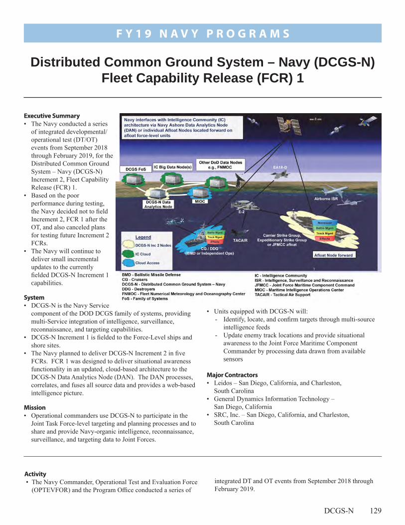
DCGS-N 129
• Units equipped with DCGS-N will:- Identify, locate, and confirm targets through multi-source
intelligence feeds- Update enemy track locations and provide situational
awareness to the Joint Force Maritime Component Commander by processing data drawn from available sensors
Major Contractors• Leidos – San Diego, California, and Charleston,
South Carolina• General Dynamics Information Technology –
San Diego, California• SRC, Inc. – San Diego, California, and Charleston,
South Carolina
Executive Summary• The Navy conducted a series
of integrated developmental/operational test (DT/OT) events from September 2018 through February 2019, for the Distributed Common Ground System – Navy (DCGS-N) Increment 2, Fleet Capability Release (FCR) 1.
• Based on the poor performance during testing, the Navy decided not to field Increment 2, FCR 1 after the OT, and also canceled plans for testing future Increment 2 FCRs.
• The Navy will continue to deliver small incremental updates to the currently fielded DCGS-N Increment 1 capabilities.
System• DCGS-N is the Navy Service
component of the DOD DCGS family of systems, providing multi-Service integration of intelligence, surveillance, reconnaissance, and targeting capabilities.
• DCGS-N Increment 1 is fielded to the Force-Level ships and shore sites.
• The Navy planned to deliver DCGS-N Increment 2 in five FCRs. FCR 1 was designed to deliver situational awareness functionality in an updated, cloud-based architecture to the DCGS-N Data Analytics Node (DAN). The DAN processes, correlates, and fuses all source data and provides a web-based intelligence picture.
Mission• Operational commanders use DCGS-N to participate in the
Joint Task Force-level targeting and planning processes and to share and provide Navy-organic intelligence, reconnaissance, surveillance, and targeting data to Joint Forces.
Distributed Common Ground System – Navy (DCGS-N) Fleet Capability Release (FCR) 1
F Y 1 9 N A V Y P R O G R A M S
integrated DT and OT events from September 2018 through February 2019.
Activity • The Navy Commander, Operational Test and Evaluation Force
(OPTEVFOR) and the Program Office conducted a series of

130 DCGS-N
F Y 1 9 N A V Y P R O G R A M S
- OPTEVFOR conducted a Cooperative Vulnerability and Penetration Assessment at the Naval Information Warfare Center – Pacific (NIWC-PAC), September 24 – 28, 2018.
- OPTEVFOR and the Program Office conducted an integrated DT/OT event in the NIWC-PAC laboratory, October 16 – 21, 2018.
- OPTEVFOR conducted integrated DT/OT at the Commander, Fourth Fleet Maritime Information Operations Center, January 21 – 24, 2019.
- The OPTEVFOR cybersecurity test team conducted an Adversarial Assessment at NIWC-Atlantic, February 4 – 8, 2019.
• DOT&E published the DCGS-N FCR 1 operational test report on August 16, 2019.
• Based on the poor performance of FCR 1 during testing, the Navy decided not to deploy FCR 1. The Navy also stopped test planning for FCR 2. The Navy plans to continue integrating updated technologies to Increment 1 in small increments.
• The Navy is working to update the acquisition strategy and the Test and Evaluation Master Plan.
Assessment• DCGS-N FCR 1 could not perform the required functions
during the integrated test events.• The agile testing process did not adequately test external
interfaces. The DT strategy worked as designed and identified critical data integrity shortfalls with the interfacing systems providing air and sea tracks. However, the test schedule did not include the time to fix major performance shortfalls between DT and OT.
• OT was adequate to inform the acquisition decision-makers.
Recommendation1. The Navy should continue to work with DOT&E to conduct
adequate testing of DCGS-N updates.

E-2D 131
Assessment • Aerial Refueling brings the E-2D a dramatic increase in
operational range, endurance, and safety at sea. The Aerial Refueling flight clearance met testing requirements; however, expanding the operational Aerial Refueling flight clearance envelope would give operational commanders more flexibility at sea.
• Following testing, the Navy concluded DSSC-3 met the naval requirements for NIFC capabilities. DOT&E notes that preliminary operational test results demonstrated a significant increase in NIFC capabilities. DOT&E will provide its assessment in 2QFY20.
Activity • DOT&E approved the Test Evaluation Master Plan (TEMP)
Revision E in January 2019 in support of the third FOT&E period (OT-D3). The test focused on Aerial Refueling and various upgrades and enhancements to the E-2D and system of systems.
• The Navy submitted the OT-D3 test plan, which DOT&E approved in 2QFY19. In 4QFY19, VX-1 completed operational flight test of DSSC-3 in accordance with the DOT&E-approved TEMP and test plan.
• During March, April, and August, the Navy operationally tested E-2D DSSC-3, F/A-18 E/F/G, Infrared Search and Track Block 1 AV6+, LRASM, and NIFC at the same time.
• The Navy intends to conduct cybersecurity testing in 1QFY20.
• The E-2D Advanced Hawkeye Program includes all simulators, interactive computer media, and documentation to conduct maintenance, as well as aircrew shore-based initial and follow-on training.
• DSSC-3 included the Automated Identification System, Mode 5 Interrogator, Embedded National Tactical Receiver, Automatic Dependent Surveillance-Broadcast, Accelerated Mid-Term Interoperability Improvement Program, Integrated Fire Control improvements, and the introduction of Aerial Refueling.
MissionThe Combatant Commander, whether operating from the aircraft carrier or from land, will use the E-2D Advanced Hawkeye to accomplish the following missions:• Theater air and missile detection and early warning• Battlefield management, command, and control• Acquisition, tracking, and targeting of surface warfare contacts• Surveillance of littoral area objectives and targets• Tracking of strike warfare assets
Major ContractorNorthrop Grumman Aerospace Systems – Melbourne, Florida
Executive Summary• The Navy conducted E-2D operational testing for Delta
System/Software Configuration (DSSC)-Build 3 and Aerial Refueling upgrades throughout 2019.
• The E-2D demonstrated operational Aerial Refueling as a receiver for the first time.
• Operational performance of Naval Integrated Fire Control (NIFC) capabilities in DSSC-3 improved over previous software versions as validated by successful end-to-end live fire testing.
• The Navy increased test efficiency by simultaneously operationally testing E-2D DSSC-3, F/A-18E/F/G, Infrared Search and Track Block 1 AV6+, Long Range Anti-Ship Missile (LRASM), and NIFC.
• DSSC-3 specific operational cybersecurity testing has not been completed.
System• The E-2D Advanced Hawkeye is a carrier-based airborne early
warning and command and control aircraft.• Significant changes to this variant of the E-2 include:
upgraded engines to provide increased electrical power and cooling relative to current E-2C aircraft; a strengthened fuselage to support increased aircraft weight; replacement of the radar system, communications suite, and mission computer; and incorporation of an all-glass cockpit, which permits the co-pilot to act as a tactical fourth operator in support of the system operators in the rear of the aircraft.
• The radar upgrade replaces the E-2C mechanically scanned radar with a phased-array radar that has combined mechanical and electronic scan capabilities.
• The upgraded radar is designed to improve littoral and overland detection performance and Theater Air and Missile Defense capabilities.
E-2D Advanced Hawkeye
F Y 1 9 N A V Y P R O G R A M S

132 E-2D
F Y 1 9 N A V Y P R O G R A M S
• Preliminary OT-D3 data and observation support the previous DOT&E assessment that radar reliability and aircraft availability demonstrated similar shortfalls to the IOT&E accomplished in 2006.
RecommendationsThe Navy should:
1. Conduct cybersecurity testing in accordance with DOT&E guidance.
2. Increase radar and aircraft reliability in order to improve aircraft availability.
3. Increase the operational Aerial Refueling flight clearance envelope to give operational commanders more flexibility at sea.
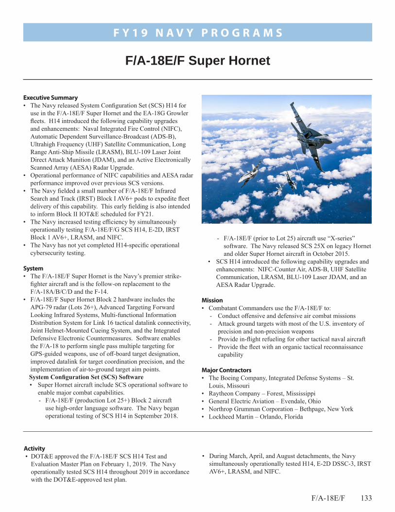
F/A-18E/F 133
• During March, April, and August detachments, the Navy simultaneously operationally tested H14, E-2D DSSC-3, IRST AV6+, LRASM, and NIFC.
Activity • DOT&E approved the F/A-18E/F SCS H14 Test and
Evaluation Master Plan on February 1, 2019. The Navy operationally tested SCS H14 throughout 2019 in accordance with the DOT&E-approved test plan.
- F/A-18E/F (prior to Lot 25) aircraft use “X-series” software. The Navy released SCS 25X on legacy Hornet and older Super Hornet aircraft in October 2015.
• SCS H14 introduced the following capability upgrades and enhancements: NIFC-Counter Air, ADS-B, UHF Satellite Communication, LRASM, BLU-109 Laser JDAM, and an AESA Radar Upgrade.
Mission• Combatant Commanders use the F/A-18E/F to:
- Conduct offensive and defensive air combat missions- Attack ground targets with most of the U.S. inventory of
precision and non-precision weapons- Provide in-flight refueling for other tactical naval aircraft- Provide the fleet with an organic tactical reconnaissance
capability
Major Contractors• The Boeing Company, Integrated Defense Systems – St.
Louis, Missouri• Raytheon Company – Forest, Mississippi• General Electric Aviation – Evendale, Ohio• Northrop Grumman Corporation – Bethpage, New York• Lockheed Martin – Orlando, Florida
Executive Summary• The Navy released System Configuration Set (SCS) H14 for
use in the F/A-18E/F Super Hornet and the EA-18G Growler fleets. H14 introduced the following capability upgrades and enhancements: Naval Integrated Fire Control (NIFC), Automatic Dependent Surveillance-Broadcast (ADS-B), Ultrahigh Frequency (UHF) Satellite Communication, Long Range Anti-Ship Missile (LRASM), BLU-109 Laser Joint Direct Attack Munition (JDAM), and an Active Electronically Scanned Array (AESA) Radar Upgrade.
• Operational performance of NIFC capabilities and AESA radar performance improved over previous SCS versions.
• The Navy fielded a small number of F/A-18E/F Infrared Search and Track (IRST) Block I AV6+ pods to expedite fleet delivery of this capability. This early fielding is also intended to inform Block II IOT&E scheduled for FY21.
• The Navy increased testing efficiency by simultaneously operationally testing F/A-18E/F/G SCS H14, E-2D, IRST Block 1 AV6+, LRASM, and NIFC.
• The Navy has not yet completed H14-specific operational cybersecurity testing.
System• The F/A-18E/F Super Hornet is the Navy’s premier strike-
fighter aircraft and is the follow-on replacement to the F/A-18A/B/C/D and the F-14.
• F/A-18E/F Super Hornet Block 2 hardware includes the APG-79 radar (Lots 26+), Advanced Targeting Forward Looking Infrared Systems, Multi-functional Information Distribution System for Link 16 tactical datalink connectivity, Joint Helmet-Mounted Cueing System, and the Integrated Defensive Electronic Countermeasures. Software enables the F/A-18 to perform single pass multiple targeting for GPS-guided weapons, use of off-board target designation, improved datalink for target coordination precision, and the implementation of air-to-ground target aim points.System Configuration Set (SCS) Software• Super Hornet aircraft include SCS operational software to
enable major combat capabilities. - F/A-18E/F (production Lot 25+) Block 2 aircraft
use high-order language software. The Navy began operational testing of SCS H14 in September 2018.
F/A-18E/F Super Hornet
F Y 1 9 N A V Y P R O G R A M S

134 F/A-18E/F
F Y 1 9 N A V Y P R O G R A M S
• During February and March 2019, the Navy completed a DOT&E-approved IRST AV6+ early fielding test.
• The Navy released SCS H14 to the F/A-18E/F and EA-18G fleets in 2019.
• The Navy fielded a small number of IRST Block I Low-Rate Initial Production II AV6+ systems in 2019.
• The Navy has not yet conducted comprehensive SCS H14 cybersecurity testing.
Assessment • As testing is still ongoing, DOT&E will include a full analysis
and assessment of SCS H14 in the classified operational test report in 2QFY20. However, DOT&E notes the following: - Operational performance of NIFC capabilities in SCS
H14 improved over previous SCS versions as validated by successful end-to-end live fire testing.
- H14 increased operational performance of the AESA radar over previous SCS versions. AESA reliability has continued to improve since the 2006 IOT&E.
• The IRST Block I AV6+ test demonstrated improvement over the baseline IRST Block I. The IRST Block I AV6+ crew vehicle interface improved over baseline IRST Block I. Testing in preparation for early fielding of a small number of pods has informed the operational test plan for IRST Block II.
• The Navy has yet to accomplish an end-to-end multiple AIM-120 missile test that successfully demonstrates the AESA can support this required capability.
RecommendationsThe Navy should:
1. Conduct the end-to-end testing employing multiple AIM-120 missiles.
2. Conduct a comprehensive SCS H14 cybersecurity operational test.
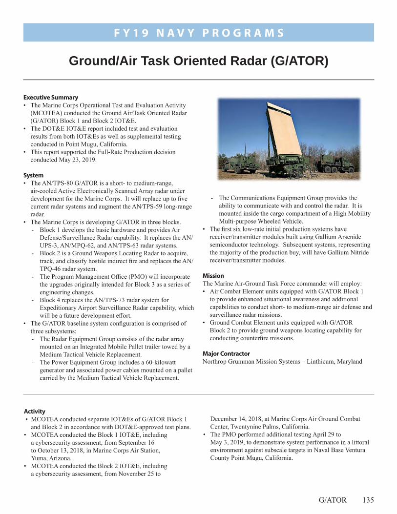
G/ATOR 135
December 14, 2018, at Marine Corps Air Ground Combat Center, Twentynine Palms, California.
• The PMO performed additional testing April 29 to May 3, 2019, to demonstrate system performance in a littoral environment against subscale targets in Naval Base Ventura County Point Mugu, California.
Activity • MCOTEA conducted separate IOT&Es of G/ATOR Block 1
and Block 2 in accordance with DOT&E-approved test plans.• MCOTEA conducted the Block 1 IOT&E, including
a cybersecurity assessment, from September 16 to October 13, 2018, in Marine Corps Air Station, Yuma, Arizona.
• MCOTEA conducted the Block 2 IOT&E, including a cybersecurity assessment, from November 25 to
- The Communications Equipment Group provides the ability to communicate with and control the radar. It is mounted inside the cargo compartment of a High Mobility Multi-purpose Wheeled Vehicle.
• The first six low-rate initial production systems have receiver/transmitter modules built using Gallium Arsenide semiconductor technology. Subsequent systems, representing the majority of the production buy, will have Gallium Nitride receiver/transmitter modules.
MissionThe Marine Air-Ground Task Force commander will employ: • Air Combat Element units equipped with G/ATOR Block 1
to provide enhanced situational awareness and additional capabilities to conduct short- to medium-range air defense and surveillance radar missions.
• Ground Combat Element units equipped with G/ATOR Block 2 to provide ground weapons locating capability for conducting counterfire missions.
Major ContractorNorthrop Grumman Mission Systems – Linthicum, Maryland
Executive Summary• The Marine Corps Operational Test and Evaluation Activity
(MCOTEA) conducted the Ground Air/Task Oriented Radar (G/ATOR) Block 1 and Block 2 IOT&E.
• The DOT&E IOT&E report included test and evaluation results from both IOT&Es as well as supplemental testing conducted in Point Mugu, California.
• This report supported the Full-Rate Production decision conducted May 23, 2019.
System• The AN/TPS-80 G/ATOR is a short- to medium-range,
air-cooled Active Electronically Scanned Array radar under development for the Marine Corps. It will replace up to five current radar systems and augment the AN⁄TPS-59 long-range radar.
• The Marine Corps is developing G/ATOR in three blocks.- Block 1 develops the basic hardware and provides Air
Defense/Surveillance Radar capability. It replaces the AN/UPS-3, AN/MPQ-62, and AN/TPS-63 radar systems.
- Block 2 is a Ground Weapons Locating Radar to acquire, track, and classify hostile indirect fire and replaces the AN/TPQ-46 radar system.
- The Program Management Office (PMO) will incorporate the upgrades originally intended for Block 3 as a series of engineering changes.
- Block 4 replaces the AN/TPS-73 radar system for Expeditionary Airport Surveillance Radar capability, which will be a future development effort.
• The G/ATOR baseline system configuration is comprised of three subsystems:- The Radar Equipment Group consists of the radar array
mounted on an Integrated Mobile Pallet trailer towed by a Medium Tactical Vehicle Replacement.
- The Power Equipment Group includes a 60-kilowatt generator and associated power cables mounted on a pallet carried by the Medium Tactical Vehicle Replacement.
Ground/Air Task Oriented Radar (G/ATOR)
F Y 1 9 N A V Y P R O G R A M S

136 G/ATOR
F Y 1 9 N A V Y P R O G R A M S
• The Assistant Secretary of the Navy for Research, Development and Acquisition conducted the Full-Rate Production decision on May 23, 2019.
Assessment Testing was adequate to determine system operational effectiveness, suitability, and survivability. However, the tests did not include all required types of targets or operational environments. Details and results are in the May 2019 classified DOT&E IOT&E report.
RecommendationsThe PMO and MCOTEA should:
1. Where feasible, conduct test, including concurrent test events, in operationally realistic environments to assess performance against all required types of targets.
2. Verify correction of deficiencies identified during IOT&E and reported in the May 2019 DOT&E IOT&E report.

JPALS 137
from October 2017 to March 2019 to support the Navy’s June 2018 EOC declaration.
Activity • OPTEVFOR completed IOT&E Phase I of JPALS Block 0
One-Way capability for F-35B/C aircraft approaches to aircraft carriers and amphibious assault ships. Testing was conducted
providing the accuracy, integrity, and continuity required for future F-35C and MQ-25A autoland capability on CVN-type ships and F-35B coupled flight capability on LH-type ships.
Mission• Operational Commanders will use units equipped with JPALS
Block 0 to achieve precision approach and landing capability for F-35B aircraft deployed to amphibious assault ships with minimal effect from conditions at point of departure or landing.
• Operational Commanders will use units equipped with JPALS Block 1 to achieve precision approach and landing capability for F-35B/C and MQ-25A for stand-alone or close-proximity air operations with CVN- and LH-type ships throughout the world.
Major Contractor Raytheon Network Centric Systems – Fullerton, California
Executive Summary• The Navy Commander, Operational Test
and Evaluation Force (OPTEVFOR) conducted IOT&E Phase I for the Joint Precision Approach and Landing System (JPALS) Block 0 One-Way capability from October 2017 to March 2019. This testing was conducted to support an Early Operational Capability (EOC) of JPALS for use with Fleet F-35B aircraft deployment to amphibious assault ships.
• DOT&E determined JPALS Block 0 One-Way capability is operationally effective and suitable for the Navy’s EOC.
• DOT&E approved the Milestone C Test and Evaluation Master Plan (TEMP) in March 2019.
• OPTEVFOR conducted operational testing aboard USS Dwight D. Eisenhower (CVN 69) in April 2019 to support the JPALS Block 1 Two-Way capability Operational Assessment (OA). During shipboard testing, pilots completed the requisite number of JPALS auto-piloted approaches and landings, with the plan to complete the OA in FY20.
• JPALS Block 1 Two-Way capability IOT&E Phase II planning is currently in progress.
System• JPALS is composed of modular open system hardware and
software components integrated with shipboard Air Traffic Control and landing system architectures for JPALS data display and functional operation.
• JPALS major subsystems include the GPS sensor, navigation processing, datalink, ship motion sensor, maintenance, and ship interface subsystems.
• JPALS Block 0 is an interim solution/EOC of JPALS, specifically to support the F-35B. Block 0 uses an ultrahigh frequency (UHF) One-Way datalink broadcast to transmit a subset of the JPALS precision approach data and on-deck Inertial Navigation System alignment from ship to aircraft.
• JPALS Block 1 will further support the F-35B/C and MQ-25A with an UHF Two-Way datalink broadcast capability by
Joint Precision Approach and Landing System (JPALS)
F Y 1 9 N A V Y P R O G R A M S

138 JPALS
F Y 1 9 N A V Y P R O G R A M S
• DOT&E approved the JPALS Milestone C TEMP in March 2019.
• OPTEVFOR conducted testing aboard USS Dwight D. Eisenhower (CVN 69) in the Virginia Capes Operating Area in April 2019 to support the JPALS Block 1 Two-Way capability OA. Testing was executed concurrently with developmental testing as part of an integrated test.
• Pilots completed 21 approaches, 14 of which included autonomous JPALS assisted landings.
• A modified F/A-18C served as a JPALS Test Bed as no fleet aircraft currently can use the JPALS Two-Way capability for precision approaches to fully automated JPALS assisted landings. Fielding of JPALS Two-Way capability is not expected until F-35 Block 4.3 in FY24.
• JPALS Block 1 Two-Way capability IOT&E Phase II planning is currently in progress.
• DOT&E will release separate reports for the IOT&E JPALS Block 0 One-Way Phase I and IOT&E Block 1 Two-Way Phase II.
• All testing was conducted in accordance with a DOT&E-approved TEMP.
Assessment JPALS Block 0 One-Way capability is operationally effective and suitable to support the Navy’s EOC.
Recommendation1. The JPALS Program Office should continue to coordinate
with the F-35 and MQ-25 Program Offices to integrate testing.
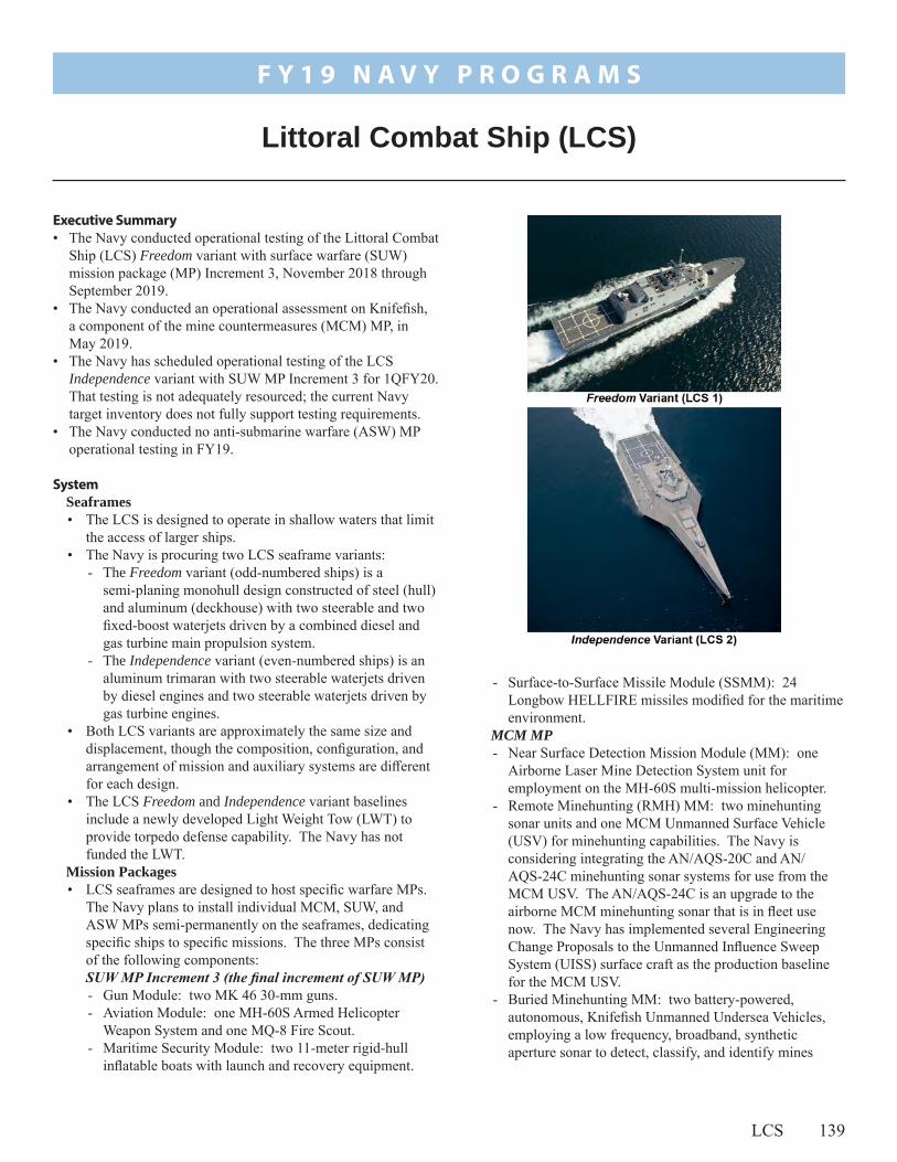
LCS 139
- Surface-to-Surface Missile Module (SSMM): 24 Longbow HELLFIRE missiles modified for the maritime environment.
MCM MP - Near Surface Detection Mission Module (MM): one
Airborne Laser Mine Detection System unit for employment on the MH-60S multi-mission helicopter.
- Remote Minehunting (RMH) MM: two minehunting sonar units and one MCM Unmanned Surface Vehicle (USV) for minehunting capabilities. The Navy is considering integrating the AN/AQS-20C and AN/AQS-24C minehunting sonar systems for use from the MCM USV. The AN/AQS-24C is an upgrade to the airborne MCM minehunting sonar that is in fleet use now. The Navy has implemented several Engineering Change Proposals to the Unmanned Influence Sweep System (UISS) surface craft as the production baseline for the MCM USV.
- Buried Minehunting MM: two battery-powered, autonomous, Knifefish Unmanned Undersea Vehicles, employing a low frequency, broadband, synthetic aperture sonar to detect, classify, and identify mines
Executive Summary• The Navy conducted operational testing of the Littoral Combat
Ship (LCS) Freedom variant with surface warfare (SUW) mission package (MP) Increment 3, November 2018 through September 2019.
• The Navy conducted an operational assessment on Knifefish, a component of the mine countermeasures (MCM) MP, in May 2019.
• The Navy has scheduled operational testing of the LCS Independence variant with SUW MP Increment 3 for 1QFY20. That testing is not adequately resourced; the current Navy target inventory does not fully support testing requirements.
• The Navy conducted no anti-submarine warfare (ASW) MP operational testing in FY19.
SystemSeaframes• The LCS is designed to operate in shallow waters that limit
the access of larger ships.• The Navy is procuring two LCS seaframe variants:
- The Freedom variant (odd-numbered ships) is a semi-planing monohull design constructed of steel (hull) and aluminum (deckhouse) with two steerable and two fixed-boost waterjets driven by a combined diesel and gas turbine main propulsion system.
- The Independence variant (even-numbered ships) is an aluminum trimaran with two steerable waterjets driven by diesel engines and two steerable waterjets driven by gas turbine engines.
• Both LCS variants are approximately the same size and displacement, though the composition, configuration, and arrangement of mission and auxiliary systems are different for each design.
• The LCS Freedom and Independence variant baselines include a newly developed Light Weight Tow (LWT) to provide torpedo defense capability. The Navy has not funded the LWT.
Mission Packages• LCS seaframes are designed to host specific warfare MPs.
The Navy plans to install individual MCM, SUW, and ASW MPs semi-permanently on the seaframes, dedicating specific ships to specific missions. The three MPs consist of the following components:SUW MP Increment 3 (the final increment of SUW MP) - Gun Module: two MK 46 30-mm guns. - Aviation Module: one MH-60S Armed Helicopter
Weapon System and one MQ-8 Fire Scout. - Maritime Security Module: two 11-meter rigid-hull
inflatable boats with launch and recovery equipment.
Littoral Combat Ship (LCS)
F Y 1 9 N A V Y P R O G R A M S

140 LCS
F Y 1 9 N A V Y P R O G R A M S
supports incoming torpedo detection and is the catalyst for LCS torpedo evasion.
- Aviation Mission Module: A MH-60R helicopter provides submarine prosecution capability with MK 54 torpedoes.
- DOT&E previously reported LWT as an ASW MP component for torpedo defense. LWT is now in the LCS Freedom and Independence variant baselines although, as previously stated, LWT remains unfunded.
Mission• The Maritime Component Commander will employ LCS to
conduct MCM, ASW, or SUW tasks depending on the MP installed in the seaframe. Because of capabilities inherent to the seaframe, commanders can employ LCS in a maritime presence role with any MP supporting deterrence and maritime security operations. With the Maritime Security Module, installed as part of the SUW MP, the ship can conduct Maritime Security Operations including Visit, Board, Search, and Seizure of ships suspected of transporting contraband.
• The Navy intends to employ LCS alone or in company with other ships. The Navy Concept of Operations (CONOPS) anticipates LCS will prepare the environment for joint force assured access to critical littoral regions by conducting MCM, ASW, and SUW operations, possibly under an air defense umbrella.
Major Contractors• Freedom variant
- Prime: Lockheed Martin Maritime Systems and Sensors – Washington, D.C.
- Shipbuilder: Marinette Marine – Marinette, Wisconsin• Independence variant
- Prime for LCS 6 and subsequent even-numbered ships: Austal USA – Mobile, Alabama
- Shipbuilder: Austal USA – Mobile, Alabama
moored in the ocean volume, laying on the ocean bottom, or buried in bottom sediment.
- Coastal Mine Reconnaissance MM: one Coastal Battlefield Reconnaissance and Analysis System Block I, Block II, or Block III system for integration with the MQ-8 Fire Scout. Fire Scout is a Vertical Take-off and Landing Tactical Unmanned Aerial Vehicle for daytime unmanned aerial tactical reconnaissance to detect and localize mine lines and obstacles in the beach zone (Blocks I and II) and the surf zone (Block II). The Navy conducted IOT&E on Block I in FY18. Blocks II and III are currently unfunded.
- Airborne Mine Neutralization MM: two Airborne Mine Neutralization System (AMNS) units for employment on the MH-60S multi-mission helicopter.
- Near Surface Neutralization MM (projected for FY24): the Barracuda Mine Neutralization System completed preliminary design review in June 2019. The system may begin developmental testing in FY21, and if successful, augment AMNS in other portions of the water column. The Navy plans to deploy Barracuda from LCS using the MCM USV.
- Unmanned Minesweeping MM: one UISS composed of one MCM USV and the sweep payload deployment system to detonate acoustic-, magnetic-, and combined acoustic/magnetic-initiated mines moored in the ocean volume, laying on the ocean bottom, or buried in bottom sediment.
- Aviation MM: consists of one MH-60S multi-mission helicopter with the AMCM mission kit and one MQ-8B or MQ-8C Fire Scout.
ASW MP - Escort Mission Module: multi-function towed array
(MFTA) and variable depth sonar (VDS) with the AN/SQQ-89A(V)15 Surface Ship Undersea Warfare Combat System. MFTA and VDS provide submarine search, detection, localization, and track capability. MFTA also
Activity LCS Program• The Navy scheduled the following operational testing for
FY20: Independence variant with SUW MP Increment 3 and both the Freedom and Independence variants with the ASW MP. However, operational testing for the Independence variant with SUW MP is encountering scheduling and resource allocation problems.
• In April 2019, the Navy conducted mine susceptibility trials using the USS Sioux City (LCS 11). These trials included underwater electromagnetic and acoustic signature trials to determine the Freedom variant’s as-built signatures. The trials also included testing using the Advanced Mine Simulator System (AMISS) mine emulator to validate worldwide mine susceptibility predictions for both variants. While the mine susceptibility trials intended to be
completed in accordance with the DOT&E-approved test plan, difficulty in test execution resulted in completion of approximately only one third of the planned trials. DOT&E participation in the AMISS trial event helped prioritize the runs to maximize the utility of the data collected.
• In June 2019, the Navy issued the LCS Final Survivability Assessment Report (FSAR). The FSAR included updates to previous survivability assessments of both seaframes using findings from recent surrogate test events and new vulnerability assessments of both seaframes to fires and underwater threats. In October 2019, the Navy delivered an FSAR addendum that addressed both LCS variants’ susceptibility to naval mines. In support of the FSAR and addendum, the Navy completed verification, validation,

F Y 1 9 N A V Y P R O G R A M S
LCS 141
and accreditation (VV&A) of the vulnerability and recoverability modeling and simulation (M&S). The Navy issued separate LCS-specific Verification and Validation (V&V) reports for the Advanced Survivability Assessment Program, the Dynamic System Mechanics Advanced Simulation, and Integrated Recoverability Model.
• The Navy selected the Norwegian Naval Strike Missile as the Over-the-Horizon Weapon System (OTH-WS) to be incorporated as an LCS seaframe component. The Initial Operational Capability of the OTH-WS is scheduled for FY20. The Navy conducted a Quick Reaction Assessment (QRA) of the missile in July 2019 to support early deployment of the capability. The QRA assessed the system training but did not include any missile firings. See the OTH-WS Annual Report article on page 157 for details.
Seaframe • The Navy has neither resourced nor conducted any
air warfare test events against anti-ship cruise missile surrogates planned as part of the DOT&E-approved Enterprise Air Warfare Ship Self-Defense Test and Evaluation Master Plan (TEMP) or the LCS TEMP. The Navy’s Program Executive Office for Integrated Warfare Systems halted all work to develop a Probability of Raid Annihilation (PRA) M&S suite of the combat systems in FY15 and has not yet restarted the effort.
SUW MP • The Navy conducted operational testing of the LCS
Freedom variant with SUW MP Increment 3 during FY19. The Commander, Operational Test and Evaluation Force submitted a Test Plan Change Plan Request in 2QFY19 to reduce the operational testing identified in the TEMP by one operational test run when a similar developmental live-fire test run was successfully completed. DOT&E approved the change request and that operational test run was not executed.
MCM MP • The Navy conducted an operational assessment on
Knifefish unmanned under sea vehicles in May 2019. See the Knifefish Annual Report article on page 165 for details.
ASW MP • In September 2019, the Navy completed initial integration
testing of the ASW MP on an LCS Freedom variant.
Assessment Seaframes• The Navy commissioned LCS Freedom in 2008 and LCS
Independence in 2010. Both LCS seaframes have limited anti-ship missile self-defense capability. The Navy has not fully tested these combat systems and the Navy does not plan to conduct further air warfare operational testing of Freedom seaframes 1 through 15 in their current combat system configuration. The Navy has accepted the risk of continued operations with a combat system that they have not operationally tested. DOT&E cannot fully assess the operational effectiveness and suitability of the combat system aboard each variant without further testing.
• The Navy halted all work developing a PRA M&S suite of LCS combat systems because some combat system element models (e.g., radars) were not available. The lack of combat system element models persists. The Navy has not funded the development of the LCS PRA combat system M&S suite. The subsequent delay of these efforts also delays the evaluation of LCS self-defense capabilities.
• The LCS Mine Susceptibility trials provided the largest set of test data to date to validate the predictions of the Navy’s Total Mine Simulation System (TMSS). As part of the Navy Standard Method, TMSS uses measured ship signatures to predict worldwide susceptibility to naval mines. Preliminary analysis of the AMISS trial data demonstrated poor statistical correlation between the AMISS data and the TMSS predictions. The Navy validated, verified, and accredited TMSS without considering the AMISS data.
• The FSAR summarizes classified findings regarding LCS vulnerabilities and recommendations for design improvements. The FSAR also reports on compliance with requirements in the LCS Capability Development Document. The FSAR is based on new modeling techniques, developed as part of the LCS LFT&E effort to allow survivability assessments to include damage control and recoverability using M&S rather than subject matter expert judgment alone.
• The Navy completed VV&A of the M&S tools used in the FSAR, but not in accordance with DOT&E guidance on the validation of M&S used in operational test and live fire assessments, issued in 2016. The deficiencies in the V&V of survivability tools limit the credibility of the results presented in FSAR, though most of the conclusions drawn regarding vulnerabilities in the design and potential corrective actions remain valid.
SUW MP• The Navy completed operational testing of the LCS
Freedom variant with the Increment 3 SUW MP in 3QFY19. The addition of the SSMM, provides the ship with an effective defense against small-boat swarms at long ranges. The test was unable to assess the ship’s ability to defend itself under conditions requiring the simultaneous use of guns and missiles and/or maritime operational environments of mixed shipping (i.e., hostile, friendly, neutral).
MCM MP• See the Knifefish Unmanned Undersea Vehicles Annual
Report article on page 165 for complete details.ASW MP• DOT&E has no data to make a preliminary assessment of
the operational effectiveness and suitability of the LCS Freedom variant with ASW MP.
RecommendationsThe Navy should:
1. Conduct operational testing of the LCS Independence variant with SUW MP Increment 3.

F Y 1 9 N A V Y P R O G R A M S
142 LCS
2. Resource and conduct the air warfare test events against anti-ship cruise missile surrogates planned as part of the DOT&E-approved Enterprise Air Warfare Ship Self-Defense TEMP and the LCS TEMP.
3. Resource the development of the LCS PRA combat system M&S suite.
4. Use the LCS AMISS trial data to determine the root cause of discrepancies between the trial results and the TMSS
predictions (e.g., sensitivity to threat, environmental, and ship variables).
5. Work with DOT&E to develop a plan to adequately V&V the vulnerability and recoverability M&S tools for future naval LFT&E programs in accordance with DOT&E policy.

MK 48 143
- In June 2019, in-lab evaluation of the survivability of the APB 5 torpedo and its test equipment against cyber-attacks.
- In June 2019, model and simulation (M&S) runs using the Environment Centric Weapons Analysis Facility (ECWAF) commenced. M&S runs will continue through 1QFY20.
• In May 2019, the Navy fielded the APB 5 torpedo prior to the completion of IOT&E. Torpedoes in the wartime inventory are updated to APB 5 software as available.
• In September 2019, DOT&E submitted a classified EFR for the APB 5 torpedo.
• In October 2019, the Navy concluded the APB 5 torpedo ready to undergo operational testing against surface ships.
Assessment • The DOT&E EFR dated September 23, 2019, had insufficient
data to determine operational effectiveness and suitability due to testing being incomplete. However, DOT&E had the
Activity • In August 2018, the Navy concluded that the APB 5 torpedo
was ready to undergo operational testing against submarines. The Navy deferred operational testing against surface ships pending completion of additional developmental testing.
• In September 2018, the Navy commenced operational testing of the APB 5 torpedo against submarines and continued developmental testing against surface ships. The Navy conducted the following events in accordance with DOT&E-approved test plans.- In September 2018, in-water testing of 14 APB 5 torpedoes
against a U.S. nuclear submarine and an Australian diesel submarine.
- In November 2018 through August 2019, in-water testing of 38 APB 5 torpedoes against U.S. nuclear submarines. Testing includes APB 5 torpedoes employed during fleet training events (Submarine Command Courses and Combat Readiness Evaluations). Fleet training events included 25 APB 5 torpedoes employed against surface ships.
MissionThe Submarine Force employs the MK 48 torpedo to destroy surface ships and submarines in all ocean environments.
Major ContractorLockheed Martin Sippican Inc. – Marion, Massachusetts
Executive Summary• In May 2019, the Navy fielded the Advanced Processor
Build 5 (APB 5) for the MK 48 Mod 7 Common Broadband Advanced Sonar System (CBASS) torpedo prior to the completion of IOT&E.
• In September 2019, DOT&E submitted a classified Early Fielding Report (EFR) for the APB 5 Torpedo. APB 5 has no apparent degradation from the preceding variant, APB 4, in its ability to acquire and close submarines and surface ships. APB 5 demonstrates improvement in some tactically relevant scenarios. However, a primary modification in APB 5 is untested.
• DOT&E will report operational effectiveness and suitability upon the completion of IOT&E; the Navy intends to complete IOT&E of the APB 5 torpedo in 2020.
System• The MK 48 torpedo is the only anti-submarine and
anti-surface ship weapon used by U.S. submarines. • Fielded MK 48 torpedo variants include MK 48 Mod 6, Mod 6
Advanced Common Torpedo (ACOT), and Mod 7 CBASS.• Torpedo improvements are made within CBASS variants
as a shared development effort with the Royal Australian Navy. Torpedo improvements are primarily software based and the torpedo is commonly referred to by its software build (e.g., APB 5 torpedo).
MK 48 Torpedo Modifications
F Y 1 9 N A V Y P R O G R A M S

144 MK 48
F Y 1 9 N A V Y P R O G R A M S
following unclassified conclusions and impressions regarding performance:- APB 5 has no apparent degradation from the preceding
variant, APB 4, in its ability to acquire and close submarines and surface ships.
- APB 5 demonstrates improvement in some tactically relevant scenarios.
- A primary modification in APB 5 is untested.• DOT&E will report operational effectiveness and suitability
upon the completion of IOT&E; the Navy intends to complete IOT&E of the APB 5 torpedo in 2020.
• ECWAF runs contribute to the APB 5 evaluation by providing supplemental performance data for the at-sea scenarios and performance data in environments that are unavailable for at-sea test. Further, successful accreditation of the ECWAF for APB 6 will reduce its at-sea testing by approximately 50 percent.
Recommendation 1. The Navy should address the three recommendations in the
classified 2019 DOT&E EFR.

MK 54 145
Aircraft from higher than traditional altitudes. The wing-kit glides the MK 54 to a water entry point directed by the P-8A combat system.
MissionCommanders employ naval surface ships and aircraft equipped with the MK 54 torpedo to conduct ASW:• For offensive purposes, when deployed by surface ships with
VLA capability, ASW aircraft, and ASW helicopters• For defensive purposes, when deployed by surface ships with
surface vessel torpedo tubes capability
Major Contractors• Raytheon Integrated Defense Systems – Tewksbury,
Massachusetts• Progeny Systems Corporation – Manassas, Virginia• Boeing Company – St. Charles, Missouri
Executive Summary • The Navy demonstrated the capability of the MK 54 Mod 1
lightweight torpedo to hit a stationary submarine surrogate during a set-to-hit test event. The set-to-hit test event was a developmental test that integrated operational test objectives.
• In May 2019, the Navy tested five High Altitude Anti-Submarine Warfare (ASW) Weapon Capabilities (HAAWCs) in a developmental test that integrated operational test objectives. HAAWC is likely to meet its accuracy requirement for payload delivery; however, data are insufficient to assess operational effectiveness and suitability. The Navy expects to complete IOT&E of HAAWC in FY20.
SystemMK 54 Lightweight Torpedo• The MK 54 lightweight torpedo is the most capable ASW
weapon used by U.S. surface ships, fixed-wing aircraft, and helicopters.
• The Navy delivers incremental improvements of the MK 54 that include hardware and software modifications: - The MK 54 Mod 1 is in test. The MK 54 Mod 1
includes a new sonar array that provides higher resolution than previous MK 54 variants. Software modifications exploit the additional capability provided by the new sonar array. The MK 54 Mod 1 uses Advanced Processor Build 5 (APB 5) software that shares many components with the APB 5 variant of the MK 48 heavyweight torpedo. The MK 54 Mod 1 torpedo is not approved for the Vertical Launched Anti-submarine rocket (VLA).
- The MK 54 Mod 2 is expected to deliver in FY26. The MK 54 Mod 2 will have a new propulsion system and warhead. The MK 54 Mod 2 is not compatible with the current VLA or HAAWC systems.
• The current MK 54 Mod 0 and MK 54 Mod 0 Block Upgrade variants support the VLA.
HAAWC• HAAWC provides an adapter wing-kit that allows aircrews
to drop an MK 54 from a P-8A Multi-mission Maritime
MK 54 Lightweight Torpedo and Upgrades including: High Altitude Anti-Submarine Warfare (ASW) Weapon
Capability (HAAWC)
F Y 1 9 N A V Y P R O G R A M S
with integrated operational test objectives; the test was in accordance with a DOT&E-approved data collection plan.
• In June 2019, the Navy conducted an in-lab evaluation of the survivability of the MK 54 Mod 1 torpedo against
Activity MK 54 Mod 1 Torpedo• In March 2019, the Navy conducted set-to-hit testing of the
MK 54 Mod 1 torpedo against a surrogate submarine target. The Navy conducted this test event as a developmental test

146 MK 54
F Y 1 9 N A V Y P R O G R A M S
an attack from a cyber-threat in accordance with a DOT&E-approved test plan. The Navy conducted this evaluation in conjunction with the current variant of the MK 48 APB 5 heavyweight torpedo.
HAAWC• In May 2019, the Navy deployed five HAAWCs
from a P-8A. The Navy conducted this test event as a developmental test with integrated operational test objectives; the test was in accordance with a DOT&E-approved data collection plan. - Four HAAWCs carried an MK 54 surrogate (weight and
shape of an MK 54) to assess the accuracy of HAAWC payload delivery.
- One HAAWC carried an exercise MK 54 Mod 0 to assess both the accuracy of HAAWC payload delivery and any effect that HAAWC delivery has on MK 54 reliability.
• In September 2019, the Navy canceled a test event, planned for October 2019, due to contractual and technical issues that prevented delivery of sufficient test assets.
MK 54 Mod 1 Torpedo and HAAWC• The MK 54 Mod 1 torpedo program and the HAAWC
program have planned a combined test event in April 2020 that will meet test objectives for each program.
AssessmentMK 54 Mod 1 Torpedo• The MK 54 Mod 1 demonstrated capability to close and hit
a stationary set-to-hit submarine surrogate after the MK 54 Mod 1 successfully acquires the target.
• DOT&E has insufficient data to make a preliminary assessment on the MK 54 Mod 1 torpedo capability to
search and acquire threat submarines. The Navy expects to complete operational testing of the MK 54 Mod 1 torpedo in FY21.
• The Navy’s effort to combine the cybersecurity evaluations of the MK 54 Mod 1 lightweight torpedo and the MK 48 Mod 7 APB 5 heavyweight torpedo provided test efficiencies without affecting the level of test of either system.
• The Navy has no lightweight torpedo in development that is approved for VLA.
HAAWC• Although DOT&E has insufficient data to make a
preliminary assessment of operational effectiveness and suitability, the five HAAWC deployments show promising results that the HAAWC will meet its accuracy requirement for payload delivery. No data are available against responsive submarine targets and only one sample provides MK 54 torpedo reliability following HAAWC deployment; the Navy expects to complete operational testing of HAAWC in FY20.
MK 54 Mod 1 Torpedo and HAAWC • The Navy and DOT&E have agreed to reduce the overall
test article requirements of the 2 programs by 12 HAAWCs with MK 54 Mod 1 torpedoes by combining test events for the 2 programs. This represents a cost savings of over $3 Million for the test and evaluation of these systems and provides all required data.
RecommendationsNone.

MUOS 147
Satellite Operations Center Headquarters and Detachment Delta.
- The User Entry Segment provides a MUOS waveform hosted on MUOS-compatible terminals. The Army’s Project Manager for Tactical Radios is responsible for developing and fielding MUOS-compatible radios. The Air Force, Navy, and Marine Corps are upgrading legacy UHF radios to be MUOS-compatible.
MissionCombatant Commanders and U.S. military forces deployed worldwide will use the MUOS satellite communications system to accomplish operational missions, especially those involving highly mobile users. Such missions include armed conflicts; search and rescue; humanitarian or disaster relief; homeland security; and homeland defense.
Major Contractors• Lockheed Martin Space Systems – Sunnyvale, California• General Dynamics C4 Systems – Scottsdale, Arizona
Executive Summary• The Navy Commander, Operational Test and Evaluation Force
(OPTEVFOR) conducted an FOT&E of the Mobile User Objective System (MUOS) with users from the 25th Infantry Division and 3rd Marine Regiment from April 11 through July 26, 2019.
• MUOS is operationally effective in providing reliable worldwide Spectrum Adaptive (SA) – Wideband Code Division Multiple Access (WCDMA) communications to tactical users.
• MUOS is operationally suitable. The MUOS met the user-defined operational availability (Ao) threshold for the Ground Transport Segment, Satellite Control Segment, and the Ground Infrastructure Segment. During the FOT&E, four of the five Network Management Segment (NMS) functions demonstrated an Ao that met the user-defined threshold criterion.
• The DOD did not fund or design MUOS to be a survivable system. However, the MUOS design makes it resilient to electronic attacks.
System• MUOS is a satellite-based communications network designed
to provide worldwide, narrowband, beyond line-of-sight, point-to-point, and netted communication services to multi-Service organizations of fixed and mobile terminal users. The Navy designed MUOS to provide 10 times the throughput capacity of the current narrowband satellite communications. The Navy intends for MUOS to provide increased levels of system availability over the current constellation of Ultrahigh Frequency Follow-On satellites and to improve link availability for small, disadvantaged terminals.
• MUOS consists of six segments: - The Space Segment consists of four operational satellites
and one on-orbit spare. Each satellite hosts two payloads: a legacy communications payload that mimics the capabilities of a single Ultrahigh Frequency Follow-On satellite and a MUOS communications payload.
- The Ground Transport Segment is designed to manage MUOS communication services and allocation of radio resources.
- The Network Management Segment consists of a single Network Management Facility designed to manage MUOS ground resources and allow for government-controlled, precedence-based communication planning.
- The Ground Infrastructure Segment is designed to provide transport of both communications and command and control traffic between MUOS facilities and other communication facilities.
- The Satellite Control Segment consists of MUOS telemetry, tracking, and commanding facilities at the Naval
Mobile User Objective System (MUOS)
F Y 1 9 N A V Y P R O G R A M S

148 MUOS
F Y 1 9 N A V Y P R O G R A M S
satellite beams and carriers for each MUOS satellite, and analyze those configurations for viability.
• DOT&E calculated that MUOS provides a high probability users will receive an effective voice call regardless of receiver position.
• MUOS demonstrated a high probability of successful data transmission.
• The Program Office has improved fault monitoring but the faults presented to the network managers sometimes conflict, show a problem where there is none, or the maintainers discover a problem that the system has not reported.
• The Program Office made significant improvements to the MUOS situational awareness at the NMS and at the remote locations, such as the SMDC/ARSTRAT’s Global Narrowband Watch Office and Regional Satellite Communication Support Centers.
• During the FOT&E, the operational testers observed the MUOS NMS security personnel perform a bulk load of cryptographic keys in the MUOS Key Management System. This capability was not available during the 2015 Multi-Service Operational Test and Evaluation.
• During the FOT&E, MUOS network managers successfully demonstrated compromised terminal operations with 40 of the Army’s 25th Infantry Division soldier radio operators. The MUOS watchstander was able to remove the compromised terminal from the network and rekey the remaining terminals.
• MUOS is operationally suitable. MUOS met the user-defined Ao threshold for the Ground Transport Segment, Satellite Control Segment, and Ground Infrastructure Segment.
• During the FOT&E, four of the five NMS functions demonstrated an Ao that met the user-defined threshold criterion.
• The I-level maintainers are keeping MUOS operating, but they are working 45 – 60 hour or more workweeks. The Navy needs more I-level support to sustain MUOS, especially as MUOS scales up in operations.
• The DOD did not fund or design MUOS to be a survivable system. However, MUOS has mitigations in place that provide resilient capabilities.
RecommendationsThe Navy should:
1. Continue to make improvements to the fault management system.
2. Increase the staffing level for I-level maintainers.
Activity• The Navy conducted a government developmental
test Technical Evaluation from November 26 through December 21, 2018, in preparation for operational testing.
• OPTEVFOR conducted integrated testing with other Service Operational Test Agencies and Program Office participation from November 27, 2018, through April 9, 2019.
• OPTEVFOR conducted the FOT&E with users from the 25th Infantry Division and 3rd Marine Regiment from April 11 through July 26, 2019, in accordance with the DOT&E-approved Test and Evaluation Master Plan and test plan.
• OPTEVFOR conducted a two-phase cybersecurity assessment of the MUOS system in conjunction with the FOT&E. - A Cooperative Vulnerability and Penetration Assessment
from January 7 – 18, 2019. - With Navy Information Operations Command support, an
Adversarial Assessment from May 13 – 24, 2019. • OPTEVFOR tested the geolocation capability at U.S. Army
Space and Missile Defense Command/Army Forces Strategic Command (SMDC/ARSTRAT) from June 17 – 18, 2019.
• OPTEVFOR accredited the MUOS Performance Model (MPM) to evaluate capacity and link availability requirements on March 11, 2019.
• DOT&E assessed NMS capabilities based on the following five functional areas: Planning and Provisioning, Situational Awareness, Network/Fault Management, Geolocation, and WCDMA processing.
• The Program Office changed the maintenance concept and now permanently stations three Intermediate–level (I-level) maintainers at the MUOS facility at Wahiawa, Hawaii, that includes the NMF, Radio Access Facility, and Switching Facility.
• DOT&E published a report in October 2019 evaluating the system based on the FOT&E.
Assessment• MUOS is operationally effective in providing reliable
worldwide SA – WCDMA communications to tactical users. • DOT&E participated in OPTEVFOR’s verification of the
MPM and concurred with their accreditation.• Based on the MPM results, MUOS meets the user-defined
capacity requirements. This simulation suggests that MUOS will provide a high communication link availability.
• SMDC/ARSTRAT is able to provision radios and manage satellite resources. Following their standing operating procedures, SMDC/ARSTRAT watchstanders demonstrated the capability to create a beam management region, configure

MQ-4C 149
192 flight hours over 3 weeks. DOT&E published a classified OA report in December 2019.
• The Navy intends to deploy two MQ-4C aircraft in the baseline configuration to Andersen Air Force Base, Guam, in FY20, establishing an Early Operational Capability (EOC).
• The Navy has a Due Regard Alternative Means of Compliance (DRAMOC) for the EOC, which will alleviate, but not
Activity • The Navy concluded an OA of the baseline configuration in
June 2019. The test was executed to support an early fielding decision of the Triton UAS.
• Poor reliability, system immaturity, and weather prevented the Navy from completing the test in accordance with the DOT&E-approved test plan. Between July 2018 and May 2019, the Navy launched five test flights, accruing 58.6 flight hours. The planned test was nine flights totaling
control stations for dissemination to fleet tactical operation centers and intelligence exploitation sites.
• Future system upgrades planned after IOC include an air traffic collision avoidance radar system.
• Traffic de-confliction and collision avoidance (Due Regard capability) provides critical mission capability for operation of the MQ-4C in civil and international airspace in support of global naval operations.
MissionCommanders employ units equipped with MQ-4C to conduct a wide range of maritime missions to include surface warfare, intelligence operations, strike warfare, maritime interdiction, amphibious warfare, homeland defense, and search and rescue. MQ-4C operators provide persistent maritime surveillance to detect, classify, identify, track, and assess maritime and littoral targets of interest and collect imagery and signals intelligence information.
Major ContractorNorthrop Grumman Aerospace Systems, Battle Management and Engagement Systems Division – Rancho Bernardo, California
Executive Summary• The Navy concluded an operational assessment (OA) in
June 2019. The test supported the early fielding decision for the MQ-4C Triton Unmanned Aircraft System (UAS).
• Poor reliability, system immaturity, and weather prevented the Navy from completing the test in accordance with the DOT&E-approved test plan.
• Sensor performance was consistent with that demonstrated during the FY16 OA.
System• The MQ-4C Triton UAS is an intelligence, surveillance, and
reconnaissance (ISR) unmanned aircraft system consisting of the high-altitude, long-endurance MQ-4C air vehicle; sensor payloads; and supporting ground control stations. The MQ-4C system is a part of the Navy Maritime Patrol and Reconnaissance family of systems. It will provide ISR on maritime and land targets over wide areas of the ocean and littorals.
• The MQ-4C air vehicle design is based on the Air Force RQ-4B Global Hawk air vehicle with modifications that include strengthened wing structures and provisions for a de-ice system.
• The baseline configuration includes a maritime surveillance radar to detect, classify, and track surface targets; an electro-optical/infrared full motion video sensor; electronic support measures to detect, identify, and geolocate threat radars; and an Automatic Identification System (AIS) receiver to collect AIS broadcasts from cooperative maritime vessels.
• The Initial Operational Capability (IOC) configuration will provide a signals intelligence capability, and includes sensors, supporting software and hardware, and an architecture to process Top Secret and Sensitive Compartmented Information. The Navy intends for the MQ-4C IOC configuration to replace the EP-3 Aries II aircraft.
• Onboard line-of-sight and beyond line-of-sight communications systems provide air vehicle command and control and transmit sensor data from the air vehicle to ground
MQ-4C Triton Unmanned Aircraft System
F Y 1 9 N A V Y P R O G R A M S

150 MQ-4C
F Y 1 9 N A V Y P R O G R A M S
eliminate, constraints on free navigation in the EOC area of operations.
• The Navy intends to conduct integrated testing of the MQ-4C IOC configuration in FY20.
Assessment • Suitability deficiencies related to reliability, documentation,
training, and human-system interfaces interfered with the execution of the OA. These deficiencies also contributed to the loss of aircraft #168461 in a gear-up landing on a test flight on September 12, 2018. Reliability and maintainability problems and logistics delays will likely continue to degrade system availability during the EOC.
• Sensor performance was consistent with that demonstrated during the FY16 OA, which supported the Milestone C decision. The capability to disseminate maritime surface track data via Link 16 or the Global Command and Control System – Maritime was unavailable during the FY19 OA.
The program updated the system software in September 2019 to improve the capability to disseminate track data to fleet users in near real-time. The DOT&E classified OA report of December 2019 provides specific information on system performance.
• The DRAMOC is necessary because without it employment of the MQ-4C will be tightly constrained until delivery of the air traffic collision avoidance radar system estimated for FY24.
RecommendationsThe Navy should:
1. Resolve deficiencies documented in the November 2019 OA report prior to the IOT&E, especially those regarding reliability, maintainability, documentation, training, and human-system interfaces.
2. Complete development, testing, and fielding of capabilities allowing MQ-4C crews to effectively disseminate intelligence data and products to fleet users.

MQ-8 151
▪ AN/AAQ-22D BRITE Star II multi-sensor imaging system with electro-optical/infrared (EO/IR) cameras and laser range finding and target designation
▪ Automated Identification System ▪ Tactical ISR Remote Broadcast omnidirectional datalink ▪ Ultrahigh frequency (UHF)/very high frequency
(clear or secure) voice communications package- The SUW Increment integrates a maritime search radar as
well as Inverse Synthetic Aperture Radar and Synthetic Aperture Radar imagery capability.
- The MCM Increment is the final increment that integrates the Coastal Battlefield Reconnaissance and Analysis system and a Data Mission Payload.
MissionCommanders employ naval units equipped with MQ-8C airframes to provide ISR, target acquisition capability, communications relay capability, in support of LCS SUW and MCM operations.
Major ContractorNorthrop Grumman – San Diego, California
Executive Summary• The Navy Commander, Operational Test and Evaluation
Force (OPTEVFOR) and Air Test and Evaluation Squadron ONE (VX-1) conducted the IOT&E on the MQ-8C Fire Scout Endurance Baseline Increment from April 2018 through March 2019.
• The IOT&E was adequate to assess the operational effectiveness, suitability, and cyber survivability of the MQ-8C to execute the intelligence, surveillance, and reconnaissance (ISR) and surface warfare (SUW) mission areas.
• The Navy achieved Initial Operational Capability in June 2019.
• DOT&E assessed MQ-8C performance in a September IOT&E report to Congress and the Secretary of Defense.
• The Navy procured 38 total air vehicles with no further procurement planned.
System• The MQ-8C is a helicopter-based tactical unmanned aerial
system that supports ISR, SUW, and mine countermeasures (MCM) payloads primarily on Littoral Combat Ships (LCS), but the system can be employed from other suitably equipped aviation capable ships.
• The Navy plans to replace the MQ-8B airframe (Schweizer 333) with the MQ-8C airframe (modified Bell 407), which has a much improved endurance and payload capacity.
• LCS components supporting the MQ-8C airframes are permanent installations on the host platform and consist of two Mission Control Systems (MCS), one Data Link Suite, and two Unmanned Air Vehicle Common Automatic Recovery Systems. System interoperability is achieved using the Tactical Control System software embedded in the MCS and the host ship’s command, control, communications, computers, collaboration, and intelligence architecture.
• The Navy is incrementally integrating varied mission payloads into the MQ-8C airframe: - The Endurance Baseline Increment that achieved IOC in
June 2019 integrates the following capabilities:
MQ-8 Fire Scout
F Y 1 9 N A V Y P R O G R A M S
of interest, and provide accurate target location data for further action. The sea-based phase focused on independent operations from an LCS with an emphasis on ISR and SUW mission areas. OPTEVFOR designed the test events to evaluate the ability of MQ-8C to detect, classify, and identify maritime targets.
• OPTEVFOR conducted the cybersecurity Cooperative Vulnerability and Penetration Assessment on the MQ-8C air vehicle from April 12 – 20, 2018, at WOLF.
Activity • OPTEVFOR and VX-1 completed both land- and sea-based
testing in accordance with the DOT&E-approved test plan. IOT&E consisted of 192.0 hours of system operating time and 35 flight sorties conducted April 2018 through March 2019 at Webster Outlying Field (WOLF), Saint Inigoes, Maryland, and on board the USS Coronado (LCS 4), on the Point Mugu Sea Range. The land-based phase focused on overland surveillance and intelligence gathering, the ability of the MQ-8C to detect, classify, and identify overland contacts

152 MQ-8
F Y 1 9 N A V Y P R O G R A M S
OPTEVFOR conducted the system-of-systems Adversarial Assessment from June 29 to July 11, 2018, on board the USS Coronado at Naval Base San Diego, California.
• DOT&E provided an IOT&E report to Congress and the Secretary of Defense in September 2019.
• IOT&E for the SUW Increment is scheduled for FY20-21.
Assessment • During flight operations, the MQ-8C Endurance Baseline
variant demonstrated a significant improvement in endurance over the legacy MQ-8B.
• The MQ-8C routinely transited through cloud layers and operated in light rain with no adverse effects.
• The air vehicle demonstrated effective UHF communication relay capability and consistent, reliable, and effective command and control with no lost-link recoveries required during IOT&E testing.
• Although there are marked improvements in endurance over the MQ-8B, the Navy and DOT&E assessed the MQ-8C system as not operationally effective, not operationally suitable, and not cyber survivable.
- Primary degraders that led to this assessment included the overall air vehicle reliability, image quality and system performance of the BRITE Star II EO/IR system, and the poor reliability and inconsistency of the Tactical Common Data Link (TCDL). The TCDL is the conduit for payload video and control. Excessive operator workload coupled with an immature supply support system also contributed to the assessment of not operationally suitable.
- The Program Office has established a Tiger Team with fleet representation to increase readiness and reliability of the MQ-8 system of systems. The team’s focus is to address the three primary deficiencies/failures (TCDL, BRITE Star, and cyber).
Recommendations1. The Navy should correct all TCDL and BRITE Star II
operational deficiencies.2. OPTEVFOR should verify the correction of operational
deficiencies during FOT&E.
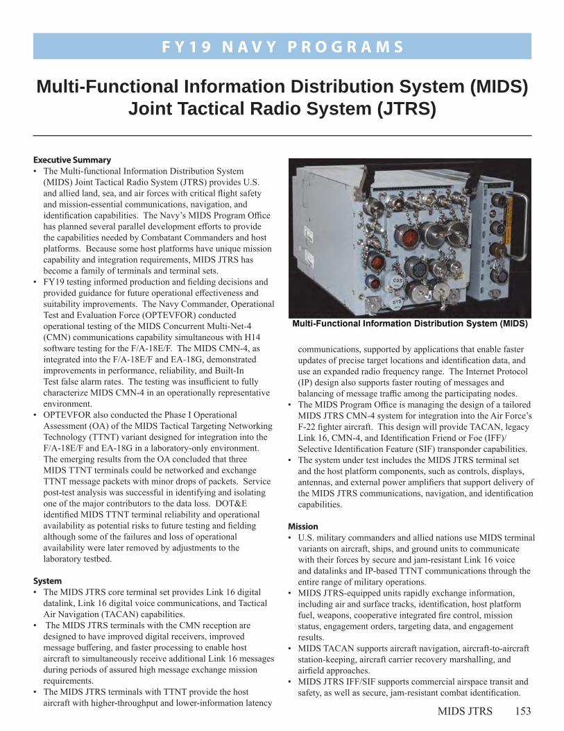
MIDS JTRS 153
communications, supported by applications that enable faster updates of precise target locations and identification data, and use an expanded radio frequency range. The Internet Protocol (IP) design also supports faster routing of messages and balancing of message traffic among the participating nodes.
• The MIDS Program Office is managing the design of a tailored MIDS JTRS CMN-4 system for integration into the Air Force’s F-22 fighter aircraft. This design will provide TACAN, legacy Link 16, CMN-4, and Identification Friend or Foe (IFF)/Selective Identification Feature (SIF) transponder capabilities.
• The system under test includes the MIDS JTRS terminal set and the host platform components, such as controls, displays, antennas, and external power amplifiers that support delivery of the MIDS JTRS communications, navigation, and identification capabilities.
Mission• U.S. military commanders and allied nations use MIDS terminal
variants on aircraft, ships, and ground units to communicate with their forces by secure and jam-resistant Link 16 voice and datalinks and IP-based TTNT communications through the entire range of military operations.
• MIDS JTRS-equipped units rapidly exchange information, including air and surface tracks, identification, host platform fuel, weapons, cooperative integrated fire control, mission status, engagement orders, targeting data, and engagement results.
• MIDS TACAN supports aircraft navigation, aircraft-to-aircraft station-keeping, aircraft carrier recovery marshalling, and airfield approaches.
• MIDS JTRS IFF/SIF supports commercial airspace transit and safety, as well as secure, jam-resistant combat identification.
Executive Summary• The Multi-functional Information Distribution System
(MIDS) Joint Tactical Radio System (JTRS) provides U.S. and allied land, sea, and air forces with critical flight safety and mission-essential communications, navigation, and identification capabilities. The Navy’s MIDS Program Office has planned several parallel development efforts to provide the capabilities needed by Combatant Commanders and host platforms. Because some host platforms have unique mission capability and integration requirements, MIDS JTRS has become a family of terminals and terminal sets.
• FY19 testing informed production and fielding decisions and provided guidance for future operational effectiveness and suitability improvements. The Navy Commander, Operational Test and Evaluation Force (OPTEVFOR) conducted operational testing of the MIDS Concurrent Multi-Net-4 (CMN) communications capability simultaneous with H14 software testing for the F/A-18E/F. The MIDS CMN-4, as integrated into the F/A-18E/F and EA-18G, demonstrated improvements in performance, reliability, and Built-In Test false alarm rates. The testing was insufficient to fully characterize MIDS CMN-4 in an operationally representative environment.
• OPTEVFOR also conducted the Phase I Operational Assessment (OA) of the MIDS Tactical Targeting Networking Technology (TTNT) variant designed for integration into the F/A-18E/F and EA-18G in a laboratory-only environment. The emerging results from the OA concluded that three MIDS TTNT terminals could be networked and exchange TTNT message packets with minor drops of packets. Service post-test analysis was successful in identifying and isolating one of the major contributors to the data loss. DOT&E identified MIDS TTNT terminal reliability and operational availability as potential risks to future testing and fielding although some of the failures and loss of operational availability were later removed by adjustments to the laboratory testbed.
System• The MIDS JTRS core terminal set provides Link 16 digital
datalink, Link 16 digital voice communications, and Tactical Air Navigation (TACAN) capabilities.
• The MIDS JTRS terminals with the CMN reception are designed to have improved digital receivers, improved message buffering, and faster processing to enable host aircraft to simultaneously receive additional Link 16 messages during periods of assured high message exchange mission requirements.
• The MIDS JTRS terminals with TTNT provide the host aircraft with higher-throughput and lower-information latency
Multi-Functional Information Distribution System (MIDS) Joint Tactical Radio System (JTRS)
F Y 1 9 N A V Y P R O G R A M S

154 MIDS JTRS
F Y 1 9 N A V Y P R O G R A M S
Major Contractors• Via Sat, Inc. – Carlsbad, California• Data Link Solutions – Wayne, New Jersey, and
Cedar Rapids, Iowa• Boeing – St. Louis, Missouri
ActivityMIDS JTRS CMN-4• From August through December 2018, the Navy’s Air Test
and Evaluation Squadron Nine conducted an operational test (OT) of the MIDS CMN-4 terminal as integrated into the F/A-18E/F and EA-18G. This test leveraged developmental test (DT) flight sorties, Operational Flight Program H-14 OT flights, deployed live exercise events, as well as dedicated CMN-4 OT flights to gather the needed test data. The Navy conducted testing in accordance with the DOT&E-approved Test and Evaluation Master Plan (TEMP).
• The Program Office is developing the MIDS Block Upgrade 3, which updates the CMN-4 Link 16 transceiver to improve computing processing power, correct previously identified deficiencies, and deliver new capabilities.
MIDS JTRS TTNT• OPTEVFOR conducted the Phase 1 OA of the MIDS
TTNT terminal in the Naval Information Systems Warfare Command’s Waveform Test Laboratory from July 8 – 12, 2019. OPTEVFOR conducted testing in accordance with the DOT&E-approved MIDS TTNT TEMP and OA test plan. The system under test was the MIDS TTNT and TTNT external power amplifier set, designed for integration into the F/A-18E/F and EA-18G aircraft. The results of this test help inform the Navy’s decision to approve low-rate initial production of MIDS TTNT terminal sets to support host platform integration, future OT, and early fielding.
AssessmentMIDS JTRS CMN-4• The F/A-18E/F and EA-18G MIDS CMN-4 OT
demonstrated that many of the operational effectiveness and suitability deficiencies discovered during DT have been corrected. MIDS CMN-4 terminal and integrated system reliability improved to within threshold requirements. Built-In Test false alarms now meet the threshold requirement. Link 16 message completion rates appeared to meet requirements; however, Link 16 data recorders were not available on most test flights, and experienced
high failure rates when they were available. Consequently, testers could not collect meaningful data for analysis in all operational scenarios.
• There were two key OT limitations of the MIDS CMN-4 capability. The Link-16 network was not designed to operationally stress the CMN-4 capability and there were not enough MIDS CMN-4 Link-16 participants available to operationally stress the network. DOT&E will work with the Navy and the Air Force to develop an adequate OT for the MIDS CMN-4 when the appropriate network design is available and the number of CMN-4-configured participants increases.
MIDS JTRS TTNT• MIDS JTRS TTNT Phase 1 OA emerging results indicated
that the three MIDS JTRS terminals participating in this laboratory test could exchange TTNT data packets while simultaneously operating Link 16 on an adjacent communications channel. Emerging results also indicate that message completion rates were within or very close to threshold requirements. A critical limitation to the MIDS JTRS TTNT Phase I OA was the immaturity of the host platform integration efforts.
RecommendationsThe Navy should:
1. Develop an adequate OT plan for the MIDS CMN-4 capability. This test must include a relevant CMN-4 network design and MIDS CMN-4-equipped command and control host platforms.
2. Improve operational availability and reliability of MIDS Link 16 data recorders for testing to accurately record message completion rates, which is a key element of all communications systems testing.
3. Conduct another OA or Integrated Test of MIDS TTNT integrated onto the EA-18G, F/A-18E/F, and E-2D to further define the risks to early operational fielding. Also, conduct a Reliability Growth Test of the MIDS TTNT, which should be completed before entry into OT.
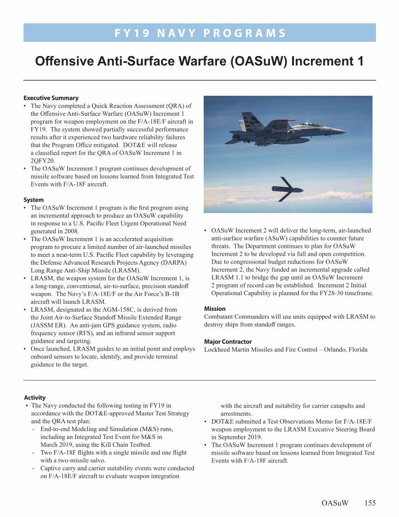
OASuW 155
with the aircraft and suitability for carrier catapults and arrestments.
• DOT&E submitted a Test Observations Memo for F/A-18E/F weapon employment to the LRASM Executive Steering Board in September 2019.
• The OASuW Increment 1 program continues development of missile software based on lessons learned from Integrated Test Events with F/A-18F aircraft.
Activity • The Navy conducted the following testing in FY19 in
accordance with the DOT&E-approved Master Test Strategy and the QRA test plan:- End-to-end Modeling and Simulation (M&S) runs,
including an Integrated Test Event for M&S in March 2019, using the Kill Chain Testbed.
- Two F/A-18F flights with a single missile and one flight with a two-missile salvo.
- Captive carry and carrier suitability events were conducted on F/A-18E/F aircraft to evaluate weapon integration
Executive Summary• The Navy completed a Quick Reaction Assessment (QRA) of
the Offensive Anti-Surface Warfare (OASuW) Increment 1 program for weapon employment on the F/A-18E/F aircraft in FY19. The system showed partially successful performance results after it experienced two hardware reliability failures that the Program Office mitigated. DOT&E will release a classified report for the QRA of OASuW Increment 1 in 2QFY20.
• The OASuW Increment 1 program continues development of missile software based on lessons learned from Integrated Test Events with F/A-18F aircraft.
System• The OASuW Increment 1 program is the first program using
an incremental approach to produce an OASuW capability in response to a U.S. Pacific Fleet Urgent Operational Need generated in 2008.
• The OASuW Increment 1 is an accelerated acquisition program to procure a limited number of air-launched missiles to meet a near-term U.S. Pacific Fleet capability by leveraging the Defense Advanced Research Projects Agency (DARPA) Long Range Anti-Ship Missile (LRASM).
• LRASM, the weapon system for the OASuW Increment 1, is a long-range, conventional, air-to-surface, precision standoff weapon. The Navy’s F/A-18E/F or the Air Force’s B-1B aircraft will launch LRASM.
• LRASM, designated as the AGM-158C, is derived from the Joint Air-to-Surface Standoff Missile Extended Range (JASSM ER). An anti-jam GPS guidance system, radio frequency sensor (RFS), and an infrared sensor support guidance and targeting.
• Once launched, LRASM guides to an initial point and employs onboard sensors to locate, identify, and provide terminal guidance to the target.
Offensive Anti-Surface Warfare (OASuW) Increment 1
F Y 1 9 N A V Y P R O G R A M S
• OASuW Increment 2 will deliver the long-term, air-launched anti-surface warfare (ASuW) capabilities to counter future threats. The Department continues to plan for OASuW Increment 2 to be developed via full and open competition. Due to congressional budget reductions for OASuW Increment 2, the Navy funded an incremental upgrade called LRASM 1.1 to bridge the gap until an OASuW Increment 2 program of record can be established. Increment 2 Initial Operational Capability is planned for the FY28-30 timeframe.
MissionCombatant Commanders will use units equipped with LRASM to destroy ships from standoff ranges.
Major Contractor Lockheed Martin Missiles and Fire Control – Orlando, Florida

156 OASuW
F Y 1 9 N A V Y P R O G R A M S
Assessment • The system experienced two hardware reliability failures
during testing that the program has addressed. The fixes incorporated within the system produced partially successful performance results.
• Accreditation of the M&S environment to fully assess LRASM operational performance is incomplete due to limitations presented by the live Integrated Test Event environment. The M&S environment is required to determine whether the system will meet Key Performance Parameter requirements and demonstrate mission capability in more realistic environments. Further details are classified.
• Flight tests were not conducted in realistic operational environments.
• Data collection and analysis is ongoing and DOT&E will release a classified report for the QRA of OASuW Increment 1 in 2QFY20.
Recommendation1. The Navy should plan and complete cybersecurity testing
and IOT&E for LRASM 1.1 in accordance with FY19 congressional direction.

OTH-WS 157
which examined possible avenues of attack on the system and the resulting mission effects. Because of the Non-Developmental acquisition strategy, the exercise paid special attention to possible supply-side attack methods. The exercise participants, including system operators from LCS Squadron One and cybersecurity penetration testers, based their assessments on system diagrams and subject matter expertise. The Navy plans to conduct cybersecurity testing during IOT&E to validate the findings from the Cyber Table Top assessment.
• The TEMP and LFT&E Strategy are under development. The final scope of the OT/LFT&E programs are contingent upon the adequacy and availability of missile performance data collected by the foreign supplier during the missile’s development.
Activity • The Navy began the OTH-WS program in 2016, and DOT&E
placed the program on oversight in 2016. This is the first time DOT&E has included this program in its annual report.
• The Navy conducted a QRA to support early deployment on the Independence-class LCS. The test, conducted in port at San Diego, California, and underway at the Southern California Operating Area, intended to demonstrate the system’s ability to track a target and plan a missile launch. The QRA consisted of a maintenance/logistic support demonstration, in-port and at-sea system operations, and a cyber-survivability table top assessment.
• The Navy conducted a structural test firing to assess the integration, integrity, and safety of firing the OTH-WS on the Independence-class LCS.
• The Navy conducted a limited assessment of cybersecurity during a Cyber Table Top assessment from July 16 – 19, 2019,
to integrate the OTH-WS on the guided-missile frigate, FFG(X). The OTH-WS will receive targeting data via tactical communications from combatant platforms or airborne sensors and requires no guidance after launch.
Mission• The Joint Force Commander/Strike Group Commander
employs OTH-WS-equipped LCS platforms to conduct offensive over-the-horizon and within-the-horizon engagements against maritime targets.
• The addition of the OTH-WS on board the LCS variants and FFG(X) ships will support the Capstone Concept for Joint Operations Version 3.0.
Major ContractorRaytheon Missile Systems – Tucson, Arizona
Executive Summary• In FY19, the Navy completed a limited Quick Reaction
Assessment (QRA) of the Over-The-Horizon Weapons System (OTH-WS). This event was an assessment of the system’s operational capabilities to support the early installation of the OTH-WS on the Independence-class Littoral Combat Ship (LCS). The QRA did not include a missile launch. The QRA successfully demonstrated the capability to track a target and plan an engagement.
• In FY19, the Navy conducted a structural test firing of the OTH-WS to assess the integrity and safety of the weapon system installation on the launch platform. The test revealed no problems related to the integration of the Missile Launching System with the platform.
• The Navy is planning to conduct IOT&E and LFT&E in FY20-22 and is developing a Test and Evaluation Master Plan (TEMP) and Live Fire Test Strategy to support those test events.
System• The OTH-WS program is a long-range, surface-to-surface
warfare system intended to offensively engage maritime targets both inside and beyond the radar horizon. The system consists of an operator interface console, Naval Strike Missile, and the Missile Launching System.
• The Naval Strike Missile is a bank-to-turn missile with an imaging infrared seeker and employs a semi-armor-piercing warhead optimized for anti-surface warfare.
• The OTH-WS is a stand-alone system requiring minimal integration into the LCS platform. The Navy also intends
Over-the-Horizon Weapon System (OTH-WS)
F Y 1 9 N A V Y P R O G R A M S

158 OTH-WS
F Y 1 9 N A V Y P R O G R A M S
Assessment • Due to the limited scope of the QRA/operational testing, no
assessment of effectiveness or suitability can be made from this test event.
• The QRA demonstrated the OTH-WS’s ability to track a simulated target and to successfully plan tactical engagements. Due to the lack of test missiles to support the accelerated test ship deployment schedule, the program did not plan any live end-to-end flight testing for the QRA.
• Analysis of the cyber survivability table top assessment is ongoing and will be reported in the DOT&E classified OTH-WS Early Fielding Report.
• IOT&E and LFT&E, scheduled for the FY20-22 timeframe, will include live fire tests, modeling and simulation runs, and tailored lethality testing. The Navy is prepared to conduct additional live fire testing to characterize the OTH-WS’s warhead and fuze if the supplier’s previous data are not sufficient.
RecommendationsNone.

SSD DDG 1000 159
performance predictions. The remaining test events are at risk of not occurring for several reasons:- The Navy plans to remove the SPY-3 radar and TSCE
computer equipment on the SDTS at the end of 2QFY20.- Several other test programs are competing for aerial target
resources, time on the SDTS, and allocated time on the range.
Activity • The Navy began this program in FY03, and DOT&E put it on
oversight in FY03. This is the first time DOT&E has included this program in its annual report.
• The Navy conducted 4 of the 10 DDG 1000 tests planned for the SDTS (3 of 6 planned developmental tests, and 1 of 4 planned integrated developmental and operational tests). The Navy canceled one integrated test event and one critical developmental test event because of unacceptably low
• MK 57 Vertical Launch System (VLS) - The DDG 1000-only vertical missile launcher variant.
MissionCommanders use the DDG 1000 self-defense systems (TSCE, SPY-3, CEC, SEWIP Block 2, ESSM and SM-2 with JUWL, and VLS) to protect the ship and its sailors from enemy air threats in both clear and jammed environments.
Major Contractors• TSCE and SPY-3: Raytheon Company, Integrated Defense
Systems – Tewksbury, Massachusetts• ESSM and SM-2 with JUWL, VLS: Raytheon Missile
Systems – Tucson, Arizona• SEWIP Block 2: Lockheed Martin – Syracuse, New York• CEC: Raytheon Company, Integrated Defense Systems – St.
Petersburg, Florida
Executive Summary• The Navy conducted 4 of the 10 DDG 1000 tests planned
for the Self-Defense Test Ship (SDTS) (3 of 6 planned developmental tests, and 1 of 4 planned integrated developmental and operational tests). The Navy canceled one integrated test event and one developmental test event because of unacceptably low performance predictions.
• The Navy discovered severe problems during the DDG 1000 SDTS events that will adversely affect the operational effectiveness of the combat system if not corrected. Consequently, the Navy has put the test program on hold and is currently working to identify the root-cause of these problems.
• The DDG 1000 self-defense test program is at risk of being inadequate if the six remaining SDTS events are not completed.
SystemThe DDG 1000 ship self-defense combat system, Zumwalt Combat System (ZCS), consists of several programs: • Total Ship Computing Environment (TSCE) – The command
and control architecture unique to ZCS. • Multi-Function Radar (MFR/SPY-3) – The new X-band radar
going on DDG 1000-class guided-missile destroyers and the USS Gerald R. Ford (CVN 78).
• Cooperative Engagement Capability (CEC) – The tracker and sensor data fusion and distribution system.
• Surface Electronic Warfare Improvement Program (SEWIP) Block 2 (SLQ-32B(V)6) – The passive electronic sensor used to detect and identify hostile radars.
• Evolved Sea Sparrow Missile (ESSM) Block 1 with Joint Universal Weapon Link (JUWL) – The short-range missile interceptor used to defeat air threats at close-in ranges, and the system used for radar-missile communication and support. Within the U.S. Navy, only the DDG 1000-class ships and the USS Gerald R. Ford (CVN 78) use ESSM with JUWL.
• Standard Missile 2 (SM-2 Block IIIAZ) with JUWL – The unique ZCS variant of SM-2 used to defeat air threats at longer ranges.
Ship Self Defense for DDG 1000
F Y 1 9 N A V Y P R O G R A M S

160 SSD DDG 1000
F Y 1 9 N A V Y P R O G R A M S
- Root cause determination and correcting problems found in developmental and early integrated testing has repeatedly delayed event execution.
• The DDG 1000 Probability of Raid Annihilation (PRA) modeling and simulation testbed has been a critical portion of developmental testing and risk reduction. It is still undergoing development and finalization prior to the operational test runs for the record.
Assessment • The Navy has discovered severe problems during the
DDG 1000 SDTS events that will adversely affect the operational effectiveness of the combat system if not corrected. Consequently, the Navy has put the test program on hold and is currently working to identify the root cause of these problems.
• The DDG 1000 self-defense test program is at risk of being inadequate if the six remaining SDTS events are not completed. These events are required for DOT&E’s evaluation of DDG 1000 self-defense capability, and the Navy cannot
accredit the DDG 1000 PRA testbed without data from these events.
• For use in operational testing, the DDG 1000 PRA testbed requires additional development and improvements, particularly to its missile, radar, and electronic warfare models.
RecommendationsThe Navy should:
1. Provide an execution strategy for completing the DDG 1000 self-defense assessment on the SDTS, to include updated schedule and resource information.
2. Retain test resources not used for the SDTS events for use during the DDG 1000 lead ship air defense scenarios in the event the six remaining SDTS events cannot be executed due to schedule constraints associated with the removal of the SPY-3 radar.
3. Continue to develop and improve the DDG 1000 PRA testbed, in particular its missile, radar, and electronic warfare models.

Virginia 161
shock events. Both test series will improve the confidence in the modeling and simulation (M&S) used to assess Virginia-class Block V survivability. These test series were conducted in accordance with DOT&E-approved test plans and included:- Shallow submergence underwater explosion testing to
validate M&S predictions of the structural response of
Activity • In April 2019, DOT&E approved a Test and Evaluation
Master Plan covering the Block V variant of the Virginia-class submarine. The Navy expects operational test of the Virginia-class Block V submarine in FY27.
• In July 2019, DOT&E submitted a classified FOT&E report on the Virginia-class Block III submarine.
• In FY19, the Navy completed two live fire test series that support a survivability assessment of the vessel to underwater
as providing the potential to host future weapons and unmanned systems. The Navy also intends Block V to include acoustic enhancements and quieting improvements.
MissionThe Operational Commander will employ the Virginia-class Block III submarine to conduct open-ocean and littoral covert operations that support the following submarine mission areas:• Strike warfare• Anti-submarine warfare• Intelligence, surveillance, and reconnaissance• Mine warfare• Anti-surface warfare• Naval special warfare• Battle group operations
Major Contractors• General Dynamics Electric Boat – Groton, Connecticut• Huntington Ingalls Industries, Newport News Shipbuilding –
Newport News, Virginia
Executive Summary• In April 2019, DOT&E approved a Test and Evaluation
Master Plan covering the Block V variant of the Virginia-class submarine. The Navy expects operational test of the Virginia-class Block V submarine in FY27.
• In July 2019, DOT&E submitted a classified FOT&E report on the Virginia-class Block III submarine. The Virginia-class Block III submarine is operationally effective and operationally suitable. The survivability of the Virginia-class Block III submarine is unchanged from Blocks I and II. The Large Aperture Bow (LAB) array is an effective replacement for the legacy spherical array, and the two Virginia Payload Tubes (VPTs) are an effective replacement for 12 legacy vertical launch tubes.
System• The Virginia-class submarine is the Navy’s latest fast-attack
submarine and is capable of targeting, controlling, and launching MK 48 torpedoes and Tomahawk land-attack missiles (TLAMs).
• The Navy is procuring Virginia-class submarines incrementally in a series of blocks; the block strategy is for contracting purposes, not necessarily to support upgrading capabilities. - Block I (hulls 1-4) and Block II (hulls 5-10) ships were
built to the initial design of the Virginia class.- Block III (hulls 11-18) and Block IV (hulls 19-28) ships,
starting with SSN 784, include the following affordability enhancements: ▪ A LAB array in place of the spherical array in the front
of the ship ▪ Two large diameter VPTs replace the 12 vertical launch
tubes; each payload tube is capable of storing and launching 6 TLAMs used in strike warfare missions
- Block V and beyond will increase strike payload capacity from 12 to 40 TLAMs by adding a set of 4 Virginia Payload Modules in an amidships hull extension, capable of storing and launching 7 TLAMs each, as well
SSN 774 Virginia-Class Submarine
F Y 1 9 N A V Y P R O G R A M S

162 Virginia
F Y 1 9 N A V Y P R O G R A M S
representative scaled Tube Stiffened Models (TSM) to underwater shock loading.
- Deep submergence underwater explosion tests to assess structural response of the TSMs to combined shock and pressure loading. This testing utilized explosive charges against TSMs inside a pressure vessel held at deep submergence pressures to build confidence in the ability of M&S tools to predict the onset of structural collapse at operational depths.
Assessment • The DOT&E FOT&E report dated July 31, 2019, concluded
the following regarding performance:- Virginia-class Block III submarine is operationally
effective. ▪ The LAB array is an effective replacement for the
legacy spherical array and supports effective use of Virginia-class Block III submarine for anti-submarine warfare. The Virginia-class Block III submarine capability against diesel submarines remains unknown because submarine acoustic security restricts operational testing against real-world diesel submarines.
▪ Two VPTs are an effective replacement for 12 legacy vertical launch tubes and support the effective use of Virginia-class Block III submarine for strike warfare.
- Virginia-class Block III submarine is operationally suitable with no significant deficiencies identified with operational availability or reliability.
- Cybersecurity results that affect operational effectiveness are in the classified FOT&E report.
- Analysis of the Virginia-class Block III Vulnerability Assessment Report supplement identify that the modifications from Block I to Block III do not degrade the Virginia-class submarine’s ability to support fleet missions or survivability against operationally relevant threat engagements.
Recommendation1. The Navy should address the 15 recommendations in the
classified DOT&E FOT&E report.
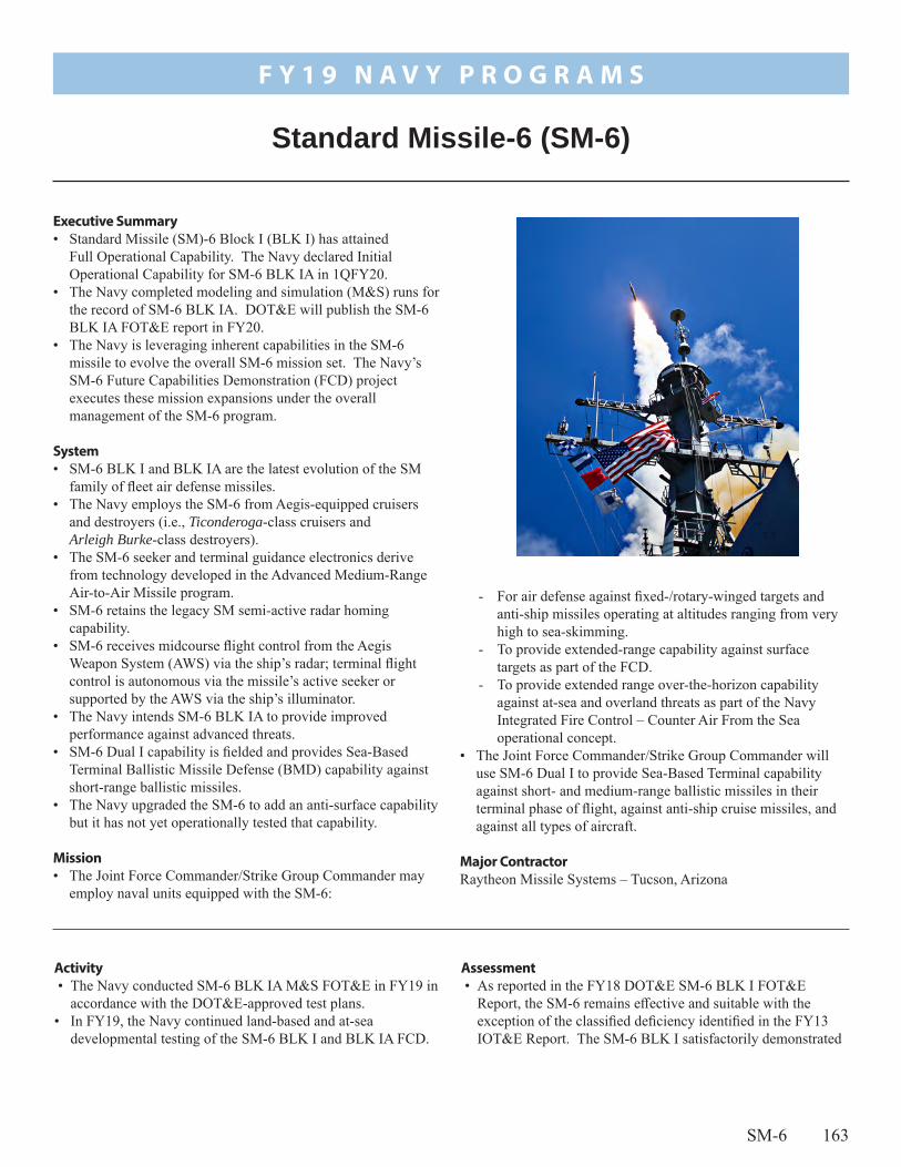
SM-6 163
Assessment • As reported in the FY18 DOT&E SM-6 BLK I FOT&E
Report, the SM-6 remains effective and suitable with the exception of the classified deficiency identified in the FY13 IOT&E Report. The SM-6 BLK I satisfactorily demonstrated
Activity • The Navy conducted SM-6 BLK IA M&S FOT&E in FY19 in
accordance with the DOT&E-approved test plans. • In FY19, the Navy continued land-based and at-sea
developmental testing of the SM-6 BLK I and BLK IA FCD.
- For air defense against fixed-/rotary-winged targets and anti-ship missiles operating at altitudes ranging from very high to sea-skimming.
- To provide extended-range capability against surface targets as part of the FCD.
- To provide extended range over-the-horizon capability against at-sea and overland threats as part of the Navy Integrated Fire Control – Counter Air From the Sea operational concept.
• The Joint Force Commander/Strike Group Commander will use SM-6 Dual I to provide Sea-Based Terminal capability against short- and medium-range ballistic missiles in their terminal phase of flight, against anti-ship cruise missiles, and against all types of aircraft.
Major ContractorRaytheon Missile Systems – Tucson, Arizona
Executive Summary• Standard Missile (SM)-6 Block I (BLK I) has attained
Full Operational Capability. The Navy declared Initial Operational Capability for SM-6 BLK IA in 1QFY20.
• The Navy completed modeling and simulation (M&S) runs for the record of SM-6 BLK IA. DOT&E will publish the SM-6 BLK IA FOT&E report in FY20.
• The Navy is leveraging inherent capabilities in the SM-6 missile to evolve the overall SM-6 mission set. The Navy’s SM-6 Future Capabilities Demonstration (FCD) project executes these mission expansions under the overall management of the SM-6 program.
System• SM-6 BLK I and BLK IA are the latest evolution of the SM
family of fleet air defense missiles. • The Navy employs the SM-6 from Aegis-equipped cruisers
and destroyers (i.e., Ticonderoga-class cruisers and Arleigh Burke-class destroyers).
• The SM-6 seeker and terminal guidance electronics derive from technology developed in the Advanced Medium-Range Air-to-Air Missile program.
• SM-6 retains the legacy SM semi-active radar homing capability.
• SM-6 receives midcourse flight control from the Aegis Weapon System (AWS) via the ship’s radar; terminal flight control is autonomous via the missile’s active seeker or supported by the AWS via the ship’s illuminator.
• The Navy intends SM-6 BLK IA to provide improved performance against advanced threats.
• SM-6 Dual I capability is fielded and provides Sea-Based Terminal Ballistic Missile Defense (BMD) capability against short-range ballistic missiles.
• The Navy upgraded the SM-6 to add an anti-surface capability but it has not yet operationally tested that capability.
Mission• The Joint Force Commander/Strike Group Commander may
employ naval units equipped with the SM-6:
Standard Missile-6 (SM-6)
F Y 1 9 N A V Y P R O G R A M S
164 SM-6
F Y 1 9 N A V Y P R O G R A M S
compatibility with AWS Baseline 9 Integrated Fire Control capability.
• The Navy is not planning operational testing or lethality assessments for SM-6 BLK I and BLK IA FCD. The FCD represent significant warfighting improvements for Aegis destroyers and cruisers. DOT&E, with the Navy’s concurrence, actively participated in the planning and execution of the FY19 and planned future developmental test events, and will report, as appropriate, on these warfighting enhancements.
• Data analysis is underway on the completed SM-6 BLK IA live fire and M&S FOT&E events. DOT&E will report on SM-6 BLK 1A FOT&E in FY20.
RecommendationsThe Navy should:
1. Continue to improve software based on results investigating the classified performance deficiency discovered during IOT&E, perform corrective actions, and verify corrective actions with flight tests. This includes correcting the two new problems identified during FY17 SM-6 BLK I Verification of Corrected Deficiency tests.
2. Plan FOT&E testing and lethality assessments for SM-6 BLK I and BLK IA FCD.

Knifefish UUV 165
- The operational assessment included a total of 12 missions in 2 designated UUV operating areas that contained moored and bottom mine targets accredited by the Navy Operational Test and Evaluation Force as foreign mine surrogates.
- Navy operators trained in Knifefish operations and maintenance completed six missions in each UUV operating area to test Knifefish capability to detect, classify, and identify mines in two different operational environments.
- To assess Knifefish capability to conduct simultaneous UUV missions without mutual interference, missions 6 and 12 launched an additional UUV, which operated in areas
Activity • The Navy began this program in FY10, and DOT&E put it on
oversight in FY10 as a subsystem in the LCS MCM mission package. This is the first time DOT&E has included this program in its annual report.
• DOT&E approved the Milestone B SMCM UUV Knifefish Test and Evaluation Master Plan on August 13, 2012.
• DOT&E approved the SMCM UUV Knifefish Operational Assessment (OT-Bl) Test Plan, Revision 2 on March 29, 2019.
• The Navy completed the operational assessment of Knifefish performance to detect, classify, and identify moored mines, unburied mines, and mines buried in the ocean bottom near the entrance of Boston harbor in May 2019 in accordance with the DOT&E-approved test plan.
or vessels of opportunity, which are ships capable of launching the UUV and supporting Knifefish operations.
MissionThe MCM Commander (MCMC) will employ units equipped with Knifefish to conduct mine reconnaissance operations, such as area or route surveys, in littoral regions throughout the world in support of Combatant Commander operations.
Major Contractor General Dynamics Mission Systems – Quincy, Massachusetts
Executive Summary• The Navy conducted a Surface Mine Countermeasure
(SMCM) Unmanned Undersea Vehicle (UUV) (hereafter referred to a Knifefish) operational assessment to evaluate the system’s capability to detect, classify, and identify naval mines that are moored in the ocean volume and that lay on, or are buried in, the ocean bottom.
• The test results show that Knifefish requires further development to provide an operationally effective and suitable capability for its intended use.
• The Navy plans to incrementally upgrade and test Knifefish capability to meet operational needs prior to IOT&E and fleet introduction.
System• Knifefish is an element of the family of systems needed for
naval mine countermeasure (MCM) capability.• Each Knifefish system includes two UUVs, an operator
console, a planning and post mission analysis (PMA) station, and an Iridium modem with an antenna for communication with the UUV when it is surfaced.
• The UUV is a self-propelled, untethered, unmanned, autonomous undersea vehicle with sensor capability to perform MCM missions in user-designated shallow-water regions.
• The PMA subsystem employs machine-learning algorithms to process sensor data acquired by the UUV after recovery aboard the host platform.
• A Knifefish system will be configured for deployment, operation, and maintenance on a Littoral Combat Ship (LCS)
Surface Mine Countermeasures (SMCM) Unmanned Undersea Vehicle (UUV) (also called Knifefish UUV)
F Y 1 9 N A V Y P R O G R A M S

166 Knifefish UUV
F Y 1 9 N A V Y P R O G R A M S
without mine targets adjacent to the 2 designated UUV operating areas.
• DOT&E completed a classified SMCM UUV Knifefish OT-B1 report in January 2020.
Assessment • The testing was adequate within the scope of the test
objectives; however, the testing occurred in areas and environments similar to those in which the system developers trained and tuned Knifefish’s PMA classification algorithm. Therefore, DOT&E is unable to assess how well the system will perform in operational environments that are new to the system.
• The test targets included a limited number of mine variants that were also used for system development. Testing did not provide data on the system’s capability to detect other mine variants or its capability to distinguish mines from non-mine, mine-like bottom objects, and clutter.
• Due to test limitations, DOT&E is unable to fully assess the system’s ability to detect, classify, and identify buried mines as a function of burial depth.
• While exceeding the operational availability threshold, the system did not meet the Navy’s reliability threshold due to operational mission failures. During two sorties, UUV
hardware failures terminated the sorties. During PMA, hardware and software faults delayed completion of sensor data analysis.
• The operational assessment did not include an evaluation of cybersecurity since the system, software, and interfaces are still in development.
• A complete DOT&E analysis of Knifefish operational assessment test results is available in the classified SMCM UUV Knifefish OT-B1 report.
• Based on the operational assessment, the Navy plans to incrementally upgrade and test Knifefish capability to meet operational needs prior to IOT&E and fleet introduction.
RecommendationsThe Navy should implement the following recommendations to improve operational performance prior to IOT&E and subsequent fleet introduction:
1. Complete system upgrades and conduct additional testing to more fully characterize Knifefish performance in operational environments in which the system capability has not previously been assessed.
2. Specific recommendations are available in the classified SMCM UUV Knifefish OT-B1 report.

VH-92A 167
and have flown 60.5 hours. SDTA-3 is due to deliver in November 2019 and SDTA-4 in May 2020.
• NAVAIR at St. Inigoes, Maryland, is continuing development of the MCS software. Systems integration laboratories,
Activity • EDM-1 and EDM-2 are at NAS Patuxent River supporting
the test program. As of September 30, 2019, the two EDMs have accumulated 328.3 flight hours since delivery to Patuxent River. SDTAs-1 and -2 have been delivered to Patuxent River
• The government-designed MCS will provide the ability to conduct simultaneous short- and long-range secure and non-secure voice and data communications. The MCS will provide situational awareness by exchanging information with outside agencies, organizations, and supporting aircraft. Lockheed Martin in Owego, New York, installs the MCS hardware and baseline software and conducts systems checks as part of VH-92A production.
• Lockheed Martin will conduct final interior finishing and aircraft painting at Owego to complete the VH-92A for delivery.
Mission• Marine HMX-1 will use the VH-92A aircraft to provide safe
and timely transport of the President of the United States and other parties as directed by the White House Military Office.
• HMX-1 will operate the VH-92A from commercial airports, military airfields, Navy ships, and austere sites throughout the world.
Major ContractorSikorsky Aircraft Corporation, a Lockheed Martin Company – Stratford, Connecticut
Executive Summary• The VH-92A program is progressing on
schedule with excellent teamwork and open communication among all agencies involved.
• The Navy has two VH-92A Engineering Development Model (EDM) aircraft and two System Demonstration Test Article (SDTA) aircraft to support government-led integrated testing at Naval Air Station (NAS) Patuxent River, Maryland. This effort includes the integration of the Mission Communications System (MCS) designed by Naval Air Systems Command (NAVAIR) at St. Inigoes, Maryland.
• The Navy conducted an operational assessment (OA) from March 1 through April 9, 2019. Results of the OA supported a Milestone C decision on May 30, 2019.
• Cybersecurity testing on VH-92A included a Cooperative Vulnerability and Penetration Assessment and Adversarial Assessment by the Commander, Operational Test and Evaluation Force Cyber Test Team; and a Cyber Risk Assessment conducted by NAVAIR. Cybersecurity testing of the MCS has been conducted by a U.S. Government Agency.
• The VH-92 program completed the LFT&E program in accordance with DOT&E-approved test plans. DOT&E summarized the preliminary VH-92A survivability assessment in the DOT&E OA report. DOT&E will deliver the final survivability evaluation in FY20 to support Initial Operational Capability.
System• The VH-92A is a dual-piloted, twin-engine helicopter based
on the Sikorsky S-92A. The program will maintain the VH-92A Federal Aviation Administration (FAA) airworthiness certification throughout its lifecycle.
• The VH-92A aircraft will replace the current Marine Corps fleet of VH-3D and VH-60N helicopters flown by Marine Helicopter Squadron One (HMX-1) to perform the presidential airlift mission.
• The VH-92A will operate worldwide in day, night, or adverse weather conditions. The VH-92A will be air transportable to remote locations via a single Air Force C-17 cargo aircraft.
VH-92A Presidential Helicopter Replacement Program
F Y 1 9 N A V Y P R O G R A M S

168 VH-92A
F Y 1 9 N A V Y P R O G R A M S
which replicate the MCS for development, test, and training, are operational and MCS software development is on schedule.
• On September 22, 2018, aircrew from the HMX-1 VH-92A Operational Test Team conducted 14 landings on the White House South Lawn. HMX-1 used observations from these landings to inform the OA in March 2019.
• The Navy completed the first phase of integrated developmental/operational testing for 150 flight hours at Patuxent River.
• During integrated testing, HMX-1 maintainers participated in an air transportability assessment. This assessment used draft procedures and the proposed set of ground support equipment to disassemble, reassemble, and load VH-92A aircraft on a C-17. The transportability assessment involved loading the VH-92A ground support equipment on C-130 and MV-22 aircraft that enable the VH-92A to self-deploy.
• DOT&E participated in an Independent Technical Risk Assessment (ITRA) on February 26 – 28, 2019. The USD(R&E) conducted the ITRA in accordance with statute and policy to support the Milestone C decision. The ITRA team conducted site visits at the Program Office in Patuxent River on February 26, 2019, and the Lockheed Martin Facility in Owego, New York, on February 28, 2019.
• The Commander, Operational Test and Evaluation Force conducted the OT-B1 OA with HMX-1 personnel at NAS Patuxent River from March 1 through April 9, 2019. Testing was conducted in accordance with DOT&E-approved test plans. DOT&E published an OA report in May 2019.- HMX-1 pilots, crew chiefs, and communications system
operators flew 43.1 flight hours over the course of 16 missions. Each mission conducted an operationally representative Administrative Lift or Contingency Operations mission to landing zones used within the National Capital Region, including the White House South Lawn, Camp David, the Naval Observatory, Marine Corps Air Facility Quantico, Joint Base Anacostia-Bolling, Joint Base Andrews, and Naval Air Station Norfolk.
- Representatives from the following White House support agencies participated in flight and ground events during the OA: ▪ United States Secret Service ▪ White House Military Office ▪ White House Communications Agency ▪ White House Medical Unit
• Cybersecurity testing consisted of the following events:VH-92A aircraft
- A Cooperative Vulnerability and Penetration Assessment and Adversarial Assessment of the VH-92A aircraft conducted by the Commander, Operational Test and Evaluation Force Cyber Test Team
- A Cyber Risk Assessment conducted by NAVAIRMission Communications System (MCS)
- Version 3.0 scans conducted by a U.S. Government Agency in a Systems Integration Laboratory
- Version 2.0 testing done by a U.S. Government Agency
- Cyber Risk Assessment conducted by Johns Hopkins University Applied Physics Laboratory
• HMX-1 has taken delivery of all training devices and courseware. HMX-1 expects that courseware and trainer refinements implemented over the next year will provide for a mature system to support IOT&E.
• DOT&E completed a preliminary evaluation of the VH-92A live fire test data.
Assessment • The program is on track to meet program milestones.
Maintenance of FAA airworthiness certification is a key emphasis area.
• The VH-92A provides increased speed, range, and number of passengers compared to in-service aircraft (VH-3D and VH-60N). This increased performance provides greater mission flexibility. Pilots stated that VH-92A autopilot features are a significant improvement over those in the in-service aircraft.
• During the OA, the VH-92A experienced a high number of nuisance faults during the start sequence that delayed its launch. The program is working to resolve these faults.
• The VH-92A meets maintainability metrics for maintenance-hours per flight hour and mean corrective maintenance time. While the aircraft meets threshold values for operational availability, this metric does not capture observed shortcomings associated with MCS inflight availability.
• Reliable communications are needed for Administrative Lift and Contingency Operations missions to support the Office of the President. MCS version 3.1 is currently in development, and will be installed prior to FY20 IOT&E to address these requirements.
• The transportability assessment demonstrated that VH-92A aircraft, support equipment, and personnel fit on C-17, C-130, and MV-22 aircraft as required. While the transportability assessment did not include a formal timed event, HMX-1 marines identified several areas that could improve the loading and unloading process.
• The program is working to meet the Net Ready Key Performance Parameter for the MCS to connect to the Crisis Management System. Security protocol changes enacted after MCS design finalization required development of a near-term solution to support the OA in parallel with a permanent solution to support the IOT&E.
• DOT&E reported on the preliminary VH-92A survivability evaluation in an operationally representative environment in the classified section of the OA report. Final survivability assessment of the VH-92A will include an assessment of available developmental and operational data, as well as modeling and simulation outputs. DOT&E will deliver the final survivability assessment in FY20 to support Initial Operational Capability.
F Y 1 9 N A V Y P R O G R A M S
VH-92A 169
RecommendationsThe Navy should address the following recommendations from the May 2019 DOT&E OA report:
1. Perform MCS Version 3.0 integrated testing using the OA communications scripts to aid in early identification of deficiencies.
2. Develop MCS connectivity metrics and rationale to allow for determining the operational effects of system shortcomings that might arise during IOT&E.
3. Collect in-service aircraft Administrative Lift and Contingency Operations mission data to allow for a comparative assessment between VH-92A and in-service aircraft during IOT&E.
4. Review the definition and threshold value for the Mean Time Between Operational Mission Failures to account for differences in Administrative Lift and Contingency Operations missions.

170
F Y 1 9 N A V Y P R O G R A M S

Air Force Programs

Air F
orce
Pro
gram
s

F Y 1 9 A I R F O R C E P R O G R A M S
AMRAAM 171
Cybersecurity• The Air Force and Navy began combined cybersecurity
testing of the AMRAAM missile in June 2018 and will complete in 2QFY20.
Assessment• AMRAAM continues to be operationally effective and
suitable.• The AIM-120D SIP-1 missile meets performance and
reliability requirements.
Activity• The Air Force and Navy conducted all testing in accordance
with DOT&E-approved test plans.AIM-120D SIP• The Air Force and Navy are conducting SIP-2 operational
testing, which is scheduled to complete in 1QFY20 with fielding in 2QFY20.
AIM-120C7 AEPIP• The Air Force and Navy have completed operational
testing for the AEPIP software upgrade to C7 missiles. Testing began in FY16 and completed in 1QFY19. AEPIP Tape 2 fielded in 2QFY19.
and software improvements over the AIM-120C3-C7. Four planned follow-on SIPs will provide updates to the AIM-120D to enhance missile performance and resolve previous deficiencies.
Mission• The Air Force and Navy, as well as several foreign military
forces, employ various versions of the AIM-120 AMRAAM to conduct air-to-air combat missions.
• All U.S. fighter aircraft use the AMRAAM as the primary beyond-visual-range air-to-air weapon.
Major ContractorRaytheon Missile Systems – Tucson, Arizona
Executive Summary• The Advanced Medium-Range Air-to-Air Missile
(AMRAAM), including Air Intercept Missile (AIM)-120D, System Improvement Program (SIP)-1, and AIM-120C3-7, continues to be operationally effective and suitable.
• The Air Force and Navy completed operational test activities for the AIM-120D SIP-1 in November 2016 and fielded SIP-1 in April 2017. SIP-2 OT&E began in September 2018.
• The Air Force and Navy began operational test activities for the AIM-120C7 AMRAAM Advanced Electronic Protection Improvement Program (AEPIP) in 2016, with testing continuing through 2018. AEPIP Tape 1 testing completed in August 2017 and fielded in March 2018. AEPIP Tape 2 testing completed in October 2018 and fielded in February 2019.
• The Air Force and Navy began combined missile cybersecurity testing of AMRAAM in June 2018.
System• AMRAAM is a radar-guided, air-to-air missile with capability
in both the beyond-visual-range and within-visual-range arenas. A single aircraft can engage multiple targets with multiple missiles simultaneously when using AMRAAM.
• F-15C/D/E, F-16C/D, F/A-18C/D/E/F, EA-18G, F-22A, F-35A/B/C, and AV-8B aircraft are capable of employing AMRAAM.
• The AMRAAM program develops and incorporates planned, periodic software upgrades. The AMRAAM AEPIP is a software upgrade to AIM-120C7. The AEPIP upgrade delivered new capability in two installments, Tape 1 and Tape 2.
• The AIM-120D is the next variant in the AMRAAM family of missiles. The newest missile includes both hardware
AIM-120 Advanced Medium-Range Air-to-Air Missile (AMRAAM)

F Y 1 9 A I R F O R C E P R O G R A M S
172 AMRAAM
• The AIM-120C3-7 missiles meet performance and reliability requirements.
RecommendationsNone.

F Y 1 9 A I R F O R C E P R O G R A M S
AOC-WS 173
The networks connect the core operating system and primary applications to joint and coalition partners.
• AOC-WS 10.2 was a program designed to upgrade legacy 10.1 capabilities with a modernized, integrated, and automated approach to AOC operations.
• USD(AT&L) canceled the AOC-WS 10.2 program in 2018. The AOC-WS 10.2 requirements remain valid.
• A subset of the AOC-WS 10.2 program was the C2AOS-C2IS program. C2AOS-C2IS was a software developmental program to upgrade critical AOC-WS mission software, including TBMCS.
• PEO Digital intends to deliver these capabilities via the MTA AOC Modifications “Block 20” program. The Air Force’s organic KREL software development organization focuses on this effort.
MissionThe Commander, Air Force Forces or the Joint/Combined Forces Air Component Commander uses the AOC-WS to exercise C2 of joint (or combined) air forces, including planning, directing, and assessing air, space, and cyberspace operations; air defense; airspace control; and coordination of space and mission support not resident within theater.
Major Contractors• AOC-WS 10.1 Production Center: Raytheon Intelligence,
Information and Services – Dulles, Virginia• AOC-WS Modifications “Block 20” (Section 804): Air
Force KREL – Boston, Massachusetts; Pivotal Software, Inc – Washington, D.C.
Executive Summary• The USD(AT&L) canceled the Air Operations Center –
Weapon System (AOC-WS) 10.2 program in 2018.• Part of the AOC-WS 10.2 program was the Command and
Control (C2) Air Operations Suite – C2 Information Services (C2AOS-C2IS).
• In July 2018, the Air Force Program Executive Officer (PEO) Digital transitioned C2AOS-C2IS to a middle tier of acquisition (MTA) rapid prototyping effort under the AOC-WS Modifications “Block 20” program.
• In March 2019, PEO Digital concluded the C2AOS-C2IS program MTA rapid prototyping effort.
• AOC-WS “Block 20” capabilities are being developed by the Kessel Run Experimentation Lab (KREL); an organic Air Force software development MTA effort.
System• The AOC-WS (AN/USQ-163 Falconer) is a system of systems
that incorporates numerous third-party software applications and commercial off-the-shelf products. Each third-party system integrated into the AOC-WS provides its own programmatic documentation.
• AOC-WS capabilities include C2 of joint theater air and missile defense; pre-planned, dynamic, and time-sensitive multi-domain target engagement operations; and intelligence, surveillance, and reconnaissance operations management.
• The AOC-WS consists of:- Commercial off-the-shelf software and hardware for voice,
digital, and data communications infrastructure.- Government software applications developed specifically
for the AOC-WS to enable planning, monitoring, and directing the execution of air, space, and cyber operations to include: ▪ Theater Battle Management Core Systems
(TBMCS) – Force Level ▪ Master Air Attack Plan Toolkit (MAAPTK)
- Other government software applications used by the AOC-WS to enable joint and interagency integration include: ▪ Global Command and Control System – Joint (GCCS-J) ▪ Joint Automated Deep Operations Coordination System
- Additional third-party systems that accept, process, correlate, and fuse C2 data from multiple sources and share them through multiple communications systems.
• When required, the AOC-WS operates on several different networks, including the SIPRNET, Joint Worldwide Intelligence Communications System, and coalition networks.
Air Operations Center – Weapon System (AOC-WS)

F Y 1 9 A I R F O R C E P R O G R A M S
174 AOC-WS
Activity• In November 2018, the 605th Test and Evaluation Squadron
(TES) completed the Adversarial Assessment (AA) of AOC-WS 10.1 Release 10.1.15 in accordance with the DOT&E-approved test plan. DOT&E published the classified AOC-WS 10.1 Release 10.1.15 final report in May 2019.- Release 10.1.15 updates software applications including
GCCS-J, MAAPTK, and TBMCS – Force Level.- Additionally, Release 10.1.15 updates hardware and
software providing core services, to include privileged SIPRNET tokens, virtualized servers, and updated server and workstation operating systems.
- No cybersecurity assessments have been conducted on the “Block 20” Modification program.
• After the deployment of AOC-WS 10.1 Release 10.1.15, the AOC-WS 10.1 program transitioned to an Agile Release Event (ARE) construct. In October 2018, 605 TES started development of a Continuous Risk Assessment (CRA) process to support the ARE process. DOT&E was able to monitor and approve the CRA for the first time in October 2019. Five AREs have been released since the transition.
• PEO Digital transitioned the C2AOS-C2IS requirements to an MTA rapid prototyping program in July 2018. Then, in March 2019, PEO Digital concluded the MTA rapid prototyping program.
• The AOC-WS 10.2 requirements, including the former C2AOS-C2IS capabilities, such as TBMCS and MAAPTK, are now dispersed among five portfolios in the Kessel Run MTA Air Operations Branch: Allocations, Taskings, and Re-tasking; Data Science; Intelligence Collection; Objectives, Monitoring, and Assessments; and Target Development.
• The 47th Cyberspace Test Squadron completed an initial discovery and limited assessment of the KREL in June 2019,
and published a classified report of the cybersecurity vulnerabilities in July 2019.
• The Air Force has not updated the 2011 Test and Evaluation Master Plan (TEMP) or applicable test plans to reflect the new processes.
Assessment• The Air Force adequately tested Release 10.1.15 during
integrated developmental and operational test.• Release 10.1.15 demonstrated the required capabilities for
the AOC to execute the joint air tasking order cycle and conduct operational C2 of theater air operations. AOC-WS is operationally effective.
• The AA for AOC-WS Release 10.1.15 identified new Category I deficiencies that degrade the survivability of the AOC. DOT&E published a classified Final Report in May 2019.
• The Air Force has not developed a plan to collect and report reliability, availability, and maintainability data.
RecommendationsThe Air Force should:
1. Fix or mitigate the Category I cybersecurity and functional deficiencies in AOC-WS 10.1 Release 10.1.15.
2. Submit a TEMP and applicable test plans for DOT&E approval that reflects the MTA rapid fielding process.
3. Implement a solution to meet the long-standing requirement to collect and report reliability, availability, and maintainability data for the AOC-WS.

F Y 1 9 A I R F O R C E P R O G R A M S
B-52 CERP 175
program. Primary engine competitors include General Electric, Rolls Royce, and Pratt & Whitney with final selection planned in January 2021. Competing contractors are expected to deliver initial aerodynamic models in early FY20.
• The Air Force is pursuing a three-part rapid prototyping strategy beginning with development of a Virtual Power Pod Prototype (vPPP) digital model for each candidate engine to assess two engine, side-by-side pod design options. Results from the vPPP models will support development of a Virtual System Prototype (vSP) full aircraft digital model of the
Activity• The Air Force began the B-52H CERP program in early
2018, and DOT&E placed the program on oversight in February 2018. This is the first time DOT&E has included this program in its annual report.
• The Air Force formally designated B-52H CERP as a rapid prototyping MTA program in September 2018 leading to acquisition of approximately 650 engines to modify and support the 76-aircraft B-52H fleet. The Air Force implemented a government-led engine source selection strategy coupled with a prime contractor-led integration
MissionTheater Commanders use units equipped with the B-52H to conduct long-range, all-weather conventional and nuclear strike operations that employ a wide range of munitions against ground and maritime targets in low-to-medium adversary threat environments. B-52 theater mission tasks include strategic attack, time-sensitive targeting, air interdiction, close air support, suppression/destruction of enemy air defenses, maritime mining, and nuclear deterrence. Key B-52H mission capabilities include:• Large and versatile internal and external weapons payload• All-weather targeting sensors and systems• Unrefueled intercontinental range extended by air refueling
capability• Rapid nuclear alert start and launch capabilities• Nuclear-hardened and certified avionics and communication
systems
Major Contractor Boeing Defense, Space, and Security – St. Louis, Missouri
Executive Summary• The Air Force is conducting government-led engine source
selection process with final engine selection planned for January 2021. Primary engine competitors include General Electric, Rolls Royce, and Pratt & Whitney. Competing contractors are expected to deliver initial aerodynamic models in early FY20.
• The B-52 Commercial Engine Replacement Program (CERP) Test and Evaluation Master Plan (TEMP) is in final Service coordination. Final DOT&E approval is anticipated in January 2020 to fulfill National Defense Authorization Act (NDAA) 2020 requirements.
• The B-52 CERP middle tier of acquisition (MTA) rapid prototyping development program is built around a five-phase integrated test strategy designed to maximize operational test data collection during the prototyping phase. It includes a limited operational demonstration using prototype aircraft followed by a comprehensive IOT&E using Low-Rate Initial Production (LRIP) aircraft prior to a Full-Rate Production decision.
System• The B-52H is a long-range, all-weather bomber with a crew
of two pilots, two weapon system officers, and an electronic warfare officer.
• Mission systems include a GPS-aided precision navigation system, strategic radar targeting systems, electronic combat systems, and worldwide communications and data transfer systems.
• The B-52H can carry up to 80,000 pounds of precision-guided or unguided conventional and nuclear stores in an internal bomb bay and/or external wing pylons.
• The B-52H CERP replaces the legacy TF33 engines with fuel-efficient, commercial-derivative engines, increases electrical power generation capacity, and integrates digital engine controls and displays.
B-52 Commercial Engine Replacement Program (CERP)

F Y 1 9 A I R F O R C E P R O G R A M S
176 B-52 CERP
selected engine to support a preliminary system design assessment. System-level vSP assessments will be followed by physical modification of two B-52H prototype aircraft to support initial aircraft performance, flying quality, and structural test activities.
• The Air Force developed a fleet modification/production strategy for the remaining 74 B-52H aircraft. This strategy includes production of 11 LRIP aircraft to support the final phase of system development testing and IOT&E. The remaining 65 aircraft would be produced in 6 full-rate production lots. The Air Force continues to evaluate options to accelerate production and fielding, including the potential use of the MTA rapid fielding pathway.
• The Air Force initiated development of a B-52 CERP Capabilities Development Document (CDD) to comply with NDAA 2020 direction to establish formal operational requirements for this program.
• The Air Force developed a B-52 CERP TEMP and began Service coordination August 2020. The program established a B-52 CERP Integrated Test Team to initiate and manage the integrated test planning, execution, and data collection activities outlined in the TEMP.
• The B-52H Program Office initiated development of a comprehensive, enterprise-level cybersecurity test strategy that will progressively conduct incremental cybersecurity assessments across multiple B-52 modernization programs, including B-52 CERP. This approach is intended to maximize cyber test efficiency while supporting cyber test requirements for multiple B-52 upgrade programs.
Assessment • The Air Force is progressing toward fulfillment of the NDAA
2020 requirement to submit a B-52 CERP TEMP for DOT&E approval. The TEMP is in final Service coordination with submission for DOT&E approval anticipated in January 2020. This document defines a five-phase integrated test strategy designed to maximize collection of operationally relevant test data during the prototyping phase and a limited operational demonstration of the two prototype aircraft. The TEMP
also defines the test requirements and resources necessary to complete an adequate IOT&E using production-representative LRIP aircraft prior to a Full-Rate Production/fleet modification decision. The TEMP will be updated, if required, following approval of the B-52 CERP CDD that will finalize program operational requirements.
• The Air Force Operational Test and Evaluation Center (AFOTEC) operational test strategy provides an adaptive framework to support progressive evaluation of system capabilities during prototype development. The AFOTEC operational test design, early data collection strategy, and cumulative reporting approach provides an adequate basis for tailored integration of operational testing with the B-52 rapid prototyping program. Prototype testing will culminate in an AFOTEC operational demonstration to assess residual conventional and nuclear mission capabilities.
• The program test strategy also includes a B-52 CERP IOT&E, using LRIP aircraft, following program transition from prototyping to a more traditional final development and production program. IOT&E will leverage all previously collected test data to support a final evaluation of production system operational effectiveness, suitability, and survivability across the full spectrum of nuclear, conventional, and training missions.
RecommendationsThe Air Force should:
1. Continue to develop B-52 CERP detailed test plans to integrate developmental and operational test objectives during the rapid prototyping test phases.
2. Complete development of a comprehensive, enterprise-level B-52H cybersecurity strategy to establish a system cybersecurity baseline and progressively evaluate planned system upgrades while leveraging previous test results to reduce redundant testing. This strategy should encompass B-52 CERP and other B-52 modernization programs.

F Y 1 9 A I R F O R C E P R O G R A M S
B61 177
• The Air Force conducted an Operational Test Readiness Review on February 13, 2019, intending to start flight testing in April and complete testing in September. Ongoing NNSA production delays impeded the delivery of test articles and resulted in postponing the start of flight testing until September 2019.
Activity• After delivery of OT weapons, the Air Force initiated
the OT phase in August 2019, and began flight testing on September 10, 2019. OT flight testing to date includes: B-2 seven munitions and F-15E eight munitions.
• Reliability testing included the 22 DT releases, 13 additional DOE/NNSA system qualification flight tests, and 15 OT releases with no reliability failures to date.
• The TKA design does not include a GPS receiver. It receives pre-programmed target location data and updates from the aircraft prior to release.
• The Air Force is testing the TKA in accordance with DOD Instruction 5000.02 requirements. The NNSA leads B61-12 BA activities, and the BA will be tested and qualified per the NWC Phase 6.X Process. When mated, the BA and TKA constitute an AUR, which will be qualified in accordance with the B61-12 System Qualification Plan.
MissionA unit equipped with the air-delivered B61-12 nuclear weapon plays a critical role in supporting the airborne leg of the nuclear triad for the United States and allies. The B61 thermonuclear bomb family is a key component of the current U.S. nuclear deterrence posture.
Major ContractorBoeing Defense, Space & Security – St. Louis, Missouri
Executive Summary• The B61 Mod 12 (B61-12) Life Extension Program (LEP)
Tail Kit Assembly (TKA) program began operational flight testing in September 2019, and continued Department of Energy (DOE) system qualification testing. Ongoing operational flight testing thus far included seven weapons dropped from B-2s and eight weapons dropped from F-15Es.
• When hardware is available, side-by-side comparison testing of the respun Bomb Assembly (BA) Weapon Control Unit (WCU), with replacement capacitors, will be required for DOT&E to determine if the weapons deployed during operational testing (OT) completed to date are production representative and are valid for IOT&E. The capacitors in the original design did not meet long-life reliability requirements.
• The TKA demonstrated high degrees of accuracy and reliability throughout developmental testing (DT) and in OT to date with no reliability failures. The Air Force Operational Test and Evaluation Center (AFOTEC) analysis of OT flight tests conducted in September and October 2019 is expected to be available in December 2019.
System• The Nuclear Weapons Council (NWC) directed the
B61-12 LEP as part of the Nuclear Modernization effort. The B61-12 LEP extends the life of the gravity-released ballistic bomb while adding a guidance capability.
• The B61-12 LEP consolidates four legacy B61 variants (Mods 3, 4, 7, and 10) into a single variant.
• The B61-12 All-Up-Round (AUR) is comprised of an updated BA integrated with a new TKA. The DOE National Nuclear Security Administration (NNSA) supplies the BA and the U.S. Air Force supplies the TKA. The NNSA is updating the BA to address all age-related deficiencies.
• The TKA is mechanically mated and electrically connected to the nuclear BA. The TKA and BA communicate with each other and with the aircraft to provide the AUR guide-to-target capability (System 2), while retaining the legacy ballistic flight capability (System 1).
B61 Mod 12 Life Extension Program Tail Kit Assembly

F Y 1 9 A I R F O R C E P R O G R A M S
178 B61
• In FY18, Sandia National Lab conducted comparison testing between two different versions of the WCU to determine if there were any performance differences between BAs equipped with WCUs containing Field Programmable Gate Array (FPGA) chips and those containing Application-Specific Integrated Circuit chips. DOT&E required this comparison testing to determine if FPGA-equipped BAs were production representative for use in IOT&E.
• In FY19, the NNSA identified new problems with the long-life reliability of commercial off-the-shelf capacitors used in non-nuclear components, including the WCU, of the BA. Production-representative WCUs, with the new capacitors, will not be available until early CY21.
• AFOTEC Detachment 2, with support from Sandia National Lab, conducted a Cooperative Vulnerability and Penetration Assessment and an Adversarial Assessment in May and June 2018, respectively, to assess the cyber resilience of the B61-12 LEP TKA.
Assessment• Air Force DT of B61-12 LEP TKA is complete and OT is
ongoing. DOE/NNSA system qualification testing is also ongoing. Preliminary results to date indicate:- The TKA demonstrates high reliability, availability, and
accuracy. There have been no reliability failures during
flight test, and AFOTEC analysis of OT flight tests conducted in September and October 2019 is expected to be available in December 2019.
- One system component presents a cybersecurity vulnerability, but mitigation or elimination of the vulnerability appears feasible without a major investment of time or money.
• WCU comparison test data allowed DOT&E to determine that current flight test articles with FPGA chips in the WCU are production representative for the purpose of IOT&E.
• Additional comparison testing using respun WCUs with replacement capacitors, will be required to allow DOT&E to determine if the WCUs in the flight test articles are production representative for the purpose of IOT&E.
Recommendations1. The Air Force should resolve the outstanding cybersecurity
problems discovered during cybersecurity testing.2. The DOD should identify requirements of side-by-side
comparison testing between WCUs used in IOT&E flight test articles and new WCUs with production capacitors to verify the articles used in IOT&E were production representative. Observation of adequate DOE/NNSA comparison testing is an exit condition of IOT&E.

F Y 1 9 A I R F O R C E P R O G R A M S
C-130J 179
inadequate technical tools and the lack of access to proprietary system software.
• AFOTEC published an IOT&E report in June 2019 and a classified cybersecurity annex in August 2019.
• The Air Force approved the Full-Rate Production decision on the BU8.1 retrofit in October 2019.
Activity• AFOTEC conducted a cybersecurity AA of the C-130J BU8.1
as the final IOT&E test event at Little Rock AFB, Arkansas, in March 2019. The 57th Information Aggressor Squadron portrayed the cyber threat.
• AFOTEC conducted the cybersecurity AA test in accordance with the DOT&E-approved AA plan, but some deviations from the plan were necessary during execution due to
- Air-land delivery of passengers, troops, and cargo- Emergency aeromedical evacuations
• Combat Delivery units operate globally in civil-controlled airspace and in all weather and lighting conditions.
Major ContractorLockheed Martin Aeronautics Corporation – Fort Worth, Texas
Executive Summary• The Air Force Operational Test and Evaluation Center
(AFOTEC) completed IOT&E in March 2019 and published an IOT&E report in June 2019. DOT&E analysis of IOT&E data is ongoing.
• IOT&E data indicate that although the Block Upgrade 8.1 (BU8.1) modification provides the communications and navigation required to meet international airspace regulations, to continue performing the combat delivery mission, numerous shortfalls in usability, training, and technical data hinder the efficacy of the upgrade. The Air Force is planning subsequent software updates to address these shortfalls.
• AFOTEC conducted a cybersecurity Adversarial Assessment (AA) of a BU8.1 aircraft in March 2019 with some limitations caused by inadequate technical tools and lack of access to proprietary system software. Findings will be published in a DOT&E classified report in 2QFY20.
System• The C-130J is a medium-sized, four-engine, turboprop, and
tactical transport aircraft.• The C-130J digital avionics and navigation systems enabled
the Air Force to reduce the flight deck aircrew to two pilots, eliminating the navigator and flight engineer positions. Since fielding the C-130J, the Air Force has been implementing periodic Block Upgrades to improve workload and human factors for the reduced aircrew.
• BU8.1 provides navigation and communication updates to the C-130J to comply with International Civil Aviation Organization requirements and ensure continued access to civil airspace. It will field a Link 16 capability and deficiency corrections that were provided by the Block Upgrade 7.0, which the Air Force did not field after developmental testing.
Mission• Combatant Commanders use the C-130J within a theater of
operations for Combat Delivery missions that include:- Airdrop of paratroopers and cargo (palletized,
containerized, bulk, and heavy equipment)
C-130J

F Y 1 9 A I R F O R C E P R O G R A M S
180 C-130J
• AFOTEC conducted testing consistent with the C-130J Block 8.1 Test and Evaluation Master Plan, approved by DOT&E on March 15, 2018.
Assessment• DOT&E analysis of IOT&E data was ongoing at the beginning
of FY20. • The C-130J BU8.1 remains capable of performing the
air-land and airdrop combat delivery missions with improved navigation capabilities, but key components of the BU8.1 upgrade increased aircrew workload or fell short of operational requirements.
• Overall system reliability enabled maintenance personnel to support the necessary sortie generation rate during IOT&E in spite of shortfalls in integrated diagnostics, technical data, and training.
• Key BU8.1 communication and navigation upgrades enable C-130J compliance with Global Air Traffic Management requirements and continued access to worldwide airspace. Those subsystems include Automatic Dependent Surveillance-Broadcast Out; civil datalinks; and Required Area Navigation (RNAV)-compliant dual flight management system.
• Failures of the Communication/Navigation/Identification – System Processors (CNI-SP), observed on 11 of 52 missions, increased aircrew workload and led to 5 mission failures. Persistent failure of CNI-SP will jeopardize access to portions of RNAV-regulated airspace.
• The Link 16 upgrade does not support enhanced C-130J interoperability. A draft C-130J Link 16 concept of operations (CONOPS) was utilized during Block 8.1 IOT&E. The lack of implementation of a Link 16 CONOPS in Air Mobility Command (AMC) hinders successful connection to tactical networks. AMC is in the process of developing a Mobility Air Forces Link 16 CONOPS. Hardware and software
usability shortfalls hinder aircrew operation of the system. The Program Office is working with the Air Force System Interoperability Test organization and the Joint Interoperability Test Command (JITC) towards interoperability certification.
• Shortfalls in controls and displays, civil datalinks, and voice communications contributed to increased aircrew workload, decreased system usability, or decreased aircrew situational awareness.
• The cybersecurity AA was limited by lack of access to contractor proprietary information and incomplete technical tools on the part of the cyber-threat operators team (such as datalink test tools). The AA was sufficient to demonstrate mission-limiting shortfalls. Further results will be published in a classified report.
• BU8.1 is the last block upgrade for C-130J; the Air Force intends to continue deficiency corrections and capability enhancements through primarily software-based capability management upgrades (CMU). CMU 1 was already in development prior to BU8.1 IOT&E and is unlikely to address any deficiencies identified in that test. Deficiency reports issued by AFOTEC and an interim status report of the IOT&E informed planning for CMU 1C, which is intended to fix the most critical problems, notably the CNI-SP failures. The Air Force intends to field CMU 1C in FY21. Other problem areas will be addressed in CMU 2 planned for fielding in FY24.
RecommendationsThe Air Force should:
1. Address CNI-SP failures and other Deficiency Reports, and verify corrections in follow-on testing.
2. Fully implement the Link 16 CONOPS and demonstrate interoperability in follow-on testing with JITC.
3. Develop or identify advanced cybersecurity test tools and conduct cybersecurity testing during FOT&E in areas that the IOT&E AA did not address.

F Y 1 9 A I R F O R C E P R O G R A M S
CRH 181
fuel cell to evaluate the fuel cell vulnerability to expected small arm and high explosive incendiary threats.
• In November 2018, the Program Office completed the live fire testing of the legacy aerial refueling system to determine the likelihood of initiation of an onboard fire. In April 2019, the Program Office performed fire sustainment testing in aircraft-representative dry bays to evaluate the time to flight-critical failures.
• In July 2019, after completing a set of qualification testing for the cabin and cockpit armor, the Program Office started the live fire testing of armor coupons to evaluate the effectiveness of the armor against expected threats.
• The program has conducted LFT&E in accordance with the DOT&E-approved Alternate LFT&E Strategy.
Activity• The Air Force began integrated contractor-government
developmental test (DT) with four EMD aircraft and one System Demonstration Test Article aircraft at West Palm Beach, Florida, and Stratford, Connecticut.
• The 47th Cyber Test Squadron and the Program Office conducted three phases of Cyber Vulnerability Investigation in the CRH Systems Integration Laboratory.
• The Air Force held a Milestone C decision review in September 2019 to begin low-rate initial production.
• The CRH Program Office prepared a Test and Evaluation Master Plan (TEMP) update to support Milestone C, but the Air Force has not yet submitted it to DOT&E for approval.
• In November 2018, the Program Office completed the qualification testing and limited live fire testing of a full-size
Mission• Commanders will employ units equipped with the HH-60W
to: - Recover isolated personnel from hostile or denied territory,
day or night, in adverse weather, and in a variety of threat environments from terrorist attacks to chemical, biological, radiological, and nuclear threats.
- Conduct humanitarian missions, civil search and rescue, disaster relief, medical evacuation, and non-combatant evacuation operations.
Major ContractorSikorsky Aircraft Corporation – Stratford, Connecticut
Executive Summary• The HH-60W Combat Rescue Helicopter (CRH) is currently
in the Engineering and Manufacturing Development (EMD) phase, with first flight of an EMD aircraft completed in May 2019.
• Qualification testing of many components of the aircraft has uncovered technical deficiencies. As a result, the program began flight test with a large number of CRH-specific systems in non-operationally representative configurations.
• The Air Force held a Milestone C decision review on September 24, 2019.
System• The HH-60W CRH is a new-build, dual-piloted, multi-engine
rotary-wing aircraft based on the UH-60M.• The aircraft is designed to fly a combat radius of at least
195 nautical miles without aerial refueling and conduct an out-of-ground effect hover at its mid-mission gross weight.
• The HH-60W survivability enhancement features are intended to be equivalent to or better than the current HH-60G aircraft:- Crew and cabin armor, self-sealing fuel cells that do not
suffer catastrophic damage from high-explosive incendiary rounds, and crew and passenger crashworthy seating
- Two external mount gun systems with forward and side-firing crew-served weapons including the GAU 2B, GAU-18, and GAU-21
- Aircraft survivability equipment including the AN/ AAR-57(V)3 common missile warning system, the AN/ALE-47 countermeasures dispenser set, the AN/AVR-2B(V)1 laser detecting system, and the AN/ APR-52(V)1 radar warning receiver (RWR)
- An upturned exhaust system to reduce its infrared (IR) signature
Combat Rescue Helicopter (CRH)
F Y 1 9 A I R F O R C E P R O G R A M S
182 CRH
Assessment• DT generated satisfactory performance data to support the
Milestone C decision. The HH-60W demonstrated the ability to meet hover, range, airspeed, payload, and fuel consumption requirements. There is little margin in maximum gross weight to accommodate any weight growth caused by design or equipment changes. Furthermore, the DT has been on non-operationally representative aircraft, with planned updates to include aircraft software, aircrew seating, and armor.
• The Air Force Operational Test and Evaluation Center identified several deficiencies:- Poorly designed hover symbology does not provide
necessary safety-of-flight cues in degraded visual environments.
- The mission planning system will not be available in an operationally representative configuration at the start of IOT&E. Although aircrews will be able to generate mission data through workarounds or alternative tools, the extent of modifications to both the mission planning system and aircraft system software may limit the evaluation. The Program Office is working to provide more complete mission planning capabilities during IOT&E.
• Reliability and availability during early developmental testing have supported the required sortie generation rate. However, preliminary reliability data are not consistent with the reliability growth strategy in the approved TEMP. The Program Office has evaluated the Milestone C data against a contractual specification to meet the reliability requirement roughly 2 years after IOT&E, but the projected reliability during IOT&E may not meet the requirement.
• The developmental AN/APR-52(V)1 RWR performed comparably to similar fielded systems in subsystem-level Integrated Demonstrations and Applications Laboratory testing. On-aircraft developmental testing will begin in FY20, but the Milestone C TEMP update does not include resources that may be necessary to complete RWR flight test in IOT&E should DT uncover deficiencies.
• The program has completed three phases of DT cybersecurity testing in the CRH Systems Integration Laboratory. However, early phases of test were constrained by lack of access to some subsystem software and to operationally representative maintenance and mission planning computers.
• Fuel cell qualification and live fire testing demonstrated several performance limitations:- The design does not meet the Military Detail for cold
temperature self-sealing performance against some threats. The Program Office has modified the acceptance criteria to allow some fuel cell leakage to be considered a pass of the specification.
- Qualification testing of the fuel cell caused substantial hydrodynamic ram damage to the test article, necessitating repairs and analysis of system impact prior to continued testing.
- The high explosive incendiary live fire shots caused significant damage to the surrounding aircraft structure. The Army’s 29th Combat Aviation Brigade repaired this damage using representative battle damage repair techniques, which will inform future repair procedures for HH-60W.
• Redesigned cabin and cockpit armor passed qualification testing, with armor coupons demonstrating the ability to defeat the spec threat.
• The self-sealing fuel hoses of the aerial refueling system demonstrated some capability against ballistic impact although full severance caused more fire initiations than expected. In FY20, the Program Office will complete a third phase of testing to quantify risk to the aircraft from such fires using fully flight-representative hardware.
RecommendationsThe Air Force should:
1. Correct the hover symbology to support safety-of-flight in degraded visual environments.
2. Ensure that sufficient mission planning capability is available in IOT&E to support operationally representative mission planning and execution.
3. Continue to support cybersecurity testing by providing test teams with access to all components, software, and support equipment.
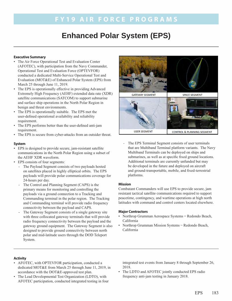
F Y 1 9 A I R F O R C E P R O G R A M S
EPS 183
integrated test events from January 8 through September 26, 2018.
• The LDTO and AFOTEC jointly conducted EPS radio frequency anti-jam testing in January 2018.
Activity• AFOTEC, with OPTEVFOR participation, conducted a
dedicated MOT&E from March 25 through June 11, 2019, in accordance with the DOT&E-approved test plan.
• The Lead Developmental Test Organization (LDTO), with AFOTEC participation, conducted integrated testing in four
Executive Summary• The Air Force Operational Test and Evaluation Center
(AFOTEC), with participation from the Navy Commander, Operational Test and Evaluation Force (OPTEVFOR) conducted a dedicated Multi-Service Operational Test and Evaluation (MOT&E) of Enhanced Polar System (EPS) from March 25 through June 11, 2019.
• The EPS is operationally effective in providing Advanced Extremely High Frequency (AEHF) extended data rate (XDR) satellite communications (SATCOM) to support submarine and surface ship operations in the North Polar Region in benign and threat environments.
• The EPS is operationally suitable. The EPS met the user-defined operational availability and reliability requirement.
• The EPS performs better than the user-defined anti-jam requirement.
• The EPS is secure from cyber-attacks from an outsider threat.
System• EPS is designed to provide secure, jam-resistant satellite
communications in the North Polar Region using a subset of the AEHF XDR waveform.
• EPS consists of four segments:- The Payload Segment consists of two payloads hosted
on satellites placed in highly elliptical orbits. The EPS payloads will provide polar communications coverage for 24-hours per day.
- The Control and Planning Segment (CAPS) is the primary means for monitoring and controlling the payloads via a ground connection to a Tracking and Commanding terminal in the polar region. The Tracking and Commanding terminal will provide radio frequency connectivity between the payload and CAPS.
- The Gateway Segment consists of a single gateway site with three collocated gateway terminals that will provide radio frequency connectivity between the payload and the gateway ground equipment. The Gateway Segment is also designed to provide ground connectivity between north polar and mid-latitude users through the DOD Teleport System.
Enhanced Polar System (EPS)
- The EPS Terminal Segment consists of user terminals that are Multiband Terminal platform variants. The Navy Multiband Terminals can be deployed on ships and submarines, as well as at specific fixed ground locations. Additional terminals are currently unfunded but may be developed in the future and deployed on aircraft and ground-transportable, mobile, and fixed-terrestrial platforms.
MissionCombatant Commanders will use EPS to provide secure, jam resistant tactical satellite communications required to support peacetime, contingency, and wartime operations at high north latitudes with command and control centers located elsewhere.
Major Contractors• Northrop Grumman Aerospace Systems ̶ Redondo Beach,
California• Northrop Grumman Mission Systems ̶ Redondo Beach,
California

F Y 1 9 A I R F O R C E P R O G R A M S
184 EPS
• AFOTEC collected reliability, availability, and maintainability data during the dedicated operational test period and additional data from January 1 through March 24, 2019.
• The Army Threat System Management Office (TSMO) planned to conduct a 6-week persistent cyber Adversarial Assessment (AA), with strong support from the EPS Program Manager; however changing schedules and limited availability truncated the effort and caused AFOTEC to re-plan the AA events.
• TSMO conducted a Close Access Team assessment from January 14 – 18, 2019, on the EPS.
• The 47th Cyber Test Squadron performed an EPS payload cyber assessment on a payload surrogate April 10 – 12, 2019.
• The 177th Information Aggressor Squadron conducted an AA from May 14 – 18, 2019.
• Air Force Space Command accepted the EPS for military operations on September 19, 2019.
Assessment• Results from the MOT&E, combined with complementary
integrated test data, were adequate to assess the operational effectiveness, suitability, and survivability of the EPS.
• The EPS is operationally effective in providing AEHF SATCOM XDR communications to support submarine and surface ship operations in the North Polar Region in benign and threat environments.
• Submarine communicators were able to acquire and logon to the EPS payloads, using either their mast or periscope antennas, and moved the Wide Focused Coverage Area beam over their location to send both voice and data messages.
• Ship communicators were able to acquire and logon to both EPS payloads and conduct Advanced Digital Network Communications point-to-point and Advanced Time Division Multiple Access Interface Processor communications.
• The USS Theodore Roosevelt (CVN 71) successfully conducted voice and data communications over EPS during the joint exercise Northern Edge 2019.
• Both ship and submarine communicators had difficulty configuring their Navy equipment properly to get it to work
over EPS. However, EPS worked well once the operators properly configured their equipment.
• When operators attempted to troubleshoot their equipment, they lacked troubleshooting guides and flowcharts.
• The help desk support for EPS communicators was inconsistent or not available. The testers often had to turn to subject matter experts from the Program Office to resolve configuration problems.
• The EPS is operationally suitable. The EPS met the user-defined operational availability and reliability requirements.
• During the testing, neither the EPS payload nor the Gateway had a critical failure. DOT&E estimates that the Mean Time Between Critical Failures (MTBCF) for these two segments is 317 percent greater than the threshold requirement. The CAPS had two critical failures that did not affect mission accomplishment.
• Both CAPS and Gateway operators felt they could use EPS to satisfy their mission requirements. Both groups felt that once trained, they were able to use EPS with ease.
• The CAPS operators thought their training and documents prepared them for their mission. The Gateway operators thought their training and documents lacked details.
• The EPS performed better than the user-defined anti-jam requirement in threat-representative testing.
• The EPS is secure from cyber-attacks from an outsider threat.
RecommendationsThe Air Force should:
1. Develop, in coordination with the Navy, an approved document that covers the end-to-end configurations, port settings, and troubleshooting flow charts for getting EPS to work with the Navy communications equipment.
2. Formalize EPS help desk procedures, including points of contacts, and publish those procedures where they are accessible to users.

F Y 1 9 A I R F O R C E P R O G R A M S
F-22A 185
capabilities. The Update 5 OFP is currently fielded in operational F-22A units.
- Increment 3.2B was a separate Major Defense Acquisition Program modernization effort that integrated AIM-120D and AIM-9X missile systems; an Enhanced Stores Management System for weapons integration and employment improvements; Intra-Flight Datalink and electronic protection enhancements; improved emitter geolocation capability; and a Common Weapon Employment Zone for air-to-air missiles employed by the F-22A. IOT&E of the 3.2B capability concluded in April 2018 and is currently being fielded.
- Update 6 is a software-only OFP effort to update the aircraft KOV-20 cryptographic module with an F-22A cryptographic architecture change to accommodate multiple, simultaneous algorithms for Link 16 datalink interoperability and secure ultrahigh frequency radio communications. Update 6 is also intended to incorporate deferred software corrections carried over from Increment 3.2B developmental testing. The Air Force intends to field Update 6 in 2020.
- F-22A Tactical Link 16 (TACLink) and Tactical Mandates (TACMAN) are hardware and software modernization efforts intended to provide Link 16 transmit capability through the Multi-functional Information Distribution System/Joint Tactical Radio System and replace the legacy Mark XVII Mode 4 Identification Friend or Foe (IFF) system with the Mode 5 IFF system.
- Originally these were separate programs; however, the Air Force has moved the acquisition of these two programs under the RAPTOR Agile Capability Release (RACR) Capability Pipeline, which is planned to release capabilities to the field on an annual basis.
Executive SummaryF-22A Update 6 is a software-only Operational Flight Program (OFP) modernization effort to update the aircraft cryptographic module with an F-22A cryptographic architecture change to accommodate multiple, simultaneous algorithms for Link 16 datalink interoperability and secure ultrahigh frequency radio communications. Update 6 is also intended to incorporate deferred software corrections carried over from Increment 3.2B developmental testing. Update 6 developmental testing began November 13, 2017, with an expected completion in spring of 2020.
System• The F-22A is an air-superiority fighter that combines low
observability to threat radars, sustained high speed, and integrated avionics sensors.
• Low observability reduces threat capability to engage F-22As with current adversary weapons.
• The aircraft maintains supersonic speeds without the use of an afterburner.
• Avionics fuses information from the Active Electronically Scanned Array radar, other sensors, and datalink information for the pilot to enable employment of medium- and short-range air-to-air missiles, guns, and air-to-ground munitions.
• The Air Force intended the F-22A to be more reliable and easier to maintain than legacy fighter aircraft.
• F-22A air-to-air weapons are the AIM-120C/D radar-guided missile, the AIM-9M/X infrared-guided missile, and the M61A2 20-mm gun.
• F-22A air-to-ground precision strike capability consists of the 1,000-pound Joint Direct Attack Munition and the 250-pound Small Diameter Bomb Increment 1.
• The F-22A program delivers capability in increments. Incremental Enhanced Global Strike modernization efforts include the following current and near-term modernization efforts:- Increment 3.1 provided enhanced air-to-ground mission
capability, to include geolocation of selected emitters, electronic attack, air-to-ground synthetic aperture radar mapping and designation of surface targets, and Small Diameter Bomb integration.
- Increment 3.2A was a software-only upgrade providing improved electronic protection, Link 16 Receive, and combat identification capabilities. Increment 3.2A is a modernization effort within the scope of the F-22A Advanced Tactical Fighter baseline acquisition program of record and is currently fielded in operational F-22A units.
- Update 5 combined an OFP upgrade providing software driven radar enhancements, Ground Collision Avoidance System software, and the incorporation of limited AIM-9X
F-22A - RAPTOR Modernization

F Y 1 9 A I R F O R C E P R O G R A M S
186 F-22A
Activity• The Air Force has not started follow-on testing documented in
the classified August 2018 DOT&E 3.2B IOT&E report. • The Air Force conducted Update 6 testing in accordance
with the agreed framework that designated the 53rd Wing to execute sustained sufficiency of test report reviews and flight operations at Nellis AFB, Nevada.
• The 59th Test and Evaluation Squadron (TES), combined with the 422nd TES and F-22A Developmental Test at Edwards AFB, California, have collaborated to accomplish over 1,287 hours and 899 sorties on Update 6.
• The Air Force plans to field Update 6 in 2020 after adjudication of multiple deficiencies that occurred during ongoing combined developmental/operational testing.
• The 59th TES will coordinate a fielding recommendation through Headquarters Air Combat Command when Update 6 testing is complete and the F-22A System Program Office assesses it as ready to go to the field.
Assessment • DOT&E is currently analyzing the results from Update 6
testing and will publish a report once developmental testing is complete.
• The Air Force must complete follow-on testing documented in the classified August 2018 DOT&E 3.2B IOT&E report. This is intended to ensure adequate completion of all testing of the new capabilities in an open-air range environment.
Recommendation1. Based on the results from 3.2B testing, the Air Force should
provide the means to conduct operational testing against an adversary air and surface threat composition needed to fully vet F-22A capabilities in open-air and high fidelity simulation venues.
- Release 1 (R1) is expected to have increments of Link 16 and IFF Mode 5 with expected fielding in late FY21 or early FY22. R2 and R3 are expected to also have increments of the original Link 16 and IFF Mode 5 F-22 programs to complete fielding of the respective capabilities.
- R1 increment of capability was due to start developmental test in October 2019, but has been delayed until spring 2020.
MissionCommanders will use units equipped with the F-22A to:
• Provide air superiority over friendly and non-permissive, contested enemy territory
• Defend friendly forces against fighter, bomber, or cruise missile attack
• Escort friendly air forces into enemy territory• Provide air-to-ground capability for counter-air, strategic
attack, counter-land, and enemy air defense suppression missions
Major ContractorLockheed Martin Aeronautics Company – Fort Worth, Texas

F Y 1 9 A I R F O R C E P R O G R A M S
FAB-T 187
• On May 21, 2019, USSTRATCOM requested early operational use of FAB-T prior to the Air Force Space Command (AFSPC)
Activity• SAF/AQ (Milestone Decision Authority) approved an increase
to the total Low-Rate Initial Production quantity from 53 to 84 FAB-T CPT terminals on February 7, 2019.
will use FAB-T to provide strategic nuclear and non-nuclear command and control with extremely high frequency, wideband, protected, and survivable communications terminals for beyond line-of-sight communications.
• Air Force Space Command (AFSPC) will use the FAB-T to perform satellite telemetry, tracking, and commanding (TT&C) functions for the AEHF constellation, including management of the satellites, communication networks, and cryptologic keys.
• USSTRATCOM and U.S Northern Command will use the FAB-T to provide Integrated Tactical Warning and Attack Assessment satellite communications of incoming missile threats to military forces from fixed and mobile sites.
Major ContractorRaytheon Space and Airborne Systems – Marlborough, Massachusetts
Family of Advanced Beyond Line-of-Sight Terminals (FAB-T)
Executive Summary• The Assistant Secretary of the Air Force, Acquisition,
Technology and Logistics (SAF/AQ) increased the Low-Rate Initial Production purchase to include all 84 planned terminals in February 2019.
• The U.S. Strategic Command (USSTRATCOM) obtained early operational use of FAB-T in June 2019, allowing use of the FAB-T on operational networks for operations, during test events, and USSTRATCOM exercises. USSTRATCOM operators and testers are using Family of Advanced Beyond Line-of-Sight Terminals (FAB-T) to test and identify deficiencies that the Program Management Office (PMO) must fix before the terminals are usable at operational sites planned for installation in FY20.
• Testers discovered additional deficiencies during Integrated Developmental Testing and Evaluation (IDT&E) in June through December 2019. Raytheon and the PMO are developing software fixes for the deficiencies USSTRATCOM requires to be fixed to support operations.
• The Air Force Test and Evaluation Test Center (AFOTEC) began IOT&E in October 2019, evaluating the system in benign and threat-representative environments.
System• FAB-T consists of ground and aircraft communication
terminals with two terminal types: Command Post Terminals (CPTs) and Force Element Terminals (FETs). FAB-T is part of the terminal and control segments of the Advanced Extremely High Frequency (AEHF) satellite system and is designed to operate with AEHF Low Data Rate and Extended Data Rate waveforms.
• The CPT will replace existing airborne (E-4B and E-6B), ground-fixed, and ground-transportable Milstar CPTs. The CPT will include satellite and network control functions, end-user telecommunication device interfaces, and the ability to operate the terminal from a distant location using a remote node.
• The FET is intended to be installed in airborne force elements (B-52 and RC-135).
Mission• The President, the Secretary of Defense, Combatant
Commanders, and supporting Air Force component forces

F Y 1 9 A I R F O R C E P R O G R A M S
188 FAB-T
Operational Trial Period and IOT&E to support FAB-T events. AFSPC approved the USSTRATCOM request on June 3, 2019.
• The Program Executive Officer certified FAB-T ready for dedicated IOT&E on August 23, 2019, and deferred evaluation of ground transportable CPT suitability until FOT&E.
• DOT&E approved the FAB-T CPT IOT&E test plan on August 28, 2019. AFOTEC intends to conduct the IOT&E in two phases. - Phase one tests FAB-T in benign operational environments,
started in October 2019, and includes the IDT&E data. Phase one uses FAB-T developmental software versions fielded for early operational use.
- Phase two is expected to use updated FAB-T software, which will include deficiency corrections required by USSTRATCOM. Phase two is planned to start in December 2019 and includes testing in benign, threat, contested, and cyber environments.
• USSTRATCOM and AFSPC commenced FAB-T early operational use at five sites during 4QFY19 and 1QFY20.
• The Air Force Plans to start development of the FAB-T FET in FY20. SAF/AQ designated FAB-T FET as a middle tier of acquisition program using a Rapid Prototyping Strategy.
Assessment• The FAB-T PMO has made progress resolving FAB-T
deficiencies; however, new deficiencies continue to be discovered with new software builds. Most deficiencies occur when the terminals are logged onto operational networks because the test networks and simulations do not emulate the variety or number of legacy terminals with which FAB-T must work.
• USSTRATCOM is supporting the use of FAB-T on operational networks for testing during day-to-day operations and during exercises. This allows for stressing the FAB-T at
exercise-level operational conditions that cannot be created in the laboratory and allows early operator involvement and feedback. This approach enables the identification of deficiencies that USSTRATCOM or AFSPC require be corrected before transition from legacy terminals to the FAB-T for NC3 or TT&C operations.
• The Air Force’s threat emulators representing nuclear scintillation effects and threat-representative downlink jamming effects planned for IOT&E are behind schedule.
• The uplink jammer will not be available until FOT&E in FY21.
• The PMO is behind schedule delivering the FAB-T capability due to delays in resolving software deficiencies and the continued identification of new software deficiencies.
• Extended Data Rate capability, Presidential and National Voice Conferencing capability, the new FAB-T Airborne antenna, representative airborne platforms (E-4B and E-6B) employing the FAB-T, and the operationally representative CPT with a ground transportable antenna will not be ready before the end of FAB-T IOT&E. Operational evaluation of these capabilities will be accomplished during FOT&E.
RecommendationsThe PMO should:
1. Update the FAB-T Test and Evaluation Master Plan (TEMP) to address the testing that will be delayed to an FOT&E and for the correction of deficiencies.
2. Begin the planning for the FAB-T FET and complete the FET TEMP.
3. Include resources and funding in the FAB-T and FET TEMP for the development and use of threat emulation for testing.

F Y 1 9 A I R F O R C E P R O G R A M S
GPS 189
Executive Summary• Ongoing schedule slips for all GPS segments have caused
operational testing delays from dates listed in prior DOT&E Annual Reports. The Air Force plans to conduct operational testing of the GPS Enterprise in 2020.
• The Air Force conducted developmental test and evaluation (DT&E) for all three GPS enterprise segments (space, control, and user) in 2019. DT&E included the GPS III Satellite Vehicle (SV) 01 On-Orbit Checkout Test, Next Generation Operational Control System (OCX) Block 1 testing, and Military GPS User Equipment (MGUE) Increment 1 circuit card testing.
• While the Air Force has made progress across the segments, significant GPS Enterprise operational risks remain: - More work is needed to comprehensively replicate space
threats, their effect on the space segment, mitigation efforts, and the strategy to conduct operational space segment testing using realistic threats.
- The MGUE program continues to experience delays integrating the new technology into the lead platforms and in developing final software and hardware builds by MGUE vendors.
- Ongoing schedule slips with MGUE lead platform testing increases integration risks for non-lead platforms seeking to implement MGUE before lead platform testing is complete.
System• The GPS enterprise is an Air Force-managed, satellite-based
radio navigation system of systems that provides military and civil users accurate position, velocity, and time within the Earth atmosphere, space, and worldwide Earth surface areas.
• The current GPS enterprise consists of three operational segments: - Space Segment – The GPS spacecraft constellation
consists of satellites in semi-synchronous orbit. The Air Force has successfully launched 72 GPS satellites and currently operates 31 operational GPS satellites. The operational constellation is comprised of Block IIR (1997-2004), Block IIR-M (2005-2009), and Block IIF (2010-2016). The GPS III satellite (SV01) is in orbit and is now available to operationally join the GPS constellation pending planned upgrades to the Control Segment.
- Control Segment – The GPS control segment consists of primary and backup GPS master control stations, satellite ground antennas, a pre-launch satellite compatibility station, and geographically distributed monitoring/tracking stations. The GPS control segment includes: ▪ The Operational Control System (OCS)/Architecture
Evolution Plan, which supports operations of the current satellite constellation
Global Positioning System (GPS) Enterprise
▪ The Launch and Checkout Capability (LCC)/Launch and Checkout System (LCS) (also known as OCX Block 0), which launches and initializes GPS III satellites
▪ The Selective Availability/Anti-Spoof Module (SAASM) Mission Planning System (SMPS), which provides mission planning capability in the Combined Space Operations Center
- User Segment – There are many versions of military GPS mission receivers fielded on a multitude of operational systems and combat platforms, including the Defense Advanced GPS Receivers and embedded Ground-Based GPS Receiver Application Modules (GB-GRAM). These military GPS mission receivers provide secure position, navigation, and timing for both the U.S. and allied/partner nations.
• In 2000, the Air Force initiated a GPS enterprise modernization effort to include upgrades to all three segments, along with new civil and military signals (M-code). In addition to replenishment of the satellite constellation, this modernization will improve both military and civil signal integrity and service quality. Modernized GPS enterprise improvements include:- Space Segment – The Air Force intends for the GPS III
satellites to deliver better accuracy and provide improved anti-jamming capabilities, transmit a fourth civil signal to enable interoperability with other international global navigation satellite systems, higher powered M-code for military use, as well as all legacy military and civil navigation signals of previous satellite blocks. The Air Force plans for 10 GPS III satellites and subsequently 22 GPS III Follow-On Production (GPS IIIF) satellites. GPS IIIF will have enhancements, such as regional

F Y 1 9 A I R F O R C E P R O G R A M S
190 GPS
military protection, support for search and rescue services, and laser retro-reflector arrays for better on-orbit position determination.
- Control Segment – The Air Force plans to deliver OCX, an Acquisition Category ID program, in several increments. OCX will replace OCS and LCC/LCS, be backward compatible with legacy and modernized satellites, and interface with updated SMPS versions. OCX Block 0 launches and initializes GPS III satellites, while OCX Block 1 will command and control GPS Block II and III satellites. OCX Block 2 (now merged and scheduled concurrently with OCX Block 1 delivery) will provide full control of modernized civil and M-code signals and navigation warfare functions. OCX is intended to provide significant cybersecurity improvements over OCS. OCX Block 3F will fly the GPS IIIF spacecraft once available.
- User Segment – MGUE Increment 1 includes the GB-GRAM-Modernized form factor for ground and low dynamic platforms and the GRAM-Standard Electronic Module-E/Modernized for maritime and aviation applications. The Air Force approved MGUE Increment 2 in November 2018 as two separate Middle Tier of Acquisition/Section 804 programs of record. Under MGUE Increment 2, the Air Force will develop (1) the Miniaturized Serial Interface form factor with a smaller Next Generation Application-Specific Integrated Circuit (ASIC) as core GPS receiver technology to support low-power applications, such as guided munitions, and address ASIC obsolescence; and (2) the joint modernized handheld receiver end-item, which improves anti-jam and anti-spoof during acquisition and tracking, as well as longer battery life.
• Due to delays in OCX Block 1 delivery, the Air Force initiated the GPS III Contingency Operations (COps) program as a “bridge capability”/risk mitigation effort to enable employment of GPS III satellites using legacy (pre-M-code) signals for operational constellation sustainment until OCX is delivered. Additionally, M-code Early Use (MCEU) will deliver early operational use of core M-code, with full M-code functionality delivered in OCX Blocks 1 and 2.
MissionCombatant Commanders of U.S. and allied military forces use GPS to provide accurate position, navigation, and time information to operational users worldwide. GPS also supports a myriad of non-military users worldwide.
Major Contractors• Space Segment
- Block IIR/IIR-M/III/IIIF satellites: Lockheed Martin Space Systems – Denver, Colorado
- Block IIF satellites: Boeing, Network and Space Systems – El Segundo, California
• Control Segment- OCS, COps, and MCEU: Lockheed Martin Space Systems
Division – Denver, Colorado - OCX: Raytheon Company, Intelligence, Information,
and Services – Aurora, Colorado• User Segment (MGUE Increment 1)
- L3Harris Technologies, Inc. – Melbourne, Florida - Raytheon Company, Space and Airborne Systems –
El Segundo, California- Collins Aerospace – West Palm Beach, Florida
two-phase GPS Enterprise Multi-Service OT&E (MOT&E) that will include OCX and GPS III. This will inform both the Positioning, Navigation, and Timing Initial Operating Capability (IOC) as well as the Constellation Management IOC. Testing will be conducted to support OCX Operational Acceptance following transition of constellation control from OCS to OCX, followed by full-M-code MOT&E to include M-code User segment systems.
GPS III COps • AFOTEC is planning operational testing of COps in
2020, concurrent with GPS III SV01 operational testing, to support COps Operational Acceptance later that year. Integrated system testing for COps began in 2019.
MCEU • AFOTEC plans to conduct operational testing of MCEU in
2020. Control Segment testing will include the worldwide distributed GPS M-code capable monitoring stations.
Activity• Schedule slips have caused operational testing delays for all
GPS segments from dates listed in prior DOT&E Annual Reports. The Air Force plans to begin operational testing of the space, ground, and user segments in 2020.
• In FY19, the Air Force conducted DT&E for all three GPS enterprise segments (space, control, and user). Testing included the GPS III SV01 Mission Readiness Test and On-Orbit Checkout Test, OCX Block 1 testing, and MGUE Increment 1 card testing.
• The Program Office is working on additional revisions to the Enterprise Test and Evaluation Master Plan to address an updated space threat strategy, cyber testing, concurrent delivery of OCX Blocks 1 and 2, MGUE Increment 2, upgraded Nuclear Detonation Detection System control system, GPS IIIF, and OCX Block 3F. OCX• The Air Force Operational Test and Evaluation Center
will conduct OT&E of OCX in 2022 as the first of a

F Y 1 9 A I R F O R C E P R O G R A M S
GPS 191
GPS III and GPS III Follow-On Production • The Air Force successfully launched the first (SV01) of 10
GPS III satellites into orbit on December 23, 2018. It has undergone successful checkout and is now available to operationally join the GPS constellation upon planned upgrades to the Control Segment. The second satellite launched on August 22, 2019, and the third is scheduled for early 2020.
• The Air Force contracted Lockheed Martin to build 22 GPS IIIF satellites in 2018. The first IIIF will be available for launch (AFL) no later than 2028, but current estimates forecast AFL in 2026.
MGUE• In 2018, the Air Force Service Acquisition Executive
approved the MGUE Increment 2 acquisition strategy. This approval resulted in the release of a draft Request for Proposal announcement for the MGUE Increment 2 receiver card in 2019.
• Ground-based developmental field testing of MGUE card maturity in 2019 will inform MGUE card development and support preparations for MGUE lead platform developmental field testing scheduled to begin in 2020. The Air Force terminated the airborne developmental field test in 2019 early due to a fire in the test airframe. MGUE Lead Platform OT&E will include data collection from separate MGUE Increment 1 Operational Utility Evaluations on the four designated Service lead platforms. MGUE OT&E will be followed by the two-phase GPS Enterprise MOT&E in 2022 and 2023. The second phase of the MOT&E will incorporate user equipment, both lead and non-lead platforms.
Assessment• The Air Force has improved the GPS Enterprise schedule
by addressing schedule and performance risks; however, articulation of program risks with stakeholders continues to be incomplete, increasing the probability of unmitigated risks causing further program problems and delays.
• The Lead Developmental Test Organization is effectively managing the breadth of developmental testing activities, emerging test requirements, and significant changes to test plans. OCX and COps/MCEU • Delays in COps software delivery have driven increasingly
tight and compressed testing schedules. The deployment of
sustainment software immediately after COps OT&E and operational acceptance will result in a lack of time to fix major discrepancies that testing uncovers.
GPS III and GPS IIIF • GPS III lacks a testing plan with adequate space threat
representation. The Program Office plans to conduct environmental testing, but it is not currently planning for sufficient test articles to support full characterization of adversary threats against the system.
• The Air Force has proposed a Milestone C decision in 2020, prior to development or testing of any GPS IIIF satellites. The first GPS IIIF is currently scheduled for launch in 2026-2028.
MGUE• The first MGUE card has been completed. It was verified
by the government in 2019 and all associated discrepancies will be addressed in future updates. The MGUE program continues to face challenges meeting technical requirements with some cards, resulting in delays to development of final software and hardware builds by some MGUE vendors.
• The ongoing delays of final software and hardware builds by MGUE vendors continue to cause delays to MGUE lead platform test schedules, which increases the risk for platforms seeking to implement MGUE before lead platform testing is complete. The utility of the lead platforms to act as pathfinders will also diminish due to these delays. Lead platform test schedule slips also increase risk for the DOD because non-lead platforms might delay ordering MGUE cards. The MGUE trusted foundry production lines are scheduled to shut down due to the GPS Programs’ use of now obsolete ASIC technologies.
RecommendationsThe Air Force should:
1. Conduct operational testing of the GPS Enterprise against current and emerging space threats, to assess the ability of the system and its operators to support DOD missions in a contested space environment.
2. Inform users of GPS across the DOD of GPS Enterprise test results and schedule delays, to enable users to plan for integration of new GPS capabilities.

192
F Y 1 9 A I R F O R C E P R O G R A M S
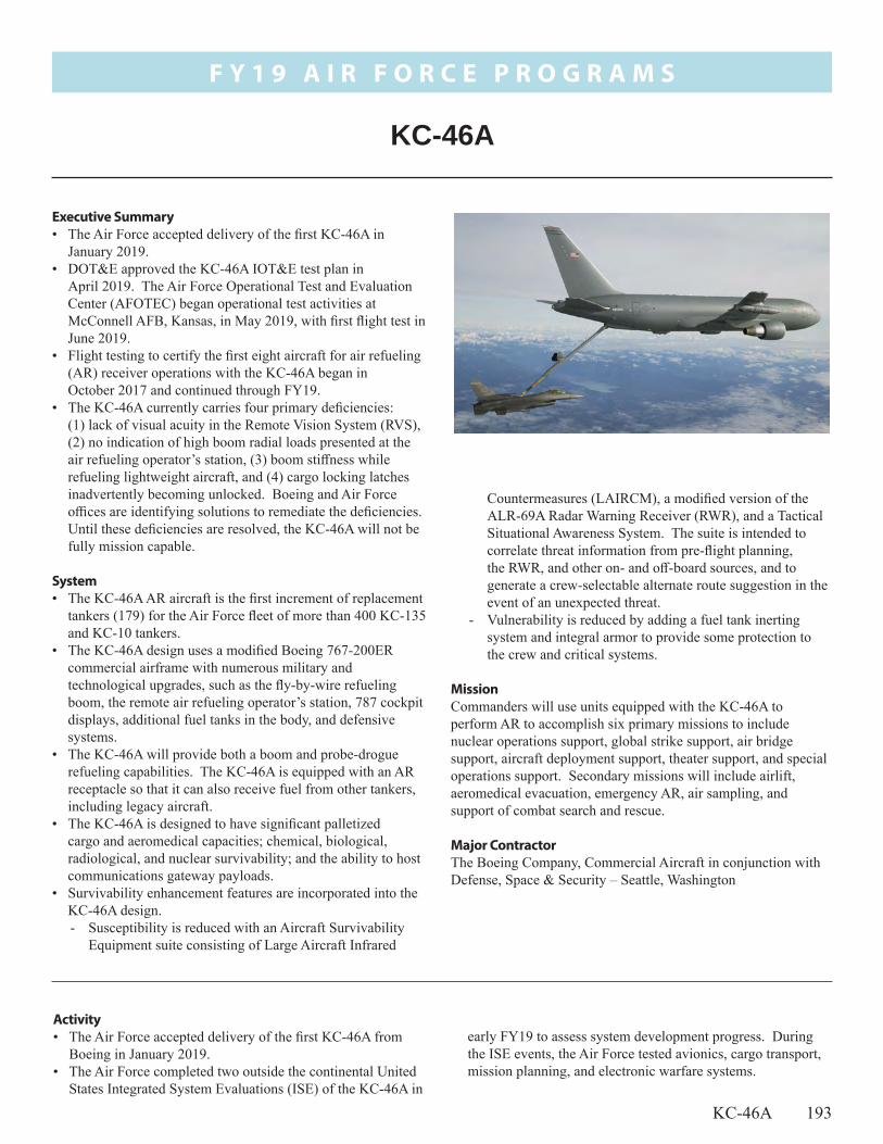
F Y 1 9 A I R F O R C E P R O G R A M S
KC-46A 193
early FY19 to assess system development progress. During the ISE events, the Air Force tested avionics, cargo transport, mission planning, and electronic warfare systems.
Activity• The Air Force accepted delivery of the first KC-46A from
Boeing in January 2019.• The Air Force completed two outside the continental United
States Integrated System Evaluations (ISE) of the KC-46A in
Countermeasures (LAIRCM), a modified version of the ALR-69A Radar Warning Receiver (RWR), and a Tactical Situational Awareness System. The suite is intended to correlate threat information from pre-flight planning, the RWR, and other on- and off-board sources, and to generate a crew-selectable alternate route suggestion in the event of an unexpected threat.
- Vulnerability is reduced by adding a fuel tank inerting system and integral armor to provide some protection to the crew and critical systems.
MissionCommanders will use units equipped with the KC-46A to perform AR to accomplish six primary missions to include nuclear operations support, global strike support, air bridge support, aircraft deployment support, theater support, and special operations support. Secondary missions will include airlift, aeromedical evacuation, emergency AR, air sampling, and support of combat search and rescue.
Major ContractorThe Boeing Company, Commercial Aircraft in conjunction with Defense, Space & Security – Seattle, Washington
Executive Summary• The Air Force accepted delivery of the first KC-46A in
January 2019.• DOT&E approved the KC-46A IOT&E test plan in
April 2019. The Air Force Operational Test and Evaluation Center (AFOTEC) began operational test activities at McConnell AFB, Kansas, in May 2019, with first flight test in June 2019.
• Flight testing to certify the first eight aircraft for air refueling (AR) receiver operations with the KC-46A began in October 2017 and continued through FY19.
• The KC-46A currently carries four primary deficiencies: (1) lack of visual acuity in the Remote Vision System (RVS), (2) no indication of high boom radial loads presented at the air refueling operator’s station, (3) boom stiffness while refueling lightweight aircraft, and (4) cargo locking latches inadvertently becoming unlocked. Boeing and Air Force offices are identifying solutions to remediate the deficiencies. Until these deficiencies are resolved, the KC-46A will not be fully mission capable.
System• The KC-46A AR aircraft is the first increment of replacement
tankers (179) for the Air Force fleet of more than 400 KC-135 and KC-10 tankers.
• The KC-46A design uses a modified Boeing 767-200ER commercial airframe with numerous military and technological upgrades, such as the fly-by-wire refueling boom, the remote air refueling operator’s station, 787 cockpit displays, additional fuel tanks in the body, and defensive systems.
• The KC-46A will provide both a boom and probe-drogue refueling capabilities. The KC-46A is equipped with an AR receptacle so that it can also receive fuel from other tankers, including legacy aircraft.
• The KC-46A is designed to have significant palletized cargo and aeromedical capacities; chemical, biological, radiological, and nuclear survivability; and the ability to host communications gateway payloads.
• Survivability enhancement features are incorporated into the KC-46A design. - Susceptibility is reduced with an Aircraft Survivability
Equipment suite consisting of Large Aircraft Infrared
KC-46A

F Y 1 9 A I R F O R C E P R O G R A M S
194 KC-46A
• Flight testing to certify the first eight aircraft for AR receiver operations with the KC-46A began in October 2017 and continued through FY19.
• The KC-46A program attained AR certifications for boom refueling the F-16, F-15, C-17, B-52, and KC-46A and centerline drogue refueling the F/A-18C/D. The A-10 and F/A-18E/F receiver certifications were delayed due to technical and scheduling difficulties.
• AFOTEC began operational test activities at McConnell AFB, Kansas, in May 2019 in accordance with the DOT&E-approved test plan.
• The Air Force conducted a Cooperative Vulnerability and Penetration Assessment in 4QFY19.
• Operational data collection and analysis is ongoing.• Boeing and the Air Force are exploring options to resolve the
four primary system deficiencies: (1) lack of visual acuity in the RVS, (2) no indication of high boom radial loads presented at the air refueling operator’s station, (3) boom stiffness while refueling light-weight aircraft, and (4) cargo locking latches inadvertently becoming unlocked.
• The KC-46A program completed thermal curtain materials qualification testing in June 2019 at Sandia National Laboratories to support the manufacture of thermal curtains for crew survivability to nuclear threats.
• Air Force analyses are ongoing to assess the KC-46A inherent nuclear hardness to blast, radiation, flash, thermal, and
electromagnetic pulse effects and to assess base safe escape in the event of a nuclear attack.
• The Air Force is coordinating with the Defense Threat Reduction Agency on future testing of KC-46A against operationally realistic electromagnetic pulse effects. The Defense Threat Reduction Agency will provide funds and test plans to support continuous wave and electromagnetic pulse testing expected to occur in FY20.
Assessment• Operational testing has verified deficiencies observed during
developmental testing for the RVS during AR operations.• Until the stiff boom deficiency is resolved, lightweight receiver
aircraft will have difficulties refueling from the KC-46A.• Until the cargo lock deficiency is resolved, flight operations
requiring cargo pallets will not be allowed to occur.• Schedule analysis identified the completion date for IOT&E
will have two key drivers: (1) certification and testing of all 18 receiver aircraft planned to participate in IOT&E, and (2) delivery of production-representative wing air refueling pods for operational testing.
Recommendation1. The KC-46A program should advocate for any changes
necessary to ensure the RVS is mission capable under all expected air refueling conditions.

F Y 1 9 A I R F O R C E P R O G R A M S
RQ-4B 195
the DOT&E-approved test plan. However, due to attempting to remain on the Air Combat Command (ACC) early fielding schedule, AFOTEC did not accomplish all of the imagery
Activity• AFOTEC conducted the RQ-4B Global Hawk Block
30 MS-177 OUE from June through September 2019. AFOTEC conducted most of the testing in accordance with
exercise for the development and fielding of the full 10-band sensor.
• The RQ-4B Block 30 MS Intelligence program added the Goshawk network and Swift Broadband to the Global Hawk system. The Goshawk network is a new way to utilize the Ku Satellite system and operators use the network for aircraft and sensor command and control, as well as imagery and signal dissemination. The new Swift Broadband assists operators with weather radar activities and adds an additional air traffic control voice communication path.
• The Air Force – Distributed Common Ground System (AF DCGS) supports ISR collection, processing, exploitation, analysis, and dissemination for the Global Hawk Block 30 system. The AF-DCGS employs global communications architecture to connect multiple intelligence platforms and sensors to numerous DCGS installations where intelligence analysts produce and disseminate intelligence products.
• The Air Force has taken delivery of all 21 RQ-4B Block 30 air vehicles along with 9 Mission Control and 10 Launch and Recovery ground stations. Each Launch and Recovery ground station controls one air vehicle.
MissionCommanders use RQ-4B Global Hawk reconnaissance units to provide high-altitude, long-endurance intelligence collection capabilities to support theater operations.
Major ContractorNorthrop Grumman Aerospace Systems, Strike and Surveillance Systems Division – San Diego, California
Executive Summary• The Air Force Operational Test and Evaluation Center
(AFOTEC) conducted the Operational Utility Evaluation (OUE) for the RQ-4B Global Hawk Block 30 Multi-Spectral (MS) – 177 from June through November 2019. Based on preliminary analysis, the system demonstrated the capability to provide electro-optical (EO) and infrared (IR) imagery data. The sensor can support long-endurance missions necessary to support operations at a peacetime or a non-crisis operational tempo. Although the system did not meet all of the joint interoperability requirements, it did not significantly degrade mission effectiveness.
• The Air Force conducted a Cooperative Vulnerability and Penetration Assessment (CVPA) in conjunction with the OUE. It identified vulnerabilities that will be documented in the classified DOT&E OUE report. The report is expected to be available March 2020.
System• The RQ-4B Global Hawk is a remotely piloted, high-altitude,
long-endurance airborne intelligence, surveillance, and reconnaissance (ISR) system that includes the Global Hawk unmanned air vehicle, various intelligence and communications relay mission payloads, and supporting command and control ground stations.
• The RQ-4B Global Hawk Block 30 system is equipped with a multi-intelligence payload that includes both the Enhanced Integrated Sensor Suite (E-ISS) imagery intelligence payload and Airborne Signals Intelligence Payload (ASIP) sensor. The Air Force has retrofitted two Block 30 aircraft with the 7-band MS-177 sensor, in-place of the E-ISS to provide high resolution MS imaging capability with accurate and automatic geolocation capabilities at high stand-off ranges.
• The RQ-4B Block 30 MS Intelligence program replaces the E-ISS with a 10-band multi-spectral sensor referred to as MS-177A while retaining the ability to operate ASIP concurrently. The MS-177A sensor is capable of generating multi-spectral images that combine the expanded visible and IR ranges to provide a unique and highly exploitable form of intelligence. The Air Force is conducting an early fielding of two 7-band multi-spectral sensors, known as MS-177, to enhance immediate capabilities and serve as a risk reduction
RQ-4B Global Hawk High-Altitude Long-Endurance Unmanned Aerial System (UAS)
F Y 1 9 A I R F O R C E P R O G R A M S
196 RQ-4B
testing documented in the test plan. DOT&E is analyzing the OUE test data and intends to produce a classified report in March 2020.
• ACC plans to field two aircraft with the MS-177 sensor installed to support Combatant Command operations in 2QFY20.
• AFOTEC conducted the CVPA in conjunction with the OUE. The vulnerabilities identified in the CVPA will be documented in the classified DOT&E OUE report.
Assessment• Based on preliminary analysis, the system demonstrated
the capability to provide EO and IR imagery data. The sensor can support long-endurance missions necessary to support operations at a peacetime or a non-crisis operational
tempo. Although the system did not meet all of the joint interoperability requirements, it did not significantly degrade mission effectiveness.
• Implementation of the Goshawk network architecture and Swift Broadband added system complexity that resulted in increased datalink outages.
• Any datalink bandwidth restrictions may result in the system not being suitable for some sensor modes, such as persistent imaging.
Recommendation1. The Air Force should correct RQ-4B Global Hawk
Block 30 MS-177 sensor vulnerabilities discovered during the OUE to improve system survivability.

F Y 1 9 A I R F O R C E P R O G R A M S
SDB II 197
to hardware failures and 1 additional release, at DOT&E’s request, based on a previously failed maritime target mission during GCT.
• During MOT&E Phase I, the Target Data Scoring Board (TDSB) assessed 3 weapons as no tests due to test
Activity• The Air Force MOT&E Phase I operational test flights using
the F-15E began in June 2018 and completed in May 2019. In total, the F-15E released 59 weapons, encompassing 43 NA, 8 CA, and 8 LIA missions. The program flew the test plan-required 56 releases plus 2 additional releases due
• In addition to a GPS and an Inertial Navigation System, to achieve precise guidance accuracy in adverse weather, the SDB II employs the multi-mode seeker, equipped with a millimeter-wave radar, imaging infrared sensor, and a semi-active laser guidance sensor.
• The Normal Attack (NA) mode is used primarily to strike mobile targets in adverse weather. The Laser Illuminator Attack (LIA) mode is used to guide the weapon to a laser spot generated by the launching aircraft or a third party source. The Coordinate Attack (CA) mode is used primarily to strike stationary targets and can be used in adverse weather.
• The SDB II incorporates a multi-function warhead (blast, fragmentation, and shaped-charge jet) designed to defeat armored and non-armored targets. The weapon can be set to initiate on impact, at a preset height above the intended target, or in a delayed mode.
• An SDB II-equipped unit or Joint Terminal Attack Controller (JTAC) will engage targets in dynamic situations and use a weapon datalink network to provide in-flight target updates, in-flight retargeting, weapon in-flight tracking, and if required, weapon abort.
MissionCombatant Commanders will use units equipped with the SDB II to attack stationary and moving ground and littoral targets in adverse weather conditions at standoff ranges.
Major ContractorRaytheon Missile Systems – Tucson, Arizona
Executive Summary• The Air Force began Multi-Service Operational Test and
Evaluation (MOT&E) Phase I flight testing and live fire testing of the Small Diameter Bomb (SBD) II on the F-15E in June 2018, conducting a total of 31 drops in FY18. The Air Force conducted an additional 28 drops and completed MOT&E Phase I flight tests in May 2019. The Air Force plans to complete Integrated Flight Simulation (IFS) data validation and collection of additional cybersecurity data in FY20, which will complete the remaining tasks of MOT&E Phase I.
• MOT&E Phase I flight test missions built upon the capabilities demonstrated in Government Confidence Testing (GCT). This included demonstrating the ability to successfully engage a target with multiple weapons on a single pass, operate in all modes in a GPS-jamming environment, perform a commanded abort, employ an exclusion zone, and override the exclusion zone to engage a target.
• The Air Force awarded the Low-Rate Initial Production Lot 5 contract for 1,260 weapons (510 Air Force, 750 Navy) in December 2018.
• The Navy intends to begin operational testing (OT) using the F/A-18E/F in FY20. MOT&E Phase II will begin in FY21 and continue through FY22 with the Navy conducting flight testing using the F-35. The program will accomplish a Full-Rate Production decision upon completion of F-35 testing.
• Analysis of SDB II accuracy and lethality are ongoing. Initial analysis of MOT&E Phase I data shows that modifications made as a result of findings from GCT and developmental test have improved performance.
• The Air Force is advocating for operationally representative initiatives to streamline the cryptographic information delivery, loading, and verification process. The current process adversely affects the ability to employ the SDB II at standoff range.
System• The SDB II is a 250-pound, air-launched, precision-glide
weapon that uses deployable wings to achieve standoff range. • The Air Force directed design of the SDB II to achieve the
capabilities deferred from SDB I. Capability improvements include: a weapon datalink and multi-mode seeker.
• The weapon datalink allows post-launch tracking and control of the weapon, which provides standoff employment capability.
Small Diameter Bomb (SDB) II

F Y 1 9 A I R F O R C E P R O G R A M S
198 SDB II
artificialities and 11 weapons as having experienced a free flight reliability failure, leaving 45 weapons employed reliably. Faulty guidance inputs provided by an unfielded and non-operationally representative JTAC system induced two of the free flight reliability failures, leading DOT&E to consider them no tests. This does not change the TDSB scoring. Based on the above, MOT&E Phase I demonstrated free flight reliability of 45 successes, 9 failures, and 5 no tests.
• The nine failures included: - An Inertial Measurement Unit (IMU) gyro failure- A dome failure after the ejected dome cover contacted the
dome- Two instances of an electrical transient occurring after the
dome cover was ejected- Two different cryptographic software problems- Three different algorithm/seeker problems that led to
inadequate performance during those particular missions • The program identified the root cause for all failures
except the IMU gyro failure, analysis of which is ongoing. Additionally, the program is finalizing a change to the dome cover deployment logic to address the problem of the dome cover contacting the dome after ejection. The program has incorporated fixes to all other failure modes in the next weapon software release.
• During MOT&E Phase I, the Program Office completed 20 rounds of seeker captive flight tests (CFTs), resulting in over 2,260 target runs in a wide variety of terrain and environmental conditions. These tests logged over 483 hours of seeker operation without any failures.
• The program augmented the IFS model by incorporating the results of the 2,260 CFT runs as well as weapon flight tests. Raytheon released its IFS model verification and validation report in July 2017, and the Air Force Operational Test and Evaluation Center (AFOTEC) gave initial accreditation for its use during OT. Upon receipt of all Air Force MOT&E validation data from Phase I, AFOTEC will be able to make a final accreditation decision, which would allow a determination regarding SDB II operational effectiveness.
• Captive carry reliability testing (CCRT) is complete with over 2,000 hours of ground reliability testing and over 2,320 hours of flight test. The program will continue to collect captive hours during the Production Reliability Incentive Program that began with Lot 2 production-representative assets.
• The program redesigned the Air Turbine Alternator (ATA), which provides power to the SDB II fuse, to address a deficiency identified during a CFT failure. No ATA failures occurred during MOT&E Phase I.
• The Air Force collected cybersecurity test data during a Cooperative Vulnerability and Penetration Assessment in December 2018, and an Adversarial Assessment in February 2019.
• The Air Force collected cybersecurity test data from the Weapons System Simulator (WSS) and the Richter Laboratory F-15E bus emulator in July 2019. AFOTEC has not accredited the WSS as adequate for operational evaluation purposes because they were unable to gain the necessary verification
and validation data from Raytheon within the FY18-19 MOT&E Phase I timeline and funding limitations.
• AFOTEC hosted a Sandia National Laboratory (SNL) Red Team at the Raytheon hardware-in-the-loop laboratory in September 2019. The SNL Red Team will publish a report of their analysis of seeker attack vectors in CY20.
• The Air Force awarded the Low-Rate Initial Production Lot 5 contract for 1,260 weapons (510 Air Force, 750 Navy) in December 2018.
• The Navy intends to conduct OT in FY20 to verify SDB II integration on the F/A-18E/F. The Navy is scheduled to conduct MOT&E Phase II in FY21 and FY22 on the F-35B and F-35C to further characterize its operational effectiveness against small boats, and to evaluate carrier/shipboard operability. Phase II will also include CFTs to provide additional data for employment against maritime targets.
• With the exception of accrediting the WSS, the Air Force conducted MOT&E Phase I testing in accordance with the DOT&E-approved Milestone C Test and Evaluation Master Plan (TEMP) and test plan.
• DOT&E intends to publish an MOT&E Phase I F-15E Early Fielding Report expected in 3QFY20.
• The Air Force and Navy are in the process of updating the Milestone C TEMP based on the results of MOT&E Phase I. This update will drive the specifics of F/A-18E/F OT and MOT&E Phase II.
Assessment• MOT&E Phase I flight test missions built upon the capabilities
demonstrated in GCT by showing the ability to successfully engage a target with multiple weapons on a single pass, operate in all modes in a GPS-jamming environment, perform a commanded abort, and both employ an exclusion zone and override the exclusion zone to engage a target.
• In the CA mode, the system performed as expected with all weapons hitting at appropriate distances from the planned coordinates provided to the weapon. In the LIA mode, all weapons hit in very close proximity to the directed laser spot.
• SDB II performance in NA mode continues to improve. - During GCT, the program implemented software
improvements and modified employment procedures to correct deficiencies when engaging static targets in certain environments. MOT&E Phase I flight test missions confirmed the software improvements and modified employment procedures improved SDB II performance against static targets.
- The weapon performs well in NA mode against moving targets if it receives valid targeting data. Two factors affected the weapon receiving valid targeting data during MOT&E Phase I: the cumbersome process for loading Link 16 datalink cryptographic information and the lack of a DOD standard JTAC ultrahigh frequency (UHF) datalink kit. ▪ The process to load Link 16 datalink cryptographic
information is cumbersome due to Net-Enabled Weapons
F Y 1 9 A I R F O R C E P R O G R A M S
SDB II 199
Handling Guidance requirements, which requires the cryptographic information be parsed out and hand-loaded to ensure security. There is no way to verify if the cryptographic information on the aircraft, weapons, and mission planning systems are valid and compatible with the datalink until mission time. During MOT&E, the program mitigated this limitation by developing and fielding Network Entry System Test (NEST) software, which advises the aircrew prior to launch as to whether all cryptographic information is loaded properly and compatible with the datalink. Additionally, subject matter experts reviewed datalink cryptographic information prior to launch. However, the NEST software is not operationally adequate and subject matter expert review is not operationally sustainable. Additional initiatives to streamline cryptographic information delivery, loading, and verification are required for SDB II to be effectively employed in standoff mode.
▪ During testing, JTACs used multiple different UHF datalink kits. The lack of JTAC familiarity with the different kits, particularly their ability to ensure the kit was compatibly keyed to transmit data to the weapon, resulted in incorrect targeting data being passed to the weapon.
• Mission planning is also a significant challenge, with average planning times of over 50 minutes per weapon (the threshold time is 5 minutes per weapon). Much of this is related to a time intensive, error prone cryptographic data entry process, and a poor exclusion zone creation process.
• Weapons with the production-representative software version 7 demonstrated a reliability that is slightly below the threshold required at this stage of the program, but does mark a considerable improvement from early testing. The Program Office anticipates that the next software release will increase the reliability to greater than the threshold for all inventory assets. DOT&E will evaluate the reliability of these updated weapons during F/A-18E/F OT and MOT&E Phase II flight test missions.
• Preliminary lethality analysis indicates the weapon performs as expected against target surrogates for legacy main battle
tank, infantry fighting vehicle, anti-aircraft gun, surface-to-air missile target-erector-launcher, rocket launcher, and small patrol boat. Detailed lethality analysis will be provided in the DOT&E Phase I F-15E Early Fielding Report.
• Continued comparisons of the IFS model pre- and post-flight predictions indicate the model is adequate for the kinematics flown in flight test to date. Raytheon continues to develop and update the IFS model, which will be essential to the assessment of the results of live fire and operational testing. The current IFS model only includes legacy small boat target data and does not contain data for modern small boat targets. The IFS, in combination with lethality and free flight reliability data, will produce single-shot kill probability values needed to assess end-to-end weapon effectiveness against a range of operationally relevant targets.
Recommendations• The Air Force should:
1. Improve the mission planning cryptographic data entry and exclusion zone creation processes to decrease the mission planning timeline.
2. Characterize lethality against modern main battle tanks.3. Update the IFS to include signature data for modern small
boat targets.4. Update the Milestone C TEMP, in conjunction with the
Navy, to generate additional data points to validate NA effectiveness and to generate the remaining data needed to support an operational evaluation of the SDB II cybersecurity posture.
5. Investigate options for standardizing JTAC UHF datalink kits for use in MOT&E Phase II.
• The DOD should:1. Advocate for operationally representative initiatives to
streamline the cryptographic information delivery, loading, and verification process. Current Net-Enabled Weapons Handling Guidelines processes adversely affect the ability to employ the SDB II at standoff range.

200
F Y 1 9 A I R F O R C E P R O G R A M S

F Y 1 9 A I R F O R C E P R O G R A M S
SF 201
• During DT&E and IOT&E, the Joint Interoperability Test Command (JITC) conducted an evaluation of the SF Net-Ready Key Performance Parameters.
• AFOTEC and JITC also plan to use data from the Air Force-conducted operational trial period from November through December 2019 to support the IOT&E report.
• DOT&E developed an Early Results Briefing in January 2020 and plans to publish an IOT&E report in early CY20.
Assessment• DOT&E observed SF testing and made the following
preliminary findings:- SF demonstrated the capability to find many small
objects that had not previously been tracked or cataloged. Once SF becomes operational, the number of tracked
Activity• The Air Force began the SF program in 2009 and DOT&E put
it on oversight that same year. This is the first time DOT&E included this program in its annual report.
• The Air Force conducted developmental test and evaluation (DT&E) from April to August 2019, in preparation for operational testing.
• AFOTEC conducted cybersecurity testing from January 28 to February 8, 2019, August 19 – 28, 2019, and September 9 – 19, 2019, to determine the cyber survivability of the system.
• AFOTEC and the Joint Navigational Warfare Center conducted GPS-resilience testing of the system in August 2019.
• AFOTEC conducted an IOT&E in accordance with the DOT&E-approved test plan from August 6 to November 1, 2019.
Executive Summary• The Air Force Operational Test and Evaluation Center
(AFOTEC) conducted an IOT&E of Space Fence (SF) Increment 1 from August 6 through November 1, 2019.
• Data analysis from operational testing is ongoing and DOT&E will determine SF operational effectiveness, suitability, and survivability with the release of SF Increment 1 IOT&E report in early CY20.
System• SF is a space surveillance S-Band radar system integrated into
the Space Surveillance Network (SSN). It detects, tracks, identifies, and characterizes both man-made and naturally occurring Earth-orbiting objects in space.
• The SF primary capability is un-cued detection and tracking of objects (satellites, space debris, etc.) in Low Earth Orbit (LEO), with additional inherent capability to detect and track objects in Medium Earth Orbit (MEO) and Geostationary Equatorial Orbit (GEO).
• SF is currently deploying Increment 1, which consists of a radar site at Kwajalein Atoll and an Operations Center co-located with the Reagan Test Site Operations Center in Huntsville, Alabama. Increment 2, which is not yet funded, plans to deliver a second radar site in Australia.
MissionThe Combined Space Operation Center will use SF to maintain a constant surveillance of man-made and naturally occurring objects in space to support the Space Situational Awareness (SSA) mission. SF supports the SSA mission by providing high
Space Fence (SF)
fidelity un-cued, and cued radar observations from LEO, MEO, and GEO to the SSN. SF data supports the Combined Space Operation Center satellite catalog maintenance and processing of space events (e.g. satellite maneuvers and breakup events). Major Contractors• Lockheed Martin Rotary and Mission Systems –
Moorestown, New Jersey• Wood Group – Nashville, Tennessee• General Dynamics Mission Systems – Plano, Texas

F Y 1 9 A I R F O R C E P R O G R A M S
202 SF
objects confirmed orbiting the earth is expected to grow significantly. However, with only one sensor site, SF does not have the power or coverage to be able to continuously track and maintain awareness of these small objects.
- SF meets accuracy requirements for LEO objects. However, SF is not demonstrating similar accuracy results for some objects in MEO and GEO.
- SF operators are able to input taskings into the SF system. However, the system did not initially consistently plan, schedule, or conduct tasks correctly, leading to an increase in operator workload to monitor automatic taskings and missed observations. Software patches installed prior to regression testing largely addressed this problem, making the tasking process more streamlined for the user.
- Network latency is affecting system performance between the SF Operation Center and the Sensor Site causing
queries and tasks to time out, often forcing a reset of the system client interface.
- User training prior to operational testing does not appear to be adequate for some system tasks.
- Available system and user documentation lacked final corrections, processes, and procedures prior to operational testing. Incomplete documentation resulted in operators being unable to complete some tasks in a timely manner without subject matter expert involvement.
• The Air Force anticipates declaring SF Initial Operational Capability in January/February 2020.
RecommendationsNone.

F Y 1 9 A I R F O R C E P R O G R A M S
SBIRS 203
processing of DSP, HEO, and GEO sensor data at the MCS and MCS-B, and allowed the integration of GEO Starer sensor data. Air Force Space Command accepted Block 10 for operations in December 2016.
- SBIRS Increment 2, Block 20 further improved ground station software at the MCS and MCS-B. The improvements optimized sensor data clutter and background suppression to improve detection of dimmer targets, and enabled the GEO Starer sensors to provide better threat tracking and impact point prediction. Operational acceptance of Block 20 occurred on August 29, 2019.
- An Operational Assessment of S2E2 by the 17 Test Squadron is scheduled for late FY20/FY21.
- The SBIRS constellation currently consists of both HEO payloads and SBIRS GEO satellites on orbit. Due to the initiation of the Next Generation Overhead Persistent Infrared (Next Gen OPIR) program, which will supplement and then replace SBIRS, the Air Force reduced the Full Operational Capability (FOC) space segment for SBIRS and will launch final GEO satellites by 2022 to complete the constellation. The Air Force will use SBIRS Increment 2 to operate the legacy DSP satellites until each is decommissioned.
Executive Summary• The Air Force Operational Test and
Evaluation Center (AFOTEC) conducted an IOT&E of the Space-Based Infrared System (SBIRS) baseline release 18-1/Block 20 from April 8 through July 12, 2019, in accordance with the DOT&E-approved test plan. The system under test included SBIRS geosynchronous Earth orbit (GEO) satellites, hosted infrared payloads in highly elliptical orbit (HEO), and legacy Defense Support Program (DSP) satellites.
• DOT&E is currently evaluating the wealth of data from this test and plans to publish a classified IOT&E report to inform Air Force employment and follow-on development decisions. Initial review of the test data indicates that SBIRS Block 20 performed well.
System• SBIRS is an integrated system of
systems consisting of both survivable and non-survivable space and ground segments, designed to provide infrared sensing from space to support the DOD and other customers. SBIRS replaces or incorporates legacy Defense Support Program (DSP) ground stations and satellites and is intended to improve upon DSP timeliness, accuracy, and threat detection sensitivities. The Air Force is developing SBIRS in two system increments.- Increment 1 used the SBIRS fixed-site ground control
segment, operating with DSP satellites, to sustain legacy DSP capability. The Air Force attained Initial Operational Capability for Increment 1 on December 18, 2001.
- Increment 2 includes a space segment consisting of DSP satellites, hosted payloads in HEO, and satellites in GEO. Increment 2 also includes a Mission Control Station (MCS) fixed-site ground facility with software and hardware for consolidated data processing across all sensors; a Mission Control Station Backup (MCS-B) fixed-site ground facility; and a SBIRS Survivable Endurable Evolution (S2E2) mobile ground capability to replace the legacy Mobile Ground System. The Increment 2 architecture includes four relay ground stations (RGS) that receive data from the GEO and DSP satellites and relay the data to the MCS and MCS-B and one RGS that provides SBIRS HEO infrared data processing. The Increment 2 capabilities are being delivered in multiple, discrete blocks.
- SBIRS Increment 2, Block 10 introduced new ground station software and hardware that enabled the integrated
Space-Based Infrared System Program (SBIRS)

F Y 1 9 A I R F O R C E P R O G R A M S
204 SBIRS
MissionSBIRS is operated by Air Force Space Command (AFSPC). The primary SBIRS customer is U.S. Strategic Command (USSTRATCOM). USSTRATCOM uses SBIRS to provide reliable, unambiguous, timely, and accurate missile warning and missile defense information, as well as technical intelligence and battlespace awareness to the President of the United States, the SECDEF, Combatant Commanders, and other users. SBIRS
Block 20 supports four mission areas to include missile warning, missile defense, technical intelligence, and battlespace awareness.
Major Contractors• Lockheed Martin Space Systems – Sunnyvale, California• Northrop Grumman Electronic Systems – Azusa, California• Aerospace Corporation – El Segundo, California
Activity• AFOTEC conducted a SBIRS baseline release 18-1/
Block 20 dedicated IOT&E from April 8 through July 12, 2019, in accordance with the IOT&E test plan and the DOT&E-approved addendum to the Enterprise Test and Evaluation Master Plan (ETEMP). Preceding the IOT&E and with DOT&E approval, AFOTEC collected operationally relevant effectiveness and suitability data for its IOT&E evaluation during the integrated test and evaluation conducted by the contractor and Air Force Program Office from December 5, 2018, through February 28, 2019.- The SBIRS Integrated Test Team created an integrated
test window early in the planning phase and provided data to 74 percent of the operational test measures. DOT&E estimates the integrated test window saved 37 days of dedicated operational testing.
- The test team collected data from real-world events and accredited simulations using threat characterization scenarios, as well as end-to-end testing with strategic and theater users. AFOTEC evaluated operator training and human-factor concerns using questionnaires, observations, and interviews.
- AFOTEC published a classified IOT&E report on August 28, 2019.
Assessment• DOT&E will publish a classified IOT&E test report to inform
Air Force employment and follow-on development decisions. • The Air Force lacked the capability to emulate some current
emerging threats to SBIRS during IOT&E, which will hamper DOT&E’s ability to characterize the performance of SBIRS against some realistic threats.
• Initial reviews of the test data indicate the SBIRS Block 20 performed well, although it failed to meet the thresholds for some operational measures.
Recommendation1. The Air Force should plan for FOT&E of SBIRS and
S2E2, including comprehensive threat representation in accordance with published DOT&E guidance, to inform the operational acceptance and FOC decisions for SBIRS Increment 2.

Ballistic Missile Defense System
s

Ballis
tic M
issile
De
fens
e Sys
tem
s

F Y 1 9 B A L L I S T I C M I S S I L E D E F E N S E S Y S T E M S
BMDS 205
SystemThe BMDS is a geographically distributed system of systems that relies on element interoperability and warfighter integration for operational capability and efficient use of guided missile/interceptor inventory. The BMDS includes five elements: four interceptor systems and one sensor/command and control architecture.• Interceptor systems – GMD, Aegis Ballistic Missile Defense
(BMD)/Aegis Ashore Missile Defense System, Terminal High-Altitude Area Defense (THAAD), and Patriot.
• Sensor/command and control architecture.- Sensors – COBRA DANE radar, Upgraded Early Warning
Radars, Sea-Based X-band (SBX) radar, AN⁄TPY-2 radars (Forward-Based Mode (FBM) and THAAD Mode), Aegis AN/SPY-1 radar aboard Aegis BMD ships, and the Space-Based Infrared System (SBIRS).
- Command and control – Command and Control, Battle Management, and Communications (C2BMC), including the BMDS Overhead Persistent Infrared Architecture (BOA).
Mission• The Commanders of U.S. Northern Command
(USNORTHCOM), USINDOPACOM, USEUCOM, and
Executive Summary• The Ground-based Midcourse
Defense (GMD) element has demonstrated the capability to defend the U.S. Homeland from a small number of intermediate-range ballistic missile (IRBM) and intercontinental ballistic missile (ICBM) threats with simple countermeasures when the Homeland Defense Ballistic Missile Defense System (BMDS) employs its full architecture of sensors and command and control.
• The Regional/Theater BMDS demonstrated a capability to defend the U.S. Indo-Pacific Command (USINDOPACOM), U.S. European Command (USEUCOM), and U.S. Central Command (USCENTCOM) areas of responsibility for small numbers of medium-range ballistic missile and IRBM threats (1,000 to 4,000 km), and a capability for short-range ballistic missile threats (less than 1,000 km range).
• DOT&E assesses the planned Regional/Theater Defense test program as adequate. The Homeland Defense planned test program cannot be assessed due to the strategic pause in the GMD test program. The planned BMDS cybersecurity test program includes sufficient operational testing, but critical developmental testing has not been included in the Integrated Master Test Plan (IMTP).
• The Missile Defense Agency (MDA) continued to mature BMDS operational effectiveness in FY19 during 23 test events. The MDA conducted an additional six international tests and four technology demonstrations. The MDA is making progress characterizing the BMDS cybersecurity posture; however, additional cybersecurity testing is required to support a comprehensive cybersecurity evaluation of the BMDS.
• The MDA continues to resolve limitations that have previously prohibited independent modeling and simulation (M&S) accreditation. Although the MDA still does not have sufficient independently accredited M&S to enable a quantitative evaluation of BMDS operational effectiveness, the models are now adequate for assessing some specific scenarios and functions.
Ballistic Missile Defense System (BMDS)

F Y 1 9 B A L L I S T I C M I S S I L E D E F E N S E S Y S T E M S
206 BMDS
USCENTCOM employ the assets of the BMDS to defend the United States, deployed forces, and allies against ballistic missile threats of all ranges.
• The Commander, U.S. Strategic Command, synchronizes operational-level global missile defense planning and operations support for the DOD.
Major Contractors• The Boeing Company
- GMD Integration: Huntsville, Alabama• Lockheed Martin Corporation
- Aegis BMD, Aegis Ashore Missile Defense System, and AN/SPY-1 radar: Moorestown, New Jersey
- C2BMC: Huntsville, Alabama, and Colorado Springs, Colorado
- SBIRS: Sunnyvale, California- THAAD Weapon System and Patriot Advanced
Capability-3 Interceptors: Dallas, Texas
- THAAD Interceptors: Troy, Alabama- Patriot Missile Enhancement Segment Interceptors: Dallas,
Texas• Northrop Grumman Corporation
- GMD Booster Vehicles: Chandler, Arizona - GMD Fire Control and Communications: Huntsville,
Alabama- BOA: Boulder, Colorado; Colorado Springs, Colorado;
and Azusa, California• Raytheon Company
- GMD Exo-atmospheric Kill Vehicle and Standard Missile (SM)-3/6 Interceptors: Tucson, Arizona
- Patriot Weapon System including Guidance Enhanced Missile-Tactical interceptors, AN/TPY-2 radar, SBX radar, and Upgraded Early Warning Radars: Tewksbury, Massachusetts
- COBRA DANE Radar: Dulles, Virginia
the MDA and BMDS Operational Test Agency Team started addressing emergent modeling requirements.
• The MDA conducted 32 wargames and exercises to enhance Combatant Command BMD readiness and increase Service operator confidence in the deployed elements of the BMDS.
Assessment• Previous BMDS-level assessments for Homeland and
Regional/Theater Defense remain unchanged:- GMD has demonstrated capability to defend the U.S.
Homeland from a small number of IRBM or ICBM threats with simple countermeasures when the Homeland Defense BMDS employs its full architecture of sensors/command and control.
- The Regional/Theater BMDS demonstrated a capability to defend the USINDOPACOM, USEUCOM, and USCENTCOM areas of responsibility for small numbers of medium-range ballistic missile and IRBM threats (1,000 to 4,000 km), and a capability for short-range ballistic missile threats (less than 1,000 km range).
• DOT&E assesses the planned Regional/Theater Defense test program as adequate. The planned Homeland Defense test program cannot be assessed due to the strategic pause in the GMD test program. The planned BMDS cybersecurity test program includes sufficient operational testing, but critical developmental testing has not been included in the IMTP.
• In FTG-11, the lead GBI intercepted the ICBM target missile. The trailing GBI intercepted an object per the engagement fire control methodology. The GMD weapon system performed as expected. For additional technical details and lethality results, see the classified DOT&E “FY19 Assessment of the BMDS,” to be published in February 2020.
• In FTI-03, an SM-3 Block IIA missile, launched from the Aegis Ashore Missile Defense Test Complex, intercepted
Activity• The MDA conducted testing in accordance with the
DOT&E-approved IMTP.• The MDA, in collaboration with DOT&E, updated the IMTP
twice in FY19 to incorporate BMDS element maturation, program modifications, and fiscal constraints.
• The MDA conducted one operational Homeland Defense BMDS test and one element-level operational Regional/Theater Defense Aegis BMD test.- Flight Test, GMD Weapon System-11 (FTG-11)
in March 2019, was the first two-interceptor salvo engagement of an ICBM target and used data from the SBX radar, the AN/TPY-2 (FBM) radar, C2BMC element, BOA, and SBIRS. The Ground-Based Interceptor (GBI) salvo consisted of a Capability Enhancement-II Block 1 Exo-atmospheric Kill Vehicle on top of a Configuration 2 booster followed by a Capability Enhancement-II Exo-atmospheric Kill Vehicle on top of a Configuration 1 booster.
- Flight Test, Integrated-03 (FTI-03) was an Aegis BMD engage-on-remote intercept of an air-launched IRBM target using an SM-3 Block IIA missile and based on AN/TPY-2 (FBM) radar data. FTI-03 was the first end-to-end demonstration of Aegis BMD engage-on-remote capability.
- The MDA conducted 21 additional tests of BMDS weapon systems and sensors/command and control architecture, including 6 cybersecurity assessments. See the individual BMDS element articles (pages 97 and 209-220) for reporting on these tests.
• The MDA continues to resolve limitations that have previously prohibited independent M&S accreditation. In FY19, a joint modeling team was created between the intelligence community and the MDA to resolve long-standing threat modeling problems; the MDA explored new validation techniques for models with little referent data available; and

F Y 1 9 B A L L I S T I C M I S S I L E D E F E N S E S Y S T E M S
BMDS 207
an IRBM target. The Aegis BMD weapon system, C2BMC, and AN/TPY-2 (FBM) radar performed as expected. For additional technical details and lethality results, see the classified DOT&E “FY19 Assessment of the BMDS,” to be published in February 2020.
• The MDA continues to make progress characterizing the cybersecurity posture of BMDS Increment 4 and 5 capabilities. Additional operational cybersecurity testing, supplemented by Persistent Cyber Operations, are required to support a comprehensive evaluation of the BMDS network and system cybersecurity and to inform future increment deliveries. - All cybersecurity assessments in FY19 identified
cybersecurity problems (see the classified DOT&E “FY19 Assessment of the BMDS,” to be published in February 2020). Detailed cybersecurity testing for each BMDS element is needed to ensure BMDS cybersecurity problems are found and fixed for current and future BMDS capability increments.
• The number of models accredited has steadily risen over the last 3 years, and the MDA has removed some model limitations and completed studies to quantify the effect of other limitations. While full performance assessments are still not possible, the number of BMDS functions that independently accredited M&S can assess, continues to grow.- The BMDS threat set, sensing environments, and
communication pathways necessary in the M&S venues are
expected to expand in the coming years. The framework and models will require significant updates; modifications; and verification, validation, and accreditation. The pace of ground testing increased in FY19, but was executable largely because models and threats changed very little between tests. The addition of a substantial number of new threats and functionalities will require increased effort to maintain the current pace of testing.
RecommendationsThe MDA should:
1. Develop a comprehensive developmental and operational cybersecurity test and evaluation schedule for the BMDS and its various elements. These schedules should be included in the IMTP.
2. Enable Persistent Cyber Operation assessments of BMDS assets in each Combatant Command and of MDA networks and systems to identify and mitigate cybersecurity vulnerabilities of the BMDS posed by realistic cyber threats.
3. Continue to develop independently accredited M&S to enable quantitative evaluation of BMDS operational effectiveness against both current and emerging threats.
208
F Y 1 9 B A L L I S T I C M I S S I L E D E F E N S E S Y S T E M S

F Y 1 9 B A L L I S T I C M I S S I L E D E F E N S E S Y S T E M S
Sensors 209
- The LRDR is a fixed site, two-face, S-band phased array radar being constructed.
- The HDR-H is being designed as a fixed site, single-face, S-band phased array radar based on LRDR technology.
- The Aegis Ballistic Missile Defense (BMD) interceptor system includes the Aegis AN/SPY-1 radar, which can also be used as a forward-based sensor. See page 215 for reporting on the AN/ SPY-1 radar.
• The C2BMC element is the Combatant Command interface to the BMDS and the integrating element within the BMDS. - The C2BMC provides Combatant Commands and other
national leaders with situational awareness of BMDS status, system coverage, and ballistic missile track data. It also provides a consolidated upper echelon BMD mission plan at the Combatant Command and component level.
- The C2BMC suite provides command and control for the AN/TPY-2 (FBM) radar as well as BMD system track reporting. BMDS Overhead Persistent Infrared Architecture (BOA) receives infrared sensor information on boosting ballistic objects and provides that data to C2BMC.
- Using the BMDS Communications Network, the C2BMC provides sensor data to BMDS interceptor weapon systems, and coalition systems, for sensor cueing and threat missile engagement support.
Executive Summary• The Missile Defense Agency (MDA)
continued to mature the Ballistic Missile Defense System (BMDS) sensors/command and control architecture in FY19 during 19 test events.
• The MDA fielded Command and Control, Battle Management, and Communications (C2BMC) Spiral 8.2-3 across the Combatant Commands and completed delivery of all Space-based Kill Assessment (SKA) payloads for on-orbit checkout of the system.
• FY19 sensor/command and control cybersecurity assessments informed the network defense posture in U.S. Northern Command (USNORTHCOM) and provided data on how to reduce mission risk.
• The Long Range Discrimination Radar (LRDR) continued design verification testing and array buildup. The Homeland Defense Radar-Hawaii (HDR-H) passed its System Requirements Review.
• AN/TPY-2 Forward-Based Mode (FBM) radar operator training improved, but interactive electronic technical manuals continue to be deficient.
• The model of the COBRA DANE radar used in ground testing is insufficient for BMDS-level assessments and does not interface adequately or appropriately with the BMDS modeling and simulation framework.
System• The BMDS sensors provide real-time ballistic missile threat
data to the BMDS. - The COBRA DANE radar is a fixed site, L-band phased
array radar operated by the Air Force. - Three Upgraded Early Warning Radars (UEWRs) are fixed
site, ultrahigh frequency radars, operated by the Air Force. A fourth radar is operated by the Royal Air Force (RAF) with U.S. Air Force liaisons on site.
- The Sea-Based X-band (SBX) radar is a mobile, X-band phased array radar operated by the MDA and located aboard a self-propelled, ocean-going platform.
- The AN/TPY-2 (FBM) radar is a transportable, single-face, X-band phased array radar.
- The Space-Based Infrared System (SBIRS) is a satellite constellation of infrared sensors operated by the Air Force with external interfaces to the BMDS.
- The SKA development project is a network of space sensors that will observe BMDS intercepts and determine a kill assessment.
Sensors / Command and Control Architecture

F Y 1 9 B A L L I S T I C M I S S I L E D E F E N S E S Y S T E M S
210 Sensors
Mission• Combatant Commands use the BMDS sensor/command and
control architecture with guided missile weapon systems to intercept missile threats that target the United States and U.S. allies.- Combatant Commands employ BMDS sensors to detect,
track, and classify/discriminate ballistic missile threats.- Combatant Commands operate the C2BMC for deliberate
and dynamic planning; situational awareness; sensor track management; engagement support and monitoring; data exchange between BMDS elements; and network management.
Major Contractors• COBRA DANE Radar
- Raytheon Company, Intelligence, Information, and Services – Dulles, Virginia
• UEWRs- Raytheon Company (Prime), Integrated Defense Systems –
Tewksbury, Massachusetts - Harris Corporation/Exelis (Sustainment) – Colorado
Springs, Colorado
• SBX and AN/TPY-2 (FBM) Radars- Raytheon Company, Integrated Defense Systems –
Tewksbury, Massachusetts• SBIRS
- Lockheed Martin Corporation, Space Systems – Sunnyvale, California
• SKA- Johns Hopkins University, Applied Physics Laboratory –
Laurel, Maryland• LRDR and HDR-H
- Lockheed Martin Corporation, Maritime Systems and Sensors – Moorestown, New Jersey
• C2BMC- Lockheed Martin Corporation, Rotary and Mission
Systems – Huntsville, Alabama, and Colorado Springs, Colorado
• BOA- Northrop Grumman Corporation – Boulder, Colorado;
Colorado Springs, Colorado; and Azusa, California
BOA, and SKA during the test, but they were not connected to THAAD.
Ground Tests • The MDA conducted:
- A two ground test series in December 2018 and March 2019 used hardware and software representations of the Homeland Defense BMDS and Theater/Regional BMDS to assess Capability Increment 5 functionality. A follow-on ground test in May 2019 included operational assets and Service operators on console.
- Ground testing in June and August 2019 assessed the functionality of the U.S. Forces, Korea, Joint Emergent Operational Need Phase 3 architecture.
- In August 2019, hardware-in-the-loop ground testing assessed sensor performance, GMD fire control engagement planning and execution, and Exo-atmospheric Kill Vehicle performance.
- A September 2019 ground test assessed sensor architecture changes in Theater/Regional U.S. Central Command (USCENTCOM) scenarios.
Cybersecurity Tests - The Army conducted a cybersecurity Adversarial
Assessment on C2BMC S8.2-3 in May 2019 at the request of the MDA and in support of fielding this software to USNORTHCOM and U.S. Indo-Pacific Command (USINDOPACOM).
- In July 2019, the Army conducted a cybersecurity Cooperative Vulnerability and Penetration Assessment and Adversarial Assessment on SBX 4.0.x. Both tests were executed at the request of the MDA.
Activity• The MDA conducted testing in accordance with the
DOT&E-approved Integrated Master Test Plan.• During FY19, the MDA used the sensors/command
and control architecture in four intercept flight tests, six ground tests, three cybersecurity tests, and four Air Force intercontinental ballistic missile (ICBM) reliability and sustainment flight tests. Intercept Flight Tests • The MDA conducted:
- Flight Test, Aegis Weapon System-45 (FTM-45) in October 2018. An Aegis BMD ship performed an organic engagement with a Standard Missile-3 (SM-3) Block IIA guided missile against a medium-range ballistic missile target.
- Flight Test, Integrated-03 (FTI-03) in December 2018. Using a SM-3 Block IIA guided missile, Aegis Ashore performed an engage-on-remote intercept of an intermediate-range ballistic missile target using C2BMC system tracks based on BOA and AN/TPY-2 (FBM) radar data.
- Flight Test, Ground-based Midcourse Defense (GMD) Weapon System-11 (FTG-11) in March 2019. The GMD weapon system performed a two-interceptor salvo engagement of an ICBM target missile based on data from the SBX radar, the AN/TPY-2 (FBM) radar, C2BMC, BOA, and SBIRS.
- Flight Test, Terminal High-Altitude Area Defense (THAAD) Weapon System-23 (FTT-23) in August 2019. The THAAD weapon system performed an intercept using a remote launcher. Data were collected by SBIRS,
F Y 1 9 B A L L I S T I C M I S S I L E D E F E N S E S Y S T E M S
Sensors 211
- The Air Force conducted a cybersecurity event on an UEWR in August 2019, but MDA interfaces were excluded from the event.
Air Force ICBM Reliability and Sustainment Flight Tests - The Air Force conducted four ICBM flight tests in
2019. C2BMC, SBIRS, and SBX participated in all four events. SKA participated in three of the four events.
• The MDA fielded C2BMC S8.2-3 to U.S. European Command and USCENTCOM in December 2018 and to USNORTHCOM and USINDOPACOM in June 2019. Further, they fielded BOA 6.1 to all four Combatant Commands in December 2018.
• The Air Force fielded SBIRS 18-1 in April 2019.• The Army approved the AN/TPY-2 Electronics Equipment
Unit with x86 processor and software version CX2.1 for conditional materiel release in June 2019. The MDA and Army have scheduled x86 upgrades for the remaining Electronics Equipment Units with the superdome processor at a rate of two per year. The MDA also installed an x86 processor on the SBX in FY19.
• The MDA completed delivery of all SKA payloads, the last of which was commercially launched in November 2018. The MDA conducted on-orbit checkout of the system during FY19.
• The LRDR development contractor continues verification testing at its facility. LRDR array buildup has begun.
• HDR-H passed its System Requirements Review in June 2019.
Assessment• During FY19 testing, the MDA collected sensor/command
and control data supporting development and fielding of new capabilities and architectures associated with BMDS Capability Increment 5 and U.S. Forces, Korea Joint Emergent Operational Need Phase 3 functionalities. New capabilities and architectures examined during testing included: - Software improvements for SBX and SBIRS
- C2BMC, BOA, and AN/TPY-2 (FBM) support to Aegis BMD engage-on-remote engagements
- Radar coverage of an UEWR - New BOA-to-Aegis BMD communication links- AN/TPY-2 (FBM) and C2BMC support to Space Domain
Awareness- Sensor support to GMD under various engagement
procedures- USCENTCOM sensor and command and control
architecture changes• Test data and resulting assessments are classified; see the
DOT&E “FY19 Assessment of the BMDS,” to be published in February 2020.
• The model of the COBRA DANE radar used in ground testing is insufficient. It cannot accept dynamic input from the BMDS modeling and simulation framework, such as interceptors or debris.
• FY19 cybersecurity assessments informed the network defense posture in USNORTHCOM and provided data on how to reduce mission risk for these elements operating in a cyber-contested environment. Test data and resulting assessments are classified; see the DOT&E “FY19 Assessment of the BMDS,” to be published in February 2020.
• AN/TPY-2 (FBM) radar operator training improved, but interactive electronic technical manuals continue to be deficient.
Recommendation 1. The MDA and Air Force should modify the existing
COBRA DANE model or develop a new model so it is able to adequately and appropriately interface with the BMDS modeling and simulation framework.

212
F Y 1 9 B A L L I S T I C M I S S I L E D E F E N S E S Y S T E M S

F Y 1 9 B A L L I S T I C M I S S I L E D E F E N S E S Y S T E M S
GMD 213
Assessment on GMD GS 7A. All three of these tests were executed at the direction of the MDA.
• In FY19, the MDA conducted four ground tests where GMD was a major participant:- A series of two ground tests in December 2018 and
March 2019 used hardware and software representations of the Homeland Defense BMDS to assess Capability
Activity• The MDA conducted testing in accordance with the
DOT&E-approved Integrated Master Test Plan.• In October 2018, the Army conducted a cybersecurity
Cooperative Vulnerability and Penetration Assessment test on selected components of GMD GS 7A software and hardware. In July 2019, the Army conducted a related Cooperative Vulnerability and Penetration Assessment on a GBI silo. In July 2019, the Army conducted a cybersecurity Adversarial
MissionCommanders of U.S. Strategic Command and U.S. Northern Command (USNORTHCOM) employing U.S. Army Space and Missile Defense Command/Army Forces Strategic Command soldiers will use the GMD system to defend the U.S. Homeland against IRBM and ICBM attacks using GBIs to defeat threat missiles during the midcourse segment of flight.
Major Contractors• GMD Prime: The Boeing Company, Network and Space
Systems – Huntsville, Alabama• Boost Vehicle: Northrop Grumman Corporation, Innovation
Systems – Chandler, Arizona • Kill Vehicle: Raytheon Company, Missile Systems – Tucson,
Arizona• Fire Control and Communications: Northrop Grumman
Corporation, Information Systems – Huntsville, Alabama
Executive Summary• The Ground-based Midcourse Defense (GMD) element
has demonstrated capability to defend the U.S. Homeland from a small number of intermediate-range ballistic missile (IRBM) or intercontinental ballistic missile (ICBM) threats with simple countermeasures when the Homeland Defense Ballistic Missile Defense System (BMDS) employs its full architecture of sensors and command and control.
• The Missile Defense Agency (MDA) conducted the first operational flight test of the GMD weapon system in March 2019, a two Ground-Based Interceptor (GBI) salvo engagement of a threat-representative ICBM target. The GMD weapon system performed as expected with the lead GBI intercepting the ICBM target, and the trailing GBI intercepting a designated object per the engagement fire control methodology. In addition, the MDA conducted four GMD ground tests and three GMD cybersecurity tests.
• The MDA made significant progress improving its GMD modeling and simulation capability. Continued progress is required to enable quantitative evaluation of GMD operational effectiveness. A quantitative assessment of GMD survivability requires more comprehensive threat-realistic operational cybersecurity testing.
• The USD(R&E) terminated the Redesigned Kill Vehicle (RKV) program and directed the MDA to issue a Request for Proposal to Industry for a Next Generation Interceptor. The MDA plans contract award(s) in mid-2020.
System• The GMD interceptor system consists of:
- GBIs- Ground System (GS), including Ground Fire Control
nodes, Launch Management System, and In-Flight Interceptor Communication System Data Terminals
- GMD Communications Network, including long-haul communications and network management (space-based, terrestrial, and submarine)
Ground-Based Midcourse Defense (GMD)

F Y 1 9 B A L L I S T I C M I S S I L E D E F E N S E S Y S T E M S
214 GMD
Increment 5 functionality. A follow-on ground test in May 2019 included operational assets and Service operators on console.
- In August 2019, hardware-in-the-loop ground testing requested by USNORTHCOM assessed sensor performance, GMD fire control engagement planning and execution, and Exo-atmospheric Kill Vehicle (EKV) performance.
• The MDA conducted the first operational flight test of the GMD weapon system in March 2019. Flight Test, GMD Weapon System-11 (FTG-11) was a two GBI salvo engagement of a threat-representative ICBM target based on data from the Sea-Based X-band radar; the AN/TPY-2 Forward-Based Mode radar; Command and Control, Battle Management, and Communications (C2BMC) element; BMDS Overhead Persistent Infrared Architecture; and the Space-Based Infrared System. The GBI salvo consisted of a Capability Enhancement-II (CE-II) Block 1 EKV on top of a Configuration 2 booster followed by a CE II EKV on top of a Configuration 1 booster. The MDA also exercised its Post Intercept Assessment methodology based on multiple sensor data and physics-based analytical tools.
• In FY19, the MDA conducted two GBI subscale light-gas gun lethality tests against an ICBM target.
• GMD continues to evolve:- In October 2018, the MDA postponed the RKV Critical
Design Review. With technical design challenges still unresolved, the USD(R&E) in May 2019 directed a stop-work order on the program and initiated a study on alternative approaches to the RKV. In August 2019, the USD(R&E) terminated the RKV program and directed the MDA to issue a Request for Proposal to Industry for a Next Generation Interceptor. The MDA plans contract award(s) in mid-2020.
- The MDA fielded GMD GS 7A.0.2 Phase 1 software in March 2019. This build delivered enhanced cueing of the Sea-Based X-band radar, an operator-selectable defended-area zone, and an updated user interface.
- In July 2019, the MDA fielded GBI Configuration 1 booster software version 6.1 and CE-I EKV software version 23.1. These updates provided capability improvements to EKV tracking and discrimination, and addressed concerns related to in-flight status reporting.
Assessment• GMD continues to demonstrate the capability to defend
the U.S. Homeland for a small number of IRBM or ICBM threats with simple countermeasures when the U.S. Homeland
Defense BMDS employs its full architecture sensors and command and control.
• Cybersecurity and ground test data, and resulting assessments, are classified; see the DOT&E “FY19 Assessment of the BMDS,” to be published in February 2020.- Ground testing in FY19 supported USNORTHCOM
operational acceptance of Increment 5 capabilities, including Target Object Map improvements and their effects on EKV performance. FY19 ground testing also evaluated the interoperability of operational BMDS assets, the effects of using backup and alternate failover communications, and a USNORTHCOM feasibility assessment for GBI employment.
• In FTG-11, the lead GBI intercepted the ICBM target. The trailing GBI intercepted an object per the engagement fire control methodology. The GMD weapon system performed as expected. The MDA exercised its developing Robust Post Interceptor Assessment methodology based on multiple sensor data and physics-based analytical tools, which showed promise but requires further development. For additional technical details and lethality results, see the classified DOT&E “FY19 Assessment of the BMDS,” to be published in February 2020.
• The MDA made significant progress improving its GMD modeling and simulation capability in FY19. For the first time, the BMDS Operational Test Agency Team independently accredited several GMD models for use in ground testing. However, continued progress is required to enable quantitative evaluation of GMD operational effectiveness.
• A quantitative GMD survivability assessment requires more comprehensive threat-realistic operational cybersecurity testing.
RecommendationsThe MDA should:
1. Continue to develop independently accredited modeling and simulation to enable quantitative evaluation of GMD operational effectiveness.
2. Conduct more comprehensive threat-realistic operational cybersecurity testing to enable quantitative evaluation of GMD survivability.

F Y 1 9 B A L L I S T I C M I S S I L E D E F E N S E S Y S T E M S
Aegis BMD 215
BMDS sensors through tactical datalinks, and conduct engagements using remote track data from BMDS sensors.
• Aegis Ashore (Baseline 9.B2) (BL 9.B2) is the current land-based version of Aegis BMD, with an AN/SPY-1 radar and Vertical Launching System to enable engagements against MRBMs and IRBMs with SM-3 guided missiles. The operational Aegis Ashore site in Romania is the land-based component of the second phase of the European Phased-Adaptive Approach (EPAA) for the defense of Europe. A second site in Poland, currently undergoing construction, will complete the third phase of the EPAA for the defense of Europe.
• The Navy is developing the AN/SPY-6(V)1 Air and Missile Defense Radar for future Flight III Arleigh Burke destroyers. It is a replacement for the AN/SPY-1 radar and is intended to provide increased radar sensitivity, extended detection ranges, and simultaneous sensor support of ballistic missile and air defense missions.
MissionCommanders will employ units equipped with Aegis BMD to accomplish three missile defense-related missions:• Defend deployed forces and allies from short- to
intermediate-range theater ballistic missile threats• Provide forward-deployed radar capabilities to enhance defense
against ballistic missile threats of all ranges by sending cues or target track data to other BMDS elements
• Provide ballistic missile threat data to the Command and Control, Battle Management, and Communications system for dissemination to Combatant Commanders’ headquarters to ensure situational awareness
Major Contractors• Aegis BMD Weapon System: Lockheed Martin Corporation,
Rotary and Mission Systems – Moorestown, New Jersey• AN/SPY-1 Radar: Lockheed Martin Corporation, Rotary and
Mission Systems – Moorestown, New Jersey• SM-3, SM-2 Block IV, and SM-6 Missiles: Raytheon
Company, Missile Systems – Tucson, Arizona• AN/SPY-6(V)1 Radar: Raytheon Company, Integrated Defense
Systems – Tewksbury, Massachusetts
Executive Summary• The Missile Defense Agency (MDA) conducted five Aegis
Ballistic Missile Defense (BMD) intercept flight test events in FY19, successfully intercepting two ballistic missile targets with Standard Missile-3 (SM-3) Block IIA missiles, one cruise missile with an SM-6 missile, and two cruise missiles with SM-2 missiles.
• The MDA conducted additional Aegis BMD non-intercept flight test events in FY19 with live or simulated SM-3/SM-6 missile variants engaging simulated or live ballistic missile targets, respectively.
• The MDA conducted five Ballistic Missile Defense System (BMDS) ground tests with hardware-in-the-loop (HWIL) representations for Aegis BMD that provided data on Aegis BMD interoperability and weapon system functionality in various regional/theater and strategic scenarios.
• The MDA conducted a four-event U.S. Navy fleet exercise that included NATO assets, demonstrating interoperability with NATO partners during cruise missile and ballistic missile engagements.
• The AN/SPY-6(V)1 radar successfully completed its Navy-funded BMD developmental tracking exercise test campaign.
System• Aegis BMD is a sea- and land-based missile defense system that
employs the multi-mission Aegis Weapon System, with improved radar and new missile capabilities to engage ballistic missile and anti-air warfare threats. Aegis BMD includes:- Computer program modifications to all Aegis Weapon System
elements, including the AN/SPY-1 radar, to support multiple BMDS mission capabilities including long-range surveillance and track, engagement support surveillance and track, and organic engagement with the SM-3, SM-6, or modified SM-2 Block IV missile variants against ballistic missiles
- A modified Aegis Vertical Launching System, which stores and fires SM-3 Block IA, Block IB, and Block IIA guided missiles, modified SM-2 Block IV guided missiles, and SM-6 Dual I guided missiles
- SM-3 Block IA, Block IB, and Block IIA guided missiles that use maneuverable kinetic warheads to accomplish midcourse engagements of short-range ballistic missiles (SRBMs), medium-range ballistic missiles (MRBMs), and intermediate-range ballistic missiles (IRBMs)
- Modified SM-2 Block IV guided missiles that provide Sea-Based Terminal (SBT) capability against SRBMs and MRBMs
- SM-6 guided missiles that provide SBT capability against SRBMs and MRBMs in their terminal phase of flight, anti-ship cruise missiles, and all types of aircraft
• Aegis BMD ships and Aegis Ashore are designed to conduct missile defense operations, send/receive cues to/from other
Aegis Ballistic Missile Defense (Aegis BMD)

F Y 1 9 B A L L I S T I C M I S S I L E D E F E N S E S Y S T E M S
216 Aegis BMD
Activity • The MDA conducted Aegis BMD testing in accordance with
the DOT&E-approved Integrated Master Test Plan.• The MDA conducted five Aegis BMD intercept flight test
events in FY19, successfully engaging two ballistic missile targets and three cruise missiles:- During Flight Test Aegis Weapon System-45 (FTM-45)
in October 2018, an Aegis destroyer intercepted a simple-separating MRBM target equipped with a high-explosive payload with an SM-3 Block IIA missile. This was the first intercept using a production-representative SM-3 Block IIA missile, and the second Block IIA intercept overall.
- During Flight Test Integrated-03 (FTI-03) in December 2018, the Aegis Ashore Missile Defense Test Complex (AAMDTC) at the Pacific Missile Range Facility in Kauai, Hawaii, intercepted an air-launched IRBM target using an SM-3 Block IIA missile and the Aegis engage-on-remote (EOR) capability. FTI-03 was the first end-to-end demonstration of EOR.
- During Formidable Shield-19 (FS-19) Event 1 of the four-event Navy fleet exercise in May 2019, an Aegis destroyer operating in BMD priority mode intercepted a cruise missile with a live SM-2 missile while simultaneously engaging a simulated ballistic missile target with a live SM-3 Block IA missile.
- During FS-19 Event 4, an Aegis destroyer intercepted a cruise missile target with a live SM-2 missile while tracking a live SRBM target.
- During FTM-31 Event 2 in August 2019, an Aegis destroyer detected, tracked, and engaged a cruise missile with an SM-6 missile.
• Aegis BMD participated in additional non-intercept flight test events in FY19 with live or simulated SM-3/SM-6 missile variants engaging simulated or live ballistic missile targets, respectively.
• Five BMDS ground tests with HWIL provided information on Aegis BMD interoperability and weapon system functionality in various regional/theater and strategic scenarios.
• The BMDS Operational Test Agency and the Navy Commander, Operational Test and Evaluation Force (OPTEVFOR) accredited all participating Aegis BMD HWIL modeling and simulation (M&S) for the regional/theater and strategic scenarios assessed in FY19 ground testing.
Assessment• Results from flight testing, high-fidelity M&S, and
HWIL testing demonstrate that Aegis BMD can intercept non-separating, simple-separating, and complex-separating ballistic missiles in the midcourse phase of flight. However, flight testing and M&S did not address all expected threat types, ground ranges, and raid sizes.
• FTM-45 demonstrated that Aegis destroyers can organically engage and intercept MRBMs with SM-3 Block IIA missiles.
FTI-03 demonstrated, for the first time in an end-to-end test, Aegis BMD’s capability to intercept an IRBM using EOR and an SM-3 Block IIA missile.
• OPTEVFOR accredited Aegis BMD high-fidelity M&S tools for many scenarios, but it noted limitations for raid engagements due to the lack of validation data from live fire raid engagements and lack of post-intercept debris modeling.
• During the four events that comprised FS-19, the MDA demonstrated Aegis BMD interoperability with NATO partners over the U.S. European Command Operational Tactical Data Link communication architecture during cruise missile and ballistic missile engagements. An Aegis destroyer twice engaged a simulated MRBM target with live SM-3 Block IA missiles, performed engagement support surveillance and track, organically engaged a live SRBM target with a simulated SM-6 Block 1 guided missile, and organically engaged a lofted SRBM target with simulated SM-3 Block IB (Threat Update) missiles. During the last engagement, the geo-repositioned AAMDTC launched a simulated SM-3 Block IIA guided missile at the target, using track data from the BL 9.C2 ship in an EOR scenario.
• Aegis BMD has exercised rudimentary engagement coordination with Terminal High-Altitude Area Defense firing units, but not with Patriot. MDA ground tests have routinely shown that inter-element coordination and interoperability need improvement to enhance engagement efficiency.
• The MDA has been collaborating with DOT&E and the USD(R&E) to establish an affordable ground testing approach to support assessments of reliability. DOT&E cannot assess SM-3 missile reliability with confidence until the MDA is able to provide additional ground test data that simulates the in-flight environment. In FY19, the MDA identified possible data sources to inform reliability estimates, but the data will not be available until CY21.
• A December 2017 SM-3 Block IB Acquisition Decision Memorandum requires the MDA and DOT&E to ensure periodic flight testing of the Block IB throughout the life of the program in the Integrated Master Test Plan. DOT&E and the MDA agreed that periodic testing would occur at approximately 2 year intervals. The MDA conducted two surveillance firings of the SM-3 Block IB missile in FY18, and two Stockpile Surveillance and Reliability program firings of the SM-3 Block IA missile in FY19.
• AN/SPY-6(V)1 participated in its final Navy-funded BMD developmental test, FTX-34. This tracking exercise was the last of five SPY-6(V)1 BMD tracking exercises at the U.S. Navy's Advanced Radar Development Evaluation Laboratory (ARDEL). ARDEL does not have the most recent Aegis combat system (i.e., BL 10), precluding future integration testing with the AN/SPY-6 radar at that facility.

F Y 1 9 B A L L I S T I C M I S S I L E D E F E N S E S Y S T E M S
Aegis BMD 217
RecommendationsThe MDA should:
1. Provide data from high-fidelity ground test venues in the near term to help inform SM-3 Block IB Threat Upgrade and Block IIA missile reliability estimates.
2. Continue to conduct periodic (approximately every 2 years) SM-3 Block IB firings throughout the life of the program to demonstrate missile reliability.
3. Conduct Aegis BMD flight testing with live fire intercepts of raids of two or more ballistic missile targets to aid in the validation of M&S tools for raid engagements.
4. Improve Aegis BMD high-fidelity M&S tools to incorporate post-intercept debris modeling to better assess engagement performance in raid scenarios.
5. Coordinate with the Navy to fund an Aegis BL10 combat system at ARDEL for use in future combat system integration testing with the AN/SPY-6 radar.

218
F Y 1 9 B A L L I S T I C M I S S I L E D E F E N S E S Y S T E M S

F Y 1 9 B A L L I S T I C M I S S I L E D E F E N S E S Y S T E M S
THAAD 219
partial repeat of this test using a sample of test cases and THAAD 3.2 ER2 software. The THAAD 3.2 ER2 software completed formal testing after the ground test and is now the THAAD 3.2 formally released software build.
- In September 2019, the MDA collected data to support a USCENTCOM request for analyses to evaluate the AN/TPY-2 forward-based radar and THAAD battery locations.
• The MDA conducted one integrated developmental/operational flight test, Flight Test THAAD Weapon System-23 (FTT-23) in August 2019, at the Reagan Test Site, Kwajalein Atoll, to test THAAD remote launch capability. The THAAD battery consisted of THAAD Configuration 2 hardware, THAAD 3.2 ER1 software, one remote launcher equipped with three interceptors, one remote launcher with no
Activity• The MDA conducted all testing in accordance with the
DOT&E-approved Integrated Master Test Plan.• The THAAD Project Office continued an accelerated program
of capability development and delivery to support the USINDOPACOM Joint Emergent Operational Need (JEON).
• Six BMDS ground tests using THAAD hardware-in-the-loop and software-in-the-loop (digital representations) provided information on THAAD interoperability and functionality in various regional/theater scenarios:- In January, March, and May 2019, the MDA examined
USINDOPACOM defense using THAAD 3.0 software. - In June 2019, the MDA examined USINDOPACOM
defense using THAAD 3.2 Engineering Release 1 (ER1) software, and in August 2019, the MDA conducted a
missile threats in their areas of responsibility. The U.S. Strategic Command deploys THAAD to protect critical assets worldwide from these same threats.
Major Contractors• Prime: Lockheed Martin Corporation, Missiles and Fire
Control – Dallas, Texas• Interceptors: Lockheed Martin Corporation, Missiles and Fire
Control – Troy, Alabama• AN/TPY-2 Radar (Terminal Mode): Raytheon Company,
Integrated Defense Systems – Tewksbury, Massachusetts
Executive Summary• The Missile Defense Agency (MDA) conducted one
Terminal High-Altitude Area Defense (THAAD) flight test in August 2019, intercepting one ballistic missile target using a remote launcher configuration.
• THAAD participated in six Ballistic Missile Defense System (BMDS) ground tests, providing information on THAAD interoperability and functionality within the BMDS for various regional/theater scenarios.
• Testing in FY19 demonstrated that THAAD training and documentation deficiencies, previously reported in DOT&E Annual Reports, persist.
System• THAAD complements the lower-tier Patriot system and the
upper-tier Aegis Ballistic Missile Defense (BMD) system. It is designed to engage threat ballistic missiles in both the endo- and exo-atmosphere.
• THAAD consists of five major components: - Missiles- Launchers - AN/TPY-2 Radar (Terminal Mode) - THAAD Fire Control and Communications- THAAD Peculiar Support Equipment
• THAAD can provide and accept target cues for acquisition from Aegis BMD, from other regional sensors, and through command and control systems.
MissionThe U.S. Northern Command, U.S. Indo-Pacific Command (USINDOPACOM), U.S. European Command (USEUCOM), and U.S. Central Command (USCENTCOM) intend to use THAAD to intercept short- to intermediate-range ballistic
Terminal High-Altitude Area Defense (THAAD)

F Y 1 9 B A L L I S T I C M I S S I L E D E F E N S E S Y S T E M S
220 THAAD
interceptor inventory, THAAD Remote Launch Kit, THAAD Fire Control and Communications, and the AN/TPY-2 radar (Terminal Mode) with x86 architecture.
• The THAAD program continued to address deficiencies from the first conditional materiel release in FY12 and the conditional software materiel release for THAAD 2.2.0 that affect fielded hardware and software. The Army issued an urgent materiel release of the THAAD 3.0 system software build to USINDOPACOM.
Assessment• During ground tests, the MDA demonstrated aspects of
THAAD functionality in different theater scenarios to support BMDS Increment 5 and the USINDOPACOM JEON. The BMDS Operational Test Agency reported findings that affect THAAD interoperability, track management, and radar functions. Details are classified; see the DOT&E “FY19 Assessment of the BMDS” report to be published in February 2020.
• In FTT-23, the MDA demonstrated THAAD’s ability to intercept a medium-range ballistic missile target using a
remote launcher separated from the THAAD radar and fire control unit. The MDA conducted FTT-23 with a non-operational software build, THAAD 3.2 ER1, to adhere to a schedule-driven timeline for capability delivery. During ground testing prior to FTT-23, the MDA discovered problems in THAAD 3.2 ER1 and developed a new THAAD 3.2 ER2 software build to incorporate fixes. Instead of delaying FTT-23 to use THAAD 3.2 ER2, the MDA conducted the flight test using THAAD 3.2 ER1, and verified THAAD 3.2 ER2 fixes in follow-on ground testing.
• Testing in 2019 demonstrated that THAAD training and documentation deficiencies persist. DOT&E has been reporting these problems since FY12 and detailed them in the FY17 DOT&E Annual Report.
Recommendation1. The MDA and the Army should improve the quality of
THAAD training and documentation and their delivery to THAAD soldiers.

Live Fire Test and Evaluation

Live
Fire
Test
an
d Eva
luat
ion

F Y 1 9 L F T & E P R O G R A M
LFT&E 221
• “USS America (LHA 6) Combined Initial Operational Test and Evaluation (IOT&E) and Live Fire Test and Evaluation (LFT&E) Report,” published in April 2019, evaluated the survivability of the LHA 6 Flight 0 class of ships. The report informed the follow-on LHA Flight 1 test and evaluation strategy.
• “Stryker Double-V Hull A1 (DHV A1) Family of Vehicles Follow-on Operational Test and Evaluation Report,” published in May 2019, assessed the operational effectiveness, suitability, and survivability of the A1 modification to the Stryker DVH. The findings supported the Army Program Executive Office decision to field a Stryker DVH A1-equipped Brigade Combat Team in FY20.
• “Armored Multi-Purpose Vehicle Operational and Live Fire Test and Evaluation Report,” published in June 2019, supported the Army’s Milestone C decision.
• “Block III Variant of the Virginia-Class Submarine Follow-on Operational Test and Evaluation Report,” published in July 2019, included discussion of the differences in survivability between the Block I and II versions of the submarine as compared to Block III.
In FY19, DOT&E executed LFT&E oversight for 86 acquisition programs and published 6 combined OT&E and LFT&E reports and 1 LFT&E report. These reports provided assessments of the survivability and lethality performance of subject systems and offered recommendations to further advance their performance in emerging combat environments.• “Stryker Infantry Carrier Vehicle – Dragoon Early Fielding
Report,” published in October 2018, evaluated the lethality and survivability of the Stryker Infantry Carrier Vehicle – Dragoon to support the urgent materiel release decision for fielding to the 2nd Stryker Cavalry Regiment in Europe.
• “Modular Handgun System (MHS) Initial Operational and Live Fire Test and Evaluation Report,” published in January 2019, reported on the MHS’ operational effectiveness, suitability, and lethality against intended targets. The report supported the Army’s MHS Full-Rate Production decision.
• “Javelin Spiral 2 Live Fire Test and Evaluation Report,” published in February 2019, reported on Javelin Spiral 2’s lethality against its intended targets and compared its lethality against legacy Javelin variants. The report supported the Army’s materiel release of the Javelin Spiral 2.
- Deliver T&E tools and joint aircraft survivability solutions to assess and mitigate U.S. aircraft losses in projected combat missions and areas of operation.
- Innovate T&E methods to include modeling and simulation (M&S) tools to support efficient prototyping and fielding of DOD technologies.
• DOT&E provided oversight of three disparate, special interest projects focused on delivering credible evaluations of combat-induced injuries, collecting adequate combat damage data, and preparing the T&E infrastructure to evaluate directed-energy weapons and Counter-Unmanned Aerial Systems (C-UAS).
Summary• In FY19, DOT&E executed LFT&E oversight for 86 Service
acquisition programs, 3 joint programs, and 3 special interest programs.
• In support of fielding DOD technologies, DOT&E published six combined OT&E and LFT&E reports, and one LFT&E report summarizing the survivability and lethality performance of subject systems and offered recommendations to further advance their performance in emerging combat environments.
• In accordance with the National Defense Strategy, DOT&E realigned the objectives of the three joint programs chartered to: - Deliver and maintain credible joint weaponeering tools
capable of providing weapons or mission effect estimates across all warfare domains.
Live Fire Test and Evaluation (LFT&E)
ACQUISITION PROGRAMS
JOINT PROGRAM CHARTERS
LFT&E provides oversight of three programs chartered to support LFT&E Title 10 requirements and operational needs. A brief description of these programs is below. Given their common objectives, they will be referred to in this report as joint programs.
JOINT TECHNICAL COORDINATING GROUP FOR MUNITIONS EFFECTIVENESS (JTCG/ME)JTCG/ME serves as the DOD’s sole developer of joint weaponeering tools known as Joint Munition Effectiveness
Manuals (JMEMs). JMEM products determine the appropriate number and types of weapons required by Combatant Commands (CCMDs) to achieve the desired lethal effect on a target. As such, JMEMs rely on authoritative data to:• Accurately capture the performance of DOD weapons and
capabilities of relevant, adversary targets• Develop physics-based methods that predict DOD weapons
effects for a range of relevant engagement conditions

F Y 1 9 L F T & E P R O G R A M
222 LFT&E
• Develop user-friendly software that permits mission planners to predict and visualize weapons effects while also estimating the potential for civilian casualties
DOT&E provides oversight and strategic guidance to JTCG/ME to support the development of credible and operationally relevant JMEM products as the complexities of the operational environment emerge. The Army’s Combat Capability Development Command Data and Analysis Center executes the JTCG/ME mission in accordance with DOT&E guidance, Joint Staff Military Targeting Committee requirements, and Chairman of the Joint Chiefs of Staff Instructions. Current JMEM product lines include:1. Digital Imagery Exploitation Engine used to geographically
locate and characterize the target (using National Geospatial-Intelligence Agency tools), weaponeer the target using JMEM Weaponeering Software, and estimate collateral damage effects using the Digital Precision Strike Suite Collateral Damage Estimation tool
2. Joint Anti-Air Combat Effectiveness tool used in combat mission planning, training, and weapon schools for development of air combat tactics, techniques, and procedures
To maintain relevancy in multi-domain combat environments, DOT&E initiated the development of JMEM products capable of estimating lethal effects of cyber, electromagnetic spectrum fires, and directed-energy weapons (both high-energy lasers and high-power microwave weapons). Additional resources are required to incorporate the effects of U.S. and adversary countermeasures across JMEM products.
JOINT AIRCRAFT SURVIVABILITY PROGRAM (JASP)JASP serves as the DOD lead in enabling the development of cross-Service aircraft survivability solutions and evaluation methods needed to mitigate operational shortfalls of U.S. aircraft in combat. The Joint Logistics Commanders chartered JASP in 1971 to respond to the high aircraft loss rates experienced in the Vietnam War. Today, this program responds to the existing and emerging multi-domain operating environments to anticipate and prevent U.S. aircraft loses. JASP is the only program in the
Department positioned to enable the coordination and support for: • Development of joint M&S tools needed to evaluate aircraft
survivability as required by Title 10, and for use by CCMDs and Service aviation weapons and tactics squadrons, schools, or training ranges for mission planning and combat operations.
• The Joint Combat Assessment Team (JCAT) to collect and analyze U.S. aircraft combat damage and losses. These data and combat reports have been critical in informing Title 10 aircraft survivability evaluations and in highlighting the requirements for joint aircraft survivability solutions to provide force protection and remedy operational shortfalls.
JASP is currently chartered by the aviation components of each Service: the Naval Air Systems Command, the Air Force Life Cycle Management Center, and the Assistant Secretary of the Army for Acquisition, Logistics and Technology. The Services provide the manpower while DOT&E provides stability in funding and strategic guidance for JASP to meet DOD needs.
JOINT LIVE FIRE (JLF) PROGRAMIn 1984, the then Director, Defense Test and Evaluation charted JLF to support LFT&E execution of its Title 10 responsibilities. Originally, the JLF program enabled the survivability assessment of front line air-to-ground attack aircraft and the lethality evaluation of major caliber anti-armor munitions against first-line armored vehicles during the technology development phase. Today, JLF continues to support LFT&E execution of its Title 10 responsibilities by addressing a more comprehensive spectrum of survivability and lethality issues as both the complexity of our own technologies and the operational environment advance. The JLF program is an effective vehicle used to address two overarching concerns: (1) survivability/lethality performance shortfalls of deployed DOD systems due to changes in concepts of operations, systems mission, rules of engagement, or threat changes, and (2) survivability/lethality test and evaluation capability shortfalls due to the increased complexity of DOD systems and adversary threats.
LFT&E JOINT PROGRAM ACCOMPLISHMENTS
BUILD A MORE LETHAL FORCEIn FY19, DOT&E supported the development of more lethal forces by funding the test and evaluation of several advanced, foreign body armor systems not previously assessed. This effort provided data that influenced ammunition/armor research, development, and fielding strategies of next-generation U.S. small arms munitions and weapons directly supporting the DOD lethality task force objectives.In FY19, DOT&E updated currently fielded JMEM products and weaponeering processes designed to estimate lethal and collateral damage effects for kinetic weapons. The following updates improved mission planning efficiency, credibility, and analytical support to CCMDs responsible for targeting high-value assets:
• New software features that enable more rapid characterization of the adversary target and improved connectivity to targeting and mission planning systems.
• New weapon/target data sets to include additional weapons in the U.S. inventory.
• New, data-based Collateral Effects Radii Reference Tables (within the context of Theater Rules of Engagement and the Laws of Armed Conflict) that kinetic strike planners use to mitigate risk to non-combatants during weapons employment.
• Improved collection and use of Battle Damage Assessment data after a strike to support validation and increased accuracy of existing weaponeering tools. More credible weapons effects

F Y 1 9 L F T & E P R O G R A M
LFT&E 223
estimates enable efficient munition expenditure rates that will mitigate stockpile stress.
To enable delivery of standardized tools and interoperability across the Department, on October 1, 2019, the Combatant Command Action Group facilitated a fly-off of two competing products and designated the Digital Imagery Exploitation Engine tool (JMEM product) as the primary DOD solution for advanced target development. However, additional resources are necessary to update JMEM products to more accurately represent the operational environment. For example, current JMEM tools do not account for the effects of existing and emerging countermeasures, the contested electromagnetic spectrum, or emerging non-kinetic threats, such as cyber and directed-energy weapons. Current JMEM tools also have not been validated against adversary ships and submarines, a capability that the CCMDs have identified as an urgent need. In FY19, DOT&E supported the development of new JMEM products that will increase the scope and relevance of fielded JMEM products in a multi-domain environment. These weaponeering tools include: • Cyber Operation Lethality and Effectiveness (COLE)
tool. The COLE tool provides a capability that enables easy access to a number of weapon/target characterization and cyber effectiveness data sources. The tool provides a means to develop and characterize the target (network) and its environment presenting visual options to cyber operations currently not available. Lastly, the COLE tool includes fundamental analytical tools that need to be further developed to automate access and ingestion of all available data and to automate the development of the network. These analytical tools need to be further refined to enable calculation of the probability of an effect for a sequence of cyber-attacks in the absence of empirical data. These follow-on capabilities are scheduled to be delivered in FY20 and FY21. DOT&E requires additional resources to operationalize COLE using a DevOps approach.
• Joint Laser Weaponeering Software tool. The tool is founded on test data collected during eight field tests designed to verify and validate available M&S tools needed to characterize the vulnerability of a subset of operationally relevant targets to high-energy lasers. The tool includes a Probabilistic Risk Assessment tool, which provides collateral damage effect estimates unique to directed-energy weapons. DOT&E has a well-supported plan to continue to update this tool with additional data that will accurately capture existing and emerging U.S. high-energy laser performance as a function of system power, dwell time, jitter, and other factors needed to validate and operationalize this tool.
• High-Power Microwave Weaponeering tool. FY19 efforts focused on identifying available models and methods needed to estimate the effects of such weapons and the associated collateral risk effects, as well as the data standards to validate the tool. This initiative starts in FY20.
• Electromagnetic Spectrum Fires tools. FY19 efforts focused on benchmarking requirements and data sources. Such a tool
will allow mission planners to consider the effects of electronic attack and electronic protection as a standalone effect or in conjunction with kinetic weapons and/or cyber effects estimates. This initiative starts in FY20.
In FY19, DOT&E executed several efforts that improved air combat lethality and survivability:• Updated the Joint Air Combat Effectiveness tools with new
data for a limited number of near-peer threats to increase the fidelity of the tool against those threats. DOT&E requires additional resources to update this tool to adequately represent the operational environment to include a more comprehensive spectrum of relevant threats and the consideration of available and emerging countermeasures.
• Supported the development of new techniques and technologies to remedy operational capability shortfalls against advanced radio frequency (RF)- and infrared (IR)-guided threats. For example, DOT&E demonstrated the ability of a new RF-countermeasure (RFCM) technique to degrade the ability of a near-peer threat radar system to acquire and/or track U.S. aircraft. This effort also illuminated shortfalls in the representation of these threat systems that initiated further efforts by the intelligence community. Similarly, DOT&E demonstrated the ability of new IR-countermeasures to increase the survivability against more stressing, near-peer IR-guided threats.
• Supported the development of new technologies to increase the tolerance/hardness of U.S. aircraft in combat. For example, DOT&E supported the: (1) collection of data to inform requirements for systems intended to protect the U.S. rotorcraft against rocket-propelled grenades, (2) development of armor solutions at about 50 percent of the weight of currently fielded solutions, (3) development and demonstration of a cross-platform compatible helicopter armored seating system that improves ballistic protection coverage by over 20 percent and increases occupant crash survivability within the weight and space constraints of the UH-60 BLACK HAWK cockpit seat, (4) demonstration of a novel self-sealing fuel bladder technology that successfully sealed against small arms rounds mitigating fire-induced helicopter crashes, and (5) development of the formulation for a fire-mitigating mist additive to prevent ignition of avionics coolants mitigating fire-induced aircraft losses.
STRENGTHEN ALLIANCES AND NEW PARTNERSIn FY19, DOT&E:• Facilitated the delivery of weaponeering tools and training
to coalition partners in support of current operations under Foreign Military Sales agreements. This included the release of Collateral Effects Radii tables to key coalition partners to minimize collateral damage/reduce civilian casualties.
• Supported standardization of weapon characteristics and interoperability by providing coalition partners with the updated JTCG/ME Weapon Test Procedures Manual, which will augment international test operation procedures.

F Y 1 9 L F T & E P R O G R A M
224 LFT&E
• Continued the partnership with Canadian counterparts to enable credible evaluation of torpedo and mine effects on Navy platforms. DOT&E collected test data using a decommissioned Canadian ship to validate critical M&S tools for capturing underwater explosion effects on ships. This effort, in coordination with other Joint Live Fire M&S efforts, will enable an accurate survivability assessment of ships and submarines against torpedo and mine engagements, as well as an accurate lethality assessment and optimization of U.S. weapons against enemy ships and submarines.
REFORM THE DEPARTMENT FOR GREATER PERFORMANCE AND AFFORDABILITYIn FY19, DOT&E used the joint programs to support Department reforms by advancing the state of the art M&S tools and other innovative T&E methods. These efforts introduce efficiencies in LFT&E to support rapid prototyping and rapid fielding while minimizing risk to the warfighter.New Weaponeering Tool Software Architecture to Enable Targeting Solutions across Warfare DomainsDOT&E investigated the use of a new software architecture for JMEM products. The new software will support modular capabilities and improved interface with all new data or methods, which will be stored in various Joint Effects Libraries. The development of these libraries will include the use of neural network tools, data compression algorithms, such as XGBoost and machine learning to manage access and credibility of the available information. Use of these advanced analytical techniques will improve the quality of existing solutions, decrease computation time of applications, and answer questions previously not possible. Credible Modeling and Simulation (M&S) Tools to Increase Efficiency and Reduce Risk DOT&E supported the development of three M&S tools needed for the advancement of JMEM products and Title 10 evaluations. DOT&E reprioritized the joint programs to focus on increasing the accuracy, credibility, and capability of these M&S tools. The efforts focused on baselining M&S tool capabilities and limitations, completing sensitivity studies to identify M&S factors that may drive the output errors, and formulating strategic roadmaps to increase the credibility and/or capability of these tools. The three major M&S tools used to predict either system survivability or conversely the weapon lethality include: the Army-managed Advanced Joint Effectiveness Model (AJEM), the Air Force-managed Computation of Vulnerable Area Tool (COVART), and the Navy-managed Advanced Survivability Assessment Program (ASAP). All three rely on two additional M&S tools: Fast Air Target Encounter Penetration (FATEPEN) model used for estimating penetration of warhead-generated fragments and Projectile Penetration (ProjPEN) used for estimating penetration of small- and medium-caliber projectiles. Two additional M&S tools are used to evaluate the engagement kill chain of adversary surface-to-air and air-to-air weapons
against our aircraft: Enhanced Surface-to-Air Missile Simulation (ESAMS) and Brawler. DOT&E facilitated a tri-Service model review summit to re-baseline the verification, validation, and accreditation process that will be used in re-accrediting these M&S tools. The intent is to characterize the error bounds and understand their root-cause so DOT&E can identify and address shortfalls in upcoming joint program builds. These efforts will ultimately accelerate the overall analysis process and enable the prioritization of test parameters during a T&E program.• Advanced Joint Effectiveness Model (AJEM) estimates the
lethality/vulnerability of ground combat vehicles, small boats, and aircraft to kinetic threats. FY19 enhancements included an addition of features that can support three-dimensional threat encounters to more accurately capture the effects of the threat on the intended target. Enhancement also included the capability to assess the effects of explosive reactive armor, as well as effects of an active protection system. AJEM is now also able to accept a broader spectrum of complex target geometries enhancing its accuracy while saving time (estimated 30 percent reduction) and resources.
• Computation of Vulnerable Area Tool (COVART) estimates aircraft vulnerabilities to kinetic threats. DOT&E supported the development of a new feature to enable accurate evaluations of structural damage of aircraft caused by threat engagements to a fuel tank. DOT&E also supported the development of a capability to model the lethality effects of high-explosive threats, to include the effects of fuze timing. Lastly, DOT&E initiated the development of the Next Generation Fire Model, to enable credible prediction of threat-induced fires on board an aircraft. The team is on track to release the first version of the model in March 2020 with the goal of predicting ignition and fire sustainment with 80 percent confidence.
• Advanced Survivability Assessment Program (ASAP) estimates ship vulnerabilities to kinetic threat engagements. DOT&E supported a data-based evaluation of shipboard equipment fragility to improve the damage predictions for mission critical equipment. These data will also be applied within the Integrated Recoverability Model used in evaluation of the crew’s ability to recover certain missions after a combat engagement. DOT&E also supported the development of an updated database of typical combustible fuel loads in shipboard compartments. These new features will be used in Title 10 assessments to estimate the fire growth rate, peak fire size, and burn duration for surface ship platforms.
• Fast Air Target Encounter Penetration (FATEPEN) estimates warhead-generated fragment penetration against an array of operationally representative targets. The joint programs supported updates to FATEPEN to estimate fragment penetration against concrete masonry unit blocks commonly observed in ongoing areas of operation. The joint programs supported updates to FATEPEN processing algorithms reducing calculation run time by 50 percent. They also supported a sensitivity analysis, which demonstrated that

F Y 1 9 L F T & E P R O G R A M
LFT&E 225
variations in empirical data used in the model could alter the final aircraft vulnerability results up to 13.5 percent. Efforts were completed to improve the FATEPEN accuracy in modeling lethal effects of irregular fragments and highly yawed long rods formed by many contemporary munitions. Lastly, FATEPEN algorithms were updated and now have the ability to output the mean penetration with one standard deviation.
• Projectile Penetration (ProjPEN) estimates projectile penetration against an array of operationally representative targets. The joint programs supported a parametric study to evaluate the estimate errors and to identify their root cause.
• Enhanced Surface-to-Air Missile Simulation (ESAMS) estimates the probability of engagement of U.S. aircraft by radar-directed surface-to-air missile systems. DOT&E supported upgrades that will enable modeling of a representative jamming environment, clutter, and the signal environment for advanced threats. DOT&E also funded efforts to provide ESAMS with a capability to assess rotorcraft susceptibility to RF threats. Lastly, DOT&E initiated enhancements to ESAMS to enable assessment of rotorcraft susceptibility in a low-altitude electronic attack environment.
• Brawler is an air-to-air engagement analysis tool. DOT&E addressed 62 user requested code enhancements including the ability to generate specific missile envelopes, advanced IR signature plotting, commander-in-the-loop capabilities, and enhancements that allow the user to model IR search and track sensors and fuse them with other aircraft sensor information. Brawler supports technology development, analysis of alternatives, and Title 10 evaluations.
Innovative T&E MethodsDOT&E leveraged the joint programs to research and adapt best practices in industry, academia, and across government laboratories to identify new LFT&E tools that could introduce efficiencies in DOT&E processes and increase the credibility of DOT&E evaluations. In FY19, DOT&E focused on developing new means to collect live fire test data, to develop new surrogate adversary threats and targets for Title 10 evaluation, and new M&S tools to predict effects currently not possible. • Data Analytics. DOT&E partnered with Sandia National
Laboratories to advance modeling and tracking of three-dimensional fragmentation frequently seen during lethality tests. Application of proposed artificial intelligence techniques, high-speed stereoscopic optical, and x-ray development could reduce the number of weapon test articles and labor-intensive activities in future weapon lethality T&E. DOT&E also supported the development of the Countermeasure Effectiveness Analysis Tool to automate the processing of countermeasure test data frequently used with the Modeling System for Advanced Investigation of Countermeasures tool in Title 10 evaluations.
• Scalable Test Methods. DOT&E partnered with the Air Force Research Laboratory (AFRL), Munitions Directorate to research the ability to use scalable experimentation methods in LFT&E. AFRL designed a building at 1/9th-scale and
fabricated it from steel plates to more efficiently test and predict blast effects from detonations inside buildings. As new weapons and target sets materialize, JMEM developers will have a tailorable scale model they can use to validate blast effects models at a fraction of the cost of full-scale testing.
• Advanced Sensors. DOT&E supported the development of a new metrology tool that has the ability to accurately measure high-frequency, high-amplitude motion produced during ballistic blast and shock tests. To date, the team has conducted 150 laboratory tests and is working the with Advanced Combat Vehicle test director to incorporate these advanced sensors into its full-up system-level live fire test program.
• Threat Model Development. DOT&E sponsored the development of high-fidelity physics-based models for two widely proliferated (classified) shaped-charge warheads for use in LFT&E survivability assessments of ships and ground combat vehicles. DOT&E also funded development of an all-digital threat model that will allow evaluation of IR countermeasures techniques before actual threat exploitation data are available. Similarly, updates to RF-guided threat radar models and the ESAMS signal environment will allow development and evaluation of advanced electronic techniques and rotorcraft RFCM. Lastly, DOT&E funded an effort with the National Ground Intelligence Center to develop a model of rocket-propelled grenades to enable accurate fly out of these threats.
• Advanced Teaming Analysis Capability is a new methodology intended to provide a survivability and lethality evaluation of a system of systems or teams, as seen in operationally representative scenarios. This effort is coordinated with the Massachusetts Institute of Technology and uses System Theoretic Process Analysis to assess mission capability of systems and teams, from hardware, software, and network related loss of functions.
• Full Spectrum Crash Survivability Physics-Based Modeling integrates various rotorcraft components with various biomechanics models to represent the aircrew into a full-system rotorcraft model for investigation of full spectrum crash survivability. DOT&E also supported a development of modeling methods, which will provide a means to evaluate and model the next generation of energy absorbing technology.
• Engagement Model of Low Altitude Rotorcraft in an Electromagnetic Spectrum Contested Environment is an engagement simulation capability for rotorcraft that combines rotorcraft flight dynamics, maneuvers, and RFCM techniques for the purposes of evaluating rotorcraft survivability. DOT&E supported updates to threat radars in ESAMS, collected applicable radar cross section data for validation, integrated clutter tools, and began building a pseudo rotorcraft 6 degrees of freedom flight model with reactive maneuvers. This capability is a requirement identified by the Army’s Future Attack Reconnaissance Aircraft and Future Long-Range Assault Aircraft, as well as the Marine’s Aviation Weapons and Tactics Squadron.

F Y 1 9 L F T & E P R O G R A M
226 LFT&E
LFT&E SPECIAL INTEREST PROGRAMS
WARRIOR INJURY ASSESSMENT MANIKIN (WIAMAN)WIAMan is a military-specific anthropomorphic test device (ATD) intended to enable an assessment of crew injuries to military vehicle occupants. WIAMan is designed specifically to assess injuries due to vertical accelerative loading typically observed in IED/mine engagements. The WIAMan program consists of three main efforts:• Development of the ATD and the integrated data acquisition
system • Biomechanics research to accurately characterize and assess
the injury• Finite element model of the WIAMan to support future M&S
assessmentsIn FY19, the Army continued the biomechanics research to support development of human injury probability curves and injury assessment reference curves. These curves will be the basis for the crew casualty assessments given the data collected using the WIAMan ATD during LFT&E. The WIAMan biomechanics team completed the initial set of 15 injury assessment reference curves covering the spine, pelvis, and lower extremities. The Army conducted and analyzed a series of nine whole body Post-Mortem Human Surrogates and ATD matched-pair experimental tests, to support the validation effort of these curves. The Army expects to complete the development of all curves in 4QFY20.The Army continues to develop a model of the Generation 1 ATD and expects to complete it in FY20. Verification and validation planning is underway for all three WIAMan products (ATD, biomechanics research, and the model). After WIAMan has been accredited for use in LFT&E, the Army plans to use it for the Armored Multi-Purpose Vehicle full-up system-level testing in FY21.At the initiation of the WIAMan program, the Army identified it would need 40 WIAMan ATDs to adequately replace the existing fleet of Hybrid-III ATD. In FY19, the Army awarded a production contract and is on track to acquire five WIAMan ATDs by January 2020 and another five by July 2020. There is currently no funding in the Army budget allocated to purchase the additional 30 WIAMan ATDs.
COMBAT DAMAGE ASSESSMENTDOT&E continued sponsoring aircraft combat damage incident reporting and aviation combat injury analyses through the Joint Combat Analysis Team (JCAT) and the U.S. Army Aeromedical Research Laboratory. The JCAT consists of Tri-Service personnel who investigate aircraft combat damage in theater. The Aeromedical Research Laboratory supports the analysis and documentation of aircraft combat injuries. Most recently, it documented the UH-60 BLACK HAWK combat injuries in
Operation Iraqi Freedom and Operation Enduring Freedom while the AH-64 Apache and the CH-47 Chinook studies are ongoing.To facilitate sustainable and credible combat damage incident reporting, capability was added to the Joint Force Air Component Commander Air Tasking Process Responsibilities, which includes consideration of the Aircraft Combat Damage Reporting Doctrine in the joint forces operational planning process. To enable combat incident data access across the DOD, Services, and CCMDs, DOT&E transitioned the Combat Damage Incident Reporting System from an Air Force SIPRNET server to National Ground Intelligence Center hosting. DOT&E is also working with the Naval Air Systems Command to determine the feasibility of automatically collecting time-sensitive threat incident and engagement data to support aircraft combat incident reporting.
TEST AND EVALUATION OF EMERGING TECHNOLOGIESDirected-Energy Weapon T&EIn FY19, in addition to developing JMEM for directed-energy weapons, DOT&E worked with the Services to support the development of T&E plans for a number of high-energy laser prototypes or demonstrators that will be deployed in FY20 on operational assets. DOT&E focused on developing plans to quantify lethality of the systems and on providing the right information to future operational users so that the warfighter can incorporate directed-energy weapons into the weaponeering planning cycle just like other kinetic weapons. In conjunction with system developers within the Navy, a combination of land- and sea-based tests have been developed to support transition of factory units to operational employment.Counter-Unmanned Aerial Systems (C-UAS)In FY19, at the request of the Office of the Under Secretary of Defense for Acquisition and Sustainment, DOT&E developed an independent assessment plan to characterize capabilities and limitations of a subset of currently fielded C-UAS. DOT&E worked with the Services and CCMDs to develop an assessment plan to characterize the performance of the C-UAS as currently employed in the U.S. Central Command. The Joint Staff J6 Joint Deployable Analyses team is leading the execution of the DOT&E outside of the continental United States assessment from November 2019 through February 2020. This assessment is intended to serve several over-arching objectives: (1) characterize the capabilities and limitations of currently fielded C-UAS to establish baseline C-UAS performance, (2) provide data to inform future requirements and acquisition decisions, (3) inform and standardize test protocols needed to adequately characterize the performance of C-UAS prior to fielding, and (4) provide data to support C-UAS operator training requirements.

Cybersecurity

Cybe
rsec
urity

F Y 1 9 C Y B E R S E C U R I T Y
Cybersecurity 227
Infrastructure. In the aggregate, these assessments reveal that the DOD is expanding its focus from the tactical tasks of defending organizations, networks, and systems to examining the operational concerns of completing missions in the face of adversarial cyber operations. DOT&E will attempt to focus assessment efforts with CCMDs and Services in FY20 to rigorously assess mission assurance and warfighter abilities to fight through cyber-attacks.The DOD is larger than any Fortune 500 company, and “out-of-the-box” solutions that may work for corporate enterprise networks may not scale well to meet DOD missions. The rapid fielding of emerging technology is not delivering desired benefits because of immature integration strategies, incomplete training of user personnel, and inadequate assessment prior to deployment. Better attention to these three challenge areas is necessary to avoid aggressive schedule-driven deployments of capabilities that fail to significantly improve cybersecurity. Rapid fielding of unproven technologies, with the intention of adding cybersecurity afterwards, provides adversaries the opportunity to gain network footholds, which are difficult to detect and remove. The schedule-driven deployment of the Joint Regional Security Stacks on the DOD unclassified NIPRNET, despite multiple assessments that indicate they do not help defend against realistic cyber threats, is a recent example of this (see page 41). The DOD’s relentless expansion of internet protocol (IP) networks has greatly improved our peacetime ability to communicate. But it has often been accomplished with little regard for cybersecurity, and has created an ever-growing network boundary that the DOD has limited ability to defend. To address this problem, the DOD needs to rethink the policies and processes associated with information technology (IT) to reflect that IT is not merely a commodity to be purchased at the lowest cost and fielded as quickly as possible; it is a critical warfighting capability that directly affects the security of the Nation. One of the hallmarks of DOT&E cyber assessments is the emphasis on going beyond simply finding vulnerabilities: all DOT&E-led assessment teams provide full disclosure about how vulnerabilities were identified and exploited, and offer “Green Team” support to develop fixes and mitigation strategies. DOT&E also performs follow-up assessments to verify that improvements preclude repeat attacks.This “find-fix-verify” approach has created a rapidly increasing demand for DOT&E cyber assessments across the DOD, and for the in-depth analyses of assessment data, which continues to stress available resources. The ability of DOT&E-sponsored assessment teams to perform these assessments is at risk as capacity of available cyber teams to meet the rising demand becomes ever more limited.
DOT&E cyber assessments in FY19 confirmed that critical DOD missions remain at high risk of disruption from adversary cyber actions. Furthermore, DOT&E observed very few instances where cyber penetrations or disruptions were followed by rapid detections and effective response actions necessary for mission resiliency. These two observations remain consistent with reports from prior years, as does the fact that the DOD is applying significant resources towards improvements, some of which are making a positive difference. However, many cybersecurity capabilities continue to be fielded without adequate maturation and assessment of the key technologies. DOT&E observed multiple suboptimal acquisition outcomes in FY19, such as system fielding without adequate cybersecurity, inadequate defender skills and training, and slow detections or poor reactions to cyber-attacks. The root cause of these poor outcomes is the inability of the DOD to acquire and apply sufficient cyber expertise to improve leadership decisions, system development and test, and network operation and defense.Leadership decisions regarding cybersecurity improvements frequently focus more on what can be achieved quickly and cheaply, with less emphasis on actual performance and the confirmation that desired performance has been achieved. Many efforts in recent years at “agile acquisition” and “tech refresh” have expeditiously spent a great deal of money towards capabilities that did little to enhance cybersecurity. These less accountable approaches often fail to consider the Doctrine, Organization, Training, Materiel, Logistics, Personnel, Facilities and Policies (DOTMLPF-P) needed to ensure that the capabilities actually work, and that cyber defenders can use the capabilities effectively. Leaders with greater access to cyber expertise will make better decisions about which technologies need more programmatic rigor, which should be more thoroughly assessed against representative threats before deployment, and what can cyber defenders with chronic high turnover reasonably be expected to do.A wealth of cyber expertise is available in the Nation’s academic sector, but the DOD has yet to apply significant resources to harness the capabilities of U.S. universities. Cyber adversaries, such as China have been harnessing U.S. academic cyber capabilities for decades by sending their students to U.S. universities; the DOD should make a concerted effort to employ more of the cyber experts in academia in the defense of our Nation.Assessment data for this summary are based on nearly 40 cybersecurity assessments with Combatant Commands (CCMDs) and Services, and more than 60 cybersecurity OT&E events (see Table 1 on page 232). Additionally, DOT&E performed special assessments of nuclear command, control, and communications (NC3); data breaches; and Public Key
Cyber Assessments
SUMMARY

F Y 1 9 C Y B E R S E C U R I T Y
228 Cybersecurity
Furthermore, a widening gap exists between DOD cyber Red Team capabilities and those of nation-state threats. Assessments that do not include a fully representative threat portrayal may leave warfighters and network owners with a false sense of confidence about the magnitude and scope of cyber-attacks facing the Department. DOT&E is working with the DOD Red Teams to close that gap by helping them acquire additional personnel, more advanced capabilities, and training; however, significantly more resources are needed in this area. Automated capability, to support cyber tools and data collection, is needed to help meet ever-growing cybersecurity and cyber assessment demands. The most promising approaches for the near-term involve semi-automated solutions that combine the strengths of human understanding and innovation with the speed of automation and artificial intelligence, and DOT&E has initiated development efforts towards these enhancements.
Resources alone will not solve the DOD’s cyber problems; the DOD needs the best cyber expertise available. The DOD’s cyber intellect must exceed that of our adversaries’. In FY20, the DOD allocated funding for DOT&E to expand access to cyber expertise for advanced and persistent cyber operations, and to set the groundwork for a Cyber University Affiliated Research Center (UARC) that would open a critical pipeline to the cyber talent resident within academia. The Cyber UARC will not only help the T&E community meet the increasing demand for cyber assessments and ensure that nation-state threats are adequately portrayed, it will provide the entire Department access to cutting-edge cyber tools, including those enabled with automation and artificial intelligence. Once the Cyber UARC is established, additional funding will be needed to grow and sustain it.
CYBER ASSESSMENT ACTIVITY
In FY19, as in previous years, DOT&E performed oversight of cybersecurity OT&E for programs on DOT&E oversight, and performed cybersecurity assessments of operational networks and systems leading up to and during CCMD and Service training exercises. DOT&E also supported network defender exercises, operational assessments of offensive cyber capabilities and targeting, and mission effects analyses to characterize the operational implications of cyber threats. Based on results from tests and exercise assessments, DOT&E periodically publishes classified reports on overarching cyber topics of interest. In FY19, DOT&E published a report in December 2018 responding to direction from the U.S. Senate Committee on Appropriations that discussed efforts in the DOD to prevent cyber intrusions, mitigate compromises, and recover from losses in capability to networks, systems, and platforms.Operational Test and Evaluation with CybersecurityDOT&E continued to emphasize the importance of cybersecurity OT&E for all systems that transmit, receive, or process electronic information by direct, wireless, or removable means. These operational tests focused on determining whether combat forces can complete operational missions in a cyber-contested environment. In FY19, DOT&E monitored more than 60 such tests across 36 acquisition programs, and noted a common shortfall: most tests included cyber threats that were significantly more limited than would be expected from an advanced adversary. This limitation reflects a growing trend that must be remedied so that adequate, threat-representative OT&E can be performed for DOD acquisition programs. Cybersecurity Assessment ProgramDOT&E’s Cybersecurity Assessment Program worked with the CCMDs and Services to build and execute Cyber Readiness Campaigns. These campaigns provided DOT&E assessment opportunities via a series of focused events throughout the year, while affording the commands training in realistic environments to improve their cyber capabilities. In FY19, DOT&E provided
resources for assessment teams, intelligence subject matter experts, and DOD cyber Red Teams to plan and conduct the 38 events and support the 6 Persistent Cyber Operations (PCO) efforts listed in Table 1. Assessment focus areas included:• Effectiveness of network defenses when under attack• Timeliness of attack detections and response actions• Effectiveness of physical security measures to protect facilities
with network assets • Effectiveness in the planning and employment of offensive
cyber capabilities• Remediation support to facilitate fixes to identified problemsBecause the Cyber Readiness Campaigns have consistently helped improve the cyber posture of the CCMDs and Services, DOT&E has continued to see increasing CCMD and Service demand for cyber expertise to support these campaigns.Persistent Cyber Operations (PCO)PCO provides Red Teams longer dwell time on DOD networks to deeply probe selected areas, to more realistically portray nation-state adversaries, and to provide more realistic training for cyber defenders. PCO assessments have found a number of critical vulnerabilities that were not previously detected, resulting in fixes that have reduced the potential for adverse mission effects.In FY19, DOT&E resourced PCO at six CCMDs, and is working towards PCO assessments with four additional CCMDs, Services, or Agencies in FY20. DOT&E has worked with the U.S. Army Threat Systems Management Office to coordinate PCO activities, and appropriately report on vulnerabilities that span functional or geographic areas of responsibility.Advanced Cyber Operations (ACO)DOT&E resources the ACO team to augment cyber Red Teams with specialized cyber expertise, and to develop new cyber tools and procedures. The ACO also supported special assessments for

F Y 1 9 C Y B E R S E C U R I T Y
Cybersecurity 229
nuclear command and control systems, emerging network defense capabilities, and offensive cyber operations.Assessment of Offensive Cyber CapabilitiesDOT&E continued collaboration with offensive cyber capability developers and testers, helping to integrate more operationally realistic elements into assessments. DOT&E observed demonstrations or performed assessments of more than a dozen offensive cyber events in FY19. In addition, DOT&E worked with the Joint Technical Coordinating Group for Munitions Effectiveness to identify the data necessary to build analysis tools to predict offensive cyber effects. Joint Cyber Warfighting Architecture (JCWA) Because of its criticality to the future of the DOD’s cyber posture, DOT&E placed the JCWA on oversight, including the Unified Platform, Joint Cyber Command and Control, and the Persistent Cyber Training Environment programs. DOT&E is working with the Program Offices to ensure that capabilities delivered to U.S. Cyber Command (USCYBERCOM), other functional and geographic CCMDs, the Cyber National Mission Force, the Service cyber components, and the rest of the DOD are operationally effective, suitable, and secure.Cybersecurity Assessments with Coalition Partners and NetworksDOT&E observed or assessed several events with coalition partners and networks, including assessments of the Combined Enterprise Regional Information Exchange System (CENTRIXS), Multi-National Information System, and bilateral networks, such as Seagull. DOT&E observed that most coalition networks do not have assigned Cybersecurity Service Providers (CSSPs), and most are not instrumented with sensors that a CSSP would require to monitor network performance and security. DOT&E is supporting experimentation with a zero-trust network concept that employs virtual machine environments and encrypted peering to limit exposure and lateral movement of potential attackers between mission partner environments. Engagement with the Intelligence CommunityDOT&E continued to work with the Intelligence Community to employ and improve cyber-related intelligence. Intelligence on
adversarial cyber capabilities and intent is vital to ensuring both rigorous testing and defensive measures. DOT&E partnered with the National Cyber Investigative Joint Task Force (NCIJTF), the Defense Intelligence Agency, the National Reconnaissance Office, and the National Ground Intelligence Center to verify that both the operational test community and the DOD have a consolidated understanding of cyber threats. The partnership with NCIJTF allowed for the assessment of threats to major weapons systems and to understand the breadth of the expanding risk to DOD missions. DOT&E worked with the Intelligence Community to improve the realism of threat representation in CCMD and Service exercises.Joint Cyber Insider Threat Joint Test and EvaluationDuring FY19, DOT&E developed the Joint Cyber Insider Threat Joint Test and Evaluation tactics, techniques, and procedures (TTPs) for cyber insider threat detection and reporting. These TTPs guide cyber detection, analysis, and reporting efforts to monitor user actions and report potential cyber insider threats to the appropriate authorities. The procedures also include network management considerations, resource and personnel implications, detection and reporting procedures, and training recommendations. These products provide cyber defenders a set of tools to thwart the insider threat.Collaboration with Naval Postgraduate SchoolDOT&E’s outreach to the academic community includes working with the Naval Postgraduate School to sponsor research projects in cyber topics. Research efforts in FY19 included development of algorithm-based insider threat prediction capabilities, and tools to enable cyber testing of different communications protocols.Coordination with USD(R&E) on Statutory Cybersecurity AssessmentsIn FY19, DOT&E continued collaboration with USD(R&E) for cyber assessments of major DOD weapons systems, as directed by section 1640 of the FY18 National Defense Authorization Act (NDAA).
OBSERVATIONS
This section describes noteworthy observations from FY19 operational tests, exercise assessments, and special evaluations. DOT&E can provide more detailed classified information on each topic.Good Cybersecurity Requires Holistic Approach. DOT&E observations indicate that effective cybersecurity includes active and passive measures, in both the physical and cyber domains, to prevent intrusion, mitigate compromises, and recover capability. Red Teams demonstrated again in FY19 that physical intrusions can provide attackers access to compromised IT for follow-on exploitation by cyber adversaries.
Stolen Credentials Can Be Catastrophic. DOT&E assessments – as well as publicly available analyses of commercial networks – confirm that credential theft remains one of the most common cyber-attack actions that leads to data breaches. DOT&E continues to find that of 11 general categories of system vulnerabilities, three are more prevalent in the DOD than the others: authentication and credential; software configuration; and host network. In FY19, Red Teams used stolen credentials to move across networks, escalate network privileges, and steal critical warfighter information at will. Red Teams were able to help the exercise opposing force weaponize

F Y 1 9 C Y B E R S E C U R I T Y
230 Cybersecurity
stolen information during exercises and demonstrate how DOD warfighter missions could be severely degraded.Breaches of Contractors Give Advantage to Adversary. Breaches of cleared defense contractors provide adversaries with information that enables the development of cutting-edge weapons to be used against us, paves the way for cyber-attacks that could compromise critical DOD missions, and degrades our technical and commercial advantages. DOT&E analyzed past breaches of defense contractors for several major programs and found that these breaches exposed extensive information that empowers our adversaries to degrade key DOD systems and missions. DOT&E also observed several supply-chain table top exercises where significant efforts were being implemented to help shield critical design information and software from adversaries. Efforts such as these should be implemented for all critical programs, and operational assessments and monitoring of contractor networks, tools, facilities, and software factories should become routine for critical programs.Nuclear Command, Control, and Communications (NC3). Protected, assured, and resilient command, control, and communications are essential for all military operations and especially so for the NC3 components of our national capability. At the request of U.S. Strategic Command (USSTRATCOM), the DOD Chief Information Officer, and the Defense Threat Reduction Agency, throughout FY19, DOT&E participated in classified cybersecurity assessments to characterize the status and identify options for improving the mission assurance and cyber-related aspects of the NC3 capability. The results of these assessments were briefed to the highest levels of DOD leadership and have resulted in a significant increase in focus in this vital area.New Vulnerabilities Outpace Patching Responses. The volume of new vulnerabilities exceeds the ability of the DOD to identify and comprehensively patch them before an adversary can exploit them. As most vulnerabilities can be weaponized within 30 days, comprehensive patching is probably unachievable, and DOD efforts should use threat-realistic cyber assessments to focus mitigation efforts on mission-critical vulnerabilities. The fact that there will always be unpatched vulnerabilities means that the likelihood of cyber intrusions is high, and should be assumed for every system and network.Cyber Intrusions Demand Ability to Recover and Restore. Since cyber intrusions are always possible, missions can only be assured if warfighters and network defenders have developed and practiced recover and restore operations. DOT&E observed very few instances of recovery following a cyber-attack in FY19, in part because detection and recovery timelines are either nonexistent or are too long to be effective during wartime, and exceed the duration of an exercise or acquisition test. Another reason is that most exercises and tests do not allow Red Teams to deliver major cyber effects, so there is no opportunity for warfighters to demonstrate their ability to fight through a mission failure that would call for recovery actions. DOT&E has reported
on the lack of such realistic cyber realism in DOD exercises and tests for more than a decade.Big Data Platforms May Improve Network Defenses. USCYBERCOM and the Service cyber components have aggregated extensive network logs and implemented search functionality for this large amount of data. This functionality allows cyber defenders and hunt teams to look for indicators of adversary presence across disparate networks over much greater timespans than were previously possible. DOT&E will assess the effectiveness of this new capability during FY20 assessments.Project IKE Offers Improvements, But Needs to be Cyber Secure. As the Cyber National Mission Force (CNMF) evolves to a unified command structure, it needs tools to track the readiness, status, and activities of cyber operators. Additionally, CNMF leaders need a consolidated situational awareness picture of cyber threat indicators and known compromises, and associated aids in course of action development. The OSD Strategic Capabilities Office identified the potential to achieve these goals with the Defense Advanced Research Projects Agency’s Plan X, and has initiated a prototype called Project IKE.DOT&E observed Project IKE pilots during several CCMD exercises during FY19. Project IKE demonstrated the potential to provide situational awareness when timely and properly formatted data are provided to its databases. To date, these demonstrations have depended on large amounts of manual data entry. For these tools to be operationally useful and scaled to support the larger CNMF, the underlying data sets must exist and be populated and maintained via automated feeds. Additionally, it will be critical that the CNMF integrate effective cybersecurity into the implementation of Project IKE. Failure to do so may allow an adversary to mask penetrations and network degradation by inserting false reporting into CNMF leadership displays.Threat Portrayal is Not Fully Representative. DOT&E employs National Security Agency (NSA)-certified , Service-owned Red Teams during OT&E and assessments to emulate the type of advanced cyber-attacks that DOD warfighters will experience. Several of these teams simulate adversary malware and TTPs well, but most teams operate at only the moderate-threat level or below, and none can routinely operate at the advanced nation-state level. Their portrayal of moderate threats is useful to identify numerous vulnerabilities present on DOD networks and to stress defenders and mission resiliency; however, moderate threats are not the driving force behind the DOD’s most expensive acquisition programs. Furthermore, no-fail missions that the CCMDs must execute should be stressed by the best approximation of advanced adversaries. Staying abreast of the rapid advances in cyber technologies, and the companion vulnerabilities, is a challenging and expensive proposition. Due to a lack of expertise and resources, the skills and expertise of several NSA-certified Red Teams have atrophied to such an extent that DOT&E can no longer effectively employ them on assessments, and the retention of their certification is in question. In FY19, DOT&E initiated an effort to provide cyber

F Y 1 9 C Y B E R S E C U R I T Y
Cybersecurity 231
experts to these Red Teams with the goal of returning them to a mission-ready status in FY20; however, this will only be possible if the Services supporting these teams significantly increase their support to them.Non-Internet Protocol (IP) Attack Surfaces. Electronic exchange of information uses a number of transmission protocols including the familiar IP. Other protocols often support specialized applications, such as moving information among aircraft and vehicle control devices (e.g. Military Standard (MIL-STD)-1553) or specialized data links (e.g. Link 16). Many of the non-IP protocols bridge the cyber-physical system gap to enable cyber-attacks to have destructive physical effects on vehicles and equipment. The test community and the cyber teams continue to develop the tools and ability to assess the cyber posture of non-IP protocols. DOT&E is working with multiple Service and contractor partners to develop threat-realistic assessment tools for non-IP protocols.
Confirm Cybersecurity of Defensive Tools. The DOD must consistently consider both the performance (ability to protect others) and security (ability to protect itself) of defensive cybersecurity tools. Emerging commercial tools, such as agent-based technologies, can help with cyber defense, but they introduce additional cyber risks that must be assessed via threat-realistic operational testing to inform decisions to acquire and deploy the tools on DOD networks. Cyber/Electronic Warfare (EW) Convergence. Combining capabilities in the cyber and EW domains enable the engagement of targets that are not connected to the internet or subject to cyber-attacks via IP means. DOT&E is monitoring these developments and will support developers and testers in the planning and execution of tests of these capabilities.

F Y 1 9 C Y B E R S E C U R I T Y
232 Cybersecurity
TABLE 1. CYBERSECURITY OPERATIONAL TESTS AND ASSESSMENTS IN FY19
EVENT TYPE ACQUISITION PROGRAM OR TYPE OF EVENT
Programs Completing
Operational Tests of Cybersecurity
Advanced Airborne Sensor Ground/Air Task Oriented Radar
AEGIS Modernization Integrated Personnel and Pay System – Army Increment 2
AH-64E Apache Joint Assault Bridge
AN/SQQ-89A(V) Integrated Undersea Warfare (USW) Combat Systems Suite Joint Air-to-Ground Missile
Air Operations Center – Weapon System 10.1 Key Management Infrastructure Increment 2
Acoustic Rapid Commercial Off-the-Shelf (COTS) Insertion for SONAR Abrams M1A1 SA; M1A2 SEP; Active Protection Systems (APS)
B61 Mod 12 Life Extension Program Tail Kit AssemblyMK 54 torpedo/MK 54 Vertical Launch Anti-Submarine Rocket
(VLA)/MK 54 Upgrades Including High Altitude Anti-Submarine Warfare (ASW) Weapon Capability (HAAWC)
Ballistic Missile Defense System Program MK 48 Common Broadband Advanced Sonar System (CBASS) Torpedo including all upgrades
C-130J – HERCULES Cargo Aircraft Program Mounted Computing Environment
Command Post Computing Environment Mobile User Objective System
Defense Agency Initiative Patriot Advanced Capability 3 (PATRIOT PAC-3)
Distributed Common Ground System – Army Public Key Infrastructure Increment 2
Distributed Common Ground System – Navy Small Diameter Bomb, Increment II
DOD Healthcare Management System Modernization Space Fence
Enhanced Polar System Spider XM7 Network Command Munition
Electronic Warfare Planning and Management Tool Teleport, Generation III
F-35 - Lightning II Joint Strike Fighter Program UH-60V BLACK HAWK
Family of Beyond Line-of-Sight Terminals VH-92A Presidential Helicopter
Cybersecurity Assessment
Program
Physical Security Assessment (8 Events)U.S. Indo-Pacific Command (USINDOPACOM), USSTRATCOM, U.S. Africa Command (USAFRICOM), U.S. Special Operations
Command (USSOCOM), U.S. Navy (2), U.S. Northern Command (USNORTHCOM) (2)
Cooperative Network Vulnerability Assessment (2 Events)USAFRICOM, U.S. Central Command (USCENTCOM)
Cyber Operations (7 Events)U.S. European Command (USEUCOM) (2), USAFRICOM (3), USCENTCOM, USNORTHCOM
Mission Effects with Cyber Operations (12 Events)USSTRATCOM (2), USSOCOM (2), USEUCOM, U.S. Forces Korea (2), USINDOPACOM (2), U.S. Air Force, U.S. Navy (2)
Targeting Processes for Offensive Cyber Operations (2 Events)USINDOPACOM (2)
Sharing Solutions Fix Event (5 Events)USINDOPACOM (2), USEUCOM, USTRATCOM (2)
Offensive Cyberspace Operations Capability (2 Events)USINDOPACOM (2)
Persistent Cyber Operations (6 Efforts)USINDOPACOM, USSTRATCOM, USNORTHCOM, USCENTCOM, U.S. Air Force, USEUCOM

F Y 1 9 C Y B E R S E C U R I T Y
Cybersecurity 233
TABLE 2. CYBER OPERATIONAL TEST AND ASSESSMENT COMMUNITY INVOLVED IN OT&E AND CYBER ASSESSMENT PROGRAM EVENTS
OPERATIONAL TEST AGENCIES
Military Services
Air Force Operational Test and Evaluation Center
Army Test and Evaluation Command
Navy Operational Test and Evaluation Force
Marine Corps Operational Test and Evaluation Activity
Defense Agencies Joint Interoperability Test Command
NATIONAL SECURITY AGENCY (NSA)-CERTIFIED CYBER RED TEAMS
Air Force57th Information Aggressor Squadron
177th Information Aggressor Squadron
Army1st Information Operations Command
Threat Systems Management Office
Navy Navy Red Team
Marine Corps Marine Corps Red Team
Defense AgenciesDefense Information Systems Agency Red Team
NSA Cyber Red Team
CYBER TEAMS
Air Force
47th Cyber Test Squadron
92nd Cyberspace Operations Squadron
461st Flight Test Squadron
747th Test Squadron
Air Force Research Laboratory Sensors Directorate
Combat Capabilities Development Command, Data and Analyses Center
Navy
Naval Air Systems Command Cyber Detachment
Naval Air Systems Command Point Mugu Cyber Test and Evaluation Branch
Naval Air Systems Command Air Test and Evaluation Squadron 23 (VX-23)
Department of Energy Sandia National Laboratory Red Team

F Y 1 9 C Y B E R S E C U R I T Y
234

Test and Evaluation Resources

Test
and
Evalu
atio
n Re
sour
ces

F Y 1 9 T E S T A N D E V A L U A T I O N R E S O U R C E S
T&E Resources 235
intelligence, and technological innovations to computation, communications, navigation, and sensor capabilities based on quantum physics. Development and testing of systems using these technologies requires an adequately trained and qualified workforce in adequate numbers to develop and implement test strategies and provide the infrastructure to characterize their performance. For example, autonomous systems that rely on artificial intelligence and machine learning are being developed to provide new capabilities that span warfighting functions from intelligence analysis and mission sustainment to force protection and medical treatment of casualties. Autonomous systems are expected to team with human users and/or other autonomous systems, may learn and evolve over time, and potentially exhibit emergent behavior. Understanding the operational performance of autonomous capabilities will require a knowledgeable and multi-disciplinary T&E workforce. Testing autonomous systems requires development of testing methods, evaluation frameworks, and architectures, to include development of test beds, M&S capabilities, and test ranges to observe and analyze performance. The following are recommended to improve access to the highly skilled and talented human capital needed to test and evaluate advanced technology weapon systems:• Incentivize development of the civilian T&E workforce
through establishment of a T&E career path that includes education and training opportunities and rotational assignments.
• Provide professional pay for hiring civilians with special knowledge and skills in high demand.
• Establish/expand scholarships, internships, and fellowship programs to attract new talent to the defense T&E community.
Modernizing T&E Infrastructure for NDS TechnologiesThe 2019 DOD Appropriations Act authorized $150 Million to DOT&E for modernizing DOD T&E infrastructure in areas such as hypersonics, directed energy, augmented intelligence, machine learning, robotics, and cyberspace. DOT&E partnered with USD(R&E) to align T&E infrastructure investments with advanced technology roadmaps. DOT&E and the Test Resources Management Center (TRMC) developed an investment strategy and managed T&E infrastructure modernization program implementation. This investment supports T&E infrastructure capabilities in the following NDS advanced technology areas and will be transitioned to test ranges, the Services, and TRMC for sustainment as they are completed:• Hypersonics ($55 Million). Telemetry and optics
instrumentation for unmanned aerial, atmospheric measurement capabilities, and capabilities supporting end-game scoring and weapons effects.
• Directed Energy ($50 Million). High-Energy Laser (HEL) instrumentation and atmospheric characterization, HEL target and scoring boards, high-power microwave (HPM) diagnostics.
• Big Data Analytics ($25 Million). Analytics to evaluate next-generation aircraft.
• Artificial Intelligence / Machine Learning ($10 Million). Test tools to stress artificial intelligence data fusion algorithms.
• Autonomy / Robotics / Cyberspace ($10 Million). Autonomous cyber threat emulation (“Red Team”) tools.
T&E Workforce for the NDSThe NDS and USD(R&E) modernization priorities focus on development of capabilities based on advanced technology areas such as hypersonics, directed energy, autonomy, artificial
DOT&E assesses the adequacy of test and evaluation (T&E) resources and facilities for operational and live fire testing and evaluation. DOT&E monitors and reviews DOD- and Service-level strategic plans, investment programs, and resource management decisions that affect realistic operational and live fire tests. This section discusses areas of concern in T&E infrastructure needed for adequate operational and live fire testing of current and future systems, the associated challenges, and makes recommendations. FY19 areas include:• Modernizing T&E Infrastructure for National Defense
Strategy (NDS) Technologies• T&E Workforce for the NDS• Directed-Energy Weapons T&E• Nuclear Survivability Test Capability• Range Modernization• Threat Representation for OT&E of Space Systems
Test and Evaluation Resources
• Advanced Satellite Navigation Receiver (ASNR)• Counter-Unmanned Aerial Systems (C-UAS) T&E• Fifth-Generation Aerial Target (5GAT)• Navy Aerial Targets and Payloads • Naval Test Infrastructure Upgrades • Submarine Target and Countermeasure Surrogates for Torpedo
Testing • Army Manning and Test Technologies for OT&E• Electronic Warfare (EW) for Land Combat• Tactical Engagement Simulation with Real Time Casualty
Assessment (TES/RTCA)• Threat Modeling and Simulation (M&S) for T&E• Foreign Materiel Acquisition Support for T&E• Earthquake Damage to T&E Infrastructure• Range Capabilities and Sustainment

F Y 1 9 T E S T A N D E V A L U A T I O N R E S O U R C E S
236 T&E Resources
• Expand use of expertise at Federally Funded Research and Development Centers, National Laboratories, University Associated Research Centers, and universities.
Directed-Energy Weapons T&ERecent advancements in directed-energy weapons to include HEL and HPM warrant test infrastructure and evaluation methods advancement to adequately measure the capabilities and limitations of such systems in relevant operational environments. Damage mechanisms imposed by directed-energy weapons warrant unique T&E requirements that need to be advanced:• A metrology equipment suite capable of measuring
atmospheric reference data relevant to laser propagation and a tool to characterize the effects of atmospheric reference data on laser propagation due to turbulence, extinction, and thermal blooming.
• Reconfigurable, reusable, and/or expendable, instrumented threat surrogates capable of measuring incident laser irradiance in real-time (i.e., laser effects on targets).
• Instrumentation that can withstand expected irradiance levels and accurately measure downrange intensity whether on the ground or in the air (as HEL weapon systems become more powerful).
• M&S tools to estimate directed-energy weapons damage effects on various targets as well as collateral effects (due to laser reflections) so risk to operational T&E events and combat missions can be safely assessed.
In FY19, TRMC allocated funds for the development of HEL and HPM technologies for use on test ranges and in operational environments. The following technologies will aid in atmospheric measurement, system assessment, and safety measurements: • Mobile High-Energy Laser Measurement (MHELM) to
provide instrumentation for use on small unmanned aerial vehicles/targets, anti-ship cruise missiles, and high-speed platforms to diagnose/characterize the laser beam on target. This includes the development of a Laser Integrated Diagnostics System and HEL Target Board Suite to provide mobile diagnostics capability for characterization of HEL beams downrange. Both systems will enable open-air testing of HEL systems in relevant environments.
• Range safety hardware and software to allow for high fidelity measurements of HEL reflections off targets at various distances/angles to validate target reflection hazard predictions. Such hardware will provide range safety personnel as well as warfighters with the necessary tools/data to understand the implications of operating HELs.
• Various HPM technology to include a diagnostic suite/enhanced sensor array, beam evaluation tool/vertical sensor net array, tethered recorder/target, and HPM S-band source.
In FY19, the Center for Countermeasures worked with TRMC to develop the High-Energy Laser Remote Target Scoring (HRTS) system. HRTS is intended to track, image, and score engagement of a target that would not be recoverable. HRTS developmental efforts are ongoing, and its contract award is planned in FY20.
Nuclear Survivability Test CapabilityWhile the Department is in the process of reconstituting the Large Blast Thermal Simulator and the Fast Burst Reactor, several nuclear survivability T&E infrastructure gaps remain. Each of the below capabilities has been identified by the Services and the Contamination Survivability Oversight Group for Nuclear as major T&E capability shortfalls. Continued development of the nuclear survivability T&E infrastructure will support mission assurance, the U.S. nuclear deterrent posture, and enhance national security. The DOD should continue with advancements to enable: • Survivability assessments of a full ship at sea, in an
operational mode, subjected to electromagnetic pulse (EMP) effects. Although the Navy is attempting to pursue full-ship EMP hardening T&E via Low-Level Continuous Wave Illumination coupled with M&S, this method will only provide limited information on ship survivability with significant uncertainties.
• Assessments of DOD systems in cold and warm X-ray environments generated by nuclear blasts. Improved T&E capabilities are needed to advance the understanding of cold (impulse effects) and warm (effects on electronics) X-ray environments on systems (particularly space systems) and improve M&S tools.
• Assessments of DOD systems exposed to radioactive dust suspension after a nuclear blast. The combined abrasive and chemical effects of such dust could cause damage to optical sensor windows, leading surface edges, and hot engine components. Improved test capabilities are needed to enable accurate assessment of the durability of U.S. military systems in such an environment.
Range ModernizationExisting laboratories and range systems do not reflect current or future threat laydowns, and must be upgraded for both flight test and training missions. Improvements include but are not limited to the following: • Connecting U.S. test and training ranges via secure networks. • Acquisition of additional high-fidelity, rapidly
reprogrammable, open-air threat emulation systems. • Upgrades to current high fidelity systems in order to provide
greater flexibility to the ranges in support of the warfighter. Updates to and full funding for open-air battle-shaping that would be used to provide real-time battle-shaping of open-air missions and collection of critical data that will be used to verify, validate, and accredit M&S capabilities.
Threat Representation for OT&E of Space SystemsU.S. adversaries are pursuing offensive space control capabilities to mitigate U.S. military space superiority. The Services test space systems against natural phenomena and space hazards, but do not have the infrastructure to test them against man-made threats. The DOD has invested little in the infrastructure needed for operational testing against known and emergent threats in the space domain.

F Y 1 9 T E S T A N D E V A L U A T I O N R E S O U R C E S
T&E Resources 237
To demonstrate DOD space system survivability against kinetic, directed-energy, and radio frequency (RF) threats, they must be tested against those threats. In March 2016 and again in September 2019, DOT&E issued guidance to the Services to identify gaps in their ability to emulate realistic space threats, and to program resources to mitigate those gaps. In FY19, the Air Force used some added congressional funding to improve testing against space threats. DOT&E estimates $100 Million per year across the Future Year Defense Program is required to adequately test existing space programs against validated threats. Additional funding will be needed to test future space programs being considered for development.
Advanced Satellite Navigation Receiver (ASNR)The DOT&E Test and Evaluation Threat Resource Activity (TETRA) project for the ASNR is intended to improve the accuracy of the Time Space Position Information (TSPI) instrumentation used to collect threat missile dynamics and performance data during flight tests. Accurate TSPI information is needed to support threat model design, and the development/improvement of U.S. countermeasure capabilities. Current TSPI instrumentation cannot capture all required data for system assessment, flight data analysis, and intelligence model design, and will start becoming obsolete within the next 3 years. The ASNR task needs continued funding for completion in order to provide the Intelligence Community (IC) and test community with the required TSPI accuracy, and to mitigate obsolescence concerns.
Counter-Unmanned Aerial Systems (C-UAS) T&EThe DOD has been developing an array of technologies to protect against UAS threats. Advancements in C-UAS test infrastructure, instrumentation, policy, and UAS targets are needed for adequate evaluation of C-UAS in contested environments. • Comprehensive evaluation of C-UAS performance requires
testing desert, coastal, urban, forested areas, and congested (e.g., cellular 4G and 5G) and contested RF environments.
• A standard set of operational protocols is necessary to consistently test and evaluate systems and compare system performance over time.
• Trained military operators are required for an operationally realistic assessment of effectiveness and suitability.
• Ranges need optical and RF tracking systems to enable the simultaneous tracking of multiple targets approaching on multiple threat axes.
• Validated target inventory will need to increase and reflect the evolving commercial market and advancements in threat capabilities.
• Standard diagnostics are needed to evaluate operational effectiveness for non-kinetic kill mechanisms (such as jamming), particularly if the kill mechanism prevents the threat mission without a recognizable catastrophic kill.
• Instrumentation is needed to quantify the significance of the effect on individual elements and potential interaction between elements within a swarm.
• Representative battle management C2 infrastructure needs to be present and included in testing.
Fifth-Generation Aerial Target (5GAT)The 5GAT team – comprised of Air Force and Navy experts, retired Skunk Works engineers, and industry experts – completed the fully owned government design. This includes the aircraft outer mold line, internal structures, loads analysis, propulsion, and subsystems. The 5GAT effort is currently completing the first demonstration prototype, including flight propulsion, system integration, and flight simulation/verification activities. Flight testing of the first prototype is scheduled to begin in 2QFY20. The prototyping effort will provide cost-informed alternative design and manufacturing approaches for future air vehicle acquisition programs, and verified cost data for all-composite aircraft design/development and alternative tooling approaches. TRMC will begin managing 5GAT in FY20.
Navy Aerial Targets and PayloadsImproved aerial target capabilities are needed to emulate the threats for testing current and upcoming surface Navy combat systems, defensive missiles, and radars, including those of CVN 78 and DDG 51 Flight III.• The BQM-74 and BQM-177 subsonic aerial targets are not
able to emulate some important features of anti-ship missile radars.
• The GQM-163 supersonic aerial target does not have a payload to emulate the radar systems of modern supersonic anti-ship missiles. The increased tempo of Navy testing and System Ships Qualification Trials have exceeded the throughput capability of the GQM-163 target preparation and storage facilities.
• Threat surrogates for testing shipboard electronic attack or decoy systems currently do not emulate threat missile speeds, altitudes, maneuvers, autopilot logic, and electronic protection capabilities.
• The lack of a threat-representative multi-stage supersonic target limits the ability to assess the combat effectiveness of ship self-defense capabilities. The Navy is conducting an M&S study to determine what aspects of the threat are of greatest importance to the systems to be tested.
• A hypersonic threat missile surrogate is needed to assess combat system, radar, and missile performance against hypersonic threats, and to validate M&S.
Naval Test Infrastructure UpgradesThe seagoing, unmanned, remotely controlled self-defense test ship (SDTS) is integral to the test programs for certain weapons systems (the Ship Self-Defense System, Rolling Airframe Missile Block 2, and Evolved Sea Sparrow Missile (ESSM Block 2)), sensors (Enterprise Air Surveillance Radar (EASR)), and ship classes (LPD 17 Flight II, LHA 8, Littoral Combat Ship, LSD 41/49, DDG 1000, and CVN 78). • DOT&E continues to recommend equipping the SDTS with
capabilities to support testing and to validate ship self-defense M&S. In particular, an array of the EASR going on CVN 79, LPD 17 Flight II, and LHA 8 should be installed on the SDTS for use in testing these combat systems. The IOT&Es for these platforms are in the FY24-25 timeframe.

F Y 1 9 T E S T A N D E V A L U A T I O N R E S O U R C E S
238 T&E Resources
• To support adequate testing of ESSM Block 2 and Standard Missile-6, in the quantities required to be operationally realistic, range infrastructures need telemetry upgrades to support both the greater bandwidth that active missiles employ and the numbers of missiles fired to represent operationally realistic raid sizes.
Submarine Target and Countermeasure Surrogates for Torpedo TestingThe Navy completed an evaluation of set-to-hit target options in 2018 and determined the most cost effective and timely solution for a set-to-hit torpedo target is a certified U.S. attack submarine slated for inactivation. The Navy is currently completing analysis to determine set-to-hit certification criteria for potential submarine targets. The Navy plans to use a combination of existing surrogates, modified artificial targets, and manned submarines to support torpedo testing.In FY09, DOT&E funded the development of the Submarine Launched Countermeasure Emulator (SLACE) to provide representation of threat countermeasures that have significantly different performance characteristics than U.S. countermeasures. Further enhancement of SLACE is required to provide characteristics of modern torpedo countermeasures. DOT&E supported the use of FY19 funding to include the development of a towed array and its integration into SLACE. This will enable SLACE to emulate modern torpedo countermeasures and better inform the capabilities of lightweight and heavyweight anti-submarine warfare torpedoes.
Army Manning and Test Technologies for OT&E In FY18, the Army initiated modernization and acquisition reforms, established eight Cross-Functional Teams (CFTs), and activated the Army Futures Command to support rapid acquisition and fielding of new warfighting capabilities. To support the Army’s Multi-Domain Operations 2028 concept the Army aligned the CFTs with its six modernization priorities: Long Range Precision Fires, Next Generation Combat Vehicles, Future Vertical Lift, Army Network, Air and Missile Defense Capabilities, and Soldier Lethality. Beginning in FY14, DOT&E expressed concern about reductions in funding for personnel and test technology at the Army Operational Test Command (OTC). Adjusted for inflation, OTC experienced a 14 percent decrease in funding for personnel. Funding for OT technology has not been adequate to sustain legacy data collection instrumentation, C2 networks, and live/virtual/constructive simulation capabilities. DOT&E is concerned that OTC funding will not be sufficient to support the Army’s aggressive modernization goals. The Army Test and Evaluation Command and OTC should work with the CFTs to evaluate the operational test technology needs associated with the Army’s modernization priorities and increase OTC funding to match those needs.
Electronic Warfare (EW) for Land Combat Threat EW environments are essential for operational testing of future Army network initiatives, Nett Warrior/Leader Radio, Manpack Radio, Mission Command Systems, Electronic Warfare Planning and Management Tool, and Assured Positioning, Navigation, and Timing. The Army must continue to enhance its suite of EW test equipment, support a technically competent and experienced T&E workforce, and develop innovative approaches to creating a realistic EW environment to support units operating in the contested electromagnetic environments described in the Multi-Domain Operations concept and the NDS.
Tactical Engagement Simulation with Real Time Casualty Assessment (TES/RTCA)Sustained investment and upgrades in TES/RTCA capabilities are necessary for testing systems such as Soldier Lethality efforts, Amphibious Combat Vehicle, Bradley and Abrams Upgrades, Armored Multi-Purpose Vehicle, AH-64E Block III, Mobile Protected Firepower, Stryker Upgrades, and Next Generation Combat Vehicle. TES/RTCA systems must record the time-space position information and firing, damage, and casualty data for all players and vehicles in the test event as an integrated part of the test control and data collection architecture. Timely updates to Instrumentable – Multiple Integrated Laser Engagement System (I-MILES) are needed to enable force-on-force testing for new and upgraded vehicles. Beginning in FY20, the Army cut funding for the Integrated Live, Virtual, Constructive, Test, and Training Environment (ILTE) program that was to acquire the TES/RTCA upgrades. Cutting funding to ILTE is counter to the NDS strategy to “build a more lethal Force” and the Army modernization and readiness priorities.
Threat Modeling and Simulation (M&S) for T&EThe DOT&E TETRA team leads the Threat M&S Working Group Enterprise in the development of common, IC-endorsed threat models used in OT&E. TETRA promotes threat M&S development based on an enterprise management process that provides interoperability standards to facilitate data correlation with threat models across the T&E enterprise. TETRA is funded to develop, validate, and deliver at least 10 RF and 10 infrared high-priority threat models, Laboratory Intelligence Validated Emulators (LIVE), and software-in-the-loop, high-fidelity threat LIVE models. Additional funding will be required to fully develop required near-peer threat models for future battlefield environments. DOT&E recommends continued funding for development of required threat models in collaboration with the IC for systems under oversight.
Foreign Materiel Acquisition Support for T&EActual foreign materiel and the information gained through the exploitation of foreign materiel is critical to developing weapons

F Y 1 9 T E S T A N D E V A L U A T I O N R E S O U R C E S
T&E Resources 239
that work. DOT&E and TETRA develop an annual prioritized list of foreign materiel requirements that are submitted to the Joint Foreign Materiel Program Office (JFMPO) to inform DOD-wide materiel collection priorities. There is a need to identify and develop new sources and opportunities for acquiring foreign materiel. Foreign materiel acquisitions are often lengthy and unpredictable, making it difficult to identify appropriate year funding. DOT&E recommends a no-year or non-expiring funding line for foreign materiel acquisitions, funded at a level of $10 Million per year for JFMPO.
Earthquake Damage to T&E InfrastructureNaval Air Weapons Station, China Lake, California, endured magnitude 6.4 and 7.1 earthquakes in July 2019. The China Lake Ranges provide 25 percent of all DOD range capability for the mission areas that they support. The effect on the base was significant with repair and replacement costs for all facilities, instrumentation, and infrastructure currently estimated to be in excess of $4 Billion. • Hangar 2, which supports test customers, and Hangar 3, which
supports VX-31 (F/A-18 and AV-8B test squadrons), were heavily damaged and require replacement. VX-31 resumed limited flight operations in late July. Due to hangar damage, VX-31 will continue to operate at 50 percent or less of normal capacity until an adequate number of temporary facilities are procured and operational. With these temporary facilities, capacity should approach approximately 70 percent.
• Range operations are operating at approximately 25 percent of capacity. Operations at 70 percent capacity are estimated to resume by July 2020. Test capacity will increase incrementally as power is restored and repairs are completed.
• The Ordnance T&E site suffered significant damage and is currently without power. The estimated date for power restoration is February 2020. Key facilities at this site include the Area R Test Range, Burro Canyon Test Range, CalTech Test Range, Skytop Rocket Motor Firing Bays, two Ordnance Radiographic Inspection Facilities, Ordnance Environmental Test Facilities, and the Ordnance T&E Support Facility.
• Key acquisition programs affected include F/A-18 family of systems, Air Force UAS programs, F-35, Tomahawk, AIM-9X, AV-8B, Army Deliberate Attack, and T&E support to Australian and UK armed forces.
The Navy continues to plan and implement repairs to restore critical capabilities.
Range Capabilities and Sustainment DOT&E continues to monitor activities with the potential to limit the ability of the Department to fully use test and evaluation infrastructure. The following continue to be areas of particular concern:
Mission SpaceOperational testing of hypersonic weapons, directed-energy systems, and autonomous and unmanned vehicles is either now underway or planned in the near future. Adequate operational testing will require long-range corridors that are in excess of currently available air, land, and sea space. The Department continues to be concerned about increased development in the eastern Gulf of Mexico, where the existing statutory moratorium on oil and gas development expires in 2022. The Department is also concerned about certain areas of the mid-Atlantic and off the coast of California, which are being considered for wind power development. Frequency SpectrumNational spectrum policy supports turning over more spectrum resources to commercial users, at the same time telemetry data rates for weapon systems are increasing. The Department is conducting research and development to identify techniques to conserve spectrum and implement technologies that more efficiently utilize available spectrum. It is imperative that future spectrum sales be carefully structured to ensure no additional loss of capabilities and that adequate spectrum is available to satisfy current and future DOD testing requirements. Threats to Range InstrumentationSome of the current range instrumentation rely on obsolete technology and software, increasing the risk of exploitation of sensitive information generated by weapon system testing. Adequate funding for range instrumentation modernization is required so instrumentation can be upgraded or replaced to standards that incorporate cybersecurity as a key performance parameter.Persistent SurveillanceForeign intelligence services may be able to conduct surveillance of weapon systems under test or training by investing in U.S. entities. DOT&E monitors projects under review by the Committee on Foreign Investment in the United States, with the goal of identifying foreign investment proposals that pose a significant risk to test and training activities. The recently enacted Foreign Investment Risk Review Modernization Act of 2018 will, when fully implemented, expand the universe of transactions subject to review, thereby allowing greater scrutiny. Range operations may also be limited by space-borne surveillance platforms and by unmanned systems not controlled by the Department.

F Y 1 9 T E S T A N D E V A L U A T I O N R E S O U R C E S
240

Joint Test and Evaluation

Join
t Tes
t and
Ev
aluat
ion

F Y 1 9 J T & E P R O G R A M
JT&E 241
• Joint Sense and Warn (J-SAW)• Multi (enhanced) Domain Unified Situational Awareness
(MeDUSA)• Recovery Enhanced by Synchronizing Capabilities to Unify
Effects (RESCUE)QRTs are intended to solve urgent issues in less than a year. The JT&E Program managed 16 QRTs in FY19:• Critical Strategic Power Projection Infrastructure (CRSPPI)*• Integration of small Unmanned Aircraft Systems into Joint
Airspace (sUAS)• Joint Accuracy of Nationally Derived Information (JANDI)*• Joint Aviation Multi-Ship Integrated Air Defense System
(IADS) Survivability Validation (JAMSV)• Joint Chemical Biological Radiological Nuclear (CBRN)
Tactical Information Management (J-CTIM)• Joint Contaminated Human Remains (CHR) Recovery in a
Chemical Environment (JCRCE)*• Joint Enhanced Emissions Control (EMCON) Procedures
(JEEP)• Joint Enterprise Data Interoperability (JEDI)• Joint Intelligence, Surveillance, and Reconnaissance (ISR) to
Tactical Data Link (TDL) Modernization (JITM)*• Joint/Interagency – Ground/Air Transponder Operational Risk
Reduction (JI-GATOR)• Joint Littoral Fire Support Coordination (J-LIFE)• Joint Military Application of the Space Environment
(J-MASE)• Joint Optimization of Electromagnetic Spectrum (EMS)
Superiority (JOES)• Joint Procedures for Integrated Tactical Warning and Attack
Assessment (ITWAA) of Hypersonic Glide Vehicles (HGV) (J-PITH)*
• Joint Radio Frequency-Enabled Cyberspace Operations (JRF-ECO)*
• Situational Positioning of Long Dwell, Long Duration (LD2) Intelligence, Surveillance, and Reconnaissance (ISR) – Concept of Operations (CONOPS) Evolution (SPLICE)
The primary objective of the Joint Test and Evaluation (JT&E) Program is to rapidly provide non-materiel solutions to operational deficiencies identified by the joint military community. The program achieves this objective by developing new tactics, techniques, and procedures (TTP) and rigorously measuring the extent to which their use improves operational outcomes. JT&E projects may develop products that have implications beyond TTP. Sponsoring organizations transition these products to the appropriate Service or Combatant Command (CCMD) and submit them as doctrine change requests. Products from JT&E projects have been incorporated into joint and multi-Service documents through the Joint Requirements Oversight Council process, Joint Staff doctrine updates, Service training centers, and coordination with the Air Land Sea Application Center. The JT&E Program also develops operational testing methods that have joint application. The program is complementary to, but not part of, the acquisition process. The JT&E Program uses two test methods: the Joint Test and the Quick Reaction Test (QRT), which are all focused on the needs of operational forces. The Joint Test is, on average, a 2-year project preceded by a 6-month Joint Feasibility Study. A Joint Test involves an in-depth, methodical test and evaluation of issues and seeks to identify their solutions. DOT&E funds the sponsor-led test team, which provides the customer with periodic feedback and usable, interim test products. The JT&E Program charters two new Joint Tests annually. The JT&E Program managed nine Joint Tests in FY19. Projects annotated with an asterisk (*) were completed in FY19:• Joint Counterair Integration (JCI)*• Joint Cyber Insider Threat (J-CIT)*• Joint Hypersonic Strike, Planning, Execution, Command and
Control (J-HyperSPEC2)• Joint Interoperability for Medical Transport Missions
(JI-MTM)*• Joint Interoperability through Data Centricity (JI-DC)• Joint Laser Systems Effectiveness (JLaSE)
Joint Test and Evaluation (JT&E)
JOINT COUNTERAIR INTEGRATION (JCI)(CLOSED NOVEMBER 2018)
Sponsor/Start Date: U.S. Indo-Pacific Command (USINDOPACOM)/February 2017Purpose: To develop, test, and evaluate TTP to provide counterair shooters and command and control (C2) operators with the ability to integrate joint defensive counterair (DCA) resources in a contested, degraded, and operationally limited (CDO) environment to protect defended assets from expected threats. The JCI solution integrates joint DCA by pairing targets with the
correct weapon system by focusing on sharing ID/Platform/Type in order to enhance joint DCA efficiency and lethality.Products/Benefits:• TTP that enables operators to integrate joint DCA forces in
a CDO environment to improve tactical-level operations, enhance coordination between assets, and minimize exploitation of gaps in area coverage
• Consolidated procedures that support sharing of threat information across various land, sea, and air tactical-level
JOINT TESTS

F Y 1 9 J T & E P R O G R A M
242 JT&E
platforms to optimize use of weapons and reduce possibility of fratricide
• Integration of Army, Air Force, Navy, and Marine Corps DCA assets to counter a peer threat in a CDO environment
• Validated findings that led to recommendations in standardizing C2 procedures and tactical message information
JOINT CYBER INSIDER THREAT (J-CIT)(CLOSED NOVEMBER 2018)
Sponsor/Start Date: U.S. Army Research Laboratory/August 2016Purpose: To develop, test, and deliver the Cyber Insider Threat Detection and Reporting (CIDaR) TTP to enable detecting and reporting of cyber insider threats prior to having a negative effect on national security interests.Products/Benefits: • CIDaR TTP that includes planning and network management
considerations for configuring and utilizing existing organizational organic hardware and software to monitor user activities by analyzing data and log files
• CIDaR TTP that provides procedures for Cybersecurity Service Provider operators to analyze and report insider threat events
• CIDaR TTP that supports regulatory guidance, strategies, and directives that mandate an insider threat program
JOINT HYPERSONIC STRIKE, PLANNING, EXECUTION, COMMAND AND CONTROL (J-HYPERSPEC2)
Sponsor/Start Date: U.S. Strategic Command (USSTRATCOM)/August 2018Purpose: To develop, test, and evaluate C2 concept of operations (CONOPS) that enables warfighters to effectively plan and support hypersonic weapon employment decision-making to fully capitalize on this emerging capability.Products/Benefits: • CONOPS integrates hypersonic strike weapons (HSW)
into the joint planning process and provides leadership with necessary information to make decisions that offer the highest probability of success
• CONOPS provides a Combatant Commander with the conceptual framework required when planning, directing, and employing HSW in support of strategic and operational objectives
• Enables effective employment of HSW to provide a highly responsive, long-range, conventional strike option for distant, defended, and/or time-critical threats when forces are denied access, not available, or not preferred
JOINT INTEROPERABILITY FOR MEDICAL TRANSPORT MISSIONS (JI-MTM)(CLOSED SEPTEMBER 2019)
Sponsor/Start Date: DOD Chief Information Officer/August 2017
Purpose: To develop, test, and evaluate standardized TTP to access and utilize existing patient information from various health information systems across the DOD during the patient movement request and validation process.Products/Benefits: • Faster access to required information resulting in quicker
validation of patient movement requests and movement to the appropriate level of care
• Richer picture of patient history for better informed medical decisions
• Improved capability to plan and deliver appropriate transport and onboard medical staff in order to provide the best en route care for patients
• Reduced workload and potential for errors during manual information reentry into the patient movement planning system
JOINT INTEROPERABILITY THROUGH DATA CENTRICITY (JI-DC)
Sponsor/Start Date: DOD Chief Information Officer/February 2019Purpose: To develop, test, and evaluate non-materiel products that will establish and utilize a data-centric environment to enable mission commanders at the operational and tactical levels to effectively collaborate and conduct operations with coalition and multi-national partners. CCMDs are limited in their ability to effectively plan and conduct operations with dynamic mission partners because they cannot share information easily and securely. A data-centric environment uses attribute-based access control software to enable authorized users to view and share information appropriately on one network while limiting access to the same information by other users on the same network. Working in conjunction with U.S. Central Command, JI-DC focuses on collapsing disparate networks – created to support individual missions – into a single mission releasable network. Instead of network separation, JI-DC separates data at the individual object level.Products/Benefits:• Policy and procedures to implement a data-centric
environment across all realms of operations that will foster faster and more efficient information flow, collaboration, allocation of resources, and decision-making with allies, partner nations, and U.S. interagency counterparts
• Procedures that will employ data-centric technologies that will modernize information sharing capabilities to enhance operational effectiveness, enable dynamic multi-national force deployment, and deepen alliances through interoperability
• Data centricity will reduce need for multiple operational networks each with unique partner sharing policies resulting in reductions in hardware, software, infrastructure, people, and significant savings in information system costs
• Recommendations to evolve policies for information sharing that leverage current technologies

F Y 1 9 J T & E P R O G R A M
JT&E 243
JOINT LASER SYSTEMS EFFECTIVENESS (JLASE)
Sponsor/Start Date: Naval Surface Warfare Center, Dahlgren Division/April 2017Purpose: To develop and test targeting procedures that incorporate weaponeering, risk analysis, and mitigation capabilities into the Joint Targeting Cycle that support the operational employment of high-energy laser (HEL) weapon systems.Products/Benefits:• TTP developed and tested for the integration of HEL systems
into joint and Service operations to create battlespace effects in response to the commander’s intent and end-state objectives
• Integrates HEL systems capabilities into Joint Targeting Cycle processes focusing on capabilities analysis for weaponeering and combat risk assessment
• Establishes increased confidence in warfare commanders to select HEL as a viable combat capability to employ scalable lethality effects ranging from degrading sensors to catastrophic destruction
• Development of HEL Joint Munitions Effectiveness Manual lethality data for weaponeers and target planners to determine laser weapons effects on targets
• Recommendations to assist the Services in HEL system development, acquisition, and integration as it applies to their operational employment procedures
JOINT SENSE AND WARN (J-SAW)
Sponsor/Start Date: U.S. Air Forces in Europe – Air Forces Africa and USINDOPACOM/August 2018Purpose: To test and evaluate a concept of employment (CONEMP) and TTP to integrate a persistent surveillance system into existing U.S. and coalition integrated air defense system architecture for use in air defense warning and engagement C2.Products/Benefits:• CONEMP and TTP provide CCMDs with technical and
operational procedures to integrate tracks into a theater common operational picture (COP), manage track identification and evaluation, and enable passive and active defense responses
• Improves air defense systems through earlier sensing and warning for U.S. and allied forces
• Integrates new sensor capabilities to better detect and track evolving air threats
• Test recommendations will improve doctrine and organization, enhance training and materiel, inform leadership and education, and better utilize limited personnel and facilities
MULTI (ENHANCED) DOMAIN UNIFIED SITUATIONAL AWARENESS (MEDUSA)
Sponsor/Start Date: USINDOPACOM and U.S. Northern Command (USNORTHCOM)/February 2018 Purpose: To test and evaluate non-materiel solutions supporting the development of standardized displayable COP information layers within the unclassified domain, the transfer of the layers via a cross domain solution to the classified domain, and the utilization of products from the SIPRNET COP.Products/Benefits:• Validated technical processes and procedures for generating
standardized unclassified domain products and displaying them on a SIPRNET COP in order to enhance commanders’ situational awareness and understanding within their areas of responsibility
• Best practices and lessons learned for gaining situational awareness utilizing unclassified COP information on a consolidated SIPRNET COP
• Increased situational awareness and understanding through the use of an enhanced comprehensive view of data on a single COP
RECOVERY ENHANCED BY SYNCHRONIZING CAPABILITIES TO UNIFY EFFECTS (RESCUE)
Sponsor/Start Date: Joint Personnel Recovery Agency/August 2019Purpose: To develop, test, and deliver TTP to integrate and synchronize multi-domain capabilities with personnel recovery operations in an anti-access/area denial (A2/AD) environment.Products/Benefits: • TTP will serve as an essential component to utilizing
multi-domain assets to enable communication, protection, and ultimate recovery of isolated personnel
• TTP will complement personnel recovery operations in every CCMD
• TTP will be scalable to any environment and allow recovery forces to use the full spectrum of joint military and partner nation assets
QUICK REACTION TESTS
CRITICAL STRATEGIC POWER PROJECTION INFRASTRUCTURE (CRSPPI)(CLOSED OCTOBER 2018)
Sponsor/Start Date: North American Aerospace Defense Command (NORAD)-USNORTHCOM/June 2017Purpose: To develop Interagency Infrastructure Assessment (IIA) TTP to enable the assessment of selected critical
interagency infrastructures. Sponsor lacks specific agreements, procedures, and access to conduct assessments in areas that the DOD does not own or control. A lack of information and assessment of certain critical infrastructures, facilities, and transportation nodes significantly degrades the sponsor’s

F Y 1 9 J T & E P R O G R A M
244 JT&E
ability to prepare for and rapidly respond to high consequence, multi-domain threats to U.S. critical strategic infrastructures.Products/Benefits: • IIA TTP, with an accompanying implementation plan, that
prescribes all aspects of manning, agreements, funding support, and coordination to initiate an IIA program of record
• TTP provides users with the necessary tools to assess force flow vulnerabilities within a contested environment due to state or non-state actors
• Reports stemming from use of TTP have been stored on a digital database used by U.S. Transportation Command, the Department of Transportation, the Transportation Security Administration, and other government agencies allowing access to this information in a timely manner
INTEGRATION OF SMALL UNMANNED AIRCRAFT SYSTEMS INTO JOINT AIRSPACE (SUAS)
Sponsor/Start Date: Marine Operational Test and Evaluation Squadron One/March 2019Purpose: To research, develop, and evaluate newly created airspace control TTP to allow small Unmanned Aircraft Systems (sUAS) to be integrated into joint airspace. The test will focus on meeting the warfighter’s requirements by capitalizing on the sUAS’s unique capabilities, maximizing freedom of maneuver, and maximizing tactical contributions while balancing the need for safe integration. Products/Benefits: A Tactical Standard Operating Procedure (TACSOP) manual for the Marine Air Command and Control System to integrate sUAS into their airspace; the TACSOP will serve as the basis to establish joint sUAS integration TTP practices.
JOINT ACCURACY OF NATIONALLY DERIVED INFORMATION (JANDI)(CLOSED FEBRUARY 2019)
Sponsor/Start Date: USINDOPACOM/October 2017Purpose: To determine the root causes and source of positional errors in order to mitigate positional errors when publishing nationally derived information generated onto tactical datalinks.Products/Benefits: Best practices identified to eliminate introduction of positional errors when publishing nationally derived information over tactical datalinks.
JOINT AVIATION MULTI-SHIP INTEGRATED AIR DEFENSE SYSTEM (IADS) SURVIVABILITY VALIDATION (JAMSV)
Sponsor/Start Date: U.S. Army Aviation Center of Excellence/October 2018Purpose: To develop and assess rotary-wing multi-ship TTP utilizing joint, large scale combat operations missions and profiles to defeat A2/AD and radio frequency (RF) IADS threats.
Products/Benefits: • Validated rotary-wing multi-ship TTP to defeat A2/AD and RF
IADS threats• Acquire high-fidelity data for future use in modeling and
simulation for further TTP development and optimization• Inform aircraft survivability equipment modernization and
shape requirements for future systems
JOINT CHEMICAL BIOLOGICAL RADIOLOGICAL NUCLEAR (CBRN) TACTICAL INFORMATION MANAGEMENT (J-CTIM)
Sponsor/Start Date: USINDOPACOM/June 2018Purpose: To identify gaps in current CBRN early warning and reporting processes and develop improved TTP for timely and effective protective posture decision support to friendly forces that enables continuity of operations under situations involving CBRN threats.Products/Benefits: TTP that supports the joint community to conduct early detection of CBRN agents within the tactical environment and provides warfighters across all Services with the ability to quickly react to a CBRN attack and reduce its effects.
JOINT CONTAMINATED HUMAN REMAINS (CHR) RECOVERY IN A CHEMICAL ENVIRONMENT (JCRCE)(CLOSED APRIL 2019)
Sponsor/Start Date: U.S. Army Quartermaster School/June 2017Purpose: To identify capability gaps in current TTP and develop TTP improvement recommendations for the safe recovery of chemically contaminated human remains (C-CHR). Current Service C-CHR recovery TTP documents lack standardization for the recovery and transport of C-CHR from an incident site to a hasty burial location or contaminated casualty collection point. During these operations, joint force personnel and equipment are at high risk for second- and third-order contamination.Products/Benefits: • Joint TTP for safe recovery of C-CHR• Evaluations on the utility and suitability of new human
remains pouch capabilities
JOINT ENHANCED EMISSIONS CONTROL (EMCON) PROCEDURES (JEEP)
Sponsor/Start Date: Naval Information Warfighting Development Center/June 2018Purpose: To develop TTP to mitigate friendly systems vulnerabilities through determining which friendly RF emissions are detectable by adversary signals intelligence capabilities. Products/Benefits: TTP that includes a matrix for tactical-level guidance that allows friendly forces to better understand the probability that their RF emissions will be detected by an adversary and what information an adversary will likely be able to derive.
F Y 1 9 J T & E P R O G R A M
JT&E 245
JOINT ENTERPRISE DATA INTEROPERABILITY (JEDI)
Sponsor/Start Date: Department of the Army G-4/March 2018Purpose: To develop a validated CONOPS to implement logistics data exchange standards among partners required for the Joint Logistics Enterprise to support Globally Integrated Operations as identified in the Chairman, Joint Chiefs of Staff Joint Concept for Logistics, and the Capstone Concept for Joint Operations: Joint Force 2020. Products/Benefits: CONOPS that enhance logistical interoperability with an allied partner (United Kingdom) and provide a greater level of sustainment to forces embedded within the ranks of a U.S. division.
JOINT INTELLIGENCE, SURVEILLANCE, AND RECONNAISSANCE (ISR) TO TACTICAL DATA LINK (TDL) MODERNIZATION (JITM)(CLOSED FEBRUARY 2019)
Sponsor/Start Date: Air Combat Command A2/October 2017Purpose: To develop a procedure for the integration of national ISR data into Link 16 architecture and to update Military Standard (MIL-STD) 6016.Products/Benefits: TTP to employ updated MIL-STD 6016 for the communication of information directly from national ISR participants to TDL users; TTP improves the timeliness, accuracy, and completeness of national intelligence threat information being disseminated to tactical and operational warfighters.
JOINT/INTERAGENCY – GROUND/AIR TRANSPONDER OPERATIONAL RISK REDUCTION (JI-GATOR)
Sponsor/Start Date: Headquarters, U.S. Air Force A3 and NORAD-USNORTHCOM/June 2019Purpose: To develop, test, and validate joint and interagency TTP packages to mitigate aviation transponder vulnerabilities. In addition, the resulting test data will help inform policy, rulemaking, training, and regulations to allow for the appropriate employment of TTP anywhere in the aviation ecosystem.Products/Benefits: TTP that addresses risks to associated technologies capable of tracking military aircraft, such as Automatic Dependent Surveillance-Broadcast Out, mitigating aviation transponder data confidentiality, integrity and availability vulnerabilities affecting aviation operational security, air surveillance, and air traffic control operations.
JOINT LITTORAL FIRE SUPPORT COORDINATION (J-LIFE)
Sponsor/Start Date: USINDOPACOM/June 2019Purpose: To develop and evaluate TTP to de-conflict attacks, avoid fratricide, reduce duplication of effort, and assist in shaping the operating environment by surface fires into the maritime domain.
Products/Benefits: Updates to Joint Publication 3-09 and Service fires support field manuals; incidental additional products include refined fire support coordination measures, refined C2 and clearance of fires procedures, and refined maritime call for fires format and planning considerations.
JOINT MILITARY APPLICATION OF THE SPACE ENVIRONMENT (J-MASE)
Sponsor/Start Date: Space and Missile Systems Center and USINDOPACOM/March 2019Purpose: To develop, test, and validate standardized TTP for the use of Military Application of the Space Environment (MASE) decision aids during operational- and tactical-level mission planning and execution, providing a repeatable and scalable methodology for countering long-range threats.Products/Benefits: • Validated TTP utilizing MASE applications• Enhanced decision-making tools to be used during operational
and tactical planning• Enhanced freedom of maneuver and survivability tools for air
and maritime assets
JOINT OPTIMIZATION OF ELECTROMAGNETIC SPECTRUM (EMS) SUPERIORITY (JOES)
Sponsor/Start Date: USINDOPACOM/June 2018Purpose: To develop TTP for the integration of joint electromagnetic spectrum operations (JEMSO) functions into a standing JEMSO Cell for CCMD’s effective use of the EMS for assured friendly C2 and to degrade adversary capabilities. Products/Benefits: TTP to support JEMSO Cell functions to develop an EMS superiority strategy, mitigate adversary’s abilities to contest friendly operations, coordinate authorizations for friendly forces, and tailor EMS signatures to limit friendly vulnerabilities.
JOINT PROCEDURES FOR INTEGRATED TACTICAL WARNING AND ATTACK ASSESSMENT (ITWAA) OF HYPERSONIC GLIDE VEHICLES (HGV) (J-PITH)(CLOSED JUNE 2019)
Sponsor/Start Date: Commander, NORAD-USNORTHCOM/March 2018Purpose: To develop and validate TTP to optimize the ITWAA C2 process to detect, identify, and characterize the hypersonic glide vehicle threat via the current space-based and terrestrial architecture.Products/Benefits: TTP to optimize the ITWAA C2 processes; provide a means to identify and characterize HGVs employed by intercontinental ballistic missiles, intermediate-range ballistic

F Y 1 9 J T & E P R O G R A M
246 JT&E
missiles, and medium-range ballistic missiles; and define the roles and responsibilities among all stakeholders involved in the warning and assessment process.
JOINT RADIO FREQUENCY-ENABLED CYBERSPACE OPERATIONS (JRF-ECO)(CLOSED NOVEMBER 2018)
Sponsor/Start Date: USSTRATCOM and USINDOPACOM/June 2017Purpose: To develop necessary processes for the C2 of RF-enabled cyberspace operations (RECO) by theater supporting Combat Mission Teams; these processes will serve as a baseline CONOPS.Products/Benefits: Validated joint baseline CONOPS that will enable Combat Mission Teams to remotely manage air-delivered, bi-directional RECO in order to degrade and disrupt an adversary’s use of their cyberspace capabilities.
SITUATIONAL POSITIONING OF LONG DWELL, LONG DURATION (LD2) INTELLIGENCE, SURVEILLANCE, AND RECONNAISSANCE (ISR) – CONCEPT OF OPERATIONS (CONOPS) EVOLUTION (SPLICE)
Sponsor/Start Date: U.S. Southern Command (USSOUTHCOM)/October 2018
Purpose: To develop TTP for selecting and setting the initial deployment locations and waypoints of LD2 assets using the LD2 mission management module; executing thin line C2 positioning and navigation of LD2 assets during operations based on real-world conditions and other Joint Interagency Task Force South reporting; and de-conflicting and executing tasking of unallocated LD2 sensor times.Products/Benefits: TTP will contribute to the critical USSOUTHCOM mission set: detection and monitoring of surface and sub-surface targets of interest engaged in the trafficking of illegal commodities for U.S. and partner nation interdiction and apprehension.

Center for Counterm
easures

Cent
er fo
r Co
unte
rmea
sure
s

F Y 1 9 C E N T E R F O R C O U N T E R M E A S U R E S
The Center for Countermeasures (CCM)
The Center for Countermeasures (the Center) is a joint activity that directs, coordinates, supports, and conducts independent countermeasure/counter-countermeasure (CM/CCM) T&E activities of U.S. and foreign weapons systems, subsystems, sensors, and related components. The Center accomplishes this work in support of DOT&E, the Deputy Assistant Secretary of Defense for Developmental Test and Evaluation ((DASD(DT&E)), weapon systems developers, and the Services. The Center’s testing and analyses directly support evaluations of the operational effectiveness and suitability of CM/CCM systems.Specifically, the Center:• Determines performance and limitations of missile warning
and aircraft survivability equipment (ASE) used on rotary- and fixed-wing aircraft
• Provides T&E support to Program Offices for the rapid development and deployment of directed-energy weapons (DEW)
• Develops and evaluates CM/CCM techniques and devices• Operates unique test equipment that supports testing across the
DOD• Provides analyses and recommendations on CM/CCM
effectiveness to Service Program Offices, DOT&E, DASD(DT&E), and the Services
• Supports the development of directed-energy test resources• Supports Service exercises, training, and pre-deployment
activitiesThe Center conducts these activities — from testing and analysis of CM/CCM systems, to support training and pre-deployment activities, and development of CM/CCM tools
and techniques — to enhance and support the survivability of equipment, aircraft, and personnel. The Center’s core mission to support T&E of ASE directly leads to a “more lethal force” by enabling the survivability of aircraft in a threat environment. Survivability enables mission success. This fiscal year, the Center has broadened its test support to include DEW used for Counter-Unmanned Aerial Systems and base defense. In FY19, the Center completed 45 T&E activities. The majority of its T&E efforts were focused on Joint Urgent Operational Needs Statements (JUONS) in support of ASE activities. The Center’s predominant involvement in JUONS testing helped fulfill immediate mission needs that resulted in the successful deployment of critical equipment to combat theaters, and as a result, contributed to a “more lethal force.” In FY19, the Center participated in DEW T&E activities, sending its engineers and scientists to assist Program Offices with data collection, reduction, and analysis, and providing its custom test instrumentation and equipment to collect data. The Center also provided realistic Man-Portable Air Defense System (MANPADS), Portable Range Threat Simulator (PRTS), and High-power Portable Range Threat Simulator (HPRTS) threat environments for Service aircrew pre-deployment training. In the course of these activities, the Center conducted the test support and analysis of more than 29 DOD systems or subsystems — and reported the results. The Center also provided subject matter experts (SMEs) to working groups, task forces, and Program Offices. While conducting its test activities, the Center continues to improve its T&E capabilities and test methodologies.
Project Endurance DEW Test• Sponsor: Defense Advanced Research Projects Agency
(DARPA)• Activity/Benefit: The Center provided one Remote Launcher
System (RLS) and one Multi-Spectral Sea and Land Target Simulator (MSALTS) in support of Project Endurance, which is a DARPA program whose intent is to demonstrate an entire engagement timeline, from threat acquisition to engagement (kill chain), using a laser weapon as the threat defeat mechanism. The Center provided scientific consultation during pre-test setup and execution. The Center also provided the MSALTS to assess the threat acquisition and handoff portion of the kill chain, as well as the functionality of laser keep-out zones and the RLS to assess the system’s ability to exercise the entire kill chain against a free-flying missile. DARPA conducted the test from February 12 to March 22, 2019, at the Aerial Cable Range, White Sands Missile Range (WSMR), New Mexico.
Static Rocket, Artillery, Mortar (RAM) Lethality Test• Sponsor: Survivability Vulnerability Assessment Directorate
High Energy Laser Systems Test Facility (HELSTF)• Activity/Benefit: The U.S. Army Space & Missile Defense
Command conducted RAM lethality tests from July 15 – 26, 2019, at HELSTF’s Tactical High Energy Laser Static Test Site. The Center, through its partnership with HELSTF, participated in test preparation and setup from July 8 – 21, 2019, at the HELSTF, WSMR, New Mexico.
Atmospheric Propagation and Material Effects Test• Sponsor: Naval Air Warfare Center• Activity/Benefit: In partnership with HELSTF, the
Center provided test setup support and operated the beam characterization and material effects recording instrumentation, as well as the high-energy laser system surrogate. Two of the Center’s scientists also supported
CCM 247
DEW TEST ACTIVITIES

F Y 1 9 C E N T E R F O R C O U N T E R M E A S U R E S
248 CCM
the data reduction efforts. The Naval Air Warfare Center conducted the test from August 12 – 22, 2019, at the HELSTF, WSMR, New Mexico.
Mobile High-Energy Laser Measurement Cruise Missile Electro-Optical Target Board Initial Operational Capability Test• Sponsor: Program Executive Office for Simulation, Training,
& Instrumentation (PEOSTRI)• Activity/Benefit: In partnership with HELSTF, the Center
provided test setup support and operated a high-energy laser system. Two of the Center’s scientists also supported the data reduction efforts. PEOSTRI conducted the test on
September 16 – 20, 2019, at the HELSTF, WSMR, New Mexico.
Solid State Laser Technology Maturation Laser Weapon System Demonstrator• Sponsor: Office of Naval Research (ONR) • Activity/Benefit: In partnership with HELSTF, the
Center provided test setup support and operated the beam characterization equipment. Two of the Center’s scientists also supported the data reduction efforts and provided scientific consultation. The ONR conducted the test from September 9 to October 27, 2019, at the HELSTF, WSMR, New Mexico.
ASE JUONS TEST ACTIVITIES
Army: Advanced Threat Warner (ATW) and Common Infrared Countermeasures (CIRCM) Tests• Sponsor: U.S. Army Technology Applications Program Office
(TAPO) and the 160th Special Operations Aviation Regiment (SOAR) Systems Integration and Maintenance Office (SIMO)
• Tests:- ATW and CIRCM Flight Test (February 4 – 14, 2019),
Redstone Arsenal, Alabama- ATW and CIRCM Flight Test Phase 2 (May 21 – 23,
2019), Redstone Arsenal, Alabama• Activity/Benefit: The Center provided one Joint Mobile
Infrared Countermeasure Test System (JMITS) for simultaneous, two-color infrared (IR) missile plume simulations and jam beam data collection. The IR simulations elicited a response from the ATW and also provided an IR source for the CIRCM to track; the jam beam radiometers characterized the CIRCM jam return. The Center provided near real-time feedback on missile plume simulation quality and jam beam data. The Center collected data and performed an assessment to determine the ATW’s ability to detect and declare threats and provide a handoff to the CIRCM, and the CIRCM’s ability to put energy on the threat. TAPO/SIMO used the Center’s assessment and data to help evaluate the integrated ATW/CIRCM system, as installed on the MH-60M, and determine its readiness for fielding. Center participation in these tests was in direct support of ongoing TAPO ATW JUONS efforts.
Navy: Distributed Aperture Infrared Countermeasure (DAIRCM) Tests• Sponsor: Program Executive Officer, Tactical Aircraft
Programs (PMA-272) on behalf of the Detachment 1 (Det 1), 413th Flight Test Squadron, TAPO, and SOAR SIMO
• Tests:- HH-60G IT-1.1 (October 9 – 19, 2018), Nellis AFB,
Nevada- A/MH-6M IT-1.13 (November 6 – 9, 2018), Redstone
Arsenal, Alabama- MH-60S IT-2.01 (December 10 – 12, 2018), Hot Springs,
Virginia- A/MH-6M IT-1.4 (March 1 – 6, 2019), Eglin AFB, Florida
- MH-60S, AH-1Z Developmental Testing IT-2.1 (April 9 – 16, 2019), Hot Springs, Virginia
- MH-60S, AH-1Z IT-2.132 Fly-Fix-Fly (June 11 – 12, 2019), Patuxent River, Maryland
- A/MH-6M IT-1.403 Regression Test (June 24 – 26, 2019), Redstone Arsenal, Alabama
- MH-60S, AH-1Z IT-2.133 Laser Warning (LW) Flight Test (July 10, 2019), Chesapeake Bay Detachment, Maryland
- MH-60S, IT-2.133 LW Flight Test (July 23, 2019), Chesapeake Bay Detachment, Maryland
- DAIRCM Hostile Fire Indication (HFI)/LW IT-2.2 (August 23 – 30, 2019), China Lake, California
- MH-60S, AH-1Z, and UH-1Y IT-2.2 Phase 2 (August 23 to September 3, 2019), Hot Springs, Virginia
- MH-60S, AH-1Z, and UH-1Y IT-2.2 Phase 1 (September 19 to October 24, 2019), Eglin AFB, Florida
• Activity/Benefit: The Center provided one JMITS with four MANPAD threat seekers for the IT-1.1 portion of the testing and one MSALTS for all testing conducted prior to IT-2.2 (August 23 – 30, 2019). The Center provided three types of threat-representative lasers for the HFI/LW testing. The Center provided a JMITS with four MANPAD threat seekers, an MSALTS, and three laser threats for the IT-2.2 phase of the DAIRCM testing. The simulators provided the two-color IR missile plume simulations and laser CM (jam beam) data collection capability required to test the DAIRCM missile warning system’s (MWS) ability to detect and declare the threat and the DAIRCM directed infrared countermeasure’s (DIRCM) ability to acquire, track, and put laser energy on target. PMA-272 conducted testing in low, medium, high, mountainous, and littoral ultraviolet (UV) and IR clutter environments. The Center collected data and performed assessments to help DAIRCM developers and stakeholders assess the DAIRCM’s missile warning and CM capabilities. PMA-272 used data from these tests to evaluate and update, as needed, the DAIRCM hardware and software to improve the MWS and DIRCM performance; ensure human system interface/warning indications were properly displayed; and aircrews were aware of threats in the area, the threat’s location, and whether a CM had been deployed. The Center’s
F Y 1 9 C E N T E R F O R C O U N T E R M E A S U R E S
CCM 249
participation in these tests was in direct support of ongoing PMA-272 JUONS efforts.
Air Force: Medium Fixed-Wing (MFW) ATW JUONS Software Version 3.1a Regression Flight Test • Sponsor: U.S. Department of the Air Force, 645th Aerospace
Systems Group• Activity/Benefit: The Center provided one MSALTS for
two-color IR missile plume simulations to collect system response data for ATW software version 3.1a (installed on the
MFW platform) regression testing. The Center collected data to help the Air Force determine the ATW’s ability to detect and declare threats and provide a handoff to the onboard CM system (flares) while performing both scripted and operationally representative flight profiles. The Air Force will use this data to improve aircraft survivability. The 46th Test Squadron Defensive Systems conducted the test from June 3 – 7, 2019, at Eglin AFB, Florida.
ASE TEST ACTIVITIES
Army: CH-47F Integrated Survivability Equipment Test• Sponsor: Project Management Office (PMO) ASE• Activity/Benefit: The Center provided the PRTS to produce
threat radar emissions to verify CH-47F AN/APR-39C(V)1 Radar Warning Receiver integration performance while in flight. The Center collected the data that PMO ASE used to verify the CH-47F AN/APR-39C(V)1’s ability to detect and identify the PRTS’s radar threat emissions. The PMO ASE conducted the test from May 3 – 14, 2019, at Test Area-3, Redstone Arsenal, Alabama.
Army: AH-64E FOT&E 2• Sponsor: U.S. Army Operational Test Command• Activity/Benefit: The Center deployed an MSALTS
working in conjunction with its instrumented MANPADS and HPRTS as part of an integrated air defense system. The MSALTS produced UV missile plume simulations to stimulate the common missile warning system (CMWS) after the instrumented MANPADS acquired, tracked, and simulated a launch on the AH-64E aircraft. The HPRTS produced acquisition, and target track threat radar emissions to stimulate the APR-39C(V) 1 on the AH-64E aircraft. The Center provided a realistic, high-threat environment for AH-64E V4 and V6 flight crews to determine basic threat identification, and to perform counter-maneuvers in an open-air environment. The U.S. Army Operational Test Command conducted the test from March 26 to April 11, 2019, at Fort Hood, Texas.
Army: Limited Interim Missile Warning System (LIMWS) Quick Reaction Capability (QRC) Flight Tests• Sponsor: PMO ASE• Tests:
- UH-60M Flight Test Phase 1, (June 27 to July 1, 2019) Courtland Airport, Courtland, Alabama
- UH-60M Flight Test Phase 1a, (July 10 – 11, 2019) Hollytree, Alabama
- UH-60M Flight Test Phase 2a, (August 5 – 16, 2019) Redstone Arsenal, Alabama
- UH-60M Flight Test Phase 2b, (August 23 to September 3, 2019) Hot Springs, Virginia
- UH-60M Flight Test Phase 2c, (September 23 to October 2, 2019) Houston, Texas
• Activity/Benefit: The Center provided one missile plume simulator for single threat engagements against the LIMWS, as installed on the UH-60M. The missile plume simulator provided simultaneous, two-color missile plume simulations to evaluate the LIMWS’s ability to detect and declare threats. The Center also provided PMO ASE a preliminary assessment of the LIMWS system as installed on the UH-60M. The Center’s participation in these tests was in direct support of a QRC effort.
Army: CIRCM Tests• Sponsor: PMO ASE• Tests:
- MSALTS and JMITS Accreditation Tests (January 28 to February 13, 2019, and April 23, 2019), Redstone Arsenal, Alabama
- CIRCM Program of Record Cold Weather Flight Test (February 11 – 15, 2019)
- CIRCM Littoral Flight Test (March 5 – 12, 2019)- CIRCM Risk Reduction Test (April 22, 2019 and May 21,
2019), Redstone Arsenal, Alabama- CIRCM Low-Rate Initial Production Risk Reduction
(June 4 – 5, 2019), Courtland, Alabama- CIRCM IOT&E Test (June 12 – 21, 2019), Hollytree,
Alabama- CIRCM High Foliage/Mountain Terrain Test (July 12 –17,
2019)- CIRCM Pre-Free Flight Missile Flight Test (July 31 to
August 3, 2019), Redstone Arsenal, Alabama- CIRCM IOT&E Regression Flight Test (July 22 to
August 5, 2019), Redstone Arsenal, Alabama- CIRCM Engineering and Manufacturing Development
Flight Test Phase 2 (July 29 to September 14, 2019), Redstone Arsenal, Alabama
- CIRCM High/Medium Clutter Flight Test (September 23 to October 16, 2019)
- CIRCM Free Flight Missile Test (September 16 to October 18, 2019), Aerial Cable Range, WSMR, New Mexico
• Activity/Benefit: The Center provided MSALTS and JMITS simultaneous UV/IR missile plume simulations and jam beam

F Y 1 9 C E N T E R F O R C O U N T E R M E A S U R E S
250 CCM
data collection. The UV simulations elicited a response from the CMWS, the IR simulations provided an IR source for the CIRCM to track, and the jam beam radiometers characterized the CIRCM jam return. The Center’s simulators conducted single and dual threat engagements against the CMWS and CIRCM as installed on the HH-60M and UH-60M. The Center provided near real-time feedback on missile plume simulation quality and jam beam data. These tests evaluated CIRCM end-to-end functional performance while exposed to own ship motion, vibration, and electromagnetic environments specific to the aircraft. The Center also supported free flight missile testing with remote launchers to assess the CIRCM against real MANPAD threats. The Operational Test Center provided pilots to conduct operational test engagements during the June 12 – 21, 2019, testing at Hollytree, Alabama. The JMITS and MSALTS were also accredited prior to going into IOT&E testing. Upon completion of IOT&E, the Center will publish an independent assessment analysis report.
Navy: MV-22B Department of the Navy (DON) Large Aircraft Infrared Countermeasure (LAIRCM) ATW Tests• Sponsor: PMA-272, Navy Commander, Operational Test and
Evaluation Force (OPTEVFOR) and the VMX-1 • Tests:
- DON LAIRCM ATW Integrated Test-4B (IT-4B) (April 3, 2019), Yuma Proving Ground, Arizona
- DON LAIRCM ATW/APR-39D(V)2 IT-4 (October 24 to November 2, 2019), Electronic Combat Range, China Lake, California
- DON LAIRCM ATW FOT&E (February 19 – 22, 2019), Yuma Proving Ground, Arizona
• Activity/Benefit: The Center provided one JMITS (IT-4B) and JMITS/MSALTS (IT-4 and FOT&E) missile plume simulators for two-color IR missile plume simulations and jam beam data collection. The Center also provided three threat-representative lasers for the APR-39D(V)2 IT-4 test. During the IT-4B test, the Center collected JMITS data and
performed a preliminary assessment to help the sponsor evaluate the DON LAIRCM ATW system installed on the MV-22B and its readiness for rapid fielding. During the ATW/APR-39D(V)2 IT-4 test, the Center collected JMITS/MSALTS data and performed a preliminary assessment to help the sponsor determine the ATW’s ability to detect and declare IR and laser threats for its evaluation of the integrated DON LAIRCM ATW/APR-39D(V)2 system installed on the MV-22B. During the FOT&E test, the Center collected JMITS/MSALTS data and performed a preliminary assessment to help the sponsor evaluate the ATW’s ability to detect and declare IR threats during operational flight engagements.
Navy: KC-130J ATW FOT&E Flight Test• Sponsor: PMA-272 and OPTEVFOR • Activity/Benefit: The Center provided one JMITS missile
plume simulator for two-color IR missile plume simulations and jam beam data collection. The Center collected data and performed a preliminary assessment to help PMA-272 and OPTEVFOR evaluate the DON LAIRCM ATW system installed on the KC-130J and its readiness for rapid fielding. PMA-272 conducted the test on April 3, 2019, at Yuma Proving Ground, Arizona.
Navy: CH-53E DON LAIRCM ATW Software Formal Release (FR) 3.2• Sponsor: PMA-272 • Activity/Benefit: The Center provided one MSALTS missile
plume simulator for two-color IR missile plume simulations and jam beam data collection. The Center collected data and performed a preliminary assessment to help PMA-272 determine if FR 3.2 fixed deficiencies found in FR 3.1 for the DON LAIRCM ATW system installed on the CH-53E. Center participation in this test was in direct support of ongoing PMA-272 efforts to upgrade software currently being fielded in theatre. PMA-272 conducted the test from May 21 – 23, 2019, at Hot Springs, Virginia.
TRAINING SUPPORT FOR SERVICE EXERCISES
• Exercise and Sponsor: The Center supported the following three Service exercises, focusing primarily on completing the Joint Strike Fighter (JSF) Operational Test Team (JOTT) Integrated Product Team Comparison Testing as it prepared for the JSF IOT&E:- 305th Air Mobility Wing Jersey Wrath Weapons and
Tactics Training (November 8 – 17, 2018), Phoenix, Arizona
- 10th Mountain, 1st Brigade Combat Team Mountain Peak 18 Exercise (November 26 to December 7, 2018), Fort Drum, New York
- JSF/Combat Search and Rescue and Close Air Support JOTT final Comparison Testing (March 25 – 28, 2019), Naval Air Station, China Lake, California
• Activity/Benefit: The Center provided personnel and equipment to simulate a specific MANPADS threat environment for participating aircraft, as well as SME support to observe aircraft ASE systems and crew reactions to the threat environment. At the end of each exercise, the Center’s SME presented MANPADS capabilities and limitations briefings to the pilots and crews, and at the end of the briefings, allowed them to operate and manipulate the specific MANPADS. The Center provided the Services realistic MANPADS threat environments used to train pilots and crew and give them a better understanding of ASE equipment and its use. The Center also incorporated radio frequency (RF) training support with the PRTS for the 10th Mountain pilots participating in the Mountain Peak 18 exercise. The data the

F Y 1 9 C E N T E R F O R C O U N T E R M E A S U R E S
CCM 251
Center collected and provided to the trainers/testers helped the units develop and refine their tactics, techniques, and procedures to enhance survivability in a combat environment.
T&E TOOLS
The Center continues to develop tools for T&E of ASE and DEW. The Center deploys its personnel and specialized T&E tools throughout the country. The Center takes its T&E tools to the Services, providing them with cost-effective test support to collect critical data needed to assess the performance of their CM/CCM systems. In addition, the Center supports the Service’s ASE programs with its unique test equipment, which reduces duplicative T&E capabilities. This benefit, along with the transportability of the Center’s unique test equipment, provides the DOD a cost savings that results in “greater performance and affordability.”The Center is a permanent member of the Test Resource Management Center’s (TRMC) Directed Energy Instrumentation Initiative review panel. PEOSTRI chairs this panel and serves as its executive agent for testing of Services rapid prototyping and fielding.High Energy Laser Remote Target Scoring (HRTS)The Center is developing the HRTS system, which integrates a sensor suite onto a tracking mount to track, image, score, and provide Time-Space-Position Information (TSPI) from mobile/transportable platforms during High-Energy Laser (HEL) engagements. This capability will enable the tracking and scoring of targets such as unmanned aircraft systems, RAM, or cruise missiles during HEL engagements. The Center has identified both HRTS hardware and software commonality for possible use and integration with other Center activities and T&E tools, including Joint Standard Instrumentation Suite (JSIS). The HRTS system will be available for use by all the Services in FY21.
JSISJSIS provides the capability to collect MANPADS missile plume and hostile fire signatures, TSPI, and related data for ASE T&E and threat model development. JSIS’s transportability allows it to be used both in the United States and abroad to reduce costs and expand the types of threat data available in the United States. The JSIS baseline was developed from FY13 through FY18 under sponsorship from the TRMC’s Central T&E Investment Program (CTEIP). JSIS 2.0, also sponsored by CTEIP, will provide a missile attitude determination capability and will be delivered in FY20. Implementation of the Full Operational Capability began this year and will be completed in FY23. The Center is also evaluating JSIS development to incorporate DEW T&E capabilities.The threat signature and flyout data JSIS provides are used to create or improve threat models. Intelligence agencies require high-fidelity threat data to produce/improve certified threat models (i.e., trajectory and signature), and threat models form
the basis of the majority of ASE T&E. The Missile and Space Intelligence Center will use data collected using JSIS to create threat models for use in modeling and simulation (M&S) of ASE. The Navy (PMA-272), Army (PMO ASE), and Air Force (LAIRCM System Program Office) have endorsed JSIS, and it will be an integral support element of each Program Office’s aircraft self-protection capability development. In FY18, JSIS reached its Initial Operational Capability (IOC). Data that JSIS collected in FY18 was essential input to an improved threat model release in FY19. The CTEIP-sponsored JSIS 2.0 completed Critical Design Review (CDR) this FY and full system implementation is underway toward an FY20 delivery. The JSIS Full Operational Capability phase launched in FY19 and its implementation will be ongoing through FY23. Among the added capabilities will be a full complement of signature instrumentation to support current Programs of Record; a full complement of signature instrumentation focused on emerging programs; additional instrumentation to support data collection for multiple, concurrent events; instrumentation to support static, live fire events; and full trajectory coverage for missile attitude related data collection along with supporting computer, network, and trailers to field throughout the United States and OCONUS. The Preliminary Design Review was completed in May 2019 and CDR preparations were completed in September 2019.
Missile Simulator Emitters UpgradeThe Center is currently overseeing a TRMC-funded project to upgrade the emitters on JMITS/MSALTS. This upgrade will increase JMITS/MSALTS bandwidth and processing capabilities to meet the requirements of advanced MWS/DIRCM systems. IOC for the first upgraded simulator is expected during 3QFY20.
Threat Signature GenerationThe Center continually generates plume signatures that are used as the input signatures for JMITS and MSALTS in open-air missile simulator testing of MWS/DIRCM systems. The Center has generated over 10,000 signatures for this purpose. The Center also provides signatures to various programs upon request for use in signature model analysis and test activities not involving the Center. The Center has been a key participant in an M&S Working Group that continually evaluates threat signature models with the goal of improving them and creating uniformity in model version use.
Towed Optical Plume Simulator (TOPS)The TOPS system is currently an Air Force Small Business Innovative Research effort to investigate ways to improve the

F Y 1 9 C E N T E R F O R C O U N T E R M E A S U R E S
252 CCM
Towed Airborne Plume Simulator (TAPS) system by replacing the pyrophoric fuel source with solid state optical emitter sources to simultaneously emit energy in two independently controlled IR bands (Red and Blue) and one UV band. The energy sources will be mounted in a pod towed behind an aircraft. At the conclusion of the initial development effort, the Center conducted a brass board data collection event from October 29 to November 1, 2018. The Center conducted this short-range, ground-based
data collection event to demonstrate laser and LED-based energy sources within a pod form factor proof-of-concept. The project has now moved to its next phase, which consists of building a pod that can be towed behind an aircraft. Arnold Engineering Development Complex leads the project, and the Center participates and monitors the effort as a future technology improvement for the TAPS system.
ALLIED T&E EFFORTS
The Center and the Test and Evaluation Threat Resource Activity (TETRA) worked together to continue international cooperative T&E efforts with Allied/Coalition Partner nations. The Center and TETRA continued to support several allied Air Electronic Warfare (EW) cooperative T&E initiatives, including: • The Australia, Canada, Great Britain, and U.S. (ACGU) Air
EW Cooperative Test and Evaluation Project Arrangement (Air EW CTE PA) was conducted under the authority of the Multinational Test and Evaluation Program Memorandum of Understanding. In FY19, the Air EW CTE PA participants:- Cooperatively used Air EW threat intelligence to improve
Air EW M&S tools and in Air EW CTE PA test scenarios.- Conducted an RF CM working session in Huntsville,
Alabama, and Warner Robins AFB, Georgia, from October 29 to November 2, 2018, in which RF CM T&E experts from all ACGU nations participated.
- In conjunction with Australia’s Trial BANE at Royal Australian Air Force (RAAF) Edinburgh on February 4 – 8, 2019, developed methodology for the use of Air EW M&S tools Chimera and Laboratory Intelligence Validated Emulator in the Integrated Threat Analysis and Simulation Environment (ITASE).
- Planned the Trial CANE1 at RAAF Edinburgh October 7 – 25, 2019, in which numerous hi-fidelity, emulative Chimera threat models were integrated with Threat Modeling Analysis Program threat models into ITASE.
- In cooperation with Australia and Canada, conducted F/A-18 electro-optical (EO)/IR/RF CM testing for changing expendables from round to square form factor from July through August 2019 at Naval Air Station
China Lake, California. RAAF and Royal Canadian Air Force personnel observed U.S. DOD testing processes, instrumentation techniques, and methods, as well as aided in test data analysis.
- Continued development of Air EW T&E methodologies, procedures, and techniques for use in testing the new generation of Integrated ASE systems.
- Refined planning for the Air EW CTE PA’s VIRTUAL RIDER Trial scheduled for FY20.
• The Air EW CTE PA Lead Nation role rotates between the ACGU nations each year. The U.S. DOD was assigned the lead for the period of July 2019 through October 2020. In assuming the lead, the DOT&E Center team and Army PMO ASE, along with DOT&E’s Joint T&E (JT&E) Team’s support, hosted this year’s PA Steering Committee and Project Officer meeting from June 10 – 14, 2019, at JT&E Suffolk, Virginia. Together, the Center Team and the JT&E Team planned the event and provided administrative/security support for the meeting.
• TETRA continues to support the NATO Air Capability Group 3 - Subgroup 2 meetings for Air EW. Participation in this group ensures U.S. DOD involvement with all major NATO Air EW tests/trials. Participation in NATO test events also provides data collection opportunities that may not be available locally. Annually conducted major NATO Air EW events include:- Trial EMBOW – EO/IR CM T&E event- Trial MACE – RF CM T&E event- Trial MAMBO – Advanced EO CM T&E event

Index

Inde
x

Index 253
F Y 1 9 I N D E X O F P R O G R A M S
AAbrams M1A2 System Enhancement Program (SEP) Main Battle Tank (MBT) .................................................... 53Active Protection Systems (APS) Program .............................................................................................................. 55Aegis Ballistic Missile Defense (Aegis BMD) ....................................................................................................... 215Aegis Modernization Program .................................................................................................................................111AH-64E Apache ........................................................................................................................................................ 57AIM-120 Advanced Medium-Range Air-to-Air Missile (AMRAAM) .................................................................. 171Air Operations Center – Weapon System (AOC-WS) ........................................................................................... 173Amphibious Combat Vehicle (ACV) Family of Vehicles ........................................................................................113Armored Multi-Purpose Vehicle (AMPV) ................................................................................................................ 59Army Integrated Air & Missile Defense (AIAMD) .................................................................................................. 63Army Network Modernization .................................................................................................................................. 51Army Tactical Wheeled Vehicles .............................................................................................................................. 65BB-52 Commercial Engine Replacement Program (CERP) ..................................................................................... 175B61 Mod 12 Life Extension Program Tail Kit Assembly ....................................................................................... 177Ballistic Missile Defense System (BMDS) ............................................................................................................. 205Bradley Family of Vehicles (BFoV) Engineering Change Proposal (ECP) ............................................................. 69CC-130J .................................................................................................................................................................... 179CH-53K – Heavy Lift Replacement Program ..........................................................................................................115Chemical Demilitarization Program – Assembled Chemical Weapons Alternatives (ACWA) ................................ 71Columbia-Class Submarine .....................................................................................................................................119Combat Rescue Helicopter (CRH) .......................................................................................................................... 181Command Post Computing Environment (CPCE) ................................................................................................... 73Common Infrared Countermeasures (CIRCM) System ............................................................................................ 75Cooperative Engagement Capability (CEC) ........................................................................................................... 121CVN 78 Gerald R. Ford-Class Nuclear Aircraft Carrier ....................................................................................... 123Cyber Assessments ................................................................................................................................................. 227DDefense Agencies Initiative (DAI) .............................................................................................................................11Distributed Aperture Infrared Countermeasure System (DAIRCM) ...................................................................... 127Distributed Common Ground System – Army (DCGS-A) ....................................................................................... 77Distributed Common Ground System – Navy (DCGS-N) Fleet Capability Release (FCR) 1 ............................... 129DOD Healthcare Management System Modernization (DHMSM) .......................................................................... 15

F Y 1 9 I N D E X O F P R O G R A M S
254 Index
EE-2D Advanced Hawkeye ....................................................................................................................................... 131Electronic Warfare Planning and Management Tool (EWPMT) .............................................................................. 79Enhanced Polar System (EPS) ................................................................................................................................ 183FF-22A - RAPTOR Modernization ........................................................................................................................... 185F-35 Joint Strike Fighter (JSF) ................................................................................................................................. 19F/A-18E/F Super Hornet ......................................................................................................................................... 133Family of Advanced Beyond Line-of-Sight Terminals (FAB-T) ............................................................................ 187FY19 Activity Summary ............................................................................................................................................ 1GGlobal Command and Control System – Joint (GCCS-J) ........................................................................................ 33Global Positioning System (GPS) Enterprise ......................................................................................................... 189Ground/Air Task Oriented Radar (G/ATOR) .......................................................................................................... 135Ground-Based Midcourse Defense (GMD) ............................................................................................................ 213IIntegrated Personnel and Pay System – Army (IPPS-A) Increment II, Release 2 .................................................... 83Integrated Visual Augmentation System (IVAS) ...................................................................................................... 85International Test and Evaluation (IT&E) ................................................................................................................ 49JJoint Air-to-Ground Missile (JAGM) ....................................................................................................................... 87Joint Assault Bridge (JAB) ....................................................................................................................................... 89Joint Information Environment (JIE) ........................................................................................................................ 37Joint Light Tactical Vehicle (JLTV) .......................................................................................................................... 91Joint Precision Approach and Landing System (JPALS) ........................................................................................ 137Joint Regional Security Stack (JRSS) ....................................................................................................................... 41Joint Test and Evaluation (JT&E) ........................................................................................................................... 241KKC-46A ................................................................................................................................................................... 193Key Management Infrastructure (KMI) ................................................................................................................... 45LLittoral Combat Ship (LCS) ................................................................................................................................... 139Live Fire Test and Evaluation (LFT&E) ................................................................................................................. 221MM109A7 Family of Vehicles (FoV) Paladin Integrated Management (PIM) ........................................................... 93MK 48 Torpedo Modifications ................................................................................................................................ 143

F Y 1 9 I N D E X O F P R O G R A M S
Index 255
MK 54 Lightweight Torpedo and Upgrades including: High Altitude Anti-Submarine Warfare (ASW) Weapon Capability (HAAWC) ..............................................................................................................................145Mobile User Objective System (MUOS) .................................................................................................................147Mounted Computing Environment (MCE) ................................................................................................................95MQ-4C Triton Unmanned Aircraft System ..............................................................................................................149MQ-8 Fire Scout .....................................................................................................................................................151Multi-Functional Information Distribution System (MIDS) Joint Tactical Radio System (JTRS) .........................153OOffensive Anti-Surface Warfare (OASuW) Increment 1 .........................................................................................155Over-the-Horizon Weapon System (OTH-WS) .......................................................................................................157PPatriot Advanced Capability-3 (PAC-3) ....................................................................................................................97Program Oversight .......................................................................................................................................................7Public Key Infrastructure (PKI) Increment 2 .............................................................................................................47RRQ-4B Global Hawk High-Altitude Long-Endurance Unmanned Aerial System (UAS) ......................................195SSensors / Command and Control Architecture .........................................................................................................209Ship Self Defense for DDG 1000 ............................................................................................................................159Small Diameter Bomb (SDB) II ..............................................................................................................................197Soldier Protection System (SPS) ...............................................................................................................................99Space Fence (SF) .....................................................................................................................................................201Space-Based Infrared System Program (SBIRS) ....................................................................................................203Spider Increment 1A M7E1 Network Command Munition .....................................................................................101SSN 774 Virginia-Class Submarine ........................................................................................................................161Standard Missile-6 (SM-6) ......................................................................................................................................163Stinger Proximity Fuze ............................................................................................................................................103Stryker Family of Vehicles (FoV) ............................................................................................................................105Surface Mine Countermeasures Unmanned Undersea Vehicle (SMCM UUV) (also called Knifefish UUV) ..................................................................................................................................165TTerminal High-Altitude Area Defense (THAAD) ...................................................................................................219Test and Evaluation Resources ...............................................................................................................................235The Center for Countermeasures (CCM) .................................................................................................................247UUH-60V BLACK HAWK ........................................................................................................................................107

F Y 1 9 I N D E X O F P R O G R A M S
256 Index
VVH-92A Presidential Helicopter Replacement Program ........................................................................................ 167XXM1158 7.62-mm Cartridge ................................................................................................................................... 109

Ballistic Missile Defense Systems
Joint Test and Evaluation
Live Fire Test and Evaluation
Cybersecurity
Test and Evaluation Resources
Air Force Programs
Navy Programs
Army Programs
DOD Programs
DOT&E Activity and Oversight
www.dote.osd.milIndex
Center for Countermeasures
Director, Operational Test and Evaluation
FY 2019 Annual Report
December 20, 2019
This report satisfies the provisions of Title 10, United States Code, Section 139. The report summarizes the operational test and evaluation activities (including live fire testing activities) of the Department of Defense during the preceding fiscal year.
Robert F. Behler Director
DIREC
TOR
OPERATIONAL TEST & EVA
LUATION
DO
T&
E F
Y 2019 A
nn
ual R
eport
DIR
ECTO
R OPERATIONAL TEST & EVALUATIO
N


