ARMin II - 7 DoF Rehabilitation Robot: Mechanics and...
6
ARMin II – 7 DoF rehabilitation robot: mechanics and kinematics Matja ˇ z Mihelj Faculty of Electrical Engineering University of Ljubljana Tr ˇ zaˇ ska c. 25, SI-1000 Ljubljana, Slovenia [email protected] Tobias Nef and Robert Riener Sensory-Motor Systems Lab ETH Zurich and University Zurich CH-8092 Zurich, Switzerland [nef, riener]@mavt.ethz.ch Abstract— Task-oriented repetitive movements can improve motor recovery in patients with neurological or orthopaedic lesions. The application of robotics can serve to assist, en- hance, evaluate, and document neurological and orthopaedic rehabilitation. ARMin II is the second prototype of a robot for arm therapy applicable to the training of activities of daily living. ARMin II has a semi-exoskeletal structure with seven active degrees of freedom (two of them coupled), five adjustable segments to fit in with different patient sizes, and is equipped with position and force sensors. The mechanical structure, the actuators and the sensors of the robot are optimized for patient-cooperative control strategies based on impedance and admittance architectures. This paper describes the mechanical structure and kinematics of ARMin II. Index Terms— Rehabilitation robotics, upper extremities, kinematics. I. INTRODUCTION A. Rationale for Movement Therapy Task-oriented repetitive movements can improve muscular strength and movement coordination in patients with impair- ments due to neurological or orthopaedic problems. Arm therapy is applied for patients with paretic or paralyzed upper extremities after spinal cord injury or stroke. Several studies prove that arm therapy has positive effects on the rehabilita- tion progress of stroke patients (see [1], [2], [3], [4] and [5] for review). Such therapy enhances motor function recovery, improves movement coordination as well as generates new motion strategies to cope with activities of daily living (ADLs). Movement therapy serves also to prevent secondary complications such as muscle atrophy, osteoporosis, joint degeneration and spasticity. It was observed that longer train- ing sessions per week and longer total training periods have a positive effect on the motor function. In a meta-analysis comprising nine controlled studies with 1051 stroke patients Kwakkel et al. [6] showed that increased training intensity yields positive effects on neuromuscular function and ADLs. The finding that the rehabilitation progress depends on the training intensity motivates the application of robot-aided arm therapy. B. Rationale for Robot-Aided Arm Therapy Manually assisted movement training has several major limitations. The training is labor-intensive, and, therefore, ∗ This work was partially supported by Marie Curie Intra European Fellowship MEIF-CT-2005-010084 to M. Mihelj. training duration is usually limited by personnel shortage and fatigue of the therapist, not by that of the patient. The disadvantageous consequence is that the training sessions are shorter than required to gain an optimal therapeutic outcome. Finally, manually-assisted movement training lacks repeatability and objective measures of patient performance and progress. In contrast, with automated, i.e. robot-assisted, arm training the duration and number of training sessions can be increased. Long-term automated therapy appears to be the only way to make intensive arm training affordable for clinical use. One therapist may be able to train two or more patients at the same time. Thus, personnel costs can be reduced. Furthermore, the robot provides quantitative mea- sures that enable evaluation of the rehabilitation progress. Several groups have proposed robots to assist physiother- apy and rehabilitation at both the lower and upper limbs [7], [8], [9], [5], [10]. The devices provide a varying degree of assistance to the patient’s movements. On one hand, the robot can passively move a completely paralyzed limb, while on the other hand, it can also provide resistance to the movements of patients in advanced phase of rehabilitation. C. Requirements for a Rehabilitation Robot It is important that the robot is adapted to the human limb in terms of segment lengths, range of motion, and the number of degrees of freedom (DoFs). A high number of DoFs allows a broad variety of movements, with many anatomical joint axes involved. To allow the training of ADLs, the robot must be able to position the human hand in any given point in space with an arbitrary orientation. This can be achieved by an end-effector based robot or by an exoskeleton. End- effector based robots are connected with the patient’s hand or forearm at one connection point. The kinematics of ex- oskeleton robots matches that of the human arm. Therefore, the arm can be connected with the exoskeleton at several points. Exoskeleton segments must be of variable length in order to make the robot adaptable to different body sizes. The design of a haptic exoskeleton requires various tradeoffs, which limit the achievable performance of the device. The design choices might limit or affect human motion abilities; selection of sensors and actuators determines the weight of the device, its force/torque output range, stability, and cost. Transmissions used for the actuation change friction and the apparent inertia of the device. 2007 IEEE International Conference on Robotics and Automation Roma, Italy, 10-14 April 2007 FrC8.1 1-4244-0602-1/07/$20.00 ©2007 IEEE. 4120
Transcript of ARMin II - 7 DoF Rehabilitation Robot: Mechanics and...

ARMin II – 7 DoF rehabilitation robot: mechanics and kinematics
Matjaz MiheljFaculty of Electrical Engineering
University of LjubljanaTrzaska c. 25, SI-1000 Ljubljana, Slovenia
Tobias Nef and Robert RienerSensory-Motor Systems Lab
ETH Zurich and University ZurichCH-8092 Zurich, Switzerland[nef, riener]@mavt.ethz.ch
Abstract— Task-oriented repetitive movements can improvemotor recovery in patients with neurological or orthopaediclesions. The application of robotics can serve to assist, en-hance, evaluate, and document neurological and orthopaedicrehabilitation. ARMin II is the second prototype of a robotfor arm therapy applicable to the training of activities of dailyliving. ARMin II has a semi-exoskeletal structure with sevenactive degrees of freedom (two of them coupled), five adjustablesegments to fit in with different patient sizes, and is equippedwith position and force sensors. The mechanical structure,the actuators and the sensors of the robot are optimized forpatient-cooperative control strategies based on impedance andadmittance architectures. This paper describes the mechanicalstructure and kinematics of ARMin II.
Index Terms— Rehabilitation robotics, upper extremities,kinematics.
I. INTRODUCTION
A. Rationale for Movement Therapy
Task-oriented repetitive movements can improve muscularstrength and movement coordination in patients with impair-ments due to neurological or orthopaedic problems. Armtherapy is applied for patients with paretic or paralyzed upperextremities after spinal cord injury or stroke. Several studiesprove that arm therapy has positive effects on the rehabilita-tion progress of stroke patients (see [1], [2], [3], [4] and [5]for review). Such therapy enhances motor function recovery,improves movement coordination as well as generates newmotion strategies to cope with activities of daily living(ADLs). Movement therapy serves also to prevent secondarycomplications such as muscle atrophy, osteoporosis, jointdegeneration and spasticity. It was observed that longer train-ing sessions per week and longer total training periods havea positive effect on the motor function. In a meta-analysiscomprising nine controlled studies with 1051 stroke patientsKwakkel et al. [6] showed that increased training intensityyields positive effects on neuromuscular function and ADLs.The finding that the rehabilitation progress depends on thetraining intensity motivates the application of robot-aidedarm therapy.
B. Rationale for Robot-Aided Arm Therapy
Manually assisted movement training has several majorlimitations. The training is labor-intensive, and, therefore,
∗This work was partially supported by Marie Curie Intra EuropeanFellowship MEIF-CT-2005-010084 to M. Mihelj.
training duration is usually limited by personnel shortageand fatigue of the therapist, not by that of the patient. Thedisadvantageous consequence is that the training sessionsare shorter than required to gain an optimal therapeuticoutcome. Finally, manually-assisted movement training lacksrepeatability and objective measures of patient performanceand progress. In contrast, with automated, i.e. robot-assisted,arm training the duration and number of training sessionscan be increased. Long-term automated therapy appears tobe the only way to make intensive arm training affordablefor clinical use. One therapist may be able to train two ormore patients at the same time. Thus, personnel costs can bereduced. Furthermore, the robot provides quantitative mea-sures that enable evaluation of the rehabilitation progress.
Several groups have proposed robots to assist physiother-apy and rehabilitation at both the lower and upper limbs[7], [8], [9], [5], [10]. The devices provide a varying degreeof assistance to the patient’s movements. On one hand, therobot can passively move a completely paralyzed limb, whileon the other hand, it can also provide resistance to themovements of patients in advanced phase of rehabilitation.
C. Requirements for a Rehabilitation Robot
It is important that the robot is adapted to the human limbin terms of segment lengths, range of motion, and the numberof degrees of freedom (DoFs). A high number of DoFs allowsa broad variety of movements, with many anatomical jointaxes involved. To allow the training of ADLs, the robot mustbe able to position the human hand in any given point inspace with an arbitrary orientation. This can be achievedby an end-effector based robot or by an exoskeleton. End-effector based robots are connected with the patient’s handor forearm at one connection point. The kinematics of ex-oskeleton robots matches that of the human arm. Therefore,the arm can be connected with the exoskeleton at severalpoints. Exoskeleton segments must be of variable length inorder to make the robot adaptable to different body sizes.The design of a haptic exoskeleton requires various tradeoffs,which limit the achievable performance of the device. Thedesign choices might limit or affect human motion abilities;selection of sensors and actuators determines the weight ofthe device, its force/torque output range, stability, and cost.Transmissions used for the actuation change friction and theapparent inertia of the device.
2007 IEEE International Conference onRobotics and AutomationRoma, Italy, 10-14 April 2007
FrC8.1
1-4244-0602-1/07/$20.00 ©2007 IEEE. 4120
z0,1, x3
x0,1,2, z3
z2
x4,5
z4
z5
x6
z6
x7
z7
d4
d4
a4
a4
d6
d6
a7
a7
v
l7
rot(z) tr(z) tr(x) rot(x)
00
0
00
00
00
000 q1
q2
q3
q4
q5
q6
q7
π2
π2
π2
π2
−π2
q1
q2
q3
q4
q5
q6q7
d
Denavit-Hartenberg parameters
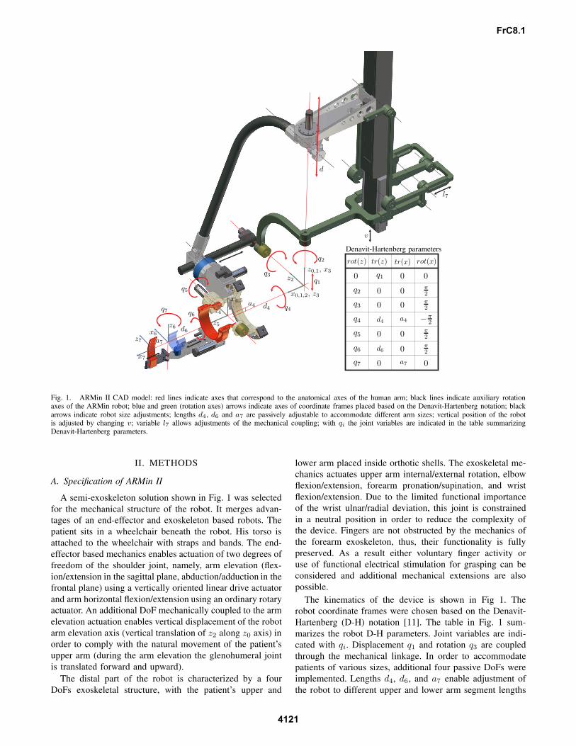
Fig. 1. ARMin II CAD model: red lines indicate axes that correspond to the anatomical axes of the human arm; black lines indicate auxiliary rotationaxes of the ARMin robot; blue and green (rotation axes) arrows indicate axes of coordinate frames placed based on the Denavit-Hartenberg notation; blackarrows indicate robot size adjustments; lengths d4, d6 and a7 are passively adjustable to accommodate different arm sizes; vertical position of the robotis adjusted by changing v; variable l7 allows adjustments of the mechanical coupling; with qi the joint variables are indicated in the table summarizingDenavit-Hartenberg parameters.
II. METHODS
A. Specification of ARMin II
A semi-exoskeleton solution shown in Fig. 1 was selectedfor the mechanical structure of the robot. It merges advan-tages of an end-effector and exoskeleton based robots. Thepatient sits in a wheelchair beneath the robot. His torso isattached to the wheelchair with straps and bands. The end-effector based mechanics enables actuation of two degrees offreedom of the shoulder joint, namely, arm elevation (flex-ion/extension in the sagittal plane, abduction/adduction in thefrontal plane) using a vertically oriented linear drive actuatorand arm horizontal flexion/extension using an ordinary rotaryactuator. An additional DoF mechanically coupled to the armelevation actuation enables vertical displacement of the robotarm elevation axis (vertical translation of z2 along z0 axis) inorder to comply with the natural movement of the patient’supper arm (during the arm elevation the glenohumeral jointis translated forward and upward).
The distal part of the robot is characterized by a fourDoFs exoskeletal structure, with the patient’s upper and
lower arm placed inside orthotic shells. The exoskeletal me-chanics actuates upper arm internal/external rotation, elbowflexion/extension, forearm pronation/supination, and wristflexion/extension. Due to the limited functional importanceof the wrist ulnar/radial deviation, this joint is constrainedin a neutral position in order to reduce the complexity ofthe device. Fingers are not obstructed by the mechanics ofthe forearm exoskeleton, thus, their functionality is fullypreserved. As a result either voluntary finger activity oruse of functional electrical stimulation for grasping can beconsidered and additional mechanical extensions are alsopossible.
The kinematics of the device is shown in Fig 1. Therobot coordinate frames were chosen based on the Denavit-Hartenberg (D-H) notation [11]. The table in Fig. 1 sum-marizes the robot D-H parameters. Joint variables are indi-cated with qi. Displacement q1 and rotation q3 are coupledthrough the mechanical linkage. In order to accommodatepatients of various sizes, additional four passive DoFs wereimplemented. Lengths d4, d6, and a7 enable adjustment ofthe robot to different upper and lower arm segment lengths
FrC8.1
4121

as well as hand sizes. Changing v by using an externalmechanism sets the vertical position of the robot for differentpatient heights. The additional variable l7 enables adjustmentof the mechanical coupling transmission ratio and is onlymeant for experimental purposes in order to find the bestrelation between joint variables q1 and q3.
The mechanism in Fig. 1 is positioned in a configura-tion where robot links are either parallel or perpendicular.However, it is clear that this can not be achieved for anysettings of parameters l7 and d4. This configuration waschosen to simplify the analysis of kinematics of mechanicalcoupling, thus, reducing the complexity of equations in thepaper by eliminating the need to include initial joint angles(deviations from 0◦ or 90◦). Therefore, equations in sectionII-B provide only a particular and not a global solution, butstill provide a rather general insight into the end-effectorbased mechanism kinematics. The calculation approach isthe same when searching for a global solution.
B. End-effector Based Mechanics
The first ARMin prototype was built with the shoulder axisof rotation fixed, which resulted in uncomfortable posturesfor the patient during extensive arm elevations (see [12]and [13] for details). In order to solve this issue severaloptions were considered. One option would be to use amotor in the rotation axis z2 (see Fig. 1) instead of usingthe linear drive for arm elevation. A smaller linear drivecould then be used for vertical displacement of the arm ele-vation axis. This solution was not adopted due to the safetyconsiderations – using the linear drive for arm elevationguarantees that the arm does not collapse quickly even inthe case of power failure. The second possibility would beto use the linear drive for the arm elevation and a smallerlinear drive for the vertical positioning of the arm elevationaxis. Again safety issues prevented the implementation ofsuch actuation – in case of a control failure the two drivesmight act in opposite directions and dislocate the patient’sshoulder. Therefore, a mechanical coupling between theshoulder elevation actuation and the shoulder elevation axiswas implemented. Such design guarantees safety, becausethe robot axes always match the human anatomical axes,regardless of the controller malfunction or power failure. Thedrawback of such coupling is the reduced range of motionof the arm elevation as will be shown later. However, thetherapy sessions with ARMin I proved that the resultingreduction of functional movements is not significant for thetherapy.
The kinematics of the end-effector based mechanics of therobot is shown in Fig. 2. As already mentioned the initialposition of the robot was selected such that all robot linksare either parallel or perpendicular (blue sketch). The redsketch indicates the displaced mechanism. The effect of themechanical coupling on the robot kinematics is analyzednext.
Based on the relations in Fig. 2 the following equations
q1
r0
d
l5
l6
l7
l4
l1
l2
l3
ϑ3
ϑ2
ϑ1
αβ
q3
x0,1,2
z0,1
z2
Fig. 2. Kinematic structure of the end-effector based mechanics with theemphasis on passive mechanical coupling between the arm elevation andthe vertical position of the center of rotation of the shoulder joint (positionof the glenohumeral joint); blue colored sketch indicates the robot in itsinitial position with all links either parallel or orthogonal; red colored sketchindicates the robot after the displacement from the initial position.
can be written
l4 sinϑ1 = d + l5(1 − cosϑ2)l5 sinϑ2 = l4(1 − cosϑ1).
(1)
Solving system (1) for ϑ1 gives the following result
ϑ1 =1
2l4 (l24 + (d + l5)2)arccos
(l4
(2l24 + d(d + 2l5)
)
+ (d + l5)√
4l24l25 − d2(d + 2l5)2
)⇐ d ≥ 0
ϑ1 =−1
2l4 (l24 + (d + l5)2)arccos
(l4
(2l24 + d(d + 2l5)
)
+ (d + l5)√
4l24l25 − d2(d + 2l5)2
)⇐ d < 0.
(2)
The vertical displacement of the arm elevation axis is then
q1 = l6 + l7 sin ϑ1 −√
l26 − l27(1 − cosϑ1)2. (3)
Next, arm elevation angle q3 will be determined. The angleis directly related to the angle α
α = arccos−l21 + l22 + l23 + (d + r0 − q1)2
2√
l22 + l23(d + r0 − q1). (4)
Since the mechanical coupling is not obligatory from therobot operation point of view, it can also be removed. Inthis case the arm elevation axis is constrained. Thus, verticaltranslation q1 is constant. Setting q1 = 0 simplifies (4) to
α = arccos−l21 + l22 + l23 + (d + r0)2
2√
l22 + l23(d + r0). (5)
Angle β is constant for each patient. The angle only dependson the constant value l2 and adjustable length l3, which
FrC8.1
4122
allows adjustment of the robot to different upper arm lengths(variations of D-H parameter d4 = l3 + const. in Fig. 1).Thus,
β = arctanl2l3
. (6)
Finally, q3 can be obtained as
q3 =π
2− (α + β). (7)
Due to the mechanical coupling the range of motion of armelevation is partially constrained. The mechanical couplingbecomes singular in two instances. In the first case links withlengths l4 and l5 become collinear. This occurs when the armis moved upward and the following condition is satisfied
l24 + (l5 + d)2 = (l4 + l5)2. (8)
From here it is possible to calculate the maximal displace-ment d as
dmax = −l5 +√
l5(l5 + 2l4) (9)
and q1max = 62 mm and q3max = 33◦ from (3) and (7),respectively.
On the other hand, the motion of the arm downward ishalted when links with lengths l6 and l7 become collinear.This occurs when the following condition is satisfied
l27 + (l6 − q1)2 = (l6 + l7)2. (10)
The minimal vertical displacement of the elevation axis isthen
q1min = l6 −√
l6(l6 + 2l7) (11)
resulting in q1min = −33 mm and q3min = −47◦. As alreadynoted, these limits are only valid for the configuration ofthe mechanical coupling as shown in Fig. 3 and need to berecalculated for different values of adjustable lengths l3 andl7.
The relations change if the mechanical coupling is re-moved. The movement of the arm elevation is halted in thiscase either when α = 0, thus,
α = 0 ⇒ q3max =π
2− β (12)
or when α = π resulting in
α = π ⇒ q3min = −π
2− β. (13)
Limits (12) and (13) are only theoretical. The range ofmotion of arm elevation is more constrained due to theshortness of the linear drive.
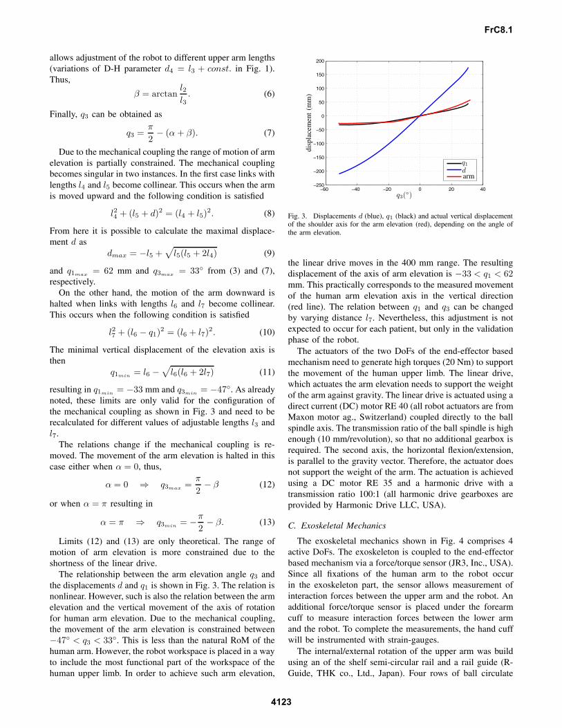
The relationship between the arm elevation angle q3 andthe displacements d and q1 is shown in Fig. 3. The relation isnonlinear. However, such is also the relation between the armelevation and the vertical movement of the axis of rotationfor human arm elevation. Due to the mechanical coupling,the movement of the arm elevation is constrained between−47◦ < q3 < 33◦. This is less than the natural RoM of thehuman arm. However, the robot workspace is placed in a wayto include the most functional part of the workspace of thehuman upper limb. In order to achieve such arm elevation,
−60 −40 −20 0 20 40−250
−200
−150
−100
−50
0
50
100
150
200
q3(◦)
disp
lace
men
t(m
m)
q1
darm
Fig. 3. Displacements d (blue), q1 (black) and actual vertical displacementof the shoulder axis for the arm elevation (red), depending on the angle ofthe arm elevation.
the linear drive moves in the 400 mm range. The resultingdisplacement of the axis of arm elevation is −33 < q1 < 62mm. This practically corresponds to the measured movementof the human arm elevation axis in the vertical direction(red line). The relation between q1 and q3 can be changedby varying distance l7. Nevertheless, this adjustment is notexpected to occur for each patient, but only in the validationphase of the robot.
The actuators of the two DoFs of the end-effector basedmechanism need to generate high torques (20 Nm) to supportthe movement of the human upper limb. The linear drive,which actuates the arm elevation needs to support the weightof the arm against gravity. The linear drive is actuated using adirect current (DC) motor RE 40 (all robot actuators are fromMaxon motor ag., Switzerland) coupled directly to the ballspindle axis. The transmission ratio of the ball spindle is highenough (10 mm/revolution), so that no additional gearbox isrequired. The second axis, the horizontal flexion/extension,is parallel to the gravity vector. Therefore, the actuator doesnot support the weight of the arm. The actuation is achievedusing a DC motor RE 35 and a harmonic drive with atransmission ratio 100:1 (all harmonic drive gearboxes areprovided by Harmonic Drive LLC, USA).
C. Exoskeletal Mechanics
The exoskeletal mechanics shown in Fig. 4 comprises 4active DoFs. The exoskeleton is coupled to the end-effectorbased mechanism via a force/torque sensor (JR3, Inc., USA).Since all fixations of the human arm to the robot occurin the exoskeleton part, the sensor allows measurement ofinteraction forces between the upper arm and the robot. Anadditional force/torque sensor is placed under the forearmcuff to measure interaction forces between the lower armand the robot. To complete the measurements, the hand cuffwill be instrumented with strain-gauges.
The internal/external rotation of the upper arm was buildusing an of the shelf semi-circular rail and a rail guide (R-Guide, THK co., Ltd., Japan). Four rows of ball circulate
FrC8.1
4123

between the rail and the rail guide bearing the load infour directions (radial, reverse-radial and the two lateraldirections). A DC motor RE 40 actuates the internal/externalrotation via a harmonic drive gearbox (transmission ratio100:1) and a tooth belt. A cuff made of a soft material isattached to the rail and provides the interface between therobot and the human upper arm. Due to the semi-circulardesign of the rail, the fixation of the arm to the exoskeletonis quick and easy.
The elbow joint axis is perpendicular to the upper arminternal/external rotation axis. The actuation of the elbowjoint is realized using a DC motor RE 35 and a harmonicdrive gearbox with a transmission ratio 100:1.
The forearm pronation/supination DoF is custom-designedusing a semicircular guide and a cart, which moves along theguide and on which the forearm support structure is attachedvia a linear guide. The linear guide provides a passive DoFto accommodate the exoskeleton to different forearm lengths.The actuation is achieved using a steel cable wrapped on theouter side of the guide and around the shaft of a motor RE30 attached to the cart (the steel cable is at the same timewrapped around the shaft of a multi-turn potentiometer). Thecart motion is constrained to the semicircular guide by 16ball bearings as shown on the left side in Fig. 4. The ballbearings are placed such to bear forces in four directions.The only movement allowed is along the semicircular guide.The human forearm is coupled to the exoskeleton through aforearm cuff attached to a force/torque sensor and coveredin soft material.
The wrist flexion/extension DoF is implemented using aDC motor RE 25 attached to a high-efficiency ball spindle(Abssac Ltd., UK), which is further connected to a leversystem used to transform the linear motion into the rotationaround the wrist flexion/extension joint. The hand cuff at-taches to the outer side of the hand using a velcro band. Itsposition is adjustable to accommodate different hand sizes.The movement of the fingers is not obstructed. Therefore,they can be considered for training of ADLs.
All robot axes are backdrivable. However, the frictionin most of the joints is considerable due to the use ofthe harmonic drive gearboxes or ball spindles. The axesare instrumented with high resolution encoders and linearor angular position transducers providing the redundantposition information as well as the absolute position ref-erence. The robot bacdrivability in combination with theuse of force/torque sensors enables the implementation ofimpedance or admittance based patient cooperative controlstrategies.
III. RESULTS
The ARMin II prototype with a subject being exercised isshown in Fig. 5. A 3D graphical display using a large screenand two overhead projectors as well as a sound system with6 speakers (not shown in the figure) were added to generatevirtual environments for arm rehabilitation. Haptic feedbackis provided by the robot. The robot is currently being evalu-ated with healthy volunteers in order to optimize settings of
force/torque sensor
force/torque sensorharmonic drive
harmonic drive
motor
motor
motor
motor
linear guidesemi-circular guide
rail guide
semi-circular rail
forearm cuff
hand cuff
wrist flex./ext.
elbow flex./ext.
forearm pron./sup.
int./ext. rot.
potentiometer
potentiometer
potentiometer
cart
tooth belt
steel cable
ball spindle
tooth belt pulleys box
Fig. 4. Exoskeletal mechanics enabling actuation of shoulder inter-nal/external rotation, elbow flexion/extension, forearm pronation/suppinationand wrist flexion/extension; the exoskeletal part is coupled to the end-effector based mechanics through a force/torque sensor.
Fig. 5. Subject sitting in a wheelchair is coupled to the ARMin II robot.A physiotherapist sitting near by is selecting the rehabilitation procedure.
the mechanical structure and control system. The preliminaryresults are encouraging. Especially the comfort when usingthe robot has been significantly increased compared to thefirst ARMin prototype, due to the vertical movement of theshoulder joint center of rotation. At the same time the robotallows more complex arm movements due to two additionalDoFs. Fingers movement is not obstructed by the robot.
FrC8.1
4124
Therefore, use of functional electrical stimulation or devicessuch as Rutgers Master [14] can be considered.
A. Comparison of Human and Robot RoM
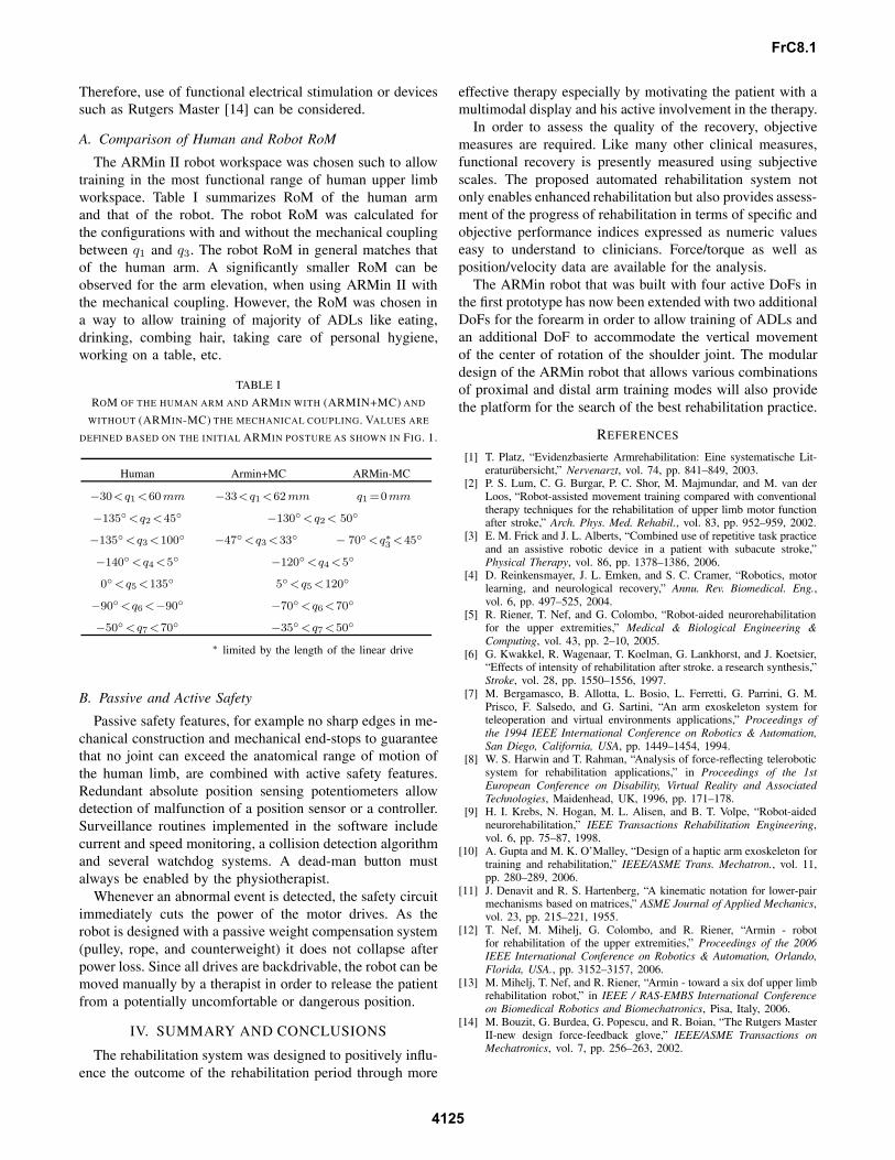
The ARMin II robot workspace was chosen such to allowtraining in the most functional range of human upper limbworkspace. Table I summarizes RoM of the human armand that of the robot. The robot RoM was calculated forthe configurations with and without the mechanical couplingbetween q1 and q3. The robot RoM in general matches thatof the human arm. A significantly smaller RoM can beobserved for the arm elevation, when using ARMin II withthe mechanical coupling. However, the RoM was chosen ina way to allow training of majority of ADLs like eating,drinking, combing hair, taking care of personal hygiene,working on a table, etc.
TABLE I
ROM OF THE HUMAN ARM AND ARMIN WITH (ARMIN+MC) AND
WITHOUT (ARMIN-MC) THE MECHANICAL COUPLING. VALUES ARE
DEFINED BASED ON THE INITIAL ARMIN POSTURE AS SHOWN IN FIG. 1.
Human Armin+MC ARMin-MC
−30<q1 <60 mm −33<q1 <62 mm q1 =0mm
−135◦ <q2 <45◦ −130◦ <q2< 50◦
−135◦ <q3<100◦ −47◦ <q3 <33◦ − 70◦ <q∗3 <45◦
−140◦ <q4 <5◦ −120◦ <q4 <5◦
0◦ <q5 <135◦ 5◦ <q5 <120◦
−90◦ <q6 <−90◦ −70◦ <q6<70◦
−50◦ <q7<70◦ −35◦ <q7<50◦
∗ limited by the length of the linear drive
B. Passive and Active Safety
Passive safety features, for example no sharp edges in me-chanical construction and mechanical end-stops to guaranteethat no joint can exceed the anatomical range of motion ofthe human limb, are combined with active safety features.Redundant absolute position sensing potentiometers allowdetection of malfunction of a position sensor or a controller.Surveillance routines implemented in the software includecurrent and speed monitoring, a collision detection algorithmand several watchdog systems. A dead-man button mustalways be enabled by the physiotherapist.
Whenever an abnormal event is detected, the safety circuitimmediately cuts the power of the motor drives. As therobot is designed with a passive weight compensation system(pulley, rope, and counterweight) it does not collapse afterpower loss. Since all drives are backdrivable, the robot can bemoved manually by a therapist in order to release the patientfrom a potentially uncomfortable or dangerous position.
IV. SUMMARY AND CONCLUSIONS
The rehabilitation system was designed to positively influ-ence the outcome of the rehabilitation period through more
effective therapy especially by motivating the patient with amultimodal display and his active involvement in the therapy.
In order to assess the quality of the recovery, objectivemeasures are required. Like many other clinical measures,functional recovery is presently measured using subjectivescales. The proposed automated rehabilitation system notonly enables enhanced rehabilitation but also provides assess-ment of the progress of rehabilitation in terms of specific andobjective performance indices expressed as numeric valueseasy to understand to clinicians. Force/torque as well asposition/velocity data are available for the analysis.
The ARMin robot that was built with four active DoFs inthe first prototype has now been extended with two additionalDoFs for the forearm in order to allow training of ADLs andan additional DoF to accommodate the vertical movementof the center of rotation of the shoulder joint. The modulardesign of the ARMin robot that allows various combinationsof proximal and distal arm training modes will also providethe platform for the search of the best rehabilitation practice.
REFERENCES
[1] T. Platz, “Evidenzbasierte Armrehabilitation: Eine systematische Lit-eraturubersicht,” Nervenarzt, vol. 74, pp. 841–849, 2003.
[2] P. S. Lum, C. G. Burgar, P. C. Shor, M. Majmundar, and M. van derLoos, “Robot-assisted movement training compared with conventionaltherapy techniques for the rehabilitation of upper limb motor functionafter stroke,” Arch. Phys. Med. Rehabil., vol. 83, pp. 952–959, 2002.
[3] E. M. Frick and J. L. Alberts, “Combined use of repetitive task practiceand an assistive robotic device in a patient with subacute stroke,”Physical Therapy, vol. 86, pp. 1378–1386, 2006.
[4] D. Reinkensmayer, J. L. Emken, and S. C. Cramer, “Robotics, motorlearning, and neurological recovery,” Annu. Rev. Biomedical. Eng.,vol. 6, pp. 497–525, 2004.
[5] R. Riener, T. Nef, and G. Colombo, “Robot-aided neurorehabilitationfor the upper extremities,” Medical & Biological Engineering &Computing, vol. 43, pp. 2–10, 2005.
[6] G. Kwakkel, R. Wagenaar, T. Koelman, G. Lankhorst, and J. Koetsier,“Effects of intensity of rehabilitation after stroke. a research synthesis,”Stroke, vol. 28, pp. 1550–1556, 1997.
[7] M. Bergamasco, B. Allotta, L. Bosio, L. Ferretti, G. Parrini, G. M.Prisco, F. Salsedo, and G. Sartini, “An arm exoskeleton system forteleoperation and virtual environments applications,” Proceedings ofthe 1994 IEEE International Conference on Robotics & Automation,San Diego, California, USA, pp. 1449–1454, 1994.
[8] W. S. Harwin and T. Rahman, “Analysis of force-reflecting teleroboticsystem for rehabilitation applications,” in Proceedings of the 1stEuropean Conference on Disability, Virtual Reality and AssociatedTechnologies, Maidenhead, UK, 1996, pp. 171–178.
[9] H. I. Krebs, N. Hogan, M. L. Alisen, and B. T. Volpe, “Robot-aidedneurorehabilitation,” IEEE Transactions Rehabilitation Engineering,vol. 6, pp. 75–87, 1998.
[10] A. Gupta and M. K. O’Malley, “Design of a haptic arm exoskeleton fortraining and rehabilitation,” IEEE/ASME Trans. Mechatron., vol. 11,pp. 280–289, 2006.
[11] J. Denavit and R. S. Hartenberg, “A kinematic notation for lower-pairmechanisms based on matrices,” ASME Journal of Applied Mechanics,vol. 23, pp. 215–221, 1955.
[12] T. Nef, M. Mihelj, G. Colombo, and R. Riener, “Armin - robotfor rehabilitation of the upper extremities,” Proceedings of the 2006IEEE International Conference on Robotics & Automation, Orlando,Florida, USA., pp. 3152–3157, 2006.
[13] M. Mihelj, T. Nef, and R. Riener, “Armin - toward a six dof upper limbrehabilitation robot,” in IEEE / RAS-EMBS International Conferenceon Biomedical Robotics and Biomechatronics, Pisa, Italy, 2006.
[14] M. Bouzit, G. Burdea, G. Popescu, and R. Boian, “The Rutgers MasterII-new design force-feedback glove,” IEEE/ASME Transactions onMechatronics, vol. 7, pp. 256–263, 2002.
FrC8.1
4125