Armed services I echnical iotormation Itgeoc)AII-109 1 On Elastic Plastic Deformation in Beams under...
27
Armed services I echnical iotormation Itgeoc) Because of our limited supply, you are requested to return this copy WHEN IT HAS SERVED YOUR PURPOSE so that it may be madw available to other requesters. Your cooperation will be appreciated. NOTICE: WHEN GOVERNMENT OR OTHER DRAWIDM, SPECIFICATIONS OR OTHER DATA XIE1TBD FOR ANY PURPOSE OTHER THAN IN CONNECTION WITH A DEFINiTELY RELATED GOVERNMENT PROCUREMENT OPERATION, THE U. S. GOVERNMENT THEREBY INCURS NO RESPONSIBILITY, NOR ANY OBLIGATION WHATSOEVER; AND THE FACT THAT THE GOVERNMENT MAY HAVE FORMULATED, FURNISHED, OR IN ANY WAY SUPPLIED THE SAID DRAWINGS, SPECIFICATIONS, OR OTHER DATA IS NOT TO BE REGARDED BY IMPLICATION OR OTHERWISE AS IN ANY MANNER LICENSING THE HOLDER OR ANY OTHER PERSON OR CORPORATION, OR CONVEYING ANY RIGHTS OR PERMSSION TO MANUFACTURE, USE OR SELL ANY PATENTED INVENTION THAT-MAY IN ANY WAY BE RELATED THERETO. Rproducel by DOCUMENT SERVICE CENTER KNOTT BUILDING, DAYTON, 2,-.OHIO
Transcript of Armed services I echnical iotormation Itgeoc)AII-109 1 On Elastic Plastic Deformation in Beams under...

Armed services I echnical iotormation Itgeoc)Because of our limited supply, you are requested to return this copy WHEN IT HAS SERVEDYOUR PURPOSE so that it may be madw available to other requesters. Your cooperationwill be appreciated.
NOTICE: WHEN GOVERNMENT OR OTHER DRAWIDM, SPECIFICATIONS OR OTHER DATAXIE1TBD FOR ANY PURPOSE OTHER THAN IN CONNECTION WITH A DEFINiTELY RELATEDGOVERNMENT PROCUREMENT OPERATION, THE U. S. GOVERNMENT THEREBY INCURSNO RESPONSIBILITY, NOR ANY OBLIGATION WHATSOEVER; AND THE FACT THAT THEGOVERNMENT MAY HAVE FORMULATED, FURNISHED, OR IN ANY WAY SUPPLIED THESAID DRAWINGS, SPECIFICATIONS, OR OTHER DATA IS NOT TO BE REGARDED BYIMPLICATION OR OTHERWISE AS IN ANY MANNER LICENSING THE HOLDER OR ANY OTHERPERSON OR CORPORATION, OR CONVEYING ANY RIGHTS OR PERMSSION TO MANUFACTURE,USE OR SELL ANY PATENTED INVENTION THAT-MAY IN ANY WAY BE RELATED THERETO.
Rproducel byDOCUMENT SERVICE CENTER
KNOTT BUILDING, DAYTON, 2,-.OHIO

OFFICE OF NAVAL RESEARCH
3 Contract N7onr-35801
6Aw NR-041-032
Technical Report No. 109
ON ELASTIC PLASTIC DEFORMATION
IN BEAMS UNDER DYNAMIC LOADING
by
J. A. Seller
DIVISION OF APPLIED MATHEMATICS
BROWN UNIVERSITY
PROVIDENCE, R. I.
April, 1954
All-109

AII-109 1
On Elastic Plastic Deformation
in Beams under Dynamic Loading1
by J. A. Seiler2
Abst at: This paper gives an elastic-plastic analysis of a
simply supported uniform beam subjected to a uniform pressure
applied as a pulse of rectangular shape. Plastic flow is taken
account of only at a plastic hinge at the mid-section of the
beam. The resulting permanent deformations are compared with
those predicted by a "rigid-plastic" type of analysis in which
elastic deformations are neglected. Because of the failure of
the elastic-plastic analysis to consider the plastic deformations
at cross-sections other than the middle section t the two solu-
tions do not agree even at large load values. The elastic-
plastic results are in better agreement with an incorrect rigid-
plastic treatment in which plastic hinge action is assumed to
occur only at the mid-point.
I. Introduction
There has recently been considerable study of the plastic
deformations of beams and frames under dynamic loading, on the
basis of the "plastic-rigid" hypothesis [1, 2, 3, 4, 5, 613 .
1. The results in this paper were obtained in the course ofresearch conducted under Contract N7onr-35801 between BrownUniversity and the Office of Naval Research.
2. Research Assistant, Division of Applied Mathematics, BrownUniversity.
3. Numbers in square brackets refer to the bibliography at theend of the paper.
A ,

All-l09 2
According to this hypothesis there is no curvature change at a
given section of a beam unless a bending moment of a certain
magnitude is maintained at that section. Where this moment
(called the limit or fully plastic moment) is maintained, "plas-
tic hinge" action can occur as long as the bending moment main-
tains its limit value. The neglect of elastic deformations is
permissible when the loads are of such a magnitude as to produce
plastic strains large in comparison with any possible elastic
strains.
In order to determine the range of loading in which the
neglect of elastic deformations is permissible, it is desirable
to make analytical studies in which elastic as well as plastic
strains are considered. One study of this type has been carried
out by Bleich and Salvadori [7) for a problem of impulsive
motion (specified initial velocity) of a uniform beam with free
ends. The present paper treats the elastic and plastic motions
of a simply supported beam subjected to a specified dynamic
load, namely a uniformly distributed pressure applied as a
pulse of rectangular shape. The analysis used here is essen-
tially the same as that of [7]. The initial elastic motion is
represented as a series of eigenfunctions. The initial wholly
elastic phase terminates when the bending moment at any section
reaches the limit moment magnitude* Thereafter at such a sec-
tion the moment is held constant at the limit moment magnitude
and the previous condition of slope continuity is relaxed* Thus
"plastic hinge" action occurs at such a section as long as the
relative angular velocities across the section are in the same
4Ali

All-109 3'I
sense as the moment at the hinge. The subsequent elastic motions
of the segments separated by the hinge section are then repre-
sented by a new series of eigenfunctions corresponding to the new
boundary conditions, with amplitudes chosen so that the elastic-
plastic solution matches the wholly elastic one,
The plastic-rigid solutions of beam problems show that
there are in general not only plastic hinges at fixed cross-
sections, but also either travelling plastic hinges or finite
plastic regions of changing size. Although the solution of
elastic-plastic problems by synthesizing eigenfunctions can
clearly be carried out when one or more fixed plastic hinges are
present) this method is not applicable when moving hinges or
elastic-plastic interfaces occur. Thus in [7] it is assumed
in the numerical example treated that plastic hinge action occurs
only at the center of the beam. This is certainly correct for
low enough initial velocities and incorrect for very high ini-
tial velocitieso Unfortunately, since the plastic-rigid type
of analysis requires the initial velocities to be high in order
for the analysis to be appropriate, it is evident that the
validity of the plastic-rigid analysis cannot be assessed by
comparison with the results of a "single-hinge" type of elastic-
plastic analysis. In [7] Bleich and Salvadori compared the
deformations of their elastic-plastic solution with those of a
fictitious rigid-plastic solution in which a plastic hinge was
assumed to occur only at the center, the two halves of the beam
moving as rigid bars. Their elastic-plastic results were found
to coincide at high initial velocities with those of this

All-109
"single-hinge" rigid-plastic solution. This is clearly to be
expected since both solutions would be correct for a bar suffi-
ciently strengthened at sections other than the middle section.
The simplest case to which the above method.applies is
the one degree of freedom system, illustrated by a mass on a
spring. This problem has been thoroughly worked out by Brooks
and Newmark [8], and will be described here to illustrate both
the general method of elastic-plastic analysis and the expected
relation between the results of this analysis and those of the
simpler rigid-plarstic analysis.
Consider the system shown in Fig. 1. The spri-ng force-
displacement curvet according to the above method, is taken as
shown in Fig. 2, and for simplicity, we consider a rectAngular
pulse shape as shown in Fig. 3.
If x is the displacement of the mass, p is the load
intensity, and k is the spring constant, then the equation of
motion of the mass m, as the load is first applied is
m = p -kx (1)
subject to • x(O) = x()= Or 2
'where the dot denotes time differentiation. The system (1),
(2) has the solution
x = (1- cos t). (3)
The system reaches its maximum elastic response when.
X = Xy, the yield displacement which occurs at time t = ty
e

All-109
given by
t arc-cos (a)
where we define the dimensionless parameter L to be
p
At time t = ty we have
x yx= Xy
/ (5)
which are used as initial conditions for the new equation of
motion of the mass in the plastic range, i.e.
mx= p - kxy. (6)
Equation (6), together with initial conditions (5) has solutionp-kxy 2 2kt-t) y 7P Ym (t - ty) + 7( y 7
At time T the load ends, at which time the velocity and dis-
placement of the mass are:2 - Ykty)2 P /k 2S m ( ; t+ ty ) + x (8)
p - - .
m Y 1V
The equation of motion of the mass now becomes
mx = - y (9)
subject to (8) as initial conditions. The system (8), (9) has
solution

All-109 6
'Ix -t 2- . + P s(pm - ky ty2
2mm (C" - t- t) + Xy.L~~~t
pkx t : 2 + p ('t ) +
(10)
To find the maximum response of the system, we set x = 0
and solve for t, insert this back in (10) and obtain an expres-
sion for the final maximum response XF:
kx y- 2 (Y) t 2 I2 l txF= m 2 +)
+ (2 LL + 1)] (11)
We now define a dimensionless pulse time C = 1 T
in terms of which (11) gives the dimensionless maximum displace-
ment XF asmx F 2(XF)EP.= " F =.-M, _ [i -[ arc-cos
(X)EP kXy' 2
+ 2- [- arc-cos 1) -) + 2 + 1 (12)
where the arc-cos function is restricted, of course, to its
principle value.
It is evident that for low enough load intensity and/or
short enough pulse time, we might not have yielding, or that
yielding might occur after the load is removed. The analysis in
this case is much the same and will not be presented here. The
resulting dimensionless deformation is
(XF)E.p [2(1 - cos C) + J] (13)kx,,

'I All-109 7
here is restricted to have a small enough value so that yield-
ing will not occur during the force pulse.
Consider now the plastic-rigid problemg i.e., with a
spring-force displacement curve as shown in Fig. 4. In this
case a similar analysis yields the following expression for the
dimensionless maximum displacement:
(XF)Rp = 111 (L - 1). (14)
Figure 5 shows curves of (XF)E.P. vs load intensity i
for various C, and also the curve of (XF)R.p. vs. .
The criterion for the validity of a plastic-rigid analy-
sis of this problem, following that put forth in [1], is that
we must have 2-y(XF)Rop. >> I kxy2
Relation (15) states that the plastic work (i.e., yield force
multiplied by the plastic deformation) must be much greater than
the maximum elastic strain energy that can be stored in the
spring. Relation (15) can also be written in the following form:
WP = 2- (1 - ) >> l, (16)
where Wp and WE are, respectively, the plastic work and the
maximum elastic strain energy.
It is seen from Figs. 6(a), (b), (c) that the validity
of the rigid-plastic analysis of this problem cannot be ascer-
tained from the magnitude of the energy ratio Wp/WE alone. The
validity must also depend upon an inequality being satisfied by
a

Al1-109 8
one of the parameters , 4. In other terms, one cannot make a
positive statement that Wp/WE being greater than some number
implies that the error involved in the rigid-plastic hypothesis
is less than some preassigned value. The statement that can be
made is that given a fixed ratio of pulse time to period, a
value of WP/WE can be found so that the error is less than any
preassigned amount.
Figure (6) shows plots of percent error vs. p, for various
WP/WE values. Figure 6 may be interpreted as follows. If, say,
Wp/WE = 10 and jL = 13, then the error involved in the plastic-
rigid assumption will always be less than 15% provided the pulse
time is larger than the value obtained from (16) namely
= .253, which implies a pulse time of .01+0 periods.
II. Elastic Response of Beams
We now proceed to the discussion of a simply supported
beam of mass m per unit length, and length t as indicated in
Fig. 7, acted on by a uniform load of intensity p per unit
length. We again consider only the rectangular force pulse
shape as in Fig. 3. The equation for the displacement y (x,t)
of the beam is, (neglecting the effects of shear and rotary
inertia)(EIyxx)xx + mytt = p (17)
The initial and boundary conditions are
y(x,O) = yt(x,O) = 0
y(Ot) = Yx(Ot) 0 (18)
y(.,t) = Yxx(-tt) = 0.
pr'-

All-109 9
The eigenfunctions of the homogeneous system are
Tn(X) = sin MA,
and we assume a solution in the form
00y(xpt) = E Pn(x)qn(t), (19)
n=1
where each generalized coordinate qn(t) must satisfy the
Lagrangian equations
d T () + .= Qn, (20)Nq 8%
and where
T = (Y dx ' (21)
V = (Yx)2 dx, (22)
jo
Qn= P(xt)Tn(x)dx = P I sin MA dx. (23)
Upon substitution of (21), (22), (23) into (20) we find
qn(t) = -- (1 - cos X2 t), (24)nmitX4
where
n 1, 3, 5 see
X I+ R k
Hence our solution for y(xt) becomes
y(xlt) =i ZOD sin cs2 2(yix , x5EI n=l,3( O t). (2)

All-109 10
This solution is valid until the bending moment reaches
its capacity value Mo at the center of the beam. In order to
find the time to at which this occurs we set the bending moment
M(xjt o ) = EIYXX(Xlt o0) equal to Mo at x =t/2. We obtain
4pt?, 0 "-i n 2 n2to
M nl,3 n3,E (i - cos 0)" (26)
We now define dimensionless load and time parameters 1.
and q to be 2 2
No 7 aitt
Then (26) becomesn-l
3 D2 (3-1E = Q 3 cos n 2io (27)3 ~ n=113 n
where qo = x2to/ke2
The right-hand side of Eq. (27) is plotted vs. no0 and
for each p value the intersection of left- and right-hand sides
gives the time for the moment to reach Mo at x = /2. Figure 8
shows a plot of q versus the load parameter . At time 9 = qo
the velocity and displacement of all points of the beam are
given by:
y(xjt0 ) = E sin sin r f (i- cos n 2 o) (28)
2 0
Y(xtt o ) E 2
y(x 3 -sin sin n no. (29)7 3Efk n=1,3 n

All-109 11
Now a new problem must be solved; we have a beam of
length t/2, simply supported at one end, with zero shear and
constant moment Mo at the other end, and with the above displace-
ment and velocity as initial conditions (Fig, 9)e
This problem as it stands does not lend itself to solu-
tion by a sum of eigenfunctions, since the boundary conditions
are non-homogeneous. However, the problem can be separated into
two parts. We seek a function y(xjt'), where tO 5 t - to, such
that 2p 1
kt~t EI
y(Ot') y(0,tt) = 0 (30)
= y (,t 0Yxx( t ) xxx 22V
to which we add a particular solution satisfying the non-homo-
geneous boundary conditions of zero shear and constant moment
at the free end of the beam. The desired solution is0o b 2 t b 2tIn n
y(xt') (A + Bt)x + Z fn()[An sin = + Bn cos nn=l ktkr
+ n
EIb (sinh n + sin - 2
3 2 (31)
where A, B, A En are constants to be determined from the
*i initial conditions, W(X) are the eigenfunctions of the half
4 V

A1l-109 12
beam, and bn are the eigen values:
sin sinh - x + sinh sinbx
bn bntanh -=tan , or
b R (4n + 1).
Proceeding in the usual way for determining the coeffi-
cients, we find: -1
OD - ) 2 2 & + ll7)MoZA E (l -( cos ni) + 11) 0 t
R7EI n=1,3 n- 0 1680 El
96pt, 0 2B E z2~. sinn5 EI n=113 0M-b ()T2
16 /7 pe(-)n cosh O 1) sin m 2
3 Eibn(sih 2 n _ sin2 &) m=,3 m(m 7t bnj)
b rm-i1+ b 12
16 2 ptb n(-l)n cosh 0o (-1) - (1- cos m20)
B 3E1(sinh2 n Sin2 b)
2 b b4M2 sin n cosh n(I, + 8)
+ ... ..0_ _ . .. ._ ._ _ 7-
E 3 2 b 2 b Lbn (s(ih sin n)
bn bjg(sinh -sin n) 4
4pb 2 - n

All-109 13
This solution applies until
t ~
at which time the load is removed. For convenience we define
a dimensionless quantity C by A/kt?; physically is 2n
times the ratio of pulse duration to fundamental period, Thenat time q = C the velocity and displacement of all points of the
beam are given byk2(. - q) kt2(C n) kz2(-.no)
y(xl 2 (A + B - ) x + *(x, 2 )7E 7ET -
OD b 2(C - no) bn2 (- 10)+ Z n(X)[An sin n + Bn cosn=l 7 2 7 E2
+ b bn (32)
EIbn (sinh n+ sin
yt,(x no) Bx + ; k2 -(C )
I27
+ CO ( X)b n2 [no b n( _ no) b n2(C - no)E 2 2 [A sin 2 - s3n
n=l k2 s k2
where *(xlt') is the particular solution of (30).
The system (30) must now be solved with p = 0, subject
to the initial conditions (32) and (33). With p = 0 (30) has
the solution00 b n2t"Ibn2I
y(xt") = (A + B't")x + Z Tn(x)(A sin + o b 2 t"n=l 2
Mo 2
042~"
All-109 14
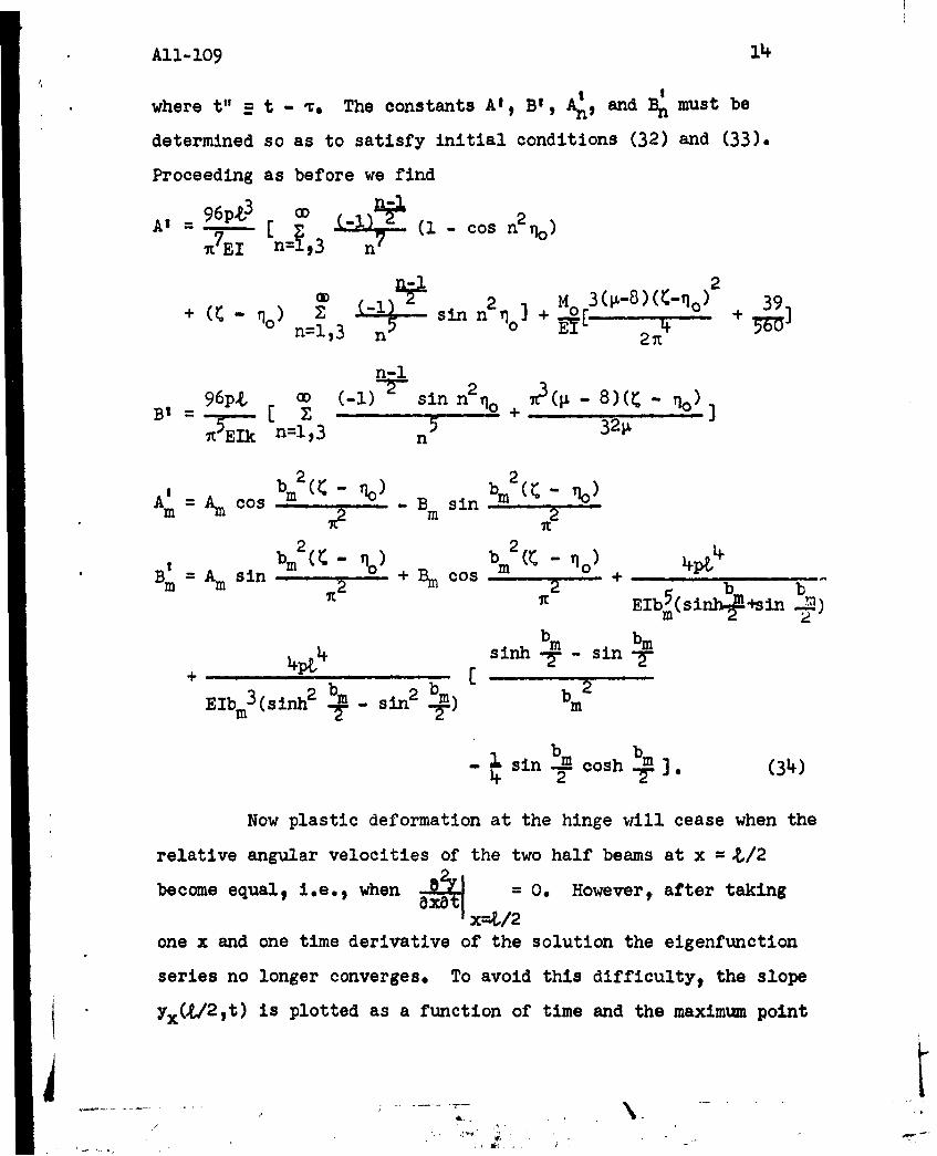
where t" = t - T. The constants Aft B', A 1 and Bn must be
determined so as to satisfy initial conditions (32) and (33).
Proceeding as before we find
A' = 96pL 3 -I (I-con2qo)
JTEI n=l,3 J)2
+ (C- q) Z -1) sin n q + Mo 3(j-S+~% 390 n=1,3 n5 0 EY 2nt
n-i96p.t a (-1) = sin n0 + 7t(O - 8)(C - qo)
BI= I z 5 3211,KEkn=1,3 n
bm2 (- ob 2 ( 0Am = Am cos .... . Bm sin
Ibin2 ( bin2 ( - o 0) 4pt
44 sinh bm- sin b
2b)bm2 bED3(sinh bm - sin2 bm
- sin acosh -b2 m (34)E~m3 1i+h 2-m
Now plastic deformation at the hinge will cease when the
relative angular velocities of the two half beams at x =.L/2
become equal, i.e., when t = 0. Howevero after taking- -x-t /2
one x and one time derivative of the solution the eigenfunction
series no longer converges. To avoid this difficulty, the slope
yx(/ 2 ,t) is plotted as a function of time and the maximum point
4 - --
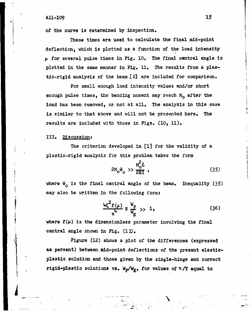
All-109 15
of the curve is determined by inspection.
These times are used to calculate the final mid-point
deflections which is plotted as a function of the load intensity
1L for several pulse times in Fig. 10. The final central angle is
plotted in the same manner in Fig. 11. The results from a plas-
tic-rigid analysis of the beam [2) are included for comparison.
For small enough load intensity values and/or short
enough pulse times, the bending moment may reach Mo after the
load has been removed, or not at all. The analysis in this case
is similar to that above and will not be presented here. The
results are included with those in Figs. (10, 11).
III. Discussion:
The criterion developed in [1] for the validity of a
plastic-rigid analysis for this problem takes the form
2Mo0 >> - (35'
where o is the final central angle of the beam. Inequality (35)
may also be written in the following forms
Wi. f( ) =wp>> (36)
7C E
where f(p) is the dimensionless parameter involving the final
central angle shown in Fig. (11).
Figure (12) shows a plot of the differences (expressed
as percent) between mid-point deflections of the present elastic-
plastic solution and those given by the single-hinge and correct
rigid-plastic solutions vs. Wp/WE, for values of /T equal to
4i.. .... . ..... ... J" - -- A .

All-109 16
1/2 and 2. T is the fundamental period of vibration of the beam*
It is seen that for Wp/WE becoming large, the single-
hinge rigid-plastic solution differs very much from the correct
rigid-plastic results and is presumably wrong since violations
of the plasticity condition would occur at sections other than
the mid-section. The approach to agreement as WP/WE becomes
large of the present elastic-plastic solution with the single-
hinge rigid-plastic solution is to be expected on the basis of
the energy hypothesis for the validity of a rigid-plastic analy-
sis: both solutions are correct (for very large Wp/WE ) for a
beam strengthened so that plastic flow takes place only at the
mid-section where the bending moment is equal to Mo . The agree-
ment at large WP/WE values between the single-hinge rigid-plastic
solution and the present elastic-plastic solution can thus be
taken as an indication that the elastic-plastic results are
incorrect in the range of large Wp/WE. However, the elastic-
plastic analysis gives accurate results for fairly low load
intensities, where the deformation is mainly elastic and plastic
deformation occurs only at a single hinge at the center of the
beam.

All-109 17
Bibllogra h=
1, "Large Plastic Deformations of Beams under TransverseImpact", by E. H. Lee and P. S. Symonds, Journal ofAppi. Mech. Vol. 19, No. 3, pp. 308-314, Sept. 1952o
2, "Large Plastic Deformations of Beams under Blast TypeLoading" by P. S. Symonds, Tech. Rept. All-99, BrownUniversity, 1953; to appear in Proc, Second U. S.National Congress of Applied Mechanics.
3e "Dynamic Load Characteristics in Plastic Bending of Beams"$by P. S. Symonds, Journal of Applied Mechanicsq Dec.1953.
4. "A Note on Large Plastic Deformations of' Beams under Trans-verse Impact", by T. H. H. Pian M.I.T. Aero-Elasticand Structures Res. Lab. Report for ONR contractNSori-07833, May 1952.(Paper presented at Eighth Inter-national Congress of Theoretical and Applied Mechanics,August. 20-28 1952.)
5, "On the Development of Plastic Hinges in Rigid-Plastic Beams";by M. G. Salvadori and F. DiMaggiol Quart, Applied Math.XI, pp. 223-230, 1953.
6. "Plastic Deformation in Beams under Symmetric Dynamic Loads",by J. A. Seiler and P. S. Symonds, Tech. Report Bll-139 Brown University, 1953; to appear in Jour. AppliedPhysics.
7. "Impulsive Motion of Elasto-Plastic Beams" by H. H. Bleichand M. G. Salvadori, Proceedings American Society ofCivil Engineers, Separate No. 287, Sept. 1953.
8. "Response of Simple Structures to Dynamic Loads" by N. B.Brooks and N. M. Newmark, Tech. Report to OR contractN6ori-071(06), Task Order VI, Project NR-06+-1839University of Illinois, 1953.
4

All -109I
4-u
*0U0
00V0 0 p
CLL
chS
0..4-LG

Elastic-Plastic
for 'r 079 5 Peri'ods
400O
*nx Rigid -Plasticy
300
Note: Elastic-Plastic200 Curves for x1> .0795
Periods Lie. Betweenthe Two Curves
100-
00 5 .10. 15 190 25 30 3
Fig. 5.. Final Deformation vs. Load-Moss Spring SysteM

40-
.
E P-R.PFig. 6(a). Plot of %/ Oitference ,t.P x 100)
vs -f for VariousWE
45.40
35-
W30
~1.0
10
F ig. 6(b). Plot of %/~ Dif ference vs.M forVorious WE

AH-lOS 21
50
40-
&3O-
.4)
10- 25
100
~02 46 8 1012 14 161820
EP-RPFig 6(c). 0/ Difference (-- x 100) VS. 1
For Various W2-~ valuesWE
p
P g. 7.

IAll -109 22
1.50
1.25
1.00
.75-
.50
.25
I . I p
0 10 20 30. 40 50 60 70
Fig. 8. Plot of vs. )
p
2
* Fig. 9.

'23
4
380
360
340 /320-
300- Elastic- Plastic:280- t:4 F'Priod
260-
240
IS80 Elastic-Plastic1: 2 Periods
160140. Single Hinge
Rigid -Plastic120.
100 Correct Rigid-80- Plastic
SO-/40-
20
0 10 20 30 40 50 60 70-
* Fig. 10. Final Mid.-point Deflection vs.

AllO 109
800-
Elastic-PlasticT3 Period
m e-500. Single Hfnge
Rigid- Plastic400
Elastic-Plsticwo - 'r x2 Periods
200Correct, R ig id
Plastic10oo
0 10 20 30 p 40 50 60 70.
Fig. 11. Final Central Angle vs. p

Ait -iog
25
Io 0
UJ V)
IICY
IV
CY-
400cu,