Didier Coulomb - IIR - SOSTENIBILITA’ DEL TRASPORTO REFRIGERATO SU STRADA

ARMADIO REFRIGERATO REFRIGERATED CABINET
BASICQUICK
FISH
Manuale d’uso e manutenzioneUse and maintenance manual
Rev.7-6
1
ITALIANO
Grazie per aver scelto questo prodotto.
Leggere attentamente le avvertenze contenute nel presente manuale in quanto forniscono importanti indicazioni riguardanti la sicurezza, d’uso e di manutenzione.Conservare con cura questo manuale per ogni ulteriore consultazione dei vari operatori.
In alcune parti del manuale è presente il simbolo indicante una avvertenza importante da rispettare ai fini della sicurezza.
CAPITOLO 1 CARATTERISTICHE LIMITE DI FUNZIONAMENTO
L’armadio frigorifero è stato progettato e realizzato per poter funzionare in condizioni ottimali in ambienti con temperature fino a +10°C e i +43°C ( BASIC ), +10°C e i +38°C ( QUICK - FISH )con adeguato ricircolo d’aria. In luoghi con caratteristiche diverse da quelle previste non sarà possibile garantire le prestazioni dichiarate. La tensione di alimentazione deve essere 230V +/- 10% 50Hz di serie, oppure quella indicata sull’etichetta CE
L’armadio frigorifero è utilizzabile esclusivamente entro i limiti di temperatura previsti dal costruttore, per identificare il corretto range di funzionamento leggere le lettere successive all’ultima cifra del modello riportato sulla targhetta CE e confrontarla con la tabella di seguito riportata:
Serie TemperaturaTNV +2° +10°CTNBV -2° +10°CBTV -10° -22°CBTST - 12° - 25°CTNS -5° +5°C
L’armadio frigorifero è conforme alle direttive Europee come riportato in dettaglio nell’allegato “Dichiarazione CE di conformità”
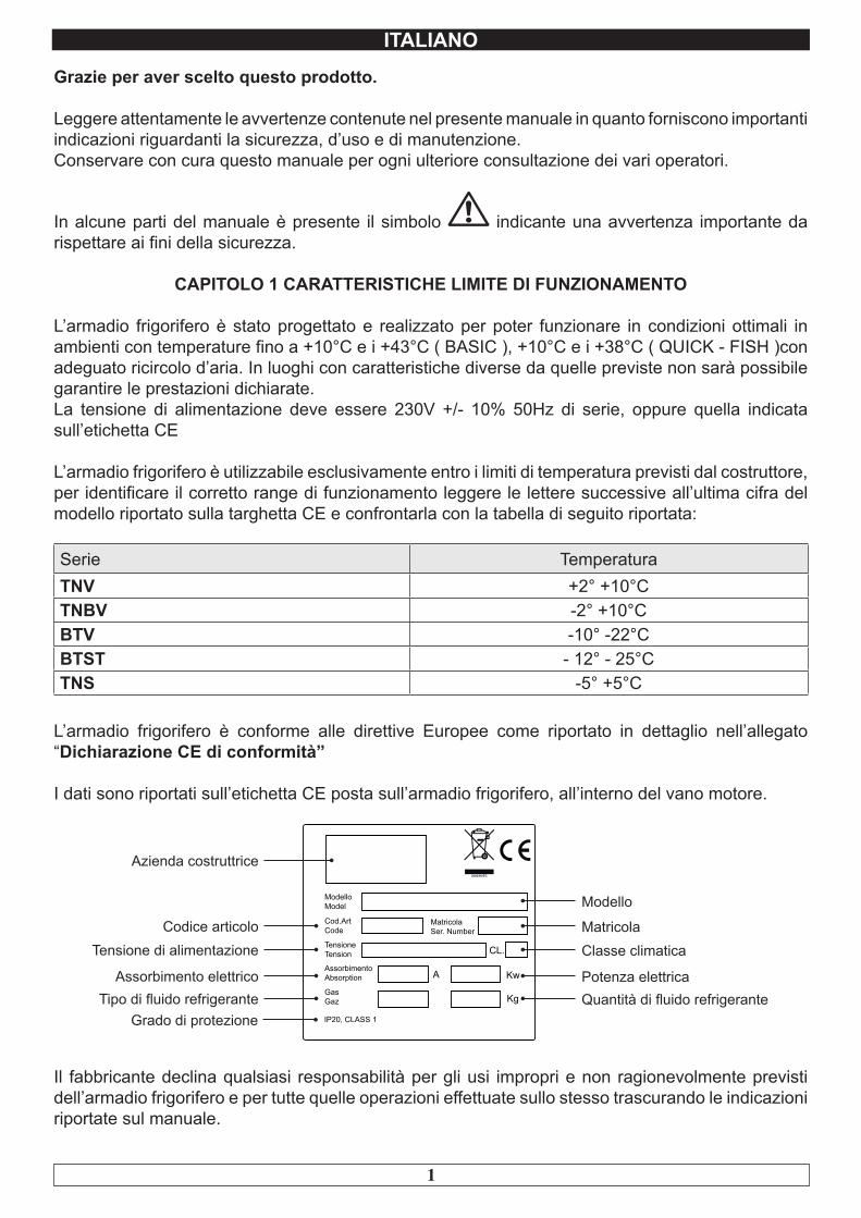
I dati sono riportati sull’etichetta CE posta sull’armadio frigorifero, all’interno del vano motore.
A Kw
Kg
CL.
MatricolaSer. Number
ModelloModel
Cod.ArtCode
TensioneTension
AssorbimentoAbsorption
GasGaz
IP20, CLASS 1
Modello
MatricolaClasse climatica
Potenza elettricaQuantità di fluido refrigerante
Azienda costruttrice
Codice articoloTensione di alimentazione
Assorbimento elettricoTipo di fluido refrigerante
Grado di protezione
Il fabbricante declina qualsiasi responsabilità per gli usi impropri e non ragionevolmente previsti dell’armadio frigorifero e per tutte quelle operazioni effettuate sullo stesso trascurando le indicazioni riportate sul manuale.
2
ITALIANO
Di seguito sono elencate le principali norme di sicurezza generali :
- Non utilizzare o inserire apparecchi elettrici all’interno dei comparti refrigerati se non del tipo consigliato dal produttore- Non toccare l’armadio frigorifero avendo mani o piedi umidi o bagnati- Non usare l’armadio frigorifero a piedi nudi- Non inserire cacciaviti od altro tra le protezioni o le parti in movimento- Non tirare il cavo di alimentazione per scollegare l’armadio frigorifero dalla rete di alimentazione elettrica- L’armadio frigorifero non è adatto all’uso da parte di persone (compresi i bambini) con problemi fisici, mentali o con mancanza di esperienza e conoscenza a meno che esse non siano controllate o istruite all’uso dell’apparecchio da una persona responsabile per la loro sicurezza. I bambini devono essere sorvegliati per assicurarsi che non giochino con l’apparecchio.- Prima di effettuare qualsiasi operazione di pulizia o manutenzione disinserire l’armadio frigorifero dalla rete di alimentazione elettrica spegnendo l’interruttore generale e staccando la spina- In caso di guasto e/o di cattivo funzionamento dell’armadio frigorifero, spegnerlo ed astenersi da qualsiasi tentativo di riparazione o di intervento diretto. E’ necessario rivolgersi esclusivamente a personale qualificato.
L’armadio frigorifero è costituito da una monoscocca modulare rivestita con materiali diversi e isolata con poliuretano espanso a densità 42 kg/m3.
In fase di progettazione e realizzazione sono stati adottati tutti gli accorgimenti per ottenere un armadio frigorifero conforme ai requisiti di sicurezza e igiene quali: gli angoli arrotondati interni, imbutiture con scarico all’esterno dei liquidi di condensa, assenza di superfici rugose, protezioni fisse su componenti mobili o pericolosi.
I prodotti devono essere stivati rispettando i limiti di carico riportati in tabella allo scopo di assicurare una circolazione efficace dell’aria all’interno dell’armadio frigorifero.
Limiti di carico in Kg.Griglia 650x530 20 Vassoio Inox GN 1/1 15Griglia 550x530 20 Vassoio Inox GN 2/1 20Griglia 480x580 15 Vaschetta Inox GN 1/1 15Griglia 480x480 12 Vaschetta Inox GN 2/1 20Cesto in filo 640x530 20 Vaschetta Plastica GN 1/1 10Cesto in filo 528x530 20 Vaschetta Plastica pesce 10Cassetti 530x610 25 Vaschetta Inox pesce 15
L’installazione deve essere effettuata esclusivamente da un tecnico specializzato
1.1 Proibizione della rimozione dei ripari e dei dispositivi di sicurezzaE’ assolutamente vietata la rimozione delle protezioni di sicurezza.
Il fabbricante si esime da qualsiasi responsabilità per incidenti dovuti all’inadempienza del suddetto obbligo.
3
ITALIANO
1.2 Indicazioni sulle operazioni di emergenza in caso di incendio- staccare l’armadio frigorifero dalla presa elettrica oppure interrompere l’alimentazione generale- non utilizzare getti d’acqua- usare estintori a polvere o CO2
CAPITOLO 2 PULIZIA DEL FRIGORIFERO
Poiché nell’armadio frigorifero vanno conservati dei prodotti alimentari è necessaria l’operazione di pulizia ai fini dell’igiene e della tutela della salute. La pulizia dell’armadio frigorifero è già stata effettuata in fabbrica. Si suggerisce tuttavia di effettuare un ulteriore lavaggio delle parti interne prima dell’uso, assicurandosi che il cavo di alimentazione sia scollegato.
2.1 Pulizia del mobile interno ed esternoAllo scopo vengono indicati
- i prodotti di pulizia : acqua e detergenti neutri non abrasivi. NON USARE SOLVENTI E DILUENTI- i metodi di pulizia : lavare le parti interne ed esterne con acqua tiepida e sapone neutro o con panno o spugna con prodotti idonei- la disinfezione : evitare sostanze che possano alterare le caratteristiche organolettiche degli alimenti- la risciacquatura : panno o spugna imbevuti d’acqua tiepida. NON USARE GETTI D’ACQUA- la frequenza : si consiglia settimanale, l’utilizzatore può’ stabilire frequenze diverse in funzione del tipo di alimenti conservati.
IMPORTANTE: Pulire frequentemente le guarnizioni delle porte. Alcuni prodotti conservati protrebbero rilasciare degli enzimi che attaccano la guarnizione deteriorandola molto velocemente. Per la pulizia utilizzare prodotti specifici disponibili a richiesta anche presso la nostra rete commerciale.
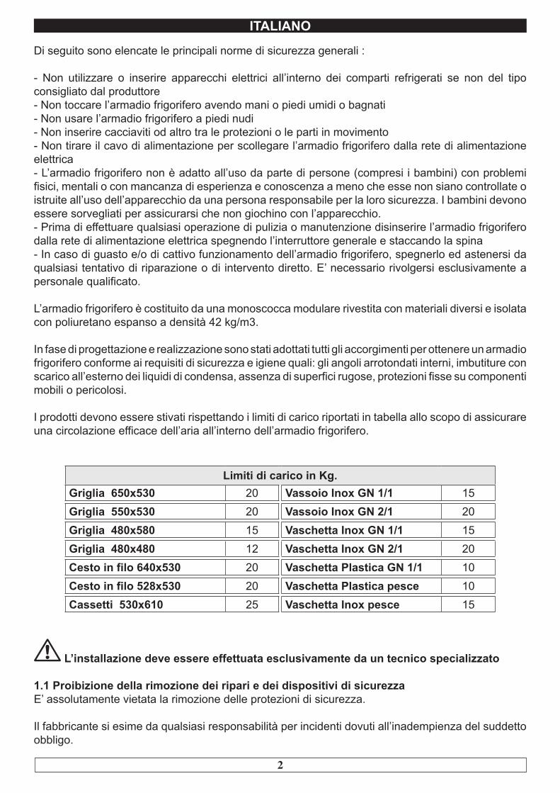
2.2 Pulizia del condensatoreL’efficienza dell’armadio frigorifero è compromessa dall’intasamento del condensatore per cui è necessario provvedere alla pulizia dello stesso con frequenza mensile. Prima di effettuare questa operazione spegnere l’armadio frigorifero, disinserire il cavo di alimentazione e procedere come segue :
Motore in basso - aprire il frontale portacomandi svitando le apposite viti e facendolo ruotare sulle cerniere poste in basso.
Motore in alto - per i modelli con frontale fisso non ribaltabile, salire su una scaletta sicura e accedere direttamente al condensatore posto sulla parte superiore l’armadio frigorifero.
Con l’ausilio di un getto d’aria o pennello asciutto eliminare, con movimento verticale ( Fig. 1 ), la polvere e la lanuggine depositata sulle alette. Nel caso di depositi untuosi si consiglia l’impiego di un pennello imbevuto di appositi detergenti. Per i modelli con frontale ribaltabile, svitare la vite di blocco e ruotare il frontale sulle cerniere poste in alto. A questo punto procedere alla pulizia come per i modelli a frontale fisso.
Ad operazione ultimata avviare nuovamente l’armadio frigorifero.
Durante questa operazione usare i seguenti dispositivi di protezione individuali : occhiali, maschera di protezione delle vie respiratorie, guanti resistenti agli agenti chimici ( benzine-alcool ).
ALCOOL
Fig.1
4
ITALIANO
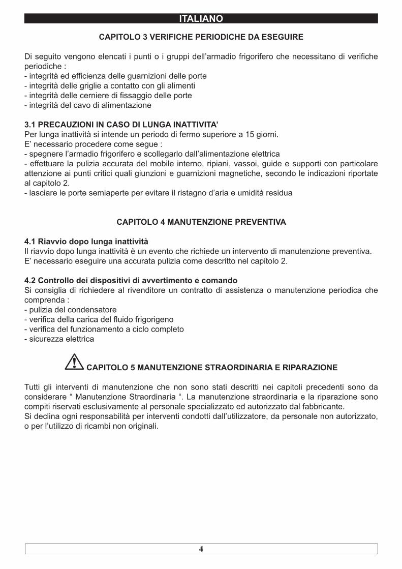
CAPITOLO 3 VERIFICHE PERIODICHE DA ESEGUIRE
Di seguito vengono elencati i punti o i gruppi dell’armadio frigorifero che necessitano di verifiche periodiche :- integrità ed efficienza delle guarnizioni delle porte- integrità delle griglie a contatto con gli alimenti- integrità delle cerniere di fissaggio delle porte- integrità del cavo di alimentazione
3.1 PRECAUZIONI IN CASO DI LUNGA INATTIVITA’Per lunga inattività si intende un periodo di fermo superiore a 15 giorni.E’ necessario procedere come segue :- spegnere l’armadio frigorifero e scollegarlo dall’alimentazione elettrica - effettuare la pulizia accurata del mobile interno, ripiani, vassoi, guide e supporti con particolare attenzione ai punti critici quali giunzioni e guarnizioni magnetiche, secondo le indicazioni riportate al capitolo 2.- lasciare le porte semiaperte per evitare il ristagno d’aria e umidità residua
CAPITOLO 4 MANUTENZIONE PREVENTIVA
4.1 Riavvio dopo lunga inattivitàIl riavvio dopo lunga inattività è un evento che richiede un intervento di manutenzione preventiva.E’ necessario eseguire una accurata pulizia come descritto nel capitolo 2.
4.2 Controllo dei dispositivi di avvertimento e comandoSi consiglia di richiedere al rivenditore un contratto di assistenza o manutenzione periodica che comprenda :- pulizia del condensatore- verifica della carica del fluido frigorigeno- verifica del funzionamento a ciclo completo- sicurezza elettrica
CAPITOLO 5 MANUTENZIONE STRAORDINARIA E RIPARAZIONE
Tutti gli interventi di manutenzione che non sono stati descritti nei capitoli precedenti sono da considerare “ Manutenzione Straordinaria “. La manutenzione straordinaria e la riparazione sono compiti riservati esclusivamente al personale specializzato ed autorizzato dal fabbricante.Si declina ogni responsabilità per interventi condotti dall’utilizzatore, da personale non autorizzato, o per l’utilizzo di ricambi non originali.
5
ITALIANO
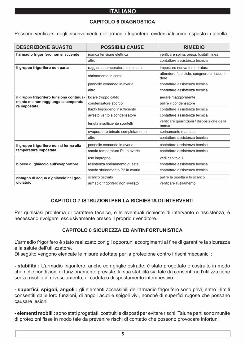
CAPITOLO 6 DIAGNOSTICA
Possono verificarsi degli inconvenienti, nell’armadio frigorifero, evidenziati come esposto in tabella :
DESCRIZIONE GUASTO POSSIBILI CAUSE RIMEDIOl’armadio frigorifero non si accende manca tensione elettrica verificare spina, presa, fusibili, linea
altro contattare assistenza tecnica
il gruppo frigorifero non parte raggiunta temperatura impostata impostare nuova temperatura
sbrinamento in corso attendere fine ciclo, spegnere e riaccen-dere
pannello comando in avaria contattare assistenza tecnicaaltro contattare assistenza tecnica
il gruppo frigorifero funziona continua-mente ma non raggiunge la temperatu-ra impostata
locale troppo caldo aerare maggiormentecondensatore sporco pulire il condensatorefluido frigorigeno insufficiente contattare assistenza tecnicaarresto ventola condensatore contattare assistenza tecnica
tenuta insufficiente sportelli verificare guarnizioni / disposizione della merce
evaporatore brinato completamente sbrinamento manualealtro contattare assistenza tecnica
il gruppo frigorifero non si ferma alla temperatura impostata
pannello comando in avaria contattare assistenza tecnicasonda temperatura P1 in avaria contattare assistenza tecnica
blocco di ghiaccio sull’evaporatoreuso improprio vedi capitolo 1.resistenza sbrinamento guasta contattare assistenza tecnicasonda sbrinamento P2 in avaria contattare assistenza tecnica
ristagno di acqua o ghiaccio nel goc-ciolatoio
scarico ostruito pulire la pipetta e lo scaricoarmadio frigorifero non livellato verificare livellamento
CAPITOLO 7 ISTRUZIONI PER LA RICHIESTA DI INTERVENTI
Per qualsiasi problema di carattere tecnico, e le eventuali richieste di intervento o assistenza, è necessario rivolgersi esclusivamente presso il proprio rivenditore.
CAPITOLO 8 SICUREZZA ED ANTINFORTUNISTICA
L’armadio frigorifero è stato realizzato con gli opportuni accorgimenti al fine di garantire la sicurezza e la salute dell’utilizzatore.Di seguito vengono elencate le misure adottate per la protezione contro i rischi meccanici :
- stabilità : L’armadio frigorifero, anche con griglie estratte, è stato progettato e costruito in modo che nelle condizioni di funzionamento previste, la sua stabilità sia tale da consentirne l’utilizzazione senza rischio di rovesciamento, di caduta o di spostamento intempestivo
- superfici, spigoli, angoli : gli elementi accessibili dell’armadio frigorifero sono privi, entro i limiti consentiti dalle loro funzioni, di angoli acuti e spigoli vivi, nonché di superfici rugose che possano causare lesioni
- elementi mobili : sono stati progettati, costruiti e disposti per evitare rischi. Talune parti sono munite di protezioni fisse in modo tale da prevenire rischi di contatto che possono provocare infortuni
6
ITALIANO
Di seguito vengono elencate le misure adottate per la protezione contro altri rischi :
- energia elettrica : L’armadio frigorifero è stato progettato, costruito ed equipaggiato in modo da prevenire i rischi elettrici, nel rispetto della normativa specifica vigente
- rumore : L’armadio frigorifero è stato progettato e costruito in modo tale che i rischi dovuti all’emissione di rumore aereo siano ridotti al livello minimo
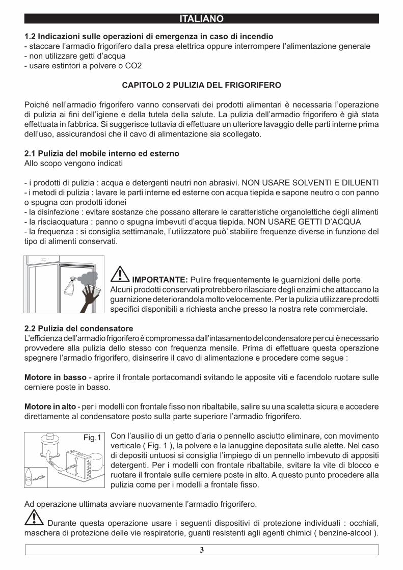
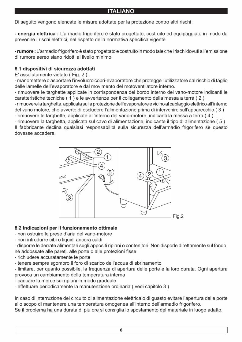
8.1 dispositivi di sicurezza adottatiE’ assolutamente vietato ( Fig. 2 ) :- manomettere o asportare l’involucro copri-evaporatore che protegge l’utilizzatore dal rischio di taglio delle lamelle dell’evaporatore e dal movimento del motoventilatore interno.- rimuovere le targhette applicate in corrispondenza del bordo interno del vano-motore indicanti le caratteristiche tecniche ( 1 ) e le avvertenze per il collegamento della messa a terra ( 2 )- rimuovere la targhetta, applicata sulla protezione dell’evaporatore e vicino al cablaggio elettrico all’interno del vano motore, che avverte di escludere l’alimentazione prima di intervenire sull’apparecchio ( 3 )- rimuovere le targhette, applicate all’interno del vano-motore, indicanti la messa a terra ( 4 )- rimuovere la targhetta, applicata sul cavo di alimentazione, indicante il tipo di alimentazione ( 5 )Il fabbricante declina qualsiasi responsabilità sulla sicurezza dell’armadio frigorifero se questo dovesse accadere.
12
3
34
5 4 2 1
Fig.2
8.2 Indicazioni per il funzionamento ottimale- non ostruire le prese d’aria del vano-motore- non introdurre cibi o liquidi ancora caldi- disporre le derrate alimentari sugli appositi ripiani o contenitori. Non disporle direttamente sul fondo, né addossate alle pareti, alle porte o alle protezioni fisse- richiudere accuratamente le porte- tenere sempre sgombro il foro di scarico dell’acqua di sbrinamento- limitare, per quanto possibile, la frequenza di apertura delle porte e la loro durata. Ogni apertura provoca un cambiamento della temperatura interna- caricare la merce sui ripiani in modo graduale- effettuare periodicamente la manutenzione ordinaria ( vedi capitolo 3 )
In caso di interruzione del circuito di alimentazione elettrica o di guasto evitare l’apertura delle porte allo scopo di mantenere una temperatura omogenea all’interno dell’armadio frigorifero. Se il problema ha una durata di più ore si consiglia lo spostamento del materiale in luogo adatto.
7
ITALIANO
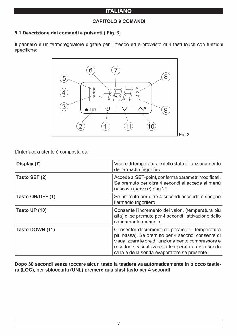
CAPITOLO 9 COMANDI
9.1 Descrizione dei comandi e pulsanti ( Fig. 3)
Il pannello è un termoregolatore digitale per il freddo ed è provvisto di 4 tasti touch con funzioni specifiche:
Fig.3
L’interfaccia utente è composta da:
Display (7) Visore di temperatura e dello stato di funzionamento dell’armadio frigorifero
Tasto SET (2) Accede al SET-point, conferma parametri modificati. Se premuto per oltre 4 secondi si accede ai menù nascosti (service) pag.29
Tasto ON/OFF (1) Se premuto per oltre 4 secondi accende o spegne l’armadio frigorifero
Tasto UP (10) Consente l’incremento dei valori, (temperatura più alta) e, se premuto per 4 secondi l’attivazione dello sbrinamento manuale.
Tasto DOWN (11) Consente il decremento dei parametri, (temperatura più bassa). Se premuto per 4 secondi consente di visualizzare le ore di funzionamento compressore e resettarle, visualizzare la temperatura della sonda cella e della sonda evaporatore se presente.
Dopo 30 secondi senza toccare alcun tasto la tastiera va automaticamente in blocco tastie-ra (LOC), per sbloccarla (UNL) premere qualsiasi tasto per 4 secondi
8
ITALIANO
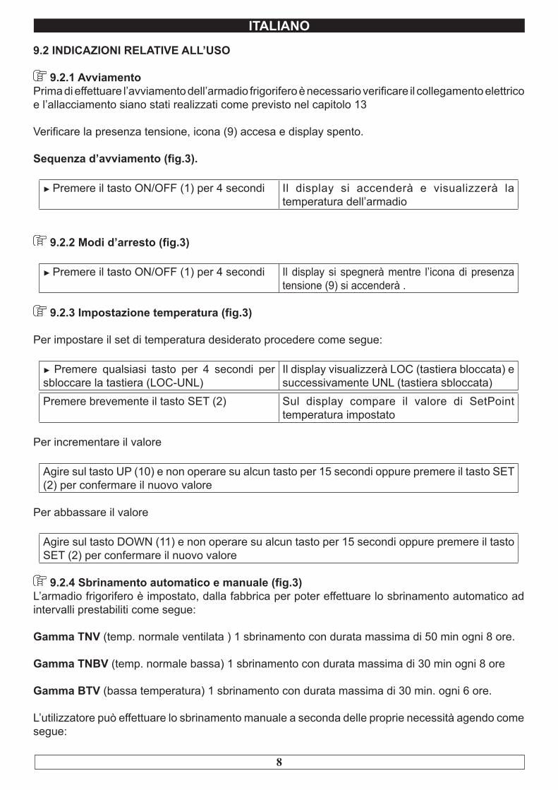
9.2 INDICAZIONI RELATIVE ALL’USO
9.2.1 AvviamentoPrima di effettuare l’avviamento dell’armadio frigorifero è necessario verificare il collegamento elettrico e l’allacciamento siano stati realizzati come previsto nel capitolo 13
Verificare la presenza tensione, icona (9) accesa e display spento.
Sequenza d’avviamento (fig.3).
► Premere il tasto ON/OFF (1) per 4 secondi Il display si accenderà e visualizzerà la temperatura dell’armadio
9.2.2 Modi d’arresto (fig.3)
► Premere il tasto ON/OFF (1) per 4 secondi Il display si spegnerà mentre l’icona di presenza tensione (9) si accenderà .
9.2.3 Impostazione temperatura (fig.3)
Per impostare il set di temperatura desiderato procedere come segue:
► Premere qualsiasi tasto per 4 secondi per sbloccare la tastiera (LOC-UNL)
Il display visualizzerà LOC (tastiera bloccata) e successivamente UNL (tastiera sbloccata)
Premere brevemente il tasto SET (2) Sul display compare il valore di SetPoint temperatura impostato
Per incrementare il valore
Agire sul tasto UP (10) e non operare su alcun tasto per 15 secondi oppure premere il tasto SET (2) per confermare il nuovo valore
Per abbassare il valore
Agire sul tasto DOWN (11) e non operare su alcun tasto per 15 secondi oppure premere il tasto SET (2) per confermare il nuovo valore
9.2.4 Sbrinamento automatico e manuale (fig.3)L’armadio frigorifero è impostato, dalla fabbrica per poter effettuare lo sbrinamento automatico ad intervalli prestabiliti come segue:
Gamma TNV (temp. normale ventilata ) 1 sbrinamento con durata massima di 50 min ogni 8 ore.
Gamma TNBV (temp. normale bassa) 1 sbrinamento con durata massima di 30 min ogni 8 ore
Gamma BTV (bassa temperatura) 1 sbrinamento con durata massima di 30 min. ogni 6 ore.
L’utilizzatore può effettuare lo sbrinamento manuale a seconda delle proprie necessità agendo come segue:
9
ITALIANO
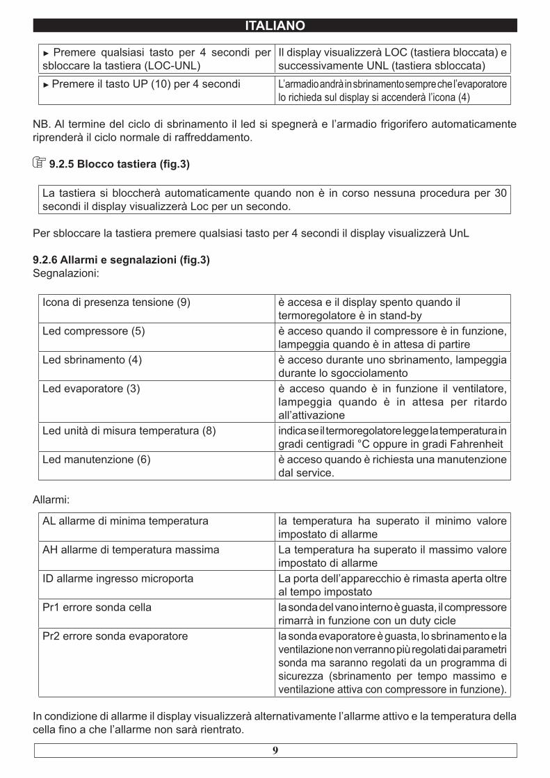
► Premere qualsiasi tasto per 4 secondi per sbloccare la tastiera (LOC-UNL)
Il display visualizzerà LOC (tastiera bloccata) e successivamente UNL (tastiera sbloccata)
► Premere il tasto UP (10) per 4 secondi L’armadio andrà in sbrinamento sempre che l’evaporatore lo richieda sul display si accenderà l’icona (4)
NB. Al termine del ciclo di sbrinamento il led si spegnerà e l’armadio frigorifero automaticamente riprenderà il ciclo normale di raffreddamento.
9.2.5 Blocco tastiera (fig.3)
La tastiera si bloccherà automaticamente quando non è in corso nessuna procedura per 30 secondi il display visualizzerà Loc per un secondo.
Per sbloccare la tastiera premere qualsiasi tasto per 4 secondi il display visualizzerà UnL
9.2.6 Allarmi e segnalazioni (fig.3)Segnalazioni:
Icona di presenza tensione (9) è accesa e il display spento quando il termoregolatore è in stand-by
Led compressore (5) è acceso quando il compressore è in funzione, lampeggia quando è in attesa di partire
Led sbrinamento (4) è acceso durante uno sbrinamento, lampeggia durante lo sgocciolamento
Led evaporatore (3) è acceso quando è in funzione il ventilatore, lampeggia quando è in attesa per ritardo all’attivazione
Led unità di misura temperatura (8) indica se il termoregolatore legge la temperatura in gradi centigradi °C oppure in gradi Fahrenheit
Led manutenzione (6) è acceso quando è richiesta una manutenzione dal service.
Allarmi:
AL allarme di minima temperatura la temperatura ha superato il minimo valore impostato di allarme
AH allarme di temperatura massima La temperatura ha superato il massimo valore impostato di allarme
ID allarme ingresso microporta La porta dell’apparecchio è rimasta aperta oltre al tempo impostato
Pr1 errore sonda cella la sonda del vano interno è guasta, il compressore rimarrà in funzione con un duty cicle
Pr2 errore sonda evaporatore la sonda evaporatore è guasta, lo sbrinamento e la ventilazione non verranno più regolati dai parametri sonda ma saranno regolati da un programma di sicurezza (sbrinamento per tempo massimo e ventilazione attiva con compressore in funzione).
In condizione di allarme il display visualizzerà alternativamente l’allarme attivo e la temperatura della cella fino a che l’allarme non sarà rientrato.
10
ITALIANO
CAPITOLO 10 LIVELLO DI RUMOROSITA’
L’armadio frigorifero è stato progettato e costruito in modo tale che i rischi dovuti all’emissione di rumore aereo siano ridotti al livello minimo (vedi schede tecniche).
CAPITOLO 11 MATERIALI E FLUIDI IMPIEGATI
I materiali a contatto o che possono venire a contatto con i prodotti alimentari sono conformi alle direttive in materia.L’armadio frigorifero è stato progettato e costruito in modo tale che detti materiali possano essere puliti prima di ogni utilizzo.I fluidi frigorigeni utilizzati R404A/R290 sono conformi alle disposizioni di legge in materia (vedi Tabella 1).L’ R404A è un gas fluorurato trattato dal Protocollo di Kyoto ha un potenziale GWP di 3300
Per gli armadi frigoriferi contenenti R290: l’R290 (Propano) è un gas naturale senza alcun effetto sull’ambiente ma infiammabile è per questo contenuto nell’impianto in quantità minima prescritta dalle norme sui gas infiammabili e sigillato ermeticamente. Prima di ogni intervento sul sistema frigorifero leggere attentamente l’allegato AVVERTENZE PER INTERVENTI DI RIPARAZIONE SU APPARECCHI CON GAS REFRIGERANTE R290 (PROPANO) in dotazione con il manuale uso e manutenzione.
Il simbolo indica che questo prodotto non deve essere trattato come rifiuto domestico.
Per prevenire potenziali conseguenze negative per l’ambiente e per la salute, accertarsi che questo prodotto venga correttamente smaltito e riciclato.
Per maggiori informazioni relative allo smaltimento ed al riciclaggio di questo prodotto, contattate il vostro Distributore, il Servizio post vendita oppure il Servizio trattamento dei rifiuti.
11
ITALIANO
CAPITOLO 12 TRASPORTO E MOVIMENTAZIONE
Il trasporto e la movimentazione dell’armadio frigorifero devono esclusivamente avvenire mantenendo la posizione verticale, rispettando le indicazioni poste sull’imballo.
Il fabbricante si esime da qualsiasi responsabilità per inconvenienti dovuti al trasporto effettuato in condizioni diverse da quelle specificate in precedenza. Gli accessori a corredo dell’armadio frigorifero ( guide, griglie, vaschette, vassoi ) sono confezionati a parte e posizionati all’interno del mobile.
L’armadio frigorifero è fissato su un basamento di legno mediante viti e confezionata con imballi in polietilene, cartone, gabbia o cassa.
Per quanto riguarda lo smaltimento dell’imballo è necessario fare riferimento alle normative vigenti nel vostro paese.
La movimentazione dell’armadio frigorifero deve essere effettuata utilizzando un carrello sollevatore o transpallets provvisto di forche idonee ( lunghezza almeno pari a 2/3 del mobile ) .Le dimensioni e le masse degli armadi frigoriferi imballati sono rappresentate in Tabella1.I limiti di impilabilità e la posizione del baricentro sono indicati sulla targhetta dell’imballo.
12.1 Operazioni di posizionamentoPoiché l’errato posizionamento dell’armadio frigorifero può recare danno allo stesso, pregiudicarne il buon funzionamento e dar luogo a rischi per il personale, l’installatore deve rispettare le seguenti norme generali :
- posizionare l’armadio frigorifero mantenendo una distanza minima di cm 3 da qualsiasi parete- l’ambiente deve essere sufficientemente aerato- posizionare l’armadio frigorifero lontano da fonti di calore- evitare l’esposizione solare diretta- rimuovere l’imballo di polietilene, cartone o legno
Il polietilene è pericoloso per i bambini
- rimuovere eventuali accessori a corredo esterni
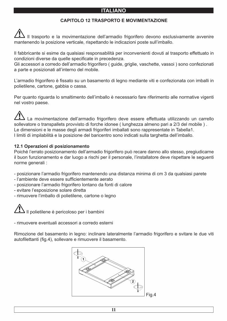
Rimozione del basamento in legno: inclinare lateralmente l’armadio frigorifero e svitare le due viti autofilettanti (fig.4), sollevare e rimuovere il basamento.
Fig.4
12
ITALIANO
utilizzare guanti di protezione nel maneggiare l’imballo in legno e il basamento in legno.
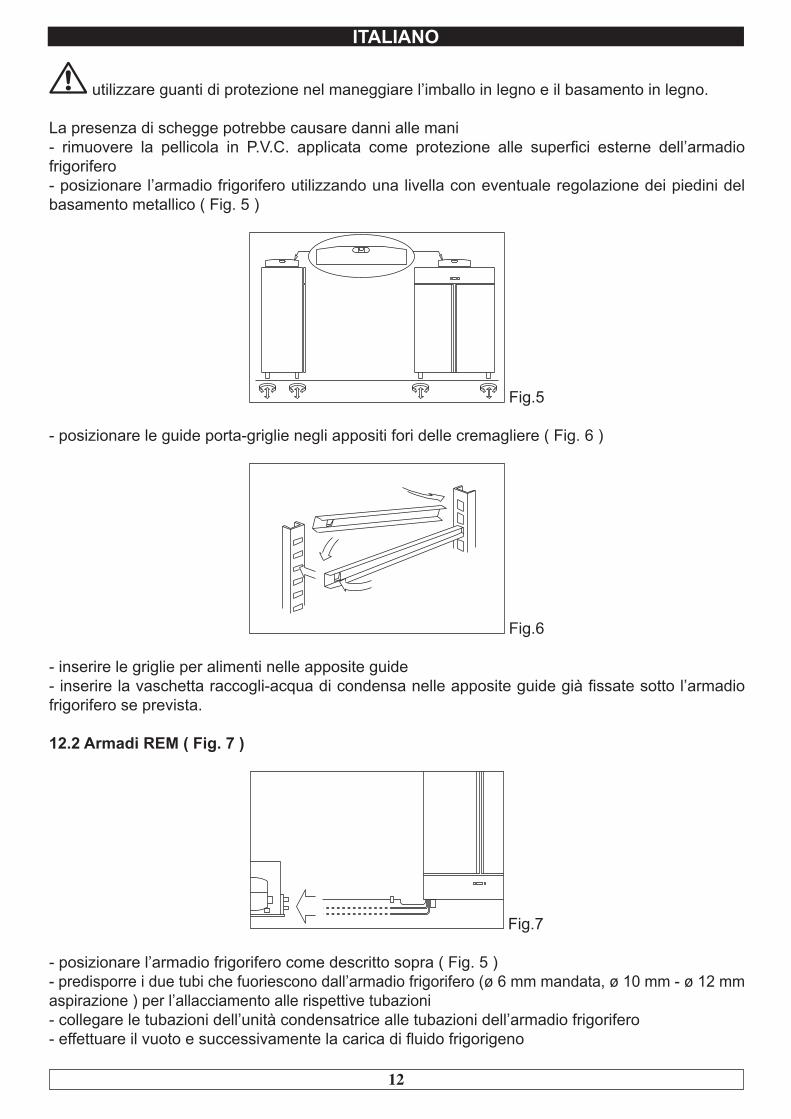
La presenza di schegge potrebbe causare danni alle mani- rimuovere la pellicola in P.V.C. applicata come protezione alle superfici esterne dell’armadio frigorifero- posizionare l’armadio frigorifero utilizzando una livella con eventuale regolazione dei piedini del basamento metallico ( Fig. 5 )
Fig.5
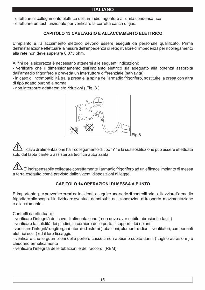
- posizionare le guide porta-griglie negli appositi fori delle cremagliere ( Fig. 6 )
Fig.6
- inserire le griglie per alimenti nelle apposite guide- inserire la vaschetta raccogli-acqua di condensa nelle apposite guide già fissate sotto l’armadio frigorifero se prevista.
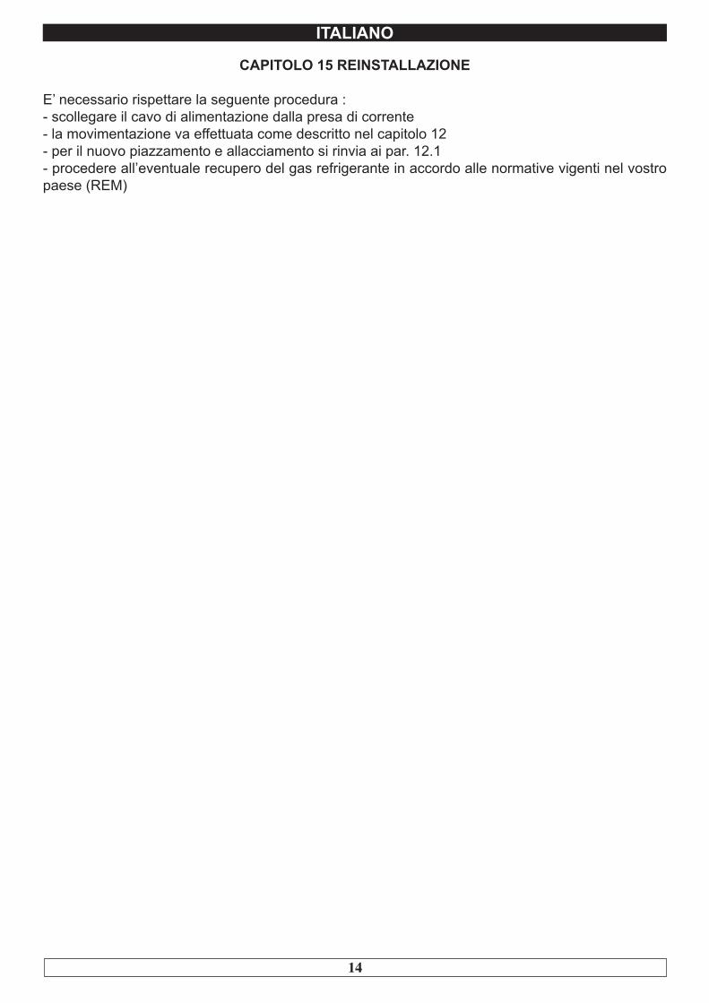
12.2 Armadi REM ( Fig. 7 )
Fig.7
- posizionare l’armadio frigorifero come descritto sopra ( Fig. 5 )- predisporre i due tubi che fuoriescono dall’armadio frigorifero (ø 6 mm mandata, ø 10 mm - ø 12 mm aspirazione ) per l’allacciamento alle rispettive tubazioni - collegare le tubazioni dell’unità condensatrice alle tubazioni dell’armadio frigorifero- effettuare il vuoto e successivamente la carica di fluido frigorigeno
13
ITALIANO
- effettuare il collegamento elettrico dell’armadio frigorifero all’unità condensatrice- effettuare un test funzionale per verificare la corretta carica di gas.
CAPITOLO 13 CABLAGGIO E ALLACCIAMENTO ELETTRICO
L’impianto e l’allacciamento elettrico devono essere eseguiti da personale qualificato. Prima dell’installazione effettuare la misura dell’impedenza di rete; il valore di impedenza per il collegamento alla rete non deve superare 0,075 ohm.
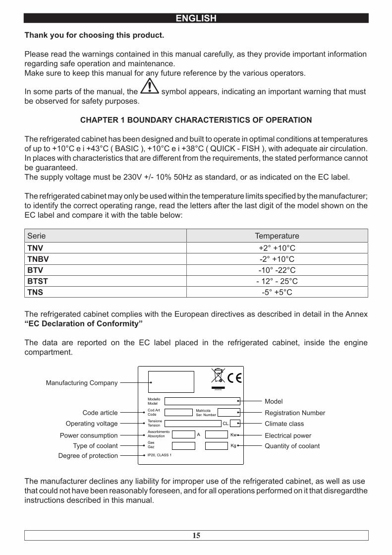
Ai fini della sicurezza è necessario attenersi alle seguenti indicazioni:- verificare che il dimensionamento dell’impianto elettrico sia adeguato alla potenza assorbita dall’armadio frigorifero e preveda un interruttore differenziale (salvavita)- in caso di incompatibilità tra la presa e la spina dell’armadio frigorifero, sostituire la presa con altra di tipo adatto purché a norma- non interporre adattatori e/o riduzioni ( Fig. 8 )
Fig.8
Il cavo di alimentazione ha il collegamento di tipo “Y “ e la sua sostituzione può essere effettuata solo dal fabbricante o assistenza tecnica autorizzata
E’ indispensabile collegare correttamente l’armadio frigorifero ad un efficace impianto di messa a terra eseguito come previsto dalle vigenti disposizioni di legge.
CAPITOLO 14 OPERAZIONI DI MESSA A PUNTO
E’ importante, per prevenire errori ed incidenti, eseguire una serie di controlli prima di avviare l’armadio frigorifero allo scopo di individuare eventuali danni subiti nelle operazioni di trasporto, movimentazione e allacciamento.
Controlli da effettuare:- verificare l’integrità del cavo di alimentazione ( non deve aver subito abrasioni o tagli )- verificare la solidità dei piedini, le cerniere delle porte, i supporti dei ripiani- verificare l’integrità degli organi interni ed esterni ( tubazioni, elementi radianti, ventilatori, componenti elettrici ecc. ) ed il loro fissaggio- verificare che le guarnizioni delle porte e cassetti non abbiano subito danni ( tagli o abrasioni ) e chiudano ermeticamente- verificare l’integrità delle tubazioni e dei raccordi (REM)
14
ITALIANO
CAPITOLO 15 REINSTALLAZIONE
E’ necessario rispettare la seguente procedura :- scollegare il cavo di alimentazione dalla presa di corrente- la movimentazione va effettuata come descritto nel capitolo 12- per il nuovo piazzamento e allacciamento si rinvia ai par. 12.1- procedere all’eventuale recupero del gas refrigerante in accordo alle normative vigenti nel vostro paese (REM)
15
ENGLISH
Thank you for choosing this product.
Please read the warnings contained in this manual carefully, as they provide important informationregarding safe operation and maintenance.Make sure to keep this manual for any future reference by the various operators.
In some parts of the manual, the symbol appears, indicating an important warning that mustbe observed for safety purposes.
CHAPTER 1 BOUNDARY CHARACTERISTICS OF OPERATION
The refrigerated cabinet has been designed and built to operate in optimal conditions at temperatures of up to +10°C e i +43°C ( BASIC ), +10°C e i +38°C ( QUICK - FISH ), with adequate air circulation. In places with characteristics that are different from the requirements, the stated performance cannot be guaranteed.The supply voltage must be 230V +/- 10% 50Hz as standard, or as indicated on the EC label.
The refrigerated cabinet may only be used within the temperature limits specified by the manufacturer; to identify the correct operating range, read the letters after the last digit of the model shown on the EC label and compare it with the table below:
Serie TemperatureTNV +2° +10°CTNBV -2° +10°CBTV -10° -22°CBTST - 12° - 25°CTNS -5° +5°C
The refrigerated cabinet complies with the European directives as described in detail in the Annex “EC Declaration of Conformity”
The data are reported on the EC label placed in the refrigerated cabinet, inside the engine compartment.
A Kw
Kg
CL.
MatricolaSer. Number
ModelloModel
Cod.ArtCode
TensioneTension
AssorbimentoAbsorption
GasGaz
IP20, CLASS 1
Model
Registration NumberClimate class
Electrical powerQuantity of coolant
Manufacturing Company
Code articleOperating voltage
Power consumptionType of coolant
Degree of protection
The manufacturer declines any liability for improper use of the refrigerated cabinet, as well as usethat could not have been reasonably foreseen, and for all operations performed on it that disregardthe instructions described in this manual.
16
ENGLISH
The main general safety standards are listed below:
- Do not use or place electrical devices inside the refrigerated compartments if they are not of thetype recommended by the manufacturer- Do not touch the refrigerated cabinet with damp or wet hands or feet- Do not use the refrigerated cabinet barefoot- Do not insert screwdrivers or other objects between the guards or moving parts- Do not pull the power cord to unplug the refrigerated cabinet from the electricity network- The refrigerated cabinet is not intended to be used by persons (including children) with physical ormental problems, or lack of experience and knowledge, unless they are controlled or instructed inusing the unit by a person responsible for their safety. Children must be supervised to ensure thatthey do not play with the appliance.- Before carrying out any cleaning or maintenance, disconnect the refrigerated cabinet from the mains power supply by turning off the main switch and pulling the plug- In the event of failure and/or malfunction of the refrigerated cabinet, turn it off and to refrain fromany attempt to repair or intervene directly. It is necessary to exclusively contact a qualified technician.
The refrigerated cabinet is composed of a modular monocoque coated with different materials andinsulated with polyurethane foam of density 42 kg/m3.
In the design and construction, all measures have been adopted to ensure a refrigerated cabinetthat complies with safety and hygiene requirements, such as: rounded interior corners, deep drawing with drain on the outside for the condensate liquids, no rough surfaces, fixed guards on moving ordangerous parts.
The products must be stored in observance of the load limits given in the table, in order to ensurean efficient circulation of air inside the refrigerated cabinet.
Load limit expressed in Kg.Grille 650x530 20 Stainless Steel Tray GN 1/1 15Grille 550x530 20 Stainless Steel Tray GN 2/1 20Grille 480x580 15 Stainless Steel Basin Inox GN 1/1 15Grille 480x480 12 Stainless Steel Basin Inox GN 2/1 20Wire basket 640x530 20 Plastic Basin GN 1/1 10Wire basket 528x530 20 Plastic Basin for Fish 10Drawers 530x610 25 Stainless Steel Basin for Fish 15
The installation must be performed exclusively by a qualified technician
1.1 It is prohibited to remove the guards and safety devicesIt is absolutely forbidden to remove safety guards.
The manufacturer disclaims any liability for accidents due to failure to comply with this obligation.
17
ENGLISH
1.2 Information on emergency operations in the event of fire- disconnect the refrigerated cabinet from the electrical outlet or cut off the main power supply- do not use water jets- use dry chemical or CO2 extinguishers
CHAPTER 2 CLEANING THE REFRIGERATOR
Since the refrigerated cabinet will be used to store food, cleaning is necessary for hygiene and health protection purposes. The cleaning of the refrigerated cabinet has already been carried out at thefactory. It is suggested, however, to carry out an additional cleaning of the internal parts before use, making sure that the power cord is unplugged.
2.1 Cleaning the interior and exterior cabinetFor this purpose the following are indicated- the cleaning products: water and mild, non-abrasive detergents. DO NOT USE SOLVENTS ANDTHINNERS- methods for cleaning: wash the interior and exterior parts with warm water and mild soap or with a cloth or sponge with suitable products- disinfection: avoid substances that can alter the organoleptic characteristics of the food- rinsing: cloth or sponge soaked in warm water. DO NOT USE WATER JETS- frequency: weekly is recommended, the user can set different frequencies depending on the typeof food being stored.
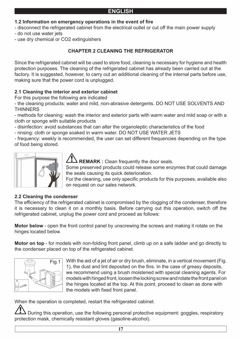
REMARK : Clean frequently the door seals.Some preserved products could release some enzymes that could damage the seals causing its quick deterioration. For the cleaning, use only specific products for this purposes, available also on request on our sales network.
2.2 Cleaning the condenserThe efficiency of the refrigerated cabinet is compromised by the clogging of the condenser, therefore it is necessary to clean it on a monthly basis. Before carrying out this operation, switch off the refrigerated cabinet, unplug the power cord and proceed as follows:
Motor below - open the front control panel by unscrewing the screws and making it rotate on thehinges located below.
Motor on top - for models with non-folding front panel, climb up on a safe ladder and go directly tothe condenser placed on top of the refrigerated cabinet.
With the aid of a jet of air or dry brush, eliminate, in a vertical movement (Fig. 1), the dust and lint deposited on the fins. In the case of greasy deposits,we recommend using a brush moistened with special cleaning agents. Formodels with hinged front, loosen the locking screw and rotate the front panel on the hinges located at the top. At this point, proceed to clean as done withthe models with fixed front panel.
When the operation is completed, restart the refrigerated cabinet.
During this operation, use the following personal protective equipment: goggles, respiratoryprotection mask, chemically resistant gloves (gasoline-alcohol).
ALCOOL
Fig.1

18
ENGLISH
CHAPTER 3 PERIODIC CHECKS TO BE CARRIED OUT
The following are the points or units of the refrigerated cabinet that require periodic checks:- integrity and efficiency of door seals- integrity of the grilles in contact with food- integrity of the fixing hinges of the doors- integrity of the power cord
3.1 PRECAUTIONS IN CASE OF LONG PERIODS OF INACTIVITYA long period of inactivity is defined as a stoppage of more than 15 days.It is necessary to proceed as follows:- switch off the refrigerated cabinet and disconnect it from the power supply- carry out a thorough cleaning of the interior cabinet, shelves, trays, guides and supports, payingspecial attention to critical points such as the joints and magnetic gaskets, as indicated in Chapter 2.- leave the door partly open to prevent air stagnation and residual humidity
CHAPTER 4 PREVENTIVE MAINTENANCE
4.1 Restarting after a long period of inactivityRestarting after long inactivity is an event that requires preventive maintenance.It is necessary to perform a thorough cleaning as described in chapter 2.
4.2 Control of the warning and control devicesWe recommend that you contact your dealer for a service or maintenance contract that includes:- cleaning of the condenser- verification of the coolant load- verification of the full cycle operation- electrical safety
CHAPTER 5 EXTRAORDINARY MAINTENANCE AND REPAIR
All maintenance activities that have not been described in previous chapters are considered“Extraordinary Maintenance.” Extraordinary maintenance and repair are tasks reserved exclusivelyto the specialist personnel authorized by the manufacturer.No liability is accepted for actions carried out by the user, by unauthorized personnel, or with the use of non-original replacement parts.

19
ENGLISH
CHAPTER 6 TROUBLESHOOTING
Problems may occur, in the refrigerated cabinet, identified as shown in the table:
TROUBLE DESCRIPTION POSSIBLE CAUSES HOW TO REPAIR ITthe refrigerated cabinet does not turnon
no power supply check the plug, socket, fuses, lineother contact technical support
the refrigeration unit does not start the set temperature has been reached set new temperature
defrosting in progress wait until the end of cycle / turn power offand on again
command panel failed contact technical supportother contact technical support
the refrigeration unit runs continuou-sly but does not reach the settemperature
location is too hot aerate morecondenser is dirty clean the condenserinsufficient coolant contact technical supportstop the condenser fan contact technical supportinsufficient sealing of doors check the seals / provision of goodsevaporator completely frosted manual defrostingother contact technical support
the refrigeration unit does not stop atthe set temperature
command panel failed contact technical supportP1 temperature sensor failed contact technical support
block of ice on the evaporatormisuse see chapter 1.defrost heater fault contact technical supportdefrost probe P2 damaged contact technical support
accumulation of water or ice in thedrip tray
drain clogged clean the pipette and the drainrefrigerated cabinet is not level check levelling
CHAPTER 7 INSTRUCTIONS FOR REQUESTING ASSISTANCE
For any technical problem, and any requests for assistance or service, you must exclusively contact your own dealer.
CHAPTER 8 SAFETY AND ACCIDENT PREVENTION
The refrigerated cabinet has been built with suitable measures to ensure the safety and health ofthe user.The following are the measures taken to protect against mechanical risks:
- stability: The refrigerated cabinet, even with the grilles removed, has been designed and built insuch a way that under the intended operating conditions, its stability is suitable for use without riskof overturning, falling or unexpected movement
- surfaces, edges, corners: the accessible parts of the refrigerated cabinet are, within the limitsallowed by their functions, free of sharp angles and sharp edges, as well as rough surfaces likely to cause injury
- moving parts: were designed, constructed and arranged to avoid risks. Certain parts are equipped with fixed guards so as to prevent risks of contact which may result in injury
20
ENGLISH
The following are the measures taken to protect against other risks:
- electricity: The refrigerated cabinet has been designed, built and equipped so as to prevent risks from electricity, in accordance with the specific legislation in force
- noise: The refrigerated cabinet has been designed and built in such a way that risks resulting from the emission of airborne noise are reduced to the minimum level
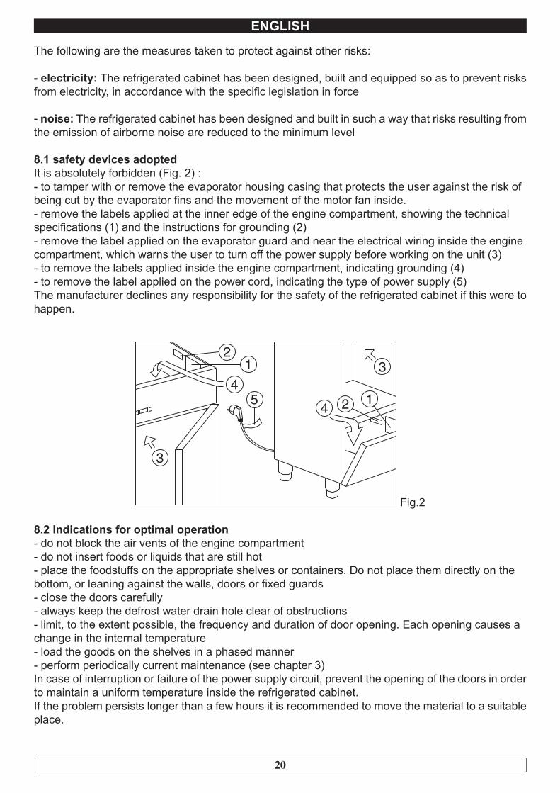
8.1 safety devices adoptedIt is absolutely forbidden (Fig. 2) :- to tamper with or remove the evaporator housing casing that protects the user against the risk ofbeing cut by the evaporator fins and the movement of the motor fan inside.- remove the labels applied at the inner edge of the engine compartment, showing the technicalspecifications (1) and the instructions for grounding (2)- remove the label applied on the evaporator guard and near the electrical wiring inside the enginecompartment, which warns the user to turn off the power supply before working on the unit (3)- to remove the labels applied inside the engine compartment, indicating grounding (4)- to remove the label applied on the power cord, indicating the type of power supply (5)The manufacturer declines any responsibility for the safety of the refrigerated cabinet if this were to happen.
12
3
34
5 4 2 1
Fig.2
8.2 Indications for optimal operation- do not block the air vents of the engine compartment- do not insert foods or liquids that are still hot- place the foodstuffs on the appropriate shelves or containers. Do not place them directly on thebottom, or leaning against the walls, doors or fixed guards- close the doors carefully- always keep the defrost water drain hole clear of obstructions- limit, to the extent possible, the frequency and duration of door opening. Each opening causes achange in the internal temperature- load the goods on the shelves in a phased manner- perform periodically current maintenance (see chapter 3)In case of interruption or failure of the power supply circuit, prevent the opening of the doors in order to maintain a uniform temperature inside the refrigerated cabinet.If the problem persists longer than a few hours it is recommended to move the material to a suitable place.
21
ENGLISH
CHAPTER 9 CONTROLS
9.1 Description of the controls and buttons (Fig. 3)
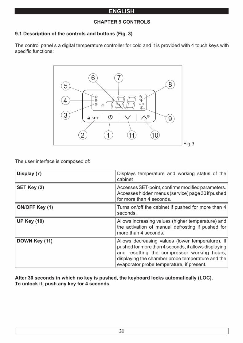
The control panel s a digital temperature controller for cold and it is provided with 4 touch keys with specific functions:
Fig.3
The user interface is composed of:
Display (7) Displays temperature and working status of the cabinet
SET Key (2) Accesses SET-point, confirms modified parameters. Accesses hidden menus (service) page 30 if pushed for more than 4 seconds.
ON/OFF Key (1) Turns on/off the cabinet if pushed for more than 4 seconds.
UP Key (10) Allows increasing values (higher temperature) and the activation of manual defrosting if pushed for more than 4 seconds.
DOWN Key (11) Allows decreasing values (lower temperature). If pushed for more than 4 seconds, it allows displaying and resetting the compressor working hours, displaying the chamber probe temperature and the evaporator probe temperature, if present.
After 30 seconds in which no key is pushed, the keyboard locks automatically (LOC). To unlock it, push any key for 4 seconds.
22
ENGLISH
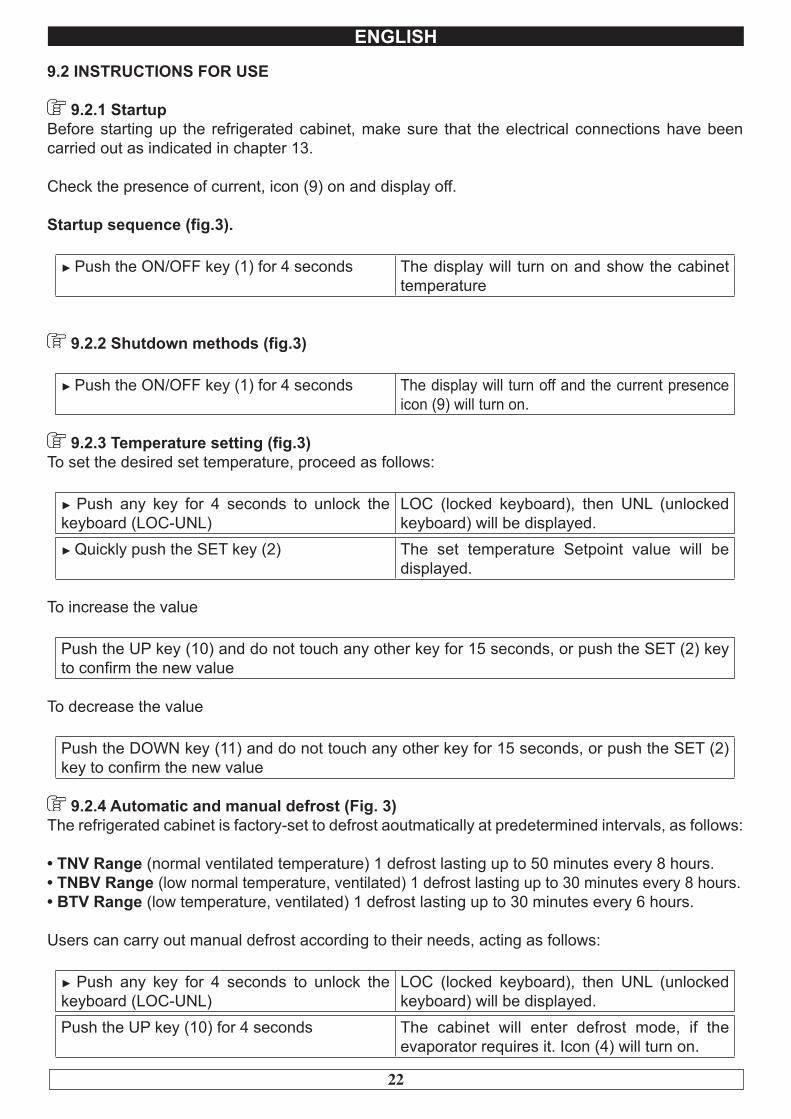
9.2 INSTRUCTIONS FOR USE
9.2.1 StartupBefore starting up the refrigerated cabinet, make sure that the electrical connections have been carried out as indicated in chapter 13.
Check the presence of current, icon (9) on and display off.
Startup sequence (fig.3).
► Push the ON/OFF key (1) for 4 seconds The display will turn on and show the cabinet temperature
9.2.2 Shutdown methods (fig.3)
► Push the ON/OFF key (1) for 4 seconds The display will turn off and the current presence icon (9) will turn on.
9.2.3 Temperature setting (fig.3)To set the desired set temperature, proceed as follows:
► Push any key for 4 seconds to unlock the keyboard (LOC-UNL)
LOC (locked keyboard), then UNL (unlocked keyboard) will be displayed.
► Quickly push the SET key (2) The set temperature Setpoint value will be displayed.
To increase the value
Push the UP key (10) and do not touch any other key for 15 seconds, or push the SET (2) key to confirm the new value
To decrease the value
Push the DOWN key (11) and do not touch any other key for 15 seconds, or push the SET (2) key to confirm the new value
9.2.4 Automatic and manual defrost (Fig. 3)The refrigerated cabinet is factory-set to defrost aoutmatically at predetermined intervals, as follows:
• TNV Range (normal ventilated temperature) 1 defrost lasting up to 50 minutes every 8 hours.• TNBV Range (low normal temperature, ventilated) 1 defrost lasting up to 30 minutes every 8 hours.• BTV Range (low temperature, ventilated) 1 defrost lasting up to 30 minutes every 6 hours.
Users can carry out manual defrost according to their needs, acting as follows:
► Push any key for 4 seconds to unlock the keyboard (LOC-UNL)
LOC (locked keyboard), then UNL (unlocked keyboard) will be displayed.
Push the UP key (10) for 4 seconds The cabinet will enter defrost mode, if the evaporator requires it. Icon (4) will turn on.
23
ENGLISH
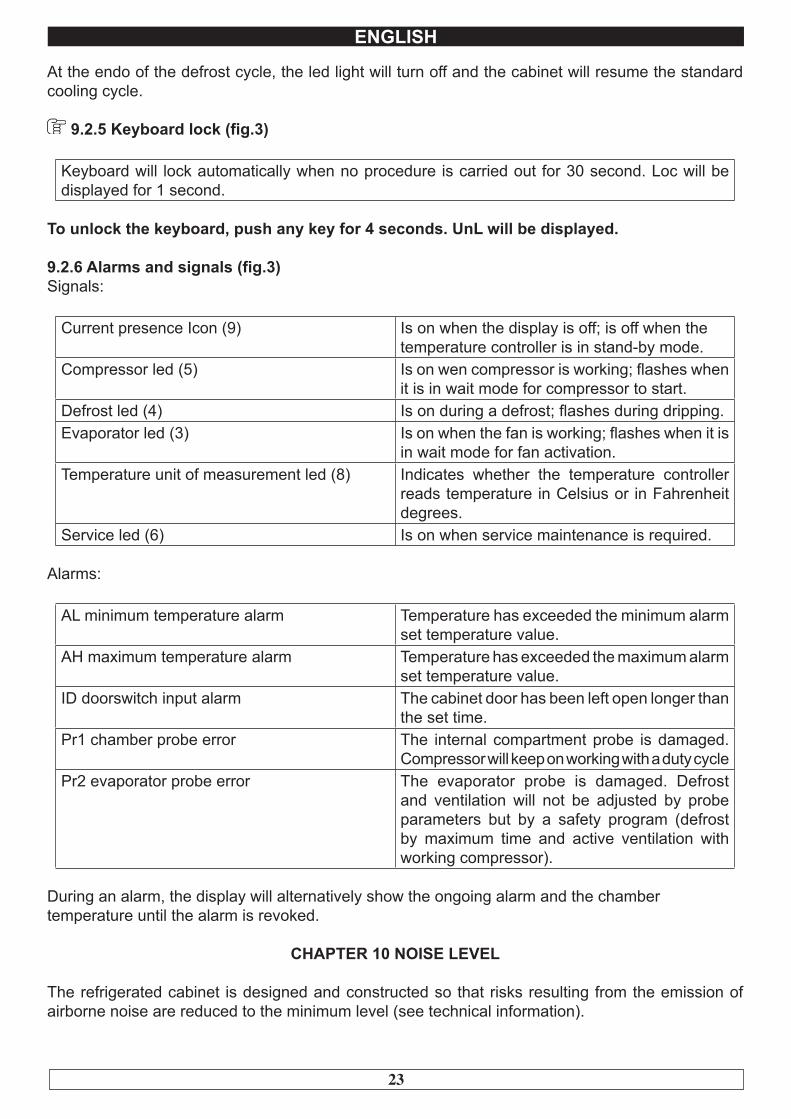
At the endo of the defrost cycle, the led light will turn off and the cabinet will resume the standard cooling cycle.
9.2.5 Keyboard lock (fig.3)
Keyboard will lock automatically when no procedure is carried out for 30 second. Loc will be displayed for 1 second.
To unlock the keyboard, push any key for 4 seconds. UnL will be displayed.
9.2.6 Alarms and signals (fig.3)Signals:
Current presence Icon (9) Is on when the display is off; is off when the temperature controller is in stand-by mode.
Compressor led (5) Is on wen compressor is working; flashes when it is in wait mode for compressor to start.
Defrost led (4) Is on during a defrost; flashes during dripping.Evaporator led (3) Is on when the fan is working; flashes when it is
in wait mode for fan activation.Temperature unit of measurement led (8) Indicates whether the temperature controller
reads temperature in Celsius or in Fahrenheit degrees.
Service led (6) Is on when service maintenance is required.
Alarms:
AL minimum temperature alarm Temperature has exceeded the minimum alarm set temperature value.
AH maximum temperature alarm Temperature has exceeded the maximum alarm set temperature value.
ID doorswitch input alarm The cabinet door has been left open longer than the set time.
Pr1 chamber probe error The internal compartment probe is damaged. Compressor will keep on working with a duty cycle
Pr2 evaporator probe error The evaporator probe is damaged. Defrost and ventilation will not be adjusted by probe parameters but by a safety program (defrost by maximum time and active ventilation with working compressor).
During an alarm, the display will alternatively show the ongoing alarm and the chamber temperature until the alarm is revoked.
CHAPTER 10 NOISE LEVEL
The refrigerated cabinet is designed and constructed so that risks resulting from the emission of airborne noise are reduced to the minimum level (see technical information).
24
ENGLISH
CHAPTER 11 MATERIALS AND FLUID USED
The materials in contact or which may come into contact with foodstuffs comply with the relevantdirectives.The refrigerated cabinet has been designed and built in such a way that these materials can becleaned before each use.The coolants used R404A/R290 conform to the relevant provisions of law (see Table 1).R404A is a fluorinated gas covered by the Kyoto Protocol with a GWP potential of 3300
For refrigerated cabinets containing R290: R290 (Propane) is a natural gas with noeffect on the environment but it is flammable and therefore contained in the system in minimumquantities prescribed by regulations on flammable gas and it is hermetically sealed.Before any intervention on the coolant system, carefully read the attached INSTRUCTIONSFOR REPAIRS ON UNITS WITH R290 COOLANT GAS (PROPANE) supplied with the use andmaintenance manual.
The symbol indicates that this product must not be treated as household waste.
To prevent potential negative consequences for the environment and human health, make sure that this product is properly disposed of and recycled.
For more information regarding the disposal and recycling of this product, please contact yourDistributor, after sale Service, or waste treatment Service.
CHAPTER 12 TRANSPORT AND HANDLING
The transport and handling of the refrigerated cabinet must only be done while maintaining the vertical position, observing the markings on the packaging.
The manufacturer disclaims any liability for problems resulting from transport performed underconditions other than those specified above.The accessories of the refrigerated cabinet (guides, grilles, trays) are packaged separately and placed inside the unit.
25
ENGLISH
The refrigerated cabinet is mounted on a wooden base with screws and packaged with polyethylene, carton, crate or boxes.
Regarding the disposal of the packaging it is necessary to refer to current regulations in your country.
The movement of the refrigerated cabinet shall be performed using a fork lift or pallet trucksequipped with suitable forks (length of at least 2/3 of the unit).The dimensions and masses of the refrigerated cabinets packed are shown in Table 1.The limits of stackability and the centre of gravity are indicated on the label of the package.
12.1 Positioning operationsSince the incorrect positioning of the refrigerated cabinet can cause damage to the same, jeopardizing its proper functioning and cause risks to the personnel, the installer must comply with the followinggeneral rules:- position the refrigerated cabinet keeping a minimum distance of 3 cm from any wall- the environment must be sufficiently ventilated- position the refrigerated cabinet away from heat sources- avoid exposure to direct sunlight- remove the polyethylene, cardboard or wood packaging
Polyethylene is dangerous for children
- remove any accessories with external connections
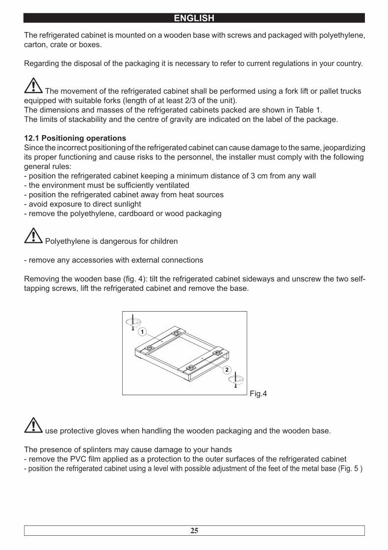
Removing the wooden base (fig. 4): tilt the refrigerated cabinet sideways and unscrew the two self-tapping screws, lift the refrigerated cabinet and remove the base.
Fig.4
use protective gloves when handling the wooden packaging and the wooden base.
The presence of splinters may cause damage to your hands- remove the PVC film applied as a protection to the outer surfaces of the refrigerated cabinet- position the refrigerated cabinet using a level with possible adjustment of the feet of the metal base (Fig. 5 )

26
ENGLISH
Fig.5
- position the grille holding guide fails in the holes of the racks (Fig. 6 )
Fig.6
- insert the grilles for food in the special guides- insert the condensate water drain pan into the special guide rails already fixed under the refrigerated cabinet if provided.
12.2 REM cabinets ( Fig. 7 )
Fig.7
- position the refrigerated cabinet as described above (Fig. 5)- prepare the two tubes that come out of the refrigerated cabinet (ø 6 mm outlet, ø 10 mm - ø 12 mm suction) for the connection to the respective pipes- connect the pipes of the condensing unit to the pipes of the refrigerated cabinet- create a vacuum and then carry out the loading of the coolant- make the electrical connection of the refrigerated cabinet to the condensing unit- perform a functional test to verify the correct gas charge.
CHAPTER 13 ELECTRICAL WIRING AND CONNECTIONS
The electrical system and connection must be carried out by qualified personnel. Before installation, measure the impedance of the network, the impedance value for the connection to the network must not exceed 0.075 ohm.
27
ENGLISH
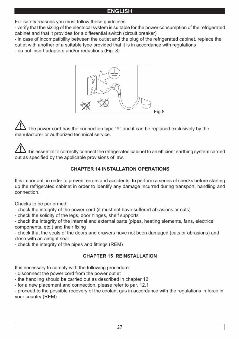
For safety reasons you must follow these guidelines:- verify that the sizing of the electrical system is suitable for the power consumption of the refrigerated cabinet and that it provides for a differential switch (circuit breaker)- in case of incompatibility between the outlet and the plug of the refrigerated cabinet, replace theoutlet with another of a suitable type provided that it is in accordance with regulations- do not insert adapters and/or reductions (Fig. 8)
Fig.8
The power cord has the connection type “Y” and it can be replaced exclusively by themanufacturer or authorized technical service.
It is essential to correctly connect the refrigerated cabinet to an efficient earthing system carried out as specified by the applicable provisions of law.
CHAPTER 14 INSTALLATION OPERATIONS
It is important, in order to prevent errors and accidents, to perform a series of checks before starting up the refrigerated cabinet in order to identify any damage incurred during transport, handling and connection.
Checks to be performed:- check the integrity of the power cord (it must not have suffered abrasions or cuts)- check the solidity of the legs, door hinges, shelf supports- check the integrity of the internal and external parts (pipes, heating elements, fans, electricalcomponents, etc.) and their fixing- check that the seals of the doors and drawers have not been damaged (cuts or abrasions) andclose with an airtight seal- check the integrity of the pipes and fittings (REM)
CHAPTER 15 REINSTALLATION
It is necessary to comply with the following procedure:- disconnect the power cord from the power outlet- the handling should be carried out as described in chapter 12- for a new placement and connection, please refer to par. 12.1- proceed to the possible recovery of the coolant gas in accordance with the regulations in force inyour country (REM)
28
ATTENZIONE!ISTRUZIONI RISERVATE A PERSONALE TECNICO AUTORIZZATO
Si avvisano gli utenti che qualsiasi intervento eseguito da personale non tecnico o non autorizzato produrrà la decadenza delle condizioni
di garanzia.
WARNING!INSTRUCTIONS STRICTLY RESERVED TO AUTHORIZED
TECHNICAL PERSONNEL
Every intervention executed by a non authorized technical personnelimplies a warranty decay.
29
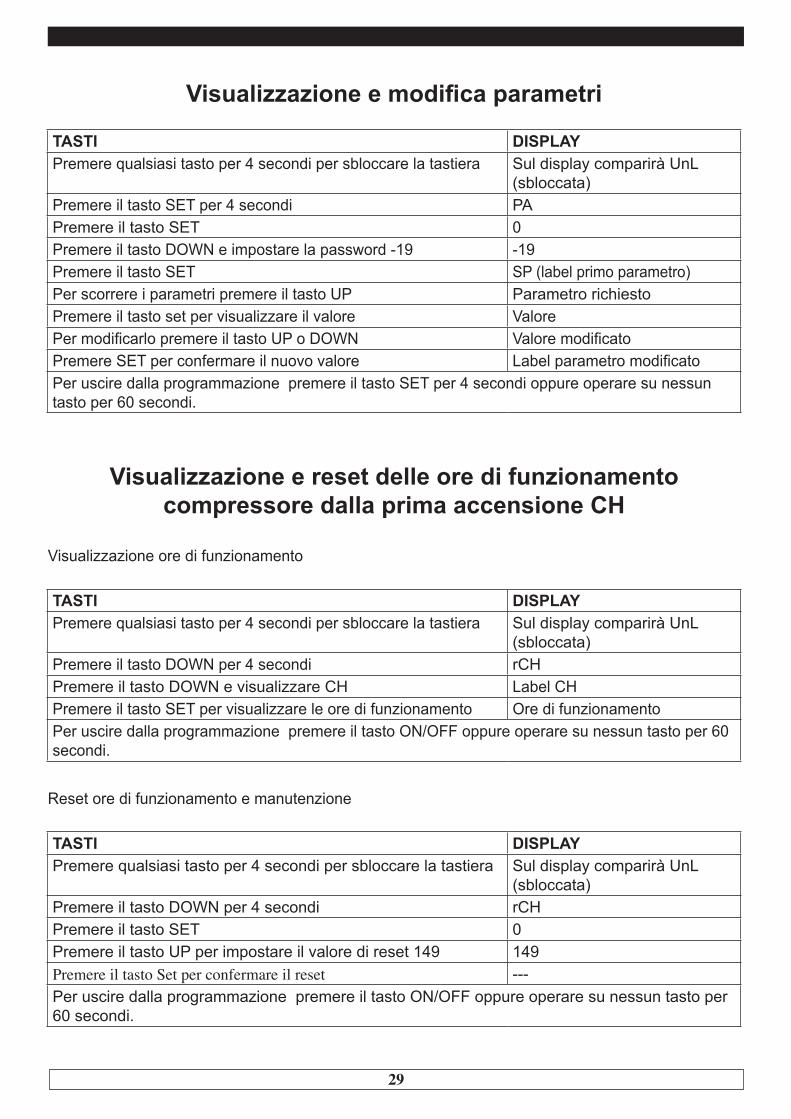
Visualizzazione e modifica parametri
TASTI DISPLAYPremere qualsiasi tasto per 4 secondi per sbloccare la tastiera Sul display comparirà UnL
(sbloccata)Premere il tasto SET per 4 secondi PAPremere il tasto SET 0Premere il tasto DOWN e impostare la password -19 -19Premere il tasto SET SP (label primo parametro)Per scorrere i parametri premere il tasto UP Parametro richiestoPremere il tasto set per visualizzare il valore ValorePer modificarlo premere il tasto UP o DOWN Valore modificatoPremere SET per confermare il nuovo valore Label parametro modificatoPer uscire dalla programmazione premere il tasto SET per 4 secondi oppure operare su nessun tasto per 60 secondi.
Visualizzazione e reset delle ore di funzionamento compressore dalla prima accensione CH
Visualizzazione ore di funzionamento
TASTI DISPLAYPremere qualsiasi tasto per 4 secondi per sbloccare la tastiera Sul display comparirà UnL
(sbloccata)Premere il tasto DOWN per 4 secondi rCHPremere il tasto DOWN e visualizzare CH Label CHPremere il tasto SET per visualizzare le ore di funzionamento Ore di funzionamentoPer uscire dalla programmazione premere il tasto ON/OFF oppure operare su nessun tasto per 60 secondi.
Reset ore di funzionamento e manutenzione
TASTI DISPLAYPremere qualsiasi tasto per 4 secondi per sbloccare la tastiera Sul display comparirà UnL
(sbloccata)Premere il tasto DOWN per 4 secondi rCHPremere il tasto SET 0Premere il tasto UP per impostare il valore di reset 149 149Premere il tasto Set per confermare il reset ---Per uscire dalla programmazione premere il tasto ON/OFF oppure operare su nessun tasto per 60 secondi.
30
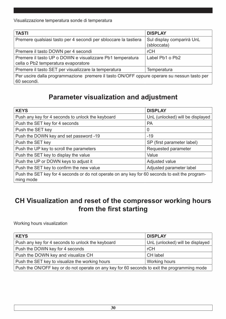
Visualizzazione temperatura sonde di temperatura
TASTI DISPLAYPremere qualsiasi tasto per 4 secondi per sbloccare la tastiera Sul display comparirà UnL
(sbloccata)Premere il tasto DOWN per 4 secondi rCHPremere il tasto UP o DOWN e visualizzare Pb1 temperatura cella o Pb2 temperatura evaporatore
Label Pb1 o Pb2
Premere il tasto SET per visualizzare la temperatura TemperaturaPer uscire dalla programmazione premere il tasto ON/OFF oppure operare su nessun tasto per 60 secondi.
Parameter visualization and adjustment
KEYS DISPLAYPush any key for 4 seconds to unlock the keyboard UnL (unlocked) will be displayedPush the SET key for 4 seconds PAPush the SET key 0Push the DOWN key and set password -19 -19Push the SET key SP (first parameter label)Push the UP key to scroll the parameters Requested parameterPush the SET key to display the value ValuePush the UP or DOWN keys to adjust it Adjusted value Push the SET key to confirm the new value Adjusted parameter labelPush the SET key for 4 seconds or do not operate on any key for 60 seconds to exit the program-ming mode
CH Visualization and reset of the compressor working hours from the first starting
Working hours visualization
KEYS DISPLAYPush any key for 4 seconds to unlock the keyboard UnL (unlocked) will be displayedPush the DOWN key for 4 seconds rCHPush the DOWN key and visualize CH CH labelPush the SET key to visualize the working hours Working hoursPush the ON/OFF key or do not operate on any key for 60 seconds to exit the programming mode
31
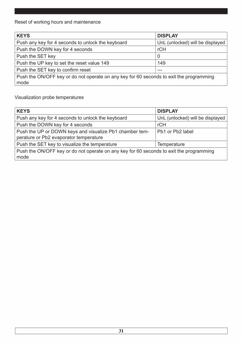
Reset of working hours and maintenance
KEYS DISPLAYPush any key for 4 seconds to unlock the keyboard UnL (unlocked) will be displayedPush the DOWN key for 4 seconds rCHPush the SET key 0Push the UP key to set the reset value 149 149Push the SET key to confirm reset --- Push the ON/OFF key or do not operate on any key for 60 seconds to exit the programming mode
Visualization probe temperatures
KEYS DISPLAYPush any key for 4 seconds to unlock the keyboard UnL (unlocked) will be displayedPush the DOWN key for 4 seconds rCHPush the UP or DOWN keys and visualize Pb1 chamber tem-perature or Pb2 evaporator temperature
Pb1 or Pb2 label
Push the SET key to visualize the temperature TemperaturePush the ON/OFF key or do not operate on any key for 60 seconds to exit the programming mode
32
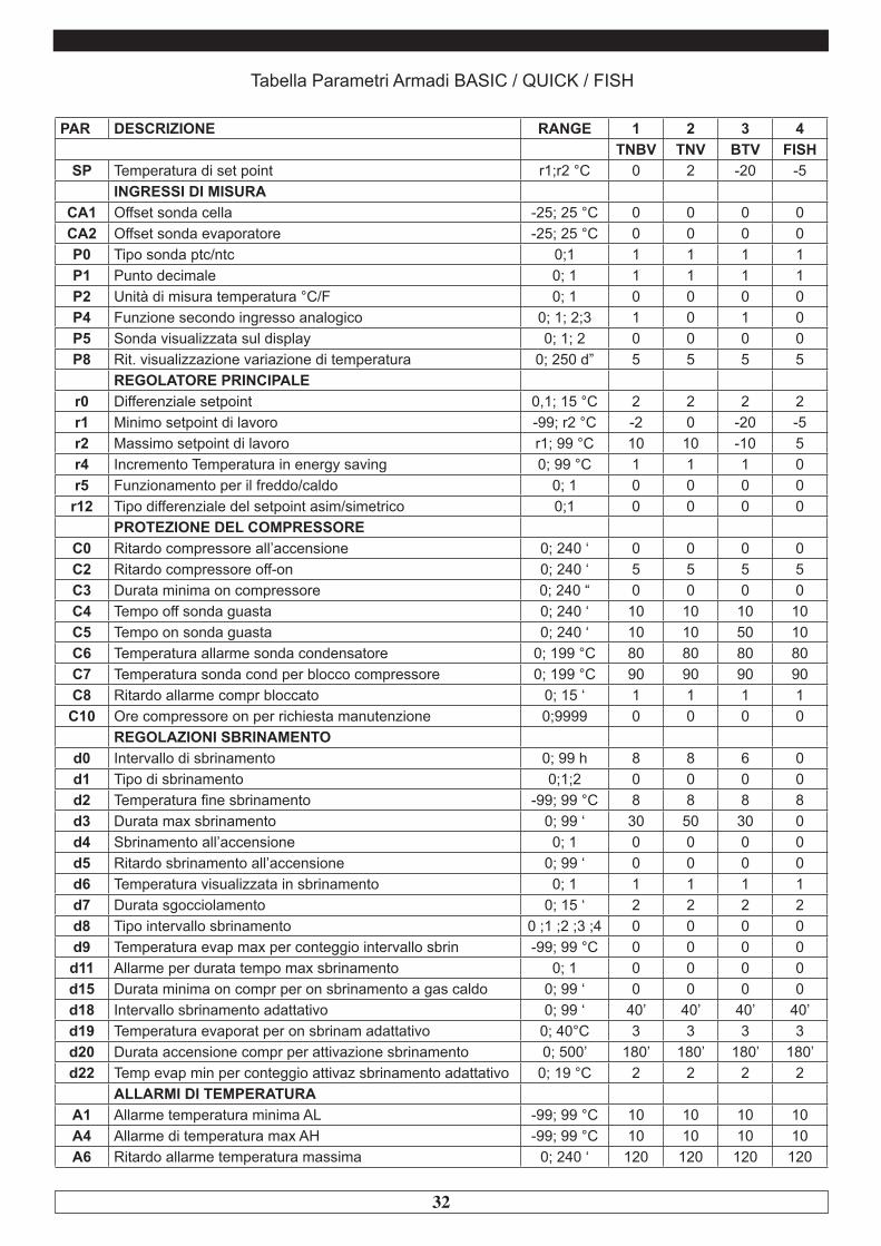
Tabella Parametri Armadi BASIC / QUICK / FISH
PAR DESCRIZIONE RANGE 1 2 3 4TNBV TNV BTV FISH
SP Temperatura di set point r1;r2 °C 0 2 -20 -5INGRESSI DI MISURA
CA1 Offset sonda cella -25; 25 °C 0 0 0 0CA2 Offset sonda evaporatore -25; 25 °C 0 0 0 0P0 Tipo sonda ptc/ntc 0;1 1 1 1 1P1 Punto decimale 0; 1 1 1 1 1P2 Unità di misura temperatura °C/F 0; 1 0 0 0 0P4 Funzione secondo ingresso analogico 0; 1; 2;3 1 0 1 0P5 Sonda visualizzata sul display 0; 1; 2 0 0 0 0P8 Rit. visualizzazione variazione di temperatura 0; 250 d” 5 5 5 5
REGOLATORE PRINCIPALEr0 Differenziale setpoint 0,1; 15 °C 2 2 2 2r1 Minimo setpoint di lavoro -99; r2 °C -2 0 -20 -5r2 Massimo setpoint di lavoro r1; 99 °C 10 10 -10 5r4 Incremento Temperatura in energy saving 0; 99 °C 1 1 1 0r5 Funzionamento per il freddo/caldo 0; 1 0 0 0 0
r12 Tipo differenziale del setpoint asim/simetrico 0;1 0 0 0 0PROTEZIONE DEL COMPRESSORE
C0 Ritardo compressore all’accensione 0; 240 ‘ 0 0 0 0C2 Ritardo compressore off-on 0; 240 ‘ 5 5 5 5C3 Durata minima on compressore 0; 240 “ 0 0 0 0C4 Tempo off sonda guasta 0; 240 ‘ 10 10 10 10C5 Tempo on sonda guasta 0; 240 ‘ 10 10 50 10C6 Temperatura allarme sonda condensatore 0; 199 °C 80 80 80 80C7 Temperatura sonda cond per blocco compressore 0; 199 °C 90 90 90 90C8 Ritardo allarme compr bloccato 0; 15 ‘ 1 1 1 1C10 Ore compressore on per richiesta manutenzione 0;9999 0 0 0 0
REGOLAZIONI SBRINAMENTOd0 Intervallo di sbrinamento 0; 99 h 8 8 6 0d1 Tipo di sbrinamento 0;1;2 0 0 0 0d2 Temperatura fine sbrinamento -99; 99 °C 8 8 8 8d3 Durata max sbrinamento 0; 99 ‘ 30 50 30 0d4 Sbrinamento all’accensione 0; 1 0 0 0 0d5 Ritardo sbrinamento all’accensione 0; 99 ‘ 0 0 0 0d6 Temperatura visualizzata in sbrinamento 0; 1 1 1 1 1d7 Durata sgocciolamento 0; 15 ‘ 2 2 2 2d8 Tipo intervallo sbrinamento 0 ;1 ;2 ;3 ;4 0 0 0 0d9 Temperatura evap max per conteggio intervallo sbrin -99; 99 °C 0 0 0 0d11 Allarme per durata tempo max sbrinamento 0; 1 0 0 0 0d15 Durata minima on compr per on sbrinamento a gas caldo 0; 99 ‘ 0 0 0 0d18 Intervallo sbrinamento adattativo 0; 99 ‘ 40’ 40’ 40’ 40’d19 Temperatura evaporat per on sbrinam adattativo 0; 40°C 3 3 3 3d20 Durata accensione compr per attivazione sbrinamento 0; 500’ 180’ 180’ 180’ 180’d22 Temp evap min per conteggio attivaz sbrinamento adattativo 0; 19 °C 2 2 2 2
ALLARMI DI TEMPERATURAA1 Allarme temperatura minima AL -99; 99 °C 10 10 10 10A4 Allarme di temperatura max AH -99; 99 °C 10 10 10 10A6 Ritardo allarme temperatura massima 0; 240 ‘ 120 120 120 120

33
A7 Ritardo allarme temperatura minima 0; 240 ‘ 30 30 30 30A8 Ritardo allarme temperatura per termine sbrin. 0; 240 ‘ 60 60 60 60A9 Ritardo allarme temperatura per micro porta off 0; 240 ‘ 60 60 60 60A11 Differenziale parametri allarme 0; 15 °C 2 2 2 2
VENTILATORE EVAPORATOREF0 Ventola evap on 0;1;2;3;4 4 2 4 2F1 Temperatura evaporatore -99; 99 °C 4 4 40 4F2 Ventilatori in sbrinamento 0; 1; 2 0 1 0 1F3 Tempo ritardo ventilatori 0; 15 ‘ 2 2 2 2F4 Durata OFF ventilatore per energy saving 0; 240 “ 0 0 0 0F5 Durata ON ventilatore per energy saving 0; 240 “ 1 1 1 1F7 Durata spegnimento vent quando compr OFF 0;240” 0 0 0 0F8 Durata accensione vent quando compr OFF 0;240” 0 0 0 0F9 Ritardo spegnimento ventilatore per comp OFF 0; 240 “ 0 0 0 0
INGRESSI DIGITALIi0 On off micro porta 0;…;5 2 2 2 0i1 Contatto micro porta NA-NC 0; 1 0 0 0 0i2 Ritardo allarme microporta on -1; 120 ‘ 30 30 30 30i3 Durata max attivazione micro -1; 120 ‘ 15 15 15 15
i10 Tempo per reset micro per attivazione Energy Saving 0; 999 ‘ 180 180 180 180i13 Numero attivazioni microporta per on sbrinamento 0; 240’ 0’ 0’ 0’ 0’i14 Durata min attivazione ing microporta per on sbrinamen. 0; 240’ 0’ 0’ 0’ 0’
ENERGY SAVING IN TEMPO REALEHE2 Durata MASSIMA attivazione Energy Saving 0; 999’ 0 0 0 0HE3 Attivazione basso consumo per assenza di operazioni 0; 240’ 0 0 0 0
VARIEPOF Attivazione tasto On/Off 0; 1 1 1 1 1PAS Password di accesso parametri -99; 999 -19 -19 -19 -19
Rev.05/2017
34
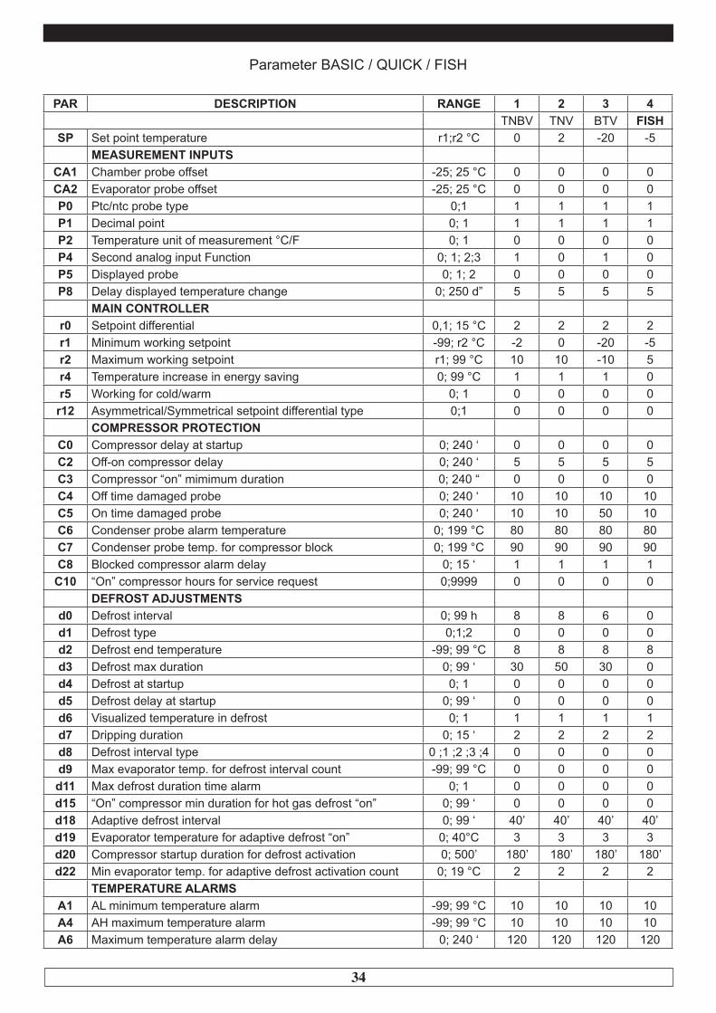
Parameter BASIC / QUICK / FISH
PAR DESCRIPTION RANGE 1 2 3 4TNBV TNV BTV FISH
SP Set point temperature r1;r2 °C 0 2 -20 -5MEASUREMENT INPUTS
CA1 Chamber probe offset -25; 25 °C 0 0 0 0CA2 Evaporator probe offset -25; 25 °C 0 0 0 0P0 Ptc/ntc probe type 0;1 1 1 1 1P1 Decimal point 0; 1 1 1 1 1P2 Temperature unit of measurement °C/F 0; 1 0 0 0 0P4 Second analog input Function 0; 1; 2;3 1 0 1 0P5 Displayed probe 0; 1; 2 0 0 0 0P8 Delay displayed temperature change 0; 250 d” 5 5 5 5
MAIN CONTROLLERr0 Setpoint differential 0,1; 15 °C 2 2 2 2r1 Minimum working setpoint -99; r2 °C -2 0 -20 -5r2 Maximum working setpoint r1; 99 °C 10 10 -10 5r4 Temperature increase in energy saving 0; 99 °C 1 1 1 0r5 Working for cold/warm 0; 1 0 0 0 0
r12 Asymmetrical/Symmetrical setpoint differential type 0;1 0 0 0 0COMPRESSOR PROTECTION
C0 Compressor delay at startup 0; 240 ‘ 0 0 0 0C2 Off-on compressor delay 0; 240 ‘ 5 5 5 5C3 Compressor “on” mimimum duration 0; 240 “ 0 0 0 0C4 Off time damaged probe 0; 240 ‘ 10 10 10 10C5 On time damaged probe 0; 240 ‘ 10 10 50 10C6 Condenser probe alarm temperature 0; 199 °C 80 80 80 80C7 Condenser probe temp. for compressor block 0; 199 °C 90 90 90 90C8 Blocked compressor alarm delay 0; 15 ‘ 1 1 1 1C10 “On” compressor hours for service request 0;9999 0 0 0 0
DEFROST ADJUSTMENTSd0 Defrost interval 0; 99 h 8 8 6 0d1 Defrost type 0;1;2 0 0 0 0d2 Defrost end temperature -99; 99 °C 8 8 8 8d3 Defrost max duration 0; 99 ‘ 30 50 30 0d4 Defrost at startup 0; 1 0 0 0 0d5 Defrost delay at startup 0; 99 ‘ 0 0 0 0d6 Visualized temperature in defrost 0; 1 1 1 1 1d7 Dripping duration 0; 15 ‘ 2 2 2 2d8 Defrost interval type 0 ;1 ;2 ;3 ;4 0 0 0 0d9 Max evaporator temp. for defrost interval count -99; 99 °C 0 0 0 0d11 Max defrost duration time alarm 0; 1 0 0 0 0d15 “On” compressor min duration for hot gas defrost “on” 0; 99 ‘ 0 0 0 0d18 Adaptive defrost interval 0; 99 ‘ 40’ 40’ 40’ 40’d19 Evaporator temperature for adaptive defrost “on” 0; 40°C 3 3 3 3d20 Compressor startup duration for defrost activation 0; 500’ 180’ 180’ 180’ 180’d22 Min evaporator temp. for adaptive defrost activation count 0; 19 °C 2 2 2 2
TEMPERATURE ALARMSA1 AL minimum temperature alarm -99; 99 °C 10 10 10 10A4 AH maximum temperature alarm -99; 99 °C 10 10 10 10A6 Maximum temperature alarm delay 0; 240 ‘ 120 120 120 120

35
A7 Minimum temperature alarm delay 0; 240 ‘ 30 30 30 30A8 Temperature alarm delay for defrost end 0; 240 ‘ 60 60 60 60A9 Temperature alarm delay for doorswitch “off” 0; 240 ‘ 60 60 60 60A11 Alarm parameter differential 0; 15 °C 2 2 2 2
EVAPORATOR FANF0 Evaporator fan on 0;1;2;3;4 4 2 4 2F1 Evaporator temperature -99; 99 °C 4 4 40 4F2 Fans in defrost 0; 1; 2 0 1 0 1F3 Fan delay time 0; 15 ‘ 2 2 2 2F4 Fan OFF duration for energy saving 0; 240 “ 0 0 0 0F5 ON fan duration for energy saving 0; 240 “ 1 1 1 1F7 Fan shutdown duration when compressor OFF 0;240” 0 0 0 0F8 Fan startup duration when compressor OFF 0;240” 0 0 0 0F9 Fan shutdown delay for compressor OFF 0; 240 “ 0 0 0 0
DIGITAL INPUTSi0 On off doorswitch 0;…;5 2 2 2 0i1 NA-NC doorswitch contact 0; 1 0 0 0 0i2 Doorswitch alarm delay on -1; 120 ‘ 30 30 30 30i3 Doorswitch activation maximum duration -1; 120 ‘ 15 15 15 15
i10 Time for doorswitch reset for Energy Saving activation 0; 999 ‘ 180 180 180 180i13 Number doorswitch activations for defrost “on” 0; 240’ 0’ 0’ 0’ 0’i14 Doorswitch input activation Minimum duration for defrost “on” 0; 240’ 0’ 0’ 0’ 0’
REAL TIME ENERGY SAVINGHE2 Energy Saving activation MAXIMUM duration 0; 999’ 0 0 0 0HE3 Low consumption activation for lack of operations 0; 240’ 0 0 0 0
GENERAL POF On/Off key activation 0; 1 1 1 1 1PAS Parameter access password -99; 999 -19 -19 -19 -19
Rev.05/2017
36
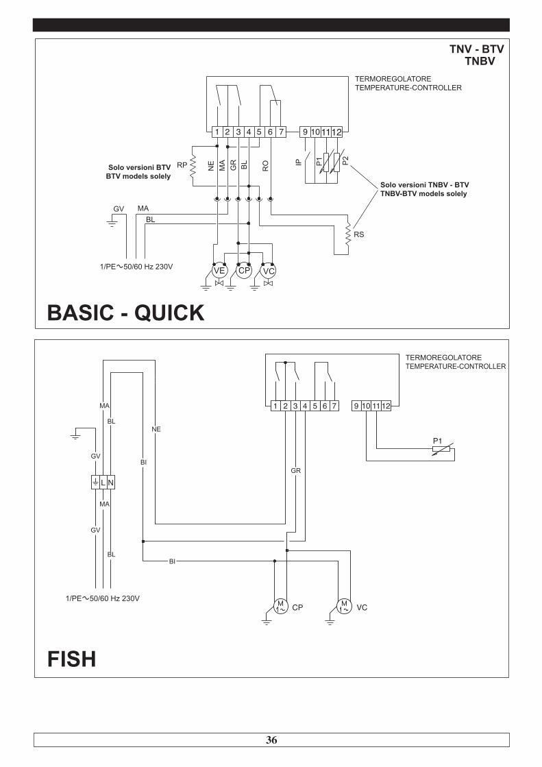
TNBV
P1 P2
GV
TERMOREGOLATORETEMPERATURE-CONTROLLER
Solo versioni BTVBTV models solely
BASIC - QUICK
NL
VC
P1
GR
CP
NEBL
MA
GV
BI
MA
GV
BL
BI
1110 1232 4 51 6 7 9
FISH
TERMOREGOLATORETEMPERATURE-CONTROLLER
Solo versioni TNBV - BTVTNBV-BTV models solely

37
Legenda componentiCP - Moto-compressoreK1 - Relè compressoreLI - Luce internaMS - Morsettiera alimentazioneRB - Resistenza bacinellaRC - Resistenza scaricoRS - Resistenza sbrinamentoIP - Interruttore portaRP - Resistenza anticondensaP1 - Sonda termostatoP2 - Sonda evaporatoreSG - Valvola solenoideVC - Ventilatore condensatoreVE - Ventilatore evaporatoreUR - Unità remota
Legenda coloriNE - NeroGR - GrigioAR - ArancioRO - RossoMA - MarroneBL - BluBI - BiancoGV - Giallo VerdeRA - RosaVI - ViolaAZ - Azzurro chiaro
Components keyCP - Moto-compressorK1 - Compressor relayLI - Internal lightMS - Power supply terminalRB - Basin heaterRC - Drain heaterRS - Defrost heaterIP - Door switchRP - Anti-condensate heaterP1 - Thermostat probeP2 - Evaporator probeSG - Solenoid ValveVC - Condenser fanVE - Evaporator fanUR - Remote unit
Colour KeyNE - BlackGR - GreyAR - OrangeRO - RedMA - BrownBL - BlueBI - WhiteGV - Yellow GreenRA - PinkVI - PurpleAZ - Light blue
38
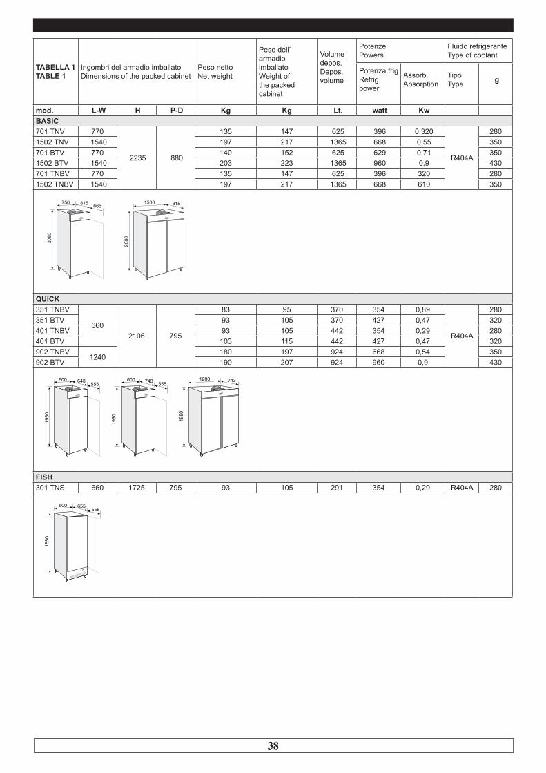
TABELLA 1 TABLE 1
Ingombri del armadio imballatoDimensions of the packed cabinet
Peso nettoNet weight
Peso dell’armadio imballatoWeight ofthe packedcabinet
Volume depos. Depos.volume
Potenze Powers
Fluido refrigerante Type of coolant
Potenza frig. Refrig. power
Assorb. Absorption
Tipo Type g
mod. L-W H P-D Kg Kg Lt. watt KwBASIC701 TNV 770
2235 880
135 147 625 396 0,320
R404A
2801502 TNV 1540 197 217 1365 668 0,55 350701 BTV 770 140 152 625 629 0,71 3501502 BTV 1540 203 223 1365 960 0,9 430701 TNBV 770 135 147 625 396 320 2801502 TNBV 1540 197 217 1365 668 610 350
QUICK351 TNBV
6602106 795
83 95 370 354 0,89
R404A
280351 BTV 93 105 370 427 0,47 320401 TNBV 93 105 442 354 0,29 280401 BTV 103 115 442 427 0,47 320902 TNBV
1240180 197 924 668 0,54 350
902 BTV 190 207 924 960 0,9 430
FISH301 TNS 660 1725 795 93 105 291 354 0,29 R404A 280
815750
2080
665 1500
2080
815
655600
1550
555
643600
1950
555 743600
1950
5551200
1950
743

39
EVERLASTING s.r.l.46029 SUZZARA (MN) - ITALY - S.S. Cisa km.161 Tel.0376/521800 (4 linee r.a.) - Telefax 0376/521794http://www.everlasting.it - E-mail:[email protected]
CODICE - CODE AEC IEE VN VNRef VNFrz GAS R404a GAS R290 TEMP
Kwh/Anno-Year Lt Lt Lt Kg Kg °C
Impiego previsto: Conservazione / Intended Use: StorageCategoria: Verticale / Category: VerticalAlte prestazioni, CLASSE CLIMATICA 5 (40°C, 40% UR) / Heavy-Duty CLIMATE CLASS 5 (40°C, 40% RH)Fluido refrigerante: R404a - GWP:3922 / Refrigerant fluid: R404a - GWP:3922Fluido refrigerante: R290 - GWP:3 / Refrigerant fluid: R290 - GWP:3 Legenda:AEC Kwh / Anno-Year: Consumo di energia annuo / Annual energy consumptionIEE: Indice di efficienza energetica / Energy efficiency indexVN: Volume netto dell’apparecchio / Net volume of the applianceVNRef: Volume di refrigerazione / Chilled volumeVNFrz: Volume di congelamento / Frozen volumeGAS Kg: Carica di fluido refrigerante / Refrigerant charge
CODICE - CODE AEC IEE VN VNRef VNFrz GAS R404a GAS R290 TEMP
Kwh/Anno-Year Lt Lt Lt Kg Kg °C
Impiego previsto: Conservazione / Intended Use: StorageCategoria: Verticale / Category: VerticalCLASSE CLIMATICA 4 (30°C, 55% UR) / CLIMATE CLASS 4 (30°C, 55% RH)Fluido refrigerante: R404a - GWP:3922 / Refrigerant fluid: R404a - GWP:3922Fluido refrigerante: R290 - GWP:3 / Refrigerant fluid: R290 - GWP:3 Legenda:AEC Kwh / Anno-Year: Consumo di energia annuo / Annual energy consumptionIEE: Indice di efficienza energetica / Energy efficiency indexVN: Volume netto dell’apparecchio / Net volume of the applianceVNRef: Volume di refrigerazione / Chilled volumeVNFrz: Volume di congelamento / Frozen volumeGAS Kg: Carica di fluido refrigerante / Refrigerant charge
BASICAC6011 463 33,04 B 482,3 482,3 / 0,28 / 0° +10°CAD6011 463 33,04 B 482,3 482,3 / 0,28 / -2° +10°CAE6011 3144 81,69 E 482,3 / 482,3 0,35 / -10° -20°CAC6022 1088 43,29 C 1159,5 1159,5 / 0,35 / 0° +10°CAD6022 1088 43,29 C 1159,5 1159,5 / 0,35 / -2° +10°CAE6022 4639 64,55 D 1159,5 / 1159,5 0,43 / -10° -20°C
QUICKAD1562 427 40,16 C 276,5 276,5 / 0,28 / -2° +10°CAF1562 2048 72,24 D 276,5 / 276,5 0,32 / -10° -20°CAD1572 496 42,81 C 334,1 334,1 / 0,28 / -2° +10°CAF1572 6107 71,48 D 334,1 / 334,1 0,32 / -10° -20°CAD1582 995 54,29 D 744,5 744,5 / 0,35 / -2° +10°CAF1582 3727 72,50 D 744,5 / 744,5 0,43 / -10° -20°C