Armada Technologies Pro900 Advanced Underground Locator ... · Armada Technologies Pro900 Advanced...
14
Armada Technologies Pro900 Advanced Underground Locator USER GUIDE WARNING – Read and understand the instructions before operating this unit. Failure to do so could lead to injury or death. The Armada Technologies Pro900 Advanced Underground Locator is designed to track underground wiring and find lost sprinkler valves. In addition, broken or severely damaged wires may also be located. The complete Pro900 kit consists of: (1) Pro900R Receiving Wand (1) Pro900T Transmitter and Carrying Case (1) ProH1 Headset (1) AC Wall Power Unit (1) IC2 Inductive Clamp (1) ProGS Ground Stake (1) Set of Black/Red Connecting Leads (1) Operating Manual Please be sure that all items are included before operating.
-
Upload
duongkhuong -
Category
Documents
-
view
218 -
download
2
Transcript of Armada Technologies Pro900 Advanced Underground Locator ... · Armada Technologies Pro900 Advanced...

Armada Technologies Pro900 Advanced Underground Locator
USER GUIDE
WARNING – Read and understand the instructions before operating this unit. Failure to do so could lead to injury or death.
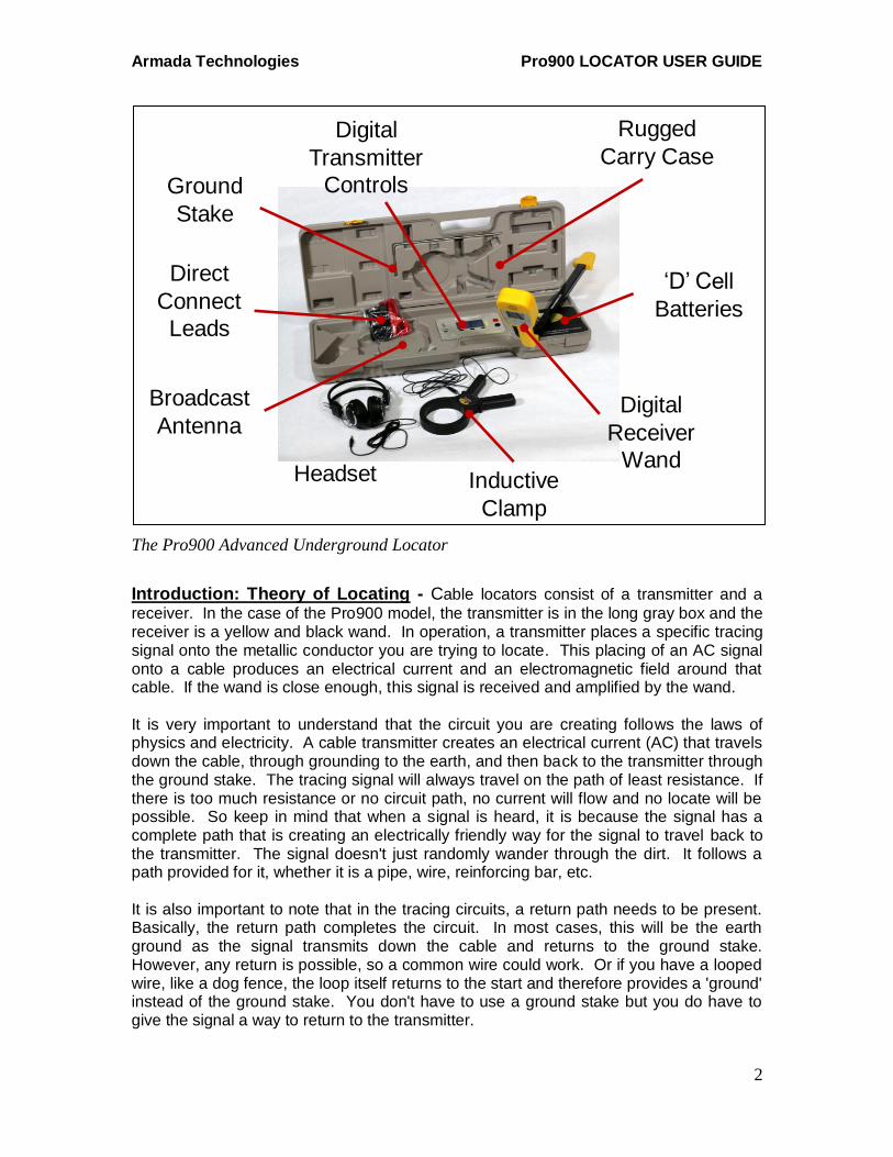
The Armada Technologies Pro900 Advanced Underground Locator is designed to track underground wiring and find lost sprinkler valves. In addition, broken or severely damaged wires may also be located. The complete Pro900 kit consists of:
(1) Pro900R Receiving Wand
(1) Pro900T Transmitter and Carrying Case
(1) ProH1 Headset
(1) AC Wall Power Unit
(1) IC2 Inductive Clamp
(1) ProGS Ground Stake
(1) Set of Black/Red Connecting Leads
(1) Operating Manual
Please be sure that all items are included before operating.
Armada Technologies Pro900 LOCATOR USER GUIDE
2
The Pro900 Advanced Underground Locator
Introduction: Theory of Locating - Cable locators consist of a transmitter and a
receiver. In the case of the Pro900 model, the transmitter is in the long gray box and the receiver is a yellow and black wand. In operation, a transmitter places a specific tracing signal onto the metallic conductor you are trying to locate. This placing of an AC signal onto a cable produces an electrical current and an electromagnetic field around that cable. If the wand is close enough, this signal is received and amplified by the wand. It is very important to understand that the circuit you are creating follows the laws of physics and electricity. A cable transmitter creates an electrical current (AC) that travels down the cable, through grounding to the earth, and then back to the transmitter through the ground stake. The tracing signal will always travel on the path of least resistance. If there is too much resistance or no circuit path, no current will flow and no locate will be possible. So keep in mind that when a signal is heard, it is because the signal has a complete path that is creating an electrically friendly way for the signal to travel back to the transmitter. The signal doesn't just randomly wander through the dirt. It follows a path provided for it, whether it is a pipe, wire, reinforcing bar, etc. It is also important to note that in the tracing circuits, a return path needs to be present. Basically, the return path completes the circuit. In most cases, this will be the earth ground as the signal transmits down the cable and returns to the ground stake. However, any return is possible, so a common wire could work. Or if you have a looped wire, like a dog fence, the loop itself returns to the start and therefore provides a 'ground' instead of the ground stake. You don't have to use a ground stake but you do have to give the signal a way to return to the transmitter.
‘D’ Cell
Batteries
Digital
Receiver
WandHeadset
Broadcast
Antenna
Inductive
Clamp
Ground
Stake
Digital
Transmitter
Controls
Rugged
Carry Case
Direct
Connect
Leads
Armada Technologies Pro900 LOCATOR USER GUIDE
3
Power – The Pro900 has two options for powering the transmitter; AC mains power or internal batteries. The AC adapter is useful when 120 Vac power outlets are available nearby. The adapter provides constant power and does not diminish batteries. To use the AC adapter, simply insert the round plug of the adapter into the “12 V” external power receptacle on the transmitter panel and the traditional bladed end into a wall outlet. The transmitter is then powered by AC mains voltage instead of batteries. The Pro900 transmitter also can use 8 “D” (LR20) alkaline batteries that are installed inside the transmitter battery compartment. Remove the battery compartment cover and install the batteries, paying particular attention to the positive and negative poles. A 9-volt square (6LR61) alkaline battery is needed for the Pro900 receiver. To install this battery, remove the battery compartment cover located on the back top portion of the Pro900 receiver. Install the 9 volt battery by connecting it to the battery snap boot inside the battery compartment. Don't yank or pull hard on the battery boot. Finally, replace the battery cover. To test that the batteries have been correctly installed, turn each unit on. The control panel LCDs will come on if the batteries have been connected correctly. If not, repeat the installation procedures. The battery compartment is designed to hold the batteries tightly so if you do not get a signal for power, try adjusting the batteries by rolling them or moving them forward and backward until the power does come on.
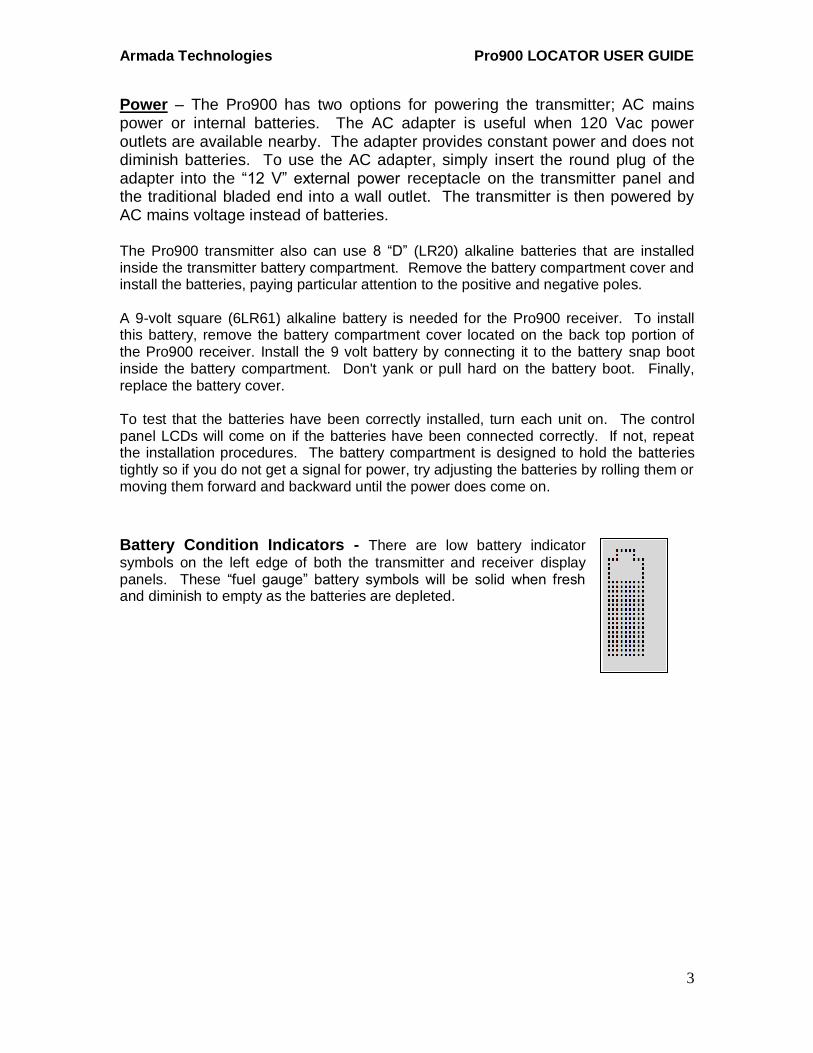
Battery Condition Indicators - There are low battery indicator
symbols on the left edge of both the transmitter and receiver display panels. These “fuel gauge” battery symbols will be solid when fresh and diminish to empty as the batteries are depleted.
Armada Technologies Pro900 LOCATOR USER GUIDE
4
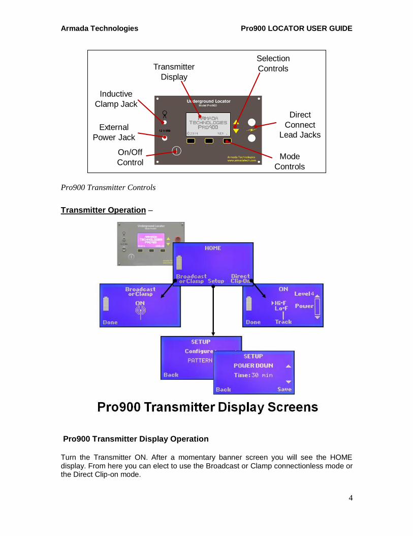
Pro900 Transmitter Controls
Transmitter Operation –
Pro900 Transmitter Display Operation Turn the Transmitter ON. After a momentary banner screen you will see the HOME display. From here you can elect to use the Broadcast or Clamp connectionless mode or the Direct Clip-on mode.
Mode
Controls
Selection
Controls
Direct
Connect
Lead Jacks
On/Off
Control
External
Power Jack
Inductive
Clamp Jack
Transmitter
Display
Armada Technologies Pro900 LOCATOR USER GUIDE
5
DIRECT CLIP-ON: Be sure that any equipment such as irrigation controllers, lighting
transformers or telecom equipment are disconnected from wires that are to be traced by direct connection. The output voltage on the Direct Connect leads can be in the hundreds of volts. Before selecting Direct Clip-on connect the red alligator lead to the wire you want to trace (target wire) and the black alligator lead to the included ground stake. Insert the ground stake into the soil or earth ground perpendicular to the path of the wire and as far from the transmitter as possible. Do not use common grounds such as pipes or electrical grounds unless you have no choice. An independent ground stake usually works better than a common ground. Select Direct Clip-on, which turns on the transmitter output at the lead jacks. Adjust the power output selector arrows to increase the power to a visible level on the bar graph. As a rule it is best to start tracing with a low level signal indicated by an “OK” near the power output bar. If you can’t achieve the minimum “OK” indication, turn the unit off and retry your grounding operation above. A good ground is crucial for optimum
operation. Soil conditions can affect this and you may wish to moisten the grounding area. You can increase the output power with the adjustment arrows in order to increase the range and depth of the trace, but this is will reduce battery life in proportion. Electing ‘DIRECT HI-F’ or ‘DIRECT LO_F’ operation: When in the Direct Clip-on mode it is also possible to choose between two signal frequencies best suited to Long-and-Deep (LO-F) tracing or Short-and-Shallow (HI-F) tracing. You may need to experiment with the use of these two methods to get the best results for your application. WARNING – Do not touch the metal red or black alligator clips on the transmitter
cords when the power is on. There is danger of injury or death should this occur. BROADCAST OR CLAMP: When using one of the two connectionless modes select “Broadcast or Clamp” from the Home screen. This turns on transmitter power to the Broadcast antenna in the bottom of the case. The case then can be positioned over a wire or metal pipe to induce a tracing signal in it. If the Inductive Clamp is plugged in to the front panel in this mode it becomes the active antenna and can be used to induce tracing signals on many wires and pipes by clamping the jaws around the target.

Armada Technologies Pro900 LOCATOR USER GUIDE
6
SETUP OPTIONS: User options are accessible via the Pro900 Transmitter SETUP
menu as follows: Power Down: allows the user to select the amount of time from turn on that the unit will automatically shut down to save battery power.
POWER DOWN ON, 30 MIN, 15 MIN, 5 MIN
Battery: allows the user to adjust the Pro900 transmitter to be used with either traditional alkaline batteries or rechargeable ones.
BATTERY
ALKALINE RECHARGEABLE
Contrast: regulates the light/dark ratio on the screen.
CONTRAST 1 – 8
Backlight: sets levels of backlight brightness.
BACKLIGHT
1 – 4
Pattern: allows users to select a solid tracing signal or an pulsating one. Please be aware that the solid signal uses significantly more battery power as the signal is continuously activated.
PATTERN
SOLID BEEP BEEP
Armada Technologies Pro900 LOCATOR USER GUIDE
7
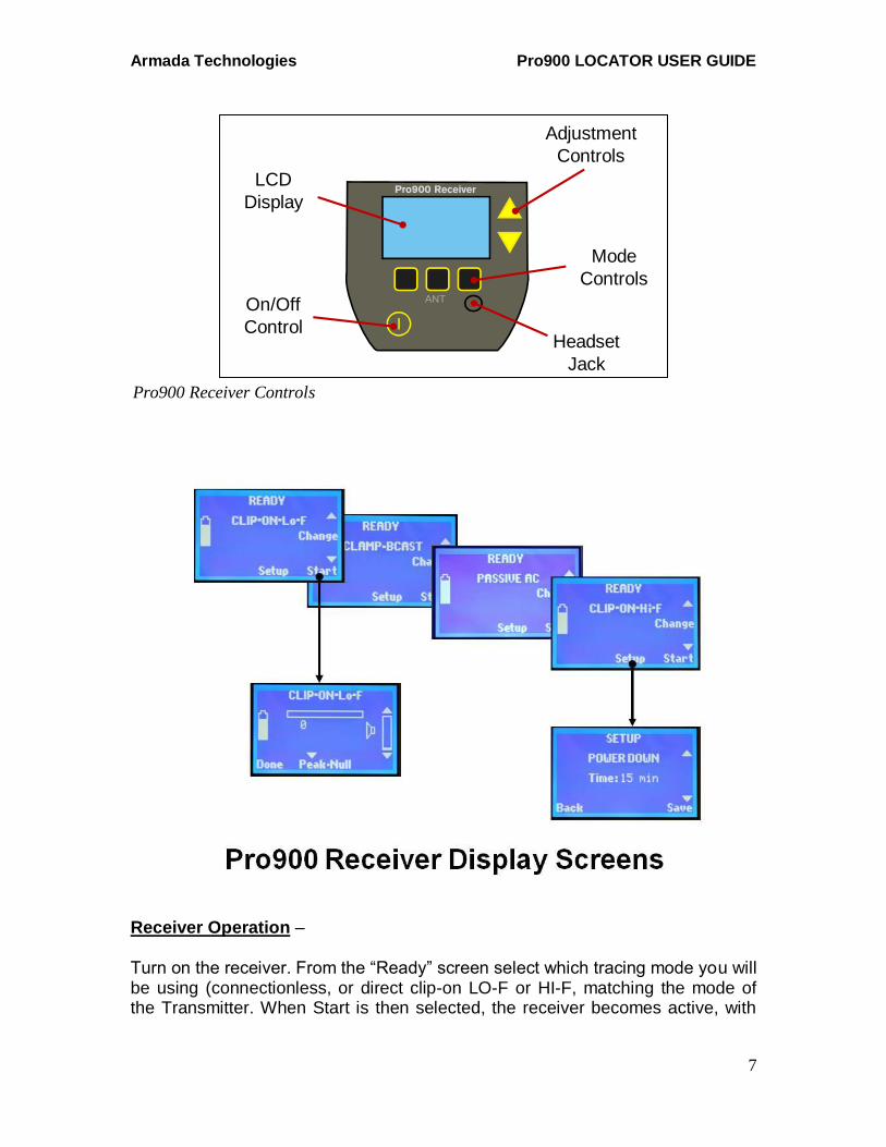
Receiver Operation –
Turn on the receiver. From the “Ready” screen select which tracing mode you will be using (connectionless, or direct clip-on LO-F or HI-F, matching the mode of the Transmitter. When Start is then selected, the receiver becomes active, with
Pro900 Receiver Controls
Pro900 Receiver
ANT
LCD
Display
On/Off
ControlHeadset
Jack
Adjustment
Controls
Mode
Controls
Armada Technologies Pro900 LOCATOR USER GUIDE
8
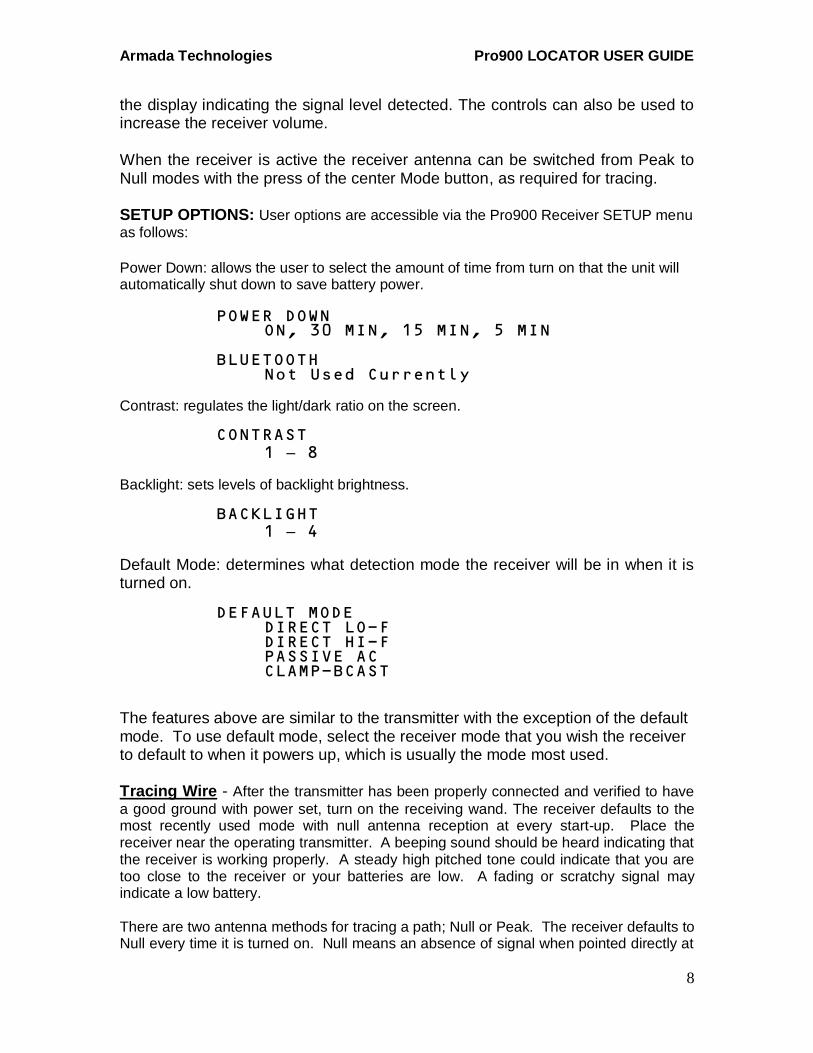
the display indicating the signal level detected. The controls can also be used to increase the receiver volume. When the receiver is active the receiver antenna can be switched from Peak to Null modes with the press of the center Mode button, as required for tracing. SETUP OPTIONS: User options are accessible via the Pro900 Receiver SETUP menu
as follows:
Power Down: allows the user to select the amount of time from turn on that the unit will automatically shut down to save battery power.
POWER DOWN ON, 30 MIN, 15 MIN, 5 MIN
BLUETOOTH Not Used Currently
Contrast: regulates the light/dark ratio on the screen. CONTRAST
1 – 8
Backlight: sets levels of backlight brightness.
BACKLIGHT 1 – 4
Default Mode: determines what detection mode the receiver will be in when it is turned on.
DEFAULT MODE
DIRECT LO-F DIRECT HI-F PASSIVE AC CLAMP-BCAST
The features above are similar to the transmitter with the exception of the default mode. To use default mode, select the receiver mode that you wish the receiver to default to when it powers up, which is usually the mode most used. Tracing Wire - After the transmitter has been properly connected and verified to have
a good ground with power set, turn on the receiving wand. The receiver defaults to the most recently used mode with null antenna reception at every start-up. Place the receiver near the operating transmitter. A beeping sound should be heard indicating that the receiver is working properly. A steady high pitched tone could indicate that you are too close to the receiver or your batteries are low. A fading or scratchy signal may indicate a low battery. There are two antenna methods for tracing a path; Null or Peak. The receiver defaults to Null every time it is turned on. Null means an absence of signal when pointed directly at
Armada Technologies Pro900 LOCATOR USER GUIDE
9
the cable in question and louder to the left and/or right of it a few inches. Peak means the opposite, that the signal is loudest over the cable. You may select which mode suits you best. In general, the closer you are to the cable, the louder the signal should be except for directly over the cable in the Null mode. The modes can also be flipped while tracing to give a better indication of path trace quality. In Direct Clip-on mode begin the wire trace by sweeping the area approximately 5-10 feet from the transmitter. Begin by searching for the null response. Until the null is acquired, you may receive audible responses of varying degrees. Follow the signal response until the signal is lost while marking the path as you trace. In the Broadcast mode the signal saturates a circle for at least 20 feet around the transmitter, so you must begin by walking out of that area, then circling to find the traced wire or pipe.
NOTE – The receiver and transmitter must always be in the same mode to operate correctly.
The selector arrows on the receiver control panel regulate the volume level of the receiver, both headphones and external speaker. Additionally, the signal bar on the receiver display will indicate the signal level visually. After connecting and turning on the transmitter and the receiver, point the receiver toward the ground in the direction of the cable and listen for the beeping signal.
Additionally, the feedback of your locate is given in 3 manners; audible external speaker, headset, or signal meter. Any of these three options indicate signal strength that is being received by the Pro900.
Finding Faults – Breaks or severe wire damage can be found with the Pro900. The
setup of the unit is the same as when tracing wire. The difference comes in the reception. Whereas the traced wire continues to emit a signal along the path of the cable, a break will cause the signal to stop at the point of the break. A nick or damage will cause the signal drop to a lower level but not necessarily end. Either the speaker or the analog meter on the receiver will indicate this drop. Be sure the cable or wire you are tracking is grounded – this completes a ‘loop’ for tracing current signal. To trace a cable, it must be grounded, either mechanically or capacitively. Mechanical means a direct physical ground at one end. Capacitive grounding generally applies to cable buried directly in the earth. The signal needs a path to return to the ground stake and without it, you will not get a good locate. A bad ground is indicated on the transmitter output signal meter when an OK or mid-range signal level doesn’t appear even at full power. In many cases, a direct buried cable fault will provide this grounding and allow for a cable to be located. A general rule is the greater the damage to a cable, the greater the drop off in signal at the point of damage. Conversely, minimal damage or weak grounding will show little change. This is an art and small faults are sometimes difficult to locate. Practice and experience will help immensely in this task.
Armada Technologies Pro900 LOCATOR USER GUIDE
10
If the damage is too small to locate and has a path to ground, consider using a ground fault locator like the GFL3000. Small damage to cables, like shovel nicks or gopher chews, are very difficult to locate with a locator. Ground fault locators are designed to find exactly that kind of fault. More information on ground fault locating and the GFL3000 can be found at our website www.armadatech.com.
Finding Irrigation Solenoids and Valves – There are generally two accepted
methods to find a lost solenoid/valve. The first method is to connect the red lead of the transmitter to the station wire leading to that valve and the black to ground as described above. We refer to this as the ‘unbalanced’ method. Operate the Pro900 as above and begin your locate. When you reach the point where a valve/solenoid is located, the signal will expand into a large (approx. 2-4ft) diameter area of signal. Many times this signal volume will get louder. This is your indication that you are over a valve or solenoid. The second method starts by tracing the wire path as previously described. Once the wire path has been traced you must power the transmitter off, remove the black lead from the earth ground and connect it to the common wire. We call this the ‘balanced’ method. In the case of multiple common wires it is suggested that you isolate and connect to the common wire that services the target valve. Connecting to multiple commons will work, however it weakens the signal response.
Power the transmitter on and adjust the output signal to suit your needs. High power output is not necessary and will limit battery life. It is advised that you once again point the receiver at the transmitter to assure that both units are on and functioning properly.
Slowly follow the pre-marked wire path. There will be an absence of signal response due to cancelling of the closely parallel wires until you near the valve. As you move closer to the valve the receiver will begin making a chattering sound which will intensify and distort, turn the volume down and take your time.
Even with the volume at its lowest setting the response of the valve solenoid will be very loud. Pinpointing the exact location of the solenoid is possible by decreasing the volume and taking your time. The lower the volume is, the more accurate you can be.
Slowly start moving the receiver in an X pattern above the high pitched area, continue reducing the volume while moving the tip of the receiver closer to the ground. Between the proximity of the receiver tip to the ground and the reduction in volume you can tell exactly where the valve solenoid is. Use a pointed probe to find the outline of the valve box before excavating. This will assure that unwanted damage isn't a result of your locate. Once the valve is located, verify that it is indeed your target either manually, with the Pro48, or from the controller. There may be more than one valve on the cable being traced. You may wish to continue past the first valve located to determine if other valves are also located on this wire.
Broadcast Mode – Broadcast mode is connectionless and different from using the
direct clip-on method of connection that has previously been discussed. It is not as
Armada Technologies Pro900 LOCATOR USER GUIDE
11
precise or strong as direct connecting, but when access to cables is limited or just a quick scan is required, Broadcast Mode can be very useful.
Broadcast mode is excellent for finding telephone or cable TV lines. It is less useful with wires attached to solenoids. The principle in use with Broadcast mode is AC induction. On ordinary wires, that works well. And it can work for sprinkler wire but the solenoid sometimes has to be eliminated from the circuit. This can be done by disconnecting the solenoid and grounding the wire manually. The problem is that the solenoid acts as a signal dampener with AC inductance. By removing the solenoid from the circuit, you can find sprinkler wires in broadcast mode. Deactivated 2-Wire systems do not have this issue and are traceable as they exist in the ground. Broadcast mode uses an inductive antenna located in the transmitter case to broadcast a signal around the case in an approximately 25 foot radius in all directions. It allows the user to transmit or induce signal from the transmitter directly into the ground. Any grounded metallic cable or pipe traveling through this electromagnetic field will pick up at least some of the tracing signal, making that conductor traceable with the wand.
Place the transmitter on the ground over the cable you wish to trace and select Broadcast to begin. A vertical position of the case increases the power induced into the ground. The transmitter is now inducing signal approximately 20 to 25 feet from it, and energizing any conductors in that field. You may now trace any conductor that has picked up that signal.
Also note, when the user is within 20 to 25 feet of the transmitter, you cannot trace a cable because the signal from the case itself will overpower the induced cable signal. The user will always hear the transmitter signal within 20 feet of the transmitter case. The Broadcast mode does not have a power output adjustment on the transmitter. In addition, remember that ALL conductors in the ground that can pick up the signal will. Therefore, tracking is better in non-congested areas. It is important to understand the uses and limitations of Broadcast Mode when compared to direct connection with the alligator clips.
Inductive Clamp Mode –To use the IC2 clamp, plug the clamp into the clamp
receptacle on the Pro900 transmitter and place the transmitter in the “Broadcast or Clamp” mode. Clamp the IC2 around the cable or pipe to be traced. Please note, the clamp must be placed between grounding points on each end of the cable and the cable must be grounded on both ends for the clamp to work. The clamp induces current onto the cable and the current will not flow if the cable isn’t grounded on both ends. You can increase the effectiveness of the clamp by wrapping the wire around the clamp as many times as possible. Like a transformer, the more wraps, the more power. Tracing Live Electrical Lines using Passive Mode - The Pro900 receiver has the
capability of detecting live electrical AC lines in the ground without connecting to them. This is known as Passive AC mode. In passive mode, no transmitter is used.
Armada Technologies Pro900 LOCATOR USER GUIDE
12
DO NOT ATTEMPT TO CONNECT THE ALLIGATOR LEADS OR ANY OTHER Pro900 COMPONENT TO LIVE ELECTRICAL LINES. DEATH OR INJURY COULD OCCUR.
To use the passive mode, turn on the Pro900 wand and select the Passive AC mode using the control panel. This switches the receiver into an unfiltered mode that detects the electrical field generated by 50Hz or 60Hz electrical current. Once the Pro900 wand is on, simply search an area until you hear a buzzing sound. There is no beeping signal as the transmitter is not used. Follow the buzzing sound in either null or peak mode, both will work, to track the cable. DO NOT RELY ON THE 50/60 Hz PASSIVE MODE AS THE SOLE METHOD OF LOCATING POWER LINES. Passive mode may not
detect power cabling if there is no live electrical current present in the cable at the time.
How to determine depth - Find the null over the wire path and mark it. Then place
the tip of the receiver on the ground at the mark. Without lifting the receiver tip from the ground, lower the top of the receiver to approximately a 45 degree angle and slowly walk the receiver away from the wire path until you re-acquire the null. The distance between the wire path and the newly established null is the approximate depth of the target. This is the Equilateral Triangle method.
Determining target accuracy - This is a very easy to perform method of determining
target accuracy. Place the tip of the receiver on the ground directly over your suspected target location, switch from null to peak by pressing the mode selection pad. The peak and null responses will agree if the locate is accurate. If the peak and null are off by more than a few inches the location is not accurate. Toggling between the null and peak modes often when locating the wire path will assure you of accuracy and help build your confidence.
Armada Technologies Pro900 LOCATOR USER GUIDE
13
Helpful Hints – Increases in signal strength and/or the size of the area it is occurring from usually indicates some type of anomaly in the cabling. Things that could cause this are valves (as described above), nicks, cuts, bad splices, or cut wires. Cable in good condition does not normally change the tone or strength, other than a very gradual loss of reception over distance, but it is possible. Slack loops of extra wire left in the ground at installation are an example of a condition that would cause an increase of signal and yet have no problem.
Also, soil condition makes a huge difference in the performance of cable locators. Basically a circuit is being created from the transmitter, through the cable, out through the ground and back to the ground stake. Any discontinuity in any of these links will cause the locator to not work. Be sure your ground stake is secure and in the dirt and that the transmitter is connected to the cable you want to track. The soil serves as the return path for the circuit. When using direct connection methods, you may have to condition dry or sandy soils to increase the conductivity of the soil by adding a little water at the ground stake. The best way to really learn the Pro900 is to use it. Set up a test site at your home or office and get used to how it works. There is no substitute for experience in the art of locating. In addition, our website has many training videos under the training tab which can be accessed 24/7. We also have available technical support with live human beings Monday through Friday from 8am to 4:30pm EST.

Armada Technologies Pro900 LOCATOR USER GUIDE
14
SPECIFICATIONS Tracking Range Depth: 8 feet (2.4 m)
(LO-F, 2kHz) Wire length: 5,000 feet (1.5 km) with direct connection Wire length: unlimited with broadcast mode and leapfrogging Tracking Signals Frequency One (LO-F): 2 kHz direct connect
Frequency Two (HI-F): 33 kHz direct connect Frequency Three (BCAST): 175 kHz via clamp or internal antenna Passive AC: 50/60 Hz
Antennas Receive Peak – 2/33 kHz Receive Null – 2/33 kHz Receive Peak – 175 kHz Transmit Internal – 175 kHz Clamp Interior Diameter 3.5 inches (85 mm)
Direct Connect Signal Output 900 V peak with no load
1 W maximum Audio Output Headset and Loudspeaker Power Source Transmitter: Eight (8) ‘D’ cells (LR20) alkaline or NiMH, or External 120 Vac Powering Receiver: One (1) 9 V (6LR61)
Warranty – Armada Technologies warranties all products for 12 months from manufacturing defects from the date of retail purchase. Armada Technologies will repair or replace any component that is returned to Armada Technologies within 12 months of purchase and does not exhibit signs of abuse or misuse. It is Armada Technologies sole discretion to determine this condition. Armada Technologies also reserves the right to require a proof of purchase in order to determine date and validity of purchase. Batteries are not covered by warranty.
Armada Technologies Equipment Inc. 3596 76
th St. SE
Caledonia, MI 49316 USA 616-803-1080
www.armadatech.com
REV 07/20 E