ARM Compiler toolchain Developing Software for ARM Processors
186
Copyright © 2010-2012 ARM. All rights reserved. ARM DUI 0471G (ID021412) ARM ® Compiler toolchain Version 5.01 Developing Software for ARM Processors
Transcript of ARM Compiler toolchain Developing Software for ARM Processors

ARM® Compiler toolchainVersion 5.01
Developing Software for ARM Processors
Copyright © 2010-2012 ARM. All rights reserved.ARM DUI 0471G (ID021412)

ARM Compiler toolchainDeveloping Software for ARM Processors
Copyright © 2010-2012 ARM. All rights reserved.
Release Information
The following changes have been made to this book.
Proprietary Notice
Words and logos marked with ® or ™ are registered trademarks or trademarks of ARM® in the EU and other countries, except as otherwise stated below in this proprietary notice. Other brands and names mentioned herein may be the trademarks of their respective owners.
Neither the whole nor any part of the information contained in, or the product described in, this collection may be adapted or reproduced in any material form except with the prior written permission of the copyright holder.
The product described in this collection is subject to continuous developments and improvements. All particulars of the product and its use contained in this collection are given by ARM in good faith. However, all warranties implied or expressed, including but not limited to implied warranties of merchantability, or fitness for purpose, are excluded.
This collection is intended only to assist the reader in the use of the product. ARM shall not be liable for any loss or damage arising from the use of any information in this collection, or any error or omission in such information, or any incorrect use of the product.
Where the term ARM is used it means “ARM or any of its subsidiaries as appropriate”.
Confidentiality Status
This document is Non-Confidential. The right to use, copy and disclose this document may be subject to license restrictions in accordance with the terms of the agreement entered into by ARM and the party that ARM delivered this document to.
Product Status
The information in this document is final, that is for a developed product.
Web Address
http://www.arm.com
Change History
Date Issue Confidentiality Change
May 2010 A Non-Confidential ARM Compiler toolchain v4.1 Release
07 October 2010 B Non-Confidential Update 1 for ARM Compiler toolchain v4.1
28 January 2011 C Non-Confidential Update 2 for ARM Compiler toolchain v4.1 Patch 3
30 April 2011 D Non-Confidential ARM Compiler toolchain v5.0 Release
29 July 2011 E Non-Confidential Update 1 for ARM Compiler toolchain v5.0
30 September 2011 F Non-Confidential ARM Compiler toolchain v5.01 Release
29 February 2012 G Non-Confidential Document update 1 for ARM Compiler toolchain v5.01 Release
ARM DUI 0471G Copyright © 2010-2012 ARM. All rights reserved. iiID021412 Non-Confidential
ContentsARM Compiler toolchain Developing Software for ARM Processors
Chapter 1 Conventions and feedback
Chapter 2 Key Features of ARM Architecture Versions2.1 About the ARM architectures ................................................................................... 2-22.2 Multiprocessing systems .......................................................................................... 2-42.3 Considerations when designing software for a multiprocessing system .................. 2-52.4 Tightly coupled memory ........................................................................................... 2-62.5 Memory management .............................................................................................. 2-72.6 Thumb-2 technology ................................................................................................ 2-82.7 ARM and Thumb floating-point build options (ARMv6 and earlier) .......................... 2-92.8 ARM and Thumb floating-point build options (ARMv7 and later) ........................... 2-102.9 ARM architecture v4T ............................................................................................ 2-112.10 ARM architecture v5TE .......................................................................................... 2-132.11 ARM architecture v6 .............................................................................................. 2-152.12 ARM architecture v6-M .......................................................................................... 2-182.13 ARM architecture v7-A ........................................................................................... 2-202.14 ARM architecture v7-R .......................................................................................... 2-222.15 ARM architecture v7-M .......................................................................................... 2-24
Chapter 3 Embedded Software Development3.1 About embedded software development ................................................................. 3-23.2 Default compilation tool behavior ............................................................................. 3-33.3 C library structure .................................................................................................... 3-43.4 Default memory map ............................................................................................... 3-53.5 Application startup ................................................................................................... 3-73.6 Tailoring the C library to your target hardware ........................................................ 3-83.7 Tailoring the image memory map to your target hardware .................................... 3-10
ARM DUI 0471G Copyright © 2010-2012 ARM. All rights reserved. iiiID021412 Non-Confidential
Contents
3.8 Scatter-loading description file ............................................................................... 3-113.9 Root regions .......................................................................................................... 3-123.10 Placing the stack and heap .................................................................................... 3-133.11 Run-time memory models ...................................................................................... 3-143.12 Scatter-loading file with link to bit-band objects ..................................................... 3-163.13 Reset and initialization ........................................................................................... 3-173.14 The vector table ..................................................................................................... 3-193.15 ROM and RAM remapping .................................................................................... 3-203.16 Local memory setup considerations ...................................................................... 3-213.17 Stack pointer initialization ...................................................................................... 3-223.18 Hardware initialization ............................................................................................ 3-233.19 Execution mode considerations ............................................................................. 3-243.20 Target hardware and the memory map ................................................................. 3-25
Chapter 4 Mixing C, C++, and Assembly Language4.1 Instruction intrinsics, inline and embedded assembler ............................................ 4-24.2 Access to C global variables from assembly code .................................................. 4-44.3 Including system C header files from C++ ............................................................... 4-54.4 Including your own C header files from C++ ............................................................ 4-64.5 Mixed-language programming ................................................................................. 4-74.6 Rules for calling between C, C++, and assembly language .................................... 4-84.7 Rules for calling C++ functions from C and assembly language ............................. 4-94.8 Information specific to C++ .................................................................................... 4-104.9 Examples of calling between languages ................................................................ 4-114.10 Calls to assembly language from C ....................................................................... 4-124.11 Calls to C from assembly language ....................................................................... 4-134.12 Calls to C from C++ ............................................................................................... 4-144.13 Calls to assembly language from C++ ................................................................... 4-154.14 Calls to C++ from C ............................................................................................... 4-164.15 Calls to C++ from assembly language ................................................................... 4-174.16 Calls to C++ from C or assembly language ........................................................... 4-184.17 Passing a reference between C and C++ .............................................................. 4-20
Chapter 5 Interworking ARM and Thumb5.1 About interworking ................................................................................................... 5-25.2 When to use interworking ........................................................................................ 5-35.3 Assembly language interworking ............................................................................. 5-45.4 C and C++ interworking ........................................................................................... 5-55.5 Pointers to functions in Thumb state ....................................................................... 5-65.6 Using two versions of the same function ................................................................. 5-75.7 Assembly language interworking example .............................................................. 5-85.8 Interworking using veneers ................................................................................... 5-105.9 C and C++ language interworking ........................................................................ 5-125.10 C, C++, and assembly language interworking using veneers ................................ 5-14
Chapter 6 Handling Processor Exceptions6.1 About processor exceptions .................................................................................... 6-36.2 Exception handling process ..................................................................................... 6-46.3 Types of exception in ARMv6 and earlier, ARMv7-A and ARMv7-R profiles .......... 6-56.4 Vector table for ARMv6 and earlier, ARMv7-A and ARMv7-R profiles .................... 6-66.5 Processor modes and registers in ARMv6 and earlier, ARMv7-A and ARMv7-R profiles
6-76.6 Use of System mode for exception handling ........................................................... 6-86.7 The processor response to an exception ................................................................. 6-96.8 Return from an exception handler ......................................................................... 6-106.9 Reset handlers ....................................................................................................... 6-116.10 Data Abort handler ................................................................................................. 6-126.11 Interrupt handlers and levels of external interrupt ................................................. 6-136.12 Reentrant interrupt handlers .................................................................................. 6-146.13 Example interrupt handlers in assembly language ................................................ 6-17
ARM DUI 0471G Copyright © 2010-2012 ARM. All rights reserved. ivID021412 Non-Confidential

Contents
6.14 Single-channel DMA transfer ................................................................................. 6-186.15 Dual-channel DMA transfer ................................................................................... 6-196.16 Interrupt prioritization ............................................................................................. 6-206.17 Context switch ....................................................................................................... 6-226.18 SVC handlers ......................................................................................................... 6-236.19 Determining the SVC to be called .......................................................................... 6-256.20 SVC handlers in assembly language ..................................................................... 6-266.21 SVC handlers in C and assembly language .......................................................... 6-276.22 Using SVCs in Supervisor mode ........................................................................... 6-296.23 Calling SVCs from an application .......................................................................... 6-306.24 Calling SVCs dynamically from an application ...................................................... 6-326.25 Prefetch Abort handler ........................................................................................... 6-346.26 Undefined instruction handlers .............................................................................. 6-356.27 ARMv6-M and ARMv7-M profiles .......................................................................... 6-366.28 Main and Process Stacks ...................................................................................... 6-376.29 Types of exceptions in the microcontroller profiles ................................................ 6-386.30 Vector table for ARMv6-M and ARMv7-M profiles ................................................. 6-396.31 Vector Table Offset Register (ARMv7-M only) ...................................................... 6-406.32 Writing the exception table for ARMv6-M and ARMv7-M profiles .......................... 6-416.33 The Nested Vectored Interrupt Controller .............................................................. 6-426.34 Handling an exception ........................................................................................... 6-436.35 Configuring the System Control Space registers ................................................... 6-456.36 Configuring individual IRQs ................................................................................... 6-476.37 Supervisor calls ..................................................................................................... 6-486.38 System timer .......................................................................................................... 6-506.39 Configuring SysTick ............................................................................................... 6-51
Chapter 7 Debug Communications Channel7.1 About the Debug Communications Channel ............................................................ 7-27.2 DCC communication between target and host debug tools ..................................... 7-37.3 Interrupt-driven debug communications .................................................................. 7-47.4 Access from Thumb state ........................................................................................ 7-6
Chapter 8 Semihosting8.1 What is semihosting? ............................................................................................... 8-38.2 The semihosting interface ........................................................................................ 8-58.3 Can I change the semihosting operation numbers? ................................................ 8-78.4 Semihosting operations ........................................................................................... 8-88.5 Debug agent interaction SVCs ................................................................................ 8-98.6 angel_SWIreason_EnterSVC (0x17) ..................................................................... 8-108.7 angel_SWIreason_ReportException (0x18) .......................................................... 8-118.8 SYS_CLOSE (0x02) .............................................................................................. 8-138.9 SYS_CLOCK (0x10) .............................................................................................. 8-148.10 SYS_ELAPSED (0x30) .......................................................................................... 8-158.11 SYS_ERRNO (0x13) ............................................................................................. 8-168.12 SYS_FLEN (0x0C) ................................................................................................. 8-178.13 SYS_GET_CMDLINE (0x15) ................................................................................. 8-188.14 SYS_HEAPINFO (0x16) ........................................................................................ 8-198.15 SYS_ISERROR (0x08) .......................................................................................... 8-208.16 SYS_ISTTY (0x09) ................................................................................................ 8-218.17 SYS_OPEN (0x01) ................................................................................................ 8-228.18 SYS_READ (0x06) ................................................................................................ 8-238.19 SYS_READC (0x07) .............................................................................................. 8-248.20 SYS_REMOVE (0x0E) .......................................................................................... 8-258.21 SYS_RENAME (0x0F) ........................................................................................... 8-268.22 SYS_SEEK (0x0A) ................................................................................................ 8-278.23 SYS_SYSTEM (0x12) ............................................................................................ 8-288.24 SYS_TICKFREQ (0x31) ........................................................................................ 8-298.25 SYS_TIME (0x11) .................................................................................................. 8-308.26 SYS_TMPNAM (0x0D) .......................................................................................... 8-31
ARM DUI 0471G Copyright © 2010-2012 ARM. All rights reserved. vID021412 Non-Confidential

Contents
8.27 SYS_WRITE (0x05) ............................................................................................... 8-328.28 SYS_WRITEC (0x03) ............................................................................................ 8-338.29 SYS_WRITE0 (0x04) ............................................................................................. 8-34
Appendix A Revisions for Developing Software for ARM Processors
ARM DUI 0471G Copyright © 2010-2012 ARM. All rights reserved. viID021412 Non-Confidential

Chapter 1 Conventions and feedback
The following describes the typographical conventions and how to give feedback:
Typographical conventions The following typographical conventions are used:monospace Denotes text that can be entered at the keyboard, such as commands,
file and program names, and source code.monospace Denotes a permitted abbreviation for a command or option. The
underlined text can be entered instead of the full command or option name.
monospace italic Denotes arguments to commands and functions where the argument is to be replaced by a specific value.
monospace bold Denotes language keywords when used outside example code.
italic Highlights important notes, introduces special terminology, denotes internal cross-references, and citations.
bold Highlights interface elements, such as menu names. Also used for emphasis in descriptive lists, where appropriate, and for ARM® processor signal names.
Feedback on this product If you have any comments and suggestions about this product, contact your supplier and give:• your name and company
ARM DUI 0471G Copyright © 2010-2012 ARM. All rights reserved. 1-1ID021412 Non-Confidential

Conventions and feedback
• the serial number of the product• details of the release you are using• details of the platform you are using, such as the hardware platform,
operating system type and version• a small standalone sample of code that reproduces the problem• a clear explanation of what you expected to happen, and what actually
happened• the commands you used, including any command-line options• sample output illustrating the problem• the version string of the tools, including the version number and build
numbers.
Feedback on content If you have comments on content then send an e-mail to [email protected]. Give:• the title• the number, ARM DUI 0471G• if viewing online, the topic names to which your comments apply• if viewing a PDF version of a document, the page numbers to which your
comments apply• a concise explanation of your comments.ARM also welcomes general suggestions for additions and improvements.
ARM periodically provides updates and corrections to its documentation on the ARM Information Center, together with knowledge articles and Frequently Asked Questions (FAQs).
Other information • ARM Information Center, http://infocenter.arm.com/help/index.jsp• ARM Technical Support Knowledge Articles,
http://infocenter.arm.com/help/topic/com.arm.doc.faqs/index.html
• ARM Support and Maintenance, http://www.arm.com/support/services/support-maintenance.php
• ARM Glossary, http://infocenter.arm.com/help/topic/com.arm.doc.aeg0014-/index.html.
ARM DUI 0471G Copyright © 2010-2012 ARM. All rights reserved. 1-2ID021412 Non-Confidential

Chapter 2 Key Features of ARM Architecture Versions
The following topics describe the key features for each version of the ARM® architecture and identify some of the main points to be aware of when using ARM Compiler toolchain:• About the ARM architectures on page 2-2• Multiprocessing systems on page 2-4• Considerations when designing software for a multiprocessing system on page 2-5• Tightly coupled memory on page 2-6• Memory management on page 2-7• Thumb-2 technology on page 2-8• ARM and Thumb floating-point build options (ARMv6 and earlier) on page 2-9• ARM and Thumb floating-point build options (ARMv7 and later) on page 2-10• ARM architecture v4T on page 2-11• ARM architecture v5TE on page 2-13• ARM architecture v6 on page 2-15• ARM architecture v6-M on page 2-18• ARM architecture v7-A on page 2-20• ARM architecture v7-R on page 2-22• ARM architecture v7-M on page 2-24.
ARM DUI 0471G Copyright © 2010-2012 ARM. All rights reserved. 2-1ID021412 Non-Confidential

Key Features of ARM Architecture Versions
2.1 About the ARM architectures
The ARM architecture defines the ARM and Thumb® instruction sets, execution models, memory models and debug models used by ARM processors. Variants of the memory models might include virtual memory, caches, Tightly Coupled Memory (TCM), and memory protection. ARM architecture extensions define additional features such as floating-point support, Single Instruction Multiple Data (SIMD) instructions, Security extensions, Java bytecode acceleration, and Multiprocessing support.
The ARM architecture is constantly evolving to meet the increasing demands of leading edge applications developers, while retaining the backwards compatibility necessary to protect investment in software development.
The following table shows some key features for the current ARM processors.
Table 2-1 Key features
Processor ArchitectureTightly Coupled Memory
Memory Management
Thumb®-2 technology
ARM7TDMI® ARMv4T - - -
ARM920T™ ARMv4T - MMU -
ARM922T™ ARMv4T - MMU -
ARM926EJ-S™ ARMv5TEJ Yes MMU -
ARM946E-S™ ARMv5TE Yes MPU -
ARM966E-S™ ARMv5TE Yes - -
ARM1136J-S™/ARM1136JF-S™ ARMv6K Yes MMU -
ARM1156T2-S™/ARM1156T2F-S™ ARMv6T2 Yes MPU Yes
ARM1176JZ-S™/ARM1176JZF-S™ ARMv6Z Yes MMU -
ARM11™ MPCore™ ARMv6K - MMU -
Cortex™-M0 ARMv6-M - - -
Cortex-M1 ARMv6-M Yes - -
Cortex-M3 ARMv7-M - MPU (optional) Yes, but without ARM instruction set
Cortex-M4 ARMv7E-M - MPU (optional) Yes, but without ARM instruction set
Cortex-A5 ARMv7-A - MMU Yes
Cortex-A7 ARMv7-A - MMU Yes
Cortex-A8 ARMv7-A - MMU Yes
Cortex-A9 ARMv7-A - MMU Yes
Cortex-A15 ARMv7-A - MMU Yes
Cortex-R4, Cortex-R4F, and Cortex-R7
ARMv7-R Yes MPU Yes
ARM DUI 0471G Copyright © 2010-2012 ARM. All rights reserved. 2-2ID021412 Non-Confidential

Key Features of ARM Architecture Versions
2.1.1 See also
Concepts: • Tightly coupled memory on page 2-6• Memory management on page 2-7• Thumb-2 technology on page 2-8.
Other information: • ARM Architecture Reference Manual,
http://infocenter/help/topic/com.arm.doc.subset.architecture.reference/index.html
• Technical Reference Manual for your processor.
ARM DUI 0471G Copyright © 2010-2012 ARM. All rights reserved. 2-3ID021412 Non-Confidential

Key Features of ARM Architecture Versions
2.2 Multiprocessing systemsThe ARM architecture v6K introduces the first MPCore processor supporting up to four CPUs and associated hardware. Applications have to be specifically designed to run on multiprocessing systems to optimize performance. For example, a single threaded application can only be executed by a single CPU at a time, whereas a multithreaded application can be executed by multiple processors in parallel. An efficient multiprocessing system consumes less power, produces less heat and is more responsive than a system with one CPU but is more complex and therefore more difficult to debug.
2.2.1 See also
Concepts • Considerations when designing software for a multiprocessing system on page 2-5.
ARM DUI 0471G Copyright © 2010-2012 ARM. All rights reserved. 2-4ID021412 Non-Confidential

Key Features of ARM Architecture Versions
2.3 Considerations when designing software for a multiprocessing systemConsider the following recommended guidelines when designing a multiprocessing system:
• synchronize software execution on processors using LDREX and STREX to create a mutex or semaphore to protect critical sections and non-shareable resources
• manage cache coherency for symmetrical and asymmetrical multiprocessing
• execute repetitive tasks in separate threads
• split a large task into several threads executing in parallel
• set up a primary CPU using the CP15 CPU ID register for initialization tasks
• prioritize interrupts
• use bit masking for interrupt pre-emption
• configure the cycle counts that trigger a timer or watchdog.
Note These tasks are generally handled by an OS.
2.3.1 See also
Concepts • Multiprocessing systems on page 2-4.
Reference: • LDREX and STREX on page 3-40.
ARM DUI 0471G Copyright © 2010-2012 ARM. All rights reserved. 2-5ID021412 Non-Confidential

Key Features of ARM Architecture Versions
2.4 Tightly coupled memoryThe purpose of Tightly Coupled Memory (TCM) is to provide low-latency memory that the processor can use without the unpredictability that is a feature of caches. You can use TCM to hold time-critical routines, such as interrupt handling routines or real-time tasks where the indeterminacy of a cache is highly undesirable. In addition, you can use it to hold ordinary variables, data types whose locality properties are not well suited to caching, and critical data structures such as interrupt stacks.
TCM is used as part of the physical memory map of the system, and does not have to be backed by a level of external memory with the same physical addresses. In such regions, no external writes occur in the event of a write to memory locations contained in the TCM.
2.4.1 See also
Other information • ARM Architecture Reference Manual,
http://infocenter/help/topic/com.arm.doc.subset.architecture.reference/index.html
• Technical Reference Manual for your processor.
ARM DUI 0471G Copyright © 2010-2012 ARM. All rights reserved. 2-6ID021412 Non-Confidential

Key Features of ARM Architecture Versions
2.5 Memory managementThe ARM memory management options are:
MMU The Memory Management Unit (MMU) allows fine-grained control of a memory system, which allows an operating system to provide features such as demand memory paging. Most of the detailed control is provided through translation tables held in memory. Entries in these tables define the properties for different regions of memory. These include:• virtual-to-physical address mapping• memory access permissions• memory types.
MPU The Memory Protection Unit (MPU) provides a considerably simpler alternative to the MMU. This allows both hardware and software to be simplified in systems that do not require all facilities of the MMU. You can use the MPU to partition external memory into separate contiguous regions with different sizes and attributes. You can also control access permissions and memory characteristics for different regions of memory.An MPU does not require external memory for translation tables and helps to provide more predictable performance than an MMU.
2.5.1 See also
Other information • ARM Architecture Reference Manual,
http://infocenter/help/topic/com.arm.doc.subset.architecture.reference/index.html
• Technical Reference Manual for your processor.
ARM DUI 0471G Copyright © 2010-2012 ARM. All rights reserved. 2-7ID021412 Non-Confidential
Key Features of ARM Architecture Versions
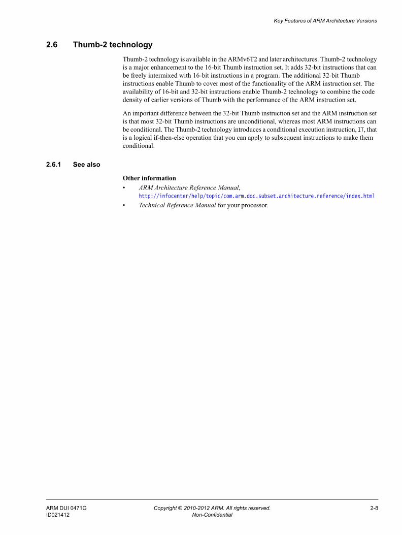
2.6 Thumb-2 technologyThumb-2 technology is available in the ARMv6T2 and later architectures. Thumb-2 technology is a major enhancement to the 16-bit Thumb instruction set. It adds 32-bit instructions that can be freely intermixed with 16-bit instructions in a program. The additional 32-bit Thumb instructions enable Thumb to cover most of the functionality of the ARM instruction set. The availability of 16-bit and 32-bit instructions enable Thumb-2 technology to combine the code density of earlier versions of Thumb with the performance of the ARM instruction set.
An important difference between the 32-bit Thumb instruction set and the ARM instruction set is that most 32-bit Thumb instructions are unconditional, whereas most ARM instructions can be conditional. The Thumb-2 technology introduces a conditional execution instruction, IT, that is a logical if-then-else operation that you can apply to subsequent instructions to make them conditional.
2.6.1 See also
Other information • ARM Architecture Reference Manual,
http://infocenter/help/topic/com.arm.doc.subset.architecture.reference/index.html
• Technical Reference Manual for your processor.
ARM DUI 0471G Copyright © 2010-2012 ARM. All rights reserved. 2-8ID021412 Non-Confidential

Key Features of ARM Architecture Versions
2.7 ARM and Thumb floating-point build options (ARMv6 and earlier)There are several options for compiling code that carries out floating-point operations in ARM code and Thumb code:
ARM only Choose the option --fpu vfpv2 to have the compiler generate ARM code only for functions containing floating-point operations.When the option --fpu vfpv2 is selected, the compiler generates ARM code for any function containing floating-point operations, regardless of whether the compiler is compiling for ARM or compiling for Thumb. This is because the Thumb instruction set, in ARMv6 and earlier, does not contain VFP instructions and therefore cannot access VFP registers. This uses hardware VFP linkage, which means floating-point arguments are passed in floating-point registers.When compiling for ARM only, use --fpu=vfpv2 and not --fpu=softvfp+vfpv2. Software linkage adds an overhead in transfer values between VFP and ARM that slows down the transfers and requires additional instructions.
Mixed ARM/Thumb Choose the option --fpu softvfp+vfpv2 to have the compiler generate mixed ARM/Thumb code.When the option --fpu softvfp+vfpv2 is selected, all functions are compiled using software floating-point linkage. This means that floating-point arguments are passed to and returned from functions in integer registers.The Thumb instruction set, in ARMv6 and earlier, does not contain VFP instructions and therefore cannot access VFP registers. When you compile for Thumb, setting --fpu=softvfp+vfpv2 enables the use of ARM Compiler libraries that enable access to the VFP registers using software linkage.The libraries include software floating point functions that are compiled for ARM and use VFP instructions. These library functions give improved performance and reduced code size compared to the full software floating point functions.
The option that provides the best code size or performance depends on the code being compiled. When compiling for ARM, experiment with the options --fpu softvfp+vfpv2 and --fpu vfpv2 to determine which provides the required code size and performance attributes.
If you have a mix of ARM and Thumb then you might want to experiment with the --fpu option to get the best results.
2.7.1 See also
Reference Assembler Reference:• --fpu=name on page 2-14.
Other information • ARM Architecture Reference Manual,
http://infocenter/help/topic/com.arm.doc.subset.architecture.reference/index.html
• Technical Reference Manual for your processor.
ARM DUI 0471G Copyright © 2010-2012 ARM. All rights reserved. 2-9ID021412 Non-Confidential

Key Features of ARM Architecture Versions
2.8 ARM and Thumb floating-point build options (ARMv7 and later)Mixed ARM/Thumb
Choose the option --fpu softvfp+vfpv3 to have the compiler generate mixed ARM/Thumb code.When the option --fpu softvfp+vfpv3 is selected, all functions are compiled using software floating-point linkage. This means that floating-point arguments are passed to and returned from functions in ARM integer registers.Software floating-point linkage enables you to link with generic libraries and legacy code that are themselves built with software floating-point linkage.
ARM only Choose the options --arm --fpu vfpv3 to have the compiler generate ARM code only. This uses hardware VFP linkage.
Thumb only Choose the options --thumb --fpu vfpv3 to have the compiler generate Thumb code for your entire program. The 32-bit Thumb instruction set supports VFP instructions. Therefore, there is no need to switch to ARM state to perform VFP operations. This uses hardware VFP linkage.
Note This option is available only for ARMv7 processors with VFPv3, for example the
Cortex-A8, where VFP is directly accessible from both the ARM and the 32-bit Thumb instruction set.
2.8.1 See also
Reference Assembler Reference:• --fpu=name on page 2-14.
Other information • ARM Architecture Reference Manual,
http://infocenter/help/topic/com.arm.doc.subset.architecture.reference/index.html
• Technical Reference Manual for your processor.
ARM DUI 0471G Copyright © 2010-2012 ARM. All rights reserved. 2-10ID021412 Non-Confidential

Key Features of ARM Architecture Versions
2.9 ARM architecture v4TThis is an overview of the compilation tools support for ARMv4T. This variant of the ARM architecture supports 16-bit Thumb instructions and the ARM instruction set. The following table shows useful command-line options.
2.9.1 Key features
When compiling code for ARMv4T, the compiler supports the 16-bit Thumb instruction set. This provides greater code density, however:
• Thumb code usually uses more instructions for a given task, making ARM code best for maximizing performance of time-critical code.
• ARM state and associated ARM instructions are required for exception handling
• ARM instructions are required for coprocessor accesses including cache configuration (on cached processors) and VFP.
2.9.2 Alignment support
All load and store instructions must specify addresses that are aligned on a natural alignment boundary. For example:• LDR and STR addresses must be aligned on a word boundary• LDRH and STRH addresses must be aligned on a halfword boundary• LDRB and STRB addresses can be aligned to any boundary.
Accesses to addresses that are not on a natural alignment boundary result in UNPREDICTABLE behavior. To control this you must inform the compiler, using __packed, when you want to access an unaligned address so that it can generate safe code.
Note Unaligned accesses, where permitted, are treated as rotated aligned accesses.
2.9.3 Endian support
You can produce either little-endian or big-endian code using the compiler command-line options --littleend and --bigend respectively.
ARMv4T supports the following endian modes:LE little-endian formatBE-32 legacy big-endian format.
Table 2-2 Useful command-line options
Command-line option Description
--cpu=4T ARMv4 with 16-bit Thumb.
--cpu=name Where name is a specific ARM processor. For example ARM7TDMI.
--apcs=qualifier Where qualifier denotes one or more qualifiers for interworking and position independence. For example --apcs=/interwork.
ARM DUI 0471G Copyright © 2010-2012 ARM. All rights reserved. 2-11ID021412 Non-Confidential

Key Features of ARM Architecture Versions
2.9.4 See also
Reference Using the Compiler:• Chapter 2 Overview of the Compiler. Compiler Reference:• __packed on page 5-17.Assembler Reference:• --apcs=qualifier…qualifier on page 2-5• --cpu=name on page 2-8• --bigend on page 2-6• --littleend on page 2-18.
ARM DUI 0471G Copyright © 2010-2012 ARM. All rights reserved. 2-12ID021412 Non-Confidential
Key Features of ARM Architecture Versions
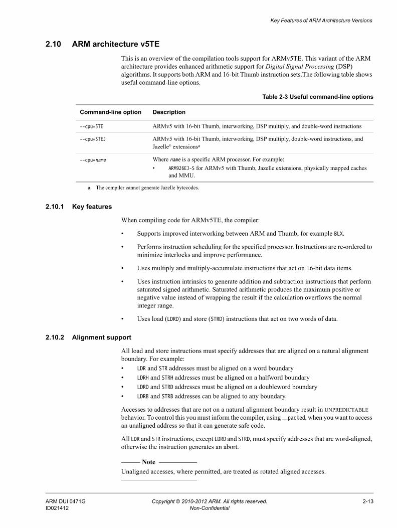
2.10 ARM architecture v5TEThis is an overview of the compilation tools support for ARMv5TE. This variant of the ARM architecture provides enhanced arithmetic support for Digital Signal Processing (DSP) algorithms. It supports both ARM and 16-bit Thumb instruction sets.The following table shows useful command-line options.
2.10.1 Key features
When compiling code for ARMv5TE, the compiler:
• Supports improved interworking between ARM and Thumb, for example BLX.
• Performs instruction scheduling for the specified processor. Instructions are re-ordered to minimize interlocks and improve performance.
• Uses multiply and multiply-accumulate instructions that act on 16-bit data items.
• Uses instruction intrinsics to generate addition and subtraction instructions that perform saturated signed arithmetic. Saturated arithmetic produces the maximum positive or negative value instead of wrapping the result if the calculation overflows the normal integer range.
• Uses load (LDRD) and store (STRD) instructions that act on two words of data.
2.10.2 Alignment support
All load and store instructions must specify addresses that are aligned on a natural alignment boundary. For example:• LDR and STR addresses must be aligned on a word boundary• LDRH and STRH addresses must be aligned on a halfword boundary• LDRD and STRD addresses must be aligned on a doubleword boundary• LDRB and STRB addresses can be aligned to any boundary.
Accesses to addresses that are not on a natural alignment boundary result in UNPREDICTABLE behavior. To control this you must inform the compiler, using __packed, when you want to access an unaligned address so that it can generate safe code.
All LDR and STR instructions, except LDRD and STRD, must specify addresses that are word-aligned, otherwise the instruction generates an abort.
Note Unaligned accesses, where permitted, are treated as rotated aligned accesses.
Table 2-3 Useful command-line options
Command-line option Description
--cpu=5TE ARMv5 with 16-bit Thumb, interworking, DSP multiply, and double-word instructions
--cpu=5TEJ ARMv5 with 16-bit Thumb, interworking, DSP multiply, double-word instructions, and Jazelle® extensionsa
--cpu=name Where name is a specific ARM processor. For example:• ARM926EJ-S for ARMv5 with Thumb, Jazelle extensions, physically mapped caches
and MMU.
a. The compiler cannot generate Jazelle bytecodes.
ARM DUI 0471G Copyright © 2010-2012 ARM. All rights reserved. 2-13ID021412 Non-Confidential

Key Features of ARM Architecture Versions
2.10.3 Endian support
You can produce either little-endian or big-endian code using the compiler command-line options --littleend and --bigend respectively.
ARMv5TE supports the following endian modes:LE little-endian formatBE-32 legacy big-endian format.
2.10.4 See also
Tasks Using the Compiler:• Compiler storage of data objects by natural byte alignment on page 6-43.
Concepts Using the Compiler:• __packed on page 5-17.
Reference Compiler Reference:• --unaligned_access, --no_unaligned_access on page 3-206.Assembler Reference:• --cpu=name on page 2-8• --bigend on page 2-6• --littleend on page 2-18.
Other information • Technical Reference Manual for your processor.
ARM DUI 0471G Copyright © 2010-2012 ARM. All rights reserved. 2-14ID021412 Non-Confidential

Key Features of ARM Architecture Versions
2.11 ARM architecture v6This is an overview of the compilation tools support for ARMv6. This variant of the ARM architecture extends the original ARM instruction set to support multi-processing and adds some extra memory model features. It supports both ARM and Thumb instruction sets. The following table shows useful command-line options.
2.11.1 Key features
In addition to the features of ARMv5TE, when compiling code for ARMv6, the compiler:
• Performs instruction scheduling for the specified processor. Instructions are re-ordered to minimize interlocks and improve performance.
• Generates explicit SXTB, SXTH, UXTB, UXTH byte or halfword extend instructions where appropriate.
• Generates the endian reversal instructions REV, REV16 and REVSH if it can deduce that a C expression performs an endian reversal.
• Generates additional Thumb instructions available in ARMv6, for example CPS, CPY, REV, REV16, REVSH, SETEND, SXTB, SXTH, UXTB, UXTH.
• Uses some functions that are optimized specifically for ARMv6, for example, memcpy().
The compiler does not generate SIMD instructions automatically from ordinary C or C++ code because these do not map well onto C expressions. You must use assembly language or intrinsics for SIMD code generation.
Some enhanced instructions are available to improve exception handling:• SRS and RFE instructions to save and restore the Link Register (LR) and the Saved Program
Status Register (SPSR)• CPS simplifies changing state, and modifying the I and F bits in the Current Program
Status Register (CPSR)• architectural support for vectored interrupts with a vectored interrupt controller• low-latency interrupt mode• ARM1156T2-S can enter exceptions in Thumb state using 32-bit Thumb code.
Table 2-4 Useful command-line options
Option Description
--cpu=6 ARMv6 with 16-bit Thumb, interworking, DSP multiply, doubleword instructions, unaligned and mixed-endian support, Jazelle, and media extensions
--cpu=6Z ARMv6 with security extensions
--cpu=6T2 ARMv6 with 16-bit Thumb and 32-bit Thumb
--cpu=name Where name is a specific ARM processor. For example:• ARM1136J-S to generate code for the ARM1136J-S with software VFP support• ARM1136JF-S to generate code for the ARM1136J-S with hardware VFP
ARM DUI 0471G Copyright © 2010-2012 ARM. All rights reserved. 2-15ID021412 Non-Confidential
Key Features of ARM Architecture Versions
2.11.2 Alignment support
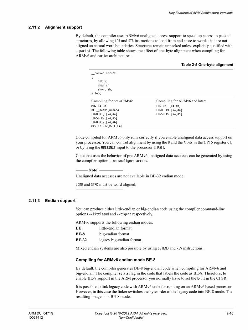
By default, the compiler uses ARMv6 unaligned access support to speed up access to packed structures, by allowing LDR and STR instructions to load from and store to words that are not aligned on natural word boundaries. Structures remain unpacked unless explicitly qualified with __packed. The following table shows the effect of one-byte alignment when compiling for ARMv6 and earlier architectures.
Code compiled for ARMv6 only runs correctly if you enable unaligned data access support on your processor. You can control alignment by using the U and the A bits in the CP15 register c1, or by tying the UBITINIT input to the processor HIGH.
Code that uses the behavior of pre-ARMv6 unaligned data accesses can be generated by using the compiler option --no_unaligned_access.
Note Unaligned data accesses are not available in BE-32 endian mode.
LDRD and STRD must be word aligned.
2.11.3 Endian support
You can produce either little-endian or big-endian code using the compiler command-line options --littleend and --bigend respectively.
ARMv6 supports the following endian modes:LE little-endian formatBE-8 big-endian formatBE-32 legacy big-endian format.
Mixed endian systems are also possible by using SETEND and REV instructions.
Compiling for ARMv6 endian mode BE-8
By default, the compiler generates BE-8 big-endian code when compiling for ARMv6 and big-endian. The compiler sets a flag in the code that labels the code as BE-8. Therefore, to enable BE-8 support in the ARM processor you normally have to set the E-bit in the CPSR.
It is possible to link legacy code with ARMv6 code for running on an ARMv6 based processor. However, in this case the linker switches the byte order of the legacy code into BE-8 mode. The resulting image is in BE-8 mode.
Table 2-5 One-byte alignment
__packed struct{
int i;char ch;short sh;
} foo;
Compiling for pre-ARMv6:MOV R4,R0BL __aeabi_uread4 LDRB R1, [R4,#4]LDRSB R2,[R4,#5]LDRB R12,[R4,#6]ORR R2,R12,R2 LSL#8
Compiling for ARMv6 and later:LDR R0, [R4,#0]LDRB R1,[R4,#4]LDRSH R2,[R4,#5]
ARM DUI 0471G Copyright © 2010-2012 ARM. All rights reserved. 2-16ID021412 Non-Confidential

Key Features of ARM Architecture Versions
Compiling for ARMv6 legacy endian mode BE-32
To use the pre-ARMv6 or legacy BE-32 mode you must tie the BIGENDINIT input into the processor HIGH, or set the B bit of CP15 register c1.
Note You must link BE-32 compatible code using the linker option --be32. Otherwise, the ARMv6 attributes causes a BE-8 image to be produced.
2.11.4 See also
Reference Using the Assembler:• Media processing instructions on page 3-24.Compiler Reference:• --littleend on page 3-136• --unaligned_access, --no_unaligned_access on page 3-206.Linker Reference:• --be8 on page 2-19• --be32 on page 2-20.Assembler Reference:• --cpu=name on page 2-8• --bigend on page 2-6• --littleend on page 2-18.
ARM DUI 0471G Copyright © 2010-2012 ARM. All rights reserved. 2-17ID021412 Non-Confidential

Key Features of ARM Architecture Versions
2.12 ARM architecture v6-MThis is an overview of the compilation tools support for ARMv6-M (ARMv6 architecture targeted at the microcontroller profile). Microcontroller profiles implement a programmers' model designed for fast interrupt processing, with hardware stacking of registers and support for writing interrupt handlers in high-level languages. The processor is designed for integration into an FPGA and is ideal for use in very low power applications. It supports the 16-bit Thumb instruction set and a small number of 32-bit Thumb instructions. The following table shows useful command-line options.
2.12.1 Key features
Key features for ARMv6-M:
• The compiler supports the 16-bit Thumb instruction set and a small number of 32-bit Thumb instructions. The 32-bit instructions are BL, DMB, DSB, ISB, MRS, and MSR.
2.12.2 Alignment support
By default, the compiler uses ARMv6 unaligned access support to speed up access to packed structures, by allowing LDR and STR instructions to load from and store to words that are not aligned on natural word boundaries.
Unaligned data accesses are converted into two or three aligned accesses, depending on the size and alignment of the unaligned access. This stalls any subsequent accesses until the unaligned access has completed. You can control alignment by using the DCode and System bus interfaces.
2.12.3 Endian support
You can produce either little-endian or big-endian code using the compiler command-line options --littleend and --bigend respectively.
ARMv6-M supports the following endian modes:LE little-endian formatBE-8 big-endian format.
2.12.4 See also
Reference Compiler Reference:• --unaligned_access, --no_unaligned_access on page 3-206.
Table 2-6 Useful command-line options
Command-line option Description
--cpu=6-M ARMv6 microcontroller profile with Thumb only (no ARM instructions), and processor state instructions
--cpu=6S-M ARMv6 microcontroller profile with Thumb only (no ARM instructions), plus processor state instructions and OS extensions
--cpu=name Where name is a specific ARM processor. For example:• Cortex-M1 for ARMv6 with Thumb only, plus processor state instructions, OS
extensions and BE-8 and LE data endianness support.
ARM DUI 0471G Copyright © 2010-2012 ARM. All rights reserved. 2-18ID021412 Non-Confidential

Key Features of ARM Architecture Versions
Assembler Reference:• --cpu=name on page 2-8• --bigend on page 2-6• --littleend on page 2-18.
Other information • Cortex™-M1 Technical Reference Manual,
http://infocenter/help/topic/com.arm.doc.ddi0413-/index.html
• Cortex™-M0 Technical Reference Manual, http://infocenter.arm.com/help/topic/com.arm.doc.ddi0432-/index.html.
ARM DUI 0471G Copyright © 2010-2012 ARM. All rights reserved. 2-19ID021412 Non-Confidential

Key Features of ARM Architecture Versions
2.13 ARM architecture v7-AThis is an overview of the compilation tools support for ARMv7-A (ARMv7 architecture targeted at the application profile). Application profiles implement a traditional ARM architecture with multiple modes and support a virtual memory system architecture based on an MMU. These profiles support both ARM and Thumb instruction sets. The following table shows useful command-line options.
2.13.1 Key features
Key features for ARMv7-A:• Supports the advanced SIMD extensions• Supports the Thumb Execution Environment (ThumbEE).
2.13.2 Alignment support
The data alignment behavior supported by the ARM architecture is significantly different between ARMv4 and ARMv7. An ARMv7 implementation must support unaligned data accesses. You can control the alignment requirements of load and store instructions by using the A bit in the CP15 register c1.
Note ARMv7 architectures do not support pre-ARMv6 alignment.
2.13.3 Endian support
You can produce either little-endian or big-endian code using the compiler command-line options --littleend and --bigend respectively.
ARMv7-A supports the following endian modes:LE little-endian formatBE-8 big-endian format used by ARMv6 and ARMv7.
The ARMv7 does not support the legacy BE-32 mode. If you have legacy code for ARMv7 processors that contain instructions with a big-endian byte order, then you must perform byte order reversal.
Table 2-7 Useful command-line options
Command-line option Description
--cpu=7 ARMv7 with 16-bit Thumb and 32-bit Thumb only (no ARM instructions), and without hardware dividea
--cpu=7-A ARMv7 application profile supporting virtual MMU-based memory systems, with ARM, 16-bit Thumb, 32-bit Thumb, and ThumbEE instruction sets, NEON™ support, and 32-bit SIMD support
--cpu=name Where name is a specific ARM processor. For example:• Cortex-A8 for ARMv7 with ARM, 16-bit Thumb, 32-bit Thumb, hardware VFP,
NEON support, and 32-bit SIMD support.
a. ARM v7 is not a recognized ARM architecture. Rather, it denotes the features that are common to all of the ARMv7-A, ARMv7-R, and ARMv7-M architectures.
ARM DUI 0471G Copyright © 2010-2012 ARM. All rights reserved. 2-20ID021412 Non-Confidential

Key Features of ARM Architecture Versions
2.13.4 See also
Reference Using the Compiler:• Compiler storage of data objects by natural byte alignment on page 6-43.Compiler Reference:• --unaligned_access, --no_unaligned_access on page 3-206.Assembler Reference:• --cpu=name on page 2-8• --bigend on page 2-6• --littleend on page 2-18.
Other information • ARM Architecture Reference Manual,
http://infocenter/help/topic/com.arm.doc.subset.architecture.reference/index.html.
ARM DUI 0471G Copyright © 2010-2012 ARM. All rights reserved. 2-21ID021412 Non-Confidential

Key Features of ARM Architecture Versions
2.14 ARM architecture v7-RThis is an overview of the compilation tools support for ARMv7-R (ARMv7 architecture targeted at the real-time profile). Real-time profiles implement a traditional ARM architecture with multiple modes and support a protected memory system architecture based on an MPU. The ARMv7-R architecture supports both ARM and Thumb instruction sets. The following table shows useful command-line options.
2.14.1 Key features
Key features for ARMv7-R:• Supports the SDIV and UDIV instructions.
2.14.2 Alignment support
The data alignment behavior supported by the ARM architecture has changed significantly between ARMv4 and ARMv7. An ARMv7 implementation provides hardware support for some unaligned data accesses using LDR, STR, LDRH, and STRH. Other data accesses must maintain alignment using LDM, STM, LDRD, STRD, LDC, STC, LDREX, STREX, and SWP.
You can control the alignment requirements of load and store instructions by using the A bit in the CP15 register c1.
2.14.3 Endian support
You can produce either little-endian or big-endian code using the compiler command-line options --littleend and --bigend respectively.
ARMv7-R supports the following endian modes:LE little-endian formatBE-8 big-endian format.
ARMv7 does not support the legacy BE-32 mode. If you have legacy code for ARM v7 processors that contain instructions with a big-endian byte order, then you must perform byte order reversal.
ARMv7-R supports optional byte order reversal hardware as a static option from reset.
Table 2-8 Useful command-line options
Command-line option Description
--cpu=7 ARMv7 with 16-bit Thumb and 32-bit Thumb only (no ARM instructions) but without hardware dividea
--cpu=7-R ARMv7 real-time profile with ARM, 16-bit Thumb, 32-bit Thumb optional, VFP, 32-bit SIMD support, and hardware divide
--cpu=name Where name is a specific ARM processor. For example:• Cortex-R4F for ARMv7 with ARM, 16-bit Thumb, 32-bit Thumb, hardware VFP,
hardware divide and SIMD support.
a. ARM v7 is not a recognized ARM architecture. Rather, it denotes the features that are common to all of the ARMv7-A, ARMv7-R, and ARMv7-M architectures.
ARM DUI 0471G Copyright © 2010-2012 ARM. All rights reserved. 2-22ID021412 Non-Confidential

Key Features of ARM Architecture Versions
2.14.4 See also
Reference Using the Compiler:• Compiler storage of data objects by natural byte alignment on page 6-43.Compiler Reference:• --unaligned_access, --no_unaligned_access on page 3-206.Assembler Reference:• --cpu=name on page 2-8• --bigend on page 2-6• --littleend on page 2-18.
Other information • ARM Architecture Reference Manual, ARMv7-A and ARMv7-R edition,
.http://infocenter/help/topic/com.arm.doc.ddi0406-/index.html.
ARM DUI 0471G Copyright © 2010-2012 ARM. All rights reserved. 2-23ID021412 Non-Confidential

Key Features of ARM Architecture Versions
2.15 ARM architecture v7-MThis is an overview of the compilation tools support for ARMv7-M (ARMv7 architecture targeted for the microcontroller profile). Microcontroller profiles implement a programmers' model designed for fast interrupt processing, with hardware stacking of registers and support for writing interrupt handlers in high-level languages. It implements a variant of the ARMv7 protected memory system architecture and supports the 16-bit Thumb and 32-bit Thumb instruction sets only. It does not support the ARM instruction set. The following table shows useful command-line options.
2.15.1 Key features
Key features for ARMv7-M:
• Supports the SDIV and UDIV instructions.
• Supports bit-banding to enable atomic accesses to single bit values.
• Uses interrupt intrinsics to generate CPSIE or CPSID instructions that change the current pre-emption priority (see Table 2-10). For example, when you use a __disable_irq intrinsic, the compiler generates a CPSID i instruction, which sets PRIMASK to 1. This raises the execution priority to 0 and prevents exceptions with a configurable priority from entering. The following table shops interrupt intrinsics.
2.15.2 Alignment support
The data alignment behavior supported by the ARM architecture has changed significantly between ARMv4 and ARMv7. An ARMv7 implementation must support unaligned data accesses. You can control the alignment requirements of load and store instructions by using the A bit in the CP15 register c1.
Table 2-9 Useful command-line options
Command-line option Description
--cpu=7 ARMv7 with 16-bit Thumb and 32-bit Thumb only and without hardware dividea
--cpu=7-M ARMv7 microcontroller profile with 16-bit Thumb and 32-bit Thumb only and hardware divide
--cpu=name Where name is a specific ARM processor. For example:• Cortex-M3 for ARMv7 with 16-bit Thumb and 32-bit Thumb only, hardware divide,
ARMv6 style BE-8 and LE data endianness support, and unaligned accesses.
a. ARM v7 is not a recognized ARM architecture. Rather, it denotes the features that are common to all of the ARMv7-A, ARMv7-R, and ARMv7-M architectures.
Table 2-10 Interrupt intrinsics
Intrinsic Opcode PRIMASK FAULTMASK
__enable_irq CPSIE i 0
__disable_irq CPSID i 1
__enable_fiq CPSIE f 0
__disable_fiq CPSID f 1
ARM DUI 0471G Copyright © 2010-2012 ARM. All rights reserved. 2-24ID021412 Non-Confidential

Key Features of ARM Architecture Versions
Note ARMv7 architectures do not support pre-ARMv6 alignment.
2.15.3 Endian support
You can produce either little-endian or big-endian code using the compiler command-line options --littleend and --bigend respectively.
ARMv7-M supports the following endian modes:LE little-endian formatBE-8 big-endian format.
The ARMv7 architecture does not support the legacy BE-32 mode. If you have legacy code for ARM v7 processors that contain instructions with a big-endian byte order, then you must perform byte order reversal.
2.15.4 See also
Reference Assembler Reference:• --cpu=name on page 2-8• --bigend on page 2-6• --littleend on page 2-18.Compiler Reference:• --bitband on page 3-28.
Other information • ARM Architecture Reference Manual,
http://infocenter/help/topic/com.arm.doc.subset.architecture.reference/index.html
• ARMv7-M Architecture Reference Manual, http://infocenter/help/topic/com.arm.doc.ddi0406-/index.html.
ARM DUI 0471G Copyright © 2010-2012 ARM. All rights reserved. 2-25ID021412 Non-Confidential

Chapter 3 Embedded Software Development
The following topics describe how to develop embedded applications with ARM Compiler toolchain, with or without a target system present:• About embedded software development on page 3-2• Default compilation tool behavior on page 3-3• C library structure on page 3-4• Default memory map on page 3-5• Application startup on page 3-7• Tailoring the C library to your target hardware on page 3-8• Tailoring the image memory map to your target hardware on page 3-10• Scatter-loading description file on page 3-11• Root regions on page 3-12• Placing the stack and heap on page 3-13• Run-time memory models on page 3-14• Scatter-loading file with link to bit-band objects on page 3-16• Reset and initialization on page 3-17• The vector table on page 3-19• ROM and RAM remapping on page 3-20• Local memory setup considerations on page 3-21• Stack pointer initialization on page 3-22• Hardware initialization on page 3-23• Execution mode considerations on page 3-24• Target hardware and the memory map on page 3-25.
ARM DUI 0471G Copyright © 2010-2012 ARM. All rights reserved. 3-1ID021412 Non-Confidential

Embedded Software Development
3.1 About embedded software developmentMost embedded applications are initially developed in a prototype environment with resources that differ, in memory and processor power, from those available in the final product. Therefore, it is important to consider the process involved in moving an embedded application from one that relies on the facilities of the development or debugging environment to a system that runs standalone on target hardware.
When developing embedded software using the toolchain, you must consider the following:
• Understand the default compilation tool behavior and the target environment so that you appreciate the steps necessary to move from a debug or development build to a fully standalone production version of the application.
• Some C library functionality executes by using debug environment resources. If used, you must re-implement this functionality to make use of target hardware.
• The toolchain has no inherent knowledge of the memory map of any given target. You must tailor the image memory map to the memory layout of the target hardware.
• An embedded application must perform some initialization, such as stack and heap initialization, before the main application can be run. A complete initialization sequence requires code that you implement in addition to the ARM Compiler C library initialization routines.
ARM DUI 0471G Copyright © 2010-2012 ARM. All rights reserved. 3-2ID021412 Non-Confidential

Embedded Software Development
3.2 Default compilation tool behaviorWhen you start work on software for an embedded application, you might not be aware of the full technical specifications of the target hardware. For example, you might not know the details of target peripheral devices, the memory map, or even the processor itself.
To enable you to proceed with software development before such details are known, the compilation tools have a default behavior that enables you to start building and debugging application code immediately. It is useful to be aware of this default behavior, so that you appreciate the steps necessary to move from a default build to a full standalone application.
In the ARM C library, support for some ISO C functionality, for example program I/O, is provided by the host debugging environment. The mechanism that provides this functionality is known as semihosting. When semihosting is executed, the debug agent suspends program execution. The debug agent then uses the debug capabilities of the host (for example printf output to debugger console) to service the semihosting operation before code execution is resumed on the target. The task performed by the host is transparent to the program running on the target.
3.2.1 See also
Reference • Chapter 8 Semihosting.
ARM DUI 0471G Copyright © 2010-2012 ARM. All rights reserved. 3-3ID021412 Non-Confidential

Embedded Software Development
3.3 C library structureConceptually, the C library can be divided into functions that are part of the ISO C standard (for example printf()) and functions that provide support to the ISO C standard.
For example, Figure 3-1 shows the C library implementing the function printf() by writing to the debugger console window. This implementation is provided by calling _sys_write(), a support function that executes a semihosting call, resulting in the default behavior using the debugger instead of target peripherals.
Figure 3-1 C library structure
3.3.1 See also
Tasks Using ARM C and C++ Libraries and Floating Point Support:• Chapter 2 The ARM C and C++ libraries.
Reference ARM C and C++ Libraries and Floating Point Support Reference:• Chapter 2 The C and C++ libraries.
ISO C
input/output
errorhandling
stack andheapsetup
other
Semihosting SupportDebugAgent
C Library
Functions called byyour application,for example, printf()
Device driver level.Use semihosting,for example,
Implemented bythe debuggingenvironment
_sys_write()
ARM DUI 0471G Copyright © 2010-2012 ARM. All rights reserved. 3-4ID021412 Non-Confidential

Embedded Software Development
3.4 Default memory mapIn an image where you have not described the memory map, the linker places code and data according to a default memory map, as shown in the following figure:
Figure 3-2 Default memory map
Note The processors based on ARMv6-M and ARMv7-M architectures have fixed memory maps. This makes porting software easier between different systems based on these processors.
The default memory map is described as follows:
• The image is linked to load and run at address 0x8000. All Read Only (RO) sections are placed first, followed by Read-Write (RW) sections, then Zero Initialized (ZI) sections.
• The heap follows directly on from the top of ZI, so the exact location is decided at link time.
• The stack base location is provided by a semihosting operation during application startup. The value returned by this semihosting operation depends on the debug environment.
The linker observes a set of rules to decide where in memory code and data is located:
ZI
RW
RO
STACK
HEAP
FromSemihosting
Calculatedby the linker
call
0x8000
ARM DUI 0471G Copyright © 2010-2012 ARM. All rights reserved. 3-5ID021412 Non-Confidential

Embedded Software Development
Figure 3-3 Linker placement rules
Generally, the linker sorts the input sections by attribute, by name, and then by position in the input list.
To fully control the placement of code and data you must use the scatter-loading mechanism.
3.4.1 See also
Concepts Using the Linker:• The image structure on page 4-3• Section placement with the linker on page 4-19• About scatter-loading on page 8-3.
Reference • Tailoring the image memory map to your target hardware on page 3-10.Linker Reference:• Chapter 4 Formal syntax of the scatter file.
Other information • Cortex-M1 Technical Reference Manual,
http://infocenter.arm.com/help/topic/com.arm.doc.ddi0413-/index.html
• Cortex-M3 Technical Reference Manual, http://infocenter.arm.com/help/topic/com.arm.doc.ddi0337-/index.html.
ZI
RW
RO
DATA
CODE
B
A
section Afrom file2.o
Section A from file1.o
ARM DUI 0471G Copyright © 2010-2012 ARM. All rights reserved. 3-6ID021412 Non-Confidential

Embedded Software Development
3.5 Application startupIn most embedded systems, an initialization sequence executes to set up the system before the main task is executed. Figure 3-4 shows the default initialization sequence.
Figure 3-4 Default initialization sequence
__main is responsible for setting up the memory and __rt_entry is responsible for setting up the run-time environment.
__main performs code and data copying, decompression, and zero initialization of the ZI data. It then branches to __rt_entry to set up the stack and heap, initialize the library functions and static data, and call any top level C++ constructors. __rt_entry then branches to main(), the entry to your application. When the main application has finished executing, __rt_entry shuts down the library, then hands control back to the debugger.
The function label main() has a special significance. The presence of a main() function forces the linker to link in the initialization code in __main and __rt_entry. Without a function labeled main() the initialization sequence is not linked in, and as a result, some standard C library functionality is not supported.
3.5.1 See also
Reference Linker Reference:• --startup=symbol, --no_startup on page 2-155.
C Library
__maincopy code and data
Initialize ZI data to zeros
User Code
main()
causes the linker to link in library initialization code
__rt_entry
set up application stackand heapinitialize library functionscall top-level constructors (C++)
Exit from application
Imageentry point
.copy or decompress RW data
.
.
.
.
..
.
ARM DUI 0471G Copyright © 2010-2012 ARM. All rights reserved. 3-7ID021412 Non-Confidential

Embedded Software Development
3.6 Tailoring the C library to your target hardwareBy default, the C library uses semihosting to provide device driver level functionality, enabling a host computer to act as an input and an output device. This is useful because development hardware often does not have all the input and output facilities of the final system.
You can provide your own implementation of C library functions that make use of target hardware, and that are automatically linked in to your image in favor of the C library implementations. This process, known as retargeting the C library, is shown in Figure 3-5.
Figure 3-5 Retargeting the C library
For example, you might have a peripheral I/O device such as an LCD screen, and you might want to override the library implementation of fputc(), that writes to the debugger console, with one that outputs to the LCD. Because this implementation of fputc() is linked in to the final image, the entire printf() family of functions prints out to the LCD.
3.6.1 Example implementation of fputc()
In this example implementation of fputc(), the function redirects the input character parameter of fputc() to a serial output function sendchar() that is assumed to be implemented in a separate source file. In this way, fputc() acts as an abstraction layer between target dependent output and the C library standard output functions.
Example 3-1 Implementation of fputc()
extern void sendchar(char *ch);int fputc(int ch, FILE *f){ /* e.g. write a character to an LCD screen */ char tempch = ch; sendchar(&tempch); return ch;}
ISO C
Input/Output
SemihostingSupport
ISO C
Input/Output
Retarget
DebugAgent
C Library UserCode
TargetHardware
ARM DUI 0471G Copyright © 2010-2012 ARM. All rights reserved. 3-8ID021412 Non-Confidential

Embedded Software Development
In a standalone application, you are unlikely to support semihosting operations. Therefore, you must remove all calls to semihosting functions or re-implement them with non semihosting functions.
3.6.2 See also
Tasks Using ARM C and C++ Libraries and Floating Point Support:• Using the libraries in a nonsemihosting environment on page 2-36.
Reference • Chapter 8 Semihosting.
ARM DUI 0471G Copyright © 2010-2012 ARM. All rights reserved. 3-9ID021412 Non-Confidential
Embedded Software Development
3.7 Tailoring the image memory map to your target hardwareIn your final embedded system, without semihosting functionality, you are unlikely to use the default memory map. Your target hardware usually has several memory devices located at different address ranges. To make the best use of these devices, you must have separate views of memory at load and run-time.
Scatter-loading enables you to describe the load and run-time memory locations of code and data in a textual description file known as a scatter-loading description file. This file is passed to the linker on the command line using the --scatter option. For example:
armlink --scatter scatter.scat file1.o file2.o
Scatter-loading defines two types of memory regions:
• Load regions containing application code and data at reset and load-time.
• Execution regions containing code and data when the application is executing. One or more execution regions are created from each load region during application startup.
A single code or data section can only be placed in a single execution region. It cannot be split.
During startup, the C library initialization code in __main carries out the necessary copying of code/data and zeroing of data to move from the image load view to the execute view.
Note The overall layout of the memory maps of devices based around the ARMv6-M and ARMv7-M architectures are fixed. This makes it easier to port software between different systems based on these architectures.
3.7.1 See also
Tasks Using the Linker:• Chapter 8 Using scatter files.
Concepts • Scatter-loading file with link to bit-band objects on page 3-16.
Reference Linker Reference:• --scatter=filename on page 2-142.
Other information • ARMv7-M Architecture Reference Manual,
http://infocenter.arm.com/help/topic/com.arm.doc.ddi0403-/index.html
• ARMv6-M Architecture Reference Manual, http://infocenter.arm.com/help/topic/com.arm.doc.ddi0419-/index.html
ARM DUI 0471G Copyright © 2010-2012 ARM. All rights reserved. 3-10ID021412 Non-Confidential

Embedded Software Development
3.8 Scatter-loading description fileThe scatter-loading description file syntax shown in the following figure reflects the functionality provided by scatter-loading itself:
Figure 3-6 Scatter-loading description file syntax
A region is defined by a header tag that contains, as a minimum, a name for the region and a start address. Optionally, a maximum length and various attributes can be added.
The contents of the region depend on the type of region:
• Load regions must contain at least one execution region. In practice, there are usually several execution regions for each load region.
• Execution regions must contain at least one code or data section, unless a region is declared with the EMPTY attribute. Non-EMPTY regions usually contain object or library code. The wildcard (*) syntax can be used to group all sections of a given attribute not specified elsewhere in the scatter-loading description file.
3.8.1 See also
Tasks Using the Linker:• Chapter 8 Using scatter files.
Concepts • Scatter-loading file with link to bit-band objects on page 3-16.Using the Linker:• Images with a simple memory map on page 8-7.
MY_REGION 0x0000 0x2000{ contents of region}
name of region start address
optional lengthparameter
ARM DUI 0471G Copyright © 2010-2012 ARM. All rights reserved. 3-11ID021412 Non-Confidential

Embedded Software Development
3.9 Root regionsA root region is an execution region with an execution address that is the same as its load address. Each scatter-loading description file must have at least one root region.
One restriction placed on scatter-loading is that the code and data responsible for creating execution regions cannot itself be copied to another location. As a result, the following sections must be included in a root region:• __main.o and __scatter*.o containing the code that copies code and data• __dc*.o that performs decompression• Region$$Table section containing the addresses of the code and data to be copied or
decompressed.
Because these sections are defined as read-only, they are grouped by the * (+RO) wildcard syntax. As a result, if * (+RO) is specified in a non-root region, these sections must be explicitly declared in a root region using InRoot$$Sections.
3.9.1 See also
Tasks Using the Linker:• About placing ARM C and C++ library code on page 8-49.
ARM DUI 0471G Copyright © 2010-2012 ARM. All rights reserved. 3-12ID021412 Non-Confidential

Embedded Software Development
3.10 Placing the stack and heapThe scatter-loading mechanism provides a method for specifying the placement of code and statically allocated data in your image. The application stack and heap are set up during C library initialization. You can tailor stack and heap placement by using the specially named ARM_LIB_HEAP, ARM_LIB_STACK, or ARM_LIB_STACKHEAP execution regions. Alternatively you can re-implement the __user_setup_stackheap() function if you are not using a scatter-loading description file.
3.10.1 See also
Concepts Run-time memory models on page 3-14.
Reference Using ARM C and C++ Libraries and Floating Point Support:• Tailoring the C library to a new execution environment on page 2-53.Linker Reference:• Specifying stack and heap using the scatter file on page 8-12.
ARM DUI 0471G Copyright © 2010-2012 ARM. All rights reserved. 3-13ID021412 Non-Confidential

Embedded Software Development
3.11 Run-time memory modelsARM Compiler toolchain provides the following run-time memory models:
One-region model The application stack and heap grow towards each other in the same region of memory. See Figure 3-7. In this run-time memory model, the heap is checked against the value of the stack pointer when new heap space is allocated, for example, when malloc() is called.
Figure 3-7 One-region model
Example 3-2 One-region model routine
LOAD_FLASH ...{
...ARM_LIB_STACKHEAP 0x20000 EMPTY 0x20000 ; Heap and stack growing towards{ } ; each other in the same region...
}
Two-region model The stack and heap are placed in separate regions of memory, see Two-region model on page 3-15. For example, you might have a small block of fast RAM that you want to reserve for stack use only. For a two-region model you must import __use_two_region_memory.In this run-time memory model, the heap is checked against the heap limit when new heap space is allocated.
STACK
HEAP
Stack Base
Heap Base
0x40000
0x20000
ARM DUI 0471G Copyright © 2010-2012 ARM. All rights reserved. 3-14ID021412 Non-Confidential

Embedded Software Development
Figure 3-8 Two-region model
Example 3-3 Two-region model routine
LOAD_FLASH ...{
...ARM_LIB_STACK 0x40000 EMPTY -0x20000 ; Stack region growing down{ } ; ARM_LIB_HEAP 0x28000000 EMPTY 0x80000 ; Heap region growing up{ }...
}
In both run-time memory models, the stack grows unchecked.
3.11.1 See also
Concepts Using ARM C and C++ Libraries and Floating-Point Support:• Stack pointer initialization and heap bounds on page 2-87.
STACK
HEAP
Heap Limit
Heap Base
Stack Base
0x28080000
0x28000000
0x40000
ARM DUI 0471G Copyright © 2010-2012 ARM. All rights reserved. 3-15ID021412 Non-Confidential

Embedded Software Development
3.12 Scatter-loading file with link to bit-band objectsIn devices with the ARMv7-M architecture, the SRAM and Peripheral regions each have a bit-band feature. You can access each bit in the bit-band region individually at a different address, called the bit-band alias. For example, to access bit[13] of the word at 0x20000001, you can use the address 0x2200002D.
Table 2.2 shows the bit-band regions and aliases within the SRAM and Peripheral memory regions.
The following is an example scatter-loading file that links bit-band objects.
FLASH_LOAD 0x20000000{
RW 0x20000000 ; RW data at the start of bit band region{* (+RW-DATA)
}RO +0 FIXED ; Followed by the RO Data{
* (+RO-DATA)}
CODEDATA +0 ; Followed by everything else{ * (+RO-CODE)* (+ZI) ; ZI follows straight after
}
ARM_LIB_HEAP +0 EMPTY 0x10000 ; heap starts after that{}
ARM_LIB_STACK 0x20100000 EMPTY -0x10000 ; stack starts at the ; top of bit band region
{}
}
3.12.1 See also
Concepts • Tailoring the image memory map to your target hardware on page 3-10• Scatter-loading description file on page 3-11.
Table 3-1 ARMv7-M bit-band regions and aliases
Memory region Description Address range
SRAM Bit-band region 0x20000000-0x200FFFFF
Bit-band alias 0x22000000-0x23FFFFFF
Peripheral Bit-band region 0x40000000-0x400FFFFF
Bit-band alias 0x42000000-0x43FFFFFF
ARM DUI 0471G Copyright © 2010-2012 ARM. All rights reserved. 3-16ID021412 Non-Confidential
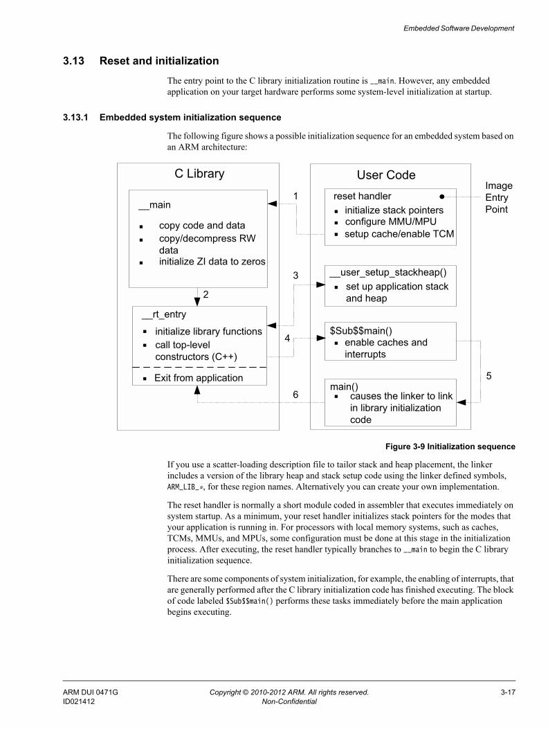
Embedded Software Development
3.13 Reset and initializationThe entry point to the C library initialization routine is __main. However, any embedded application on your target hardware performs some system-level initialization at startup.
3.13.1 Embedded system initialization sequence
The following figure shows a possible initialization sequence for an embedded system based on an ARM architecture:
Figure 3-9 Initialization sequence
If you use a scatter-loading description file to tailor stack and heap placement, the linker includes a version of the library heap and stack setup code using the linker defined symbols, ARM_LIB_*, for these region names. Alternatively you can create your own implementation.
The reset handler is normally a short module coded in assembler that executes immediately on system startup. As a minimum, your reset handler initializes stack pointers for the modes that your application is running in. For processors with local memory systems, such as caches, TCMs, MMUs, and MPUs, some configuration must be done at this stage in the initialization process. After executing, the reset handler typically branches to __main to begin the C library initialization sequence.
There are some components of system initialization, for example, the enabling of interrupts, that are generally performed after the C library initialization code has finished executing. The block of code labeled $Sub$$main() performs these tasks immediately before the main application begins executing.
C Library User Code
__user_setup_stackheap()set up application stack and heap
main()causes the linker to link in library initialization code
$Sub$$main()enable caches and interrupts
reset handlerinitialize stack pointersconfigure MMU/MPUsetup cache/enable TCM
1
2
3
4
5
6
__rt_entry
initialize library functionscall top-level constructors (C++)
Exit from application
..
. .
.
.
...__main
copy code and datacopy/decompress RW data. initialize ZI data to zeros
..Image Entry Point
ARM DUI 0471G Copyright © 2010-2012 ARM. All rights reserved. 3-17ID021412 Non-Confidential

Embedded Software Development
3.13.2 See also
Other information Using ARM C and C++ Libraries and Floating Point Support:• Using $Super$$ and $Sub$$ to patch symbol definitions on page 7-29.Linker Reference:• Specifying stack and heap using the scatter file on page 8-12.
ARM DUI 0471G Copyright © 2010-2012 ARM. All rights reserved. 3-18ID021412 Non-Confidential

Embedded Software Development
3.14 The vector tableAll ARM systems have a vector table. The vector table does not form part of the initialization sequence, but it must be present for any exception to be serviced. It must be placed at a specific address, usually 0x0. To do this you can use the scatter-loading +FIRST directive, as shown in the following example.
Example 3-4 Placing the vector table at a specific address
ROM_LOAD 0x0000 0x4000{ ROM_EXEC 0x0000 0x4000 ; root region { vectors.o (Vect, +FIRST) ; Vector table * (InRoot$$Sections) ; All library sections that must be in a ; root region, for example, __main.o, ; __scatter*.o, __dc*.o, and * Region$$Table } RAM 0x10000 0x8000 { * (+RO, +RW, +ZI) ; all other sections }}
The vector table for the microcontroller profiles is very different to most ARM architectures.
3.14.1 See also
Reference • Vector table for ARMv6 and earlier, ARMv7-A and ARMv7-R profiles on page 6-6• Vector table for ARMv6-M and ARMv7-M profiles on page 6-39• Writing the exception table for ARMv6-M and ARMv7-M profiles on page 6-41.
ARM DUI 0471G Copyright © 2010-2012 ARM. All rights reserved. 3-19ID021412 Non-Confidential

Embedded Software Development
3.15 ROM and RAM remapping
Note This information does not apply to ARMv6-M and ARMv7-M profiles.
You must consider what sort of memory your system has at address 0x0, the address of the first instruction executed.
Note This information assumes that an ARM processor begins fetching instructions at 0x0. This is the standard behavior for systems based on ARM processors. However, some ARM processors can be configured to begin fetching instructions from 0xFFFF0000.
There has to be a valid instruction at 0x0 at startup, so you must have nonvolatile memory located at 0x0 at the moment of power-on reset. One way to achieve this is to have ROM located at 0x0. However, there are some drawbacks to this configuration.
3.15.1 Example ROM/RAM remapping
The following example shows a solution implementing ROM/RAM remapping after reset. The constants shown in this example are specific to the Versatile board, but the same method is applicable to any platform that implements remapping in a similar way. Scatter-loading description files must describe the memory map after remapping.
Example 3-5 ROM/RAM remapping
; System memory locationsVersatile_ctl_reg EQU 0x101E0000 ; Address of control registerDEVCHIP_Remap_bit EQU 0x100 ; Bit 8 is remap bit of control register ENTRY; Code execution starts here on reset; On reset, an alias of ROM is at 0x0, so jump to 'real' ROM. LDR pc, =Instruct_2Instruct_2 ; Remap by setting remap bit of the control register; Clear the DEVCHIP_Remap_bit by writing 1 to bit 8 of the control register LDR R1, =Versatile_ctl_reg LDR R0, [R1] ORR R0, R0, #DEVCHIP_Remap_bit STR R0, [R1]; RAM is now at 0x0.; The exception vectors must be copied from ROM to RAM; The copying is done later by the C library code inside __main; Reset_Handler follows on from here
ARM DUI 0471G Copyright © 2010-2012 ARM. All rights reserved. 3-20ID021412 Non-Confidential

Embedded Software Development
3.16 Local memory setup considerationsMany ARM processors have on-chip memory management systems, such as MMUs or MPUs. These devices are normally set up and enabled during system startup. Therefore, the initialization sequence of processors with local memory systems requires special consideration.
The C library initialization code in __main is responsible for setting up the execution time memory map of the image. Therefore, the run-time memory view of the processor must be set up before branching to __main. This means that any MMU or MPU must be set up and enabled in the reset handler.
TCMs must also be enabled before branching to __main, normally before MMU/MPU setup, because you generally want to scatter-load code and data into TCMs. You must be careful that you do not have to access memory that is masked by the TCMs when they are enabled.
You also risk problems with cache coherency if caches are enabled before branching to __main. Code in __main copies code regions from their load address to their execution address, essentially treating instructions as data. As a result, some instructions can be cached in the data cache, in which case they are not visible to the instruction path.
To avoid these coherency problems, enable caches after the C library initialization sequence finishes executing.
ARM DUI 0471G Copyright © 2010-2012 ARM. All rights reserved. 3-21ID021412 Non-Confidential

Embedded Software Development
3.17 Stack pointer initializationAs a minimum, your reset handler must assign initial values to the stack pointers of any execution modes that are used by your application.
3.17.1 Example stack pointer initialization
In this example, the stacks are located at stack_base:
Example 3-6 Initializing stack pointers
; ***************************************************************; This example does not apply to ARMv6-M and ARMv7-M profiles; ***************************************************************Len_FIQ_Stack EQU 256Len_IRQ_Stack EQU 256stack_base DCD 0x18000;Reset_Handler
; stack_base could be defined above, or located in a scatter fileLDR R0, stack_base ;; Enter each mode in turn and set up the stack pointerMSR CPSR_c, #Mode_FIQ:OR:I_Bit:OR:F_Bit ; Interrupts disabledMOV sp, R0SUB R0, R0, #Len_FIQ_StackMSR CPSR_c, #Mode_IRQ:OR:I_Bit:OR:F_Bit ; Interrupts disabledMOV sp, R0SUB R0, R0, #Len_IRQ_StackMSR CPSR_c, #Mode_SVC:OR:I_Bit:OR:F_Bit ; Interrupts disabledMOV sp, R0; Leave processor in SVC mode
The stack_base symbol can be a hard-coded address, or it can be defined in a separate assembler source file and located by a scatter-loading description file.
The example allocates 256 bytes of stack for Fast Interrupt Request (FIQ) and Interrupt Request (IRQ) mode, but you can do the same for any other execution mode. To set up the stack pointers, enter each mode with interrupts disabled, and assign the appropriate value to the stack pointer.
The stack pointer value set up in the reset handler is automatically passed as a parameter to __user_initial_stackheap() by C library initialization code. Therefore, this value must not be modified by __user_initial_stackheap().
3.17.2 See also
Tasks Using the Linker:• Specifying stack and heap using the scatter file on page 8-12.
ARM DUI 0471G Copyright © 2010-2012 ARM. All rights reserved. 3-22ID021412 Non-Confidential
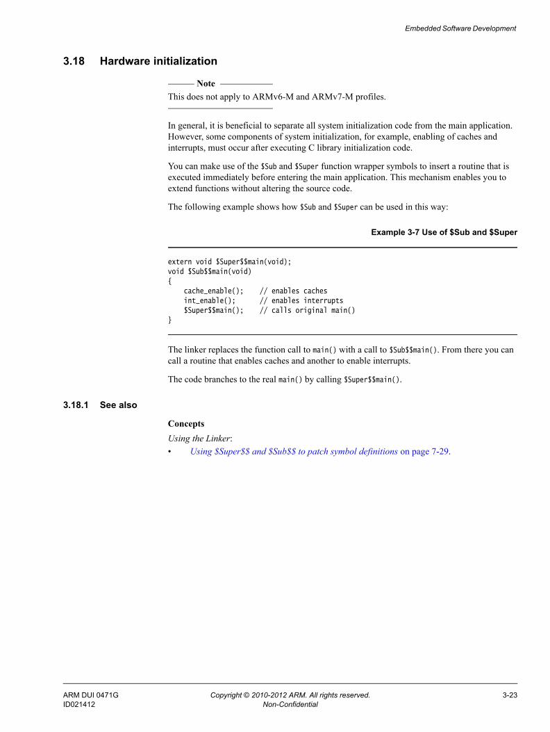
Embedded Software Development
3.18 Hardware initialization
Note This does not apply to ARMv6-M and ARMv7-M profiles.
In general, it is beneficial to separate all system initialization code from the main application. However, some components of system initialization, for example, enabling of caches and interrupts, must occur after executing C library initialization code.
You can make use of the $Sub and $Super function wrapper symbols to insert a routine that is executed immediately before entering the main application. This mechanism enables you to extend functions without altering the source code.
The following example shows how $Sub and $Super can be used in this way:
Example 3-7 Use of $Sub and $Super
extern void $Super$$main(void);void $Sub$$main(void){ cache_enable(); // enables caches int_enable(); // enables interrupts $Super$$main(); // calls original main()}
The linker replaces the function call to main() with a call to $Sub$$main(). From there you can call a routine that enables caches and another to enable interrupts.
The code branches to the real main() by calling $Super$$main().
3.18.1 See also
Concepts Using the Linker:• Using $Super$$ and $Sub$$ to patch symbol definitions on page 7-29.
ARM DUI 0471G Copyright © 2010-2012 ARM. All rights reserved. 3-23ID021412 Non-Confidential

Embedded Software Development
3.19 Execution mode considerations
Note This does not apply to ARMv6-M and ARMv7-M profiles.
You must consider the mode in which the main application is to run. Your choice affects how you implement system initialization.
Much of the functionality that you are likely to implement at startup, both in the reset handler and $Sub$$main, can only be done while executing in privileged modes, for example, on-chip memory manipulation, and enabling interrupts.
If you want to run your application in a privileged mode, this is not an issue. Ensure that you change to the appropriate mode before exiting your reset handler.
If you want to run your application in User mode, however, you can only change to User mode after completing the necessary tasks in a privileged mode. The most likely place to do this is in $Sub$$main().
Note The C library initialization code must use the same stack as the application. If you need to use a non-User mode in $Sub$$main and User mode in the application, you must exit your reset handler in System mode, which uses the User mode stack pointer.
ARM DUI 0471G Copyright © 2010-2012 ARM. All rights reserved. 3-24ID021412 Non-Confidential

Embedded Software Development
3.20 Target hardware and the memory mapThe previous sections describe the placement of code and data in a scatter-loading description file. However, the location of target hardware peripherals and the stack and heap limits are assumed to be hard-coded in source or header files. It is better to locate all information about the memory map of a target in your description file, and remove all references to absolute addresses from your source code.
Conventionally, addresses of peripheral registers are hard-coded in project source or header files. You can also declare structures that map on to peripheral registers, and place these structures in the scatter-loading description file.
For example, if a target has a timer peripheral with two memory mapped 32-bit registers, a C structure that maps to these registers is:
Example 3-8 Mapping to a peripheral register
__attribute__ ((zero_init)) struct{ volatile unsigned ctrl; /* timer control */ volatile unsigned tmr; /* timer value */} timer_regs;
To place this structure at a specific address in the memory map, you can create an execution region containing the module that defines the structure. The following example shows an execution region called TIMER that locates the timer_regs structure at 0x40000000:
Example 3-9 Placing the mapped structure
ROM_LOAD 0x24000000 0x04000000{; ...TIMER 0x40000000 UNINIT { timer_regs.o (+ZI) } ; ...}
It is important that the contents of these registers are not zero initialized during application startup, because this is likely to change the state of your system. Marking an execution region with the UNINIT attribute prevents ZI data in that region from being zero initialized by __main.
ARM DUI 0471G Copyright © 2010-2012 ARM. All rights reserved. 3-25ID021412 Non-Confidential
Chapter 4 Mixing C, C++, and Assembly Language
The following topics describe how to write a mixture of C, C++, and assembly language code for the ARM architecture:• Instruction intrinsics, inline and embedded assembler on page 4-2• Access to C global variables from assembly code on page 4-4• Including system C header files from C++ on page 4-5• Including your own C header files from C++ on page 4-6• Mixed-language programming on page 4-7• Rules for calling between C, C++, and assembly language on page 4-8• Rules for calling C++ functions from C and assembly language on page 4-9• Information specific to C++ on page 4-10• Examples of calling between languages on page 4-11• Calls to assembly language from C on page 4-12• Calls to C from assembly language on page 4-13• Calls to C from C++ on page 4-14• Calls to assembly language from C++ on page 4-15• Calls to C++ from C on page 4-16• Calls to C++ from assembly language on page 4-17• Calls to C++ from C or assembly language on page 4-18• Passing a reference between C and C++ on page 4-20.
ARM DUI 0471G Copyright © 2010-2012 ARM. All rights reserved. 4-1ID021412 Non-Confidential

Mixing C, C++, and Assembly Language
4.1 Instruction intrinsics, inline and embedded assemblerInstruction intrinsics, inline and embedded assembler are built into the compiler to enable the use of target processor features that cannot normally be accessed directly from C or C++. For example:• saturating arithmetic• custom coprocessors• the Program Status Register (PSR).
Instruction intrinsics Instruction intrinsics provide a way of easily incorporating target processor features in C and C++ source code without resorting to complex implementations in assembly language. They have the appearance of a function call in C or C++, but are replaced during compilation by assembly language instructions.
Note Instruction intrinsics are specific to the ARM instruction set and are therefore not
portable to other architecture.
Inline assembler The inline assembler supports interworking with C and C++. Any register operand can be an arbitrary C or C++ expression. The inline assembler also expands complex instructions and optimizes the assembly language code.
Note The output object code might not correspond exactly to your input because of
compiler optimization.
Embedded assembler The embedded assembler enables you to use the full ARM assembler instruction set, including assembler directives. Embedded assembly code is assembled separately from the C and C++ code. A compiled object is produced that is then combined with the object from the compilation of the C and C++ source.
The following table summarizes the main differences between instruction intrinsics, inline and embedded assembler.
Table 4-1 Differences
Feature Instruction Intrinsics Inline assembler Embedded assembler
Instruction set ARM and Thumb. ARM only. ARM and Thumb.
ARM assembler directives None supported. None supported. All supported.
C/C++ expressions Full C/C++ expressions. Full C/C++ expressions. Constant expressions only.
Optimization of assembly code Full optimization. Full optimization. No optimization.
Inlining Automatically inlined. Automatically inlined. Can be inlined by linker if it is the right size and linker inlining is enabled.
ARM DUI 0471G Copyright © 2010-2012 ARM. All rights reserved. 4-2ID021412 Non-Confidential

Mixing C, C++, and Assembly Language
4.1.1 See also
Tasks Using the Compiler:• Chapter 8 Using the Inline and Embedded Assemblers of the ARM Compiler.
Concepts Using the Compiler:• Compiler intrinsics on page 5-3Using the Assembler:• Saturating instructions on page 3-97.
Reference Compiler Reference:• Instruction intrinsics on page 5-117.
Register access Physical registers, including PC, LR and SP.
Virtual registers except PC, LR and SP.
Physical registers, including PC, LR and SP.
Return instructions Generated automatically. Generated automatically. BX, BXJ, and BLX instructions are not supported.
You must add them in your code.
BKPT instruction Supported. Not supported. Supported.
Table 4-1 Differences (continued)
Feature Instruction Intrinsics Inline assembler Embedded assembler
ARM DUI 0471G Copyright © 2010-2012 ARM. All rights reserved. 4-3ID021412 Non-Confidential

Mixing C, C++, and Assembly Language
4.2 Access to C global variables from assembly codeGlobal variables can only be accessed indirectly, through their address. To access a global variable, use the IMPORT directive to do the import and then load the address into a register. You can access the global variable with load and store instructions, depending on its type.
For unsigned variables, for example, use:• LDRB/STRB for char• LDRH/STRH for short• LDR/STR for int.
For signed variables, use the equivalent signed instruction, such as LDRSB and LDRSH.
Small structures of less than eight words can be accessed as a whole using the LDM and STM instructions. Individual members of structures can be accessed by a load or store instruction of the appropriate type. You must know the offset of a member from the start of the structure in order to access it.
The following example loads the address of the integer global variable globvar into R1, loads the value contained in that address into R0, adds 2 to it, then stores the new value back into globvar.
Example 4-1 Accessing global variables
PRESERVE8 AREA globals,CODE,READONLY EXPORT asmsubroutine IMPORT globvarasmsubroutine LDR R1, =globvar ; read address of globvar into R1
LDR R0, [R1] ; load value of globvar ADD R0, R0, #2 STR R0, [R1] ; store new value into globvar BX lr END
4.2.1 See also
Concepts Using the Assembler:• Chapter 3 ARM and Thumb Instructions.
ARM DUI 0471G Copyright © 2010-2012 ARM. All rights reserved. 4-4ID021412 Non-Confidential

Mixing C, C++, and Assembly Language
4.3 Including system C header files from C++C header files must be wrapped in extern "C" directives before they are included from C++. Standard system C header files already contain the appropriate extern "C" directives so you do not have to take any special steps to include such files. Different #include syntaxes determine what namespace to use and therefore the type of access you have.
For example:
#include <stdio.h>int main(){ ... // C++ code return 0;}
If you include headers using this syntax, all library names are placed in the global namespace.
The C++ standard specifies that the functionality of the C header files is available through C++ specific header files. These files are installed in install_directory\include, together with the standard C header files, and can be referenced in the usual way. For example:
#include <cstdio>
In ARM C++, these headers #include the C headers. If you include headers using this syntax, all C++ standard library names are defined in the namespace std, including the C library names. This means that you must qualify all the library names by using one of the following methods:
• specify the standard namespace, for example:std::printf("example\n");
• use the C++ keyword using to import a name to the global namespace:using namespace std;printf("example\n");
• use the compiler option --using_std.
4.3.1 See also
Reference Compiler Reference:• --using_std, --no_using_std on page 3-211.
ARM DUI 0471G Copyright © 2010-2012 ARM. All rights reserved. 4-5ID021412 Non-Confidential

Mixing C, C++, and Assembly Language
4.4 Including your own C header files from C++To include your own C header files, you must wrap the #include directive in an extern "C" statement. You can do this in the following ways:• when you #include the file, as shown in the following example• by adding the extern "C" statement to the header file, as shown in the Directive in file
header example.
Example 4-2 Directive before include file
// C++ codeextern "C" {#include "my-header1.h"#include "my-header2.h"}int main(){ // ... return 0;}
Example 4-3 Directive in file header
/* C header file */#ifdef __cplusplus /* Insert start of extern C construct */extern "C" {#endif/* Body of header file */#ifdef __cplusplus /* Insert end of extern C construct. */} /* The C header file can now be */#endif /* included in either C or C++ code. */
ARM DUI 0471G Copyright © 2010-2012 ARM. All rights reserved. 4-6ID021412 Non-Confidential

Mixing C, C++, and Assembly Language
4.5 Mixed-language programmingYou can mix calls between C and C++ and assembly language routines provided you comply with the Procedure Call Standard for the ARM Architecture (AAPCS).
Note The information in this section is implementation dependent and might change in future releases.
The embedded assembler and compliance with the Base Standard Application Binary Interface for the ARM Architecture (BSABI) make mixed language programming easier to implement. These assist you with:• name mangling, using the __cpp keyword• the way the implicit this parameter is passed• the way virtual functions are called• the representation of references• the layout of C++ class types that have base classes or virtual member functions• the passing of class objects that are not Plain Old Data Structures (PODS).
4.5.1 See also
Concepts • Rules for calling between C, C++, and assembly language on page 4-8• Rules for calling C++ functions from C and assembly language on page 4-9.Using the Compiler:• The compiler on page 2-2.
Other information • Base Standard Application Binary Interface for the ARM Architecture,
http://infocenter.arm.com/help/topic/com.arm.doc.ihi0036-/index.html
• Procedure Call Standard for the ARM Architecture, http://infocenter.arm.com/help/topic/com.arm.doc.ihi0042-/index.html.
ARM DUI 0471G Copyright © 2010-2012 ARM. All rights reserved. 4-7ID021412 Non-Confidential

Mixing C, C++, and Assembly Language
4.6 Rules for calling between C, C++, and assembly languageThe following general rules apply to calling between C, C++, and assembly language:
• Use C calling conventions.
• C header files must be wrapped in extern "C" directives before they are included from C++.
• In C++, nonmember functions can be declared as extern "C" to specify that they have C linkage. In this release of ARM Compiler toolchain, having C linkage means that the symbol defining the function is not mangled. C linkage can be used to implement a function in one language and call it from another.
Note Functions that are declared extern "C" cannot be overloaded.
• Assembly language modules must conform to the appropriate AAPCS standard for the memory model used by the application.
4.6.1 See also
Concepts • Mixed-language programming on page 4-7• Rules for calling C++ functions from C and assembly language on page 4-9.Using the Compiler:• The compiler on page 2-2.
ARM DUI 0471G Copyright © 2010-2012 ARM. All rights reserved. 4-8ID021412 Non-Confidential
Mixing C, C++, and Assembly Language
4.7 Rules for calling C++ functions from C and assembly languageThe following rules apply to calling C++ functions from C and assembly language:
• To call a global C++ function, declare it extern "C" to give it C linkage.
• Member functions, both static and non static, always have mangled names. Using the __cpp keyword of the embedded assembler means that you do not have to find the mangled names manually.
• C++ inline functions cannot be called from C unless you ensure that the C++ compiler generates an out-of-line copy of the function. For example, taking the address of the function results in an out-of-line copy.
• Nonstatic member functions receive the implicit this parameter as a first argument in R0, or as a second argument in R1 if the function returns a non int-like structure. Static member functions do not receive an implicit this parameter.
4.7.1 See also
Concepts • Mixed-language programming on page 4-7• Rules for calling between C, C++, and assembly language on page 4-8.Using the Compiler:• The compiler on page 2-2.
ARM DUI 0471G Copyright © 2010-2012 ARM. All rights reserved. 4-9ID021412 Non-Confidential

Mixing C, C++, and Assembly Language
4.8 Information specific to C++The following information applies specifically to C++.
4.8.1 C++ calling conventions
ARM C++ uses the same calling conventions as ARM C with one exception:
• Nonstatic member functions are called with the implicit this parameter as the first argument, or as the second argument if the called function returns a non int-like struct. This might change in future implementations.
4.8.2 C++ data types
ARM C++ uses the same data types as ARM C with the following exceptions and additions:
• C++ objects of type struct or class have the same layout that is expected from ARM C if they have no base classes or virtual functions. If such a struct has neither a user-defined copy assignment operator nor a user-defined destructor, it is a plain old data structure.
• References are represented as pointers.
• No distinction is made between pointers to C functions and pointers to C++ nonmember functions.
4.8.3 Symbol name mangling
The linker unmangles symbol names in messages.
C names must be declared as extern "C" in C++ programs. This is done already for the ARM ISO C headers.
4.8.4 See also
Reference • Mixed-language programming on page 4-7.
ARM DUI 0471G Copyright © 2010-2012 ARM. All rights reserved. 4-10ID021412 Non-Confidential

Mixing C, C++, and Assembly Language
4.9 Examples of calling between languagesThe following code examples demonstrate how to mix language calls: • Calls to assembly language from C on page 4-12• Calls to C from assembly language on page 4-13• Calls to C from C++ on page 4-14• Calls to assembly language from C++ on page 4-15• Calls to C++ from C on page 4-16• Calls to C++ from assembly language on page 4-17• Calls to C++ from C or assembly language on page 4-18• Passing a reference between C and C++ on page 4-20.
ARM DUI 0471G Copyright © 2010-2012 ARM. All rights reserved. 4-11ID021412 Non-Confidential
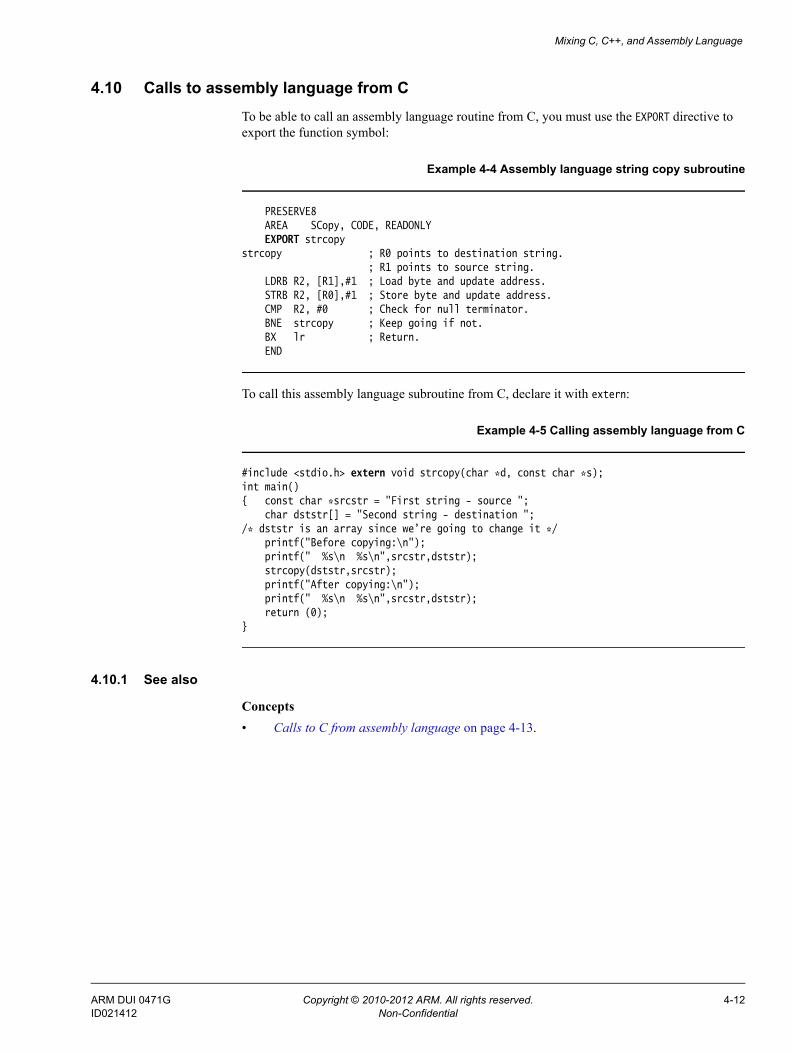
Mixing C, C++, and Assembly Language
4.10 Calls to assembly language from CTo be able to call an assembly language routine from C, you must use the EXPORT directive to export the function symbol:
Example 4-4 Assembly language string copy subroutine
PRESERVE8 AREA SCopy, CODE, READONLY EXPORT strcopystrcopy ; R0 points to destination string. ; R1 points to source string. LDRB R2, [R1],#1 ; Load byte and update address. STRB R2, [R0],#1 ; Store byte and update address. CMP R2, #0 ; Check for null terminator. BNE strcopy ; Keep going if not. BX lr ; Return. END
To call this assembly language subroutine from C, declare it with extern:
Example 4-5 Calling assembly language from C
#include <stdio.h> extern void strcopy(char *d, const char *s);int main(){ const char *srcstr = "First string - source "; char dststr[] = "Second string - destination ";/* dststr is an array since we’re going to change it */ printf("Before copying:\n"); printf(" %s\n %s\n",srcstr,dststr); strcopy(dststr,srcstr); printf("After copying:\n"); printf(" %s\n %s\n",srcstr,dststr); return (0);}
4.10.1 See also
Concepts • Calls to C from assembly language on page 4-13.
ARM DUI 0471G Copyright © 2010-2012 ARM. All rights reserved. 4-12ID021412 Non-Confidential
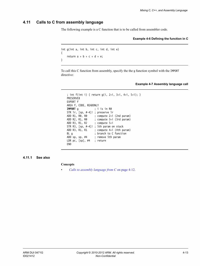
Mixing C, C++, and Assembly Language
4.11 Calls to C from assembly languageThe following example is a C function that is to be called from assembler code.
Example 4-6 Defining the function in C
int g(int a, int b, int c, int d, int e) { return a + b + c + d + e;}
To call this C function from assembly, specify the the g function symbol with the IMPORT directive:
Example 4-7 Assembly language call
; int f(int i) { return g(i, 2*i, 3*i, 4*i, 5*i); } PRESERVE8 EXPORT f AREA f, CODE, READONLY IMPORT g ; i is in R0 STR lr, [sp, #-4]! ; preserve lr ADD R1, R0, R0 ; compute 2*i (2nd param) ADD R2, R1, R0 ; compute 3*i (3rd param) ADD R3, R1, R2 ; compute 5*i STR R3, [sp, #-4]! ; 5th param on stack ADD R3, R1, R1 ; compute 4*i (4th param) BL g ; branch to C function ADD sp, sp, #4 ; remove 5th param LDR pc, [sp], #4 ; return END
4.11.1 See also
Concepts • Calls to assembly language from C on page 4-12.
ARM DUI 0471G Copyright © 2010-2012 ARM. All rights reserved. 4-13ID021412 Non-Confidential

Mixing C, C++, and Assembly Language
4.12 Calls to C from C++The following example is a C function that is to be called from C++:
Example 4-8 Defining the function in C
struct S { int i;};void cfunc(struct S *p) {/* the definition of the C function to be called from C++ */ p->i += 5;}
To call this C function from C++, declare it with extern "C":
Example 4-9 Calling a C function from C++
struct S { // has no base classes // or virtual functions S(int s) : i(s) { } int i;}; extern "C" void cfunc(S *); // declare the C function to be called from C++int f(){ S s(2); // initialize 's' cfunc(&s); // call 'cfunc' so it can change 's' return s.i * 3;}
4.12.1 See also
Concepts • Calls to assembly language from C++ on page 4-15• Calls to C++ from C on page 4-16.
ARM DUI 0471G Copyright © 2010-2012 ARM. All rights reserved. 4-14ID021412 Non-Confidential

Mixing C, C++, and Assembly Language
4.13 Calls to assembly language from C++To be able to call an assembly language routine from C++, you must use the EXPORT directive to export the function symbol:
Example 4-10 Defining the assembly language function
PRESERVE8 AREA Asm, CODE EXPORT asmfuncasmfunc ; the definition of the Asm LDR R1, [R0] ; function to be called from C++ ADD R1, R1, #5 STR R1, [R0] BX lr END
To call the assembly language routine from C++, declare it with extern "C":
Example 4-11 Calling assembly language from C++
struct S { // has no base classes // or virtual functions S(int s) : i(s) { } int i;}; extern "C" void asmfunc(S *); // declare the Asm function // to be calledint f() { S s(2); // initialize 's' asmfunc(&s); // call 'asmfunc' so it // can change 's' return s.i * 3;}
4.13.1 See also
Concepts • Calls to C from C++ on page 4-14.
ARM DUI 0471G Copyright © 2010-2012 ARM. All rights reserved. 4-15ID021412 Non-Confidential

Mixing C, C++, and Assembly Language
4.14 Calls to C++ from CTo call a C++ function from C, define the C++ function with extern "C":
Example 4-12 Defining the C++ function to be called from C
struct S { // has no base classes or virtual functions S(int s) : i(s) { } int i;}; extern "C" void cppfunc(S *p) { // Definition of the C++ function to be called from C.// The function is written in C++, only the linkage is C. p->i += 5;}
In C, declare the C++ function with extern:
Example 4-13 Declaring and calling the function in C
struct S { int i;}; extern void cppfunc(struct S *p);/* Declaration of the C++ function to be called from C */int f(void) { struct S s; s.i = 2; /* initialize 's' */ cppfunc(&s); /* call 'cppfunc' so it */ /* can change 's' */ return s.i * 3;}
4.14.1 See also
Concepts • Calls to assembly language from C on page 4-12.
ARM DUI 0471G Copyright © 2010-2012 ARM. All rights reserved. 4-16ID021412 Non-Confidential

Mixing C, C++, and Assembly Language
4.15 Calls to C++ from assembly languageTo be able to call a C++ function from assembly, use the extern "C" declaration:
Example 4-14 Defining the function to be called in C++
struct S { // has no base classes or virtual functions S(int s) : i(s) { } int i;}; extern "C" void cppfunc(S * p) {// Definition of the C++ function to be called from ASM.// The body is C++, only the linkage is C. p->i += 5;}
In ARM assembly language, import the name of the C++ function and use a Branch with Link (BL) instruction to call it:
Example 4-15 Defining assembly language function
AREA Asm, CODE IMPORT cppfunc ; import the name of the C++ ; function to be called from Asm EXPORT ff STMFD sp!,{lr} MOV R0,#2 STR R0,[sp,#-4]! ; initialize struct MOV R0,sp ; argument is pointer to struct BL cppfunc ; call 'cppfunc' so it can change the struct
LDR R0, [sp], #4 ADD R0, R0, R0,LSL #1 LDMFD sp!,{pc} END
4.15.1 See also
Concepts • Calls to assembly language from C++ on page 4-15.
ARM DUI 0471G Copyright © 2010-2012 ARM. All rights reserved. 4-17ID021412 Non-Confidential

Mixing C, C++, and Assembly Language
4.16 Calls to C++ from C or assembly languageThis example shows how to call a non static, non virtual C++ member function from C.
Example 4-16 Calling a C++ member function
struct T { T(int i) : t(i) { } int t; int f(int i);};int T::f(int i) { return i + t; } // Definition of the C++ function to be called from C.extern "C" int cfunc(T*); // Declaration of the C function to be called from C++.int f() { T t(5); // create an object of type T return cfunc(&t);}
Use the assembler output from the compiler to locate the mangled name of the function. For example, if this code is in the file test.cpp, enter the command:
armcc -c --cpp --asm test.cpp
This produces the assembler file test.s containing:
... AREA ||.text||, CODE, READONLY, ALIGN=2
_Z1fv PROC PUSH {r3,lr} MOV r0,#5 STR r0,[sp,#0] MOV r0,sp BL cfunc POP {r3,pc} ENDP
_ZN1T1fEi PROC LDR r0,[r0,#0] ADD r0,r0,r1 BX lr ENDP...
You define the C function using the mangled name _ZN1T1fEi as follows:
Example 4-17 Defining the C function
struct T;extern int _ZN1T1fEi(struct T*, int); /* the mangled name of the C++ */ /* function to be called */int cfunc(struct T* t) { /* Definition of the C function to be called from C++. */ return 3 * _ZN1T1fEi(t, 2); /* like '3 * t->f(2)' */}
ARM DUI 0471G Copyright © 2010-2012 ARM. All rights reserved. 4-18ID021412 Non-Confidential

Mixing C, C++, and Assembly Language
To implement the function in assembly language:
Example 4-18 Implementing the function in assembly language
EXPORT cfunc AREA foo, CODE IMPORT _ZN1T1fEicfunc STMFD sp!,{lr} ; R0 already contains the object pointer MOV R1, #2 BL _ZN1T1fEi ADD R0, R0, R0, LSL #1 ; multiply by 3 LDMFD sp!,{pc} END
Alternatively, you can implement the call to a C++ member function and the function in assembly language using embedded assembly. In this example, use the __cpp keyword to reference the function. Therefore, you do not have to know the mangled name of the function.
Example 4-19 Implementing the function in embedded assembly
struct T { T(int i) : t(i) { } int t; int f(int i);};int T::f(int i) { return i + t; }// Definition of asm function called from C++__asm int asm_func(T*) { STMFD sp!, {lr} MOV R1, #2; BL __cpp(T::f); ADD R0, R0, R0, LSL #1 ; multiply by 3 LDMFD sp!, {pc}}int f() { T t(5); // create an object of type T return asm_func(&t);}
4.16.1 See also
Concepts • Calls to assembly language from C on page 4-12• Calls to assembly language from C++ on page 4-15• Calls to C from assembly language on page 4-13• Calls to C++ from assembly language on page 4-17.
Reference • ARM C and C++ Libraries and Floating Point Support Reference.
ARM DUI 0471G Copyright © 2010-2012 ARM. All rights reserved. 4-19ID021412 Non-Confidential

Mixing C, C++, and Assembly Language
4.17 Passing a reference between C and C++To pass references between C and C++, use the extern "C" declaration:
Example 4-20 Defining the C++ function
extern "C" int cfunc(const int&); // Declaration of the C function to be called from C++ extern "C"int cppfunc(const int& r) {// Definition of the C++ function to be called from C. return 7 * r;}int f() { int i = 3; return cfunc(i); // passes a pointer to 'i'}
In the C function, declare the C++ reference with extern:
Example 4-21 Defining the C function
extern int cppfunc(const int*); /* declaration of the C++ function to be called from C */int cfunc(const int *p) { /* definition of the C function to be called from C++ */ int k = *p + 4; return cppfunc(&k);}
ARM DUI 0471G Copyright © 2010-2012 ARM. All rights reserved. 4-20ID021412 Non-Confidential

Chapter 5 Interworking ARM and Thumb
The following topics describe how to change between ARM state and Thumb state when writing code for processors that implement the ARM and Thumb instruction sets:• About interworking on page 5-2• When to use interworking on page 5-3• Assembly language interworking on page 5-4• C and C++ interworking on page 5-5• Pointers to functions in Thumb state on page 5-6• Using two versions of the same function on page 5-7• Assembly language interworking example on page 5-8• Interworking using veneers on page 5-10• C and C++ language interworking on page 5-12• C, C++, and assembly language interworking using veneers on page 5-14.
Note These topics do not apply to ARMv6-M and ARMv7-M.
ARM DUI 0471G Copyright © 2010-2012 ARM. All rights reserved. 5-1ID021412 Non-Confidential

Interworking ARM and Thumb
5.1 About interworkingInterworking enables you to mix ARM and Thumb code so that:• ARM routines can return to a Thumb state caller• Thumb routines can return to an ARM state caller.
This means that, if you compile or assemble code for interworking, your code can call a routine in a different module without considering which instruction set it uses. The compiler and assembler both use the --apcs=/interwork command-line option to enable interworking.
You can freely mix code compiled or assembled for ARM and Thumb, provided that the code conforms to the AAPCS.
An error is generated if the linker detects:
• a direct ARM or Thumb interworking call where the callee routine is not built for interworking
• assembly language source files using incompatible AAPCS options.
The ARM linker detects when an interworking function is being called from a different state. Call and return instructions are changed, and small code segments called veneers, are inserted to change processor state where necessary.
The ARM architecture v5T and later provide methods to change processor state without using any extra instructions. There is almost no cost associated with interworking on ARMv5T and later processors.
Note Compiling for ARMv5T and later architectures, automatically assumes interworking and always produces code that is interworking safe. However, assembly code built for ARMv5T does not imply interworking, so you must build assembly code with the --apcs=/interwork assembler option.
5.1.1 See also
Reference Assembler Reference:• --apcs=qualifier…qualifier on page 2-5.Linker Reference:• Overview of veneers on page 4-26.
Other information • Procedure Call Standard for the ARM Architecture,
http://infocenter.arm.com/help/topic/com.arm.doc.ihi0042-/index.html.
ARM DUI 0471G Copyright © 2010-2012 ARM. All rights reserved. 5-2ID021412 Non-Confidential

Interworking ARM and Thumb
5.2 When to use interworkingWhen you write code for an ARM processor that supports Thumb instructions, you probably build most of your application to run in Thumb state. This gives the best code density. With 8-bit or 16-bit wide memory, it also gives the best performance. However, you might want parts of your application to run in ARM state for reasons such as:
Speed Some parts of an application might be speed critical. These sections might be more efficient running in ARM state than in Thumb state. Some systems include a small amount of fast 32-bit memory. ARM code can be run from this without the overhead of fetching each instruction from 8-bit or 16-bit memory.
Functionality Thumb instructions are less flexible than their equivalent ARM instructions. Some operations are not possible in Thumb state. A state change to ARM is required to carry out the following operations:• accesses to CPSR to enable or disable interrupts, and to change mode.• accesses to coprocessors• execution of Digital Signal Processor (DSP) math instructions that can not
be performed in C language.
Exception handling The processor automatically enters ARM state when a processor exception occurs. This means that the first part of an exception handler must be coded with ARM instructions, even if it reenters Thumb state to carry out the main processing of the exception. At the end of such processing, the processor must be returned to ARM state to return from the handler to the main application.
Standalone Thumb programs An ARM processor that supports Thumb instructions always starts in ARM state. To run simple Thumb assembly language programs, add an ARM header that carries out a state change to Thumb state and then calls the main Thumb routine.
Note Changing to ARM state for speed or functionality reasons is mainly a concern on processors that support Thumb without the 32-bit Thumb instruction set. The 32-bit Thumb instruction set provides almost exactly the same functionality as the ARM instruction set.
5.2.1 See also
Concepts • Assembly language interworking on page 5-4.
Reference Assembler Reference:• CPS on page 3-141.
ARM DUI 0471G Copyright © 2010-2012 ARM. All rights reserved. 5-3ID021412 Non-Confidential

Interworking ARM and Thumb
5.3 Assembly language interworkingThe --apcs=/interwork command-line option enables the ARM assembler to assemble code that can be called from another processor state:
armasm --thumb --apcs=/interworkarmasm --arm --apcs=/interwork
In an assembly language source file, you can have several areas. These correspond to ARM Executable and Linkable Format (ELF) sections. Each area can contain ARM instructions, Thumb instructions, or both.
You can use the linker to fix up calls to, and returns from, routines that use a different instruction set from the caller. To do this, use BL to call the routine
If you prefer, you can write your code to make the instruction set changes explicitly. In some circumstances you can write smaller or faster code by doing this. You can use BX, BLX, LDR, LDM, and POP instructions to perform the processor state changes.
The ARM assembler can assemble both Thumb code and ARM code. By default, it assembles ARM code unless it is invoked with the --thumb option.
Because all ARM processors that support Thumb start in ARM state, you must use the BX instruction to branch and exchange to Thumb state, and then use the following assembler directives to instruct the assembler to switch assembly mode.
The ARM and THUMB directives instruct the assembler to assemble instructions from the appropriate instruction set
5.3.1 See also
Concepts • Assembly language interworking example on page 5-8• Interworking using veneers on page 5-10.
Reference Assembler Reference:• --apcs=qualifier…qualifier on page 2-5• --arm on page 2-6• --thumb on page 2-24• B, BL, BX, BLX, and BXJ on page 3-117• ARM, THUMB, THUMBX, CODE16 and CODE32 on page 6-56.
ARM DUI 0471G Copyright © 2010-2012 ARM. All rights reserved. 5-4ID021412 Non-Confidential
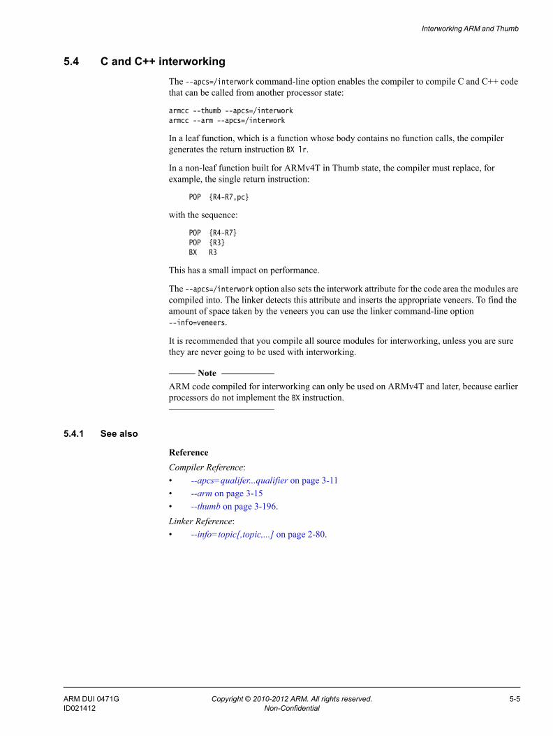
Interworking ARM and Thumb
5.4 C and C++ interworkingThe --apcs=/interwork command-line option enables the compiler to compile C and C++ code that can be called from another processor state:
armcc --thumb --apcs=/interworkarmcc --arm --apcs=/interwork
In a leaf function, which is a function whose body contains no function calls, the compiler generates the return instruction BX lr.
In a non-leaf function built for ARMv4T in Thumb state, the compiler must replace, for example, the single return instruction:
POP {R4-R7,pc}
with the sequence:
POP {R4-R7} POP {R3} BX R3
This has a small impact on performance.
The --apcs=/interwork option also sets the interwork attribute for the code area the modules are compiled into. The linker detects this attribute and inserts the appropriate veneers. To find the amount of space taken by the veneers you can use the linker command-line option --info=veneers.
It is recommended that you compile all source modules for interworking, unless you are sure they are never going to be used with interworking.
Note ARM code compiled for interworking can only be used on ARMv4T and later, because earlier processors do not implement the BX instruction.
5.4.1 See also
Reference Compiler Reference:• --apcs=qualifer...qualifier on page 3-11• --arm on page 3-15• --thumb on page 3-196.Linker Reference:• --info=topic[,topic,...] on page 2-80.
ARM DUI 0471G Copyright © 2010-2012 ARM. All rights reserved. 5-5ID021412 Non-Confidential

Interworking ARM and Thumb
5.5 Pointers to functions in Thumb stateIf you have a Thumb function, that is a function consisting of Thumb code, and that runs in Thumb state, then any pointer to that function must have the least significant bit set. This ensures that interworking works correctly.
When the linker relocates the value of a label referring to a Thumb instruction, it automatically sets the least significant bit of the relocated value. The linker cannot do this if you use absolute addresses to Thumb functions. Therefore, if you have to use an absolute address to a Thumb function in your code, you must add one to the address, see the following example.
Example 5-1 Absolute addresses to Thumb functions
typedef int (*FN)();myfunc() { FN fnptrs[] = { (FN)(0x8084 + 1), // Valid Thumb address (FN)(0x8074) // Invalid Thumb address }; FN* myfunctions = fnptrs; myfunctions[0](); // Call OK myfunctions[1](); // Call fails}
ARM DUI 0471G Copyright © 2010-2012 ARM. All rights reserved. 5-6ID021412 Non-Confidential

Interworking ARM and Thumb
5.6 Using two versions of the same functionYou can have two functions with the same name, one compiled for ARM and the other for Thumb.
The linker enables multiple definitions of a symbol to coexist in an image, only if each definition is associated with a different processor state. The linker applies the following rules when a reference is made to a symbol with ARM/Thumb synonyms:
• B, BL, or BLX instructions to a symbol from ARM state resolve to the ARM definition
• B, BL, or BLX instructions to a symbol from Thumb state resolve to the Thumb definition.
Any other reference to the symbol resolves to the first definition encountered by the linker. The linker produces a warning that specifies the chosen symbol.
Note Defining the same function name or symbol name in ARM code and in Thumb code is deprecated.
5.6.1 See also
Concepts Using the Linker:• Chapter 7 Accessing and managing symbols with armlink.
ARM DUI 0471G Copyright © 2010-2012 ARM. All rights reserved. 5-7ID021412 Non-Confidential

Interworking ARM and Thumb
5.7 Assembly language interworking exampleThis example implements a short header section (SECTION 1) followed by an ADR instruction to get the address of the label THUMBProg, and sets the least significant bit of the address. The BX instruction changes the state to Thumb state.
In SECTION2, the Thumb code adds the contents of two registers together, using an ADR instruction to get the address of the label ARMProg, leaving the least significant bit clear. The BX instruction changes the state back to ARM state.
In SECTION3 the ARM code adds together the contents of two registers and ends.
Example 5-2 Assembly language interworking
; ******** ; addreg.s ; ********
PRESERVE8 AREA AddReg,CODE,READONLY ; Name this block of code. ENTRY ; Mark first instruction to call.; SECTION1start ADR R0, ThumbProg:OR:1 ; Generate branch target address ; and set bit 0, hence arrive ; at target in Thumb state. BX R0 ; Branch exchange to ThumbProg.; SECTION2 THUMB ; Subsequent instructions are Thumb code.ThumbProg MOVS R2, #2 ; Load R2 with value 2. MOVS R3, #3 ; Load R3 with value 3. ADDS R2, R2, R3 ; R2 = R2 + R3 ADR R0, ARMProg BX R0 ; Branch exchange to ARMProg.; SECTION3 ARM ; Subsequent instructions are ARM code.ARMProg MOV R4, #4 MOV R5, #5 ADD R4, R4, R5; SECTION 4stop MOV R0, #0x18 ; angel_SWIreason_ReportException LDR R1, =0x20026 ; ADP_Stopped_ApplicationExit SVC 0x123456 ; ARM semihosting END ; Mark end of this file.
5.7.1 Building the example
Follow these steps to build and link the modules:
1. To assemble the source file for interworking, type:armasm --debug --apcs=/interwork addreg.s
2. To link the object files, type:armlink addreg.o -o addreg.axf
Alternatively, to view the size of the interworking veneers, type:armlink addreg.o -o addreg.axf --info=veneers
ARM DUI 0471G Copyright © 2010-2012 ARM. All rights reserved. 5-8ID021412 Non-Confidential
Interworking ARM and Thumb
3. Run the image using a compatible debugger with an appropriate debug target.
5.7.2 See also
Concepts • Interworking using veneers on page 5-10• C and C++ language interworking on page 5-12• C, C++, and assembly language interworking using veneers on page 5-14.
Reference Assembler Reference:• --apcs=qualifier…qualifier on page 2-5• --debug on page 2-9.Linker Reference:• --info=topic[,topic,...] on page 2-80• --output=filename on page 2-114.
ARM DUI 0471G Copyright © 2010-2012 ARM. All rights reserved. 5-9ID021412 Non-Confidential

Interworking ARM and Thumb
5.8 Interworking using veneers This example shows interworking of source code in assembly code to set registers R0 to R2 to the values 1, 2, and 3 respectively. Registers R0 and R2 are set by the ARM code. R1 is set by the Thumb code. The linker automatically adds an interworking veneer. To use veneers:• you must assemble the code with the --apcs=/interwork option• use a BX lr instruction to return, instead of MOV pc,lr.
5.8.1 Example of assembly language interworking using veneers
The following example shows assembly language interworking using veneers.
Example 5-3 Assembly language interworking using veneers
; ***** ; arm.s ; *****
PRESERVE8 AREA Arm,CODE,READONLY ; Name this block of code. IMPORT ThumbProg ENTRY ; Mark 1st instruction to call.ARMProg MOV R0,#1 ; Set R0 to show in ARM code. BL ThumbProg ; Call Thumb subroutine. MOV R2,#3 ; Set R2 to show returned to ARM. ; Terminate execution. MOV R0, #0x18 ; angel_SWIreason_ReportException LDR R1, =0x20026 ; ADP_Stopped_ApplicationExit SVC 0x123456 ; ARM semihosting (formerly SWI) END
; ******* ; thumb.s ; *******
AREA Thumb,CODE,READONLY ; Name this block of code. THUMB ; Subsequent instructions are Thumb. EXPORT ThumbProgThumbProg MOVS R1, #2 ; Set R1 to show reached Thumb code. BX lr ; Return to the ARM function. END ; Mark end of this file.
5.8.2 Building the example
Follow these steps to build and link the modules:
1. To assemble the ARM code for interworking, type:armasm --debug --apcs=/interwork arm.s
2. To assemble the Thumb code for interworking, type:armasm --thumb --debug --apcs=/interwork thumb.s
3. To link the object files, type:armlink arm.o thumb.o -o count.axf
Alternatively, to view the size of the interworking veneers, type:
ARM DUI 0471G Copyright © 2010-2012 ARM. All rights reserved. 5-10ID021412 Non-Confidential

Interworking ARM and Thumb
armlink arm.o thumb.o -o count.axf --info=veneers
4. Run the image using a compatible debugger with an appropriate debug target.
5.8.3 See also
Concepts • Assembly language interworking example on page 5-8• C and C++ language interworking on page 5-12• C, C++, and assembly language interworking using veneers on page 5-14.
Reference Assembler Reference:• --apcs=qualifier…qualifier on page 2-5• --debug on page 2-9• --thumb on page 2-24.Linker Reference:• --info=topic[,topic,...] on page 2-80• --output=filename on page 2-114.
ARM DUI 0471G Copyright © 2010-2012 ARM. All rights reserved. 5-11ID021412 Non-Confidential

Interworking ARM and Thumb
5.9 C and C++ language interworking This example shows a Thumb routine that carries out an interworking call to an ARM subroutine. The ARM subroutine makes an interworking call to printf() in the Thumb library.
Example 5-4 C and C++ language interworking
/********************* * thumbmain.c * **********************/
#include <stdio.h>
extern void arm_function(void);
int main(void) { printf("Hello from Thumb\n"); arm_function(); printf("And goodbye from Thumb\n"); return (0); }
/********************* * armsub.c * **********************/ #include <stdio.h>
void arm_function(void) { printf("Hello and Goodbye from ARM\n"); }
5.9.1 Building the example
Follow these steps to build and link the modules:
1. To compile the Thumb code for interworking, type:armcc --thumb -c --debug --apcs=/interwork thumbmain.c -o thumbmain.o
2. To compile the ARM code for interworking, type:armcc -c --debug --apcs=/interwork armsub.c -o armsub.o
3. To link the object files, type:armlink thumbmain.o armsub.o -o thumbtoarm.axf
Alternatively, to view the size of the interworking veneers, type:armlink armsub.o thumbmain.o -o thumbtoarm.axf --info=veneers
4. Run the image using a compatible debugger with an appropriate debug target.
5.9.2 See also
Concepts • Assembly language interworking example on page 5-8• Interworking using veneers on page 5-10• C, C++, and assembly language interworking using veneers on page 5-14.
ARM DUI 0471G Copyright © 2010-2012 ARM. All rights reserved. 5-12ID021412 Non-Confidential

Interworking ARM and Thumb
Reference Compiler Reference:• --apcs=qualifer...qualifier on page 3-11• -c on page 3-31• --debug, --no_debug on page 3-55• -o filename on page 3-153• --thumb on page 3-196.Linker Reference:• --info=topic[,topic,...] on page 2-80• --output=filename on page 2-114.
ARM DUI 0471G Copyright © 2010-2012 ARM. All rights reserved. 5-13ID021412 Non-Confidential
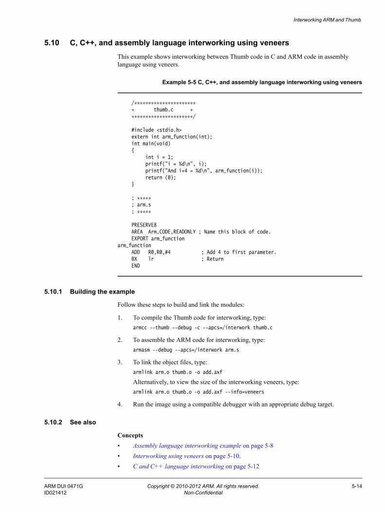
Interworking ARM and Thumb
5.10 C, C++, and assembly language interworking using veneersThis example shows interworking between Thumb code in C and ARM code in assembly language using veneers.
Example 5-5 C, C++, and assembly language interworking using veneers
/********************** * thumb.c * **********************/
#include <stdio.h> extern int arm_function(int); int main(void) { int i = 1; printf("i = %d\n", i); printf("And i+4 = %d\n", arm_function(i)); return (0); }
; ***** ; arm.s ; *****
PRESERVE8 AREA Arm,CODE,READONLY ; Name this block of code. EXPORT arm_functionarm_function ADD R0,R0,#4 ; Add 4 to first parameter. BX lr ; Return END
5.10.1 Building the example
Follow these steps to build and link the modules:
1. To compile the Thumb code for interworking, type:armcc --thumb --debug -c --apcs=/interwork thumb.c
2. To assemble the ARM code for interworking, type:armasm --debug --apcs=/interwork arm.s
3. To link the object files, type:armlink arm.o thumb.o -o add.axf
Alternatively, to view the size of the interworking veneers, type:armlink arm.o thumb.o -o add.axf --info=veneers
4. Run the image using a compatible debugger with an appropriate debug target.
5.10.2 See also
Concepts • Assembly language interworking example on page 5-8• Interworking using veneers on page 5-10.• C and C++ language interworking on page 5-12
ARM DUI 0471G Copyright © 2010-2012 ARM. All rights reserved. 5-14ID021412 Non-Confidential

Interworking ARM and Thumb
Reference Compiler Reference:• --apcs=qualifer...qualifier on page 3-11• -c on page 3-31• --debug, --no_debug on page 3-55• -o filename on page 3-153• --thumb on page 3-196.Assembler Reference:• --apcs=qualifier…qualifier on page 2-5• --debug on page 2-9.Linker Reference:• --info=topic[,topic,...] on page 2-80• --output=filename on page 2-114.
ARM DUI 0471G Copyright © 2010-2012 ARM. All rights reserved. 5-15ID021412 Non-Confidential

Chapter 6 Handling Processor Exceptions
The following topics describe how to handle the different types of exception supported by the ARM architecture:• About processor exceptions on page 6-3• Exception handling process on page 6-4• Types of exception in ARMv6 and earlier, ARMv7-A and ARMv7-R profiles on page 6-5• Vector table for ARMv6 and earlier, ARMv7-A and ARMv7-R profiles on page 6-6• Processor modes and registers in ARMv6 and earlier, ARMv7-A and ARMv7-R profiles on
page 6-7• Use of System mode for exception handling on page 6-8• The processor response to an exception on page 6-9• Return from an exception handler on page 6-10• Reset handlers on page 6-11• Data Abort handler on page 6-12• Interrupt handlers and levels of external interrupt on page 6-13• Reentrant interrupt handlers on page 6-14• Example interrupt handlers in assembly language on page 6-17• Single-channel DMA transfer on page 6-18• Dual-channel DMA transfer on page 6-19• Interrupt prioritization on page 6-20• Context switch on page 6-22• SVC handlers on page 6-23• Determining the SVC to be called on page 6-25• SVC handlers in assembly language on page 6-26• SVC handlers in C and assembly language on page 6-27
ARM DUI 0471G Copyright © 2010-2012 ARM. All rights reserved. 6-1ID021412 Non-Confidential

Handling Processor Exceptions
• Using SVCs in Supervisor mode on page 6-29• Calling SVCs from an application on page 6-30• Calling SVCs dynamically from an application on page 6-32• Prefetch Abort handler on page 6-34• Undefined instruction handlers on page 6-35• ARMv6-M and ARMv7-M profiles on page 6-36• Main and Process Stacks on page 6-37• Types of exceptions in the microcontroller profiles on page 6-38• Vector table for ARMv6-M and ARMv7-M profiles on page 6-39• Vector Table Offset Register (ARMv7-M only) on page 6-40• Writing the exception table for ARMv6-M and ARMv7-M profiles on page 6-41• The Nested Vectored Interrupt Controller on page 6-42• Handling an exception on page 6-43• Configuring the System Control Space registers on page 6-45• Configuring individual IRQs on page 6-47• Supervisor calls on page 6-48• System timer on page 6-50• Configuring SysTick on page 6-51.
ARM DUI 0471G Copyright © 2010-2012 ARM. All rights reserved. 6-2ID021412 Non-Confidential
Handling Processor Exceptions
6.1 About processor exceptionsDuring the normal flow of execution through a program, the Program Counter (PC) increases sequentially through the address space, with branches to nearby labels or branch with links to subroutines.
Processor exceptions occur when this normal flow of execution is diverted, to enable the processor to handle events generated by internal or external sources. Examples of such events are:• externally generated interrupts• an attempt by the processor to execute an undefined instruction• accessing privileged operating system functions.
6.1.1 See also
Concepts • Exception handling process on page 6-4.
ARM DUI 0471G Copyright © 2010-2012 ARM. All rights reserved. 6-3ID021412 Non-Confidential

Handling Processor Exceptions
6.2 Exception handling processThe following figure shows the exception handling process.
Figure 6-1 Handling an exception
When an exception occurs, control passes through an area of memory called the vector table. This is a reserved area usually at the bottom of the memory map. Within the table one word is allocated to each of the various exception types. This word contains either a form of a branch instruction or, in the case of ARMv6-M and ARMv7-M, an address to the relevant exception handler.
You can write the exception handlers in either ARM or Thumb code if the processor supports the respective instruction set. For the ARMv7-M and ARMv6-M profiles, the processor enters the exception handler that is specified in the vector table. For all other ARM processors, you must branch from the top-level handler to the code that handles the exception. Use a Branch and exchange (BX) if state change is required. When handling exceptions, the current processor mode, state, and registers must be preserved so that the program can resume when the appropriate exception handling routine completes.
The exception handling model used by ARMv7-A, ARMv7-R, ARMv6 and earlier architectures is different from the model used by the microcontroller profiles ARMv6-M and ARMv7-M.
6.2.1 See also
Concepts • Types of exception in ARMv6 and earlier, ARMv7-A and ARMv7-R profiles on page 6-5• ARMv6-M and ARMv7-M profiles on page 6-36.
Reference • Chapter 5 Interworking ARM and Thumb.
Applicationcode
Exception occurs
Vectortable
Handle
exception
Save CPU andregister state
Restore CPUandregister state
the
ARM DUI 0471G Copyright © 2010-2012 ARM. All rights reserved. 6-4ID021412 Non-Confidential

Handling Processor Exceptions
6.3 Types of exception in ARMv6 and earlier, ARMv7-A and ARMv7-R profilesThe following table shows the different types of exception recognized by ARMv6 and earlier, the ARMv7-A and ARMv7-R profiles. When exceptions occur simultaneously, they are handled in a fixed order of priority. Each exception is handled in turn before returning to the original application. It is not possible for all exceptions to occur concurrently. For example, the undefined instruction (Undef) and supervisor call (SVC) exceptions are mutually exclusive because they are both triggered by executing an instruction.
On entry to an exception:• interrupt requests (IRQs) are disabled for all exceptions• fast interrupt requests (FIQs) are disabled for FIQ and Reset exceptions.
Because the Data Abort exception has a higher priority than the FIQ exception, the Data Abort is actually registered before the FIQ is handled. The Data Abort handler is entered, but control is then passed immediately to the FIQ handler because the FIQ remains enabled when handling a Data Abort. When the FIQ has been handled, control returns to the Data Abort Handler. This means that data transfer errors do not escape detection as they would if the FIQ was handled first.
6.3.1 See also
Reference • ARMv6-M and ARMv7-M profiles on page 6-36.
Table 6-1 Exception types in priority order
Priority (1=high, 6=low)
Exception type Exception mode Description
1 Reset Supervisor Occurs when the processor reset pin is asserted. This exception is only expected to occur for signaling power-up, or for resetting if the processor is already powered up. A soft reset can be done by branching to the reset vector.
2 Data Abort Abort Occurs when a data transfer instruction attempts to load or store data at an illegal addressa.
3 FIQ FIQ Occurs when the processor external fast interrupt request pin is asserted (LOW) and the F bit in the CPSR is clear.
4 IRQ IRQ Occurs when the processor external interrupt request pin is asserted (LOW) and the I bit in the CPSR is clear.
5 Prefetch Abort Abort Occurs when the processor attempts to execute an instruction that was not fetched, because the address was illegala.
6 SVC Supervisor This is a user-defined synchronous interrupt instruction. It enables a program running in User mode, for example, to request privileged operations that run in Supervisor mode, such as an RTOS function.
6 Undefined Instruction Undef Occurs if neither the processor, nor any attached coprocessor, recognizes the currently executing instruction.
a. An illegal virtual address is one that does not currently correspond to an address in physical memory, or one that the memory management subsystem has determined is inaccessible to the processor in its current mode.
ARM DUI 0471G Copyright © 2010-2012 ARM. All rights reserved. 6-5ID021412 Non-Confidential

Handling Processor Exceptions
6.4 Vector table for ARMv6 and earlier, ARMv7-A and ARMv7-R profilesThe vector table for ARMv6 and earlier, ARMv7-A and ARMv7-R profiles consists of a branch or load PC instruction to the relevant handler. If required, you can include the FIQ handler at the end of the vector table to ensure it is handled as efficiently as possible, see the following example. Using a literal pool means that addresses can easily be modified later if necessary.
Example 6-1 Typical vector table using a literal pool
AREA vectors, CODE, READONLYENTRY
Vector_TableLDR pc, Reset_AddrLDR pc, Undefined_AddrLDR pc, SVC_AddrLDR pc, Prefetch_AddrLDR pc, Abort_AddrNOP ;Reserved vectorLDR pc, IRQ_Addr
FIQ_Handler; FIQ handler code - max 4kB in size
Reset_Addr DCD Reset_HandlerUndefined_Addr DCD Undefined_HandlerSVC_Addr DCD SVC_HandlerPrefetch_Addr DCD Prefetch_HandlerAbort_Addr DCD Abort_HandlerIRQ_Addr DCD IRQ_Handler
...END
This example assumes that you have ROM at location 0x0 on reset. Alternatively, you can use the scatter-loading mechanism to define the load and execution address of the vector table. In that case, the C library copies the vector table for you.
Note The vector table for ARMv6 and earlier architectures supports ARM instructions only. ARMv6T2 and later architectures support both 32-bit Thumb and ARM instructions in the vector table. This does not apply to the ARMv6-M and ARMv7-M profiles.
6.4.1 See also
Concepts Using the Linker:• Chapter 8 Using scatter files.
ARM DUI 0471G Copyright © 2010-2012 ARM. All rights reserved. 6-6ID021412 Non-Confidential

Handling Processor Exceptions
6.5 Processor modes and registers in ARMv6 and earlier, ARMv7-A and ARMv7-R profiles
The ARM architecture defines an unprivileged User mode containing 15 general purpose registers, a PC, and a CPSR. In addition there are other privileged modes, each containing a SPSR and a number of banked out registers.
Typically, an application runs in User mode, but handling exceptions requires a privileged mode. An exception changes the processor mode, and this in turn means that each exception handler has access to a certain subset of the banked out registers: • its own Stack Pointer (SP)• its own LR• its own SPSR• five additional general purpose registers (FIQ only).
Each exception handler must ensure that other registers are restored to their original contents on exit. You can do this by saving the contents of any registers that the handler requires onto its stack and restore them before returning.
6.5.1 See also
Reference • Reentrant interrupt handlers on page 6-14• Example interrupt handlers in assembly language on page 6-17.
ARM DUI 0471G Copyright © 2010-2012 ARM. All rights reserved. 6-7ID021412 Non-Confidential

Handling Processor Exceptions
6.6 Use of System mode for exception handlingCorruption of the link register can be a problem when handling multiple exceptions of the same type.
ARMv4 and later architectures include a privileged mode called System mode, to overcome this problem. System mode shares the same registers as User mode, it can run tasks that require privileged access, and exceptions no longer overwrite the link register.
Note System mode cannot be entered by an exception. The exception handlers modify the CPSR to enter System mode.
6.6.1 See also
Concepts • Processor modes and registers in ARMv6 and earlier, ARMv7-A and ARMv7-R profiles on
page 6-7.
ARM DUI 0471G Copyright © 2010-2012 ARM. All rights reserved. 6-8ID021412 Non-Confidential

Handling Processor Exceptions
6.7 The processor response to an exceptionThis describes the processor response to an exception. You must ensure that the exception handler saves the system state when an exception occurs and restores it on return.
Processors that support Thumb state use the same basic exception handling mechanism as processors that do not support Thumb state. An exception causes the next instruction to be fetched from the appropriate vector table entry.
When an exception is generated, the processor performs the following actions:
1. Copies the CPSR into the appropriate SPSR. This saves the current mode, interrupt mask, and condition flags.
2. Switches state automatically if the current state does not match the instruction set used in the exception vector table.
3. Changes the appropriate CPSR mode bits to:• Change to the appropriate mode, and map in the appropriate banked out registers
for that mode.• Disable interrupts. IRQs are disabled when any exception occurs. FIQs are disabled
when an FIQ occurs and on reset.
4. Sets the appropriate LR to the return address.
5. Sets the PC to the vector address for the exception.
ARM DUI 0471G Copyright © 2010-2012 ARM. All rights reserved. 6-9ID021412 Non-Confidential

Handling Processor Exceptions
6.8 Return from an exception handlerThis describes the processor response to an exception, and how to return to the main program after the exception has been handled. You must ensure that the exception handler saves the system state when an exception occurs and restores it on return.
The method used to return from an exception depends on whether the exception handler uses stack operations or not. In both cases, to return execution to the place where the exception occurred an exception handler must: • restore the CPSR from the appropriate SPSR• restore the PC using the return address from the appropriate LR.
For a simple return that does not require the destination mode registers to be restored from the stack, the exception handler carries out these operations by performing a data processing instruction with:• the S flag set• the PC as the destination register.
The return instruction required depends on the type of exception.
Note You do not have to return from the reset handler because the reset handler executes your main code directly.
If the exception handler entry code uses the stack to store registers that must be preserved while it handles the exception, it can return using a load multiple instruction with the ^ qualifier. For example, an exception handler can return in one instruction using:
LDMFD sp!,{R0-R12,pc}^
To do this, the exception handler must save the following onto the stack:
• all the work registers in use when the handler is invoked
• the link register, modified to produce the same effect as the data processing instructions.
The ^ qualifier specifies that the CPSR is restored from the SPSR. It must be used only from a privileged mode.
Note You cannot use any 16-bit Thumb instruction to return from exceptions because these are unable to restore the CPSR.
6.8.1 See also
Reference Using the Assembler:• Stack implementation using LDM and STM on page 5-22.
ARM DUI 0471G Copyright © 2010-2012 ARM. All rights reserved. 6-10ID021412 Non-Confidential
Handling Processor Exceptions
6.9 Reset handlersThe operations carried out by the Reset handler depend on the system that the software is being developed for.
For example, it might: • set up exception vectors• initialize stacks and registers• initialize the memory system, if using an MMU• initialize any critical I/O devices• enable interrupts• change processor mode and/or state• initialize variables required by C and call the main application.
6.9.1 See also
Reference • Vector table for ARMv6 and earlier, ARMv7-A and ARMv7-R profiles on page 6-6• Chapter 3 Embedded Software Development.
ARM DUI 0471G Copyright © 2010-2012 ARM. All rights reserved. 6-11ID021412 Non-Confidential

Handling Processor Exceptions
6.10 Data Abort handlerIf there is no MMU, the Data Abort handler must report the error and quit. If there is an MMU, the handler must deal with the virtual memory fault.
The instruction that caused the abort is at lr_ABT-8 because lr_ABT points two instructions beyond the instruction that caused the abort.
The following types of instruction can cause this abort:
Single Register Load or Store The response depends on the processor type: • If the abort takes place on an ARM7™, including the ARM7TDMI, the base
register, specified in the instruction, has been updated and the change must be undone.
• If the abort takes place on an ARM9™ or later processor, the address is restored by the processor to the value it had before the instruction started. No code is required to undo the change.
Swap (SWP) There is no address register update involved with this instruction.
Load Multiple or Store Multiple The response depends on the processor type: • If the abort takes place on an ARM7 processor, and writeback is enabled,
the base register is updated as if the whole transfer had taken place. In the case of an LDM with the base register in the register list, the processor replaces the overwritten value with the modified base value so that recovery is possible. The original base address can then be recalculated using the number of registers involved.
• If the abort takes place on an ARM9 or later processor and writeback is enabled, the base register is restored to the value it had before the instruction started.
In each of the three cases the MMU can load the required virtual memory into physical memory. The MMU Fault Address Register (FAR) contains the address that caused the abort. When this is done, the handler can return and try to execute the instruction again.
ARM DUI 0471G Copyright © 2010-2012 ARM. All rights reserved. 6-12ID021412 Non-Confidential
Handling Processor Exceptions
6.11 Interrupt handlers and levels of external interruptThe ARM processor has two levels of external interrupt, FIQ and IRQ, both of which are level-sensitive active LOW signals into the processor. For an interrupt to be taken, the appropriate disable bit in the CPSR must be clear.
FIQs have higher priority than IRQs in the following ways:
• FIQs are handled first when multiple interrupts occur.
• Handling an FIQ causes IRQs and subsequent FIQs to be disabled, preventing them from being handled until after the FIQ handler enables them. This is usually done by restoring the CPSR from the SPSR at the end of the handler.
The FIQ vector is the last entry in the vector table so that the FIQ handler can be placed directly at the vector location and run sequentially from that address. This removes the requirement for a branch and its associated delay, and also means that if the system has a cache, the vector table and FIQ handler might all be locked down in one block within it. This is important because FIQs are designed to handle interrupts as quickly as possible. The five extra FIQ mode banked registers enable status to be held between calls to the handler, again increasing execution speed.
Note An interrupt handler must contain code to clear the source of the interrupt.
6.11.1 See also
Concepts • Reentrant interrupt handlers on page 6-14.
ARM DUI 0471G Copyright © 2010-2012 ARM. All rights reserved. 6-13ID021412 Non-Confidential

Handling Processor Exceptions
6.12 Reentrant interrupt handlersIf an interrupt handler enables interrupts before calling a subroutine and another interrupt occurs, the return address of the subroutine stored in the IRQ mode LR is corrupted when the second IRQ is taken. This is because the processor automatically saves the return address into the IRQ mode LR for the new interrupt overwriting the return address for the subroutine. This results in an infinite loop when the subroutine in the original interrupt tries to return.
A reentrant interrupt handler must save the IRQ state, switch processor modes, and save the state for the new processor mode before branching to a nested subroutine or C function. It must also ensure that the stack is eight-byte aligned for the new processor mode before calling AAPCS-compliant compiled C code that might use LDRD or STRD instructions or eight-byte aligned stack-allocated data.
Using the __irq keyword in C does not cause the SPSR to be saved and restored, as required by reentrant interrupt handlers, so you must write your top level interrupt handler in assembly language.
In ARMv4 or later you can switch to System mode if you require privileged access.
Note This method works for both IRQ and FIQ interrupts. However, because FIQ interrupts are meant to be handled as quickly as possible there is normally only one interrupt source, so it might not be necessary to provide for reentrancy.
The steps required to enable interrupts safely in an IRQ handler are:
1. Construct the return address and save it on the IRQ stack.
2. Save the work registers, non callee-saved registers and IRQ mode SPSR.
3. Clear the source of the interrupt.
4. Switch to System mode, keeping IRQs disabled.
5. Check that the stack is eight-byte aligned and adjust if necessary.
6. Save the User mode LR and the adjustment, 0 or 4 for Architectures v4 or v5TE, used on the User mode SP.
7. Enable interrupts and call the C interrupt handler function.
8. When the C interrupt handler returns, disable interrupts.
9. Restore the User mode LR and the stack adjustment value.
10. Readjust the stack if necessary.
11. Switch to IRQ mode.
12. Restore other registers and IRQ mode SPSR.
13. Return from the IRQ.
The following examples show how this works for System mode.
ARM DUI 0471G Copyright © 2010-2012 ARM. All rights reserved. 6-14ID021412 Non-Confidential
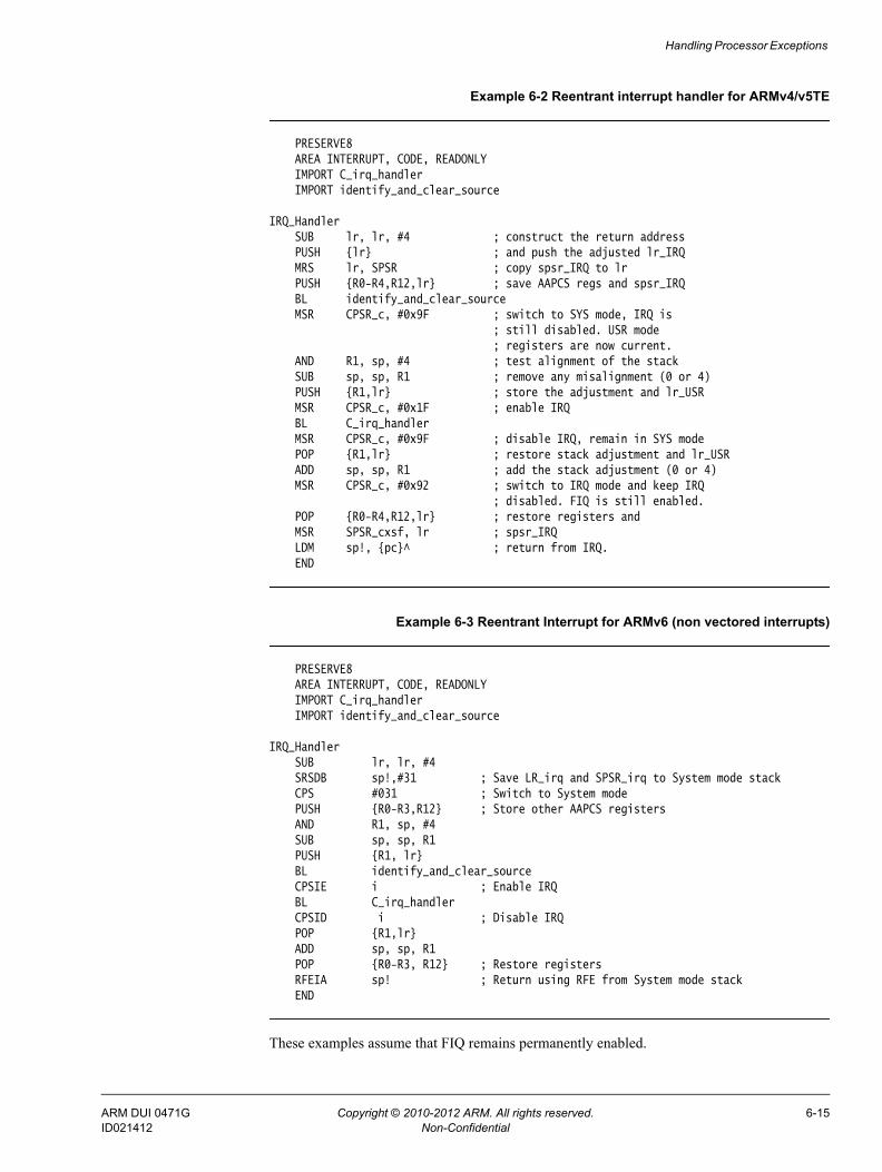
Handling Processor Exceptions
Example 6-2 Reentrant interrupt handler for ARMv4/v5TE
PRESERVE8AREA INTERRUPT, CODE, READONLYIMPORT C_irq_handlerIMPORT identify_and_clear_source
IRQ_Handler SUB lr, lr, #4 ; construct the return address
PUSH {lr} ; and push the adjusted lr_IRQ MRS lr, SPSR ; copy spsr_IRQ to lr
PUSH {R0-R4,R12,lr} ; save AAPCS regs and spsr_IRQBL identify_and_clear_sourceMSR CPSR_c, #0x9F ; switch to SYS mode, IRQ is
; still disabled. USR mode ; registers are now current. AND R1, sp, #4 ; test alignment of the stack SUB sp, sp, R1 ; remove any misalignment (0 or 4)
PUSH {R1,lr} ; store the adjustment and lr_USR MSR CPSR_c, #0x1F ; enable IRQ BL C_irq_handler MSR CPSR_c, #0x9F ; disable IRQ, remain in SYS mode
POP {R1,lr} ; restore stack adjustment and lr_USR ADD sp, sp, R1 ; add the stack adjustment (0 or 4) MSR CPSR_c, #0x92 ; switch to IRQ mode and keep IRQ ; disabled. FIQ is still enabled.
POP {R0-R4,R12,lr} ; restore registers and MSR SPSR_cxsf, lr ; spsr_IRQ LDM sp!, {pc}^ ; return from IRQ. END
Example 6-3 Reentrant Interrupt for ARMv6 (non vectored interrupts)
PRESERVE8AREA INTERRUPT, CODE, READONLYIMPORT C_irq_handlerIMPORT identify_and_clear_source
IRQ_HandlerSUB lr, lr, #4SRSDB sp!,#31 ; Save LR_irq and SPSR_irq to System mode stackCPS #031 ; Switch to System modePUSH {R0-R3,R12} ; Store other AAPCS registersAND R1, sp, #4SUB sp, sp, R1PUSH {R1, lr}BL identify_and_clear_sourceCPSIE i ; Enable IRQBL C_irq_handlerCPSID i ; Disable IRQPOP {R1,lr}ADD sp, sp, R1POP {R0-R3, R12} ; Restore registersRFEIA sp! ; Return using RFE from System mode stackEND
These examples assume that FIQ remains permanently enabled.
ARM DUI 0471G Copyright © 2010-2012 ARM. All rights reserved. 6-15ID021412 Non-Confidential

Handling Processor Exceptions
6.12.1 See also
Reference • Use of System mode for exception handling on page 6-8.
Other information • ABI for the ARM Architecture Advisory Note 1- SP must be 8-byte aligned on entry to
AAPCS-conforming functions, http://infocenter/help/topic/com.arm.doc.ihi0046-/index.html
• Application Note 30: Software Prioritization of Interrupts, http://infocenter/help/topic/com.arm.doc.dai0030-/index.html.
ARM DUI 0471G Copyright © 2010-2012 ARM. All rights reserved. 6-16ID021412 Non-Confidential
Handling Processor Exceptions
6.13 Example interrupt handlers in assembly languageInterrupt handlers are often written in assembly language to ensure that they execute quickly. The following provide examples:• Single-channel DMA transfer on page 6-18• Dual-channel DMA transfer on page 6-19• Interrupt prioritization on page 6-20• Context switch on page 6-22.
ARM DUI 0471G Copyright © 2010-2012 ARM. All rights reserved. 6-17ID021412 Non-Confidential

Handling Processor Exceptions
6.14 Single-channel DMA transferThe following examples show an interrupt handler that performs interrupt driven I/O to memory transfers, soft DMA. The code is an FIQ handler. It uses the banked FIQ registers to maintain state between interrupts. This code is best situated at location 0x1C.
In the example code:
R8 Points to the base address of the I/O device that data is read from.
IOData Is the offset from the base address to the 32-bit data register that is read. Reading this register clears the interrupt.
R9 Points to the memory location to where that data is being transferred.
R10 Points to the last address to transfer to.
The entire sequence for handling a normal transfer is four instructions. Code situated after the conditional return is used to signal that the transfer is complete.
Example 6-4 FIQ handler
LDR R11, [R8, #IOData] ; Load port data from the IO device. STR R11, [R9], #4 ; Store it to memory: update the pointer. CMP R9, R10 ; Reached the end ? SUBLSS pc, lr, #4 ; No, so return. ; Insert transfer complete ; code here.
Byte transfers can be made by replacing the load instructions with load byte instructions. Transfers from memory to an I/O device are made by swapping the addressing modes between the load instruction and the store instruction.
ARM DUI 0471G Copyright © 2010-2012 ARM. All rights reserved. 6-18ID021412 Non-Confidential

Handling Processor Exceptions
6.15 Dual-channel DMA transferThe FIQ handler example here is similar to the FIQ handler on page 6-18 example, except that there are two channels being handled. The code is an FIQ handler. It uses the banked FIQ registers to maintain state between interrupts. It is best situated at location 0x1C.
In the example code:
R8 Points to the base address of the I/O device from which data is read.
IOStat Is the offset from the base address to a register indicating which of two ports caused the interrupt.
IOPort1Active Is a bit mask indicating if the first port caused the interrupt. Otherwise it is assumed that the second port caused the interrupt.
IOPort1, IOPort2 Are offsets to the two data registers to be read. Reading a data register clears the interrupt for the corresponding port.
R9 Points to the memory location to which data from the first port is being transferred.
R10 Points to the memory location to which data from the second port is being transferred.
R11, R12 Point to the last address to transfer to. This is R11 for the first port, R12 for the second.
The entire sequence to handle a normal transfer takes nine instructions. Code situated after the conditional return is used to signal that the transfer is complete.
Example 6-5 FIQ handler
LDR sp, [R8, #IOStat] ; Load status register to find which port; caused the interrupt.
TST sp, #IOPort1Active LDREQ sp, [R8, #IOPort1] ; Load port 1 data. LDRNE sp, [R8, #IOPort2] ; Load port 2 data. STREQ sp, [R9], #4 ; Store to buffer 1. STRNE sp, [R10], #4 ; Store to buffer 2. CMP R9, R11 ; Reached the end? CMPLE R10, R12 ; On either channel?
SUBSNE pc, lr, #4 ; Return ; Insert transfer complete code here.
Byte transfers can be made by replacing the load instructions with load byte instructions. Transfers from memory to an I/O device are made by swapping the addressing modes between the conditional load instructions and the conditional store instructions.
ARM DUI 0471G Copyright © 2010-2012 ARM. All rights reserved. 6-19ID021412 Non-Confidential
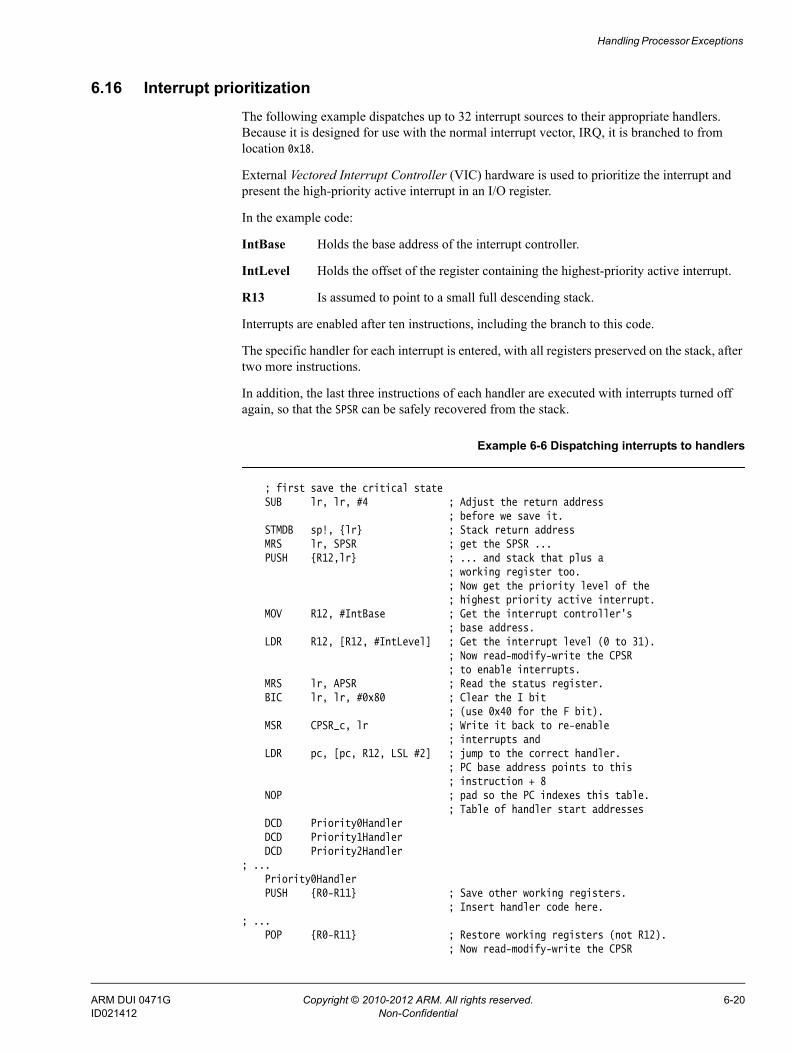
Handling Processor Exceptions
6.16 Interrupt prioritizationThe following example dispatches up to 32 interrupt sources to their appropriate handlers. Because it is designed for use with the normal interrupt vector, IRQ, it is branched to from location 0x18.
External Vectored Interrupt Controller (VIC) hardware is used to prioritize the interrupt and present the high-priority active interrupt in an I/O register.
In the example code:
IntBase Holds the base address of the interrupt controller.
IntLevel Holds the offset of the register containing the highest-priority active interrupt.
R13 Is assumed to point to a small full descending stack.
Interrupts are enabled after ten instructions, including the branch to this code.
The specific handler for each interrupt is entered, with all registers preserved on the stack, after two more instructions.
In addition, the last three instructions of each handler are executed with interrupts turned off again, so that the SPSR can be safely recovered from the stack.
Example 6-6 Dispatching interrupts to handlers
; first save the critical state SUB lr, lr, #4 ; Adjust the return address ; before we save it. STMDB sp!, {lr} ; Stack return address MRS lr, SPSR ; get the SPSR ...
PUSH {R12,lr} ; ... and stack that plus a ; working register too. ; Now get the priority level of the ; highest priority active interrupt. MOV R12, #IntBase ; Get the interrupt controller's ; base address. LDR R12, [R12, #IntLevel] ; Get the interrupt level (0 to 31). ; Now read-modify-write the CPSR
; to enable interrupts. MRS lr, APSR ; Read the status register. BIC lr, lr, #0x80 ; Clear the I bit ; (use 0x40 for the F bit). MSR CPSR_c, lr ; Write it back to re-enable ; interrupts and LDR pc, [pc, R12, LSL #2] ; jump to the correct handler. ; PC base address points to this ; instruction + 8 NOP ; pad so the PC indexes this table. ; Table of handler start addresses DCD Priority0Handler DCD Priority1Handler DCD Priority2Handler; ... Priority0Handler
PUSH {R0-R11} ; Save other working registers. ; Insert handler code here.; ...
POP {R0-R11} ; Restore working registers (not R12). ; Now read-modify-write the CPSR
ARM DUI 0471G Copyright © 2010-2012 ARM. All rights reserved. 6-20ID021412 Non-Confidential

Handling Processor Exceptions
; to disable interrupts. MRS R12, APSR ; Read the status register. ORR R12, R12, #0x80 ; Set the I bit ; (use 0x40 for the F bit). MSR CPSR_c, R12 ; Write it back to disable interrupts. ; Now that interrupt disabled, can safely
; restore SPSR then return.POP {r12,lr} ; Restore R12 and get SPSR.
MSR SPSR_cxsf, lr ; Restore status register from R14. LDM sp!, {pc}^ ; Return from handler.Priority1Handler; ...
ARM DUI 0471G Copyright © 2010-2012 ARM. All rights reserved. 6-21ID021412 Non-Confidential

Handling Processor Exceptions
6.17 Context switchThe following example performs a context switch on the User mode process. The code is based around a list of pointers to Process Control Blocks (PCBs) of processes that are ready to run.
This figure shows the layout of the PCBs that the example expects.
Figure 6-2 PCB layout
The pointer to the PCB of the next process to run is pointed to by R12, and the end of the list has a zero pointer. Register R13 is a pointer to the PCB, and is preserved between time slices, so that on entry it points to the PCB of the currently running process.
Example 6-7 Context switch on the User mode process
STM sp,{R0-lr}^ ; Dump user registers above R13. MRS R0, SPSR ; Pick up the user status STMDB sp, {R0, lr} ; and dump with return address below. LDR sp, [R12], #4 ; Load next process info pointer. CMP sp, #0 ; If it is zero, it is invalid
LDMDBNE sp, {R0, lr} ; Pick up status and return address. MSRNE SPSR_cxsf, R0 ; Restore the status. LDMNE sp, {R0 - lr}^ ; Get the rest of the registers NOP SUBSNE pc, lr, #4 ; and return and restore CPSR. ; Insert "no next process code" here.
r8r7r6r5r4r3r2r1r0lr
spsr
r9r10r11r12r13r14
PCB pointer
User mode registers
ARM DUI 0471G Copyright © 2010-2012 ARM. All rights reserved. 6-22ID021412 Non-Confidential

Handling Processor Exceptions
6.18 SVC handlersAn exception handler might have to determine whether the processor was in ARM or Thumb state when the exception occurred.
SVC handlers, especially, might have to read the processor state. This is done by examining the SPSR T-bit. This bit is set for Thumb state and clear for ARM state.
Both ARM and Thumb instruction sets have the SVC instruction. When calling SVCs from Thumb state, you must consider the following:
• The instruction address is at lr–2, rather than lr–4.
• The instruction itself is 16-bit, and so requires a halfword load, see Figure 6-3.
• The SVC number is held in 8 bits instead of the 24 bits in ARM state.
Figure 6-3 Thumb SVC instruction
The following example shows ARM code that handles an SVC exception. The range of SVC numbers accessible from Thumb state can be increased by calling SVCs dynamically.
Example 6-8 SVC handler
PRESERVE8AREA SVC_Area, CODE, READONLYEXPORT SVC_Handler IMPORT C_SVC_Handler
T_bit EQU 0x20 ; Thumb bit (5) of CPSR/SPSR.SVC_Handler
STMFD sp!, {r0-r3, r12, lr} ; Store registersMOV r1, sp ; Set pointer to parametersMRS r0, spsr ; Get spsrSTMFD sp!, {r0, r3} ; Store spsr onto stack and another
; register to maintain 8-byte-aligned stackTST r0, #T_bit ; Occurred in Thumb state?LDRNEH r0, [lr,#-2] ; Yes: Load halfword and...BICNE r0, r0, #0xFF00 ; ...extract comment fieldLDREQ r0, [lr,#-4] ; No: Load word and...BICEQ r0, r0, #0xFF000000 ; ...extract comment field
; r0 now contains SVC number; r1 now contains pointer to stacked registers
BL C_SVC_Handler ; Call main part of handlerLDMFD sp!, {r0, r3} ; Get spsr from stackMSR SPSR_cxsf, r0 ; Restore spsrLDMFD sp!, {r0-r3, r12, pc}^ ; Restore registers and returnEND
6.18.1 See also
Concepts • Determining the SVC to be called on page 6-25
15 14 13121110 9 8 7 0
comment field
8_bit_immediate1 1 11 1 110
ARM DUI 0471G Copyright © 2010-2012 ARM. All rights reserved. 6-23ID021412 Non-Confidential

Handling Processor Exceptions
• SVC handlers in assembly language on page 6-26• SVC handlers in C and assembly language on page 6-27• Using SVCs in Supervisor mode on page 6-29• Calling SVCs from an application on page 6-30• Calling SVCs dynamically from an application on page 6-32.
ARM DUI 0471G Copyright © 2010-2012 ARM. All rights reserved. 6-24ID021412 Non-Confidential

Handling Processor Exceptions
6.19 Determining the SVC to be calledWhen the SVC handler is entered, it must establish which SVC is being called. This information can be stored in bits 0-23 of the instruction itself, as shown in Figure 6-4, or passed in an integer register, usually one of R0-R3.
Figure 6-4 ARM SVC instruction
The top-level SVC handler can load the SVC instruction relative to the LR. Do this in assembly language, C/C++ inline, or embedded assembler.
The handler must first load the SVC instruction that caused the exception into a register. At this point, the SVC LR holds the address of the instruction that follows the SVC instruction, so the SVC is loaded into the register, in this case R0, using:
LDR R0, [lr,#-4]
The handler can then examine the comment field bits, to determine the required operation. The SVC number is extracted by clearing the top eight bits of the opcode:
BIC R0, R0, #0xFF000000
The following example shows how you can put these instructions together to form a top-level SVC handler. For an example of a handler that deals with SVC instructions in both ARM state and Thumb state, see the SVC handler on page 6-23 example.
Example 6-9 Top-level SVC handler
PRESERVE8 AREA TopLevelSVC, CODE, READONLY ; Name this block of code. EXPORT SVC_HandlerSVC_Handler
PUSH {R0-R12,lr} ; Store registers. LDR R0,[lr,#-4] ; Calculate address of SVC instruction
; and load it into R0. BIC R0,R0,#0xFF000000 ; Mask off top 8 bits of instruction
; to give SVC number. ; ; Use value in R0 to determine which SVC routine to execute. ; LDM sp!, {R0-R12,pc}^ ; Restore registers and return. END
31 28 27 26 25 24 23 0cond 24_bit_immediate1 1 1 1
comment field
ARM DUI 0471G Copyright © 2010-2012 ARM. All rights reserved. 6-25ID021412 Non-Confidential
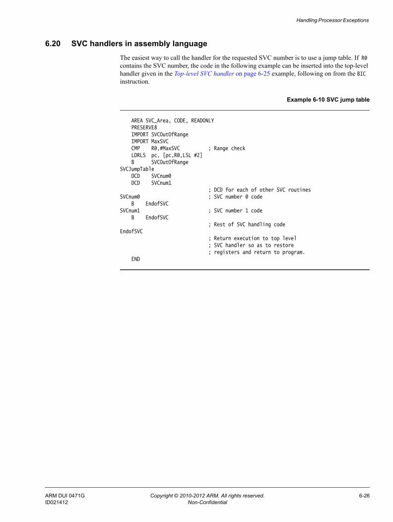
Handling Processor Exceptions
6.20 SVC handlers in assembly languageThe easiest way to call the handler for the requested SVC number is to use a jump table. If R0 contains the SVC number, the code in the following example can be inserted into the top-level handler given in the Top-level SVC handler on page 6-25 example, following on from the BIC instruction.
Example 6-10 SVC jump table
AREA SVC_Area, CODE, READONLYPRESERVE8IMPORT SVCOutOfRangeIMPORT MaxSVC
CMP R0,#MaxSVC ; Range check LDRLS pc, [pc,R0,LSL #2] B SVCOutOfRangeSVCJumpTable DCD SVCnum0 DCD SVCnum1 ; DCD for each of other SVC routinesSVCnum0 ; SVC number 0 code B EndofSVCSVCnum1 ; SVC number 1 code B EndofSVC ; Rest of SVC handling codeEndofSVC ; Return execution to top level ; SVC handler so as to restore ; registers and return to program.
END
ARM DUI 0471G Copyright © 2010-2012 ARM. All rights reserved. 6-26ID021412 Non-Confidential

Handling Processor Exceptions
6.21 SVC handlers in C and assembly languageAlthough the top-level handler must always be written in ARM assembly language, the routines that handle each SVC can be written in either assembly language or in C.
The top-level handler uses a BL instruction to jump to the appropriate C function. Because the SVC number is loaded into R0 by the assembly routine, this is passed to the C function as the first parameter. The function can use this value in, for example, a switch() statement, see the following example.
To call this C function you can add the following line to the SVC_Handler routine in the Top-level SVC handler on page 6-25 example:
BL C_SVC_Handler ; Call C routine to handle the SVC
Example 6-11 SVC handler in C function
void C_SVC_handler (unsigned number){ switch (number) { case 0 : /* SVC number 0 code */
... break; case 1 : /* SVC number 1 code */
... break;
... default : /* Unknown SVC - report error */ }}
The Supervisor mode stack space might be limited, so avoid using functions that require a large amount of stack space.
MOV R1, sp ; Second parameter to C routine... ; ...is pointer to register values. BL C_SVC_Handler ; Call C routine to handle the SVC.
You can pass values in and out of an SVC handler written in C, provided that the top-level handler passes the stack pointer value into the C function as the second parameter, in R1, and the C function is updated to access it:
void C_SVC_handler(unsigned number, unsigned *reg)
The C function can now access the values contained in the registers at the time the SVC instruction was encountered in the main application code, see the following example. It can read from them:
value_in_reg_0 = reg [0]; value_in_reg_1 = reg [1]; value_in_reg_2 = reg [2]; value_in_reg_3 = reg [3];
and also write back to them:
reg [0] = updated_value_0; reg [1] = updated_value_1; reg [2] = updated_value_2; reg [3] = updated_value_3;
ARM DUI 0471G Copyright © 2010-2012 ARM. All rights reserved. 6-27ID021412 Non-Confidential

Handling Processor Exceptions
This causes the updated value to be written into the appropriate stack position, and then restored into the register by the top-level handler.
Figure 6-5 Accessing the Supervisor mode stack
6.21.1 See also
Concepts • Using SVCs in Supervisor mode on page 6-29.
lr_SVC
r0
r1
r2
r3
Previous sp_SVC
sp_SVC
r12
reg [3]
reg [0]
ARM DUI 0471G Copyright © 2010-2012 ARM. All rights reserved. 6-28ID021412 Non-Confidential

Handling Processor Exceptions
6.22 Using SVCs in Supervisor modeWhen an SVC instruction is executed:
1. The processor enters Supervisor mode.
2. The CPSR is stored into the SVC SPSR.
3. The return address is stored in the SVC LR, see The processor response to an exception on page 6-9.
If the processor is already in Supervisor mode, the SVC LR and SPSR are corrupted.
If you call an SVC while in Supervisor mode you must store SVC LR and SPSR to ensure that the original values of the LR and the SPSR are not lost. For example, if the handler routine for a particular SVC number calls another SVC, you must ensure that the handler routine stores both SVC LR and SPSR on the stack. This guarantees that each invocation of the handler saves the information required to return to the instruction following the SVC that invoked it. The following example shows how to do this.
Example 6-12 SVC Handler
AREA SVC_Area, CODE, READONLY PRESERVE8 EXPORT SVC_Handler IMPORT C_SVC_HandlerT_bit EQU 0x20SVC_Handler
PUSH {R0-R3,R12,lr} ; Store registers. MOV R1, sp ; Set pointer to parameters. MRS R0, SPSR ; Get SPSR.
PUSH {R0,R3} ; Store SPSR onto stack and another register to maintain ; 8-byte-aligned stack. Only required for nested SVCs.
TST R0,#0x20 ; Occurred in Thumb state?LDRHNE R0,[lr,#-2] ; Yes: load halfword and...BICNE R0,R0,#0xFF00 ; ...extract comment field.LDREQ R0,[lr,#-4] ; No: load word and...BICEQ R0,R0,#0xFF000000 ; ...extract comment field.
; R0 now contains SVC number ; R1 now contains pointer to stacked registers BL C_SVC_Handler ; Call C routine to handle the SVC.
POP {R0,R3} ; Get SPSR from stack. MSR SPSR_cf, R0 ; Restore SPSR. LDM sp!, {R0-R3,R12,pc}^ ; Restore registers and return. END
6.22.1 Nested SVCs in C and C++
You can write nested SVCs in C or C++. Code generated by the compiler stores and reloads lr_SVC as necessary.
ARM DUI 0471G Copyright © 2010-2012 ARM. All rights reserved. 6-29ID021412 Non-Confidential

Handling Processor Exceptions
6.23 Calling SVCs from an applicationYou can call an SVC from assembly language or C/C++.
In assembly language, set up any required register values and issue the relevant SVC. For example:
MOV R0, #65 ; load R0 with the value 65 SVC 0x0 ; Call SVC 0x0 with parameter value in R0
The SVC instruction can be conditionally executed, as can almost all ARM instructions.
From C/C++, declare the SVC as an __SVC function, and call it. For example:
__svc(0) void my_svc(int); . . . my_svc(65);
This enables an SVC to be compiled inline, without additional calling overhead, provided that:• any arguments are passed in R0-R3 only• any results are returned in R0-R3 only.
The parameters are passed to the SVC as if the SVC were a real function call. However, if there are between two and four return values, you must tell the compiler that the return values are being returned in a structure, and use the __value_in_regs directive. This is because a struct-valued function is usually treated as if it were a void function whose first argument is the address where the result structure must be placed.
The following examples show an SVC handler that provides SVC numbers 0x0, 0x1, 0x2 and 0x3. SVC 0x0 and SVC 0x1 each take two integer parameters and return a single result. SVC 0x2 takes four parameters and returns a single result. SVC 0x3 takes four parameters and returns four results.
Example 6-13 main.c
#include <stdio.h>#include "svc.h"unsigned *svc_vec = (unsigned *)0x08;extern void SVC_Handler(void);int main( void ){ int result1, result2; struct four_results res_3; Install_Handler( (unsigned) SVC_Handler, svc_vec ); printf("result1 = multiply_two(2,4) = %d\n", result1 = multiply_two(2,4)); printf("result2 = multiply_two(3,6) = %d\n", result2 = multiply_two(3,6)); printf("add_two( result1, result2 ) = %d\n", add_two( result1, result2 )); printf("add_multiply_two(2,4,3,6) = %d\n", add_multiply_two(2,4,3,6)); res_3 = many_operations( 12, 4, 3, 1 ); printf("res_3.a = %d\n", res_3.a ); printf("res_3.b = %d\n", res_3.b ); printf("res_3.c = %d\n", res_3.c ); printf("res_3.d = %d\n", res_3.d ); return 0;}
ARM DUI 0471G Copyright © 2010-2012 ARM. All rights reserved. 6-30ID021412 Non-Confidential

Handling Processor Exceptions
Example 6-14 svc.h
__svc(0) int multiply_two(int, int);__svc(1) int add_two(int, int);__svc(2) int add_multiply_two(int, int, int, int);struct four_results{ int a; int b; int c; int d;};__svc(3) __value_in_regs struct four_results many_operations(int, int, int, int);
ARM DUI 0471G Copyright © 2010-2012 ARM. All rights reserved. 6-31ID021412 Non-Confidential

Handling Processor Exceptions
6.24 Calling SVCs dynamically from an applicationIn some circumstances it might be necessary to call an SVC whose number is not known until run-time. This situation might occur, for example, when there are a number of related operations that can be performed on an object, and each operation has its own SVC. In this case, the methods described in the previous sections are not appropriate.
There are several ways of dealing with this, for example:
• Construct the SVC instruction from the SVC number, store it somewhere, then execute it.
• Use a generic SVC that takes, as an extra argument, a code for the actual operation to be performed on its arguments. The generic SVC decodes the operation and performs it.
The second mechanism can be implemented in assembly language by passing the required operation number in a register, typically R0 or R12. You can then rewrite the SVC handler to act on the value in the appropriate register.
Because some value has to be passed to the SVC in the comment field, it is possible for a combination of these two methods to be used.
For example, an operating system might make use of only a single SVC instruction and employ a register to pass the number of the required operation. This leaves the rest of the SVC space available for application-specific SVCs. You can use this method if the overhead of extracting the operation number from the instruction is too great in a particular application. This is how the ARM and Thumb semihosted instructions are implemented.
The following example shows how __svc can be used to map a C function call onto a semihosting call.
Example 6-15 Mapping a C function onto a semihosting call
#ifdef __thumb/* Thumb Semihosting */#define SemiSVC 0xAB#else/* ARM Semihosting */#define SemiSVC 0x123456#endif/* Semihosting call to write a character */ __svc(SemiSVC) void Semihosting(unsigned op, char *c);#define WriteC(c) Semihosting (0x3,c)void write_a_character(int ch){ char tempch = ch; WriteC( &tempch );}
The compiler includes a mechanism to support the use of R12 to pass the value of the required operation. Under the AAPCS, R12 is the ip register and has a dedicated role only during function calls. At other times, you can use it as a scratch register. The arguments to the generic SVC are passed in registers R0-R3 and values are optionally returned in R0-R3 as described earlier, see the topic Calling SVCs from an application on page 6-30. The operation number passed in R12 can be the number of the SVC to be called by the generic SVC. However, this is not required.
The following example shows a C fragment that uses a generic, or indirect SVC.
ARM DUI 0471G Copyright © 2010-2012 ARM. All rights reserved. 6-32ID021412 Non-Confidential

Handling Processor Exceptions
Example 6-16 Using indirect SVC
__svc_indirect(0x80) unsigned SVC_ManipulateObject(unsigned operationNumber, unsigned object,unsigned parameter);unsigned DoSelectedManipulation(unsigned object, unsigned parameter, unsigned operation){ return SVC_ManipulateObject(operation, object, parameter);}
This produces the following code:
DoSelectedManipulationPUSH {R4,lr}
MOV R12,R2 SVC #0x80 POP {R4,pc} END
It is also possible to pass the SVC number in R0 from C using the __svc mechanism. For example, if SVC 0x0 is used as the generic SVC, operation 0 is a character read, and operation 1 is a character write, you can set up the following:
__svc (0) char __ReadCharacter (unsigned op);__svc (0) void __WriteCharacter (unsigned op, char c);
These can be used in a more reader-friendly way by defining the following:
#define ReadCharacter () __ReadCharacter (0);#define WriteCharacter (c) __WriteCharacter (1, c);
However, if you use R0 in this way, then only three registers are available for passing parameters to the SVC. Usually, if you have to pass more parameters to a subroutine in addition to R0-R3, you can do this using the stack. However, stacked parameters are not easily accessible to an SVC handler, because they typically exist on the User mode stack rather than the Supervisor mode stack employed by the SVC handler.
Alternatively, one of the registers, typically R1, can be used to point to a block of memory storing the other parameters.
ARM DUI 0471G Copyright © 2010-2012 ARM. All rights reserved. 6-33ID021412 Non-Confidential

Handling Processor Exceptions
6.25 Prefetch Abort handlerIf the system has no MMU, the Prefetch Abort handler can report the error and quit. Otherwise the address that caused the abort must be restored into physical memory. lr_ABT points to the instruction at the address following the one that caused the abort, so the address to be restored is at lr_ABT-4. The virtual memory fault for that address can be dealt with and the instruction fetch retried. The handler therefore returns to the same instruction rather than the following one, for example:
SUBS pc,lr,#4
ARM DUI 0471G Copyright © 2010-2012 ARM. All rights reserved. 6-34ID021412 Non-Confidential

Handling Processor Exceptions
6.26 Undefined instruction handlersAn undefined instruction exception is generated in the following cases:
• if the processor does not recognize an instruction
• if the processor recognizes an instruction as a coprocessor instruction, but no coprocessor recognizes it.
It might be that the instruction is intended for a coprocessor, but that the relevant coprocessor, for example VFP, is not attached to the system, or is disabled. However, a software emulator for such a coprocessor might be available.
Such an emulator must:
1. Attach itself to the undefined instruction vector and store the old contents.
2. Examine the undefined instruction to see if it has to be emulated. This is similar to the way in which an SVC handler extracts the number of an SVC, but rather than extracting the bottom 24 bits, the emulator must extract bits [27:24]. These bits determine whether the instruction is a coprocessor operation in the following way:• If bits [27:24] = b1110 or b110x, the instruction is a coprocessor instruction.• If bits [8:11] show that this coprocessor emulator has to handle the instruction, the
emulator must process the instruction and return to the user program.
3. Otherwise the emulator must pass the exception onto the original handler, or the next emulator in the chain, using the vector stored when the emulator was installed.
When a chain of emulators is exhausted, the undefined instruction handler must report an error and quit.
Note The pre-ARMv6T2 Thumb instruction set does not have coprocessor instructions, so there is no requirement for the undefined instruction handler to emulate such instructions.
ARM DUI 0471G Copyright © 2010-2012 ARM. All rights reserved. 6-35ID021412 Non-Confidential

Handling Processor Exceptions
6.27 ARMv6-M and ARMv7-M profilesThis describes how to handle the different types of exception supported by the microcontroller profiles, for example Cortex-M1 and Cortex-M3.
The microcontroller profiles support:• two operation modes, Thread mode and Handler mode• two execution modes, Privileged mode and User mode.
Thread mode is entered on reset and normally on return from an exception. When in thread mode, code can be executed in either Privileged or User mode.
Handler mode is entered as a result of an exception. All code is executed as Privileged. The processor automatically switches to Privileged mode when exceptions occur.
Privileged mode has full access rights.
User mode has limited access rights. The limitations include restrictions on:• instruction use, for example which fields can be used in MSR instructions• the use of certain coprocessor registers• access to memory and peripherals based on system design• access to memory and peripherals imposed by the MPU configuration.
You can change from Privileged Thread to User Thread mode by clearing CONTROL[0] using an MSR instruction. However, you cannot directly change to privileged mode from user mode without going through an exception,
6.27.1 See also
Concepts • Supervisor calls on page 6-48• Types of exception in ARMv6 and earlier, ARMv7-A and ARMv7-R profiles on page 6-5.
ARM DUI 0471G Copyright © 2010-2012 ARM. All rights reserved. 6-36ID021412 Non-Confidential
Handling Processor Exceptions
6.28 Main and Process StacksThe microcontroller profiles support two different stacks, a main stack and a process stack. It has two stack pointers, one for each stack. Only one stack pointer is visible at a time, depending on the stack in use.
The main stack is used at reset, and on entry to an exception handler. To use the process stack it must be selected. You can do this while in Thread Mode, by writing to CONTROL[1] using an MSR instruction.
Note Your initialization or context switching code must initialize the process stack pointer.
ARM DUI 0471G Copyright © 2010-2012 ARM. All rights reserved. 6-37ID021412 Non-Confidential

Handling Processor Exceptions
6.29 Types of exceptions in the microcontroller profilesThe following table shows the different types of exceptions recognized by the microcontroller profiles. When an exception occurs simultaneously, they are handled in a fixed order of priority. Each exception is handled in turn before returning to the original application.
Exceptions with a lower priority number have a higher priority status. For example, if a processor is in Handler mode, an exception is taken if it has a lower priority number than the exception currently being handled. Any exception with the same priority number or higher is pended.
When an exception handler terminates:
• If there are no exceptions pending, the processor returns to Thread mode, and execution returns to the application program.
• If there are any exceptions pending, execution passes to the handler of the pending exception with the lowest priority number. If there are two pending exceptions with the same lowest priority number, the exception with the lowest exception number is handled first.
Table 6-2 Exception types in priority order
Position Exception Priority Disable Description
1 Reset –3 No
2 NMI –2 No Non-Maskable Interrupt (NMI)
3 HardFault –1 No All faults not covered by other exceptions
4 MemManage configurable Can be Memory protection errors (ARMv7-M only)
5 BusFault configurable Can be Other memory faults (ARMv7-M only)
6 UsageFault configurable Can be Instruction execution faults other than memory faults (ARMv7-M only)
7-10 Reserved - -
11 SVCall configurable Can be Synchronous SVC call caused by execution of SVC instruction
12 Debug Monitor
configurable Can be Synchronous debug event (ARMv7-M only)
13 Reserved - -
14 PendSV configurable Can be Asynchronous SVC call
15 SysTick configurable Can be System timer tick
16 and above
External Interrupt
configurable Can be External interrupt
ARM DUI 0471G Copyright © 2010-2012 ARM. All rights reserved. 6-38ID021412 Non-Confidential
Handling Processor Exceptions
6.30 Vector table for ARMv6-M and ARMv7-M profilesThe vector table for the microcontroller profiles consists of addresses to the relevant handlers. The handler for exception number n is held at (vectorbaseaddress + 4 * n).
In ARMv7-M processors you can specify the vectorbaseaddress in the Vector Table Offset Register (VTOR) to relocate the vector table. The default location on reset is 0x0 (CODE space). For ARMv6-M, the vector table base address is fixed at 0x0. The word at vectorbaseaddress holds the reset value of the main stack pointer.
Note The least significant bit, bit[0] of each address in the vector table must be set or a HardFault exception is generated. ARM Compiler toolchain normally enables this for you if Thumb symbol names are used in the table.
6.30.1 See also
Concepts • Vector Table Offset Register (ARMv7-M only) on page 6-40• Writing the exception table for ARMv6-M and ARMv7-M profiles on page 6-41.
Reference • Types of exceptions in the microcontroller profiles on page 6-38.
ARM DUI 0471G Copyright © 2010-2012 ARM. All rights reserved. 6-39ID021412 Non-Confidential

Handling Processor Exceptions
6.31 Vector Table Offset Register (ARMv7-M only)The Vector Table Offset Register locates the vector table in CODE or SRAM space. When setting a different location, the offset must be aligned based on the number of exceptions in the table. This means that the minimal alignment is 32 words that you can use for up to 16 interrupts. For more interrupts, you must adjust the alignment by rounding up to the next power of two. For example, if you require 21 interrupts, the alignment must be on a 64-word boundary because table size is 37 words, next power of two is 64.
ARM DUI 0471G Copyright © 2010-2012 ARM. All rights reserved. 6-40ID021412 Non-Confidential

Handling Processor Exceptions
6.32 Writing the exception table for ARMv6-M and ARMv7-M profilesThe easiest way to populate the vector table is to use a scatter-loading description file to place a C array of function pointers at memory address 0x0. You can use the C array to configure the initial stack pointer, image entry point and the addresses of the exception handlers, see the Example C structure for exception handlers.
Note Some features shown in the following example are not available in ARMv6-M. To maintain alignment you must reserve the space by entering 0 in the vector table.
Example 6-17 Example C structure for exception handlers
/* Filename: exceptions.c */typedef void(* const ExecFuncPtr)(void);/* Place table in separate section */#pragma arm section rodata="exceptions_area" ExecFuncPtr exception_table[] = { (ExecFuncPtr)&Image$$ARM_LIB_STACKHEAP$$ZI$$Limit,
/* Initial Stack Pointer, from linker-generated symbol */ (ExecFuncPtr)&__main, /* Initial PC, set to entry point */ &NMIException, &HardFaultException, &MemManageException, /* ARMv7-M only (0 for ARMv6-M) */ &BusFaultException, /* ARMv7-M only (0 for ARMv6-M) */ &UsageFaultException, /* ARMv7-M only (0 for ARMv6-M) */ 0, 0, 0, 0, /* Reserved */ &SVCHandler, /* Only available with OS extensions */ &DebugMonitor, /* ARMv7-M only (0 for ARMv6-M) */ 0, /* Reserved */ &PendSVC, /* Only available with OS extensions */ (ExecFuncPtr)&SysTickHandler, /* Only available with OS extensions */
/* Configurable interrupts start here...*/ &InterruptHandler, &InterruptHandler, &InterruptHandler /* : */};#pragma arm section
6.32.1 See also
Concepts • Vector table for ARMv6-M and ARMv7-M profiles on page 6-39• Vector Table Offset Register (ARMv7-M only) on page 6-40.Using the Linker:• Chapter 8 Using scatter files.
ARM DUI 0471G Copyright © 2010-2012 ARM. All rights reserved. 6-41ID021412 Non-Confidential

Handling Processor Exceptions
6.33 The Nested Vectored Interrupt ControllerDepending on the implementation, the Nested Vectored Interrupt Controller (NVIC) can support:
ARMv6-M 1, 8, 16, or 32 external interrupts with 4 different priority levels.
ARMv7-M up to 240 external interrupts with up to 256 different priority levels that can be dynamically reprioritized. The NVIC also supports the tail-chaining of interrupts.
The microcontroller profiles support both level and pulse interrupt sources. The processor state is saved automatically in hardware on interrupt entry and is restored on interrupt exit.
The use of an NVIC in the microcontroller profiles means that the vector table is very different from other ARM processors consisting of addresses not instructions. The initial stack pointer and the address of the reset handler must be located at 0x0 and 0x4 respectively. These addresses are loaded into the SP and PC registers by the processor at reset.
ARM DUI 0471G Copyright © 2010-2012 ARM. All rights reserved. 6-42ID021412 Non-Confidential

Handling Processor Exceptions
6.34 Handling an exceptionOn microcontroller profiles, exception prioritization, nesting of exceptions, and saving of corruptible registers are handled entirely by the processor to provide very efficient handling and minimize interrupt latency. Interrupts are automatically enabled on entry to every exception handler which means that you must remove any top-level reentrant code from projects written for other processors. If you require interrupts to be disabled then you must handle this in your code and ensure that they are enabled on return from an exception.
Note Exception handlers must clear the interrupt source.
Microcontroller profiles have no FIQ input. Any peripheral that signals an FIQ on projects from other processors must be moved to a high-priority external interrupt. It might be necessary to check that the handler for this kind of interrupt does not expect to use the banked FIQ registers, because microcontroller profiles do not have banked registers, and you must stack R8-R12 as for any other normal IRQ handler.
Microcontroller profiles also provide a high priority Non Maskable Interrupt (NMI) which you cannot disable.
6.34.1 Simple C exception handler example
Exception handlers for microcontroller profiles are not required to save or restore the system state and can be written as ordinary, ABI-compliant C functions. However, it is recommended that you use the __irq keyword to identify the function as an interrupt routine, see the following example.
Example 6-18 Simple C exception handler
__irq void SysTickHandler(void){
printf("----- SysTick Interrupt -----");}
6.34.2 8 byte stack alignment
The Application Binary Interface (ABI) for the ARM Architecture requires that the stack must be 8-byte aligned on all external interfaces, such as calls between functions in different source files. However, code does not have to maintain 8-byte stack alignment internally, for example in leaf functions. This means that when an IRQ occurs the stack might not be correctly 8-byte aligned.
ARMv7-M processors can automatically align the stack pointer when an exception occurs. You can enable this behavior by setting STKALIGN (bit 9) in the Configuration Control Register at address 0xE000ED14.
ARMv6-M processors always enable this behavior however, it is recommended that you manually set STKALIGN (bit 9) so that your image is forward compatible with ARMv7-M processors.
ARM DUI 0471G Copyright © 2010-2012 ARM. All rights reserved. 6-43ID021412 Non-Confidential

Handling Processor Exceptions
Note If you are using a revision 0 Cortex-M3 processor STKALIGN is not supported, therefore the adjustment is not performed in hardware and needs to be done by software. The compiler can generate code in your IRQ handlers that correctly aligns the stack. To do this you must prefix your IRQ handlers with __irq and use the --cpu=Cortex-M3-rev0 compiler switch, not --cpu=Cortex-M3.
ARM DUI 0471G Copyright © 2010-2012 ARM. All rights reserved. 6-44ID021412 Non-Confidential

Handling Processor Exceptions
6.35 Configuring the System Control Space registersThe System Control Space (SCS) registers are located at 0xE000E000. A structure can be used to represent such a large number of individual registers and related offsets, see the following example. You can then position the structure in the correct memory location using a scatter-loading description file, using a similar method to the vector table.
The following example shows code for both the Cortex-M1 and Cortex-M3 processors:
Example 6-19 SCS register structure and definition
typedef volatile struct {int MasterCtrl;int IntCtrlType;
int zReserved008_00c[2]; /* Reserved space */
struct {int Ctrl;int Reload;int Value;int Calibration;
} SysTick;
int zReserved020_0fc[(0x100-0x20)/4]; /* Reserved space *//* Offset 0x0100* Additional space allocated to ensure alignment*/
struct {int Enable[32];int Disable[32];int Set[32];int Clear[32];int Active[64]; /* ARMv7-M only */int Priority[64];
} NVIC;
int zReserved0x500_0xcfc[(0xd00-0x500)/4]; /* Reserved space *//* Offset 0x0d00 */
int CPUID;int IRQcontrolState;int ExceptionTableOffset;int AIRC;int SysCtrl; /* ARMv7-M only */int ConfigCtrl; /* ARMv7-M only */int SystemPriority[3]; /* ARMv7-M only */
int zReserved0xd40_0xd90[(0xd90-0xd40)/4]; /* Reserved space *//* Offset 0x0d90 */
struct {int Type; /* ARMv7-M only */int Ctrl; /* ARMv7-M only */int RegionNumber; /* ARMv7-M only */int RegionBaseAddr; /* ARMv7-M only */int RegionAttrSize; /* ARMv7-M only */
} MPU; /* ARMv7-M only */} SCS_t;
ARM DUI 0471G Copyright © 2010-2012 ARM. All rights reserved. 6-45ID021412 Non-Confidential

Handling Processor Exceptions
/* * System Control Space (SCS) Registers * in separate section so it can be placed correctly using scatter file */#pragma arm section zidata="scs_registers"SCS_t SCS;#pragma arm section
Note The contents of the SCS registers might be different for your implementation. For example, there might be no SysTick registers if the Operating System extension is not implemented.
ARM DUI 0471G Copyright © 2010-2012 ARM. All rights reserved. 6-46ID021412 Non-Confidential

Handling Processor Exceptions
6.36 Configuring individual IRQsEach IRQ has an individual enable bit in the Interrupt Set Enable Registers, part of the NVIC registers. To enable or disable an IRQ, you must set the corresponding bit in the Interrupt Set Enable Register to either 1 or 0 respectively. See the reference manual for the device you are using for specific information about the Interrupt Set Enable Register.
The following example shows a typical function that enables an IRQ for the SCS structure shown in the SCS register structure and definition on page 6-45 example.
Example 6-20 IRQ Enable Function
void NVIC_enableISR(unsigned isr){
/* The isr argument is the number of the interrupt to enable. */SCS.NVIC.Enable[ (isr/32) ] = 1<<(isr % 32);
}
Note Some registers in the NVIC region can only be accessed from Privileged mode.
You can assign a priority level to each individual interrupt using the Interrupt Priority Registers apart from Hard Fault, Non Maskable Interrupt (NMI), and reset which have fixed priorities.
ARM DUI 0471G Copyright © 2010-2012 ARM. All rights reserved. 6-47ID021412 Non-Confidential

Handling Processor Exceptions
6.37 Supervisor callsAs with previous ARM processors, there is an SVC instruction that generates an SVC. SVCs are normally used to request privileged operations or access to system resources from an operating system.
The SVC instruction has a number embedded within it, often referred to as the SVC number. On most ARM processors, this is used to indicate the service that is being requested. On microcontroller profiles, the processor saves the argument registers to the stack on the initial exception entry.
A late-arriving exception, taken before the first instruction of the SVC handler executes, might corrupt the copy of the arguments still held in R0 to R3. This means that the stack copy of the arguments must be used by the SVC handler. Any return value must also be passed back to the caller by modifying the stacked register values. In order to do this, a short piece of assembly code must be implemented at the start of the SVC handler. This identifies where the registers are saved, extracts the SVC number from the instruction, and passes the number, and a pointer to the arguments, to the main body of the handler written in C.
The following example shows an example SVC handler. This code tests the EXC_RETURN value set by the processor to determine which stack pointer was in use when the SVC was called. This can be useful for reentrant SVCs, but is unnecessary on most systems because in a typical system design, SVCs are only called from user code that uses the process stack. In such cases, the assembly code can consist of a single MSR instruction followed by a tail calling branch (B instruction) to the C body of the handler.
Example 6-21 Example SVC Handler
__asm void SVCHandler(void){
IMPORT SVCHandler_mainTST lr, #4ITE EQMRSEQ R0, MSPMRSNE R0, PSPB SVCHandler_main
}void SVCHandler_main(unsigned int * svc_args){
unsigned int svc_number;/** Stack contains:* R0, R1, R2, R3, R12, R14, the return address and xPSR* First argument (R0) is svc_args[0]*/svc_number = ((char *)svc_args[6])[-2];switch(svc_number){
case SVC_00:/* Handle SVC 00 */break;
case SVC_01:/* Handle SVC 01 */break;
default:/* Unknown SVC */
ARM DUI 0471G Copyright © 2010-2012 ARM. All rights reserved. 6-48ID021412 Non-Confidential
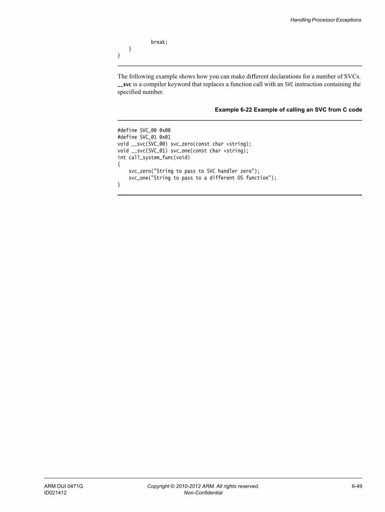
Handling Processor Exceptions
break;}
}
The following example shows how you can make different declarations for a number of SVCs. __svc is a compiler keyword that replaces a function call with an SVC instruction containing the specified number.
Example 6-22 Example of calling an SVC from C code
#define SVC_00 0x00#define SVC_01 0x01void __svc(SVC_00) svc_zero(const char *string);void __svc(SVC_01) svc_one(const char *string);int call_system_func(void){
svc_zero("String to pass to SVC handler zero");svc_one("String to pass to a different OS function");
}
ARM DUI 0471G Copyright © 2010-2012 ARM. All rights reserved. 6-49ID021412 Non-Confidential
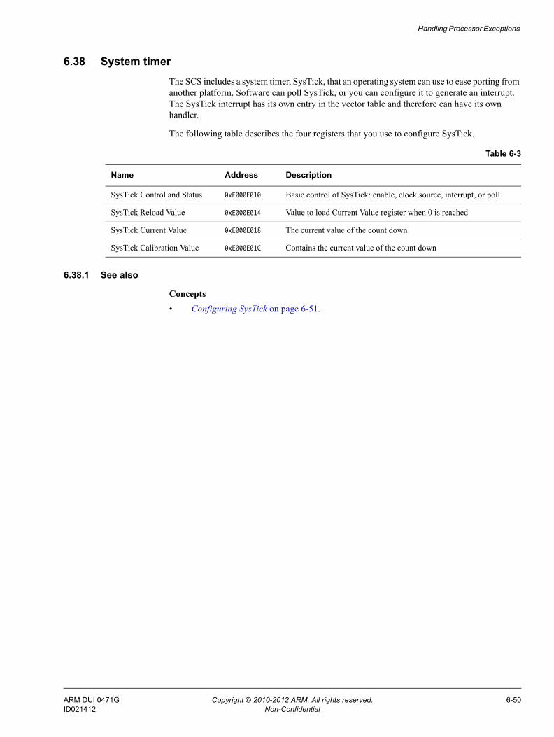
Handling Processor Exceptions
6.38 System timerThe SCS includes a system timer, SysTick, that an operating system can use to ease porting from another platform. Software can poll SysTick, or you can configure it to generate an interrupt. The SysTick interrupt has its own entry in the vector table and therefore can have its own handler.
The following table describes the four registers that you use to configure SysTick.
6.38.1 See also
Concepts • Configuring SysTick on page 6-51.
Table 6-3
Name Address Description
SysTick Control and Status 0xE000E010 Basic control of SysTick: enable, clock source, interrupt, or poll
SysTick Reload Value 0xE000E014 Value to load Current Value register when 0 is reached
SysTick Current Value 0xE000E018 The current value of the count down
SysTick Calibration Value 0xE000E01C Contains the current value of the count down
ARM DUI 0471G Copyright © 2010-2012 ARM. All rights reserved. 6-50ID021412 Non-Confidential

Handling Processor Exceptions
6.39 Configuring SysTickTo configure SysTick, load the interval required between SysTick events to the SysTick Reload Value register. The timer interrupt, or COUNTFLAG bit in the SysTick Control and Status register, is activated on the transition from 1 to 0, therefore it activates every n+1 clock ticks. If you require a period of 100, write 99 to the SysTick Reload Value register. The SysTick Reload Value register supports values between 0x1 and 0x00FFFFFF.
If you want to use SysTick to generate an event at a timed interval, for example 1ms, you can use the SysTick Calibration Value Register to scale your value for the Reload register. The SysTick Calibration Value Register is a read-only register that contains the number of pulses for a period of 10ms, in the TENMS field, bits[23:0].
This register also has a SKEW bit. Bit[30] == 1 indicates that the calibration for 10ms in the TENMS section is not exactly 10ms due to clock frequency. Bit[31] == 1 indicates that the reference clock is not provided.
Note For Cortex-M1 processors, the TENMS field reads as zero because the calibration value is unknown.
The Control and Status Register can poll the timer either by reading COUNTFLAG, bit[16] and the SysTick generating an interrupt.
By default, SysTick is configured for polling mode. In this mode, user code polls COUNTFLAG, to ascertain if the SysTick event had occurred. This is indicated by COUNTFLAG being set. Reading the Control and Status register clears COUNTFLAG. To configure SysTick to generate an interrupt, set TICKINT, bit[1] of the SysTick Control and Status register, to 1. You must also enable the appropriate interrupt in the NVIC, and select the clock source using CLKSOURCE, bit[2]. Setting this to 1 selects the processor clock, and 0 selects the external reference clock.
Note For ARMv6-M processors, the CLKSOURCE field reads as One because SysTick always uses the processor clock.
You can enable the timer by setting bit[0] of the SysTick Status and Control register.
ARM DUI 0471G Copyright © 2010-2012 ARM. All rights reserved. 6-51ID021412 Non-Confidential

Chapter 7 Debug Communications Channel
The following topics explain how to use the Debug Communications Channel (DCC):• About the Debug Communications Channel on page 7-2• DCC communication between target and host debug tools on page 7-3• Interrupt-driven debug communications on page 7-4• Access from Thumb state on page 7-6.
ARM DUI 0471G Copyright © 2010-2012 ARM. All rights reserved. 7-1ID021412 Non-Confidential

Debug Communications Channel
7.1 About the Debug Communications Channel
The EmbeddedICE® logic in ARM processors contains a debug communications channel. This enables data to be passed between the target and the host debug tools. This describes how the DCC can be accessed by a program running on the target, and by the host debugger.
7.1.1 See also
Concepts • DCC communication between target and host debug tools on page 7-3• Interrupt-driven debug communications on page 7-4• Access from Thumb state on page 7-6
ARM DUI 0471G Copyright © 2010-2012 ARM. All rights reserved. 7-2ID021412 Non-Confidential

Debug Communications Channel
7.2 DCC communication between target and host debug toolsThe target accesses the DCC as coprocessor 14 on the processor using the ARM instructions MCR and MRC. The following figure shows three DCC registers to control and transfer data between the target and host debug tools.
Read register For the target to read data sent from the host debug tools.
Write register For the target to write messages to the host debug tools.
Control register To provide handshaking information for the target and the host debug tools.For pre-ARMv6 processors:Bit 1 (W bit) Clear when the target can send data.Bit 0 (R bit) Set when there is data for the target to read.For ARMv6 and later processors:Bit 29 (W bit) Clear when the target can send data.Bit 30 (R bit) Set when there is data for the target to read.
Figure 7-1 DCC communication between target and host debug tools
7.2.1 See also
Other information • The Technical Reference Manual for your processor.
Scan chain 2
Write register
Read register
Control register JTAG DSTREAM
DCC Host debug tools
Target code
ARM DUI 0471G Copyright © 2010-2012 ARM. All rights reserved. 7-3ID021412 Non-Confidential

Debug Communications Channel
7.3 Interrupt-driven debug communicationsThe following example shows a code snippet that demonstrates a simple DCC routine. Text sent from the debug tools is echoed back from the target with a change of case. Build an executable image from this example and run it on your target using the JTAG port. See your debugger documentation for instructions on how to communicate with your target through DCC.
Example 7-1 DCC communication between target and host debug tools
;; Copyright ARM Ltd 2008. All rights reserved.
AREA DCC, CODE, READONLYENTRY
; Global Variables (for assembly time substitution)
GBLS SCReg ; Debug Status and Control Register name GBLS DReg ; Data Register name (same for reading and writing) GBLS TestFull ; R bit mask for testing whether the data register is ready to read from GBLS TestEmpty ; W bit mask for testing whether the data register is ready to write to
; select which architecture group to assemble for
IF :DEF:pre_v6 ; assemble for v6 and earlier processors INFO 0, "Assembling for pre_v6..."SCReg SETS "c0,c0"DReg SETS "c1,c0"TestFull SETS "#1"TestEmpty SETS "#2" ELIF :DEF:v6_onward ; assemble for v6 and onward processors INFO 0, "Assembling for v6_onward..."SCReg SETS "c0,c1"DReg SETS "c0,c5"TestFull SETS "#0x40000000"TestEmpty SETS "#0x20000000" ELSE INFO 1, "No target architecture specified. See the readme for moredetails." ENDIF
IF :DEF:pre_v6 || :DEF:v6_onward
; Code
pollin MRC p14,0,r3,$SCReg,0 ; Read Debug Status and Control RegisterTST r3, $TestFullBEQ pollin ; If R bit clear then loop
readMRC p14,0,r0,$DReg,0 ; read word into r0
char_masksMOV r4, #0x20 ; EOR mask to invert case of a char by flipping bit 6MOV r5, #0xC0 ; AND mask to clear all but top 2 bits of each char
ARM DUI 0471G Copyright © 2010-2012 ARM. All rights reserved. 7-4ID021412 Non-Confidential

Debug Communications Channel
changeCaseTST r0, r5 ; Check whether character value is >0x3FEORNE r0, r0, r4 ; If character value >0x3F, flip bit 6
; of the character to invert caseMOV r5, r5, LSL #0x8 ; Shift the character mask left by 1 charMOVS r4, r4, LSL #0x8 ; Shift the case inverter pattern left by 1 charBNE changeCase ; If the inverter pattern is non-zero there are
; more chars, so branch to do the next onepollout
MRC p14,0,r3,$SCReg,0 ; Read Debug Status and Control RegisterTST r3, $TestEmptyBNE pollout ; if W set, register still full
writeMCR p14,0,r0,$DReg,0 ; Write word from r0B pollin ; Loop for more words to read
ENDIF
END
You can convert this type of polled example to an interrupt-driven example if COMMRX and COMMTX signals from the Embedded ICE logic are connected to your interrupt controller. The read and write code can then be used in an interrupt handler.
Suggest you put in an example of how to build this code example, like you’ve done in other topics:
• To build for v6 and onward output:armasm --predefine "v6_onward SETL {TRUE}" -g dcc.sarmlink dcc.o -o dcc.axf --ro-base=0x8000
• To build for pre-v6 output:To build for pre-v6 outputarmasm --predefine "pre_v6 SETL {TRUE}" -g dcc.sarmlink dcc.o -o dcc.axf --ro-base=0x8000
7.3.1 See also
Reference • Interrupt handlers and levels of external interrupt on page 6-13.Assembler Reference:• --debug on page 2-9• -g on page 2-16• --predefine "directive" on page 2-21.Linker Reference:• --output=filename on page 2-114• --ro_base=address on page 2-135.
ARM DUI 0471G Copyright © 2010-2012 ARM. All rights reserved. 7-5ID021412 Non-Confidential

Debug Communications Channel
7.4 Access from Thumb stateOn processors with architecture earlier than the ARM architecture v6T2, you cannot use the debug communications channel while the processor is in Thumb state, because there are no Thumb coprocessor instructions.
There are three possible ways around this:
• You can write each polling routine in a SVC handler, which can then be invoked while in either ARM or Thumb state. Entering the SVC handler immediately puts the processor into ARM state where the coprocessor instructions are available.
• Thumb code can make interworking calls to ARM subroutines that implement the polling.
• Use interrupt-driven communication rather than polled communication. The interrupt handler runs in ARM state, so the coprocessor instructions can be accessed directly.
7.4.1 See also
Concepts • Chapter 5 Interworking ARM and Thumb• Chapter 6 Handling Processor Exceptions.
ARM DUI 0471G Copyright © 2010-2012 ARM. All rights reserved. 7-6ID021412 Non-Confidential

Chapter 8 Semihosting
The following topics describe the semihosting mechanism:• What is semihosting? on page 8-3• The semihosting interface on page 8-5• Can I change the semihosting operation numbers? on page 8-7• Semihosting operations on page 8-8• Debug agent interaction SVCs on page 8-9• angel_SWIreason_EnterSVC (0x17) on page 8-10• angel_SWIreason_ReportException (0x18) on page 8-11• SYS_CLOSE (0x02) on page 8-13• SYS_CLOCK (0x10) on page 8-14• SYS_ELAPSED (0x30) on page 8-15• SYS_ERRNO (0x13) on page 8-16• SYS_FLEN (0x0C) on page 8-17• SYS_GET_CMDLINE (0x15) on page 8-18• SYS_HEAPINFO (0x16) on page 8-19• SYS_ISERROR (0x08) on page 8-20• SYS_ISTTY (0x09) on page 8-21• SYS_OPEN (0x01) on page 8-22• SYS_READ (0x06) on page 8-23• SYS_READC (0x07) on page 8-24• SYS_REMOVE (0x0E) on page 8-25• SYS_RENAME (0x0F) on page 8-26• SYS_SEEK (0x0A) on page 8-27
ARM DUI 0471G Copyright © 2010-2012 ARM. All rights reserved. 8-1ID021412 Non-Confidential

Semihosting
• SYS_SYSTEM (0x12) on page 8-28• SYS_TICKFREQ (0x31) on page 8-29• SYS_TIME (0x11) on page 8-30• SYS_TMPNAM (0x0D) on page 8-31• SYS_WRITE (0x05) on page 8-32• SYS_WRITEC (0x03) on page 8-33• SYS_WRITE0 (0x04) on page 8-34.
ARM DUI 0471G Copyright © 2010-2012 ARM. All rights reserved. 8-2ID021412 Non-Confidential

Semihosting
8.1 What is semihosting?Semihosting is a mechanism that enables code running on an ARM target to communicate and use the Input/Output facilities on a host computer that is running a debugger.
Examples of these facilities include keyboard input, screen output, and disk I/O. For example, you can use this mechanism to enable functions in the C library, such as printf() and scanf(), to use the screen and keyboard of the host instead of having a screen and keyboard on the target system.
This is useful because development hardware often does not have all the input and output facilities of the final system. Semihosting enables the host computer to provide these facilities.
Semihosting is implemented by a set of defined software instructions, for example, SVCs, that generate exceptions from program control. The application invokes the appropriate semihosting call and the debug agent then handles the exception. The debug agent provides the required communication with the host.
The semihosting interface is common across all debug agents provided by ARM. Semihosted operations work when you are debugging applications on your development platform, as shown in the following figure:
Figure 8-1 Semihosting overview
In many cases, semihosting is invoked by code within library functions. The application can also invoke the semihosting operation directly.
Note ARM processors prior to ARMv7 use the SVC instructions, formerly known as SWI instructions, to make semihosting calls. However, if you are compiling for an ARMv6-M or ARMv7-M, for example a Cortex-M1 or Cortex-M3 processor, semihosting is implemented using the BKPT instruction.
8.1.1 See also
Concepts • The semihosting interface on page 8-5• Can I change the semihosting operation numbers? on page 8-7.
SVC C Library Code
debugger
Target
Host
printf()
hello
printf(“hello\n”);
Text displayed on host screen
Application Code
SVC handled by debug agent
Communication with debugger running on host
ARM DUI 0471G Copyright © 2010-2012 ARM. All rights reserved. 8-3ID021412 Non-Confidential

Semihosting
Using ARM C and C++ Libraries and Floating Point Support:• Chapter 2 The ARM C and C++ libraries.
Reference • Semihosting operations on page 8-8• Debug agent interaction SVCs on page 8-9
ARM DUI 0471G Copyright © 2010-2012 ARM. All rights reserved. 8-4ID021412 Non-Confidential

Semihosting
8.2 The semihosting interfaceThe ARM and Thumb SVC instructions contain a field that encodes the SVC number used by the application code. The system SVC handler can decode this number.
Note If you are compiling for the ARMv6-M or ARMv7-M, the Thumb BKPT instruction is used instead of the Thumb SVC instruction. Both BKPT and SVC take an 8-bit immediate value. In all other respects, semihosting is the same for all supported ARM processors.
Semihosting operations are requested using a single SVC number, leaving the other numbers available for use by the application or operating system. The SVC number used for semihosting depends on the target architecture or processor:
SVC 0x123456 In ARM state for all architectures.
SVC 0xAB In ARM state and Thumb state, excluding ARMv6-M and ARMv7-M. This behavior is not guaranteed on all debug targets from ARM or from third parties.
BKPT 0xAB For ARMv6-M and ARMv7-M, Thumb state only.
The SVC number indicates to the debug agent that the SVC instruction is a semihosting request. To distinguish between operations, the operation type is passed in R0. All other parameters are passed in a block that is pointed to by R1.
The result is returned in R0, either as an explicit return value or as a pointer to a data block. Even if no result is returned, assume that R0 is corrupted.
The available semihosting operation numbers passed in R0 are allocated as follows:
0x00-0x31 Used by ARM.
0x32-0xFF Reserved for future use by ARM.
0x100-0x1FF Reserved for user applications. These are not used by ARM.If you are writing your own SVC operations, however, you are advised to use a different SVC number rather than using the semihosted SVC number and these operation type numbers.
0x200-0xFFFFFFFF Undefined and currently unused. It is recommended that you do not use these.
In the following sections, the number in parentheses after the operation name is the value placed into R0, for example SYS_OPEN (0x01).
If you are calling SVCs from assembly language code ARM recommends that you define the semihosting operation names, to their respective operation numbers, with the EQU directive. For example:
SYS_OPEN EQU 0x01SYS_CLOSE EQU 0x02
8.2.1 See also
Concepts • What is semihosting? on page 8-3• Can I change the semihosting operation numbers? on page 8-7.
ARM DUI 0471G Copyright © 2010-2012 ARM. All rights reserved. 8-5ID021412 Non-Confidential

Semihosting
Reference • Semihosting operations on page 8-8• Debug agent interaction SVCs on page 8-9
ARM DUI 0471G Copyright © 2010-2012 ARM. All rights reserved. 8-6ID021412 Non-Confidential

Semihosting
8.3 Can I change the semihosting operation numbers?It is strongly recommended that you do not change the semihosting operation numbers. However, if you have to do this, you must:• change all the code in your system, including library code, to use the new number• reconfigure your debugger to use the new number.
8.3.1 See also
Concepts • What is semihosting? on page 8-3• The semihosting interface on page 8-5.
ARM DUI 0471G Copyright © 2010-2012 ARM. All rights reserved. 8-7ID021412 Non-Confidential
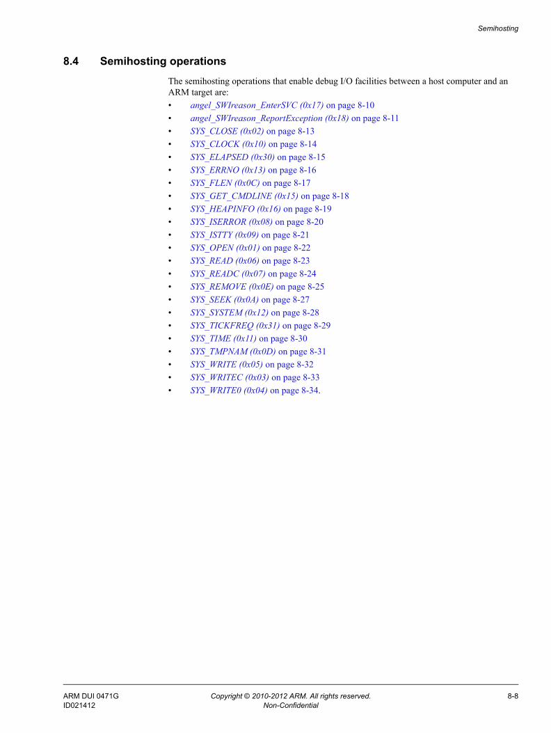
Semihosting
8.4 Semihosting operationsThe semihosting operations that enable debug I/O facilities between a host computer and an ARM target are:• angel_SWIreason_EnterSVC (0x17) on page 8-10• angel_SWIreason_ReportException (0x18) on page 8-11• SYS_CLOSE (0x02) on page 8-13• SYS_CLOCK (0x10) on page 8-14• SYS_ELAPSED (0x30) on page 8-15• SYS_ERRNO (0x13) on page 8-16• SYS_FLEN (0x0C) on page 8-17• SYS_GET_CMDLINE (0x15) on page 8-18• SYS_HEAPINFO (0x16) on page 8-19• SYS_ISERROR (0x08) on page 8-20• SYS_ISTTY (0x09) on page 8-21• SYS_OPEN (0x01) on page 8-22• SYS_READ (0x06) on page 8-23• SYS_READC (0x07) on page 8-24• SYS_REMOVE (0x0E) on page 8-25• SYS_SEEK (0x0A) on page 8-27• SYS_SYSTEM (0x12) on page 8-28• SYS_TICKFREQ (0x31) on page 8-29• SYS_TIME (0x11) on page 8-30• SYS_TMPNAM (0x0D) on page 8-31• SYS_WRITE (0x05) on page 8-32• SYS_WRITEC (0x03) on page 8-33• SYS_WRITE0 (0x04) on page 8-34.
ARM DUI 0471G Copyright © 2010-2012 ARM. All rights reserved. 8-8ID021412 Non-Confidential

Semihosting
8.5 Debug agent interaction SVCsIn addition to the C library semihosted functions, the following SVCs support interaction with the debug agent:• angel_SWIreason_EnterSVC (0x17)• angel_SWIreason_ReportException (0x18).
8.5.1 See also
Reference • Semihosting operations on page 8-8• angel_SWIreason_EnterSVC (0x17) on page 8-10• angel_SWIreason_ReportException (0x18) on page 8-11.
ARM DUI 0471G Copyright © 2010-2012 ARM. All rights reserved. 8-9ID021412 Non-Confidential

Semihosting
8.6 angel_SWIreason_EnterSVC (0x17)
Sets the processor to Supervisor mode and disables all interrupts by setting both interrupt mask bits in the new CPSR. With a debug hardware unit, such as ARM RVI™ debug unit or ARM DSTREAM™ debug and trace unit:• the User stack pointer, R13_USR, is copied to the Supervisor mode stack pointer, R13_SVC • the I and F bits in the current CPSR are set, which disables normal and fast interrupts.
8.6.1 Entry
Register R1 is not used. The CPSR can specify User or Supervisor mode.
8.6.2 Return
On exit, R0 contains the address of a function to be called to return to User mode. The function has the following prototype:
void ReturnToUSR(void)
If EnterSVC is called in User mode, this routine returns the caller to User mode and restores the interrupt flags. Otherwise, the action of this routine is undefined.
If entered in User mode, the Supervisor mode stack is lost as a result of copying the user stack pointer. The return to User routine restores R13_SVC to the Supervisor mode stack value, but this stack must not be used by applications.
After executing the SVC, the current link register is R14_SVC, not R14_USR. If the value of R14_USR is required after the call, it must be pushed onto the stack before the call and popped afterwards, as for a BL function call.
ARM DUI 0471G Copyright © 2010-2012 ARM. All rights reserved. 8-10ID021412 Non-Confidential

Semihosting
8.7 angel_SWIreason_ReportException (0x18)
This SVC can be called by an application to report an exception to the debugger directly. The most common use is to report that execution has completed, using ADP_Stopped_ApplicationExit.
8.7.1 Entry
On entry R1 is set to one of the values listed in the following tables. These values are defined in angel_reasons.h.
The hardware exceptions are generated if the debugger variable vector_catch is set to catch that exception type, and the debug agent is capable of reporting that exception type. The following table shows the hardware vector reason codes:
Exception handlers can use these SVCs at the end of handler chains as the default action, to indicate that the exception has not been handled. The following table shows the software reason codes:
Table 8-1 Hardware vector reason codes
Name Hexadecimalvalue
ADP_Stopped_BranchThroughZero 0x20000
ADP_Stopped_UndefinedInstr 0x20001
ADP_Stopped_SoftwareInterrupt 0x20002
ADP_Stopped_PrefetchAbort 0x20003
ADP_Stopped_DataAbort 0x20004
ADP_Stopped_AddressException 0x20005
ADP_Stopped_IRQ 0x20006
ADP_Stopped_FIQ 0x20007
Table 8-2 Software reason codes
Name Hexadecimalvalue
ADP_Stopped_BreakPoint 0x20020
ADP_Stopped_WatchPoint 0x20021
ADP_Stopped_StepComplete 0x20022
ADP_Stopped_RunTimeErrorUnknown *0x20023
ADP_Stopped_InternalError *0x20024
ADP_Stopped_UserInterruption 0x20025
ADP_Stopped_ApplicationExit 0x20026
ARM DUI 0471G Copyright © 2010-2012 ARM. All rights reserved. 8-11ID021412 Non-Confidential

Semihosting
In this table, a * next to a value indicates that the value is not supported by the ARM debugger. The debugger reports an Unhandled ADP_Stopped exception for these values.
8.7.2 Return
No return is expected from these calls. However, it is possible for the debugger to request that the application continue by performing an RDI_Execute request or equivalent. In this case, execution continues with the registers as they were on entry to the SVC, or as subsequently modified by the debugger.
ADP_Stopped_StackOverflow *0x20027
ADP_Stopped_DivisionByZero *0x20028
ADP_Stopped_OSSpecific *0x20029
Table 8-2 Software reason codes (continued)
Name Hexadecimalvalue
ARM DUI 0471G Copyright © 2010-2012 ARM. All rights reserved. 8-12ID021412 Non-Confidential

Semihosting
8.8 SYS_CLOSE (0x02)
Closes a file on the host system. The handle must reference a file that was opened with SYS_OPEN.
8.8.1 Entry
On entry, R1 contains a pointer to a one-word argument block:
word 1 contains a handle for an open file.
8.8.2 Return
On exit, R0 contains:• 0 if the call is successful• –1 if the call is not successful.
8.8.3 See also
Reference • SYS_OPEN (0x01) on page 8-22.
ARM DUI 0471G Copyright © 2010-2012 ARM. All rights reserved. 8-13ID021412 Non-Confidential

Semihosting
8.9 SYS_CLOCK (0x10)
Returns the number of centiseconds since the execution started.
Values returned by this SVC can be of limited use for some benchmarking purposes because of communication overhead or other agent-specific factors. For example, with a debug hardware unit, such as RVI or DSTREAM, the request is passed back to the host for execution. This can lead to unpredictable delays in transmission and process scheduling.
Use this function to calculate time intervals, by calculating differences between intervals with and without the code sequence to be timed.
8.9.1 Entry
Register R1 must contain zero. There are no other parameters.
8.9.2 Return
On exit, R0 contains:• the number of centiseconds since some arbitrary start point, if the call is successful• –1 if the call is not successful, for example, because of a communications error.
8.9.3 See also
Concepts • SYS_ELAPSED (0x30) on page 8-15• SYS_TICKFREQ (0x31) on page 8-29.
ARM DUI 0471G Copyright © 2010-2012 ARM. All rights reserved. 8-14ID021412 Non-Confidential
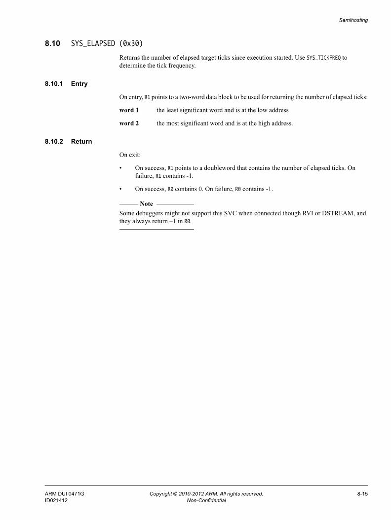
Semihosting
8.10 SYS_ELAPSED (0x30)
Returns the number of elapsed target ticks since execution started. Use SYS_TICKFREQ to determine the tick frequency.
8.10.1 Entry
On entry, R1 points to a two-word data block to be used for returning the number of elapsed ticks:
word 1 the least significant word and is at the low address
word 2 the most significant word and is at the high address.
8.10.2 Return
On exit:
• On success, R1 points to a doubleword that contains the number of elapsed ticks. On failure, R1 contains -1.
• On success, R0 contains 0. On failure, R0 contains -1.
Note Some debuggers might not support this SVC when connected though RVI or DSTREAM, and they always return –1 in R0.
ARM DUI 0471G Copyright © 2010-2012 ARM. All rights reserved. 8-15ID021412 Non-Confidential

Semihosting
8.11 SYS_ERRNO (0x13)
Returns the value of the C library errno variable associated with the host implementation of the semihosting SVCs. The errno variable can be set by a number of C library semihosted functions, including:• SYS_REMOVE
• SYS_OPEN
• SYS_CLOSE
• SYS_READ
• SYS_WRITE
• SYS_SEEK.
Whether errno is set or not, and to what value, is entirely host-specific, except where the ISO C standard defines the behavior.
8.11.1 Entry
There are no parameters. Register R1 must be zero.
8.11.2 Return
On exit, R0 contains the value of the C library errno variable.
8.11.3 See also
Reference • SYS_CLOSE (0x02) on page 8-13• SYS_OPEN (0x01) on page 8-22• SYS_READ (0x06) on page 8-23• SYS_REMOVE (0x0E) on page 8-25• SYS_SEEK (0x0A) on page 8-27• SYS_WRITE (0x05) on page 8-32.
ARM DUI 0471G Copyright © 2010-2012 ARM. All rights reserved. 8-16ID021412 Non-Confidential
Semihosting
8.12 SYS_FLEN (0x0C)
Returns the length of a specified file.
8.12.1 Entry
On entry, R1 contains a pointer to a one-word argument block:
word 1 A handle for a previously opened, seekable file object.
8.12.2 Return
On exit, R0 contains:• the current length of the file object, if the call is successful• –1 if an error occurs.
ARM DUI 0471G Copyright © 2010-2012 ARM. All rights reserved. 8-17ID021412 Non-Confidential

Semihosting
8.13 SYS_GET_CMDLINE (0x15)
Returns the command line used to call the executable, that is, argc and argv.
8.13.1 Entry
On entry, R1 points to a two-word data block to be used for returning the command string and its length:
word 1 a pointer to a buffer of at least the size specified in word two
word 2 the length of the buffer in bytes.
8.13.2 Return
On exit:
• Register R1 points to a two-word data block:word 1 a pointer to null-terminated string of the command lineword 2 the length of the string.The debug agent might impose limits on the maximum length of the string that can be transferred. However, the agent must be able to transfer a command line of at least 80 bytes.
• Register R0 contains an error code:— 0 if the call is successful— –1 if the call is not successful, for example, because of a communications error.
ARM DUI 0471G Copyright © 2010-2012 ARM. All rights reserved. 8-18ID021412 Non-Confidential

Semihosting
8.14 SYS_HEAPINFO (0x16)
Returns the system stack and heap parameters. The values returned are typically those used by the C library during initialization. For a debug hardware unit, such as RVI or DSTREAM, the values returned are the image location and the top of memory.
The C library can override these values.
The host debugger determines the actual values to return by using the top_of_memory debugger variable.
8.14.1 Entry
On entry, R1 contains the address of a pointer to a four-word data block. The contents of the data block are filled by the function. The following example shows the structure of the data block and return values.
Example 8-1
struct block { int heap_base; int heap_limit; int stack_base; int stack_limit;};struct block *mem_block, info;mem_block = &info;AngelSWI(SYS_HEAPINFO, (unsigned) &mem_block);
Note If word one of the data block has the value zero, the C library replaces the zero with Image$$ZI$$Limit. This value corresponds to the top of the data region in the memory map.
8.14.2 Return
On exit, R1 contains the address of the pointer to the structure.
If one of the values in the structure is 0, the system was unable to calculate the real value.
ARM DUI 0471G Copyright © 2010-2012 ARM. All rights reserved. 8-19ID021412 Non-Confidential

Semihosting
8.15 SYS_ISERROR (0x08)
Determines whether the return code from another semihosting call is an error status or not. This call is passed a parameter block containing the error code to examine.
8.15.1 Entry
On entry, R1 contains a pointer to a one-word data block:
word 1 The required status word to check.
8.15.2 Return
On exit, R0 contains:• 0 if the status word is not an error indication• a nonzero value if the status word is an error indication.
ARM DUI 0471G Copyright © 2010-2012 ARM. All rights reserved. 8-20ID021412 Non-Confidential

Semihosting
8.16 SYS_ISTTY (0x09)
Checks whether a file is connected to an interactive device.
8.16.1 Entry
On entry, R1 contains a pointer to a one-word argument block:
word 1 A handle for a previously opened file object.
8.16.2 Return
On exit, R0 contains:• 1 if the handle identifies an interactive device• 0 if the handle identifies a file• a value other than 1 or 0 if an error occurs.
ARM DUI 0471G Copyright © 2010-2012 ARM. All rights reserved. 8-21ID021412 Non-Confidential

Semihosting
8.17 SYS_OPEN (0x01)
Opens a file on the host system. The file path is specified either as relative to the current directory of the host process, or absolute, using the path conventions of the host operating system.
ARM targets interpret the special path name :tt as meaning the console input stream, for an open-read or the console output stream, for an open-write. Opening these streams is performed as part of the standard startup code for those applications that reference the C stdio streams.
8.17.1 Entry
On entry, R1 contains a pointer to a three-word argument block:
word 1 A pointer to a null-terminated string containing a file or device name.
word 2 An integer that specifies the file opening mode. The following table gives the valid values for the integer, and their corresponding ISO C fopen() mode.
word 3 An integer that gives the length of the string pointed to by word 1. The length does not include the terminating null character that must be present.
8.17.2 Return
On exit, R0 contains:• a nonzero handle if the call is successful• –1 if the call is not successful.
Table 8-3 Value of mode
mode 0 1 2 3 4 5 6 7 8 9 10 11
ISO C fopen modea
a. The non-ANSI option t is not supported.
r rb r+ r+b w wb w+ w+b a ab a+ a+b
ARM DUI 0471G Copyright © 2010-2012 ARM. All rights reserved. 8-22ID021412 Non-Confidential

Semihosting
8.18 SYS_READ (0x06)
Reads the contents of a file into a buffer. The file position is specified either:• explicitly by a SYS_SEEK• implicitly one byte beyond the previous SYS_READ or SYS_WRITE request.
The file position is at the start of the file when the file is opened, and is lost when the file is closed. Perform the file operation as a single action whenever possible. For example, do not split a read of 16KB into four 4KB chunks unless there is no alternative.
8.18.1 Entry
On entry, R1 contains a pointer to a four-word data block:word 1 contains a handle for a file previously opened with SYS_OPENword 2 points to a bufferword 3 contains the number of bytes to read to the buffer from the file.
8.18.2 Return
On exit:
• R0 contains zero if the call is successful.
• If R0 contains the same value as word 3, the call has failed and EOF is assumed.
• If R0 contains a smaller value than word 3, the call was partially successful. No error is assumed, but the buffer has not been filled.
If the handle is for an interactive device, that is, SYS_ISTTY returns –1. A nonzero return from SYS_READ indicates that the line read did not fill the buffer.
ARM DUI 0471G Copyright © 2010-2012 ARM. All rights reserved. 8-23ID021412 Non-Confidential

Semihosting
8.19 SYS_READC (0x07)
Reads a byte from the console.
8.19.1 Entry
Register R1 must contain zero. There are no other parameters or values possible.
8.19.2 Return
On exit, R0 contains the byte read from the console.
ARM DUI 0471G Copyright © 2010-2012 ARM. All rights reserved. 8-24ID021412 Non-Confidential
Semihosting
8.20 SYS_REMOVE (0x0E)
Caution Deletes a specified file on the host filing system.
8.20.1 Entry
On entry, R1 contains a pointer to a two-word argument block:
word 1 points to a null-terminated string that gives the path name of the file to be deleted
word 2 the length of the string.
8.20.2 Return
On exit, R0 contains:• 0 if the delete is successful• a nonzero, host-specific error code if the delete fails.
ARM DUI 0471G Copyright © 2010-2012 ARM. All rights reserved. 8-25ID021412 Non-Confidential

Semihosting
8.21 SYS_RENAME (0x0F)
Renames a specified file.
8.21.1 Entry
On entry, R1 contains a pointer to a four-word data block:word 1 a pointer to the name of the old fileword 2 the length of the old filenameword 3 a pointer to the new filenameword 4 the length of the new filename.
Both strings are null-terminated.
8.21.2 Return
On exit, R0 contains:• 0 if the rename is successful• a nonzero, host-specific error code if the rename fails.
ARM DUI 0471G Copyright © 2010-2012 ARM. All rights reserved. 8-26ID021412 Non-Confidential

Semihosting
8.22 SYS_SEEK (0x0A)
Seeks to a specified position in a file using an offset specified from the start of the file. The file is assumed to be a byte array and the offset is given in bytes.
8.22.1 Entry
On entry, R1 contains a pointer to a two-word data block:word 1 a handle for a seekable file objectword 2 the absolute byte position to search to.
8.22.2 Return
On exit, R0 contains:
• 0 if the request is successful
• A negative value if the request is not successful. SYS_ERRNO can be used to read the value of the host errno variable describing the error.
Note The effect of seeking outside the current extent of the file object is undefined.
ARM DUI 0471G Copyright © 2010-2012 ARM. All rights reserved. 8-27ID021412 Non-Confidential

Semihosting
8.23 SYS_SYSTEM (0x12)
Passes a command to the host command-line interpreter. This enables you to execute a system command such as dir, ls, or pwd. The terminal I/O is on the host, and is not visible to the target.
Caution The command passed to the host is executed on the host. Ensure that any command passed has no unintended consequences.
8.23.1 Entry
On entry, R1 contains a pointer to a two-word argument block:word 1 points to a string to be passed to the host command-line interpreterword 2 the length of the string.
8.23.2 Return
On exit, R0 contains the return status.
ARM DUI 0471G Copyright © 2010-2012 ARM. All rights reserved. 8-28ID021412 Non-Confidential
Semihosting
8.24 SYS_TICKFREQ (0x31)
Returns the tick frequency.
8.24.1 Entry
Register R1 must contain 0 on entry to this routine.
8.24.2 Return
On exit, R0 contains either:
• the number of ticks per second
• –1 if the target does not know the value of one tick. Some debuggers might not support this SVC when connected though RVI or DSTREAM and they always return –1 in R0.
ARM DUI 0471G Copyright © 2010-2012 ARM. All rights reserved. 8-29ID021412 Non-Confidential

Semihosting
8.25 SYS_TIME (0x11)
Returns the number of seconds since 00:00 January 1, 1970. This is real-world time, regardless of any debug agent configuration, such as RVI or DSTREAM.
8.25.1 Entry
There are no parameters.
8.25.2 Return
On exit, R0 contains the number of seconds.
ARM DUI 0471G Copyright © 2010-2012 ARM. All rights reserved. 8-30ID021412 Non-Confidential

Semihosting
8.26 SYS_TMPNAM (0x0D)
Returns a temporary name for a file identified by a system file identifier.
8.26.1 Entry
On entry, R1 contains a pointer to a three-word argument block:
word 1 A pointer to a buffer.
word 2 A target identifier for this filename. Its value must be an integer in the range 0 to 255.
word 3 Contains the length of the buffer. The length must be at least the value of L_tmpnam on the host system.
8.26.2 Return
On exit, R0 contains:• 0 if the call is successful• –1 if an error occurs.
The buffer pointed to by R1 contains the filename, prefixed with a suitable directory name.
If you use the same target identifier again, the same filename is returned.
Note The returned string must be null-terminated.
ARM DUI 0471G Copyright © 2010-2012 ARM. All rights reserved. 8-31ID021412 Non-Confidential

Semihosting
8.27 SYS_WRITE (0x05)
Writes the contents of a buffer to a specified file at the current file position. The file position is specified either:• explicitly, by a SYS_SEEK• implicitly as one byte beyond the previous SYS_READ or SYS_WRITE request.
The file position is at the start of the file when the file is opened, and is lost when the file is closed.
Perform the file operation as a single action whenever possible. For example, do not split a write of 16KB into four 4KB chunks unless there is no alternative.
8.27.1 Entry
On entry, R1 contains a pointer to a three-word data block:word 1 contains a handle for a file previously opened with SYS_OPENword 2 points to the memory containing the data to be writtenword 3 contains the number of bytes to be written from the buffer to the file.
8.27.2 Return
On exit, R0 contains:• 0 if the call is successful• the number of bytes that are not written, if there is an error.
ARM DUI 0471G Copyright © 2010-2012 ARM. All rights reserved. 8-32ID021412 Non-Confidential

Semihosting
8.28 SYS_WRITEC (0x03)
Writes a character byte, pointed to by R1, to the debug channel. When executed under an ARM debugger, the character appears on the host debugger console.
8.28.1 Entry
On entry, R1 contains a pointer to the character.
8.28.2 Return
None. Register R0 is corrupted.
ARM DUI 0471G Copyright © 2010-2012 ARM. All rights reserved. 8-33ID021412 Non-Confidential
Semihosting
8.29 SYS_WRITE0 (0x04)
Writes a null-terminated string to the debug channel. When executed under an ARM debugger, the characters appear on the host debugger console.
8.29.1 Entry
On entry, R1 contains a pointer to the first byte of the string.
8.29.2 Return
None. Register R0 is corrupted.
ARM DUI 0471G Copyright © 2010-2012 ARM. All rights reserved. 8-34ID021412 Non-Confidential

Appendix A Revisions for Developing Software for ARM Processors
The following technical changes have been made to Developing Software for ARM Processors.
Table A-1 Differences between issue F and issue G
Change Topics affected
Added Cortex-A7 to the table of key features for the current ARM processors.
About the ARM architectures on page 2-2
Table A-2 Differences between issue D and issue F
Change Topics affected
Where appropriate:• prefixed Thumb with 16-bit• changed Thumb-2 to 32-bit Thumb• changed Thumb-2EE to ThumbEE.
Various topics
ARM DUI 0471G Copyright © 2010-2012 ARM. All rights reserved. A-1ID021412 Non-Confidential

Revisions for Developing Software for ARM Processors
Table A-3 Differences between issue C and issue D
Change Topics affected
Added Cortex-A15 and Cortex-R7 to the processor list. About the ARM architectures on page 2-2
Removed ARMulator ISS from document for ARM Compiler 5.0.
• angel_SWIreason_EnterSVC (0x17) on page 8-10• SYS_HEAPINFO (0x16) on page 8-19• The semihosting interface on page 8-5
Removed DCD 0 for reserved vector. Vector table for ARMv6 and earlier, ARMv7-A and ARMv7-R profiles on page 6-6
Added ARM Glossary to other information. Chapter 1 Conventions and feedback
Table A-4 Differences between issue B and issue C
Change Topics affected
Abbreviated RealView ICE to RVI. Also, mentioned DSTREAM when mentioning RVI.
• angel_SWIreason_EnterSVC (0x17) on page 8-10• SYS_CLOCK (0x10) on page 8-14• SYS_ELAPSED (0x30) on page 8-15• SYS_HEAPINFO (0x16) on page 8-19• SYS_TICKFREQ (0x31) on page 8-29• SYS_TIME (0x11) on page 8-30.
Table A-5 Differences between issue A and issue B
Change Topics affected
Added note that the overall layout of the memory maps of devices based around the ARMv6-M and ARMv7-M architectures are fixed.
Tailoring the image memory map to your target hardware on page 3-10
Added links to Scatter-loading file with link to bit-band objects, ARMARMv7-M, and ARMARMv6-M.
Tailoring the image memory map to your target hardware on page 3-10
Added links to Scatter-loading file with link to bit-band objects.
Scatter-loading description file on page 3-11
Added a new topic called Scatter-loading file with link to bit-band objects.
Scatter-loading file with link to bit-band objects on page 3-16
For SYS_ELAPSED, clarified that R0 contains 0 on success and -1 on failure.
SYS_ELAPSED (0x30) on page 8-15
Clarified that the linker uses a version of the library setup code rather than the __user_initial_stackheap() function when tailoring the stack and heap placement in the scatter-loading file.
Reset and initialization on page 3-17
ARM DUI 0471G Copyright © 2010-2012 ARM. All rights reserved. A-2ID021412 Non-Confidential