ARIEL Design, Development, Verification and Engineering Plan · ARIEL Payload Consortium ARIEL...
38
ARIEL Payload Consortium ARIEL Design, Development, Verification and Engineering Plan Doc Ref: ARIEL-RAL-PL-PL-002 Issue: 1.0 Date: 11 February 2017 ARIEL Design, Development, Verification and Engineering Plan Page i ARIEL Consortium Phase A Payload Study ARIEL Design, Development, Verification and Engineering Plan ARIEL-RAL-PL-PL-002 Issue 1.0 Prepared by: Date: Georgia Bishop (RAL Space) Systems Engineer Reviewed by: Date: Kevin Middleton (RAL Space) ARIEL Payload Systems Engineer Approved & Released by: Date: Paul Eccleston (RAL Space) Consortium Project Manager
Transcript of ARIEL Design, Development, Verification and Engineering Plan · ARIEL Payload Consortium ARIEL...
ARIEL Payload
Consortium ARIEL Design,
Development, Verification and Engineering Plan
Doc Ref: ARIEL-RAL-PL-PL-002 Issue: 1.0 Date: 11 February 2017
ARIEL Design, Development, Verification and Engineering Plan Page i
ARIEL Consortium Phase A Payload
Study
ARIEL Design, Development, Verification and Engineering
Plan ARIEL-RAL-PL-PL-002
Issue 1.0
Prepared by: Date:
Georgia Bishop (RAL Space) Systems Engineer
Reviewed by: Date: Kevin Middleton (RAL Space) ARIEL Payload Systems Engineer
Approved & Released by:
Date:
Paul Eccleston (RAL Space) Consortium Project Manager
pe73
Typewritten Text
pp
ARIEL Payload
Consortium ARIEL Design,
Development, Verification and Engineering Plan
Doc Ref: ARIEL-RAL-PL-PL-002 Issue: 1.0 Date: 11 February 2017
ARIEL Design Development Engineering and Verification Plan Page ii
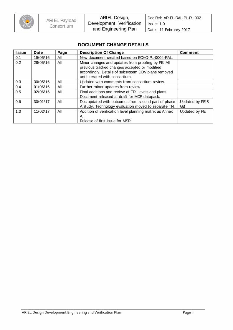
DOCUMENT CHANGE DETAILS Issue Date Page Description Of Change Comment 0.1 19/05/16 All New document created based on ECHO-PL-0004-RAL. 0.2 28/05/16 All Minor changes and updates from proofing by PE. All
previous tracked changes accepted or modified accordingly. Details of subsystem DDV plans removed until iterated with consortium.
0.3 30/05/16 All Updated with comments from consortium review. 0.4 01/06/16 All Further minor updates from review 0.5 02/06/16 All Final additions and review of TRL levels and plans.
Document released at draft for MCR datapack.
0.6 30/01/17 All Doc updated with outcomes from second part of phase A study. Technology evaluation moved to separate TN.
Updated by PE & GB
1.0 11/02/17 All Addition of verification level planning matrix as Annex A. Release of first issue for MSR
Updated by PE
ARIEL Payload
Consortium ARIEL Design,
Development, Verification and Engineering Plan
Doc Ref: ARIEL-RAL-PL-PL-002 Issue: 1.0 Date: 11 February 2017
ARIEL Design Development Engineering and Verification Plan Page iii
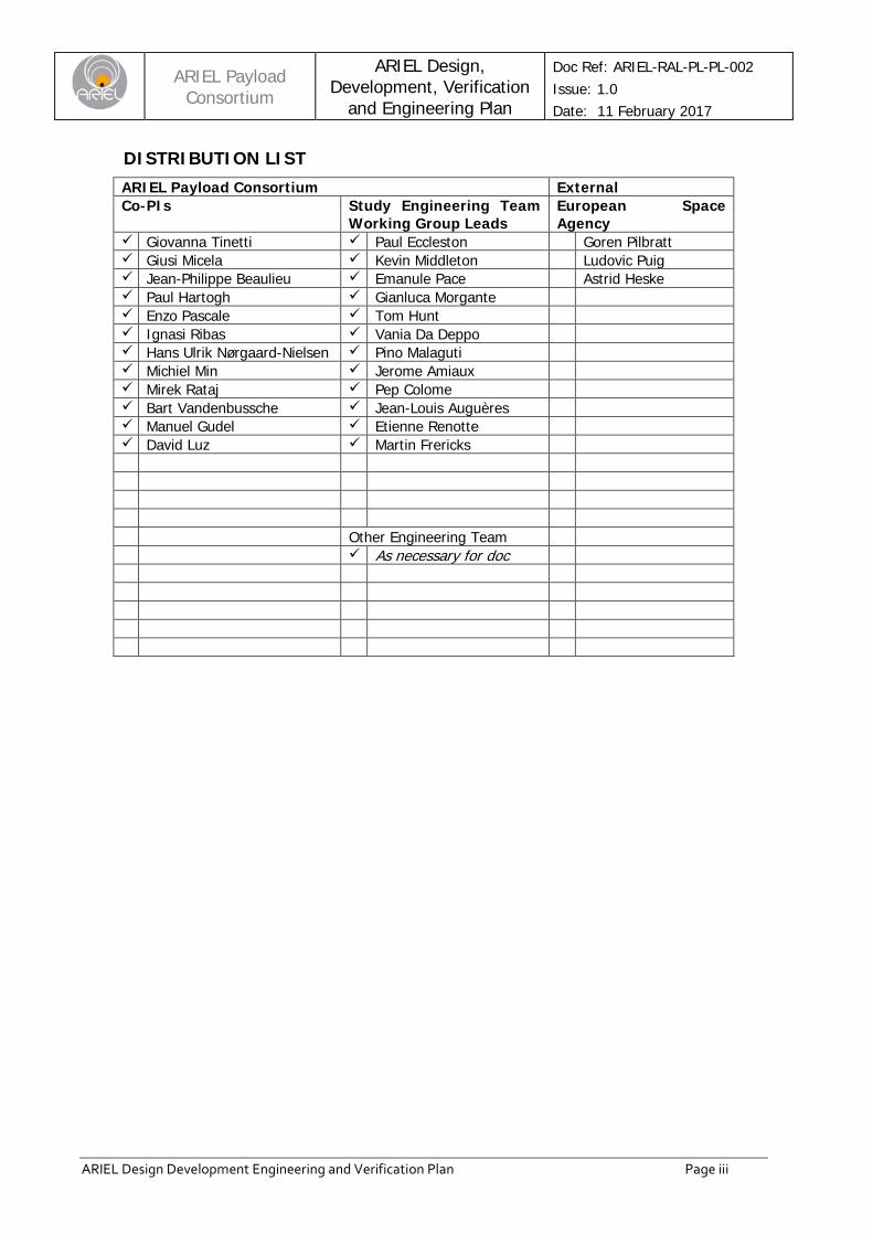
DISTRIBUTION LIST ARIEL Payload Consortium External Co-PIs Study Engineering Team
Working Group Leads European Space Agency
Giovanna Tinetti Paul Eccleston Goren Pilbratt Giusi Micela Kevin Middleton Ludovic Puig Jean-Philippe Beaulieu Emanule Pace Astrid Heske Paul Hartogh Gianluca Morgante Enzo Pascale Tom Hunt Ignasi Ribas Vania Da Deppo Hans Ulrik Nørgaard-Nielsen Pino Malaguti Michiel Min Jerome Amiaux Mirek Rataj Pep Colome Bart Vandenbussche Jean-Louis Auguères Manuel Gudel Etienne Renotte David Luz Martin Frericks Other Engineering Team As necessary for doc
ARIEL Payload
Consortium ARIEL Design,
Development, Verification and Engineering Plan
Doc Ref: ARIEL-RAL-PL-PL-002 Issue: 1.0 Date: 11 February 2017
ARIEL Design Development Engineering and Verification Plan Page iv
TABLE OF CONTENTS Document Change Details .................................................................................................. ii Distribution List .................................................................................................................. iii Table of Contents ............................................................................................................. iv
Preamble ................................................................................................................. 7
1.1 Scope ................................................................................................................................. 7
1.2 Purpose .............................................................................................................................. 7
1.3 Background to ARIEL and the ARIEL Payload ....................................................................... 7
1.4 Applicable Documents .......................................................................................................... 7
1.5 Reference Documents .......................................................................................................... 8
1.6 Terms, Definitions and Abbreviations .................................................................................... 8
Product Tree and Payload Responsibilities ................................................................. 9
Development Plan .................................................................................................. 10
3.1 Payload Qualification Approach .......................................................................................... 10
3.2 Payload Level Model Philosophy Analysis ........................................................................... 10 3.2.1 Required Deliverable Models ..................................................................................................... 10
3.2.1.1 Deliverable Structural Thermal Model (STM) ........................................................................ 10 3.2.1.2 Deliverable Avionics Model (AVM) ...................................................................................... 10 3.2.1.3 Deliverable Proto Flight Model (pFM) .................................................................................. 11 3.2.1.4 Non-Deliverable FS Components........................................................................................ 11
3.2.2 Generic Payload Level Verification Flow ..................................................................................... 11 3.2.3 Critical Items and Risk Reduction Requirements ......................................................................... 11
3.2.3.1 Active Cooler System ........................................................................................................ 11 3.2.3.2 Detector Modules .............................................................................................................. 12 3.2.3.3 Dichroic Chain .................................................................................................................. 12
3.3 Payload Test Summary ...................................................................................................... 13 3.3.1 Payload Level Test Matrix ......................................................................................................... 13 3.3.2 Detailed Payload Model Build Standards .................................................................................... 14
3.3.2.1 STM Payload Build Standard.............................................................................................. 14 3.3.2.2 AVM Payload Build Standard ............................................................................................. 15 3.3.2.3 PVM (for use at RAL) Payload Build Standard ..................................................................... 15
3.4 Subsystem Level Development Approach Overview ............................................................. 15
3.5 Ground Support Equipment Development Plans .................................................................. 15 3.5.1 Required Ground Support Equipment Requirements by Payload Model ......................................... 15 3.5.2 Mechanical Ground Support Equipment (MGSE) ......................................................................... 15 3.5.3 Optical Ground Support Equipment (OGSE) ............................................................................... 15 3.5.4 Electrical Ground Support Equipment (EGSE) ............................................................................. 16 3.5.5 Integration and Test Facilities .................................................................................................... 16
ARIEL Payload
Consortium ARIEL Design,
Development, Verification and Engineering Plan
Doc Ref: ARIEL-RAL-PL-PL-002 Issue: 1.0 Date: 11 February 2017
ARIEL Design Development Engineering and Verification Plan Page v
3.6 Payload Level AIV Planning ................................................................................................ 16
TECHNOLOGY ASSESSMENT AND NEAR-TERM DEVELOPMENT PLANS ............. 18
Spares Philosophy .................................................................................................. 19
5.1 Subsystem Level Spares .................................................................................................... 19
Engineering Planning .............................................................................................. 20
6.1 Requirements Management ................................................................................................ 20 6.1.1 Requirements Engineering Process ........................................................................................... 20
6.1.1.1 Requirement Identification, Analysis and Validation .............................................................. 20 6.1.1.2 Requirement Allocation ...................................................................................................... 22 6.1.1.3 Requirement Maintenance ................................................................................................. 22
6.2 System Analysis ................................................................................................................ 23 6.2.1 Structural Analyses ................................................................................................................... 23 6.2.2 Thermal Analyses ..................................................................................................................... 23 6.2.3 Optical Analyses ...................................................................................................................... 24 6.2.4 STOP Analysis ......................................................................................................................... 24 6.2.5 Electrical Analysis .................................................................................................................... 24 6.2.6 Systems Interaction Analyses .................................................................................................... 25
6.3 Technical Design Activities ................................................................................................. 25 6.3.1 Payload Systems Team ............................................................................................................ 25 6.3.2 Technical Resource Management .............................................................................................. 25
6.4 Flight Software Activities .................................................................................................... 27
Verification Planning ............................................................................................... 28
7.1 Verification Objectives ........................................................................................................ 28 7.1.1 Verification Process Logic ......................................................................................................... 28 7.1.2 Verification Process Flow .......................................................................................................... 28 7.1.3 Verification Approach ................................................................................................................ 28
7.1.3.1 Verification Approach Derivation ......................................................................................... 29 7.1.3.2 Verification Close-out ........................................................................................................ 29 7.1.3.3 Verification Close-out Exceptions ........................................................................................ 29
7.1.4 Verification Methods ................................................................................................................. 29
7.2 Verification Responsibilities ................................................................................................ 29 7.2.1 Verification Control Board (VCB) ................................................................................................ 29 7.2.2 Other Reviews ......................................................................................................................... 30
7.3 Verification Planning Overview ............................................................................................ 30 7.3.1 Planning for Verification by Test ................................................................................................. 30
7.3.1.1 Test Programme Definition ................................................................................................. 30 7.3.1.2 Re-Integration Tests .......................................................................................................... 30 7.3.1.3 Test Versus Verification Stages .......................................................................................... 30
ARIEL Payload
Consortium ARIEL Design,
Development, Verification and Engineering Plan
Doc Ref: ARIEL-RAL-PL-PL-002 Issue: 1.0 Date: 11 February 2017
ARIEL Design Development Engineering and Verification Plan Page vi
7.3.1.4 Test Versus Verification Levels ........................................................................................... 30 7.3.1.5 Test Matrices .................................................................................................................... 30
7.3.2 Planning for Verification by Analysis ........................................................................................... 30 7.3.2.1 Analysis Programme Definition ........................................................................................... 31 7.3.2.2 Verification Analysis Criteria ............................................................................................... 31 7.3.2.3 Similarity Criteria ............................................................................................................... 31 7.3.2.4 Analysis Versus Verification Stages and Levels ................................................................... 31
7.3.3 Planning for Verification by Review of Design .............................................................................. 31 7.3.3.1 Review-of-design Programme Definition .............................................................................. 31 7.3.3.2 Review-of-design Versus Verification Stages and Levels ...................................................... 32
7.3.4 Planning for Verification by Inspection ........................................................................................ 32 7.3.4.1 Inspection Programme Definition ........................................................................................ 32 7.3.4.2 Inspection Versus Verification Stages and Levels ................................................................. 32
Annex A: Verification and Calibration PreliMinary Planning Table ................................ 33
ARIEL Payload
Consortium ARIEL Design,
Development, Verification and Engineering Plan
Doc Ref: ARIEL-RAL-PL-PL-002 Issue: 1.0 Date: 11 February 2017
ARIEL Design Development Engineering and Verification Plan Page 7
PREAMBLE
1.1 SCOPE This plan defines the design and development approach for the ARIEL Payload during Phase B and Phase C/D activities. It is based on the currently defined requirements and constraints as given in the MRD (AD1) and PID-A (AD7). In particular, this DDEVP is informed by, and tailored from the ESA ECSS requirements.
This version of the document has been prepared for the Mission Selection Review (MSR), at the end of the phase A. Much detailed work remains to be carried out on all levels of the design and development plans at system, payload and sub-system level. We anticipate that this work will form a significant part Phase B activities and the DDEVPs for the spacecraft, payload and sub-systems will be harmonised and completed by the time of the PDR. A further review and iteration will then take place up to the CDR. After CDR it is proposed that this document would not normally be maintained and the information will be superseded by subsequent up-issues of the following documents:
• ARIEL Payload AIV Plan • ARIEL Payload Internal Receivables and Deliverables Items List (RecDels) • ARIEL Payload Product Tree • ARIEL Payload Schedule • Subsystem and unit level Design and Development Plans (as necessary)
1.2 PURPOSE This document serves as the master guide to the proposed plans for design and development of the ARIEL Payload. The required hardware model philosophy is analysed and suggested (will be definitively defined in later issues of the document) and the impacts on the required fidelity of the delivered subsystems are examined. This document also provides the framework for the design and verification methodologies to be used by the ARIEL team throughout the project lifecycle.
1.3 BACKGROUND TO ARIEL AND THE ARIEL PAYLOAD Background information of the mission and science objectives can be found in [AD1] and [AD3] and a description of the current Payload design can be found in the Design Document, [AD4].
1.4 APPLICABLE DOCUMENTS AD # APPLICABLE DOCUMENT TITLE DOCUMENT ID ISSUE / DATE 1 ARIEL MRD (Mission Requirements Document) ESA-ARIEL-EST-MIS-
RD-001 1.2 / Jan-2017
2 Deleted at Iss 0.6 – superceeded by [AD4] and [AD7]
ESA-ARIEL-EST-PL-DD-001
1.1 / Sep 2015
3 ARIEL SciRD (Science Requirements Document) ESA-ARIEL-EST-SCI-RS-001
1.3 / Feb-2017
4 ARIEL Payload Design Description Document ARIEL-RAL-PL-DD-001 2.0 / Feb 2017 5 ARIEL Payload Consortium Management Plan ARIEL-RAL-PL-PL-001 1.0 / Feb 2017 6 ARIEL Terms, Definitions and Abbreviations ARIEL-RAL-PL-LI-001 2.0 / Feb 2017 7 ARIEL Payload Interface Document Part-A PID-A ARIEL-ESA-PL-IF-001 0.14 / December
2016 8 ARIEL Payload Level Assembly Integration and
Verification Plan ARIEL-RAL-PL-PL-007 1.0 / Feb 2017
9 ARIEL Payload Product Assurance Plan ARIEL-RAL-PL-PL-006 1.0 / Feb 2017 10 ARIEL Payload Critical Technologies Status and
Plans ARIEL-RAL-PL-TN-006 1.0 / Feb 2017
ARIEL Payload
Consortium ARIEL Design,
Development, Verification and Engineering Plan
Doc Ref: ARIEL-RAL-PL-PL-002 Issue: 1.0 Date: 11 February 2017
ARIEL Design Development Engineering and Verification Plan Page 8
1.5 REFERENCE DOCUMENTS RD # REFERENCE DOCUMENT TITLE DOCUMENT ID ISSUE / DATE 1 Deleted at Iss 0.6 – duplicate of [AD7] ARIEL-RAL-PL-DD-
001 1.0
2 Minutes of Meeting: Pathfinder Telescope Mirror Program KO
ARIEL-RAL-PL-MIN-006
1.0
3
1.6 TERMS, DEFINITIONS AND ABBREVIATIONS A list of the terms, definitions and abbreviations applicable to ARIEL can be found in [AD6].
ARIEL Payload
Consortium ARIEL Design,
Development, Verification and Engineering Plan
Doc Ref: ARIEL-RAL-PL-PL-002 Issue: 1.0 Date: 11 February 2017
ARIEL Design Development Engineering and Verification Plan Page 9
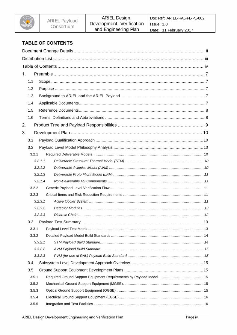
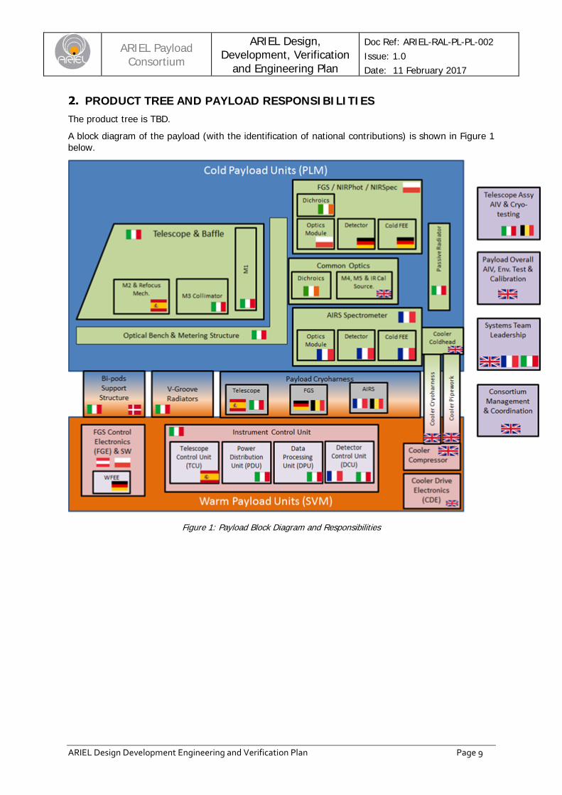
PRODUCT TREE AND PAYLOAD RESPONSIBILITIES The product tree is TBD. A block diagram of the payload (with the identification of national contributions) is shown in Figure 1 below.
Figure 1: Payload Block Diagram and Responsibilities
ARIEL Payload
Consortium ARIEL Design,
Development, Verification and Engineering Plan
Doc Ref: ARIEL-RAL-PL-PL-002 Issue: 1.0 Date: 11 February 2017
ARIEL Design Development Engineering and Verification Plan Page 10
DEVELOPMENT PLAN
3.1 PAYLOAD QUALIFICATION APPROACH The ARIEL Payload Module (PLM) will follow a proto Flight Model (pFM) approach to overall qualification. Some major design aspects will be de-risked earlier in the program using the prior models (as discussed in sections below), but it is planned that formal environmental qualification at complete payload module level only takes place on the pFM Payload Module.
The basic philosophy for the ARIEL verification programme is to test the critical interfaces, environmental requirements and functionality as early as possible during phases B/C/D to remove as much risk as possible from the proto flight model programme. This applies to all levels in the payload and system build. The development and verification of the payload will be undertaken in accordance with the requirements in the PID-A (AD7) and the guidance in the applicable ECSS standards. In order to allow early de-risking we plan to build a Performance Verification Model (PVM) of the PayLoad Module (PLM) and warm electronics units (ICU, FGE and CDE)) that will be form, fit and functionally compliant but with no compulsion that the units within it are capable of undergoing environmental testing to qualification level. This model will not be environmentally tested to qualification levels and is not proposed to be deliverable to spacecraft level. By following this programme rather than committing to a full qualification model we allow flexibility in the schedule. That is, we are not dependent on completion of all unit qualification programmes to start the interface and performance verification activities at Payload level. At subsystem level there are a variety of qualification approaches that may be followed as outlined in section 3.4. Some subsystems (i.e. the cooler) have a dedicated qualification model which will undergo a full suite of environmental testing (including lifetime testing) prior to the FM builds. Some preliminary details are contained later in this document and in the appropriate subsystem level design and development plans, to be produced at a later stage.
3.2 PAYLOAD LEVEL MODEL PHILOSOPHY ANALYSIS
3.2.1 Required Deliverable Models The following sub-sections outline our currently foreseen model philosophy, tailored to fit with our development plan, the need to de-risk major interfaces with the spacecraft as early as possible and to reduce the overall model development schedule. Here then we outline our proposed build standard and the top level purpose of each of the deliverable models to be delivered to system level.
3.2.1.1 Deliverable Structural Thermal Model (STM) The STM ARIEL Payload Module that will be delivered to S/C level AIV:
• Basic PLM structure with mass and thermal dummies – no functional requirements • The earlier breadboard model of the Telescope primary mirror may well be part of this STM. • Mechanical and thermal interfaces flight representative but not necessarily form / tolerance
compliant • Development of engineering model (EDM) coolers delivered alongside STM with EM Cooler
Drive Electronics (CDE) – this is TBC dependant on schedule matching with S/C program. • Capable of undergoing full spacecraft level environmental testing to qualification levels and has
been tested to qualification levels before delivery (TBC) • Demonstrate thermal design and provide correlation for Thermal Mathematical Model (TMM) • Used for mechanical fit check, vibration testing and thermal tests at S/C level
3.2.1.2 Deliverable Avionics Model (AVM) The AVM that the ARIEL Payload will be delivered to S/C level AIV:
• ICU (incl. DCU), FGE and TCU engineering models or simulators and EGSE to simulate Payload function.
ARIEL Payload
Consortium ARIEL Design,
Development, Verification and Engineering Plan
Doc Ref: ARIEL-RAL-PL-PL-002 Issue: 1.0 Date: 11 February 2017
ARIEL Design Development Engineering and Verification Plan Page 11
• Cooler control electronics breadboard / EM to simulate power draw and EMC to S/C level. • Pull through of Payload AIV process including test facilities and procedures • Used for Electrical interface compatibility testing at S/C level • Used at system level to check out electrical and communications interfaces and set up ground
test sequences and flight operations.
3.2.1.3 Deliverable Proto Flight Model (pFM) The pFM ARIEL Payload that will be delivered to S/C level AIV will provide for:
• pFM approach to most design aspects except as outlined elsewhere in this document • Full AIV sequence including appropriate system level performance verification and calibration
3.2.1.4 Non-Deliverable FS Components The ARIEL flight spare philosophy is subject to further discussion and alteration. The FS ARIEL Payload components that will be held at either their institute of origin or at RAL (TBC) and delivered to S/C level if required for rapid replacement either at the satellite integration facility or following return of the Payload Module to RAL
• All major units of the Payload will provide flight spare components at the appropriate level (TBD).
• Flight spare units will be tested at unit level or, where not possible on the Payload level PVM (TBD).
• Acceptance testing for most design aspects since formally qualified on pFM model.
Further details on the spare philosophy and expected Flight Spare items will eventually (in phase B) given in the Project Management Plan [AD5].
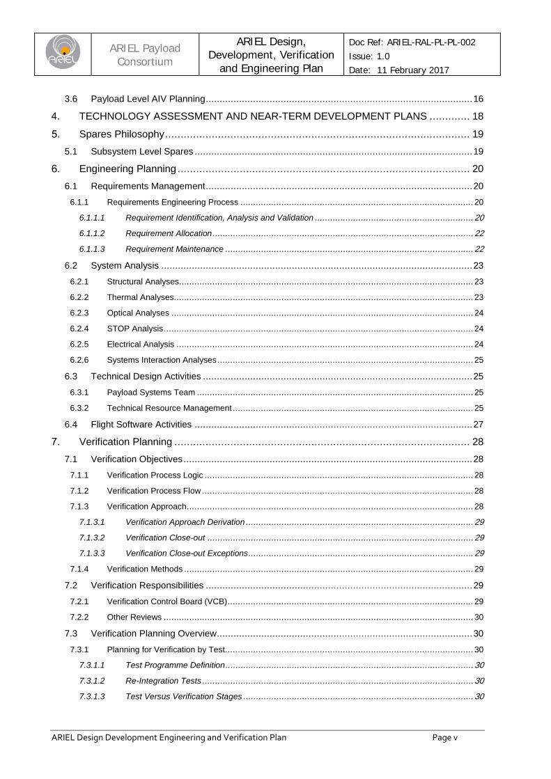
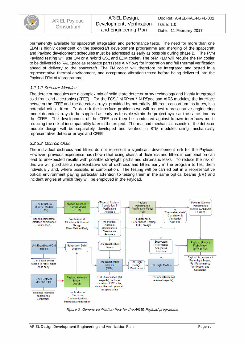
3.2.2 Generic Payload Level Verification Flow We show in Figure 2 how the various interface and environmental requirements are verified using the payload models and how the information flows within the Payload development programme. This philosophy mimics closely that undertaken for the JWST MIRI programme. In addition to undergoing testing at Payload and unit level, we also expect information on interface compliance, functionality and performance to be generated during the system level tests with the STM and AVM. This philosophy is expected to be followed for the critical sub-systems and interfaces in the Payload. In some circumstances full qualification before delivery to the PVM programme will be waived and a separate QM/pFM path may be followed. We have made an initial identification of the critical items which we discuss in the following subsections. As the design is consolidated during phase B we will review and adjust both the AIV plan and the model philosophy as required to ensure all critical items are addressed as early as possible and at the appropriate level with the Payload, instrument and sub-system level AIV programmes.
3.2.3 Critical Items and Risk Reduction Requirements In order to reduce the risk levels on some of the key aspects of the ARIEL Payload design the following activities over and above those required to simply deliver the minimum required build standard for each model have been included in the program.
3.2.3.1 Active Cooler System We highlight the active cooler system (ACS) as this is deemed as a single point failure for the Payload (and mission) requirements. The ACS will therefore follow a full qualification path. There will be at least one EDM (i.e. engineering demonstration model) to address the functional, interface and performance aspects as early as possible in the programme, a QM to undergo full qualification level performance, environmental and interface verification and a flight model. A second EDM may be built for use in the Payload PVM programme and either this or the QM will be used for lifetime testing. An EDM is denoted as deliverable for system level testing and either this model or the QM will be
ARIEL Payload
Consortium ARIEL Design,
Development, Verification and Engineering Plan
Doc Ref: ARIEL-RAL-PL-PL-002 Issue: 1.0 Date: 11 February 2017
ARIEL Design Development Engineering and Verification Plan Page 12
permanently available for spacecraft integration and performance tests. The need for more than one EDM is highly dependent on the spacecraft development programme and merging of the spacecraft and Payload development schedules must be addressed as early as possible during phase B. The PVM Payload testing will use QM or a hybrid GSE and EDM cooler. The pFM PLM will require the FM cooler to be delivered to RAL Space as separate parts (see AIV flow) for integration and full thermal verification ahead of delivery to the spacecraft. The FM cooler will therefore be integrated and tested in a representative thermal environment, and acceptance vibration tested before being delivered into the Payload PFM AIV programme.
3.2.3.2 Detector Modules The detector modules are a complex mix of solid state detector array technology and highly integrated cold front end electronics (CFEE). For the FGS / NIRPhot / NIRSpec and AIRS modules, the interface between the CFEE and the detector arrays, provided by potentially different consortium institutes, is a potential critical item. To de-risk the interface problems we will request representative engineering model detector arrays to be supplied as early as feasible within the project cycle at the same time as the CFEE. The development of the CFEE can then be conducted against known interfaces much reducing the risk of incompatibility later in the project. Thermal and mechanical aspects of the detector module design will be separately developed and verified in STM modules using mechanically representative detector arrays and CFEE.
3.2.3.3 Dichroic Chain The individual dichroics and filters do not represent a significant development risk for the Payload. However, previous experience has shown that using chains of dichroics and filters in combination can lead to unexpected results with possible straylight paths and chromatic leaks. To reduce the risk of this we will purchase a representative set of dichroics and filters early in the program to test them individually and, where possible, in combination. The testing will be carried out in a representative optical environment paying particular attention to testing them in the same optical beams (f/#) and incident angles at which they will be employed in the Payload.
Figure 2: Generic verification flow for the ARIEL Payload programme
ARIEL Payload
Consortium ARIEL Design,
Development, Verification and Engineering Plan
Doc Ref: ARIEL-RAL-PL-PL-002 Issue: 1.0 Date: 11 February 2017
ARIEL Design Development Engineering and Verification Plan Page 13
The blue boxes indicate the unit level models required, the green boxes indicate payload models proposed for delivery to system and the grey box non deliverable payload models. The red connectors show physical deliveries and the others information flow. The uncoloured boxes indicate the information generated from the model test programmes at unit, Payload and/or system level. The text below each model indicates what verification issues will be addressed.
3.3 PAYLOAD TEST SUMMARY
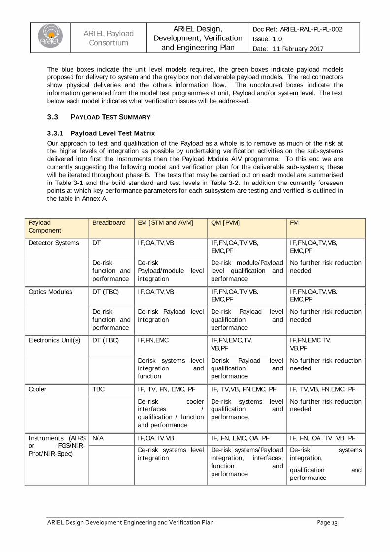
3.3.1 Payload Level Test Matrix Our approach to test and qualification of the Payload as a whole is to remove as much of the risk at the higher levels of integration as possible by undertaking verification activities on the sub-systems delivered into first the Instruments then the Payload Module AIV programme. To this end we are currently suggesting the following model and verification plan for the deliverable sub-systems; these will be iterated throughout phase B. The tests that may be carried out on each model are summarised in Table 3-1 and the build standard and test levels in Table 3-2. In addition the currently foreseen points at which key performance parameters for each subsystem are testing and verified is outlined in the table in Annex A.
Payload Component
Breadboard EM [STM and AVM] QM [PVM] FM
Detector Systems DT IF,OA,TV,VB IF,FN,OA,TV,VB, EMC,PF
IF,FN,OA,TV,VB, EMC,PF
De-risk function and performance
De-risk Payload/module level integration
De-risk module/Payload level qualification and performance
No further risk reduction needed
Optics Modules DT (TBC) IF,OA,TV,VB IF,FN,OA,TV,VB, EMC,PF
IF,FN,OA,TV,VB, EMC,PF
De-risk function and performance
De-risk Payload level integration
De-risk Payload level qualification and performance
No further risk reduction needed
Electronics Unit(s) DT (TBC) IF,FN,EMC IF,FN,EMC,TV, VB,PF
IF,FN,EMC,TV, VB,PF
Derisk systems level integration and function
Derisk Payload level qualification and performance
No further risk reduction needed
Cooler TBC IF, TV, FN, EMC, PF IF, TV,VB, FN,EMC, PF IF, TV,VB, FN,EMC, PF
De-risk cooler interfaces / qualification / function and performance
De-risk systems level qualification and performance.
No further risk reduction needed
Instruments (AIRS or FGS/NIR-Phot/NIR-Spec)
N/A IF,OA,TV,VB IF, FN, EMC, OA, PF IF, FN, OA, TV, VB, PF
De-risk systems level integration
De-risk systems/Payload integration, interfaces, function and performance
De-risk systems integration,
qualification and performance
ARIEL Payload
Consortium ARIEL Design,
Development, Verification and Engineering Plan
Doc Ref: ARIEL-RAL-PL-PL-002 Issue: 1.0 Date: 11 February 2017
ARIEL Design Development Engineering and Verification Plan Page 14
Table 3-1: Test matrix for the ARIEL components showing which tests are done on models to verify compliance and remove downstream risk
Notes: DT – Development testing; IF – Interface Verification; OA – Optical alignment; TV – Thermal vacuum / thermal balance test; VB – Vibration test; FN – Functional verification; EMC – EMI compatibility verification; PF – Performance verification
Payload Component Breadboard STM PVM pFM
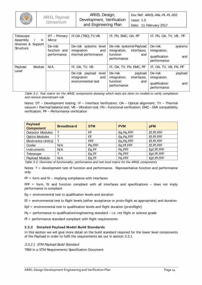
Detector Modules T FF Eq,Pq,FFF Ef,Pf,FFF Optics Modules T FF Eq,Pq,FFF Ef,Pf,FFF Electronics Unit(s) T FFF Eq,Pq,FFF Ef,Pf,FFF Cooler N/A Pq,FFF Eq,Pf,FFF Ef,Pf,FFF Instruments N/A Eq,FF Pq,FFF Epf,Pf,FFF Telescope T Eq,FF Pq,FFF Epf,Pf,FFF Payload Module N/A Eq,FF Pq,FFF Epf,Pf,FFF
Table 3-2: Overview of functionality, performance and test level matrix for the ARIEL components
Notes: T = development test of function and performance. Representative function and performance only.
FF = form and fit – implying compliance with interfaces
FFF = form, fit and function compliant with all interfaces and specifications – does not imply performance is compliant
Eq = environmental test to qualification levels and duration Ef = environmental test to flight levels (either acceptance or proto-flight as appropriate) and duration
Epf = environmental test to qualification levels and flight duration (protoflight)
Pq = performance to qualification/engineering standard – i.e. not flight or science grade Pf = performance standard compliant with flight requirements
3.3.2 Detailed Payload Model Build Standards In this section we will give more detail on the build standard required for the lower level components of the Payload in order to fulfil the requirements set out in section 3.3.1.
3.3.2.1 STM Payload Build Standard TBW in a STM Requirements Specification Document.
Telescope Assembly / V-Grooves & Support Structure
DT – Primary Mirror
IF,OA (TBC),TV,VB IF, FN, EMC, OA, PF IF, FN, OA, TV, VB , PF
De-risk function and performance
De-risk systems level integration and thermal performance
De-risk systems/Payload integration, interfaces, function and performance
De-risk systems integration,
qualification and performance
Payload Module Level
N/A IF, OA, TV, VB IF, OA, TV, FN, EMC, PF IF, OA, TV, VB, FN, PF
De-risk payload level integration and environmental test
De-risk payload integration, interfaces, function and performance
De-risk payload integration,
qualification and performance

ARIEL Payload
Consortium ARIEL Design,
Development, Verification and Engineering Plan
Doc Ref: ARIEL-RAL-PL-PL-002 Issue: 1.0 Date: 11 February 2017
ARIEL Design Development Engineering and Verification Plan Page 15
3.3.2.2 AVM Payload Build Standard TBW in a AVM Specifications Requirements Document.
3.3.2.3 PVM (for use at RAL) Payload Build Standard TBW in a PVM Requirements Specification Document.
3.4 SUBSYSTEM LEVEL DEVELOPMENT APPROACH OVERVIEW TBW following further iteration within consortium during phase B. It is expected that most of the optical units will follow a parallel development plan to the main PLM. Other units such as the electronics units, mechanisms, cooler etc will have somewhat different approached tailored to the specific requirements on what aspects of the design needs to be qualified and where early risk reduction is desirable.
3.5 GROUND SUPPORT EQUIPMENT DEVELOPMENT PLANS
3.5.1 Required Ground Support Equipment Requirements by Payload Model The details of the required ground support equipment will be given in the ARIEL Payload AIV Plan. Some definition of the possibly required GSE is given in the sections below. Note that this GSE is all intended for use at ARIEL payload level, some subsystem level GSE will also be designed and supplied with the subsystems – this will be described in the individual subsystem design and development plans.
3.5.2 Mechanical Ground Support Equipment (MGSE) An analysis of the required MGSE will be conducted as part of the Phase B activities. A full list of the required MGSE will be given in the table below in future versions of this document.
Identifier Description Quantity Used on
STM PVM pFM
MGSE1 PLM Transport Container 1
Etc….. Table 3-3: MGSE Required by Model (TBW)
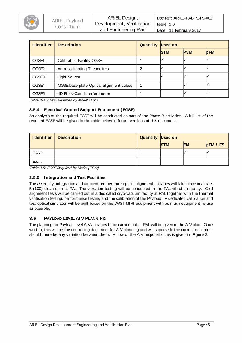
3.5.3 Optical Ground Support Equipment (OGSE) An initial list of the required OGSE is given in the table below where the usage on the individual models is shown. A full analysis and design of the dedicated equipment will be carried out as part of the Phase B activities.
ARIEL Payload
Consortium ARIEL Design,
Development, Verification and Engineering Plan
Doc Ref: ARIEL-RAL-PL-PL-002 Issue: 1.0 Date: 11 February 2017
ARIEL Design Development Engineering and Verification Plan Page 16
Identifier Description Quantity Used on
STM PVM pFM
OGSE1 Calibration Facility OGSE 1
OGSE2 Auto-collimating Theodolites 2
OGSE3 Light Source 1
OGSE4 MGSE base plate Optical alignment cubes 1
OGSE5 4D PhaseCam Interferometer 1 Table 3-4: OGSE Required by Model (TBC)
3.5.4 Electrical Ground Support Equipment (EGSE) An analysis of the required EGSE will be conducted as part of the Phase B activities. A full list of the required EGSE will be given in the table below in future versions of this document.
Identifier Description Quantity Used on
STM EM pFM / FS
EGSE1 1
Etc….. Table 3-5: EGSE Required by Model (TBW)
3.5.5 Integration and Test Facilities The assembly, integration and ambient temperature optical alignment activities will take place in a class 5 (100) cleanroom at RAL. The vibration testing will be conducted in the RAL vibration facility. Cold alignment tests will be carried out in a dedicated cryo-vacuum facility at RAL together with the thermal verification testing, performance testing and the calibration of the Payload. A dedicated calibration and test optical simulator will be built based on the JWST-MIRI equipment with as much equipment re-use as possible.
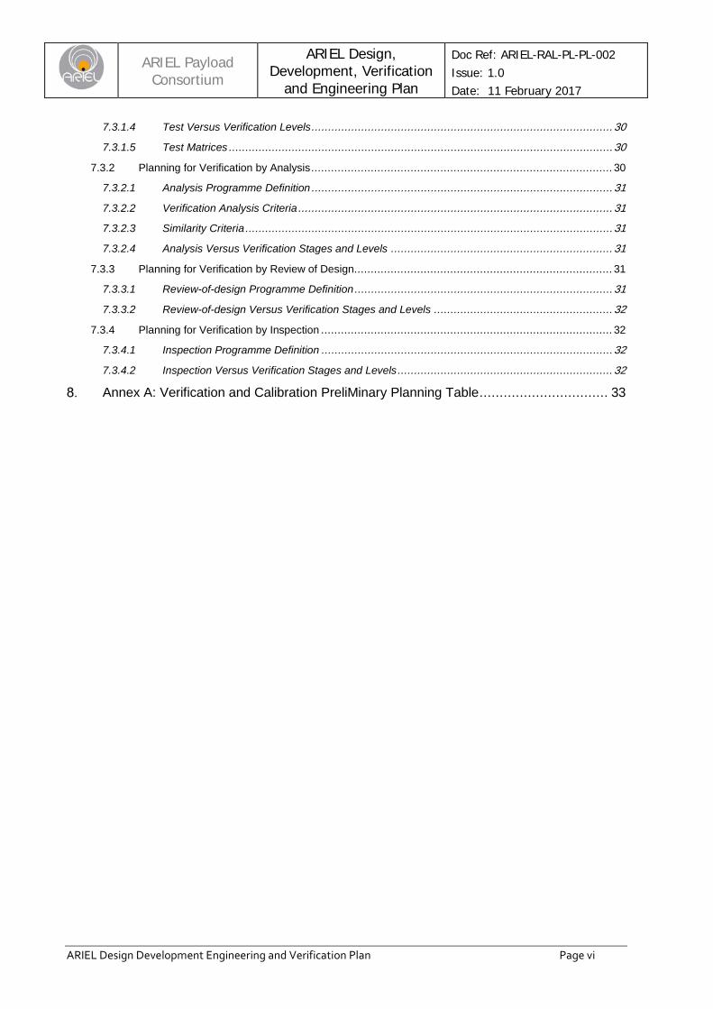
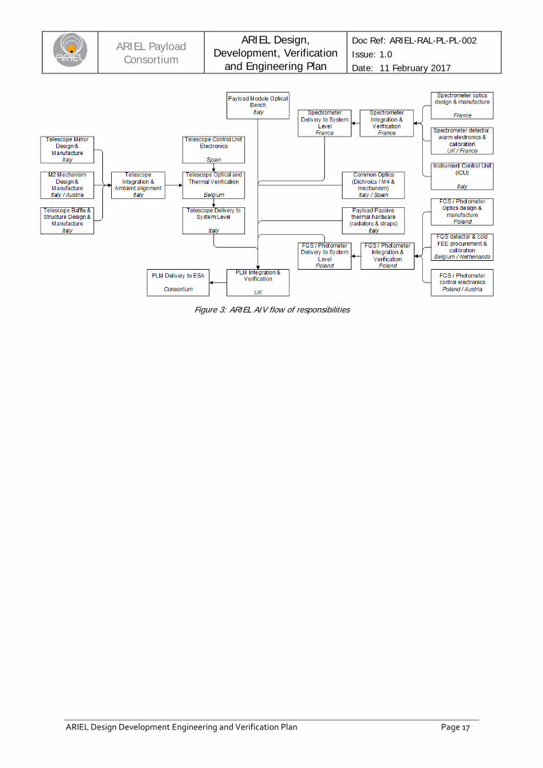
3.6 PAYLOAD LEVEL AIV PLANNING The planning for Payload level AIV activities to be carried out at RAL will be given in the AIV plan. Once written, this will be the controlling document for AIV planning and will supersede the current document should there be any variation between them. A flow of the AIV responsibilities is given in Figure 3.
ARIEL Payload
Consortium ARIEL Design,
Development, Verification and Engineering Plan
Doc Ref: ARIEL-RAL-PL-PL-002 Issue: 1.0 Date: 11 February 2017
ARIEL Design Development Engineering and Verification Plan Page 17
Figure 3: ARIEL AIV flow of responsibilities
ARIEL Payload
Consortium ARIEL Design,
Development, Verification and Engineering Plan
Doc Ref: ARIEL-RAL-PL-PL-002 Issue: 1.0 Date: 11 February 2017
ARIEL Design Development Engineering and Verification Plan Page 18
TECHNOLOGY ASSESSMENT AND NEAR-TERM DEVELOPMENT PLANS An assessment of TRLs and near term development plans are given in the Critical Technologies Status and Plans document [AD10].
ARIEL Payload
Consortium ARIEL Design,
Development, Verification and Engineering Plan
Doc Ref: ARIEL-RAL-PL-PL-002 Issue: 1.0 Date: 11 February 2017
ARIEL Design Development Engineering and Verification Plan Page 19
SPARES PHILOSOPHY
5.1 SUBSYSTEM LEVEL SPARES Details of the plan for spares appear [AD5].
ARIEL Payload
Consortium ARIEL Design,
Development, Verification and Engineering Plan
Doc Ref: ARIEL-RAL-PL-PL-002 Issue: 1.0 Date: 11 February 2017
ARIEL Design Development Engineering and Verification Plan Page 20
ENGINEERING PLANNING
6.1 REQUIREMENTS MANAGEMENT The objectives of requirements engineering are to ensure that the:
• Science / high level requirements for ARIEL are properly interpreted and subsequently devolved into a coherent and complete set of Payload system and lower assembly level specifications.
• Requirement status and traceability are controlled on a day-to-day basis. • Requirements are verified correctly to ensure validation and acceptance of the Payload.
6.1.1 Requirements Engineering Process The requirements engineering process basically consists of the following sub-processes:
6.1.1.1 Requirement Identification, Analysis and Validation The explicit high-level requirements for ARIEL will be reviewed, in conjunction with the Payload Science Team, to reach a thorough understanding of their underlying expectations and objectives. In addition, the review aims to identify apparently incomplete, ambiguous or contradictory requirements and to highlight these to the appropriate higher levels for clarification / resolution. Any analyses performed in earlier project phases will be re-examined for their validity.
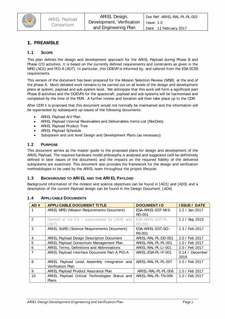
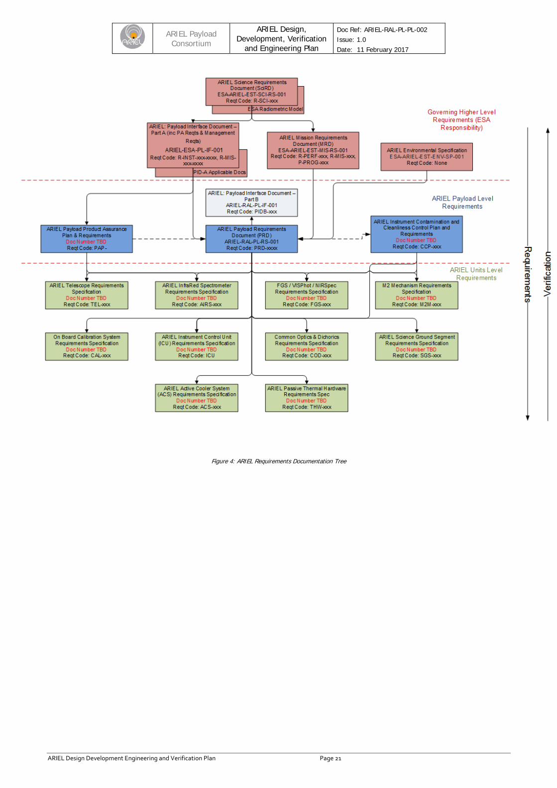
Initial discussions may reveal conflicts between requirements and constraints. In such cases, studies will be performed at Payload system level in order to trade-off the conflicting elements. The studies will provide recommendations for modifying the conflicting requirements together with an assessment of the impact of such a modification. The requirements shall be generated and allocated top-down at the different levels within the ARIEL project in order to form a tree of Payload and sub-system level requirements documents containing consistent performance, design, interface, environmental, operational and support requirements. This documentation hierarchy is shown in Figure 4below.
ARIEL Payload
Consortium ARIEL Design,
Development, Verification and Engineering Plan
Doc Ref: ARIEL-RAL-PL-PL-002 Issue: 1.0 Date: 11 February 2017
ARIEL Design Development Engineering and Verification Plan Page 21
Figure 4: ARIEL Requirements Documentation Tree
ARIEL Payload
Consortium ARIEL Design,
Development, Verification and Engineering Plan
Doc Ref: ARIEL-RAL-PL-PL-002 Issue: 1.0 Date: 11 February 2017
ARIEL Design Development Engineering and Verification Plan Page 22
The identified “baseline” requirements will be documented using the DOORS requirement management tool previously used by RAL Space for similar space instrumentation projects. This will enable effective tracking of requirements flow-down, management of changes and later be used to record and track the verification activities. Note that it is the intention to impose the use of this specific format for verification tracking and report at all levels within the project in order to facilitate the efficient completion of the final verification matrix for the Payload.
Once the requirements baseline has been produced (at the Payload SRR), a validation process is performed in parallel with the functional analysis. In addition, issues may emerge leading to functional or design conflicts (e.g. mutually incompatible requirements). Such instances will require re-examination of the higher-level requirements leading to a change in the requirement baseline.
6.1.1.2 Requirement Allocation The Payload system requirements will be flowed down to lower level system elements and based on functional and architectural analyses - taking full consideration of the need to be able to verify requirements at the level at which they are applicable. To this end each requirement shall be:
• Traceable; • Unique and associated to a proper identifier (for instance a document and sub clause number); • Single and not a combination of several requirements; • Verifiable using one or more approved verification methods; • Unambiguous; • Referenced as necessary to other requirements (with applicable document and sub clause
identification) and should be associated with a specific title.
Successful verification starts with a satisfactory set of project requirements. Each requirement shall be seen as both the origin and the conclusion of the verification process, and shall be treated as fundamental technical information rather than a constituent of a verbose text. The requirement flow-down is repeated to define successively lower level functional and performance requirements, thus defining architectures at increasing levels of detail. System requirements are allocated and defined in sufficient detail to provide design and verification criteria to support the integrated Payload system design.
The requirement criticality, in terms of technical and programmatic impacts on the verification implementation, shall be assessed by early involvement of the verification team in the requirement definition process since it drives the verification strategy.
Some requirements do not require to be tracked if in practice they are: • Obvious in their execution (example: requirements for test procedure/report); • Redundant with other requirements; • Purely descriptive (example: definitions). • These requirements shall be identified and marked with a proper non-tracking decision.
However, in the case that requirements from the higher levels (i.e. EID-A) do not meet these requirements they will still be flown down to the ARIEL PRD or EID-B and to lower levels where applicable in order that the verification evidence for these requirements is still documented.
6.1.1.3 Requirement Maintenance Requirements at all levels will be maintained throughout the ARIEL project lifecycle.
The allocation of system performance requirements to sub-functions is documented (within the appropriate requirements management tool) in order to provide requirement traceability and facilitate later changes.
ARIEL Payload
Consortium ARIEL Design,
Development, Verification and Engineering Plan
Doc Ref: ARIEL-RAL-PL-PL-002 Issue: 1.0 Date: 11 February 2017
ARIEL Design Development Engineering and Verification Plan Page 23
Any potential changes to the requirements will be analysed for their impact throughout the system before being included in the new baseline. Any change to the requirements will be fully documented in order to guarantee full visibility and traceability of the baseline.
Documentation responsibility (also termed “book captaincy”) for the subsystem requirements and interface documentation are described in section 6.3.
6.2 SYSTEM ANALYSIS
6.2.1 Structural Analyses Structural analysis as is expected to be required by the EID-A and the relevant ECSS documents will be conducted. This will include (but not necessarily be limited to):
• Static Analyses: o Quasi-static load analysis based on the supplied interface forces. Evaluation of material
stresses and bolt loads. o Thermo-elastic analysis. Evaluation of material stresses induced by CTE, material
margins of safety under thermal induced loading, deformations of optical surfaces and displacements between them to feed into optical analysis (see STOP analysis below).
o 1g Gravity Sag analysis. Evaluation of the deflections and changes in optical alignment under 1g in configurations used in AIV at Payload and spacecraft levels, comparison with the expected 0g alignment.
o Spacecraft Interface tolerance analysis. Evaluation of interface loads and material stress levels for defined offsets of the spacecraft interface points. Confirmation that the unit can withstand the interface loads with a bolt missing at each interface position.
• Dynamic Analyses: o Modal analysis at both Payload and sub-system level. Initial verification that the
minimum frequency requirements are met. Provides input to test planning and predictions for vibration tests and acts as correlation criteria of dynamic model.
o Random Vibration Analysis. Evaluation of material stresses induced under random vibration loads.
o Micro-vibration analysis. This will be conducted in phase C/D if deemed to be necessary to examine the effect of the micro-vibration environment of the spacecraft on the optical performance of the Payload.
6.2.2 Thermal Analyses Thermal analysis as is expected to be required by the EID-A and the relevant ECSS documents will be conducted. This will include (but not necessarily be limited to):
• Steady state analysis:
o Detailed TMM/GMM of PLM, telescope assembly and instrument box to verify systems behaviour and thermo-mechanical design at equilibrium with respect to external and internal interfaces and loads. Results will provide input for thermo-elastic analysis
o Evaluation of system(s) behaviour at worst, nominal and best thermal cases: units temperature and loads at internal and external interfaces.
o TMM/GMM sensitivity analysis and margins evaluation
o PLM reduced model to verify system behaviour with respect to external interfaces and for integration in the general S/C thermal model for sub-systems evaluation at system level. This model will be correlated with the detailed ESATAN TMM/GMM results
• Transient analysis
o PLM thermal behaviour during routine operations, cooldown and warm-up (mainly for ground testing) phases, LEOP (possible Sun intrusion evaluation), contingency

ARIEL Payload
Consortium ARIEL Design,
Development, Verification and Engineering Plan
Doc Ref: ARIEL-RAL-PL-PL-002 Issue: 1.0 Date: 11 February 2017
ARIEL Design Development Engineering and Verification Plan Page 24
operations (safe-mode, moon eclipses, failures), mission evolution (aging and degradation effects)
o Telescope mirrors dynamical behaviour during routine operations and thermal control simulations with respect to expected PLM instabilities
o Detectors dynamical behaviour during routine operations and thermal control simulations with respect to expected internal (load variations, cooler oscillations) and external (attitude, flight dynamics) instabilities
6.2.3 Optical Analyses Optical analysis as is expected to be required by the EID-A and the relevant ECSS documents will be conducted. This will include (but not necessarily be limited to):
• Optical Design o Full sequential model o Optical system layout, component specification and positioning o Aperture dimensions and positioning and ‘keep clear’ zones for the Payload structure. o Image quality analysis (geometrical spot sizes, resolution, wavelength coverage) o Throughput analysis including grating efficiencies. o Image quality degradation due to tolerances and alignment. o Analysis of the optical system due to thermal & mechanical distortions of the system.
• Straylight o Full non-sequential model o Detailed modelling of all diffraction and scattering effects of the grating (including the
unwanted orders). o Analysis of the out-of-band signal within the Payload (i.e. wavelengths outside of the
wanted bands). o Analysis of the out-of-field signal entering the Payload (i.e. everything entering the
Payload but not passing through the slit) o Design & analysis of the thermo-optical control surfaces o PSF degradation due to in-field scattering at all optical surfaces. o Analysis of particulate contamination as an input to the contamination control plan.
6.2.4 STOP Analysis TBW
6.2.5 Electrical Analysis Thermal analysis as is expected to be required by the EID-A and the relevant ECSS documents will be conducted. This will include (but not necessarily be limited to):
• Reliability Assessment report. This will initially be based on a parts count methodology, with more detailed analysis to take place in phase C/D.
• Parts stress / derating analysis (PSA). This will ensure that the selected parts will function correctly in the expected environment and will feed into the reliability analysis above. The initial sub-systems PSA will be completed by the SRR.
• Worst-case analysis (WCA). For the SRR the circuits to be analysed will be identified. Subsequent design iterations will conduct the analysis.
• Radiation analysis. A sector based approach will be used to predict the radiation exposure for critical components within the sub-systems (and Payload if applicable) based on the input predictions supplied by ESA.
• Failure Modes and Effects Analysis (FMEA). This will identify the credible failures within the Payload system and provide detail of the effects of each failure – this will then act as input to the FDIR planning.
ARIEL Payload
Consortium ARIEL Design,
Development, Verification and Engineering Plan
Doc Ref: ARIEL-RAL-PL-PL-002 Issue: 1.0 Date: 11 February 2017
ARIEL Design Development Engineering and Verification Plan Page 25
6.2.6 Systems Interaction Analyses Various analyses of how the integrated Payload hardware and software works as a system will be undertaken as is expected to be required by the EID-A and the relevant ECSS documents. These will include (but not necessarily be limited to):
• Failure Detection Isolation and Recovery (FDIR) analysis. In order to provide input to the software design and operations planning the criteria for detecting failures in the Payload system will be identified and the appropriate actions documented.
• Hardware – Software Interaction Analysis (HSIA). Analysis will be conducted to ensure that the software reacts in an acceptable way to any identified plausible hardware failures.
6.3 TECHNICAL DESIGN ACTIVITIES
6.3.1 Payload Systems Team Coordination of the technical design activities at both payload and subsystem level will be undertaken by the multi-disciplinary systems design team at RAL. Lead by the ARIEL Payload Manager, this group will carry out the following functions:
• Serve as technical interface to the customer (ESA) and Mission S/C Prime • Analyse the high level requirements and form into an ARIEL Payload Requirements Document
(PRD). • Translate the higher level requirements to subsystem levels and manage the interface with the
subcontractors and consortium partners in delivering the subsystems against these requirements.
• Coordinate the engineering activities at Payload level, where necessary tensioning the competing design priorities to produce a system optimised design solution.
• Conduct the synthesis of the design analyses at subsystem levels to build up the Payload level picture to ensure full functionality and compliance with the Payload requirements.
The systems team will include the systems engineers and the lead engineers for all disciplines (mechanical, thermal, optical, electrical / electronics, software, AIV lead, calibration).
6.3.2 Technical Resource Management Design and performance budgets reflecting the as-designed status will be generated and maintained at the various subassembly levels. The overall system design and performance budgets will be allocated to subassembly, re-assembled and managed by the Payload Systems Team.
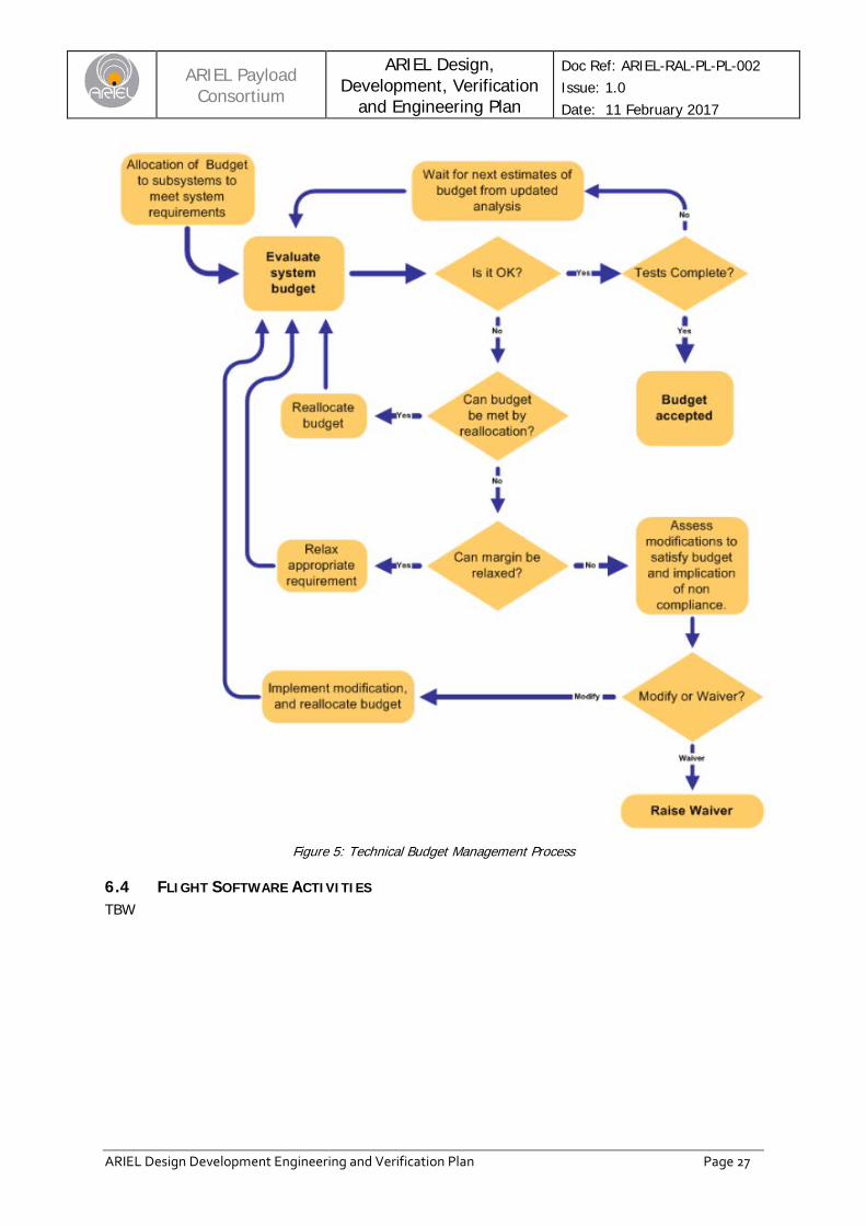
Resources management and reporting will be performed at all levels to enable the status of the resources to be sufficiently visible for analyses to be performed. These will be consolidated at Payload level to allow presentation of single consolidated Budgets Report to ESA. Thus the status and trends, versus the specified data can be found using the most up to date values and corrective action can be initiated quickly should any data be identified as unacceptable. Instituting and maintaining resource control through various stages of a project requires a common philosophy to be applied to all budgetary aspects. The resource management approach is summarised in Figure 5. The overall ARIEL resources will be devolved into subassembly and unit allocations and budgets will be specified for all resources, at all levels, with realistic contingencies to avoid unnecessary redesign or excessive over-design. The open declaration / consolidation of the contingencies held at all level avoids double accounting and also provides key risk indicators for the project. All allocations to subsystem level will be done with margin excluded – this will be made clear in the requirements. Margin will be held at system level and allocated only when necessary to the lower levels, and only when a sufficient level of maturity is deemed to have been reached. The subsystem design shall hold a level of contingency as defined by the maturity of their design.
ARIEL Payload
Consortium ARIEL Design,
Development, Verification and Engineering Plan
Doc Ref: ARIEL-RAL-PL-PL-002 Issue: 1.0 Date: 11 February 2017
ARIEL Design Development Engineering and Verification Plan Page 26
The contingencies added will reduce as the design matures and the uncertainties in budget predictions reduce. Different contingencies will typically be added at the following stages of design:
• Concept stage • Flight design level drawing/modelling stage • Measurement of an element similar to the flight design • Measurement of the actual flight element
The expected resource values will be reported regularly with increasing accuracy depending on the increasing design maturity and level of detail. Later on they will be replaced by initial measurements, then qualification results and finally acceptance values as appropriate.
Throughout the programme checks will be made continually at all levels (Payload system, subassembly and unit) for the compatibility of all deliverables with their relevant budgets. If, at any stage, a budget is found not to be satisfactory attempts will be made to either reallocate the budget or relax the margin. If neither of these is possible assessments will be made to define what modifications can be made (if any) to become compliant or else what would be the impact of being non-compliant. Depending on these assessments a decision will be made as to whether to make a modification or to raise a waiver. In all cases of a budget not being met, requirement changes at one or more levels will be necessary.
ARIEL Payload
Consortium ARIEL Design,
Development, Verification and Engineering Plan
Doc Ref: ARIEL-RAL-PL-PL-002 Issue: 1.0 Date: 11 February 2017
ARIEL Design Development Engineering and Verification Plan Page 27
Figure 5: Technical Budget Management Process
6.4 FLIGHT SOFTWARE ACTIVITIES TBW
ARIEL Payload
Consortium ARIEL Design,
Development, Verification and Engineering Plan
Doc Ref: ARIEL-RAL-PL-PL-002 Issue: 1.0 Date: 11 February 2017
ARIEL Design Development Engineering and Verification Plan Page 28
VERIFICATION PLANNING This section presents the process by which the verification activities will be performed after the Phase B kick off. During Phase B the following key activities shall be performed:
i) Generate the verification philosophy (this document). ii) Perform requirements assessment and define verification methods based on the
preliminary definition of the ARIEL PRD requirements. Note that a preliminary version of this for the key performance parameters for each subsystem is contained in the matrix in Annex A.
iii) Define requirement categories and verification strategies. iv) Refine and maintain the model philosophy, the hardware matrix and the qualification
status. v) Finalise definition of the ARIEL PRD and lower level requirements. vi) Translate and trace high-level requirements into lower level specifications. vii) Define ARIEL PRD Verification Matrices. viii) Prepare the PRD Verification Control Document (VCD).
This section describes the basic verification concepts and definitions on which the ARIEL verification approach is based. The verification process is that part of the task which demonstrates conformance to applicable requirements. A satisfactory completion of the verification process is the basis for an acceptance of the product by ESA.
7.1 VERIFICATION OBJECTIVES The aim of the ARIEL AIV programme is:
• To deliver to the project a qualified ARIEL Payload design. • To ensure that the product is in agreement with the qualified design, is free from
workmanship defects and acceptable for use. • To verify that the ARIEL Payload (including tools, procedures and resources) will be able
to fulfil mission requirements.
7.1.1 Verification Process Logic The ARIEL verification process activities shall be incrementally performed at different levels and in different stages, applying a coherent bottom-up building-block concept and utilising a suitable combination of different verification methods.
7.1.2 Verification Process Flow The ARIEL verification process flow shall be basically subdivided in the following steps:
i) Identification and classification of all the requirements to be verified; ii) Selection of verification criteria (e.g. methods/levels/stages) and models against identified
requirements; i) Establishing the planning for the associated verification activities; ii) Obtaining customer concurrence; iii) Identification of verification documentation; iv) Performance of verification tasks and verification control; v) Completion of verification control and evidence of verification close-out; vi) Customer review and final approval
7.1.3 Verification Approach To reach the verification objectives an ARIEL verification approach shall be defined in Phase B by analysing the requirements to be verified, taking into account:
• Design peculiarities;
ARIEL Payload
Consortium ARIEL Design,
Development, Verification and Engineering Plan
Doc Ref: ARIEL-RAL-PL-PL-002 Issue: 1.0 Date: 11 February 2017
ARIEL Design Development Engineering and Verification Plan Page 29
• Qualification status of candidate solution; • Availability and maturity of verification tools; • Verification and test methodologies; • Programmatic constraints; • Cost and schedule.
7.1.3.1 Verification Approach Derivation The basic ARIEL verification approach shall be derived through an iteration process, based on technical/cost/schedule considerations, which defines the "what", "how", "where" and "when" of verification by:
• Identifying a consistent set of verifiable ARIEL PRD requirements which can be subjected to the verification process;
• Selecting methods of verification; • Selecting levels of verification and the associated model philosophy; • Selecting facilities; • Identifying resources required; • Identifying the stages and the events in which the verification is implemented.
7.1.3.2 Verification Close-out The ARIEL verification process shall be considered completed when the customer (ESA) and the ARIEL team mutually agree that, on the basis of proper documented evidence, the identified requirements have been verified and the associated verification objectives fully reached.
7.1.3.3 Verification Close-out Exceptions The requirements not fully verified at a certain level shall be identified and resolved with ESA.
7.1.4 Verification Methods ARIEL verification shall be accomplished by one or more of the following verification methods which are consistent with the relevant ECSS guidelines:
• Test (T) • Analysis (A) • Review-of-design (R) • Inspection (I)
7.2 VERIFICATION RESPONSIBILITIES The ARIEL team will assign clear responsibility for the implementation of the Verification Programme. This responsibility rests with the payload AIV lead who will be assisted by the rest of the Payload Systems Team as required. The verification personnel will be involved from the early project phases in order to follow a concurrent engineering approach which avoids separation between verification requirement definition and verification implementation.
7.2.1 Verification Control Board (VCB) A VCB shall be established with the participation of customer and supplier. The objective of the VCB is to assess and approve the status of the verification process including the approval of the verification closeout through the VCD. Verification status should be carried out periodically during the execution of the project implementation and on the occasions of the important reviews.
ARIEL Payload
Consortium ARIEL Design,
Development, Verification and Engineering Plan
Doc Ref: ARIEL-RAL-PL-PL-002 Issue: 1.0 Date: 11 February 2017
ARIEL Design Development Engineering and Verification Plan Page 30
7.2.2 Other Reviews Other reviews such as TRRs, PTRs, MIPs, KIPs, NRBs etc. will be held in accordance with the ARIEL PA Plan (AD9).
Verification Responsibilities Documentation
Verification responsibilities shall be documented by RAL and approved by ESA. No verification process activity should start before the approval of the governing document.
7.3 VERIFICATION PLANNING OVERVIEW
7.3.1 Planning for Verification by Test An ARIEL test programme shall be defined in line with the selected verification approach and model philosophy, on the basis of the verification strategies for the different requirement categories. The ARIEL AIV Plan (AD8) currently outlines the major steps in the payload level AIV programme at the intended build and test facility.
7.3.1.1 Test Programme Definition In defining the test programme the following rules shall be taken into account:
• Critical items and interfaces shall be tested early in the programme; • Allowance shall be made for the possibility of alternate paths (work around plans,
contingencies); • The test flow shall minimise the incidence of the regression testing; • The reuse of models, simulators and support equipment shall be maximized; • Test feasibility shall be confirmed early in the programme.
7.3.1.2 Re-Integration Tests In response to the requirements of fault finding an equipment may have to be disassembled (de-integrated). This may also be necessary to carry out modifications or repairs. In this case disassembly and re-integration shall be performed in a controlled manner and shall be properly documented. All interfaces that were broken by de-integration shall be re-verified and all relevant integration tests shall be repeated.
These tests are also called regression tests.
7.3.1.3 Test Versus Verification Stages The overall test programme shall cover development, qualification, acceptance, pre-launch, in-orbit; and shall comply with the Standard Test Requirements defined in ECSS – Space Engineering – Testing.
7.3.1.4 Test Versus Verification Levels The overall test programme shall cover the different verification levels as necessary and shall comply with the requirements of the relevant ECSS guidelines.
7.3.1.5 Test Matrices Starting from the applicable ARIEL IRD, VCD test matrices should be established to show the correlation of requirements categories with the test to be performed at the different levels in the various verification stages. The test matrices identify the test verification events to be used for planning purposes.
7.3.2 Planning for Verification by Analysis An ARIEL analysis programme compatible with the selected verification approach will be defined on the basis of the verification strategies for the various requirement categories.
ARIEL Payload
Consortium ARIEL Design,
Development, Verification and Engineering Plan
Doc Ref: ARIEL-RAL-PL-PL-002 Issue: 1.0 Date: 11 February 2017
ARIEL Design Development Engineering and Verification Plan Page 31
7.3.2.1 Analysis Programme Definition In defining the Analysis programme, the following factors shall be taken into account:
i. The analytical technique shall be validated (verification by analysis is dependent on the quality of the analytical techniques and on the experience gained in using them);
ii. Analysis may be used in support of test or vice versa; iii. When analysis is supported by test data, testing shall be performed on a representative
model; iv. Analysis for verification may be based on design analysis.
7.3.2.2 Verification Analysis Criteria In performing the verification analyses, the following criteria shall be applied:
• The modelling system used shall be described, and its usage justified. • The product configuration to which the analysis is applied shall be identified. • All boundary conditions shall be stated. • All assumptions used in the analysis shall be stated. • The field of investigation and the range of validity of the results shall be defined. • The analytical uncertainty shall be taken into account such that specified performance is
demonstrated with an adequate margin. • Analysis shall cover both the nominal and the worst case conditions.
7.3.2.3 Similarity Criteria For an article “A” to be considered as "verified by similarity" to an article “B” the following criteria shall be satisfied:
• Article “A” is a minor variation of article “B” (i.e. by substitution of parts and materials with equivalent reliability items).
• Articles “A” and “B” perform equivalent functions (with “B” qualified for an equivalent or longer operating life with variations only in terms of performance such as accuracy, sensitivity or input-output characteristics).
• Articles “A” and “B” are produced by the same manufacturer using identical tools and manufacturing processes (in case specific technology or knowledge are required).
• The environments encountered by article “B” during its verification life cycle are equal to or more severe than the verification environments intended for article “A”.
• Article “B” was not qualified by similarity.
7.3.2.4 Analysis Versus Verification Stages and Levels Verification by analysis should be used in the qualification stage only.
Verification by analysis may be used at all verification levels.
7.3.3 Planning for Verification by Review of Design A PLM review-of-design programme compatible with the selected verification approach shall be
defined on the basis of the verification strategies for the different requirements categories.
7.3.3.1 Review-of-design Programme Definition In defining the Review-of-design programme, the following factors shall be taken into account:
i. The activity shall consist of reviewing a document or drawing for conformance to a specific requirement.
ii. The activity should be carried out simultaneously to the product design reviews. iii. The activity may include the review of lower level records (e.g. requirement verified by test
at lower level).
ARIEL Payload
Consortium ARIEL Design,
Development, Verification and Engineering Plan
Doc Ref: ARIEL-RAL-PL-PL-002 Issue: 1.0 Date: 11 February 2017
ARIEL Design Development Engineering and Verification Plan Page 32
7.3.3.2 Review-of-design Versus Verification Stages and Levels Verification by Review-of-design should be used in the qualification stage only. Verification by Review of design can be used at all verification levels.
7.3.4 Planning for Verification by Inspection An Inspection programme compatible with the selected verification approach and model philosophy shall be defined on the basis of the verification strategies for the different requirement categories.
7.3.4.1 Inspection Programme Definition In defining the Inspection programme the following factors shall be taken into account:
i. The activity shall consist of inspecting hardware and software for conformance to applicable documentation.
ii. Inspection could be complementary to Review-of-design. iii. The activity should be carried out together with quality assurance tasks during
manufacturing or integration process.
7.3.4.2 Inspection Versus Verification Stages and Levels Verification by Inspection may be used in all stages.
Verification by Inspection may be used at all verification levels.
ARIEL Payload
Consortium ARIEL Design,
Development, Verification and Engineering Plan
Doc Ref: ARIEL-RAL-PL-PL-002 Issue: 1.0 Date: 11 February 2017
ARIEL Design Development Engineering and Verification Plan Page 33
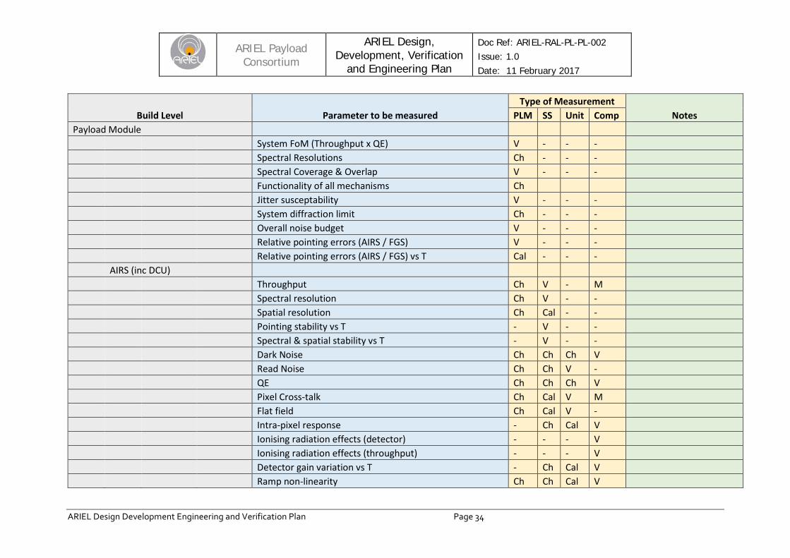
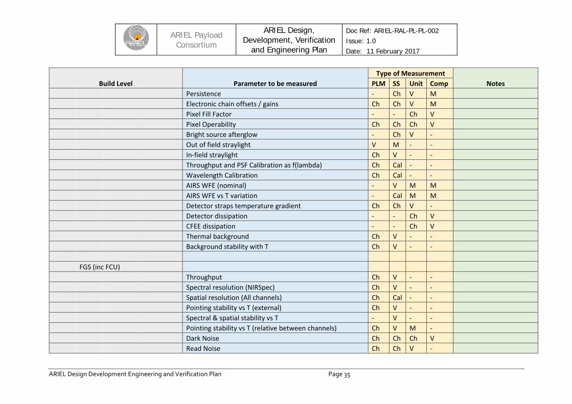
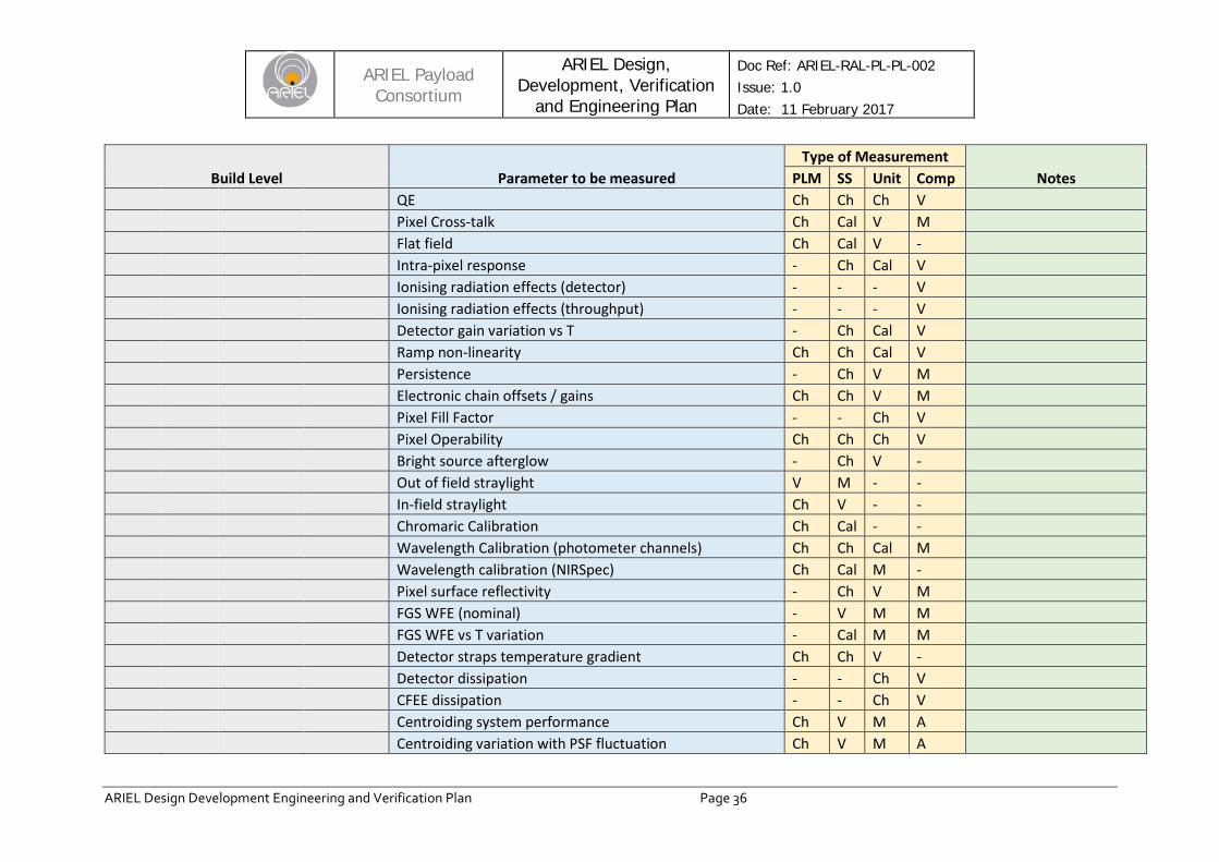
ANNEX A: VERIFICATION AND CALIBRATION PRELIMINARY PLANNING TABLE
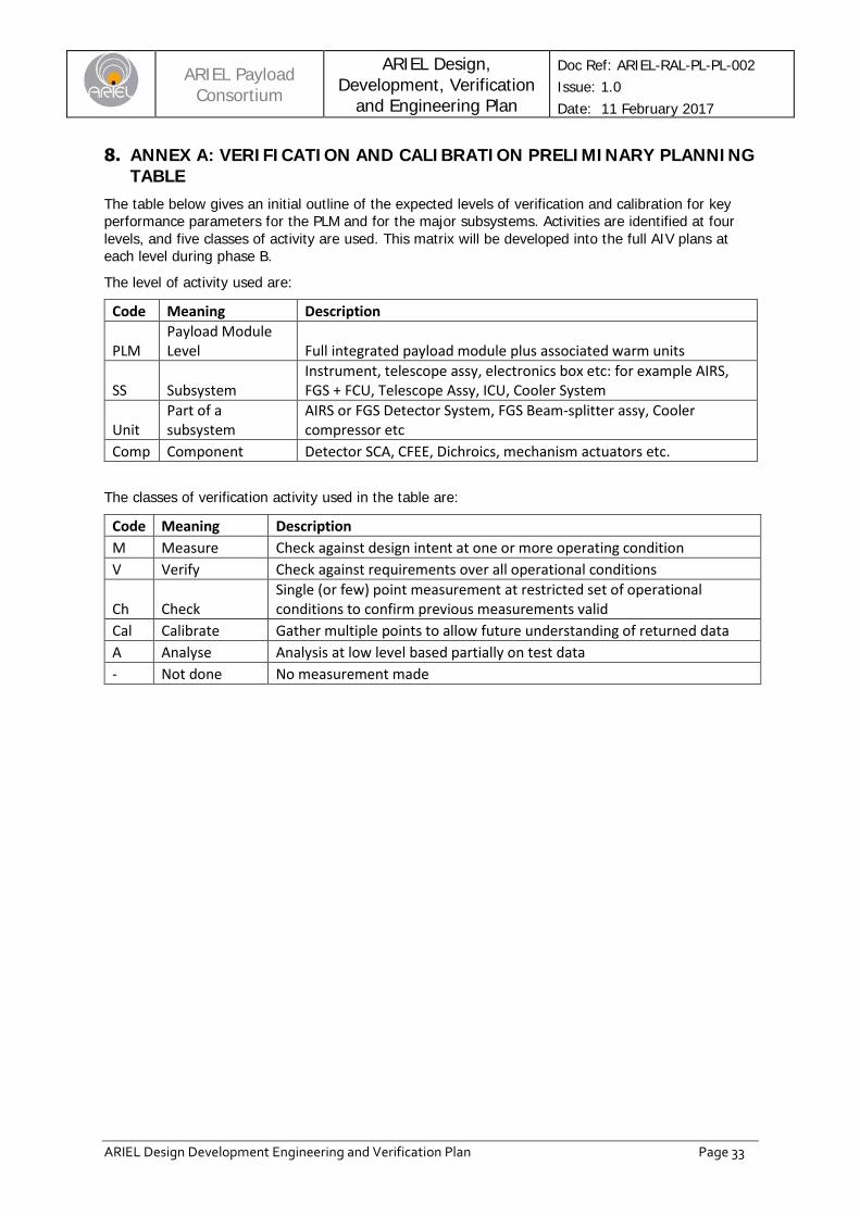
The table below gives an initial outline of the expected levels of verification and calibration for key performance parameters for the PLM and for the major subsystems. Activities are identified at four levels, and five classes of activity are used. This matrix will be developed into the full AIV plans at each level during phase B.
The level of activity used are:
Code Meaning Description
PLM Payload Module Level Full integrated payload module plus associated warm units
SS Subsystem Instrument, telescope assy, electronics box etc: for example AIRS, FGS + FCU, Telescope Assy, ICU, Cooler System
Unit Part of a subsystem
AIRS or FGS Detector System, FGS Beam-splitter assy, Cooler compressor etc
Comp Component Detector SCA, CFEE, Dichroics, mechanism actuators etc. The classes of verification activity used in the table are:
Code Meaning Description M Measure Check against design intent at one or more operating condition V Verify Check against requirements over all operational conditions
Ch Check Single (or few) point measurement at restricted set of operational conditions to confirm previous measurements valid
Cal Calibrate Gather multiple points to allow future understanding of returned data A Analyse Analysis at low level based partially on test data - Not done No measurement made
ARIEL Payload
Consortium ARIEL Design,
Development, Verification and Engineering Plan
Doc Ref: ARIEL-RAL-PL-PL-002 Issue: 1.0 Date: 11 February 2017
ARIEL Design Development Engineering and Verification Plan Page 34
Build Level Parameter to be measured Type of Measurement
Notes PLM SS Unit Comp Payload Module System FoM (Throughput x QE) V - - - Spectral Resolutions Ch - - - Spectral Coverage & Overlap V - - - Functionality of all mechanisms Ch Jitter susceptability V - - - System diffraction limit Ch - - - Overall noise budget V - - - Relative pointing errors (AIRS / FGS) V - - - Relative pointing errors (AIRS / FGS) vs T Cal - - - AIRS (inc DCU) Throughput Ch V - M Spectral resolution Ch V - - Spatial resolution Ch Cal - - Pointing stability vs T - V - - Spectral & spatial stability vs T - V - - Dark Noise Ch Ch Ch V Read Noise Ch Ch V - QE Ch Ch Ch V Pixel Cross-talk Ch Cal V M Flat field Ch Cal V - Intra-pixel response - Ch Cal V Ionising radiation effects (detector) - - - V Ionising radiation effects (throughput) - - - V Detector gain variation vs T - Ch Cal V Ramp non-linearity Ch Ch Cal V
ARIEL Payload
Consortium ARIEL Design,
Development, Verification and Engineering Plan
Doc Ref: ARIEL-RAL-PL-PL-002 Issue: 1.0 Date: 11 February 2017
ARIEL Design Development Engineering and Verification Plan Page 35
Build Level Parameter to be measured Type of Measurement
Notes PLM SS Unit Comp Persistence - Ch V M Electronic chain offsets / gains Ch Ch V M Pixel Fill Factor - - Ch V Pixel Operability Ch Ch Ch V Bright source afterglow - Ch V - Out of field straylight V M - - In-field straylight Ch V - - Throughput and PSF Calibration as f(lambda) Ch Cal - - Wavelength Calibration Ch Cal - - AIRS WFE (nominal) - V M M AIRS WFE vs T variation - Cal M M Detector straps temperature gradient Ch Ch V - Detector dissipation - - Ch V CFEE dissipation - - Ch V Thermal background Ch V - - Background stability with T Ch V - - FGS (inc FCU) Throughput Ch V - - Spectral resolution (NIRSpec) Ch V - - Spatial resolution (All channels) Ch Cal - - Pointing stability vs T (external) Ch V - - Spectral & spatial stability vs T - V - - Pointing stability vs T (relative between channels) Ch V M - Dark Noise Ch Ch Ch V Read Noise Ch Ch V -
ARIEL Payload
Consortium ARIEL Design,
Development, Verification and Engineering Plan
Doc Ref: ARIEL-RAL-PL-PL-002 Issue: 1.0 Date: 11 February 2017
ARIEL Design Development Engineering and Verification Plan Page 36
Build Level Parameter to be measured Type of Measurement
Notes PLM SS Unit Comp QE Ch Ch Ch V Pixel Cross-talk Ch Cal V M Flat field Ch Cal V - Intra-pixel response - Ch Cal V Ionising radiation effects (detector) - - - V Ionising radiation effects (throughput) - - - V Detector gain variation vs T - Ch Cal V Ramp non-linearity Ch Ch Cal V Persistence - Ch V M Electronic chain offsets / gains Ch Ch V M Pixel Fill Factor - - Ch V Pixel Operability Ch Ch Ch V Bright source afterglow - Ch V - Out of field straylight V M - - In-field straylight Ch V - - Chromaric Calibration Ch Cal - - Wavelength Calibration (photometer channels) Ch Ch Cal M Wavelength calibration (NIRSpec) Ch Cal M - Pixel surface reflectivity - Ch V M FGS WFE (nominal) - V M M FGS WFE vs T variation - Cal M M Detector straps temperature gradient Ch Ch V - Detector dissipation - - Ch V CFEE dissipation - - Ch V Centroiding system performance Ch V M A Centroiding variation with PSF fluctuation Ch V M A

ARIEL Payload
Consortium ARIEL Design,
Development, Verification and Engineering Plan
Doc Ref: ARIEL-RAL-PL-PL-002 Issue: 1.0 Date: 11 February 2017
ARIEL Design Development Engineering and Verification Plan Page 37
Build Level Parameter to be measured Type of Measurement
Notes PLM SS Unit Comp Telescope Assy (inc TCU) WFE at Ambient in 1G Ch V - - Gravity WFE sensitivity - V - - WFE at operating temp in 1G Ch V - - Thermal stability under changing operational conditions Ch V - - Decontamination mode demonstration - V - - PSF variation with T - V - - Out of field straylight rejection - V A - Throughput (BOL) vs wavelength Ch V - - Pointing variation with T Ch V - - M1 Mirror WFE at Ambient in 1G - Ch V - Gravity WFE sensitivity - Ch V A WFE at operating temp in 1G Ch V - - M2 Mirror WFE at Ambient in 1G - Ch V V WFE at operating temp in 1G Ch Ch V - M2M Range of motion Ch Ch V - Accuracy of position Ch Ch V - Power dissipation Ch Ch V - Stability vs T - Ch V - Ambient to Operating T offset - Ch V - M2 WFE at operating T in 1G Ch Ch V - V-Grooves & Bipods Thermal Performance V - - -

ARIEL Payload
Consortium ARIEL Design,
Development, Verification and Engineering Plan
Doc Ref: ARIEL-RAL-PL-PL-002 Issue: 1.0 Date: 11 February 2017
ARIEL Design Development Engineering and Verification Plan Page 38
Build Level Parameter to be measured Type of Measurement
Notes PLM SS Unit Comp Opto-mechanical stability V - - - Bi-pod structural design V - - - Cooler Thermal performance and margins Ch V - - Exported vibration Ch V M - EMC performance - V M - Compressor Assembly Range and performance - Ch V - Power dissipation - Ch V - Stability across operating temperature range - Ch V - Heat sink & pipework Heat transfer coefficients & performance Ch Ch V - Handling and gas transfer cleanliness Ch Ch V -
Cooler Control Electronics
EMC performance - V M - Vibration cancellig performance Ch Ch V - Power disipation Ch Ch V - Operation across temperature range - Ch V -