Argonne National Laboratory, with facilities in the states ...
114
Transcript of Argonne National Laboratory, with facilities in the states ...


Argonne National Laboratory, with facilities in the states of Illinois and Idaho, is owned by the United StatesGovernment and operated by The University of Chicago under the provisions of a contract with the Department ofEnergy.
DISCLAIMERThis report was prepared as an account of work sponsored by an agency of the United States Government. Neither the UnitedStates Government nor any agency thereof, nor The University of Chicago, nor any of their employees or officers, makes anywarranty, express or implied, or assumes any legal liability or responsibility for the accuracy, completeness, or usefulness ofany information, apparatus, product, or process disclosed, or represents that its use would not infringe privately owned rights.Reference herein to any specific commercial product, process, or service by trade name, trademark, manufacturer, or otherwise,does not necessarily constitute or imply its endorsement, recommendation, or favoring by the United States Government orany agency thereof. The views and opinions of document authors expressed herein do not necessarily state or reflect those ofthe United States Government or any agency thereof, Argonne National Laboratory, or The University of Chicago.
Available electronically at http://www.doe.gov/bridge
Available for a processing fee to U.S. Department of Energyand its contractors, in paper, from:
U.S. Department of EnergyOffice of Scientific and Technical InformationP.O. Box 62Oak Ridge, TN 37831-0062
phone: (865) 576-8401fax: (865) 576-5728email: [email protected]
Scientists in the ChemicalEngineering Division have developedan energy-efficient cerium-basedcatalyst that can remove up to 95-100% of the nitrogen oxide emissionsin exhaust. Moreover, unlike manyother catalysts, it works at normalexhaust temperatures and is moreeffective with water vapor present.
The UREX+ aqueous solventextraction process, being developedby the Chemical Engineering Division,is one of two Argonne technologiesbeing developed to reduce by morethan 95 percent the mass of high-levelwaste slated to be stored in the YuccaMountain nuclear waste repository.The goal is to delay or avoid theneed for a second repository. Thework is part of the Advanced FuelCycle Initiative.
The FASTER (Feasibility ofAcceptable Start Time ExperimentalReformer) project at ArgonneNational Laboratory is a collaborativeproject with three other NationalLaboratories, and academic andcommercial organizations. Theproject is designed to study thefeasibility of fast-starting gasolinefuel processors for automotive fuelcell systems, and to provide dataand recommendations for DOE’sGo/NoGo decision to continueon-board fuel processor development.

ANL-04/06
Argonne National Laboratory9700 South Cass AvenueArgonne, IL 60439
2003
Chemical Engineering Division
Annual Technical Report
David Lewis Division DirectorDiane Graziano Deputy Division DirectorJames F. Miller Associate Division DirectorGeorge Vandegrift Associate Division Director
March 2004
www.cmt.anl.gov


iii
CONTENTS
PageINTRODUCTION................................................................................................................................. 1
BATTERIES.......................................................................................................................................... 3High-Power Lithium-Ion Batteries for Transportation............................................................. 5Advanced Electrode Materials for Lithium-Ion Batteries ........................................................ 7High-Energy Batteries for Biomedical and Specialty Applications ......................................... 9Battery Testing and Evaluation ................................................................................................ 11
FUEL CELLS........................................................................................................................................ 13Fuel Processor Engineering...................................................................................................... 15Fuel Processor Catalysis........................................................................................................... 17Fuel Cell Systems Analysis ...................................................................................................... 19Hydrogen and Fuel Cell Materials ........................................................................................... 21Solid Oxide Fuel Cells.............................................................................................................. 23Fuel Cell Testing and Evaluation ............................................................................................. 25Fuel Cell Technical Analysis.................................................................................................... 27
PROCESS CHEMISTRY AND ENGINEERING ................................................................................ 29UREX+ Process Demonstration ............................................................................................... 31Molybdenum-99 Production from Low-Enriched Uranium..................................................... 33R&D Support for Savannah River Site Salt Processing Project............................................... 35Crystal Chemistry of Trace Elements in Spent Nuclear Fuel................................................... 37EBR-II Waste Forms Qualification Testing ............................................................................. 39Human-Detoxification System ................................................................................................. 41
NUCLEAR TECHNOLOGY ................................................................................................................ 43Oxide Reduction to Convert Spent Oxide Fuel to Metal.......................................................... 45Structural Materials to Enable Electrolytic Reduction of Spent Oxide
Nuclear Fuel in a Molten Salt Electrolyte ........................................................................... 47Pyroprocess-Based Treatment of Spent Nuclear Fuel: Process
and Equipment Integration .................................................................................................. 49Pyroprocess-Based Treatment of Spent Nuclear Fuel: Planar Electrode
Electrorefiner Development ................................................................................................ 53Recovery of Actinides from Spent Fuel by Electrolysis .......................................................... 55
NATIONAL SECURITY...................................................................................................................... 57Domestic Nuclear Event Attribution Program ......................................................................... 59Radiological Dispersive Device Materials Training Program.................................................. 61
BASIC AND APPLIED SCIENCES..................................................................................................... 63Reel-to-Reel Raman Microscopy of Long-Length Superconducting Tapes............................. 65Bifunctional Catalyst to Reduce Emissions of Nitrogen Oxides.............................................. 67Supercritical Carbon Monoxide Hydrogenation....................................................................... 69In Situ NMR Analysis of Graphite Insertion Electrodes .......................................................... 71

iv
CONTENTS (Cont.)
PageANALYTICAL CHEMISTRY LABORATORY ................................................................................. 73
Performance Demonstration Program for the Analysis of SimulatedHeadspace Gases for the Waste Isolation Pilot Plant Project .............................................. 75
Tritium Target Qualification Project ........................................................................................ 77Distribution Coefficient Measurements of Soils ...................................................................... 79Isotopic Analysis of High-Burnup Spent Nuclear Fuel............................................................ 81
PATENTS AND SELECTED PUBLICATIONS AND PRESENTATIONS....................................... 83

1
Introduction
The Chemical Engineering Division is one of sixdivisions within the Engineering ResearchDirectorate at Argonne National Laboratory, oneof the U.S. government’s oldest and largestresearch laboratories. The University of Chicagooversees the laboratory on behalf of the U.S.Department of Energy (DOE). Argonne’smission is to conduct basic scientific research, tooperate national scientific facilities, to enhancethe nation’s energy resources, to promotenational security, and to develop better ways tomanage environmental problems. Argonne hasthe further responsibility of strengthening thenation’s technology base by developinginnovative technology and transferring it toindustry.
The Division is a diverse early-stage engineeringorganization, specializing in the treatment ofspent nuclear fuel, development of advancedelectrochemical power sources, and managementof both high- and low-level nuclear wastes.Additionally, the Division operates theAnalytical Chemistry Laboratory, whichprovides a broad range of analytical services toArgonne and other organizations.
The Division is multidisciplinary. Its peoplehave formal training in chemistry; physics;materials science; and electrical, mechanical,chemical, and nuclear engineeing. They arespecialists in electrochemistry, ceramics,metallurgy, catalysis, materials characterization,nuclear magnetic resonance, repository science,and the nuclear fuel cycle. Our staff haveexperience working in and collaborating withuniversity, industry and government researchand development laboratories throughout theworld.
Our wide-ranging expertise finds readyapplication in solving energy, national security,and environmental problems. Division personnelare frequently called on by governmental andindustrial organizations for advice and
contributions to problem solving in areas thatintersect present and past Division programs andactivities.
Currently, we are engaged in the development ofseveral technologies of national importance.Included among them are:
• Advanced lithium-ion and lithium-polymerbatteries for transportation and otherapplications,
• Fuel cells, including the use of an oxidativereformer with gasoline as the fuel supply,
• Production and storage technologies criticalto the hydrogen economy,
• Stable nuclear waste forms suitable forstorage in a geological repository,
• Threat attribution and training relative toradioactive dispersal devices (“dirtybombs”), and
• Aqueous and pyrochemical processes for thedisposition of spent nuclear fuel.
Other important programs are focused insuperconductivity, catalysis, nanotechnology,and nuclear materials.
During fiscal year 2003, CMT had an annualoperating budget of approximately $36 million.Of that, more than 90% was from DOE and theremainder from other government agencies andprivate industry.
Displayed below is an overview organizationchart of the Division. A complete organizationchart appears at the end of this report.
In this annual report we present an overview ofthe technical programs together withrepresentative highlights. The report is notintended to be comprehensive or encyclopedic,but to serve as an indication of the condition andstatus of the Division.

2
D. LewisDirector
Nuclear Fuel CyclePrograms
Electrochemical Technology and Basic Science Programs
SupportSystems
NuclearTechnology
Process Chemistry and Engineering
NationalSecurity
BatteryTechnology
Fuel CellTechnology
Basic and AppliedSciences
Administration
HealthPhysics
Analytical Chemistry Laboratory

3
Batteries
Rechargeable lithium batteries have becomevery popular as power sources for consumerelectronic devices, because of their high energydensity (energy per unit weight or volume)relative to nickel cadmium and nickel metalhydride batteries. Cellular telephones, digitalcameras, camcorders, laptop computers, andother electronic devices currently use lithium-ion batteries. Due to their success in theseapplications, they are under development forother applications such as energy storagedevices for electric vehicles, hybrid electricvehicles, and specialty battery applications.
Transportation: A Historical Perspective
The Chemical Engineering Division (theDivision) has been involved in the developmentof advanced lithium batteries for transportationapplications since 1994. Our early work was onlithium-polymer batteries that employed metalliclithium negative electrodes, a polyethyleneoxide solid electrolyte, and a metal oxidepositive electrode. This technology was beingdeveloped for use in electric vehicles (EVs)under a cooperative research and developmentagreement, or CRADA, with 3M Corporationand Hydro-Quebec. The U.S. Advanced BatteryConsortium (comprising DaimlerChrysler, FordMotor Company, and General MotorsCorporation) and the U.S. Department of Energy(DOE) sponsored this research and development(R&D) from 1994 to 2001.
In 1998, the Division helped DOE to organizeand initiate a new multi-national-laboratoryR&D program (the Advanced TechnologyDevelopment or ATD Program) on high-powerlithium-ion batteries. Lithium-ion batteriesemploy a liquid or gel-polymer electrolyte andlithium insertion compounds in both the positiveand negative electrodes. The development ofhigh-power lithium-ion batteries for hybridelectric vehicle (HEV) applications was begununder the Partnership for a New Generation of
Vehicles (PNGV) Program. This program was afederal government/U.S. auto industrypartnership to develop low-emission full-sizepassenger vehicles with an 80-mile-per-gallonfuel economy. The PNGV Program focused onthe development of HEVs, which employ anenergy storage device to level the load on theinternal combustion engine and recaptureregenerative braking energy. The ATD Program,was initiated to assist PNGV industrialdevelopers of high-power lithium-ion batteriesovercome the barriers of life, abuse tolerance,and cost for this promising technology. TheATD Program covers a broad range of R&Dactivities associated with understanding themechanisms that limit life and abuse tolerance,as well as evaluating and developing advancedmaterials designed to overcome theselimitations, while simultaneously reducingmaterial costs. It also involves the developmentof novel approaches for reducing cell packagingcosts.
Transportation Research Today
In 2002, the PNGV Program was replaced by anew auto industry/federal governmentpartnership, denoted the FreedomCARPartnership. It expands on the PNGV Program,
Battery R&DTransportation (Hybrid/Fuel-Cell ElectricVehicles)• Understand life and safety limiting mechanisms• Develop novel materials and advanced cell
chemistries to enhance power, life, and safety,while reducing cost
• Develop innovative approaches for reducingbattery cell packaging costs
Specialty Applications• Develop advanced lithium battery chemistries
for biomedical, space, and military applications• Develop advanced electrolyte systems with
more stable salts

4
with a long-term focus on the development offuel cell electric vehicles (FCEVs), while itcontinues to support the development of HEVtechnologies in the nearer term. DOE’s ATDProgram continues to address the high-powerlithium-ion battery needs for HEV and FCEVapplications. The Division continues work onthe ATD Program under the FreedomCARPartnership and is expanding its efforts to studylow-temperature performance.
Additionally, the Division conducts longer-range, but focused, research on advancedmaterials for lithium batteries. These longer-range research activities seek to develop novelnew materials that can enhance the performance,life, and/or safety of advanced lithium batteries,while reducing cost. In recent years, a newfamily of intermetallic negative electrodematerials was discovered, as was a new familyof layered metal oxide positive electrodematerials. We continue our efforts to developoptimal electrode compositions for both high-power and high-energy lithium batteries for usein transportation applications.
Specialty Applications
The Division works collaboratively withindustry on rechargeable lithium batteries forspecialty applications. In a major project fundedby the Department of Commerce, AdvancedTechnology Program, the Division is undercontract to the industrial leader of the project todevelop advanced cell chemistries for long-liferechargeable lithium microbatteries. Themicrobatteries will be used as the power sourcein neuromuscular microstimulator implantsknown as bions®.
These microstimulators may be used to treatpatients suffering from stroke, Parkinson’sdisease, epilepsy, urinary urge incontinence, andmany other conditions involving muscularimpairment. The primary cell chemistry involvesa new polymer electrolyte that has high ionicconductivity at room temperature, while the
back-up chemistry employs a more conventionallong-life liquid electrolyte system.
During the last year, the Division implementedthree new industrial contracts. One of thecontracts deals with the development of a newsalt-based electrolyte system for use in lithium-ion batteries. A second contract deals with thedevelopment of a more optimal cell chemistryfor use in military applications. The thirdcontract deals with the development ofelectrolyte additives that can stabilize the cellchemistries used in secondary lithium batteriesbeing developed for satellite applications.
Additionally, the Division operates theElectrochemical Analysis and DiagnosticsLaboratory, which was established by DOE toconduct independent evaluations of advancedbattery systems for applications such as EV,HEV, FCEV, and stationary energy storage. Thisfacility has been cited as a valuable resource bybattery users, developers, and DOE programmanagers, who must evaluate and make choicesregarding competing battery technologies andresearch directions. Since it was establishedmore than two decades ago, the laboratory hastested more than 4,000 cells and batteries,ranging from individual 4-Wh cells to 50-kWhbatteries, representing numerous technologiesand battery developers. The test facility hasexpanded to include the testing and evaluation offuel cell stacks and fuel cell systems up to80 kW.
For More Information
Gary Henriksen, HeadBattery Technology DepartmentChemical Engineering DivisionArgonne National Laboratory9700 S. Cass Ave.Argonne, IL 60439630-252-4591, fax [email protected]/science-technology/batteries

5
High-Power Lithium-Ion Batteries for Transportation
Safer, longer-lived and less costly batteries for hybrid electric vehicles
Better high-power batteries are needed to levelthe load and recapture regenerative brakingenergy in hybrid electric vehicle (HEV) and fuelcell electric vehicle systems, currently underdevelopment internationally for transportationapplications. Although a few production HEVshave been introduced into the automotivemarket, no current battery technologydemonstrates an acceptable combination ofefficiency, life, safety, and cost for large-scalecommercialization of HEVs.
As part of the FreedomCAR Partnershipbetween the U.S. Department of Energy (DOE)and the U.S. automobile manufacturers,Argonne’s Chemical Engineering Division (theDivision) and four other DOE laboratories areconducting research and development to helpindustrial battery developers reduce the cost andenhance the calendar life and inherent safety ofhigh-power lithium-ion HEV batteries. Ourapproach is to develop more stable cellcomponents and chemistries that employ lower-cost materials; incorporate them into sealedcells; conduct well-defined abuse, low-temperature performance, and accelerated agingtests on the cells; and then employ a suite ofsophisticated diagnostic tools and techniques toidentify the main factors that control life andabuse tolerance. The diagnostic results are usedby the Division to identify and develop moreoptimal materials and cell chemistries for thishigh-power application.
2003 Research Highlights
This year we made significant progress in under-standing the factors that limit the life of oursecond-generation baseline cell chemistry. Thiscell chemistry is shown in Table 1. Average cellaging data are provided in Figure 1. Many of theaged second-generation cells underwent detaileddiagnostic evaluations to understand the agingmechanisms in this cell chemistry.
Table 1. Chemistry Incorporated in Second-Generation Baseline Cells
Component Material
Anode 92 wt% MAG-10 graphite8 wt% PVDF binder
Cathode 84 wt% LiNi0.8Co0.15Al0.05O24 wt% SFG-6 graphite4 wt% carbon black8 wt% PVDF binder
Electrolyte 1.2M LiPF6 in EC:EMC (3:7)PVDF = polyvinylidene fluoride, EC = ethylenecarbonate, EMC = ethyl methyl carbonate
25
30
35
40
45
50
55
60
0 20 40 60 80
Time, weeks
Avg
. AS
I, o
hm
-cm
2
Baseline
calendar life 45 o C
Baseline
calendar life 55 o CBaseline
cycle life 45 o C
Baseline
cycle life 25 o C
25
30
35
40
45
50
55
60
0 20 40 60 80
Time, weeks
Avg
. AS
I, o
hm
-cm
2
Baseline
calendar life 45 o C
Baseline
calendar life 55 o CBaseline
cycle life 45 o C
Baseline
cycle life 25 o C
Fig. 1. Average cell aging characteristics—impedance vs. aging time at temperature.
Prior reference electrode studies, showed thatthe majority of the cell impedance rise duringaging occurred at the cathode and our diagnosticstudies focused on this electrode. Electro-chemical impedance spectroscopy (EIS) of newand aged cathodes showed different phenomenaduring the early (low-rate impedance rise) stagevs. the late (high-rate impedance rise) stage ofcell aging. During the early stage, most of theimpedance rise is associated with an increase inthe mid-frequency arc (see Fig. 2), which is aninterfacial impedance. During the late stage, the

6
low-frequency tail (see Fig. 3) becomes domi-nant. This low-frequency tail is associated withdiffusional phenomena. ANL’s cell transportmodel was used to study both features of the EISdata and to identify responsible phenomena.
0
50
100
150
200
250
300
350
400
450
0 20 40 60 80 100 120 140 160Z(Re), ASI
Z(Im
), A
SI
0% PF41% PF
0.0001 Hz
0.001 Hz
0
50
100
150
200
250
300
350
400
450
0 20 40 60 80 100 120 140 160Z(Re), ASI
Z(Im
), A
SI
0% PF41% PF
0.0001 Hz
0.001 Hz
Fig. 3. Late-stage EIS data on aged cells
The main phenomenon identified and studiedextensively is the development of organicsurface films on the cathode. These films wereobserved via high-resolution scanning electronmicroscopy and transmission electronmicroscopy (HR-TEM). X-ray photoelectronspectroscopy studies showed that chemicalchanges in these films occur in a manner thatdirectly correlates with the amount of cellimpedance rise and power fade. Scraping of thecathode surfaces was found to re-expose thecathode active material, thereby verifying thepresence of films covering the active cathodematerial in aged cells.
Various other diagnostic studies were performedon cathodes that were harvested from new andaged cells. X-ray diffraction studies showed thatthe structure of the bulk cathode material wasessentially unchanged during the aging process.HR-TEM studies showed limited evidence ofparticle cracking in cathodes harvested fromcells with extreme (>50%) power fade. HR-TEM and EELS showed that the virgin cathodematerial contains a thin (5- to 10-nm) NiO crust(outer layer) on the surface of the cathodeparticles and the thickness of this crust remainedconstant (did not increase) during the agingprocess.
Based on these results, it appears that theorganic surface films on the cathodes are playinga significant role in the impedance rise andpower fade of these high-power cells. It ispossible that these films impede Li+
diffusion/migration to the surface of the cathodewhere the electron exchange reaction occurs. Asthe surface of the active cathode particlesbecomes more thoroughly covered by thesefilms, the impedance of the cathode increases.Additional studies are being performed to verifythe role that these films play in the impedancerise and power fade of the cathode during aging.
This research is funded by the U.S. Departmentof Energy, Office of Energy Efficiency andRenewable Energy, FreedomCAR and VehicleTechnologies Office. Other participating DOElaboratories include Brookhaven, Idaho NationalEngineering and Environmental, LawrenceBerkeley, and Sandia National Laboratories.
Research Participants
Daniel P. Abraham, Khalil Amine, IliasBelharouak, Ira D. Bloom, David J. Chaiko,Dennis W. Dees, Evren Gunen, Gary L.Henriksen, Yoo-Eup Hyung, Andrew Jansen,Christopher S. Johnson, Scott A. Jones, ArthurKahaian, Sun-Ho Kang, Jeom-Soo Kim, JunLiu, Paul A. Nelson, Bookean Oh, Emo Redey,Michael M. Thackeray, and Donald R. Vissers.For more information, contact Gary Henriksen(630-252-4591, [email protected]).
EIS for G2.60C55.A215.33.36.35.G.A
0
0.005
0.01
0.015
0.02
0.025
0.03
0.005 0.01 0.015 0.02 0.025 0.03 0.035 0.04
Zreal, ohms
-Zim
ag, o
hm
s
Characterization t = 0
RPT #1 t = 4 weeks
RPT #2 t = 8 weeks
RPT #3 t = 12 weeks
RPT #4 t = 16 weeks
RPT #5 t = 20 weeks
RPT #6 t = 24 weeks
RPT #7 t = 28 weeks
RPT #8 t = 32 weeks
RPT #9 t = 36 weeks
mid-freq min
high freq min
Fig. 2. Early-stage EIS data on aged cells.

7
Advanced Electrode Materials for Lithium-Ion Batteries
Finding new materials to optimize electrochemical reactions
Materials play a key role in the development ofadvanced lithium-ion batteries for transportationand other special applications. The ChemicalEngineering Division conducts long-rangeresearch aimed at the development of novelmaterials that can enhance the performance, life,and safety of lithium batteries while reducingcost. In recent years, the Division has discoveredseveral new intermetallic negative electrodematerials and has improved the electrochemicalproperties of metal oxide positive electrodes bycompositional modification of their structures orsurface treatment. We are continuing our effortsto develop these materials—and to discover newones—to provide optimal electrode performancethat developers require in lithium-ion batteries.
2003 Research Highlights
Stabilized LiMn2O4 Spinel Electrodes
Despite its superior rate capability and structuraland thermal stability compared with layeredLiCoO2 and LiNiO2 electrodes, the solubility ofLiMn2O4 spinel electrodes in lithium-ion batteryelectrolytes has precluded their widespread usein commercial cells.
Recent technological advances have been madein improving the cycling stability of LiMn2O4
(i.e. A[B2]O4 spinel structure) electrodes byeither A-site and/or B-site substitution incombination with metal-oxide coating of thematerial. This dual approach combats thesolubility problems and instability encounteredby the spinel electrode in application.
We have used colloidal metal-oxide suspensionsof zirconia, alumina and silica to coat LiMn2O4-and substituted Li1.05M0.05Mn1.9O4 (M = Al, Ni)powders. The coated powders are annealed at400 °C and then made into electrodes. Using thistechnique, it is possible to control the surface
architecture of the coating in terms of thicknessand porosity. Our initial results have shown thatZrO2-coated spinel electrodes consistentlyprovide superior performance compared withthose coated with SiO2 or Al2O3. The inferiorelectrochemical behavior of SiO2 and Al2O3-coated electrodes is attributed to a sinteringreaction that occurs between the LiMn2O4
particles and the nanosized SiO2 (~2 nm) andAl2O3 (<20 nm) particles during the annealingstep, which apparently does not occur whenZrO2 (<4 nm) particles are used.
The voltage profiles for the initial discharge ofLi/LiMn2O4- and Li/Li1.05M0.05Mn1.9O4 cells,cycled between 4.3 and 3.3 V at 50 °C, withuncoated spinel electrodes and electrodes coatedwith 4 wt% ZrO2 are compared in Figure 1. Thespecific capacity of coated electrodes (based onthe mass of the active spinel electrode and theZrO2 coating) is lower than that of uncoatedelectrodes, as expected, because the coating iselectrochemically inert and should increasepolarization effects at the electrode surfaceduring electrochemical discharge. The point ofinflection that occurs approximately halfwayalong the discharge curve of the Li/LiMn2O4 cellis attributed to Li+- and electronic ordering ofthe manganese ions when the spinel electrodereaches the composition Li0.5Mn2O4; thisinflection is smoothed in cells with substitutedelectrodes, consistent with earlier reports in theliterature. In these instances, the voltage profileadopts greater single-phase character in thehigher voltage region, in contrast to the two-phase behavior of Li1-xMn2O4 electrodes for0.5≤x≤1, supporting the argument thatsubstitution for Mn by the M ions inLi1.05M0.05Mn1.90O4 electrodes disrupts the long-range atomic and electronic order within thespinel structure, thereby suppressing theordering process during the electrochemicalextraction and reinsertion of lithium.

8
0 20 40 60 80 100 120
3.4
3.6
3.8
4.0
4.2
10 20 30 40 50 60 703.95
4.00
4.05
4.10
4.15
E, V
(vs.
Li/L
i+ )
Capacity, mAh/g
50oC
0 20 40 60 80 100 120
3.4
3.6
3.8
4.0
4.2
10 20 30 40 50 60 703.95
4.00
4.05
4.10
4.15
E, V
(vs.
Li/L
i+ )
Capacity, mAh/g
50oC
mAh/g
E, V
0 20 40 60 80 100 120
3.4
3.6
3.8
4.0
4.2
10 20 30 40 50 60 703.95
4.00
4.05
4.10
4.15
E, V
(vs.
Li/L
i+ )
Capacity, mAh/g
50oC
0 20 40 60 80 100 120
3.4
3.6
3.8
4.0
4.2
10 20 30 40 50 60 703.95
4.00
4.05
4.10
4.15
E, V
(vs.
Li/L
i+ )
Capacity, mAh/g
50oC
mAh/g
E, V
Fig. 1. Initial discharge profiles of lithium cells at50 °C with uncoated (large symbol) andcoated (small symbol) LiMn2O4 (-),Li1.05Al0.05Mn1.90O4 (∆) andLi1.05Ni0.05Mn1.90O4 (
Capacity vs. cycle number plots of Li/spinelcells containing uncoated LiMn2O4, ZrO2-coatedLiMn2O4 and ZrO2-coated Li1.05Ni0.05Mn1.90O4
electrodes are shown in Fig. 2 (50 °C). The datademonstrate that the coated, substituted spinelelectrode provides greater cycling stability thanboth coated and uncoated LiMn2O4 electrodes.
10 20 30 40 50 600
20
40
60
80
100
120
140
Cap
acity
, mah
/g
Number of Cycles
ZrO2-coated Li1.05Ni0.05Mn1.9O4
4.3-3.3V 50oC
Uncoated LiMn2O4
ZrO2-coated LiMn2O4
10 20 30 40 50 600
20
40
60
80
100
120
140
Cap
acity
, mah
/g
Number of Cycles
ZrO2-coated Li1.05Ni0.05Mn1.9O4
50C
Uncoated LiMn2O4
ZrO2-coated LiMn2O4
10 20 30 40 50 600
20
40
60
80
100
120
140
10 20 30 40 50 600
20
40
60
80
100
120
140
Cap
acity
, mah
/g
Number of Cycles
ZrO2-coated Li1.05Ni0.05Mn1.9O4
4.3-3.3V 50oC
Uncoated LiMn2O4
ZrO2-coated LiMn2O4
10 20 30 40 50 600
20
40
60
80
100
120
140
Uncoated LiMn2O4
ZrO2-coated LiMn2O4
10 20 30 40 50 600
20
40
60
80
100
120
140
Cap
acity
, mah
/g
Number of Cycles
ZrO2-coated Li1.05Ni0.05Mn1.9O4
50C
Uncoated LiMn2O4
ZrO2-coated LiMn2O4
Fig. 2. Capacity vs. cycle number plots for lithiumcells cycled between 4.3 and 3.3 V at 50 °C :uncoated LiMn2O4; ZrO2-coated LiMn2O4;and ZrO2-coated Li1.05Ni0.05Mn1.90O4.
Coatings deposited from colloidal suspensionsfeature thicknesses that vary over a wide range,typically from 10 to 50 nm. A high-resolution
transmission electron microscope (TEM) imageof a ZrO2-coated LiMn2O4 electrode that hadbeen annealed at 400 °C provides little evidenceof ZrO2 reaction with, or fusion to, the spinelparticles (Fig. 3). A magnified image, inset inFigure 3, shows that the coatings consist of aporous conglomerate of ZrO2 primary particlesless than 4 nm in dimension. The combination ofa porous coating that allows access of theelectrolyte to the spinel electrode, and the highsurface area of the ZrO2 particles and theiraffinity for scavenging HF and H2O moleculesfrom the electrolyte appear to be among thereasons why ZrO2 coatings are proving to bemost effective in stabilizing the cycling stabilityof LiMn2O4 spinel electrodes. Products of ZrO2
reacted with HF/H2O could result in oxonium-zirconium-fluoride-hydrate structures, such as[ZrF5
-•H3O+•2H2O]. This product is
reformulated as a ZrO2•5HF•H2O compound(component notation) in order to emphasize thestabilizing properties that an amphoteric ZrO2
coating provides.
100 nm
ZrO2
8 nm
Spinelparticles
100 nm100 nm
ZrO2
8 nm8 nm
Spinelparticles (a)
100 nm
ZrO2
8 nm
Spinelparticles
100 nm100 nm
ZrO2
8 nm8 nm
Spinelparticles (a)
100 nm
ZrO2
8 nm
Spinelparticles
100 nm100 nm
ZrO2
8 nm8 nm
Spinelparticles (a)
100 nm
ZrO2
8 nm
Spinelparticles
100 nm100 nm
ZrO2
8 nm8 nm
Spinelparticles (a)
100 nm
ZrO2
8 nm
Spinelparticles
100 nm100 nm
ZrO2
8 nm8 nm
Spinelparticles (a)
100 nm
ZrO2
8 nm
Spinelparticles
100 nm100 nm
ZrO2
8 nm8 nm
Spinelparticles (a)
Fig. 3. High-resolution TEM image of ZrO2-coatedLiMn2O4 spinel particles.
This research is funded by the U.S. Departmentof Energy, Office of Energy Efficiency andRenewable Energy, and Office of Science.
Research Participants
Michael M. Thackeray, Christopher S. Johnson,John T. Vaughey, Jeom-Soo Kim. For moreinformation, contact Michael Thackeray(630-252-9184, [email protected]).

9
High-Energy Batteries for Biomedical and Specialty Applications
Advanced materials help meet the requirements of several specialty applications
During the last year, the Chemical EngineeringDivision (the Division) was involved in severalcontracts with outside organizations (Work forOthers, or WFO, contracts) to develop advancedcell chemistries and cell components for high-energy lithium batteries. The largest of thecontracts is a 4-year NIST-ATP project withQuallion LLC. This project consists ofdeveloping battery chemistries for long-liferechargeable lithium polymer battery systems topower advanced micro-stimulators, such as thebion®.
Two other WFO contracts are directed atdeveloping long-life rechargeable lithiumpolymer and lithium ion batteries for use inmilitary and space applications, respectively. Inboth cases, the Division is developing cellchemistries. A fourth project involves thedevelopment of optimal solvent systems for anindustrial firm that has developed a new Li+
conducting salt that is thermally, chemically,and electrochemically more stable than theconventional LiPF6 salt. These new projectswere initiated only recently and will not bereported on this year.
The remainder of this subsection providesselected advances on the WFO project todevelop a long-life high-energy lithium-polymerbattery for use with bions. Implantable bionsoffer hope for victims of strokes, Parkinson’sdisease, epilepsy, urinary urge incontinence, andsimilar conditions involving neuromuscularimpairment.
2003 Research Highlights
Advanced polymer electrolyte: Working incollaboration with Quallion and the Universityof Wisconsin, the Division is developing newpoly(ethylene oxide) grafted siloxane polymers.These siloxane-based polymers exhibit very
good electrochemical, chemical, and thermalstability, as well as low toxicity. Our prior workshowed that these polymer electrolytes possessvery good room-temperature ionicconductivities, are stable over a wide voltagewindow, and exhibit significantly enhancedthermal stability relative to the conventionalliquid electrolyte systems used in lithium ioncells and batteries.
New siloxane phases with ionic conductivitiesnear 10-3 S/cm at room temperature are beingsynthesized and characterized. Figure 1 showsthe conductivity of one of these new siloxanepolymers as a function of temperature. Theseconductivities are similar to those forconventional liquid organic electrolytes used inlithium ion batteries. The outstanding electro-chemical stability of these polymer electrolytesoffers the opportunity to use them with advancedhigh capacity layered cathode materials with>250 mAh/g capacity density at 4.5 V. Figure 2provides a cyclic voltamogram on one of thenew siloxane polymers, showing the material is
1.0E-04
1.0E-03
1.0E-02
20 30 40 50 60 70 80
Temperature, oC
Ioni
c co
nduc
tivity
, S/c
m
Fig. 1. Lithium ion conductivity of siloxane polymerelectrolyte as a function of temperature.

10
0.8M LiBOB in siloxane 1st cycle CV (Pt/Li)
-1.0E-06
0.0E+00
1.0E-06
2.0E-06
3.0E-06
4.0E-06
5.0E-06
0 1 2 3 4 5 6
Voltage (V)
Cur
rent
den
sity
(A/c
m2)
Fig. 2. Cyclic voltamogram showing theelectrochemical stability of siloxane polymerbetween 0 and 6 V vs. lithium.
extremely stable between 0 and 6 volts vs.lithium. Additionally, these materials arenonflammable and non-toxic. These featurescombine to make the siloxane polymerelectrolytes attractive for use in long-lifebatteries for implantable medical devices. Also,their high ionic conductivities make them viablecandidates for other applications, e.g., satellites,consumer electronics, and smart cards.
Advanced cathodes: During the last year, werefined our LiFePO4 cathode material for use inthe new long-life battery system for the bions.The olivine cathode materials have greaterchemical and thermal stability in the presence ofconventional electrolytes and they exhibit bettersafety characteristics relative to the LiNi1-xCoxO2
type cathode materials. The olivine materials areelectronically insulating and we have optimizedthe performance of our material using a newprocess for coating the olivine with carbon at theparticle level.
Stable cell performance: Recent data on cellsthat employ a LiNi1-xCoxO2 type cathode, asiloxane polymer electrolyte system, and agraphite anode show excellent stability.Figure 3 provides capacity density andcoulombic efficiency data on a cell of this type.The high coulombic efficiency provides furtherverification of the stability of the siloxanepolymer electrolyte. Beginning early in theproject, we were able to achieve stableperformance from cells that employed lithiummetal anodes and during the last year we havesucceeded in transferring this level ofperformance stability to cells that employgraphite anode materials.
Fig. 3. Capacity density and efficiency vs. cyclenumber for a graphite/siloxane polymer/LiNi1-xCoxO2 cell.
Research Participants
Khalil Amine, Illias Belharouak, Gary L.Henriksen, Bookeun Oh, Sang Young Yoon,and Donald R. Vissers. For more informationcontact Khalil Amine (630-252-3838,[email protected]).

11
Battery Testing and Evaluation
Providing standardized, independent evaluations of advanced batteries
The Electrochemical Analysis and DiagnosticsLaboratory (EADL) in the ChemicalEngineering Division has been providing batterydevelopers with reliable, independent, andunbiased performance evaluations of their cells,modules, and battery packs since 1976. Theseevaluations have been performed for the U.S.Department of Energy (DOE), government andindustry consortia, and industrial developers toprovide insight into the factors that limit theperformance and life of advanced batterysystems. Recently, our capabilities haveexpanded to fuel cell testing (see “Fuel CellTesting and Evaluation” in the Fuel Cells sectionof this report).
The EADL is an extensive facility designed totest large numbers of both small and largebatteries and fuel cells designed within andoutside of Argonne National Laboratory. It isnow the only known facility with capabilities toconduct 120 concurrent advanced battery studiesunder operating conditions that simulate electric-vehicle (EV), electric-hybrid vehicle (HEV),utility load-leveling, and standby/uninterruptiblepower source applications. Each battery isindependently defined, controlled and monitoredto impose charging regimes and discharge loadprofiles that simulate the types of dynamicoperating conditions found during actual use.The testing of groups of cells/batteries iscontrolled by computers that communicate overhigh-speed networks with central servers and arecontrolled by other PC workstations.
The EADL has evaluated many different batterytechnologies, such as Na/S, LiAl/FeS,LiAl/FeS2, Li/polymer, Li-ion, Zn/Cl2, Zn/Br2,Ni/Fe, Ni/Zn, Ni/MH, Ni/Cd, and Pb-acid.These represent technologies from batterydevelopers throughout the world.
2003 Research Highlights
In a portion of our HEV work with Li-ionbatteries, we continued the calendar lifeevaluation of prototype lithium-ion batteriesmade under DOE's Advanced TechnologyDevelopment (ATD) Program. These batterieswere designed for use in hybrid electric vehicles.At present, lithium-ion technology exhibitsexceptional power capability and long cycle life,but has insufficient calendar life. One of thegoals for this project is to gain an understandingof the effect of cell chemistry on calendar life.For this work, two cell chemistries were used;the cell chemistry differed in the composition ofthe cathode. Group A cells contained aLiNi0.8Co0.15Al0.05O2 cathode and Group B,LiNi0.8Co0.10Al0.10O2. Accelerated calendar lifetests were used at 45 (Groups A and B) and55oC (Group A only) at 60% state of charge.
Initially, the average C/25 capacities for GroupsA and B were 1.03 ± 0.03 and 0.97 ± 0.02 Ah,respectively. As cells age, the C/25 capacityfades. The capacity fade data were plotted as afunction of t1/2, yielding straight lines withreasonable values of regression coefficients, r2
(see Fig. 1). From the graph, we can infer thatthe rate of C/25 capacity for both groups of cellsfollowed t1/2 kinetic laws at both testtemperatures and that the capacity fade rate ofGroup B cells is less than that of Group A cells.
0.65
0.70
0.75
0.80
0.85
0.90
0.95
1.00
1.05
1.10
0 20 40 60 80 100
Time, weeks
C/2
5 ca
pac
ity, A
h
Group BGroup A 55CGroup A 45C
Fig. 1. C/25 capacity vs. time for Groups A and B.

12
The initial average ASI values at 60% SOC were28.41 ± 1.36 and 34.68 ± 2.77 Ω-cm2A and B, respectively, and these values changedwith time during the experiment. Figure 2 showsthe change in average ASI values with time.
25
30
35
40
45
50
0 15 30 45 60 75 90
Time, weeks
Avg
. AS
I, o
hm-c
m2
Group A calendar life 45oC
Group A calendar life 55oC
Group B calendar life 45oC
Fig. 2. Discharge impedance as a function of time forGroups A and B.
The impedance was sensitive to the Alconcentration. At 45oC, the Group B cellsdisplayed higher overall impedance and powerfade at 45oC than did the Group A cells. Thetime dependence of the impedance in Group Adisplayed two distinct kinetic rate laws; theinitial portion depended on t1/2 and the final, t.At about 36 weeks, the rate law for impedancein Group B was simpler and depended on t1/2
only. While the higher Al content decreasedcapacity fade, it was detrimental to cellimpedance.
The EADL was established by DOE’s Office ofEnergy Efficiency and Renewable Energy,FreedomCAR and Vehicle Technologies Office.
Research Participants
Ira D. Bloom, Daniel J. Andrekus, Scott A.Jones, Edward G. Polzin, and Benjamin G.Potter. For more information, contact Ira Bloom(630-252-4516, [email protected]). Visit ourweb site at http://www.cmt.anl.gov/facilities/eadl.shtml.
13
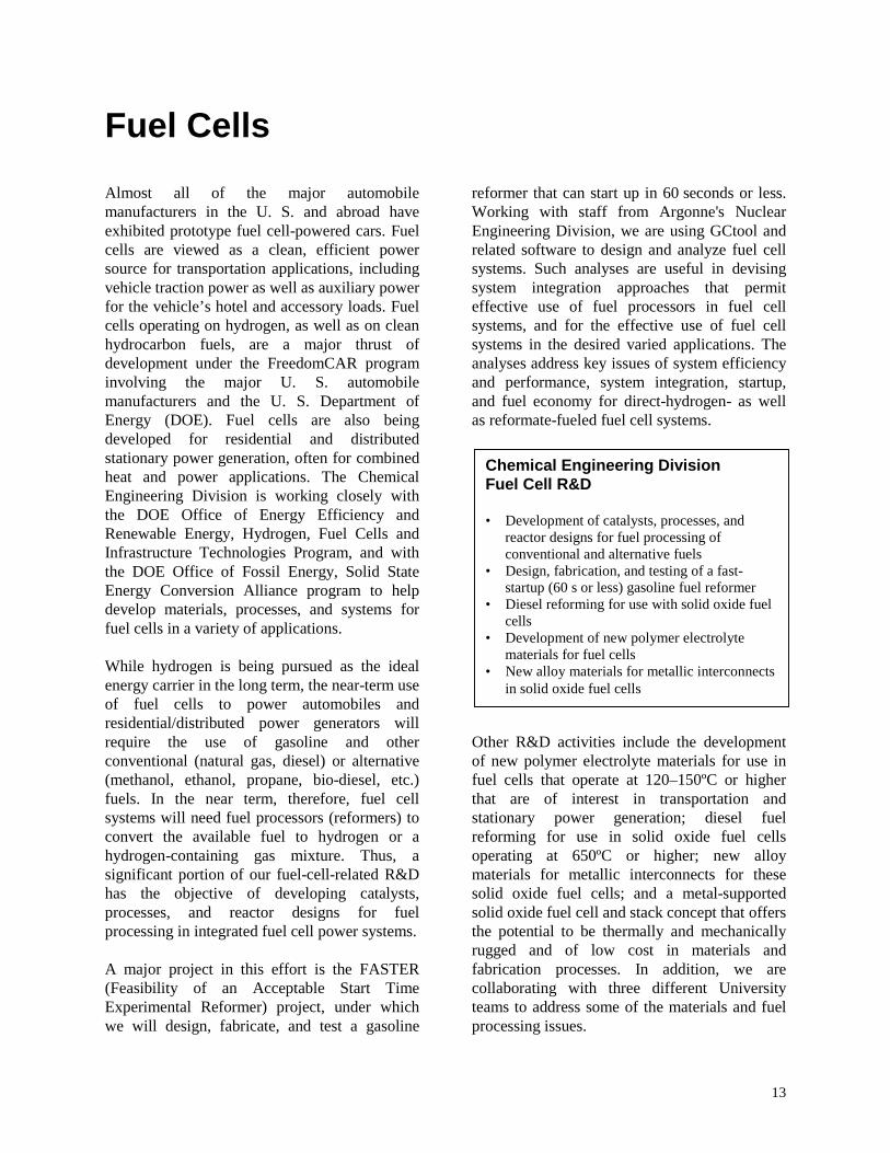
Chemical Engineering DivisionFuel Cell R&D
• Development of catalysts, processes, andreactor designs for fuel processing ofconventional and alternative fuels
• Design, fabrication, and testing of a fast-startup (60 s or less) gasoline fuel reformer
• Diesel reforming for use with solid oxide fuelcells
• Development of new polymer electrolytematerials for fuel cells
• New alloy materials for metallic interconnectsin solid oxide fuel cells
Fuel Cells
Almost all of the major automobilemanufacturers in the U. S. and abroad haveexhibited prototype fuel cell-powered cars. Fuelcells are viewed as a clean, efficient powersource for transportation applications, includingvehicle traction power as well as auxiliary powerfor the vehicle’s hotel and accessory loads. Fuelcells operating on hydrogen, as well as on cleanhydrocarbon fuels, are a major thrust ofdevelopment under the FreedomCAR programinvolving the major U. S. automobilemanufacturers and the U. S. Department ofEnergy (DOE). Fuel cells are also beingdeveloped for residential and distributedstationary power generation, often for combinedheat and power applications. The ChemicalEngineering Division is working closely withthe DOE Office of Energy Efficiency andRenewable Energy, Hydrogen, Fuel Cells andInfrastructure Technologies Program, and withthe DOE Office of Fossil Energy, Solid StateEnergy Conversion Alliance program to helpdevelop materials, processes, and systems forfuel cells in a variety of applications.
While hydrogen is being pursued as the idealenergy carrier in the long term, the near-term useof fuel cells to power automobiles andresidential/distributed power generators willrequire the use of gasoline and otherconventional (natural gas, diesel) or alternative(methanol, ethanol, propane, bio-diesel, etc.)fuels. In the near term, therefore, fuel cellsystems will need fuel processors (reformers) toconvert the available fuel to hydrogen or ahydrogen-containing gas mixture. Thus, asignificant portion of our fuel-cell-related R&Dhas the objective of developing catalysts,processes, and reactor designs for fuelprocessing in integrated fuel cell power systems.
A major project in this effort is the FASTER(Feasibility of an Acceptable Start TimeExperimental Reformer) project, under whichwe will design, fabricate, and test a gasoline
reformer that can start up in 60 seconds or less.Working with staff from Argonne's NuclearEngineering Division, we are using GCtool andrelated software to design and analyze fuel cellsystems. Such analyses are useful in devisingsystem integration approaches that permiteffective use of fuel processors in fuel cellsystems, and for the effective use of fuel cellsystems in the desired varied applications. Theanalyses address key issues of system efficiencyand performance, system integration, startup,and fuel economy for direct-hydrogen- as wellas reformate-fueled fuel cell systems.
Other R&D activities include the developmentof new polymer electrolyte materials for use infuel cells that operate at 120–150ºC or higherthat are of interest in transportation andstationary power generation; diesel fuelreforming for use in solid oxide fuel cellsoperating at 650ºC or higher; new alloymaterials for metallic interconnects for thesesolid oxide fuel cells; and a metal-supportedsolid oxide fuel cell and stack concept that offersthe potential to be thermally and mechanicallyrugged and of low cost in materials andfabrication processes. In addition, we arecollaborating with three different Universityteams to address some of the materials and fuelprocessing issues.

14
For More Information
Romesh Kumar, HeadFuel Cell DepartmentChemical Engineering DivisionArgonne National Laboratory9700 S. Cass Ave., Argonne, IL 60439630-252-4342, FAX [email protected]://www.cmt.anl.gov/science-technology/fuelcells/

15
Fuel Processor Engineering
Making the transition to hydrogen-powered fuel cells
Fuel-cell-powered vehicles will require ahydrogen-refueling infrastructure and on-boardhydrogen storage capacities that can offerdriving ranges comparable to those availablewith today’s gasoline-fueled internal combustionengine cars. The transition to the hydrogeninfrastructure can be bridged with the use of on-board fuel processors that can convert availablefuels (such as gasoline) to hydrogen. Thedemanding requirements of the automotiveapplication, together with the sensitive nature ofthe polymer electrolyte fuel cell, contribute to afuel processor design that is complex.
The Chemical Engineering Division hasdeveloped technologies and designs for on-boardfuel processors. A key requirement for these on-board fuel processors is their rapid startcapability. The U.S. Department of Energy(DOE) has targeted start-up times of 60 secondsfor the year 2005, and 30 seconds by 2010 atnormal ambient temperatures. Reducing thelarge thermal mass of the fuel processor, most ofwhich must be heated to several hundred degreesCelsius, will enable rapid start and also reducethe energy (fuel) consumed during startup.
2003 Research Highlights
Feasibility of Acceptable Start-TimeExperimental Reformer (FASTER): We areleading a collaborative program to design,fabricate, and demonstrate rapid start-up of alaboratory-scale (10-kWe, ~30-kWt) fuelprocessor. Contributing organizations includeLos Alamos (LANL), Oak Ridge (ORNL), andPacific Northwest (PNNL) NationalLaboratories and several universities and privateorganizations.
The FASTER design (Fig. 1) consists of anautothermal reformer (ATR) followed by a4-stage water-gas shift (WGS) reactor and a3-stage preferential oxidation (PrOx) reactor.Reformate temperatures are maintained atdesired levels with the help of six heatexchangers. Water injected before the fourthWGS stage helps cool the reformate and favorCO conversion in WGS4. HE1, the heatexchanger between the ATR and WGS1, is amicrochannel heat exchanger designed andfabricated by PNNL. The five other heatexchangers are of carbon foam construction,designed and fabricated by ORNL. Thepreferential oxidation reactors are designed andfabricated by LANL.
AT
R
WG
S1
WG
S2
WG
S3
WG
S4
P1 P2 P3
HE
2
HE
1
HE
3
HE
4
HE
5
HE
6
ATR Water
ATR Air
Start-up Air
Quench Water
PrOx Air
FuelReformateA
TR
WG
S1
WG
S2
WG
S3
WG
S4
P1 P2 P3
HE
2
HE
1
HE
3
HE
4
HE
5
HE
6
ATR Water
ATR Air
Start-up Air
Quench Water
PrOx Air
FuelReformate
Fig. 1. FASTER consists of a sequence of reactors and heat exchangers providedby the various project team members.

16
The FASTER startup strategy relies on the ATRcomponent reaching its operating temperaturevery quickly. This is achieved by operating at ahigh O/C [ratio of oxygen (from air) to carbon inthe fuel] ratio. The resulting reformate, whichcontains combustible gases (H2, CO, and lighthydrocarbons) will be oxidized just ahead ofWGS1, WGS2, and WGS3 by injectingcontrolled amounts of air. For initial productionof fuel-cell-quality fuel gas, only the ATR andthe first three zones of the shift reactor must bebrought up to temperature. The PrOx units havebeen sized to compensate for the higher CO (upto 4%) from the shift reactor during startup.
Readying the ATR to produce combustible gasesrequires rapid heating of the front edge of theATR catalyst. Figure 2 shows that with a 400-Welectric heating coil placed just ahead of thecatalyst, it took ~66 seconds to heat the catalystinlet face to 300°C. Introducing the fuel and airmixture onto the catalyst surface at that timeinitiated the oxidation reactions, which led to arapid rise in catalyst temperature.
0
200
400
600
800
1000
0:00 0:15 0:30 0:45 1:00 1:15 1:30Time, min:sec
Tem
per
atu
re, °
C
Igniter
CatalystInlet
121503-Test 06
Fuel/Air Started
Fig. 2. With a 400-W [1/16-in dia. heater rod]electric “igniter,” the inlet edge of the ATRcatalyst reached the light-off temperature of300ºC in 66 s.
Start-up can be accelerated if the power to theheater can be increased. A commerciallyavailable heater element (www.emitec.com)rated for higher power input, could be heated to
500°C in 10 seconds, by applying 1.6 kW ofelectric power (Fig. 3). Adapting such anelement for the ATR process has the potential toaccelerate ATR readiness. Similarly, the abilityto inject vaporized fuel will lower the catalysttemperature at which the fuel/air mixture can beinjected. These and other options are beinginvestigated to further accelerate start-up.
0
100
200
300
400
500
600
700
0 5 10 15 20Time, seconds
Tem
per
atu
re, °
C
0
100
200
300
400
500
600
700
0 5 10 15 20Time, seconds
Tem
per
atu
re, °
C
Fig. 3. A commercial electric heater can achievesurface temperatures of 500ºC and higher inabout 10 s using an input power of 1.6 kW.
FASTER components have been received fromsuppliers and are being integrated into the fuelprocessor containment vessel. Experimental datagenerated from the operation will be used tovalidate models and project fuel processordesigns that can meet constraints such as size,weight, start-up time, and fuel consumption forautomotive gasoline fuel processors.
This research is funded by the U. S. Departmentof Energy, Office of Energy Efficiency andRenewable Energy, Hydrogen, Fuel Cells, andInfrastructure Technologies Program.
Research Participants
Shabbir Ahmed, Daniel V. Applegate, SheldonH. D. Lee, Hsiu-Kai Liao, D. Dennis Papadias,Steven G. Calderone, Todd L. Harvey, AkramHossain, Rajesh Ahluwalia (NuclearEngineering Division), and Steven A. Lottes(Energy Systems Division). For moreinformation, please contact Shabbir Ahmed(630-252-4553, [email protected]).

17
Fuel Processor Catalysis
Catalysts to enable fuel cells to operate on today’s fuels
Reforming of gasoline, natural gas, and otherconventional or alternative fuels is one optionbeing pursued for supplying hydrogen forautomotive and stationary polymer electrolytefuel cell (PFEC) systems. Reforming involvesreacting the fuel with oxygen, generally suppliedas air, and water in the presence of a catalyst at600–1000°C to produce a hydrogen-rich gas,referred to as reformate. In addition to hydrogen,reformate contains significant amounts ofnitrogen, carbon dioxide, and carbon monoxide.Nitrogen and carbon dioxide do not affect theanode catalyst in the fuel cell stack; however,carbon monoxide “poisons” the anode catalystand degrades the performance of the fuel cell.To maintain an acceptable level of performance,the concentration of carbon monoxide inthe reformate must be reduced to <10 ppm.Two reactions, the water-gas shift(CO + H2O CO2 + H2) and preferential COoxidation (CO + ½O2 → CO2), are used toreduce the concentration of carbon monoxide toacceptable levels. Collectively, the catalystsused for the reforming, water-gas shift, andpreferential CO oxidation reactions are referredto as fuel processing catalysts. Availablecommercial catalysts are not suitable for useunder the demanding operating conditions inautomotive or small-scale residential fuel cellpower systems. Our research is focused ondeveloping new reforming and water-gas shiftcatalysts specifically tailored for use in theseemerging fuel cell applications.
2003 Research Highlights
Autothermal Reforming Catalysis: A primaryfocus of our research is to develop catalysts thatare not poisoned by the sulfur present inconventional fuels. For example, even after newregulations take effect in 2006, the averagesulfur content of gasoline would still be 30 ppmby weight (compared with 150 ppm in 1999).The sulfur content of natural gas is
approximately 30 ppm by volume. At theselevels, sulfur severely poisons the Ni-basedsteam reforming catalysts used in the industrialproduction of hydrogen. Typically, sulfurpoisoning occurs due to the adsorption of sulfuron, and the consequent blocking of, thecatalytically active sites. The extent of surfacecoverage by sulfur decreases with increasingtemperature. Thus, higher reaction temperaturespromote sulfur tolerance. This requires,however, that the catalyst be thermally stable atthese higher reaction temperatures.
We have developed a reforming catalyst basedon Rh dispersed on a lanthanum-modifiedalumina substrate that has been shown to exhibithigh fuel conversion, high selectivity forhydrogen, and low hydrocarbon breakthroughwhen reforming a variety of hydrocarbon fuels.As shown in Figure 1, this catalyst produced areformate containing 60 vol% H2 (dry, N2-freebasis) from a sulfur-free (<450 ppb S) gasolineat 700°C over a period of 100 h on stream. Withgasoline containing 34 ppm sulfur, the catalystseverely deactivated at 700°C with the H2
0
20
40
60
80
0 2 0 4 0 6 0 8 0 10 0T im e , h
H2
conc
entra
tion,
vol
% (d
ry, N
N2 -
free)
3 4 p pm S ga so line @ 800 o C
3 4 p p m S g a so lin e @ 70 0 C
S u lfu r-free g aso lin e @ 70 0 o C
o
Fig. 1. The rhodium-lanthanum-alumina auto-thermal reforming catalyst is resistant topoisoning by sulfur at 800ºC for the reformingof gasoline for automotive fuel cell systems.

18
concentration in the reformate decreasing fromits initial value of 60 to 18 vol% after 100 hourson stream. By increasing the reactiontemperature to 800°C, however, only a slightdecrease in the H2 concentration was observedduring first 20 h, with the H2 concentrationremaining steady over the next 80 h. We arecontinuing these tests to verify long-term(>1000 h) stability of this catalyst with sulfur-containing fuels.
Water-Gas Shift Catalysis: We are developingwater-gas shift catalysts that do not exhibit theloss in performance observed with commercialiron-chromium and copper-zinc oxide shiftcatalysts when used in fuel cell systems due tothe rapid startups, frequent shutdown/startupcycles, and frequent and rapid power variationsexperienced during normal operation. Our newshift catalysts are based on platinum (Pt)dispersed on a reducible cerium oxide substrate.These catalysts are more stable than thecommercial catalysts, but their cost is a majorconcern. We are attempting to reduce the costsof these catalysts by increasing their shiftactivity without increasing the platinum loading.
Our kinetic studies, as well as studies by otherresearch groups, suggest that the shift activity ofPt-ceria catalysts can be improved by increasingthe rate of dissociation of water, which is therate-controlling elementary reaction step in thecatalyzed water-gas shift reaction. For thispurpose, we are investigating the addition ofrhenium (Re) in the Pt-ceria catalyst. As shownin Figure 2, the addition of Re to Pt increases therate of CO conversion per gram of catalyst by
0.0E+00
1.0E-04
2.0E-04
3.0E-04
4.0E-04
5.0E-04
6.0E-04
200 250 300 350 400 450 500
Temperature, °C
CO
con
vers
ion,
(mol
CO
/g cat
-s)
1.81%Pt - 1.77%Re
0.87%Pt
0.91%Pt - 0.95%Re
2.86%Pt
Fig. 2. The Pt-Re catalyst is 2.5 times as active as thePt alone catalyst for the water-gas shiftreaction at temperatures of 300ºC or higher.
more than a factor of two with equivalent Ptloading at temperatures of 300°C or higher. Ourcurrent effort is focused on evaluating the long-term stability of these binary catalysts, for whichwe are conducting characterization studies todetermine the nature of the interaction betweenPt and Re.
This research is funded by the U.S. Departmentof Energy, Office of Energy Efficiency andRenewable Energy, Hydrogen, Fuel Cells, andInfrastructure Technologies Program.
Research Participants
Theodore R. Krause, Jennifer R. Mawdsley,James M. Ralph, Sara Yu Choung, Magali S.Ferrandon, and Razima Souleimanova. Formore information, contact Theodore Krause(630-252-4356, [email protected]).

19
Fuel Cell Systems Analysis
Finding the right balance of efficiency, cost, and performance for automotive use
While different developers are addressingimprovements in individual components andsubsystems in automotive fuel cell propulsionsystems (e.g., cells, stacks, fuel processors,balance-of-plant components), we are usingmodeling and analysis to address issues ofthermal and water management, design-pointand part-load operation, and component-,system-, and vehicle-level efficiencies and fueleconomies. Such analyses are essential foreffective system integration. We use Argonne’sGCtool software package to devise and analyzesystem configurations, performance, efficiency,and fuel economy.
2003 Research Highlights
We have analyzed conceptual pressurized directhydrogen fuel cell systems (FCS) for a hybridmid-size SUV. In such systems, the FCS alonemust be able to meet the vehicle’s powerdemand under all sustained driving conditions,such as 100 mph on a level road, or 55 mph on a6.5% grade. In addition, the vehicle must be ableto accelerate from zero to 60 mph in 10 s, usingbattery assist if needed.
We analyzed three systems with different levelsof hybridization (i.e., fuel cell power versusbattery power) to meet these requirements.Table 1 lists the significant attributes of the threesystems. The sustained top speed necessitates aminimum fuel cell power of 80 kW. FCS-1 is a100-kW system with only a compressor, noexpander; FCS-2 is 100-kW system with acompressor/expander/motor module (CEM); andFCS-3 is a 160-kW system with a CEM.Without the expander to recover the energy inthe pressurized exhaust, the compressor inFCS-1 needs a rather large 27-kW motor. Withthe expander in FCS-2, the CEM motor power isonly one-third that of the motor in FCS-1. BothFCS-1 and FCS-2 require battery assist to meetthe 0-60-mph acceleration requirement. FCS-3 is
Table 1. Vehicle/fuel cell system parameters for the hybrid mid-size SUV
Mid-Size All Wheel Drive SUVGross Vehicle Wt, kg 2400Frontal Area, m2 2.46Rolling Friction Coeff. 0.0084Drag Coefficient 0.41Traction Power, kWe: 0–60 mph in 10 s 100 mph, level 55 mph, 6.5% grade
1608070
Fuel Cell SystemsFCS-1 FCS-2 FCS-3
Rated Power, kWe 100 100 160Comp/Exp/Motor w/o Exp w/ Exp w/ ExpCEM Power, kWe 27.3 9.5 15.1System Efficiency, %, @ Rated Power @ 80 kWe @ 20 kWe
475262
545663
545964
large enough to power the SUV without abattery assist. At the rated power as well as atpart load, FCS-3 has the highest efficiency whileFCS-1 offers the lowest efficiency.
Stack Performance: Figure 1 shows theperformance of the stack in FCS-2 at cold(startup) and warm conditions. At 80ºC, thedesign operating temperature, the stackgenerates ~105 kWe and 0.7 V/cell at the ratedpower point. At a cold start from 20oC, thepower produced is 20% lower, along with alower cell voltage of 0.55 V. During startupfrom −20oC, the maximum stack power isreduced by 35% and the cell voltage is furtherlowered to 0.45 V. The lower cell voltages leadto proportionately lower fuel cell efficiencies.
Heat Rejection System: Our analyses show thatthe size of the heat rejection system for the SUVis determined by the performance requirementon a 6.5% grade, rather than the top sustainedspeed; a radiator sized for the heat duty at

20
Fig. 1. Fuel cell stack performance as a function oftemperature for the 100-kWe stack in FCS-2.The available power is reduced by 20–35%during cold starts.
55 mph on a 6.5% grade can meet the systems’heat rejection requirements at all speeds.Further, in the case of the FCS-3, no heatrejection is needed at speeds of less than60 mph, indicating that the fuel cell stack cannotbe maintained at 80oC at low speeds. The trendfor the radiator heat duty is similar for FCS-2,but the maximum heat load is nearly twice aslarge, even though the fuel cell system is almost40% smaller. Unlike the radiator, however, thecondenser for the 100-kW system is smaller thanthe one for the 160-kW system.
CEM Idle Speed: We also examined the airmanagement system for issues of idle speed andmaximum turndown. The CEM plays animportant role in determining the transientresponse, cold start-up, and part-loadperformance of a pressurized FC system. For ahigh-speed, matched, turbo compressor/expander module, we found that with anexpander the maximum turndown can be as highas 20; without an expander, however, themaximum allowable turndown may be nogreater than about 5.
Fuel Cell System Efficiency: The systemefficiency at part load and the dynamicfluctuations in efficiency during a drive cycledepend on the maximum CEM turndown and thepresence or absence of an expander in thesystem. Figure 2 shows the effect of CEM
turndown on the efficiency of FCS-2 when thevehicle is driven on the Federal Urban DrivingSchedule (FUDS). Differences in efficiency areevident at low loads for maximum CEMturndowns of 5 and 20, respectively. Both giveefficiencies in excess of 60% on FUDS, but witha turndown of 20, the peak efficiency can exceed70% at low loads. The scatter in dynamicefficiency is largely due to acceleration demandsfrom idling speeds. Figure 2 also shows thecontribution of the expander to systemefficiency. Differences in efficiency at highloads are due to the significant power generatedby the expander; at low loads, the significantdifferences in efficiency are due to the higherturndown available with an expander in thesystem.
0.0
0.1
0.2
0.3
0.4
0.5
0.6
0.7
0.8
0 10 20 30 40 50 60 70
FC System Power, kW
FC
Sys
tem
Effi
cien
cyWith Expander, Turndown = 20
Without Expander, Turndown = 5
100 kW FCS, Warm Start
With Expander, Turndown = 5
Fig. 2. The pressurized direct hydrogen fuel cellsystems offer efficiencies of >60% at partloads. The dynamic efficiencies can besignificantly lower, particularly with systemswithout an expander.
This research is funded by the U.S. Departmentof Energy, Office of Energy Efficiency andRenewable Energy, Hydrogen, Fuel Cells, andInfrastructure Technologies Program.
Research Participants
Romesh Kumar, Rajesh Ahluwalia (NuclearEnergy Division, NE), E. Danial Doss (NE), andXiaohua Wang (NE). For more information,contact Romesh Kumar (630-252-4342,[email protected])
0.0
0.1
0.2
0.3
0.4
0.5
0.6
0.7
0.8
0.9
1.0
0.0 0.1 0.2 0.3 0.4 0.5 0.6 0.7 0.8Current Density (A/cm 2 )
Vol
tage
(V
)
0
15
30
45
60
75
90
105
120
135
150
Sta
ck P
ower
(kW
)
80oC
20oC
-20oC
100 kW FCS O2 Utilization = 50%Turndown = 20

21
Hydrogen and Fuel Cell Materials
Materials development to enable commercialization
Fuel cell power systems have been demonstratedfor applications as varied as milliwatt-level cellphones and kilowatt-level vehicle traction. Nowthat it has been demonstrated that fuel cellsystems can deliver the necessary power withimproved fuel efficiency, the technologydevelopment focus is on lowering cost,improving durability, and reducing system sizeand weight. Materials advances are needed inmany system components to achieve these goals.Research in the Chemical Engineering Divisionaims to address materials issues for polymerelectrolyte and solid oxide fuel cell systems toenable their widespread commercialization.
The state-of-the-art electrolyte for the polymerelectrolyte fuel cell, being developed for vehicletraction and residential power, requireshumidification to conduct protons and thus itsoperating temperature is limited to <100ºC(typically 80ºC). This requirement addscomplexity, size, weight, and cost to the fuel cellpower system. Argonne’s approach todeveloping membrane electrolytes with highproton conductivity at low relative humidity andtemperatures above 100ºC is to utilize sufonatedpolyaryl ether dendrimers (highly branchedmacromolecules). The polyaryl ether dendrimerswere chosen as the membrane building blocksbecause they have a high density of proton-conducting functional groups, are thermallystable, and are expected to be stable in the fuelcell environment.
Solid oxide fuel cells (SOFCs) are attractivepower sources for vehicular auxiliary powerapplications because they exhibit high powerdensities and efficiencies, have simplified fuelreforming requirements, and are fuel-flexible.These SOFC-based power systems are viewed asbeing ideal for auxiliary power units (APUs) forlight- and heavy-duty vehicles. The SOFCspresently being developed use the anode orelectrolyte as the cell support. We have
developed an SOFC design concept, TuffCell,that uses a metallic bipolar plate as the cell andstack support. The TuffCell offers an inherentlymore rugged design than the anode- orelectrolyte-supported designs, and the potentialfor much lower manufacturing costs.
2003 Research Highlights
Polymer Electrolyte Development: The highdensity of ionic groups on the dendrimerelectrolyte building blocks renders them solublein water, the product of the fuel cell reaction.Our approach to forming water-insolublemembranes is to cross-link the dendrimers orattach them to insoluble polymer backbones.Our efforts this year have been focused onsynthesizing significant quantities of thepolyaryl ether dendrimers up to generation four(four levels of branching), shown in Figure 1,and attaching them to water-insoluble polymerbackbones, such as polyepichlorohydrin.Thermal gravimetric analysis has shown thatmembranes formed by attaching the generationtwo dendrimer to polyepichlorohydrin arethermally stable up to 240ºC. Initialmeasurement of the proton conductivity of thismembrane showed a conductivity of 0.1 S/cm at
O
O
O
O
O
O
O
O
O
O
O
O
O
O
O
O
O O
O O OO
OO
O
O O
O
O
O
O
O
O
O
OO
O
O
O
O
O
O
O
O
O
O
OO
OOO
O
O
OO
OO
O
O
O
O
O
SO3H SO3H SO3H SO3H
SO3H
SO3H
SO3H
SO3H
SO3H
SO3H
SO3H
SO3H
SO3H
SO3H
SO3H
SO3H
HO3SHO3S
HO3SHO3S
HO3S
HO3S
HO3S
HO3S
HO3S
HO3S
HO3S
HO3S
HO3S
HO3S
HO3S
HO3S
O
O
O
O
O
O
O
O
O
O
O
O
O
O
O
O
O O
O O OO
OO
O
O O
O
O
O
O
O
O
O
OO
O
O
O
O
O
O
O
O
O
O
OO
OOO
O
O
OO
OO
O
O
O
O
O
SO3H SO3H SO3H SO3H
SO3H
SO3H
SO3H
SO3H
SO3H
SO3H
SO3H
SO3H
SO3H
SO3H
SO3H
SO3H
HO3SHO3S
HO3SHO3S
HO3S
HO3S
HO3S
HO3S
HO3S
HO3S
HO3S
HO3S
HO3S
HO3S
HO3S
HO3S
Fig. 1. A polyaryl ether dendrimer (generation 4shown here) is the building block of a newpolymer membrane electrolyte for fuel cells.

22
76ºC and 6% relative humidity, a conductivitycomparable to that of the currently usedcommercial polymer electrolyte under 100%relative humidity conditions. Measurements athigher temperature are underway.
The focus of future work will be on identifyingand synthesizing suitable cross-linkingmolecules. In addition we will investigate theeffects of dendrimer size, degree of cross-linkingand length of the cross-linking molecules onmembrane characteristics, including ionicconductivity, membrane morphology andthermal stability. The ultimate goal of thisproject is to develop a polymer with the requiredhigh proton conductivity (>0.1 S/cm) attemperatures up to 150ºC and low humidityconditions and to demonstrate this polymer in anoperating fuel cell.
Metallic Bipolar Plate-Supported Solid OxideFuel Cell (TuffCell): During 2003, we built andtested several cells of the TuffCell design(Fig. 2). TuffCell’s superior mechanicalproperties were proven in impact tests and infour-point bending tests that showed these cellsto have failure strengths four times higher thanthose of commercial anode-supported cells. Themaximum power density achieved with singlecells operating on hydrogen/air at 800°C wasincreased this year from 30 mW/cm² to morethan 250 mW/cm² (Fig. 3) through improve-ments in the cathode material and the anodestructure. This electrochemical performance wasnot degraded by several temperature cyclesbetween room temperature and 800°C at10°C/min.
In addition to improving the design andmaterials to increase power density, future workwill focus on increasing the individual cell size,building short stacks of cells, testing these stacksusing hydrogen and simulated reformate, anddetermining start-up time, ability to cycle the
Cathode (ceramic)
Electrolyte (ceramic) Anode (cermet)
Anode flow field (metal)
Interconnect (metal)
Cathode flow field (metal)
4 mm
Fig. 2. The TuffCell’s metallic bipolar plate serves asthe support for the ceramic cell components,making it mechanically and thermally robust.
0.0
0.2
0.4
0.6
0.8
1.0
1.2
0 100 200 300 400 500 6000.0
0.2
0.4
0.6
0.8
1.0
1.2
0 100 200 300 400 500 600 700 800 900Current Density (mA/cm2)
Cel
l Vo
ltag
e (V
)
0
50
100
150
200
250
300
350
Pow
er D
ensi
ty (
mW
/cm
2 )
Apr ’02
Aug ’02
Nov ’02
0.0
0.2
0.4
0.6
0.8
1.0
1.2
0 100 200 300 400 500 6000.0
0.2
0.4
0.6
0.8
1.0
1.2
0 100 200 300 400 500 600 700 800 900Current Density (mA/cm2)
Cel
l Vo
ltag
e (V
)
0
50
100
150
200
250
300
350
Pow
er D
ensi
ty (
mW
/cm
2 )
Apr ’02
Aug ’02
Nov ’02
Fig. 3. The maximum power density achieved withsingle TuffCells has been increased to>250 mW/cm² through improvements in thecathode material and the anode structure(800ºC, hydrogen/air).
temperature, and cell durability. The ultimategoal of this research is to develop rugged, high-power-density, low-cost stack units made by acommercially viable manufacturing process.
This research is funded by the U.S. Departmentof Energy, Office of Energy Efficiency andRenewable Energy, Hydrogen, Fuel Cells &Infrastructure Technologies Program.
Research Participants
Deborah J. Myers, Suhas G. Niyogi, Seong-WooChoi, J. David Carter, and James M. Ralph.For more information, contact Deborah Myers(630-252-4261, [email protected]).

23
Solid Oxide Fuel Cells
Finding new materials and catalysts to improve fuel cell performance
The Solid State Energy Conversion Alliance(SECA) is a U.S. Department of Energy (DOE)program aimed at developing fuel cell powermodules of 3-10 kW electrical capacity based onsolid oxide fuel cells. The Chemical EngineeringDivision is contributing to this program as aCore Technology participant, addressing threeissues of generic nature.
2003 Research Highlights
The Division is engaged in addressing threedistinct issues in solid oxide fuel cell develop-ment: (1) improving the corrosion resistance ofmetallic bipolar plates, (2) investigatingpoisoning of cathodes by chromium, and(3) exploring new sulfur-tolerant catalysts fordiesel fuel reforming. These three tasks are partof the Core Technology program of the SECAinitiative, whose objective is to develop modularSOFC systems of 5 kW capacity.
To improve the corrosion resistance of steels inthe SOFC environment, we are pursuing aninnovative technique of functionally grading thecomposition of the steels. Using a tape-castingtechnique, we can vary the composition fromone side of a plate to the other and enrichcomponents that have improved corrosionresistance on either the air or the fuel side.Figure 1 shows a cross section of a SS430 steelwith a substantial amount of lanthanum chromitein the surface. The latter offers protectionagainst oxidation by hot air and steam, as isencountered on the air side of the fuel cell. Thelanthanum chromite can be enriched in thesurface by tape-casting the powder together withstainless steel powder. Work is continuing tomake the lanthanum chromite layer dense.
Poisoning of cathodes by chromium has beennoticed by several groups developing planarsolid oxide fuel cells using ferritic stainlesssteels as interconnect materials. When testing
Fig 1. Stainless steel enriched with lanthanumchromite at the surface.
such cells, the cell potential declines within afew days by more than 20% and chromiumdeposits are found in the cathodes. Argonne wasasked by DOE to investigate the phenomenon.
We operated several cells with three differentsteels and two different cathode materials andconfirmed the observations of others. Figure 2shows the chromium content in a cathode thathad been operated for 250 hours at 700oC.Between 1 and 3.5 % chromium is found in thecathode, with higher concentrations near theelectrolyte where the electrochemical reactionsoccur. Clearly, chromium is lost from theinterconnect material and is being transportedthrough the cathode to the electrochemicallyactive area, where it interferes with the normalhydrogen oxidation reaction. We are nowworking on methods to prevent this migrationfrom occurring.
Small solid oxide fuel cell systems of about5 kW capacity are potentially applicable asauxiliary power units for heavy-duty vehiclessuch as tractor-trailer trucks. The diesel fuelused in these vehicles needs to be converted intoa hydrogen-rich gas before it can be used in thefuel cell. Catalysts for converting diesel fueldeactivate in less than 100 hours due to the high

24
Fig. 2. SEM of LSF Cathode having 430 SS Interconnect from SOFC (#14) at 700oC.
temperature and sulfur content of the fuel. TheDivision is exploring a new generation ofcatalysts that may overcome these problems.
In the past 12 months, we were able to show thatperovskites such as LaCrO3 and LaAlO3 whendoped on the B-site with certain elementsperform very well.
Figures 3 and 4 show the hydrogen yield permole of fuel that is obtained with the aluminiteand chromite catalysts. The catalysts performsimilarly and are as active as previously knownnoble-metal catalysts.
The observation of good reforming activity fromthe B-site doped aluminite is intriguing andunexpected. It is known that undoped alumina
0
5
10
15
20
25
0.3 0.4 0.5
O2/C
H2
yiel
d, (
H2-
mo
l/Fu
el-m
ol)
Aluminite Cat. Chromite Cat.
Fig. 3. Hydrogen yield during ATR reforming ofdodecane at different O2/C ratio overaluminite and benchmark chromite ATRcatalysts.
shows little POX or SR catalytic activity inhydrocarbon reforming, contrary to the case ofchromite. The oxidation state of Al+3 is also toostable under either reducing or oxidizingconditions to participate in any redox reaction.The catalytic activity is therefore related to theB-site dopant.
This research is funded by the U.S. Departmentof Energy, National Energy TechnologyLaboratory.
Research Participants
Michael Krumpelt, Terry A. Cruse, andDi-Jia Liu. For more information,contact Michael Krumpelt (630-252-8520,[email protected].
0
5
10
15
20
25
1.0 2.0 3.0
H2O/C
H2
yiel
d, (
H2-
mo
l/F
uel
-mo
l)
Aluminite Cat. Chromite Cat
Fig. 4. Hydrogen yield during ATR reforming ofdodecane at different H2O/C ratio overaluminite and benchmark chromite ATRcatalysts.
012345678910
05101520
Distance from electrolyte, micron
Cr
Lev
el, w
t%

25
Fuel Cell Testing and Evaluation
Providing standardized, independent analyses for fuel cell developers
Fuel cell developers, fuel cell users, automakers,and government and private agencies all needsome way to obtain an unbiased assessment ofthe fuel cell technologies currently beingdeveloped for transportation. Argonne NationalLaboratory’s Fuel Cell Testing Facility can meetthat need, providing independent, standardizedtesting and evaluation.
The Facility draws on Argonne’s extensiveexperience evaluating batteries and battery testequipment, and provides the same high-qualitytesting for fuel cells. Equipped with extensiveand specialized hardware and computing power,the Facility is ideally suited to the complex taskof testing fuel cell systems, including how wellfuel cell stacks and supporting componentsinteract. The Facility provides a standard testenvironment for benchmarking new fuel cellstacks and systems. Since the evaluations areindependent as well as standardized, the testresults help validate the capabilities of aparticular fuel cell technology and allow for itsdirect comparison with competing fuel celltechnologies.
Designed to AutomotivePower Criteria
The Fuel Cell Test Facility has been specificallydesigned to automotive power criteria. It isequipped to test fuel cell stacks and systems upto 80 kW, the size needed for a passenger car.
The brain of the facility is a computer-controlledelectronic load system that can simulate thepower demands of a vehicle. The heart of thefacility is a sophisticated gas managementsystem that supplies air and fuel to the fuel cell
with precise control of flow rate, pressure,temperature, and humidity and can simulate therapid gas-flow changes found in actual drivingconditions, as cars accelerate and brake. The fuelcan be hydrogen, gasoline or simulatedreformate. (Reformate is the output gas of adevice that produces hydrogen from other fuels,such as methanol, gasoline, or natural gas.)
Most recently, Argonne’s Fuel Cell Test Facilityhas begun testing fully integrated fuel cellsystems that incorporate their own fuelprocessing and air supply subsystems. In ourfuel cell work, we have evaluated stacks andcomplete systems from many developers. Theseranged from 0.72-kW stacks (hydrogen-fueled)to a 50-kW complete system (gasoline-fueled).We have also evaluated a partial fuel cell systemconsisting of the complete system minus the fuelcell stack.
The Fuel Cell Test Facility is part of theElectrochemical Analysis and DiagnosticsLaboratory (EADL). The EADL was establishedby the U.S. Department of Energy (DOE),Office of Energy Efficiency and RenewableEnergy, FreedomCAR and VehicleTechnologies Office. The FCTF was establishedby DOE’s Office of Hydrogen, Fuel Cells andInfrastructure Technologies.
Research Participants
Ira D. Bloom, Daniel J. Andrekus, Scott A.Jones, Edward G. Polzin, and Benjamin G.Potter. For more information, contact Ira Bloom(630-252-4516, [email protected]). Visit ourweb site at http://www.cmt.anl.gov/facilities/eadl.shtml.

26

27
Fuel Cell Technical Analysis
Supporting U.S. Department of Energy research and development
Argonne’s Chemical Engineering Division (theDivision) provides technical and programmaticanalysis for the U.S. Department of Energy,Hydrogen, Fuel Cells, and InfrastructureTechnologies, and FreedomCAR and VehicleTechnologies Programs. In this capacity,Division technical experts participate in reviewsto evaluate contractor progress, provide feed-back to DOE and its contractors, prepare inputfor program plans and work statements, organizetechnical workshops, and evaluate the technicalmerit of proposals. Representative activitiescarried out in 2003 are described below.
2003 Highlights
Non-platinum electrocatalyst workshop:Platinum group metal (PGM) electrocatalysts arecurrently used on the polymer electrolytemembrane (PEM) fuel cell anode and cathode tofacilitate electrochemical reactions (hydrogenoxidation and oxygen reduction, respectively).The use of these catalysts contributessignificantly to the overall cost of the fuel cellstack as well as to the overall system cost. Thereis also some concern about future productioncapability, reserves, and cost of thesePGM catalysts. Hence, there is national interestin the development and use of non-PGMcatalysts in the PEM fuel cell, particularly on thecathode side. The Division helped to organizea Non-Platinum Electrocatalyst Workshopin March 2003 (see http://www.eere.energy.gov/hydrogenandfuelcells/electrocatalysts_workshop.html) to discuss approaches to developingelectrocatalysts that do not contain PGMs.Sessions on inorganic and organic approacheswere held. Participants included representativesof industry, academia, and DOE nationallaboratories.
Fuel cells for stationary and automotiveapplications: Division personnel assisted indrafting the Statement of Work in a DOE
solicitation “Research and Development of FuelCells for Stationary and AutomotiveApplications.” The solicitation covered a widerange of topics, including the development anddemonstration of stationary fuel cells forbuilding and back-up/peak shaving applications,the development of natural gas fuel processingsystems, the development of improved stack andsystem components, the development ofplatinum recycling technology and non-preciousmetal catalysts, and the economic analysis ofPEM fuel cell systems. We participated in theproposal review process and advised DOEduring the proposal selection process. Thesolicitation resulted in the selection of 13 firmsand educational institutions in 12 states toreceive $75 million in cost-shared awards tofund new research in advanced fuel celltechnology for vehicles, buildings and otherapplications
Portable and off-road fuel cell powerapplications: Division staff drafted a Statementof Work for the DOE solicitation “Research,Development, and Integration of Energy-Efficient Technologies in Portable Power,Auxiliary Power Units, and Offroad Fuel CellApplications.” The solicitation addressedportable fuel cells for low-power (sub-watt to20- to 50-W) applications such as consumerelectronics and high-power (1- to 10-kW)applications such as auxiliary power units(APUs) for hotel and refrigeration loads forlong-haul trucks and recreational vehicles. Thepurpose of the research is to demonstrate themarket readiness of the proposed consumerelectronics or auxiliary power unit fuel cellsystems and to help expedite the commercialintroduction of fuel cells. The solicitation wasissued in 2003, and the Technical AnalysisGroup reviewed proposals and served astechnical support for the Source EvaluationBoard. Announcement of awards is expected in2004.

28
On-board fuel processing decision: Thetransition to a hydrogen economy will takedecades. During this transition, technologies thatuse the current liquid and gaseous fuelinginfrastructure will be needed to provide thehydrogen to power fuel cell vehicles. Manyoptions are being considered, such as fuelreforming on-site at fueling stations or fuelreforming on-board the vehicle. Truly renewablesources of hydrogen are the long-term goal. TheDOE has funded R&D of on-board fuel-flexiblereforming technologies for the past 10 years.Based on the current state of technologydevelopment, it is uncertain that on-board fuelprocessing technologies will meet the technicalcriteria (start-up/transient time, energyconsumption, durability, and cost) by 2010 tosupport the hydrogen transition phase. Divisionrepresentatives are actively engaged in DOE’sanalysis of the prospects for successfulattainment of the goals and the decision tocontinue R&D in this area.
Compressor/expander/motors: DOE continuesto evaluate compressor/expander/motor andmotor controller (CEMM) devices for fuel cells.Division experts are actively engaged indefinition of key operating parameters andquanitification of performance goals as well astechnical management of the followingprograms. Development is underway at UTCFuel Cells, Honeywell Engines and Systems,and Mechanology, Inc. UTC’s blowers (for air
delivery to the fuel cell as well as to the fuelreformer) for a 50- to 75-kWe fuel cell have beenfabricated and will be tested by ArgonneNational Laboratory (at the compressor teststand that is located at Mechanology, Inc., inAttleboro, Massachusetts). Mechanology’s testrig is one of the few in the nation that has thecapability to independently run such devices.Mechanology is allowing Argonne no-costprivate access, following familiarization with thetest stand, to conduct the acceptance tests forDOE.
Fuel cell codes and standards: The Divisionactively participates in the Society ofAutomotive Engineers (SAE) Fuel CellStandards Committee that is developingrecommended practice guides and standards forfuel cell vehicles in the following areas: safety,performance, fueling interface, emissions andfuel economy measurement, and recyclability.The SAE activity is coordinated with othernational and international standards-settingorganizations.
Participants
Walter F. Podolski, Thomas G. Benjamin,Brian T. Concannon, Robert D. Sutton, andWilliam M. Swift. For more information,contact Walter Podolski (630-252-7558,[email protected]).

29
Process Chemistry and Engineering
The Chemical Engineering Division (theDivision) conducts research on the treatment anddisposal of nuclear wastes generated atDepartment of Energy (DOE) sites and bycommercial light water reactors. Our researchfalls into two primary areas: (1) methods ofseparating wastes for further treatment to reduceoverall toxicity, fissile content and volume, and(2) the behavior of waste materials followingtheir disposal in the proposed Yucca Mountainrepository
Waste Separation
Our work focuses on (1) developing separationtechnologies for the safer long-term disposal ofspent nuclear fuel in support of the AdvancedFuel Cycle Initiative (AFCI), (2) the use of low-enriched-uranium (LEU) in the production of99Mo, and (3) providing research anddevelopment support for the Savannah RiverSite (SRS) Salt Processing Project.
Separation technologies for safer long-termdisposal of spent nuclear fuel – UREX+ processdemonstration: Research under the DOE’s AFCIprogram is developing safer alternatives to thelong-term disposal of spent nuclear fuel toimprove the performance of the geologicalrepository. Current strategy focuses on spentfuel separation into five streams: (1) a uraniumproduct stream that will be solidified anddisposed of as low-level waste, (2) a technetiumproduct that will be transmutated, (3) anelectrical power generator TRU product stream,consisting of a Pu/Np product that will beconverted to mixed oxide fuel and Am/Cmproduct that will be transmutated by fissioning,(4) a cesium and strontium product for interimdecay storage, and (5) a long-lived fissionproduct that will be incorporated in superiorwaste forms for disposal in a geologicalrepository. The UREX+ process consists of fivesolvent extraction processes. The entire processwas demonstrated in 2003 with a hot simulant
and actual dissolved spent fuel. Excluding theeffects of process upsets, product specificationswere met for disposal of uranium as non-transuranic low-level waste, technetium fissilecontent, Pu/Np mixed oxide fuel fabricationconcentration requirements, and interim storagerequirements for Cs/Sr product.
Use of Low-Enriched Uranium in 99MoProduction: Production of medical-grade 99Moby thermal neutron fission of 235U, generally inhigh-enriched-uranium (HEU) targets, accountsfor a significant fraction of U.S. HEU exports.99Tc, the daughter of 99Mo, is the mostcommonly used medical radioisotope in theworld. The U.S. Reduced Enrichment forResearch and Test Reactors (RERTR) programis working to limit the use of HEU bysubstituting LEU fuel and targets, reducingproliferation concerns. The substitution of LEUin targets requires approximately five timesmore total uranium, requiring modifications tothe target design and recovery/purification stepsnecessary. In 2003, we demonstrated processingsteps at the laboratory scale to improve theefficiency of the converted LEU process withArgentine Comisión Nacional de EnergíaAtómica (CNEA). A full scale demonstration isplanned in Argentina during 2004. Also wedeveloped two alternatives for the treatment ofuranium-rich acid waste for MDS Nordion inCanada and ANSTO in Australia by directcalcination and oxalate precipitation. Directcalcination generates primarily UO3 and NOx,while oxalate precipitation generates primarilyUO2 and CO2 products.
Research and development support for SRS SaltProcessing Project: Nearly 34 million gallons ofradioactive high-level waste (HLW) arecurrently stored in tanks at the Savannah RiverSite in South Carolina. Because of the high costassociated with disposal of the HLW, it isdesirable to reduce its volume. Divisionresearchers are developing a process to remove

30
Sr and TRU from tank waste using in-situ-formed mixed iron oxides (IS-MIO) that couldreplace the current baseline process, which usesmonosodium titanate (MST). This year’s studiesdemonstrated that the iron loading can bereduced with no penalty to the process and thatthe solids formed could be filtered by the currentbenchmark process.
Waste Form Behavior
DOE will submit a license application to theNuclear Regulatory Commission in December2004 to construct a geological repository at theYucca Mountain Site. We are developing theperformance assessment models for commercialspent nuclear fuel and defense high level waste(DHLW) glass. Our work also supports thequalification and long-term performanceassessment of ceramic and metal waste formsfrom the electrometallurgical treatment of spentsodium-bonded Experimental Breeder Reactor-IIfuel.
Spent Fuel from Commercial Reactors andDHLW Glass for the Yucca Mountain Project:We have been selected to develop models tocalculate the degradation and radionucliderelease rates from the commercial spent fuel andDHLW glass for performance assessment. Tosupport the modeling effort, we have conductedtests under a range of environmental conditions,including repository-relevant unsaturatedconditions. Tests conducted in humid air haverecently shown that deliquescent salts in thewaste can have important effects. The fissionproduct inventory of deliquescent fissionproduct salts (e.g., CsI) in the fuel/cladding gapregion may promote condensation of water andcause aggressive conditions that break down thepassive film and promote active corrosion of thefuel and cladding. Experimental work hasidentified waste form reactions and estimatedtheir rates for long disposal times, anddemonstrated the role of alteration products insequestering radionuclides. We have also shownhow x-ray absorption spectroscopy can be usedto characterize the crystal chemistry of traceelements in spent fuel and its alteration products.
EBR-II Waste Forms: Spent sodium-bonded fuelmust be treated prior to disposal in the wasterepository. Two waste forms will be used toimmobilize wastes from electro-metallurgicallytreated fuels for disposal: a ceramic waste form(CWF) will be used to immobilize radioactivesalts and a metallic waste form (MWF) will beused to immobilize contaminated cladding hulls.Laboratory tests are being conducted to addressqualification requirements with regard to boththe waste forms and their impact on the disposalsystem.
Spinoff Research: Human-Detoxification System
We are developing a human-detoxificationsystem based on biocompatible and injectablenanospheres as a novel portable method ofprotecting people from acute exposures tobiological, chemical or radiological toxins.Specific toxins or pathogens can be removedfrom the blood circulation by functionalizedmagnetic nanoparticles. These particles are thenremoved from the body using a magneticfiltration system. The focus of the initialinvestigation is on (1) nanoparticle development,(2) filtration system design and (3) testing of aprototype system in animal models. Theimportance of encapsulated oils in themicrospheres as a way to increase magneticnanophase loading and avoid clustering has beenidentified and specialized polymers have beensynthesized that allow direct binding to thereceptors. A prototype magnetic separator tostudy separation of magnetic nanospheres inblood was constructed and in vivo studies of thepharmocokinetics of the system were initiated.
For More Information
Monica C. Regalbuto, HeadProcess Chemistry and Engineering DepartmentChemical Engineering DivisionArgonne National Laboratory9700 S. Cass Ave.Argonne, IL 60439630-252-1540, fax [email protected]/science-technology/processchem/

31
UREX+ Process Demonstration
Improved separations lead to safer long-term disposal of spent nuclear fuel
The safe and economical disposal of spent fuelfrom commercial nuclear reactors will help toensure a stable energy supply for the future. Ascurrently envisioned, this spent fuel will beplaced directly into a geologic repository.However, if key radionuclides present in thespent fuel can be sufficiently separated from theremaining components, the volume, toxicity, andfissile content of spent fuel now requiringrepository disposal can be reduced. Uranium, themajor component by volume can potentially bedisposed as low-level waste. Long-livedtransuranic elements can be transmuted innuclear reactors, while short-lived but highlyradioactive elements can be isolated and allowedto decay prior to permanent disposal. The endresult would be a safer, simpler geologicrepository and would avoid the need for asecond repository. New processes can alsoreduce the risk of proliferation associated withcomponents of spent fuel.
The U.S. Department of Energy’s AdvancedFuel Cycle Initiative (AFCI) Program is tryingto achieve these goals by separating dissolvedspent commercial fuel into five streams.
• A uranium product stream that will besolidified and disposed of as low-levelwaste,
• A technetium product that will betransmutated,
• An electrical power generator TRU productstream, consisting of a Pu/Np product thatwill be converted to mixed oxide fuel andAm/Cm product that will be transmutated byfissioning,
• A cesium and strontium product for interimdecay storage, and
• A long-lived fission product that will beincorporated in superior waste forms fordisposal in a geological repository.
The Chemical Engineering Division (theDivision) has developed a solvent extractionprocess, UREX+, that will achieve all of theseparations required by the AFCI program. Theprocess builds on the uranium extraction(UREX) process, which recovers uranium andtechnetium, and was first demonstrated atArgonne National Laboratory in 2001. Fouradditional solvent extraction steps were added torecover the three remaining key radionuclidesstreams. In 2003, the research focus was ondesigning all five of the UREX+ processflowsheets, designing and fabricating theequipment required for the process, anddemonstrating the entire process with actualspent nuclear fuel.
2003 Research Highlights
The UREX+ process consists of five solventextraction processes as shown in Figure 1. Theentire process was demonstrated in 2003 with ahot simulant and actual dissolved spent fuel. TheUREX process separates uranium (U) andtechnetium (Tc) from the dissolved spent fuel.Cesium (Cs) and strontium (Sr) are separated inthe chlorinated cobalt dicarbollide / poly-thylene glycol (CCD/PEG) process. NPEXseparates Pu and Np, while TRUEX and Cyanexseparate the minor actinides from thelanthanides and the remaining fuel components.The UREX, NPEX, TRUEX, and Cyanexprocess flowsheets were developed with acomputer model, the Argonne Model forUniversal Solvent Extraction, or AMUSE. TheCCD/PEG flowsheet was developed byscientists at the Idaho National Engineering andEnvironmental Laboratory.

32
!
"
# $%
&
'& &
!
"
# $%
&
'& &
Fig. 1. UREX+ process for separation of uranium,technetium, Cs/Sr, Pu/Np, and Am/Cm fromdissolved spent nuclear fuel.
The complete UREX+ process wasdemonstrated in a centrifugal contactor, a veryhigh-efficiency solvent extraction deviceoriginally developed at Argonne in the early1970s. Because it was necessary to run most ofthe process segments in a shielded cell facility, acompletely new centrifugal contactor wasfabricated. The unit was designed so that allcomponents could be accessed from the front ofthe unit with manipulators (robotic arms) asaccess was not possible from other directionsdue to space restrictions. Additional refinementsto the design were made to improve efficiencyand hydraulic performance. Because ofdifferences in the relative densities of theorganic and aqueous phases in the variousprocesses, a key design requirement was that theunit allow the direction of flow of the aqueousand organic streams to be reversed. A photo ofthe contactor is shown in Figure 2.
The process was run successfully twice: firstwith a simulated dissolved spent fuel, and thenwith an actual spent fuel that had been dissolvedin nitric acid. The spent fuel was obtained as achopped spent fuel rod and dissolved in nitricacid at an elevated temperature and pressure in asealed vessel. The dissolved fuel was filteredand diluted before it was used as the feed to theUREX process. Dissolution was successful;chemical analysis of the filtered solids indicatedthat essentially all of fuel had been dissolved.
Fig. 2. Centrifugal contactor designed for theUREX+ demonstration.
The simulant composition was based on theexpected composition of the dissolved fuel.
Results of the UREX+ demonstration withsimulated dissolved spent fuel feed were used toconfirm the results predicted by AMUSE.Refinements to several process flowsheets weredone. These refinements, small changes in feedflow rates and relative feed locations, wereimplemented in the hot fuel test.
Results of the hot fuel test indicated that therefinements made to the process flowsheetfollowing the simulant runs were successful.Excluding the effects of process upsets, productspecifications were met for disposal of uraniumas non-transuranic low-level waste, thetechnetium fissile content, the Pu/Np mixedoxide fuel fabrication concentrationrequirements, and the interim storagerequirements for the Cs/Sr product.
This research is funded by the U.S. Departmentof Energy, Office of Nuclear Energy, Scienceand Technology.
Research Participants
George F. Vandegrift, Monica C. Regalbuto,Jacqueline M. Copple, Candido Pereira,Scott B. Aase, Allen J. Bakel, and Delbert L.Bowers. For more information,contact George Vandegrift (630-252-4513,[email protected]).

33
Molybdenum-99 Production from Low-Enriched Uranium
Reducing the proliferation risks of making medical isotopes
The mission of the Reduced Enrichment forResearch and Test Reactors (RERTR) programis to facilitate the conversion of research and testreactors from the use of high-enriched uranium(HEU, 235U) to low-enriched uranium (LEU, <20% 235U). The focusof work in the Chemical Engineering Division(the Division) is to convert molybdenum-99(99Mo) production from HEU to LEU targets.
Molybdenum-99, a fission product of 235U,decays to 99mTc, which is the most commonlyused medical radioisotope in the world. The useof LEU targets requires approximately fivetimes the amount of total uranium used for HEUtargets to produce a given amount of 99Mo.Therefore, modifications to the target and to the99Mo recovery process are required. In addition,the larger amount of uranium will impact thewaste handling processes.
2003 Research Highlights
Our work over the last year with ArgentineComisión Nacional de Energía Atómica (CNEA)in Argentina show that its production efficiencycan be improved. The CNEA process hasalready successfully converted to LEU. Specificprocessing steps were demonstrated at thelaboratory scale this year and will bedemonstrated at full scale in Argentina during2004. We have also addressed the treatment ofuranium rich acid waste for MDS Nordion inCanada and ANSTO in Australia. Last year weproposed two alternatives processes, directcalcination and oxalate precipitation. Directcalcination generates primarily UO3 and NOx,while oxalate precipitation generates primarilyUO2 and CO2 products.
The Division is cooperating with CNEA toincrease the efficiency of their process with LEUmetal foil targets. We have proposed and
developed improvements in the CNEA processdigestion and purification/recovery steps.
For the digester step, it was determined that anew digester design was needed. An appropriatevessel is manufactured by Berghof™ (Fig. 1).We have tested this digester during this past yearand have shown it to be reliable and relativelyeasy to use. We conducted digestion tests withfour low-burnup depleted uranium targetsirradiated in the Intense Pulsed Neutron Sourceat Argonne National Laboratory.
The goal of these tests was to evaluate theeffectiveness KMnO4 as an oxidant duringuranium metal dissolution. Three differentprocesses were tested, each of which resulted inhigh (93-99%) Mo recoveries. The uraniummetal in the targets was oxidized to U(VI); at thesame time, KMnO4 was reduced to insolubleMnO2. The formation of MnO2 results in a largeramount of solid waste. The digestion generates asuspension containing uranium salts and MnO2.The solids settle to the bottom of the vessel,making their recovery difficult. To solve thisproblem, we are adding a stirrer to the digester.We expect that stirring will prevent the solidsfrom settling out, and will make their removaleasier. As an additional benefit, mixing duringdigestion might increase digestion efficiency anddecrease process time. This work will becompleted prior to the planned demonstration inspring 2004.
We are also cooperating with two 99Moproducers [MDS Nordion (Canada) and theAustralian Nuclear Science and TechnologyOrganization] that dissolve UO2 targets in nitricacid solutions. During the last year, the Divisionhas developed improved processes for treatinguranium-rich acidic liquid waste generated bythese producers. When LEU targets aredissolved in nitric acid, the dissolver solution

34
Fig. 1. Digester manufactured by Berghof™ for use in the CNEA process.
contains approximately five times more U thanHEU targets for the same 99Mo yield.Consequently, the waste solution from targetdigestion will have more uranium and perhaps agreater volume than that generated from thecurrent process. Therefore, the conversion toLEU target is expected to impact wastetreatment and storage.
Two processes were examined last year for thetreatment of uranium-rich acidic liquid waste—direct calcination and uranyl oxalateprecipitation. The direct calcination process wasshown to generate primarily UO3 solid and NOx
gas. The oxalate precipitation process appearspromising for the treatment of uranium-richHNO3 solutions. The primary products are UO2
solid along with CO and CO2 gas. The oxalateprecipitation process provides a promisingalternative to the direct calcinations process. Themain advantage of the oxalate precipitation
process is that it does not generate theundesirable NOx gas product; instead, itregenerates HNO3 suitable for recycle.
The Division continues to partner with 99Moproducers from, Australia, Canada, andIndonesia to convert targets from HEU to LEUfor production of medical grade 99Mo. We willcontinue to pursue building active programswith other 99Mo producers in Belgium, theNetherlands, South Africa, and South Korea.
This research is funded by the U.S. Departmentof Energy, Office of Nuclear Nonproliferation.
Research Participants
George F. Vandegrift, Allen J. Bakel, Artem V.Guelis, Scott B. Aase, and Kevin J. Quigley. Formore information, contact George Vandegrift(630-252-4513, [email protected]).

35
R&D Support for Savannah River Site Salt Processing Project
Helping to meet goals for processing and safely disposing of high level waste
Nearly 34 million gallons of radioactive high-level waste (HLW) are currently stored in tanksat the Savannah River Site (SRS) in SouthCarolina. This waste, which is a product of thecold-war era, contains a significant inventory ofhazardous radioactive isotopes. These includecesium (Cs), strontium (Sr), uranium (U), andtransuranic elements (TRU) plutonium,americium, and neptunium (Pu, Am, and Np).Because of the high cost associated withdisposal of the HLW, it is desirable to reduce itsvolume. The current SRS plan, referred to as the“Salt Processing Project” or SPP, is to separatemost of the radioactive isotopes into aconcentrated small fraction of the waste, whichwill be treated as HLW.
Researchers in the Chemical EngineeringDivision are developing a process to remove Srand TRU from tank waste using in-situ-formedmixed iron oxides (IS-MIO). In the IS-MIOprocess, a mixture of iron oxides and hydroxidesis formed when a solution containing Fe(II) andFe(III) ions is added to alkaline tank waste. Theiron-bearing solids that are formed adsorb orocclude Sr and TRU elements present in theHLW. The solids are then recovered by filtrationand incorporated into glass for eventual disposalin a geologic repository.
IS-MIO could replace the current baselineprocess, which uses monosodium titanate(MST). Our tests have shown that IS-MIO issuperior to MST in removing both Sr and TRUelements from HLW. The pre-cursors for the IS-MIO process are also much less expensive andeasier to fabricate than MST. We estimate thatby using IS-MIO, SRS will be able to cut costsby reducing the processing time required to treatthe waste and potentially reducing the plantfootprint, with no detrimental effects on plantsafety.
2003 Research Highlights
Decontamination Studies: The boundaries forthis process demonstration were defined basedon an operational envelope developed incollaboration with SRS. Decontamination factor(DF) values were measured for both IS-MIO andMST. In previous studies, IS-MIO DF valueswere found to be superior to MST for allisotopes studied. More recent work has focusedon reducing the quantity of iron added to thetank waste. This work has demonstrated that DFvalues for Pu, Np, Am, and Sr achieved within0.5 to 2 hours of solids formation was stillsignificantly higher than the values required bySRS, even at reduced iron loadings. At shortcontact times, DFs were higher than thoseachieved with MST. Figure 1 is a comparison ofDF values for Sr using IS-MIO and MST.
0
20
40
60
80
100
10 100 1000 10000
Time (min)
DF
(Sr)
IS-MIO
MST
Fig. 1. IS-MIO performance is superior for Srdecontamination compared with MST.
Mixing Intensity Studies: At SRS, the ironsolutions will be added to a large stirred tankcontaining the HLW. The IS-MIO solids willthen be passed through a cross-flow filter toseparate the solids and treated waste. In 2004,SRS will conduct tests to determine howeffectively IS-MIO solids can be filtered fromHLW tank waste after treatment with theexisting equipment developed for MST. Insupport of these studies, we examined the effectof mixing intensity and time on the particle size

36
distribution obtained for IS-MIO. Fe(II)/Fe(III)solution was added to stirred simulated HLWsolution. Figure 2 shows the change in theparticle size distribution as the stirring speed ischanged. Results indicate that filtration isfeasible with a cross-flow filter.
This research is funded by the U.S. Departmentof Energy, Office of EnvironmentalManagement.
Research Participants
Candido Pereira, Hassan A. Arafat, Scott B.Aase, John R. Falkenberg, Artem V. Guelis,Monica C. Regalbuto, and George F. Vandegrift.For more information, contact Candido Pereira(630-252-9832, [email protected]).
1900 RPM 1200 RPM
30 RPM300 RPM
1 Hour of Mixing
Particle Diameter, mParticle Diameter, m
Vo
lum
e %
Fig. 2. IS-MIO particle size distribution as a function of mixing speed.

37
Crystal Chemistry of Trace Elements in Spent Nuclear Fuel
Providing input to the Yucca Mountain repository license application
As part of our scientific support for the YuccaMountain Repository Development Project wedeveloped a model that is to be used to assessthe long-term radionuclide release rate fromcommercial spent nuclear fuel in support of therepository license application. This model isbased on the conservative assumption thatradionuclides embedded in the fuel lattice willdissolve when the fuel’s UO2 matrix is oxidizedand dissolved. However, as illustrated inFigure 1, our test results have indicated that afraction of the inventory of importantradionuclides (for example, technicium-99) maynot dissolve when the fuel is oxidized andconverted to U(VI) alteration phases. This isbecause a fraction of the technicium (Tc) isincorporated into corrosion-resistant noble metalalloy “epsilon” particles that do not readilycorrode under repository-relevant testconditions. The Department of Energy isinterested in evaluating the extent of theconservative bias in the current model. Thisrequires characterizing the complex chemistry oftrace fission products and transuranium actinidesin the fuel matrix and in its alteration products.
Fig. 1. Scanning electron micrograph of CSNFshowing Mo- and Tc-rich epsilon (ε) particlesconcentrated on the surface of a corroded fuelgrain.
2003 Research Highlights
Few techniques have proven more effective thanx-ray absorption spectroscopy (XAS) fordetermining oxidation states and structuralenvironments of elements in solids. ChemicalEngineering Division researchers, using a novel“bent-Laue analyzer” detection schemedeveloped in collaboration with the IllinoisInstitute of Technology, have obtained detailedXAS information from trace elements inspecimens of commercial spent nuclear fuel(CSNF). Several XAS measurements fromCSNF were performed at the Materials ResearchCollaborative Access Team (MR-CAT) insertiondevice beamline located at sector 10 of theAdvanced Photon Source (APS). The brightnessof the APS facility in the high-energy x-rayregimes makes it ideal for investigatingradionuclide systems, which have relativelyhigh-energy absorption edges, and which mustbe carefully encapsulated for radiological safety.This approach, for the first time, has alloweddirect observation of oxidation state,coordination environment, and site symmetry offission product and actinide elements in CSNF.Figure 2 shows molybdenum (Mo) K-edge XASfrom uncorroded CSNF. Details of the spectraledge and extended fine structure indicate amixture of metallic and oxidized Mo in thisspecimen. In Figure 3, a line scan across adifferent specimen shows the amount of Tc andMo relative to the uranium matrix in a corrodedfragment of fuel. Note the similarity of theconcentrated Mo and Tc to the collection ofparticles in Figure 1. These findings suggest thata substantial portion of the Tc may be in a formthat is much more stable than originallymodeled.
In addition to near-term applications that willallow a better understanding of radionucliderelease from corroding waste in the YuccaMountain Repository, this advance is expected

38
Fig. 2. Molybdenum K-edge XAS from CSNF usingBent-Laue analyzer detection at the AdvancedPhoton Source. The molybdenum is present inthe fuel at only 0.3 wt%. It is the ability ofthe Bent-Laue analyzer to resolve these weakfeatures in the presence of a strongbackground that makes the XAS analysis oftrace elements in CSNF possible.
to find applications in understanding fissionproduct behavior in advanced fuel cycles (e.g.fission product behavior in nuclear fuelsoperating at high temperatures).
This research is funded by the U.S. Departmentof Energy (DOE), Office of Civilian RadioactiveWaste Management, Yucca Mountain Program.Use of the Advanced Photon Source was
Fig. 3. X-ray line scans for uranium, technetium(Tc), and molybdenum (Mo), scaled torelative concentration in the CSNF. Theseshow an anomalous enrichment of Mo and Tcat the surface of a uranium fuel fragment thathad been corrosion-tested for more than8 years.
supported by the DOE’s Office of EnergyResearch, Basic Energy Sciences.
Research Participants
Jeffrey A. Fortner, Robert J. Finch, A. JeremyKropf, and James C. Cunnane. For moreinformation contact James Cunnane (630-252-4541).

39
EBR-II Waste Forms Qualification Testing
Meeting requirements for high-level waste storage
Spent sodium-bonded fuel from theExperimental Breeder Reactor II (EBR-II) mustbe treated prior to disposal in the high-levelradioactive waste repository at Yucca Mountain.Two waste forms will be used to immobilizewastes from electrometallurgically treated fuelsfor disposal: a ceramic waste form (CWF) forradioactive salts and a metallic waste form(MWF) for contaminated cladding hulls.Laboratory tests are being conducted to supportqualification of the CWF and MWF for disposalat Yucca Mountain. Our approach is to showthat these waste forms meet the acceptancerequirements specified for the standardborosilicate high-level waste (HLW) glass wasteforms, and that their disposal will not adverselyimpact the performance of the disposal system.
The performance of the integrated barriers of therepository system is being modeled to show thatregulatory requirements for containment ofradionuclides will be met. Work is in progress toshow that the model that will be used inrepository performance assessment to calculatethe release of radionuclides due to HLW glassdegradation can also be used to represent therelease of radionuclides from the CWF andMWF, thereby avoiding the need for separatesource term models.
2003 Research Highlights
The CWF is a multiphase material composed ofabout 70% sodalite, 3% halite, and 2% variousoxides encapsulated in 25% borosilicate binderglass. Degradation of the CWF is dominated bythe dissolution of the sodalite and binder glassphases, which can be modeled using the samerate expression developed for borosilicate HLWglasses. This is because dissolution of thesodalite and binder glass occurs through thesame mechanism as HLW glass, namely, surfacedissolution though hydrolysis of Si-O bonds.The dissolution rate is a function of pH,
temperature, and the dissolved silicaconcentration. Dissolution rates and modelparameter values measured for the separatesodalite and binder glass phases and for thecomposite CWF are well represented by theHLW glass degradation model.
The MWF is a composite of nearly equalamounts of a stainless steel phase and a Lavesintermetallic phase. In contrast to the CWF, thedegradation mechanism of the MWF is differentfrom that of HLW glasses, and involves bothoxidation and dissolution steps. Our approach toshowing that the degradation rate calculated forHLW glasses can be used to represent the MWFis based on direct comparison of the ratesmeasured for MWF with those calculated withthe HLW glass degradation model.
The release rate of radionuclides from HLWglasses is calculated as the product of thespecific degradation rate (mass glass per unitsurface area, per unit time), the surface area, andthe radionuclide inventory in the glass (curiesper unit mass glass). The inventory that will beused for HLW glasses is a weighted average forall HLW waste from all waste form producers,and includes radionuclides to be immobilized inthe CWF and MWF. Therefore, tests wereconducted to determine if the product of thespecific degradation rate and surface area for aHLW glass waste form was representative of thecorresponding product for the MWF.
Tests were conducted to allow direct comparisonof the release of radionuclides from a MWF withthe release calculated for HLW glasses over therange of pH and temperature values that couldoccur in a breached waste package. A surrogateMWF containing about 10% uranium was usedin the tests, and the degradation rate wascalculated based on the release of uranium.Coupons were cut and polished to a 600-gritsurface finish.

40
Tests were conducted in buffer solutions toprovide a range of pH values. In addition, NaClwas added to the leachants to generate1,000 ppm Cl- to represent the dissolution ofhalite from CWF that will be co-disposed withthe MWF. The MWF surface area-to-leachantvolume ratio was about 200 m-1 in all tests. Thesolution was completely replaced and analyzedafter test durations of 14, 28, and 70 days. Thesolutions were replaced to minimize feedbackeffects and track any effects of the formation ofa passivating layer on the degradation rate. Italso refreshed the air in the test vessel so that theavailability of oxygen did not restrict the MWFdegradation rate. The degradation rate wascalculated from the cumulative release ofuranium through 70 days and the geometricsurface area of two MWF ingots, which is0.76 m2 based on nominal dimensions. One ortwo MWF may be disposed in a canister withCWF.
The HLW glass degradation model includes arate coefficient variable that represents thecombined uncertainty in the concentration ofdissolved silica and the amount of watercontacting the glass, and a surface exposurefactor variable that represents the uncertainty inthe extent of fracturing and the accessibility ofwater to glass within cracks. Values of the ratecoefficient and surface exposure factor variablesare selected from ranges between definedmaximum and minimum values for use inperformance assessment calculations. Differentranges in the rate coefficient are used for acidicand alkaline solutions.
The MWF degradation rates measured in tests at50, 70, and 90ºC and at various pH values areplotted in Figure 1 (discrete points) along withthe rates calculated for HLW glass as a functionof pH at 20, 50, 70, and 90ºC (lines). The ratesfor both are in units of mass waste formdegraded per day. The HLW glass rates werecalculated using the maximum values of the ratecoefficient and the minimum value of thesurface exposure factor (which gives a surfacearea of 30 m2). The rate using the minimumvalues of the rate coefficients are also shown for20ºC.
90C E70C E50C E90C W70C W50C W
Ra
te, g
/d
90 oC 70
oC
50 oC
20 oC
Fig. 1. Comparison of measured dissolution rates ofMWF (discrete points) with calculated ratesfrom HLW glass model (lines). Dotted linesshow maximum and minimum rates at 20ºC.The E and W suffixes in the legenddistinguish tests conducted at Argonne-Eastand Argonne-West.
The MWF degradation rates at all temperaturesare well represented by the range ratescalculated for HLW glass at 20ºC over the pHrange. This simple approach does not explicitlyaccount for the electrochemical and diffusionprocesses that probably control MWFdegradation. Some of those effects are taken intoaccount by the measured rate, while other effectsare not. For example, galvanic coupling occursbetween the stainless steel and intermetallicphases during the tests, but the passivationlayers formed on the test coupons over the70-day test period are too thin to provide asignificant diffusion barrier. The measured ratesare probably conservatively high due to thenegligible effect of the passivating layer.
This research is funded by the U.S. Departmentof Energy, Office of Nuclear Energy Research,Science and Technology.
Research Participants
William L. Ebert, Michele A. Lewis, andTanya L. Barber. For more informationcontact William Ebert (630-252-6103,[email protected]).

41
Human-Detoxification System
Engineering injectable magnetic nanospheres for selective removal ofblood-borne toxins
The Chemical Engineering Division isdeveloping a human-detoxification system basedon biocompatible and injectable nanospheres asa novel portable method of protecting peoplefrom acute exposures to biological, chemical orradiological toxins. These nanospheres, whichcontain magnetic nanophases, are made of thesame plastics as sutures for internal use. Thenanospheres chase down toxins circulatingwithin the human bloodstream. Receptorsattached to the nanospheres bind to these toxinsand fix them to their surfaces. Blood is thenwithdrawn from the body to be filtered through asmall hand-held device containing a magneticfilter that captures the polymer spheres withtheir bound toxins. Initially sponsored by theDefense Advanced Projects Agency, this workwas established to aid military personnel in thefield. In addition to its military and civilianapplication for treating exposure to biological,chemical or radiological weapons, the systemalso is expected by researchers to aid physiciansin diagnosing and treating a range of diseases,including certain cancers and autoimmunediseases. Further, the small hand-held bloodfiltering device shows promise as a blood-cleansing treatment, similar to hemodialysis, forcertain disorders such as autoimmune disease.
2003 Research Highlights
The program is divided into three main areas ofresearch. The first is the design and synthesis ofmagnetically responsive nanospheres composedof biodegradable, FDA-approved polymers. Thenanospheres (one hundred to several hundrednanometers in diameter) are biochemically inert.Magnetic nanophases (10- to 20-nm crystallites)imbedded in the polymer determine the spheres’magnetic responsiveness. Receptors attached tothe surface of spheres are used to identify andbind to blood-borne toxins. Our research isfocused on developing the procedure that
produces the best nanospheres – i.e., smoothspherical shape that are highly magnetic, withproper surface chemistry, a high density ofreceptors, and of uniform size.
The second area of research is designing acompact, magnetic filtration unit that wouldseparate the magnetic nanospheres from theblood after tapping into a vein or artery. The unitwould allow blood to enter passively or actively.Magnets inside the unit separate the nanospheresfrom the blood and return the clean blood to thebody.
The third area of research is testing of prototypesystems in the animal model. We have madesignificant progress in all three areas of research.We have identified the importance ofencapsulated oils in the microspheres as a wayto increase magnetic nanophase loading andavoid clustering (see Fig. 1). We havesynthesized specialized polymers that will allowus to directly bind the receptors. We have beensuccessful in removing more than 70% of modeltoxins from in vitro systems containing normalsaline (0.9%) and whole rat blood. We haveconstructed a prototype magnetic separator to
Fig. 1. Electron micrograph of magnetic nanophasecluster (bright spots) on the surface ofpoly(lactic acid) microspheres. Note thedistinct clustering of the magnetic phases.

42
study separation of magnetic nanospheres inblood (Fig. 2). We are currently identifying thefilter efficiency as a function of blood flow rateand magnetization and size of the nanospheres.Finally, we have begun in vivo studies to studythe pharmocokinetics of the total system.
Potential benefits of this technology are:
• Early diagnosis of exposure to toxins
• Treatment of victims of acute toxin exposure
• Diagnosis of conventional disease (e.g.,early metastatic cancer), and
• Treatment of conventional disease (e.g.,auto-immune disease like lupus orrheumatoid arthritis).
This work is supported by the DefenseAdvanced Research Projects Agency (DARPA)Defense Science Office, The Department ofEnergy, the Cancer Research Foundation, andthe Brain Research Foundation of TheUniversity of Chicago.
Research Participants
At Argonne, Michael Kaminski (co-lead), CarolMertz, Martha Finck, and Vivian Sullivan(Chemical Engineering Division), Fred Stevens(Biosciences Division), Kenneth Kasza (EnergyTechnology Division), and Paul Fischer(Mathematics and Computer Science Division).At The University of Chicago, Axel Rosengart(co-lead), Sandra Guy, Peter Pytel, Lydia Johns,and Loch McDonald, Haitao Chen, Yumei Xie,and Patricia Caviness. For more information,contact Michael Kaminski, (630-252-4777,[email protected]).
Fig. 2. Optical image of the capture of magnetic microspheres in flow by a permanentmagnet. Magnetic nanophases loaded with toxins are trapped by the magneticforce, allowing the clean blood to return to the body.
Flow direction
TubingMagnet
Magnetic Particles (black)

43
Nuclear Technology
The National Energy Policy, approved by thePresident in May 2001, recommends thecontinued development of an advanced nuclearfuel recycling technology commonly known aspyroprocessing. The Policy specifically states:
. . . United States should reexamine its policiesto allow for research, development anddeployment of fuel conditioning methods (suchas pyroprocessing) that reduce nuclear wastestreams and enhance proliferation resistance. Indoing so, the United States will continue todiscourage accumulation of separatedplutonium, worldwide.
The United States should also considertechnologies (in collaboration with internationalpartners with highly developed fuel cycles and arecord of close cooperation) to developreprocessing and fuel treatment technologiesthat are cleaner, more efficient, less wasteintensive, and more proliferation resistant.
The National Energy Policy Group went on torecommend the development of advancednuclear systems to meet the United States’projected energy needs over the next severaldecades including the growing demand forelectricity and production of alternative fuelssuch as hydrogen. The U.S. Department ofEnergy, through its integrated Generation IV(Gen IV) and Advanced Fuel Cycle Initiative(AFCI) programs will develop and demonstratethe next generation of advanced nuclear systems,to meet future needs for safe, economic,sustainable, proliferation-resistant andenvironmentally responsible fuel cycles andenergy production.
The Chemical Engineering Division (theDivision) leads pyrochemical process research,development and demonstration for the Gen IVand AFCI programs. Over the past year, theemphasis of our work has been on the treatmentof spent light water reactor fuel to recover the
actinides for use in advanced reactor systemsand to encapsulate fission products in durablewaste forms for storage in a geologic repository.These same technologies are also applicable tothe treatment of oxide-based fuels dischargedfrom advanced nuclear power systems.Throughout the process development activities,our focus has centered on the development ofcommercially viable technologies—technologiesthat produce a high- quality product, are scalableand have promise of high throughput, integrateseamlessly with the other process steps and thefacility, and are economic.
In this section of the Division's annual report,you will find a description of our mainpyroprocess development activities over the pastyear. We continued advancement of theelectrolytic reduction technology for theconversion of spent oxide fuels to the basemetals by conducting kilogram-scale tests toevaluate cell design features and identify keydesign criteria needed for larger cells.Additionally, improvements in the manufactureand operation of inert anode materials led to theselection of a preferred material for use in thereduction cells.
Experimental results from the high-throughputanode system, which provided an experimentaltest-bed for evaluating product morphology as afunction of cell operating parameters (Figs. 1and 2), guided the development of a planarelectrode electrorefiner (PEER) concept for therecovery of uranium from spent fuels. Aprototype of PEER is being designed andfabricated so that we can assess theelectrochemical performance of a planarelectrode system and continuous or semi-continuous product recovery techniques forhigh-throughput operation. Although designedfor the treatment of light water reactor fuel, theconcept also could be used to increase the rate oftreatment of blanket fuel from the ExperimentalBreeder Reactor II.

44
Fig. 1. High-throughput anode system.
Fig. 2. Dendritic uranium growth on stripper rods ofhigh-throughput anode.
We also demonstrated actinide recovery frommolten chloride salt via electrowinning. Initialtests with the electrolysis cell produced a mixeduranium and plutonium product at the cellcathode and chlorine gas at the anode. Chemicalanalysis of the cathode deposit from the firstelectrolysis experiment revealed that theuranium to plutonium ratio was 2:1 in the
metallic deposit. The ratio of uranium toplutonium in the molten salt phase at the start ofthe experiment was 0.75:1. Additional testingwill be performed to determine the relationshipbetween cell operating parameters and productmorphology and quality as well as to identifyoptimum cell operating conditions, which areessential for scale-cell design.
In collaboration with the Korean Atomic EnergyResearch Institute, we began evaluatingmaterials of construction for use in anelectrolytic reduction system. The electrolyticreduction process occurs in a chemicalenvironment that is too aggressive for mostcommon structural materials. However,commercially available high-temperature alloymaterials as well as new candidate systemsbased on functional barrier coatings may besuitable for the process; several of thesematerials are being evaluated in the corrosiontest apparatus.
Finally, we participated in a study focused oncommercialization of our pyroprocessingtechnology. A facility design concept wasdeveloped from equipment concepts that weregenerated from a detailed set of requirements foreach unit operation. The processing facility wassized to treat approximately 100 metric tonnes ofspent fuel per year with the major processequipment designed to treat 500 kg of heavymetal per day. An operations model of thefacility will be used to identify necessarymodifications to the fuel treatment flowsheetand further refine the facility design concept.
For More Information
Mark A. Williamson, HeadNuclear Technology DepartmentChemical Engineering DivisionArgonne National Laboratory9700 S. Cass Ave.Argonne, IL 60439630-252-9627, fax [email protected]://www.cmt.anl.gov/science-technology/nuclear

45
Oxide Reduction to Convert Spent Oxide Fuel to Metal
Saving repository space and creating new fuel for advanced reactors
The U.S. Department of Energy (DOE) has morethan 40,000 tons of spent oxide fuel fromcommercial reactors in its inventory that isscheduled for burial in a geologic repository.Spent oxide fuel contains valuable actinides thatcould be extracted and fabricated into fuel foruse in advanced reactors. In addition, theextraction of actinides from the spent fuel willsignificantly reduce the radioactivity of the spentfuel and the volume of spent fuel to be buried inthe repository. Thus, an effective process ofactinide extraction from spent oxide fuel willresult in the efficient use of a valuableresource—actinides—for generating electricitywhile minimizing the burden on the repository.
The Chemical Engineering Division is devel-oping a molten-salt-based direct electrolyticreduction process to convert the spent oxide fuelto metal, which can then be further processed forextraction of uranium and transuranic elementsby electrorefining and electrowinningoperations, respectively. The overall processalso produces durable, compact waste forms thatare suitable for disposition in the repository. Ourgoals are two-fold: to radically reduce the long-term burden on the repository and any futurerepositories, and to salvage the actinides forreuse in reactors, thereby realizing the actinides'full energy potential.
2003 Research Highlights
Laboratory-scale experiments have shown thatdirect electrolytic reduction is a very promisingapproach to reducing actinide oxides to metals.Recent work in the development of this processhas focused on (1) understanding the effects ofscale-up on cell design, process electro-chemistry, and cell operation, (2) understandingthe behavior of fission products in the spent fuel,and (3) development of non-consumable oxygenelectrodes for long-term sustained operations inmolten LiCl at 650 °C.
High Capacity Reduction (HCR) Cells: In orderto gain a strong fundamental insight into thescale-up effects on the electrochemistry of theprocess, the cell operation, and the cell design,we designed high-capacity reduction (HCR)cells with a 1-kg UO2 capacity (this is about 50times the capacity of the bench-scale cells thathave been operated up to this point) andconducted three kg-scale UO2 reduction runsduring this year. Several design parameters werevaried in each experiment to better understandthe operation of the electrolytic reductionprocess as well as the requirements for a large-scale electrolytic reduction cell.
Typically the high-capacity reduction cellsconsisted of a rectangular fuel basket containingUO2 particles (0.075 mm–2.8 mm in size) as thecathode, one or two anode assemblies, an off-gassystem, and a provision for one or morereference electrodes. Each anode assemblyconsisted of a platinum electrode, a MgO shroudand a provision for sweeping out the evolvedoxygen with argon sweep-gas. The off-gassystem consisted of a pump, piping, coppercooling coils, and an oxygen meter. Theexperiments were performed at 650 °C in aLiCl-1wt% Li2O melt using a stainless steelcrucible and an argon atmosphere.
In general, the overall results from theseexperiments were extremely encouraging,suggesting that the electrolytic reduction processis a robust system that can yield a high-qualityproduct at high throughput. The cathodeproducts were generally highly reduced with theproduct in the third HCR experiment, showing aconversion of greater than 99.5%. The cellscould support sustained high-current operationswith average current in the range of 40-50 A.The cell response was stable and generallypredictable. No major corrosion of cellcomponents or degradation of platinum anodewas observed. Major improvements in cell

46
design and operation were observed in eachsequential HCR experiment. Average currentefficiencies for the complete reduction campaignin the third HCR experiment was 65%, arelatively high value for these kinds ofelectrochemical operations.
Anode Material Studies: Inert anode materialsare being evaluated to develop the best materialand anode configuration design for theelectrolytic reduction process. Strontium-ruthenium oxide (SrRuO3) has been identified asa promising inert anode conductive phase.Production of SrRuO3 has been standardized andconsiderable effort was put into developing amethod for testing that would allow self-consistent and reliable results. Efforts havecontinued in the development of fabricationmethods for practical configurations and toevaluate long-term performance of this material.
The anode with which we have most testingexperience is derived from SrRuO3 with asilicate binder. The SrRuO3-based anodedemonstrated stable performance throughouttypical 4-hr oxygen generation tests, showing nosigns of attack (Fig. 1). The estimated currentdensity is 1A/cm2. Neither experimentsgenerating chlorine nor exposures to Li-metal-saturated salt demonstrate apparent adverseeffects to the anode. In addition to anode testsconducted in our electrochemical cell, severalsamples were produced and provided toindependent experimenters for testing. Thesesamples will be tested in larger cells and areexpected to provide information on longer testperiods.
We are looking at other systems such as SrRuO3
with a Ca-Ti-O binder system. The anodematerials demonstrated positive results, notshowing any obvious signs of attack followingextended operation in oxygen-generatingconditions. The current density of the SrRuO3
and Ca-Ti-O sample was on the order of0.5A/cm2.
Fig. 1. SrRuO3 -based anode before (above) and after(below) testing demonstrates inertness ofmaterial.
Progress has been made in identifying candidatematerials and testing them in increasinglychallenging environments. High current density,potentiostatic stability, and retention of physicalintegrity are the primary response variables togauge electrochemical performance. TheSrRuO3 samples show promise in all of theseareas.
This research is funded by the U.S. Departmentof Energy, Office of Nuclear Energy, Scienceand Technology.
Research Participants
Mark A. Williamson, Karthick Gourishankar,Laszlo Redey, Argentina A. Leyva, Dennis W.Dees, Len Leibowitz, Mark C. Hash, Laurel A.Barnes, Andrew S. Hebden, James L. Willit,and Arthur A. Frigo. For more information,contact Mark Williamson (630-252-9627,[email protected]).

47
Structural Materials to Enable Electrolytic Reduction of Spent OxideNuclear Fuel in a Molten Salt Electrolyte
Materials for effective, cost-efficient, and proliferation-resistant nuclear fuel technology
The Chemical Engineering Division (theDivision) is currently collaborating with theKorea Atomic Energy Research Institute(KAERI) to develop advanced structuralmaterials for use in a new technology enablingthe electrolytic reduction of spent nuclear fuel ina molten salt electrolyte. The principalobjectives of this three-year project are to assessand select commercially available candidatematerials for service in the electrolytic reductionprocess, and to develop new candidate materialsystems (e.g., functional barrier coatings) forservice in the electrochemical reduction processvessel. The materials solutions developed herewill benefit the U.S. Department of Energy’sAdvanced Fuel Cycle Initiative (AFCI) programfor the reduction of transuranic and fissionproduct oxides, and KAERI’s Advanced SpentFuel Conditioning Process for conditioningspent fuel for long-term storage and eventualdisposal.
The electrolytic reduction of spent nuclear fuelinvolves the liberation of oxygen in a moltenlithium chloride electrolyte, resulting in achemically aggressive environment that is toocorrosive for typical structural materials. Theelectrochemical process vessel, structural cellcomponents, and the electrical supply materialsmust be resilient in the presence of oxygen,molten salt components, and various impuritiesat 650ºC to ensure high processing rates andextended service life. The successfulimplementation of this project will provide anenabling solution for the effective managementof spent fuel, and contribute to the establishmentof a nuclear fuel cycle technology that isproliferation-resistant and cost-effective. Ourrecent corrosion testing has contributed to thiseffort by revealing those commercial alloysdisplaying the most corrosion resistance undersimulated process conditions and showing
promise for use as base structural materials inthe electrochemical reduction process.
2003 Research Highlights
The project began with a coordination meetingin March to discuss the experimental approachand areas of technical expertise relevant to theproject. Subsequent to this meeting, the Divisionand KAERI independently developed an initiallist of high- temperature alloys, based on acombination of high-temperature strength andcorrosion resistance properties. Eachorganization also developed an apparatus forcorrosion testing of metal alloy samples.Previous immersion corrosion studies in hotmolten salt conducted by the Division indicatedthat preferential dissolution of elements and/orcompounds from container material, adjacentsamples, or any material in contact with themolten salts may contribute to chemicalreactions related to corrosion mechanisms. Forthis reason, we designed our testing apparatus tocontain three independent vessels, each with aseparate gas sparge tube and sample hanger, toeliminate any spurious sources of corrosion. Thecompleted testing apparatus is shown inFigure 1.
Fig. 1. Completed corrosion test apparatus.

48
The expected conditions in the electrochemicalprocess vessel during operations are ~625ºC to725ºC, 1-6% lithium oxide in lithium chloride,and ~10% oxygen; our test conditions simulatedthis environment. Corrosion testing began inJuly and thus far we have tested 44 samplesfrom eight alloys. The sample coupons wereimmersed to half their length in the molten saltmixture to assess the corrosion effects ofsubmersion and exposure of the alloys to thesalt/oxygen vapors. Samples were evaluated for3- to 9-day intervals, at temperatures rangingfrom 625 to 725ºC, in molten salt containing 3and 6% lithium oxide in lithium chloride, withargon - 10% oxygen percolating through themolten salt mixture.
Post-test characterization and analyses wereperformed at University of Illinois at Chicagounder the direction of Professor J. ErnestoIndacochea. Preliminary examination of selectedsamples indicated formation of a thin adherentcorrosion scale representing a single corrosionfront with uniform penetration to ~100-120 µm.Metallographic images of the microstructure ofInconel 690 are shown in Figure 2. Micrographs(a) and (c) were taken at 200X and (b) and (d) at500X. Micrograph (a) is an image of a samplearea suspended above the level of the molten saltand contacted only by molten salt vapor andescaping oxygen gas.
INCONEL 690
(a) (b)
(c) (d)
GasMag
Salt
Salt
Salt
Fig. 2. Corrosion scale formation on surface withpenetration into underlying metal alloy.
The corrosion scale has areas of breakage andseparation from the specimen and may be aconsequence of the thickness of the surfacescale, motion of the molten salt, and thermalexpansion coefficient mismatch between thescale product and the metal substrate. In thisinstance, the corrosion has penetrated below thesurface of the corrosion scale and progressedalong grain boundaries as shown in Figure 3.The micrograph was taken at 500X.
Fig. 3. Preferential corrosion attack at grainboundaries.
A joint presentation highlighting the first year’swork was given in November at the UnitedStates Department of Energy InternationalNuclear Energy Research Initiative ProgramAnnual Review in Seoul, South Korea.
This research is funded by the United StatesDepartment of Energy, Office of NuclearEnergy, Science and Technology, InternationalNuclear Energy Research Initiative program.
Research Participants
Christine T. Snyder, Larry E. Putty, LeonardLeibowitz, and J. Ernesto Indacochea(University of Illinois at Chicago). Formore information, contact Christine Snyder(630-252-4743, [email protected]).

49
Pyroprocess-Based Treatment of Spent Nuclear Fuel:Process and Equipment Integration
Integrating operations to provide an economical process
There is a growing consensus in the UnitedStates and abroad that a significant growth innuclear energy must occur and that it must beaccompanied by the development of advancedfuel cycles that are proliferation-resistant anddecrease the amount and long-term hazards ofnuclear waste. This policy direction is reflectedin the National Energy Policy, whichrecommends development of advanced nuclearfuel cycles. In accordance with this policy, boththe Advanced Fuel Cycle Initiative (AFCI) andthe Generation IV Program within the U. S.Department of Energy (DOE) Office of NuclearEnergy, Science and Technology support therecycle of spent nuclear fuel. Specifically, AFCIis focused on recycle of spent fuel to optimizeuse of the first geological repository. DOEcurrently has about 40,000 tonne (heavy metal)of spent oxide fuel in inventory and this quantityis growing at the rate of about 2,000 tonne peryear. Under AFCI, new recycle technologies arerequired that are more proliferation-resistant andcost-competitive than existing alternatives.Among the technologies being developed tomeet these goals are pyroprocesses that build onthe success of the demonstration ofExperimental Breeder Reactor II metallic fueltreatment at Argonne National Laboratory.
2003 Research Highlights
A primary thrust of research in the pyroprocessarea prior to this year has been the developmentof the individual unit operations required to treatspent fuel. General process flowsheets and mostof the viability demonstrations have beencompleted. However, detailed mass balances areneeded to provide the basis for sizing the variouspieces of equipment and facilities housing them.The individual operations must then beintegrated to provide an economical overallprocess.
Our efforts during the past year focused on thedevelopment of a detailed process flowsheet
with mass balances, the generation of facilityand equipment conceptual designs, and thedetermination of step-by-step operational detailsfor an operational model of the facility. One ofthe key results has been the reduction in thefloor-space-area requirements for the processcell within the facility of more than 50%compared with an earlier informal conceptualfacility design generated in 2002.
Detailed Process Flowsheet: A detailed processflowsheet (Fig. 1) has been developed for afacility to treat 100 tonne/yr of initial heavymetal. Mass balances have been determinedfor each operation. The process includes17 principal operations:
1. Fuel assembly chopping, shredding, andloading into baskets.
2. Treatment of the off-gases from Operation 1to sequester fission gases (e.g., krypton andxenon). The oxygen from Operation 4 andthe chlorine from Operations 12 and 13 alsowill be treated.
3. Long term storage of the fission gases.4. Direct electrolytic reduction of the fuel
oxides to metals.5. Recovery and recycle of carry-over electro-
lyte salt from the Operation 4 product.6. Electrorefining of the metal product from
Operation 4 to recover uranium.7. Production of the oxidant (uranium
trichloride) required for the electrorefineroperation.
8. Processing of the uranium product fromOperation 6 to separate the uranium fromany electrolyte that has adhered to theuranium and consolidate the uraniumdendrites into an ingot.
9. Handling and routing of the uranium ingotfrom Operation 8.
10. Production of metal waste form to stabilizethe noble metal fission products andcladding from the spent fuels, and to recoverresidual actinides.

50
Spent Oxide Fuel
Salt w/ ElectrorefinerOxidant
Salt
U/TRU Metal,Salt
U/TRUProduct
UProduct
U Metal,Salt Salt
WasteSalt
Cl2
TRUMetals,
Salt
Salt
Cladding,Noble Metals,
Salt
O2
He, Kr, Xe, I2
salt
Salt
LiCl KCl Salt
U Metal,Salt
Op. 5
SaltRemoval
Metal WasteProduct
Op. 11 Op. 9
Op. 17
Salt WasteProduct
Op. 15
Fission GasStorage
Op. 3
Off-GasTreatment
Op. 2
ElectrorefinerOxidant
Production
Op. 7
Op. 1Direct
ElectrolyticReduction
Op. 4
UraniumElectrorefining
Op. 6
U/TRU Recovery(Electrolysis)
Op. 12
UraniumProduct
Processing
Op. 8
U/TRUProduct
Processing
Op. 16
TRUDrawdown
(Electrolysis)
Op. 13
Metal
Production
Op. 10
Waste
Ceramic
Production
Op. 14
Waste
Cl2
Cl2
Cl2
Cl2
Fuel ElementPreparation
Fig. 1. Process Flowsheet.
11. Handling and routing of the metal wasteform product generated during Operation 10for ultimate repository disposal.
12. Electrolytic recovery of transuranic elementsand residual uranium metal from processchloride salts produced duringelectrorefining. This operation will recoverabout 98% of the transuranics and all of theresidual uranium.
13. Recovery of the remaining transuranicsusing an electrolysis drawdown operation.
14. Production of ceramic waste form toimmobilize any chloride salts that containfission products and residual actinides.
15. Handling and routing the ceramic waste-form product generated during Operation 14for ultimate repository disposal.
16. Processing of the uranium and transuranicproducts from Operation 12 to separate theuranium and transuranics from anyelectrolyte salt that has adhered to them.
17. Handling and routing of the uranium andtransuranic product from Operation 16.
Facility Layout: A conceptual design of afacility is being developed and refined usingoperational modeling techniques. The mainoperational floor layout for this facility is shown
in Figure 2. A three-dimensional depiction of thefacility is presented in Figure 3.
Equipment Design: Equipment is being designedto meet the mass-balance requirementsassociated with the flowsheet. Two of thecornerstone operations of the pyroprocess-basedfacility are direct electrolytic reduction of thespent oxide fuel to metal and electrorefining ofthis metal product to recover uranium. Theconceptual designs of these equipment items areshown in Figs. 4 and 5.
Research Participants
Arthur A. Frigo, Dale R. Wahlquist(Engineering Technology Division, ENT), JohnL. Krazinski (Nuclear Engineering Division,NE), Louis A. Bumb (ENT), Reed B. Carlson(ENT), Javier Figueroa, Christopher Grandy(NE), Diane J. Graziano, Joseph E. Herceg(NE), Collin J. Knight (ENT), Troy J. Kraupp(ENT), John T. Morishita (ENT), Young S. Park(NE), Tom M. Pfeiffer (ENT), Paul D. Roach(NE), Gregory M. Teske (ENT), Ike U. Therios(NE), Mark A. Williamson, and James L. Willit.For more information, contact Arthur A. Frigo(630-252-4352, [email protected]).

51
Air Cell Process Cell
Op 1 Op 8
Op 6 Op 4 & 5
Op 12 & 13
Op 11
Op 10
Op 9
Op 10
Op 16 Op 17
Op 6
Op 7
Part of Op 9 & 17
Op 15
Op 14 Op 14
Air Cell Process Cell
Op 1 Op 8
Op 6 Op 4 & 5
Op 12 & 13
Op 11
Op 10
Op 9
Op 10
Op 16 Op 17
Op 6
Op 7
Part of Op 9 & 17
Op 15
Op 14 Op 14
Fig. 2. Layout of Main Operational Floor of Treatment Facility.
Fig. 3. Three-Dimensional View of Treatment Facility.

52
Fig. 4. Direct Electrolytic Reduction Equipment Concept.
Fig. 5. Electrorefiner Equipment Concept.
Salt RemovalBlower Assembly
Oxygen Exhaust Line
Vented Tubes forSalt Blowdown
Cathode Fuel Baskets
Direct ElectrolyticReduction Vessel
Fuel Basket Assembly
Product Funnel
Heater Elements
ElectrorefinerVessel
Receiver Crucible

53
Pyroprocess-Based Treatment of Spent Nuclear Fuel:Planar Electrode Electrorefiner Development
Scaling up electrorefining technology
The high-throughput uranium electrorefiner(concentric cylinder electrodes) that wasdeveloped for treating spent ExperimentalBreeder Reactor II fuel was scaled for treatingup to 5 tonnes of spent fuel per year. Adaptingthis technology to treating the much largervolume of light-water reactor fuel requires amajor increase in scale (factor of 10 to 100) andefficiency. This challenge is being addressed aspart of the Department of Energy’s AdvancedFuel Cycle Initiative (AFCI) program.
2003 Research Highlights
Our experience with the Mark-V electrorefinerthat is presently being used to treat EBR-IIblanket fuel in the Fuel Cycle Facility atArgonne-West has provided some of the dataneeded for scale-up and has identified keyinefficiencies that must be addressed.
Because electrorefining is an electrochemicalprocess, throughput is directly proportional tocell current and electrode area. At 100%efficiency we have demonstrated anelectrorefining rate of 1.75 kg/hr/m2 of anodebasket area. Allowing for handling time and alower voltage limit required by zircaloy claddingcommon to light water reactor fuel,electrorefining 100 metric tons in one year(200 days) requires ~22 m2 of anode basket area.The present Mk-V design has only ~2 m2 ofanode area and has major inefficiencies withrespect to scraping the electrodeposited uraniumoff the cathode and removing the electrorefineduranium product from the electrorefiner.
Motivated by the need for higher throughput andguided by our experience with the Mark-V, wedeveloped a new conceptual planar electrodeelectrorefiner (PEER) design (Fig. 1) with thefollowing key features
Fig. 1. Conceptual PEER Design.
• Parallel, planar anode baskets
• Intermittent scraping of cathodes
• Independent removal of uranium dendrites
• Direct delivery of uranium dendrites tocathode processor crucible
Electrodeposited uranium is scraped off theplanar cathodes by vertical-motion scrapers. Thedislodged uranium slides down the slopingbottom of the vessel into a collection basket. Thecollection basket periodically is raised andinverted, dumping the product down the productfunnel into the receiver crucible. Preliminaryresults indicate that periodic scraping of thecathode is much more efficient at removing theelectrodeposited uranium than continuousscraping as in the Mk-V electrorefiner.
Fuel Basket Assembly
Receiver Crucible
ProductFunnel

54
In order to evaluate the feasibility of the PEERconcept and to acquire the necessary data withrespect to parameters such as scrapingfrequency, scraper design, cathode design,optimum electrode spacing, product density, andcathode current density, a smaller prototypemodule has been designed. This test module,shown in Figure 2, has a single anode basket,vertical motion scrapers, and variable electrodespacing. Scrapers and cathodes are replaceablein this prototype so we can evaluate differentcathode and scraper designs.
Design, fabrication, and installation of thisprototype module will be completed by summer2004 and testing can then begin.
Research Participants
Robert J. Blaskovitz, Arthur A. Frigo, James H.Haupt (Nuclear Engineering Division), Dale R.Wahlquist (Engineering Technology Division),Mark A. Williamson, and James L. Willit. Formore information, contact James Willit(630-252-4384, [email protected]).
Fig. 2. Drawings of PEER prototype test module showing entire module (left) and close up of electrodes (right).
Vertical motionscraper drives
ProductCollector
Cathodes
AnodeBasket
CathodeScrapers

55
Recovery of Actinides from Spent Fuel by Electrolysis
Reducing the quantity of nuclear waste and related storage costs
The proposed geologic repository has alegislated capacity limited to approximately63,000 tonnes of initial heavy metal incommercial spent nuclear fuel (CSNF);however, the 103 commercial reactors currentlyoperating in the U.S. will produce this quantityof CSNF by 2014. A primary goal of theAdvanced Fuel Cycle Initiative (AFCI) is todevelop new ways to treat nuclear wastegenerated by commercial nuclear power plantsthat may greatly reduce both total quantity andradioactive hazards of nuclear waste, and maysignificantly reduce the cost of disposingradioactive waste in a remote undergroundrepository. The recovery of transuranic elementsfrom spent fuels is a key element of AFCI, andpyrochemistry has many recognized benefits inthe treatment of spent nuclear fuels, includingdramatic reductions in the waste streamultimately destined for geologic disposal. Thisproject focuses on pyrochemical treatment ofspent light-water-reactor oxide fuels, in whichthe fuels are reduced and the bulk of the uraniumis recovered via electrorefining. In a subsequentprocess step, the actinides (transuranic [TRU]elements and residual U) are recovered from themolten salt as a metal product by electrolysis.The resulting mixture of actinides is suitablefeed material for advanced reactors. A majorfocus of Argonne’s effort in this field is todevelop a solid cathode technology for the co-deposition of a readily recoverable actinide-metal product.
2003 Research Highlights
In order to evaluate the viability and value ofrecovering actinides on a solid cathode byelectrolysis, we are determining whether: (1) theactinide-metal product can be efficientlyharvested from the solid cathode on acommercial scale and (2) the recovered productmeets quality specifications for advanced reactor
fuel fabrication. The ability to harvest theactinide-metal product will depend moststrongly on morphology of the deposit, andseveral experimental variables can affect productmorphology (including voltage, current density,composition, and temperature); the overallquality of the product also depends on saltcomposition and recovery method (e.g., single-pass recovery or a multi-stage configuration).Project goals include:
• Maximizing the TRU content of depositedU, while minimizing deposition of fissionproducts (primarily rare earth elements),
• Depositing U and TRU within a practicalamount of time,
• Investigating the effects of system variableson U/TRU product morphology, and
• Investigating the durability of materials usedto construct the electrochemical cell.
The first series of experiments resulted in thesuccessful deposition of U and Pu on a solidcathode along with a minor amount ofneodymium, Nd, and, possibly, gadolinium, Gd;potentially due to instabilities in cell currentand/or voltage. Note that the experiments usedplutonium to represent the series of thetransuranic elements from neptunium to curium,all of which have known thermodynamicproperties that can be related to those ofplutonium. A representative current / voltagetrace and photograph of a typical product areshown in Figures 1 and 2, respectively. Anothersignificant positive result of the firstexperiments was the successful operation of theelectrolysis cell, which performed as expectedwithout problem or incident; componentcorrosion has also been minimal. The corrosivityof hot chlorine gas required several special

56
1.0
1.5
2.0
2.5
3.0
3.5
35 85 135 185
Time (Min)
Cel
l Po
ten
tial
(V
olt
s)
2
3
4
5
6
Cu
rren
t (A
mp
s)
Current
Cell Potential
Fig. 1. Trace showing cell potential (volts) andcurrent (amps) measured under current controlwith a voltage limit (=2.95 V).
Fig. 2. Photograph of cathode deposit followingconstant-current run. Central hole is wheresample was removed for further analysis(visible at left).
design and operating accommodations. Otherresults from the first year of experimental runshave also indicated avenues for further study foroptimizing cell configuration and operatingconditions, such as determining the effect, ifany, of parasitic reactions that may reduce cellefficiency.
Culmination of this effort will be to defineoperating parameters and design concepts for acommercial-scale electrolysis cell.
This research is funded by the U.S. Departmentof Energy, Office of Nuclear Energy Research,Science and Technology.
Research Participants
James L. Willit, Robert J. Finch, William E.Miller, Lohman D. Hafenrichter, Gregory A.Fletcher and Arthur A. Frigo. For moreinformation, contact Jim Willit (630-252-4384,[email protected]).

57
National Security
The Chemical Engineering Division (theDivision) is conducting research programsaimed at developing U.S. capability to attributethe detonation or deployment of radioactivematerial, and to enhance the “hands-on” abilityof Department of Defense personnel whosemissions involve potential interactions withhighly radioactive materials such as those foundin radiological dispersal devices, or “dirtybombs.”
In work funded by the Department of Defense’sDefense Threat Reduction Agency (DTRA).under the Domestic Nuclear Event Attribution(DNEA) Program, the Division is leading aneffort to develop the capability to attribute thedetonation or deployment of radioactive materialin the United States to a hostile nation orterrorist group. The program comprises expertsat U.S. Department of Energy (DOE) andDepartment of Defense research anddevelopment laboratories, Law EnforcementAgencies such as the Federal Bureau ofInvestigation, and other governmental agencies.At Argonne, the DNEA project focuses on twomain areas. The first is establishing thecapability to receive and analyze samplescollected from an RDD device or event.Argonne currently is developing laboratorycapabilities and procedures, and has completedseveral demonstrations of our analyticalcapabilities. The second major focus area isevaluating the data collected in the laboratoryand using these data for attribution.
Chemical Engineering Division personnelhelped establish a training program and are nowhelping to provide this training to Department ofDefense personnel whose missions involvepotential interactions with highly radioactivematerials such as those found in dirty bombs.The training is conducted as a five-dayinstructional program at Argonne NationalLaboratory-West (located in Idaho), andincludes classroom lectures, laboratoryexercises, and facility tours. The laboratoryexercises include a suite of radioactive materialsin controlled settings for measurements. Theseteams have extensive training relative to nucleardevices and other weapons of mass destruction(chemical and biological), but little training andno hands-on experience with highly radioactivematerials. These exercises clearly demonstratethe operation (or shortcomings, if present) oftheir instruments in measuring highlyradioactive materials.
For More Information
David B. Chamberlain, HeadNational Security DepartmentChemical Engineering DivisionArgonne National Laboratory9700 S. Cass Ave.Argonne, IL 60439630-252-7699, fax [email protected]://www.cmt.anl.gov/science-technology/national-security/

58

59
Domestic Nuclear Event Attribution Program
Tying nuclear devices and "dirty bombs" to hostile groups
The Chemical Engineering Division manages anational security program sponsored by theDepartment of Defense’s Defense ThreatReduction Agency (DTRA). The purpose of theDomestic Nuclear Event Attribution (DNEA)Program is to develop the capability to attributethe detonation or deployment of radioactivematerial in the United States to a hostile nationor terrorist group. This program is supported byexperts drawn from U.S. Department of Energy(DOE) and Department of Defense research anddevelopment laboratories, Law EnforcementAgencies such as the Federal Bureau ofInvestigation, and other governmental agencies.
The DNEA Program is focused on two types ofevents. The first is attribution of an eventinvolving a nuclear device. Expertise for theseevents is drawn from the DOE weaponslaboratories, primarily Los Alamos andLivermore. The second type of event is theattribution of a radioactive dispersal device(RDD), or “dirty bomb”. Because of Argonne’sexpertise in the nuclear fuel cycle, we have beenassigned the lead for activities involving RDDs.
Although the program at Argonne is managed bythe Chemical Engineering Division, projectefforts are supported primarily by staff from theNuclear Technology and Nuclear EngineeringDivisions. DOE’s New Brunswick Laboratoryalso plays a key role in the program.
2003 Research Highlights
The DNEA project at Argonne focuses on twomain areas. The first is to establish the capabilityto receive and analyze samples that werecollected from an RDD device or event.Laboratory capabilities and procedures arecurrently being developed and severaldemonstrations of our analytical capabilities
have been completed. The second major focusarea is evaluating the data collected in thelaboratory and using these data for attribution.To accomplish this goal, several databases arebeing developed that will include the necessary(or available) data on radioactive materials. Onedatabase will focus on spent fuel; the second onsealed sources. Existing databases on researchreactors and spent fuel have been tapped as inputdata. A Nuclear Regulatory Commissiondatabase was used to start the development ofthe sealed-source database. Discussions areunderway with two source manufacturers andthird with a company that refurbishes sealedsources to obtain this signature information. Inaddition, specific sealed sources are beingcollected for analysis in our laboratories toverify or determine this signature information.
In addition to these two activities, we areparticipating in the development of a DNEAProgram quality assurance plan, samplecollection in the field using robotics, and thedevelopment of operation plans that would beused in an actual event. In FY 2004, we willcontinue to expand the data included in thedatabases and we will participate in round-robinsample exchanges. These sample exchanges areimportant, as they will demonstrate ourcapabilities to analyze and interpret these typesof samples.
This research is funded by the Defense ThreatReduction Agency.
Research Participants
David B. Chamberlain, Richard McKnight(Nuclear Engineering Division), and KevinCarney (Nuclear Technology Division). Formore information, contact David Chamberlain(630-252-7699, [email protected]).

60

61
Radiological Dispersive Device Materials Training Program
Providing "hands on" experience to defense personnel
Chemical Engineering Division personnelhelped establish a training program and are nowhelping to provide training for Department ofDefense personnel whose missions involvepotential interactions with highly radioactivematerials such as those found in radiologicaldispersal devices (RDDs).
2003 Research Highlights
The training is conducted as a five-dayinstructional program at Argonne NationalLaboratory-West (located in Idaho), andincludes classroom lectures, laboratoryexercises, and facility tours. The laboratoryexercises include a suite of radioactive materialsin controlled settings for measurements. Theseteams have extensive training relative to nucleardevices and other weapons of mass destruction(chemical and biological), but little training andno hands-on experience with highly radioactivematerials. These exercises clearly demonstratethe operation (or shortcomings, if present) oftheir instruments in handling highly radioactivematerials.
The focus of this course is to introduce a broadspectrum of RDD-related materials to militarycustomers. These materials include spent fuel,dissolved fuel, waste solutions, medicalisotopes, and industrial sources. Our goals are to(1) focus our instruction on how this informationis applicable (or not) to their instruments andprocedures and the new environment of RDDs;(2) provide practical demonstrations andexercises with their instruments and thesematerials; and (3) provide an interface to a newset of technical experts. For some teams,exercises may focus on search activities (Fig. 1),while for others radiography is emphasized(Fig. 2).
Fig. 1. Department of Defense personnel conductingan outdoors search exercise.
Fig. 2. Department of Defense personnelsetting up equipment for a radiographyexercise.
In 2003, four classes were held for Departmentof Defense personnel; ten additional classes arescheduled for FY 2004. In addition, one teamfrom the National Guard (Georgia Weapons ofMass Destruction, Civil Support Team) hasscheduled a four-day course, and other civilsupport teams are considering participating inthis course. Other potential customers includefirst responders such as fire departmentpersonnel, coast guard, and state and nationaltransportation security and investigativeorganizations.

62
Research Participants
David B. Chamberlain, Jennifer Turnage andKevin Carney (Nuclear Technology Division),and Richard McKnight (Nuclear EngineeringDivision). For more information,contact David Chamberlain (630-252-7699,[email protected]).

63
Chemical Engineering Division Basicand Applied Research
• Processing and characterization of ceramicoxides with high superconducting criticaltemperatures
• Heterogeneous and homogeneous catalysis
• Ion transport mechanisms in operatingelectrochemical devices
• Hydrogen production and storage
Basic and Applied Sciences
The Basic and Applied Sciences Department ofthe Chemical Engineering Division conductsresearch on a broad range of fundamental issuesinvolving chemistry and materials functionalityin systems that are relevant to electric powerdistribution, energy efficiency enhancement,chemical manufacturing, and clean airtechnologies.
These studies embrace (1) the processing andcharacterization of high-critical-temperaturesuperconductors (HTSs), (2) novel approachesto heterogeneous catalysis, (3) new vistas inhomogeneous catalysis, and (4) the details of iontransport mechanisms in operating electro-chemical devices. Some aspects of this researchmake use of cutting-edge synchrotron x-ray,nuclear magnetic resonance, and transmissionelectron microscopy facilities available atArgonne National Laboratory, including theAdvanced Photon Source.
In recent years, our investigations of HTSmaterials have focused on the characterization ofcoated conductor embodiments employingbiaxially textured M1Ba2Cu3O7 films (MBCO,M = Y or a rare earth metal) as thesuperconducting medium. Much of this work isperformed as part of longstanding collaborationswith industries and other national laboratories.
In the past year we developed and implementeda technique for performing detailed Ramanmicroscopy measurements on long-lengths (1 to10 m) of YBCO coated conductor tape preparedusing textured metal substrates. These studieshave (1) shed new light on the mechanismsinvolved in the transformation of the MBCOprecursor to the superconducting phase,(2) revealed important insights about therelationship between phase composition andconductor performance, and (3) led to thedevelopment of Raman-based diagnosticconcepts suitable for on-line monitoring of theMBCO coated conductor fabrication process.
The heterogeneous catalysis research program inthe Chemical Engineering Division seeks toaddress a broad range of forefront issues inrelation to chemical production, energyefficiency, and environmental air quality. Ourwork on improved catalysts for reduction ofNOx emissions has led to a new selectivecatalytic process that offers a promisingalternative to established de-NOx technology. ACeO2-doped bifunctionalized form of Cu-ZSM-5has been developed and tested with considerablesuccess. This new formulation yields improvedselectivity to N2 formation, greater on-lineresilience, and enhanced water tolerance relativeto the standard Cu-ZSM-5 material. The processdeveloped to date uses propylene as the reducingagent. Current work is focused on the study ofalternative reducing agents that are safer andmore readily available to the particularapplication, e.g., gasoline constituents forautomobiles, diesel fuel for heavy vehicles, andmethane for coal-fired burners.
Our research on homogeneous catalysiscontinues to explore regimes of elevatedpressure and the effects of solvent polarity onreaction kinetics for important industrialprocesses, such as the hydroformylation ofolefins. We have also continued our efforts toextend the scope of this research in directions

64
that combine features of nanoscience,multiphase media approaches, and surfactanttechnology, with the goal of developing a newclass of catalysts exhibiting the beneficialcharacteristics of homogeneously andheterogeneously induced chemical reactivity.
Using the state-of-the-art high-pressure nuclearmagnetic resonance (NMR) capabilitydeveloped by (and in place within) the ChemicalEngineering Division, we have made the firstobservations of the cobalt carbonyl hydridecatalyzed hydrogenation of carbon monoxide ina supercritical medium (carbon dioxide). Thereaction kinetics were investigated in detail andthe key reaction products (which includedmethanol and methyl formate) were identified.Important new insights concerning the effects ofsolvent polarity were gleaned from the results ofthese experiments.
In our research on in-situ NMR imaging offunctioning lithium battery electrodes, we havemade significant enhancements to our coin-cell-NMR detection probes that were designed toimprove electrode-electrolyte contact. Using thisnew coin-cell device, we have made seminalobservations that reveal a transient lithium phase
in the graphite anode compartment during thefirst charge cycle and have made significantprogress toward identifying this phase. Detailedstudies of lithium intercalation/de-intercalationin carbonaceous materials with well-definedstructures are underway to characterize thelithium binding sites and to elucidate the bindingmechanism.
During the past year, the staff members of theBasic and Applied Sciences Department havebeen actively engaged in laying groundworkfor new programs that will supportprominent Department of Energy initiativesin nanoscience/nanotechnology and thedevelopment of hydrogen as a fuel.
For More Information
Victor A. Maroni, HeadBasic and Applied Sciences DepartmentChemical Engineering DivisionArgonne National Laboratory9700 S. Cass Ave.Argonne, IL 60439630-252-4547, fax [email protected]/science-technology/basicsci/

65
Reel-to-Reel Raman Microscopy of Long-LengthSuperconducting Tapes
Studying the precursor-to-superconductor phase transformation process
Rapid progress is being made in thedevelopment of the MBa2Cu3O7-x (MBCO)superconductor on long-length substrates. Thereis a growing expectation that functional, reliableMBCO-based conductor (M = Y or a rare earthelement) in lengths exceeding 100 meters will beavailable in three to five years. The coatedconductor manufacturing process consists of aseries of film deposition steps that must bemonitored to assure compositional and structuraluniformity together with product quality control.One of the routes to long-length YBCO coatedconductor involves electron beam deposition ofa Y-BaF2-Cu precursor on long-length, biaxiallytextured substrates. YBCO films formed fromthis precursor have yielded critical currentdensities (JCs) in excess of 1.0 MA/cm2. In thisreport we describe experiments performed ondifferentially heat-treated Y-BaF2-Cu precursorsdeposited on meter-long buffered substrates.These experiments, performed in collaborationwith Oak Ridge National Laboratory (ORNL),were conducted to investigate the evolution ofthe YBCO phase as a function of time at a fixedprecursor conversion temperature and in a fixedprocessing atmosphere. The thermal processingand subsequent examination of these tapes wereconducted in a reel-to-reel (R2R) mode thatpermitted the creation of a time-synchronizedcomposition gradient in the reeling direction.
2003 Research Highlights
In prior years, we demonstrated that Ramanmicroscopy is easily implemented and extremelyuseful for examining chemical composition andmicrostructure evolution after MBCO phaseformation. The production of MBCO coatedconductor in lengths approaching 100 metersmade necessary the development of methods forapplying Raman microscopy to long lengths oftape, hence, during the past year we integratedR2R methodologies into our Raman microscopy
apparatus (see Fig. 1). This technique providessubstantive information when used to examinefully processed tapes, but we also find itespecially useful for characterizing phaseevolution in tapes that have been processed toobtain a gradation of transformed precursorstates. A colleague at ORNL developed amethod for creating such tapes that consists ofreeling a precursor-coated substrate into apreheated furnace at a controlled rate such thateach increment of the precursor spends adifferent amount of time at the selectedprecursor transformation temperature. The tapefeed rate is controlled so that the leading edge ofthe precursor is over-processed, the trailing edgeis essentially unprocessed, and an entirespectrum of phase conversion states exists inbetween. When the leading edge of the coatedsection reaches the end of the hot zone, the tapeis rapidly back-reeled out of the furnace toquench the existing phase states.
During the past year, we performed Ramanmicroscopy measurements on two of these time-gradient-processed tapes produced at ORNL.Both were meter-length YBCO/CeO2 (150 nm)/
Fig. 1. Picture of the reel-to-reel (R2R) device usedto feed and control long-length coatedconductor tapes during Raman microscopymeasurements. The device is shown in posi-tion on the stage of the Raman microprobe.

66
YSZ (200 nm)/Y2O3 (15 nm)/Ni (1 µm)/Ni-W(50 µm) embodiments. The specimens werecoated with varying thicknesses of precursor toproduce two different thicknesses of YBCO, i.e.,one 300 nm and the other 1,000 nm thick.
The series of Raman spectra in Fig. 2 provide anoverview of phase transformation along theportion of the 300 nm YBCO tape thatexperienced a precursor conversion temperatureof 740oC. On the right hand side of Fig. 2, wecorrelate each spectrum with the elapsed time at740oC to provide a global view of the overallreaction kinetics. In just a few minutes at 740oC,broad Raman bands (not shown) associated withthe amorphous precursor are completely goneand evidence of CuO plus several othercrystalline phases is clearly present. In a littleover ten minutes, phonons attributable to BaF2
and BaCeO3 are apparent, YBCO is starting toform, and bands due to several key intermediatephases appear transiently in the spectra. In alittle over 30 minutes the spectra are dominatedby tetragonal YBCO phonons; in fact, the lastvestiges of CuO are seen at the 34-minute point.It is important to note that x-ray diffraction(XRD) scans of this region (obtained at ORNL)detected the in-growth of BaF2 and BaCeO3 andthe formation of YBCO (not specifically the “T”form) but not the CuO or other new phases.
The Raman microprobe results (1) allowed us todetect/track key intermediate phases, whichincluded not only CuO but also Y2Cu2O5, andbarium cuprates and (2) provided information onthe phase state of the YBCO (orthorhombicversus tetragonal). The type of graphicrepresentations derived from the Raman data forthe time gradient processed tapes from ORNLare shown in Figure 3. Using the combinedinformation from ORNL’s XRD measurementsand our Raman measurements, we were able todeduce the optimum heat treatment times for thetwo different tapes, which were confirmed bycritical current measurements on similarlyprocessed samples. In addition, we were able todetermine the consequences of over-heat treatingand to develop a plausible/testable model for theYBCO formation mechanism that has as its basisa series of simple binary reactions fullysupported by the XRD and Raman results.
11 cm 2.5 min
13 cm 5.0 min
20 cm 14.5 min
20 cm 14.5 min
17 cm 10.5 min
35 cm 34.0 min
90 cm 105 min
CuO
YBCO YBCOYBCO
BaCeO3BaF2
Time @740oC
0
2
4
6
8
10
12
14
100 200 300 400 500 600 700
WAVENUMBERS
RE
LA
TIV
E IN
TE
NS
ITY
BaCuO2
11 cm 2.5 min
13 cm 5.0 min
20 cm 14.5 min
20 cm 14.5 min
17 cm 10.5 min
35 cm 34.0 min
90 cm 105 min
CuO
YBCO YBCOYBCO
BaCeO3BaF2
Time @740oC
0
2
4
6
8
10
12
14
100 200 300 400 500 600 700
WAVENUMBERS
RE
LA
TIV
E IN
TE
NS
ITY
BaCuO2
Fig. 2. Raman spectra of increments along theportion of the 300 nm time-gradient-processedYBCO tape that experienced the precursorconversion temperature (740oC). The timeeach increment spent at 740oC prior to thequench is indicated along the right side of theplot.
41 90 139 187 236Time at 740oC (min)
Ba-Cu-O
YBCO/TO4
YBCOO2/O3
YBCOCu2
Sweet Spot
CuO
BaCeO3
Ba-Cu-O
Y2Cu2O5
BaF2
Y2Cu2O5
O-dis
Y2Cu2O5YBCO-Cu2
O-dis
41 90 139 187 236Time at 740oC (min)
Ba-Cu-O
YBCO/TO4
YBCOO2/O3
YBCOCu2
Sweet Spot
CuO
BaCeO3
Ba-Cu-O
Y2Cu2O5
BaF2
Y2Cu2O5
O-dis
Y2Cu2O5YBCO-Cu2
O-dis
Fig. 3. Top view of the Raman frequency-reactiontime plane (with intensities in color scaleformat) for the ca. 1,000-nm time-gradient-processed tape. The time domain covered isthe early through late soak period at 740oC.All Raman band intensities are normalized tothe intensity of the Cu2 mode of YBCO at ca.145 cm-1.
This research was sponsored by the U.S.Department of Energy, Office of ElectricTransmission and Distribution, as part of a DOEprogram to develop electric power technology.
Research Participants
Victor A. Maroni and Kartik Venkataraman.For further information contact Victor Maroni(630-252-4547, [email protected]).

67
Bifunctional Catalyst to Reduce Emissions of Nitrogen Oxides
Coating improves water stability and activity of an important class of catalyst
The removal of nitrogen oxides (NOx) fromemissions streams has become a global concern.NOx can lead to smog and acid rain and isconsidered a major greenhouse gas. Pendinggovernmental regulations in the next decade willforce the use of NOx removal systems onstationary and mobile sources to abateemissions. Several possible lean-burn NOxreduction systems have been proposed. Selectivecatalytic reduction (SCR) of NOx by ammonia iscurrently the most widely used technology incommercial applications. However, this processrequires the storage of either ammonia or urea—typically not available for many chemical plantsand a drastic consideration for mobile sources.Additionally, the process must be designed toavoid ammonia slippage into the atmosphere.
Because of these concerns, alternativemechanisms of NOx reduction have beeninvestigated. The most promising replacementtechnology appears to be the selective catalyticreduction of NOx with hydrocarbons (HC-SCR).In this process, a slipstream of the combustionfuel can be used as the reductant for SCR, thusremoving the storage problem. Furthermore, theslippage of hydrocarbon is more environ-mentally benign than ammonia, although it isstill necessary to minimize the slippage.Transition metal-exchanged zeolites, such asCu-ZSM-5, exhibit very high activities for HC-SCR, but tend to suffer negative effects if wateris present in the emissions stream. Thus, effortshave been made to identify other possiblecatalysts for this process.
2003 Research Highlights
In our laboratory, we have been working on newadditives to extend the life of catalysts such asCu-ZSM-5. One of these additives (patentsapplied for) is not just effective for eliminatingthe water stability problem for Cu-ZSM-5, butactually improves its activity. The best additives
(CeO2 coated on the external surface of thezeolite) create new catalyst systems that arebifunctional; the additive catalyzes one reactionwhile the zeolite catalyzes a separate one. Thesynergy of the two components allows us tofine-tune each to optimize the overall chemistry.
While these bifunctional materials are somewhatless active than the base metal-zeolitecomponent under dry conditions, there is asignificant activity improvement for ourcatalysts at low temperatures in the presence ofwater. At a space velocity of 30,000 hr-1 usingpropylene as reductant, we have been able toachieve approximately 50% conversion of NOwith >99% selectivity to N2 in the presence ofwater at 250°C; comparatively, under identicalconditions Cu-ZSM-5 will reach only 60%conversion at 350°C with similar selectivity. NOconversions above 90% can be reached at thesame temperatures without altering the nitrogenselectivity over the bifunctional catalysts bylowering the space velocity. Emissions of carbonmonoxide are also lowered for the coatedmaterial.
Table 1 shows the activity of the native Cu-ZSM-5 for reducing NOx along with low andhigh loadings of CeO2. As can be seen, theadditive selectively removes NO, converting itto N2. Only very small quantities of undesirableby-products such as NO2 or N2O (common inless efficient catalysts) are observed with thismaterial.
The additive effectively coats the outside of thezeolite particle. We have used scanning electronmicroscopy (SEM) and x-ray diffraction (XRD)to identify the nano-scale structure of thesesamples. In general, we have found that ourpreparation methods produce small nano-particles of CeO2 decorated on the outside of themetal-exchanged zeolite, with possibleadditional phases yet not fully identified. We

68
Table 1. Activity of Cu-ZSM-5 and Cu-ZSM-5 with CeO2
Additive under Wet Conditions at 250°C
Cu ZSM5Only
Cu-ZSM-5 with 10%of CeO2 Additive
Cu-ZSM-5 with 20%of CeO2 Additive
NO conversion 15.2% 32.2% 52.7%NO2 and N2O selectivity 3.8% 1.5% 0.6%CO selectivity 30.9% 11.6% 8.3%
propose that the close proximity of the twophases allows short-lived HC-SCR intermediatesgenerated by one phase to interact with the otherphase and therefore improve the activity.Figure 1 shows SEM micrographs of the normalzeolite and an optimized catalyst with theexternally applied coating. Uniform coatingsappear to be a crucial component for lowtemperature activity and high selectivity.
Work so far has focused on propylene as thereductant for these bifunctional systems.However, recent changes in regulations haveplaced propylene on the list of undesirablehighly reactive volatile organic chemicals(HRVOCs). Therefore, new work willconcentrate on using paraffins such as propane,alone or mixed with propylene. Alternatively,readily-available methane would be an idealreductant for many coal-burning plants. Fordiesel systems, heavier hydrocarbons such ashexane will be present in the fuel, and could alsobe used as reductants. The target systems will betested for these alternative reductants andmodified, if necessary, to perform under the newconditions. In addition, the effects of SO2 on thelong term activity of the catalyst will also bestudied.
This research is funded in part under acooperative research and development agree-ment with BP Corporation.
Research Participants
Christopher L. Marshall, Michael K. Neylon,and Mario J. Castagnola. For more informationcontact Christopher Marshall (630-252-4310,[email protected]).
(a)
(b)
Fig. 1. (a) The native Cu-ZSM-5 catalyst, which isunstable under wet conditions. Note the sharpedge of the zeolite crystallite without theadditive. (b) A uniform, optimized coating ofCeO2 over the surface of the Cu-ZSM-5imparts high activity and selectivity to thecatalyst even at high moisture contents. Thelayer thickness is about 20 nm.

69
Supercritical Carbon Monoxide Hydrogenation
Studying a mechanistically important catalytic reaction
The Chemical Engineering Division hasaccomplished cobalt carbonyl hydride catalyzedhydrogenation of carbon monoxide in ahomogeneous supercritical carbon monoxidemedium for the first time.
Considerable research on homogeneous catalystsfor the hydrogenation of CO was undertaken inseveral laboratories in the late 1970s and early1980s. The most studied of homogeneous COhydrogenation catalysis systems is the cobaltcarbonyl catalyzed reaction, which has beenshown to follow a rate law that is first order inboth HCo(CO)4 and H2 pressure. The reaction isbelieved to proceed through an early coordinatedformaldehyde intermediate that produces,dependent upon the reaction conditions andsolvent, variable amounts of methanol, methylformate, and ethylene glycol as initial reactionproducts. In the proposed mechanism, higheralcohols and higher formate esters are producedby secondary homologation andtransesterification reactions associated mainlywith the initially produced methanol and methylformate.
Since most of the early kinetic studies on thesesystems were accomplished using high-pressureautoclaves, it seems possible that recentadvances in high-pressure spectroscopictechniques that would allow in situ scrutiny ofthese systems might provide more informationon them. We recently tested the use of a high-pressure toroid nuclear magnetic resonance(NMR) probe on the cobalt carbonyl catalyzedCO hydrogenation in supercritical carbonmonoxide medium for the first time.
2003 Research Highlights
We used a single-phase homogeneoussupercritical system containing catalyst andreactant gases to avoid gas-liquid mixingproblems that might otherwise interfere with
kinetic studies in an unstirred NMR pressurevessel using conventional liquid media.
The reaction rate and products and the cobaltcontaining species associated with the catalyticreaction were measured in situ at 180 and 200 oCand at total pressures of hydrogen and carbonmonoxide near 260 atm using a high-pressureNMR probe. The second order rate constant at200 oC, 12 x 10-8 s-1 atm-1, measured insupercritical carbon monoxide, is close to thereported value for the nonpolar solvent benzene(15 x 10-8 s-1 atm-1) and considerably smallerthan that reported in the more polar solvent2,2,2-trifluoroethanol (84 x 10-8 s-1 atm-1). Theproducts of the reaction including methanol andmethyl formate were quantified by in situ1H NMR, while in situ 59Co NMR revealedcobalt carbonyl hydride and dicobaltoctacarbonyl as the only detectable cobaltspecies. Separate experiments established thatthe homologation of methanol, the pathway forproduction of higher alcohols under COhydrogenation conditions in polar solvents, didnot occur to a measurable extent in the nonpolarsupercritical CO medium used here.
The results in Table 1 show that the rate of COhydrogenation in supercritical carbon monoxidemedium is comparable to that measured innonpolar benzene solution and considerablyslower than that in the more polar media,1,4-dioxane and trifluoroethanol. Ratemeasurements at 180 and 200 oC also show astrong temperature effect in supercritical carbonmonoxide.
Methanol homologation to produce higheralcohols and the production of ethylene glycolare reactions favored by highly polar media anddid not proceed to any measurable extent in thenonpolar supercritical CO medium. Our resultsalso establish that kinetic studies of thehomogeneous hydrogenation of carbon

70
Table 1. Second-Order Rate Constants, k(2), for CO Hydrogenation in Various Solvents
SolventTemperature,
oCP (H2), atm P (CO), atm
k(2),atm-1s-1
Benzene
1,4-dioxane
CF3CH2OH
scCO2
scCO2
200
196
200
200
180
145
148
153
103
103
145
148
153
156
156
15 x 10-8
25 x 10-8
84 x 10-8
12 x 10-8
4.8 x 10⁻⁸
monoxide are feasible in a supercritical mediumin a high-pressure NMR probe. This is the caseeven though CO hydrogenation with theHCo(CO)4 catalyst normally requires longreaction times under severe pressure andtemperature conditions.
In future work on this system, accuratedeterminations of such parameters as activationbarriers and kinetic isotope effects, afforded byhigh-pressure NMR in a gas-like medium that ishighly amenable to theoretical calculations, willallow scrutiny of the early steps in this importantreaction. The earlier work with autoclaves hadestablished a strong temperature coefficient anda significant isotope effect on this system, butthe uncertainties and complexities associatedwith sampling from autoclaves discouragedattempts to accurately determine these
parameters with the high-pressure techniquesavailable at that time. Evaporation of the volatileHCo(CO)4 into the autoclave headspaceincreased by removal of liquid samples, anduncertain quenching of samples containing thisunstable species, are problems associated withautoclave sampling methods that are alleviatedby the high-pressure NMR technique used here.
This research is funded by the U.S. Departmentof Energy, Office of Basic Energy Sciences,Division of Chemical Sciences.
Research Participants
Jerome W. Rathke, Michael J. Chen, Robert J.Klingler, and Rex E. Gerald II. For moreinformation, contact Jerome Rathke(630-252-4549, [email protected]).

71
In Situ NMR Analysis of Graphite Insertion Electrodes
Characterizing the structure and dynamics of lithium binding sites
This research seeks to obtain fundamentalinsight into the nature of the lithium bindingsites and the mechanisms for lithium iontransport in important solid-state ion conductors.A component of this project involves thedevelopment of unique in situNMR/electrochemical devices and NMRimaging methods for use with solid-stateelectrodes. The resultant compression cellimager allows the first true in situ NMRobservations to be made on lithium insertionelectrodes during the actual charge/dischargeprocess. Theoretical computations of the lithiumion binding energies and the electric fieldanisotropy are performed by collaborators in theArgonne Chemistry Division for use ininterpreting the NMR spectral details.
2003 Research Highlights
We have made significant enhancements to theoriginal 2032-sized coin cell NMR detector,which was the first such device tosimultaneously function as an electrochemicalcoin cell and a wideline NMR detector. Theresulting modified device, depicted in Figure 1,is referred to as the compression cell and itssalient feature is a threaded plunger that appliesactive pressure to the electrode stack.Importantly, the plunger design and constructionmaterial were carefully selected to minimizedistortions in the static magnetic fieldhomogeneity to avoid adversely affecting theNMR line widths. The resulting improvement inthe electrode-electrolyte contact allows morecomplete utilization of all the insertion electrodematerial as required for a true in situspectroscopic device. We have tested theelectrochemical performance metered by theratio of theoretical to observed electrodecapacity as a function of the charging rate. Theentire cross section of the insertion electrodematerial is lithiated using the compression cell.Furthermore, the long-term viability of this
Fig. 1. Compression cell for in situ NMR analysiswith simultaneous electrochemical cycling ofstandard 2032-sized coin cell battery stacks.At left, a photograph of an assembled cell andat right, a schematic depicting a typicalelectrochemical cell stack inside thecompression cell.
device is remarkable for a cell that uses a singleO-ring seal. One of these compression cells hasbeen continuously cycled for more than a yearwith minimal capacity fade.
This device has sufficient NMR spectralresolution to simultaneously distinguish andfollow the development of all of the lithium-containing species in the cell. The covalentlybound lithium species that form at the solid-electrolyte interphase are spectrally wellresolved near ±6 ppm from the intercalatedlithium species in the 10-150 ppm region of thespectrum. In addition, the 7Li electricquadrupole satellite singularities in the NMRpowder pattern for lithium ions at thehexagonally symmetric sites in graphite arereadily observable using the compression cellyielding an absolute value of the nuclear electricquadrupole (e2qQ/h) interaction, 45.1 kHz, thatis similar to previously reported values. All ofthese ionic lithium spectral features are wellresolved from the metallic lithium that is used asthe counter electrode, which is observable at aKnight shift of 260 ppm.
Central NMR detector element and the current collector for the working electrodeCentral NMR detector element and the current collector for the working electrode

72
Using this cell we have found evidence for atransient response for graphite insertionelectrodes that has not been describedpreviously. During the initial cycle of lithiuminsertion we observed a 7Li NMR resonancefeature that grows in near 17 ppm. This featureis reversible. It decays during the subsequentlithium deinsertion process upon reversing thecurrent. In addition, this spectral feature is notobserved on the second cycle. In contrast, wefind on the second cycle only the formation ofthe standard 7Li NMR signature for intercalatedgraphite near 47 ppm. Importantly, using the insitu method, we find that the transient feature at17 ppm does not emerge below 0.16 V untilnearly 17% lithium uptake has occurred. While7Li spectral features near 17 ppm are sometimesassociated with irreversibly bound lithium,others have also proposed edge sites and high-stage lithiated graphite. The reversibility of theNMR resonance is sufficient to rule out the firstpossibility of irreversibly bound lithium whileadditional work on model compounds, describedbelow, will be required to distinguish betweenthe last two possibilities.
Carbonaceous materials have been extensivelyinvestigated for their ability to intercalatelithium. However, these materials are complexand very little is understood about thefundamental binding sites for lithium in thesecarbons. Our approach in future work toward
understanding the key issues that affect lithiumbinding is to conduct in situ 7Li and 13C NMRinvestigations on a series of model carbons withwell-defined structures. Substrates such aspyrene, phenanthrene, and corannulene can beisotopically labeled with 13C or 2H to enhancethe NMR measurements. We feel that there is adearth of 13C NMR chemical shift informationfor these materials and that the carbon nucleusshould be a particularly sensitive probe ofchanges in the carbon hybridization (sp2 versussp3) that can occur with lithium intercalation.The compression cell NMR probe is well suitedfor the analysis of carbonaceous materialsbecause it is equally sensitive to amorphous aswell as crystalline areas of the substrates. Inaddition, these experimental NMR studies willbe compared with theoretical calculations on thesame carbon systems, as has already been doneby collaborators in the Chemistry Division forlithium complexes to anthracene and napthalene.
This research is funded by the U.S. Departmentof Energy, Office of Basic Energy Sciences,Division of Chemical Sciences.
Research Participants
Robert J. Klingler, Rex E. Gerald II, andJerome W. Rathke. For more information,contact Robert Klingler (630-252-9960,[email protected]).

73
Analytical Chemistry Laboratory
The Analytical Chemistry Laboratory (ACL)operates in the Argonne National Laboratorysystem as a full-cost-recovery service center, butits mission also includes a complementaryresearch and development component inanalytical chemistry and its applications.Because of the diversity of research anddevelopment work at Argonne, the ACL handlesa wide range of analytical problems in itstechnical support role. It is common for Argonneresearch and development programs to generateunique problems that require significantdevelopment of methods and adaptation oftechniques to obtain useful analytical data. Thus,much of the support work done by the ACL isvery similar to applied research in analyticalchemistry.
Some routine or standard analyses are done, butthe ACL usually works with commerciallaboratories if high-volume production analysesare required by its clients.
Organizationally, the ACL is in Argonne’sChemical Engineering Division (the Division).The ACL provides technical support not only forprograms in the Division (its major client) butalso for the other technical divisions andprograms at Argonne.
The ACL comprises three groups:
• Inorganic Analysis
• Radiochemical Analysis
• Organic Analysis
The skills and interests of staff members crossgroup lines, as do many projects within theACL. The ACL handles about 500 jobsannually, most of which involve multiplesamples.
The Inorganic Analysis Group uses wet-chemical and instrumental methods forelemental, compositional, and isotopicdeterminations in solid and liquid samples andprovides specialized analytical services. Majorinstrumentation includes: inductively coupledplasma / atomic emission spectrometer;inductively coupled plasma / mass spectrometer;thermal ionization mass spectrometer; mercuryanalyzer; Karl Fischer titrator; C, H, N, and Oanalyzers; ion chromatograph, and microwaveand muffle furnace digestion units.
The Radiochemical Analysis Group uses nuclearcounting techniques to determine theradiochemical constituents in a wide range ofsample types, from environmental samples withlow radioactivity to samples with highradioactivity that require containment.Depending on the level of radioactivity, thework is performed in hot cells, gloveboxes,radiochemical hoods, and bench tops. Majorinstrumentation includes Inductively Coupledplasma/atomic emission spectrometer, ionchromatograph, alpha spectrometers, severalgamma counters, beta scintillation counter, x-raydiffraction spectrometer, scanning electronmicroscope, and energy dispersive x-rayfluorescence apparatus.
The Organic Analysis Group uses a number ofcomplementary techniques to separate organiccompounds and measure them at trace levels.Analysis of volatile and semivolatile organiccompounds and PCBs is performed inradioactive and non-radioactive samples. Thegroup is also involved with chemical agentdetermination and the Waste Isolation PilotPlant Headspace Gas PerformanceDemonstration Program. Major instrumentationincludes purge-and-trap/gas chromatograph/mass spectrometer, gas chromatograph/massspectrometer for semivolatiles, gaschromatographs with electron capture detectorsfor polychlorinated biphenyls, Fourier

74
Transform Infrared spectrometer with amicroscope attachment, Fourier TransformRaman spectrometer, accelerated solventextraction system, and automated supercriticalfluid extraction system.
Together, the ACL groups have a full range ofanalytical capabilities for performing inorganic,organic, and radiochemical analyses.
In addition to a wide spectrum of advancedanalytical instruments, the ACL has a samplereceiving, and quality assurance system thatallows efficient processing of environmentalsamples and hazardous and mixed-wastesamples, including those requiring chain-of-custody procedures.
In this year’s annual report, four ACL projectsare highlighted: (1) preparation of simulatedsamples of headspace gas that will occur in thewaste-bearing containers destined for disposal inthe Waste Isolation Pilot Plant, (2) the TritiumTarget Project, (3) Kd determination for selectednuclides in soils, and (4) the isotopic analysis ofhigh-burnup spent nuclear fuel.
For More Information
Amrit S. Boparai, ManagerAnalytical Chemistry LaboratoryChemical Engineering DivisionArgonne National Laboratory9700 S. Cass Ave.Argonne, IL 60439630-252-4379, fax [email protected]/facilities/acl.shtml

75
Performance Demonstration Program for Analysis of SimulatedHeadspace Gases for the Waste Isolation Pilot Plant Project
Helping the Nation to permanently dispose TRU waste
The Waste Isolation Pilot Plant (WIPP), a U.S.Department of Energy (DOE) installation, is thenation’s first repository for the permanentdisposal of defense-generated transuranicradioactive (TRU) waste generate from researchand production of nuclear weapons at variousDOE sites. The WIPP site is located insoutheastern New Mexico, 26 miles east ofCarlsbad and consists of large interconnectingrooms hollowed out of an ancient, stablesalt formation approximately 600 metersunderground. WIPP began to receive waste onMarch 26, 1999. Over the next 35 years, WIPPis expected to receive about 19,000 shipments ofwaste.
Before being shipped to the site, wastes must becharacterized to identify the presence of anyhazardous materials in addition to theradioactivity. Among other characterizations ofwaste destined for WIPP, analysis of headspacegas for specified volatile organic compounds isrequired. The National TRU Program Office ofDOE's Carlsbad Area Office has established aperformance demonstration program (PDP) forlaboratories that participate in the analysis ofheadspace gas to be shipped to the WIPP site.The Carlsbad Area Office grants approval tolaboratories to analyze headspace gases if thelaboratories are successful in analyzing blindaudit samples of simulated headspace gases. TheChemical Engineering Division's AnalyticalChemistry Laboratory (ACL) was selected as thelaboratory to prepare, analyze, and distributesamples for the headspace gas PDP.
2003 Research Highlights
During 2003, Cycle 17A of the Headspace GasPerformance Demonstration Program(HSGPDP), 15 sets of HSGPDP samples wereprepared. Each set consisted of five 6-LSUMMA® canisters at 6 psig containingmixtures of analytes at concentrations classifiedas: low, high, and special. A duplicate sampleand a blank sample (containing ultra zero gradeair) were also included in the set. Two sets ofHSGPDP samples were sent to Rocky FlatsEnvironmental Technology Site and two weresent to Los Alamos National Laboratory. Oneset each was sent to the following laboratories:Idaho National Engineering and EnvironmentalLaboratory (INEEL) Environmental ChemistryLaboratory, INEEL Advanced Mixed WasteTreatment Project, the Central CharacterizationProject at the Savannah River Site (mobilevendor), the Central Characterization Project atthe Nevada Test Site (mobile vendor), theCentral Characterization Project at ArgonneNational Laboratory (mobile vendor), and FluorHanford. Four sets were prepared as backupsamples and one set was prepared forverification analysis at Argonne NationalLaboratory-East
This work was funded by the U.S. Departmentof Energy, Waste Characterization Program,Carlsbad Field Office.
Research Participants
Amrit S. Boparai and Michael J. Kalensky. Formore information contact Amrit Boparai(630-252-7710, [email protected]).

76

77
Tritium Target Qualification Project
Helping the Nation to produce tritium
The Department of Energy (DOE) has selectedlight-water-reactor irradiation of tritium-producing burnable absorber rods (TPBARs) asits preferred option for tritium production overthe next 40 years. Each TPBAR containscolumns of 6Li-enriched lithium aluminate(LiAlO2) ceramic pellets that generate tritiumwhile maintaining criticality control in thereactor core.
Over the past four years, the Tritium TargetQualification Project (TTQP) at PacificNorthwest National Laboratory (PNNL) hasdeveloped a national capability to mass-producethe needed LiAlO2 pellets. Since 1997, theAnalytical Chemistry Laboratory in theChemical Engineering Division has providedvital support to the TTQP by:
• Developing and validating modern methodsfor needed analytical chemistrymeasurements,
• Characterizing or preparing referencematerials for method qualification andcontrol,
• Transferring methods to a commercialanalysis laboratory, and
• Providing analysis services for pelletmanufacturing processes until a commercialcapability was qualified.
2003 Research Highlights
Methods Development: Specifications for theLiAlO2 pellets require determination of the 6Lienrichment, lithium and aluminum content, andthe Li/Al atom ratio. Also required is thedetermination of numerous impurities, includingcarbon, halides, and 24 cationic elements. Ourearlier work on needed methods producedseveral notable developments that have been
reduced to standard practice, translated intodetailed operating procedures, and validated foracceptable precision, bias, range, and sensitivitywith program-specified test materials.
Methodologies we established include amicrowave-accelerated procedure for dissolvingthe refractory LiAlO2 ceramic with acid; aninductively coupled plasma-optical emissionspectrometry (ICP-OES) procedure for veryprecise, simultaneous measurement of lithium,aluminum, and the Li/Al ratio; a conventionalICP-OES procedure for simultaneouslymeasuring all 24 cation impurities using thesame solution as the major-constituentdeterminations; and new methods fordecomposing the ceramic to allow halidemeasurements with ion chromatography. For thepast year and a half, our methods were routinelyapplied by a qualified commercial analyticalchemistry laboratory to the analysis of large-scale-production-lot pellets.
Standards for Method Qualification andControl: Because reference materials fromnationally or internationally recognized agenciessuch as the National Institute of Standards andTechnology (NIST) are not available forpertinent measurements, we characterized orprepared several working reference materialsneeded for calibration, qualification oflaboratories, and tracking the continuity ofresults over time.
The highly enriched working reference material(HEWRM) is a batch of 95% 6Li- enrichedlithium carbonate that supplements NISTSRM 924a as a calibration standard for the high-precision ICP-OES method. It is needed becausethe ICP-OES system shows different sensitivityfor the 6Li and 7Li isotopes and must becalibrated for both to handle isotopic variation inthe LiAlO2 ceramics. Last year, PNNL validatedour characterization of this material to establish

78
its lithium assay, isotopic composition, andhomogeneity so it could be used as a programreference material. It is routinely used by thecommercial laboratory in preparing itscalibration standards.
Our characterization of the lithium aluminatecontrol material (LACM), a LiAlO2 powderproduced by the TTQP as a control sample, wasalso validated last year. This material is to beanalyzed with every batch of pellet samplesprocessed by a laboratory over the program’slifetime. Results contribute to the laboratory’squality control program and track consistency ofresults over time. Portions of the LACM thathave been analyzed with every batch ofinspection pellets evaluated by the qualifiedlaboratory have shown notably consistentresults.
Isotopic reference materials that we prepared bygravimetrically mixing certified standards werealso provided to the qualified commerciallaboratory. In addition, we sent them a set ofcheck standards for testing laboratoryperformance in measuring lithium isotopes.These standards and check standards helpedverify that the laboratory meets biasrequirements for the lithium isotopicmeasurements.
Technology Transfer: The ultimate goal of oursupport to the TTQP was to transfer our methodsto a commercial laboratory that would analyzeproduction lot pellets. That goal was achievedlast year when a laboratory contracted by DOEsuccessfully completed an extensivequalification exercise, which entailed multipleanalyses of the LACM, isotopic referencematerials, and blind standard solutions that we
provided. Now qualified, the commerciallaboratory has already processed the 40-pellettest samples from about nine lots, with excellentresults. Some of the pellets from these lots havebeen incorporated into TPBAR assemblies,which were delivered in early September 2003to the reactor in which they will be placed. Thismilestone event is documented in thephotograph in Figure 1. It stands as a tribute tothe success of the project, and that of ourrelatively modest but important role.
Fig. 1. Tritium-producing burnable absorber rodsbeing delivered for installation in the nuclearreactor where they will be irradiated.
This work was funded by the U.S. Departmentof Energy through the Tritium TargetQualification Project at Pacific NorthwestNational Laboratory.
Research Participants
Donald G. Graczyk, Alice M. Essling, Susan J.Lopykinski, Florence P. Smith, and Frederic J.Martino. For more information contact DonaldGraczyk (630-252-3489, [email protected]).

79
Distribution Coefficients Measurements of Soils
Helping to understand radionuclide migration
The Analytical Chemistry Laboratory (ACL)was requested to measure the distributioncoefficients (Kd values) of several radionuclidesin site specific soils. The definition of Kd is theequilibrium constant that describes the partitionof a radionuclide or other analyte by adsorptionbetween a solid phase (soil) and a liquid phase(groundwater). This relationship is expressed inunits of L/Kg.
The results of the measurements are used in avariety of applications. For example, Kd valuesmay be used for waste site suitability orremediation plans. Also, powerful modelingtools such as RESRAD (developed by ArgonneNational Laboratory) incorporates Kd along withother parameters as hydrology, precipitationrate, soil porosity, bulk density, and vadose zonethickness to understand radionuclide migrationat specific sites.
2003 Research Highlights
The tests are performed in batches with aweighted portion of soil and known volumes ofgroundwater spiked with the pertinent isotopes.Typical suites of requested isotopes include
237Np, 99Tc, 239Pu, 238U, and 241Am. The clientsupplies soil and groundwater that is spiked,added to a container and mixed for a proscribedtime. The containers are centrifuged to separatemost of the soil from the water. The water is alsofiltered through a 0.2-µ filter to further removesmall particles.
The filtrate samples are analyzed primarily byinductively coupled plasma-mass spectrometryor by gamma spectrometry. The data show theratio of the initial and final concentrations ineach test. The amount of a spike analyte that isreduced is indicative of the adsorption qualitiesof the soil for that particular analyte.
The ACL has measured soils received fromDOE facilities, including the Ashtabula site, andU.S. Ecology, a private-sector nuclear wasterepository owner.
Research Participants
Delbert L. Bowers, Mark H. VanderPol,Donald G. Graczyk, and Yifen Tsai. Formore information, contact Delbert Bowers(630-252-4354, [email protected]).

80

81
Isotopic Analysis of High-Burnup Spent Nuclear Fuel
Providing data to benchmark codes for predicting nuclide inventories and fuel properties
As nuclear fuel is irradiated, its isotopiccomposition changes through depletion of fissileisotopes, accumulation of fission products andneutron-capture products, and decay ofradioactive isotopes. After being removed fromthe reactor, the fuel’s isotopic compositioncontinues to change as radioisotopes decay. Thishistory- and time-dependent nuclidecomposition of irradiated nuclear fueldetermines its neutronic properties andradiological characteristics. Computationalcodes that accurately predict the nuclideinventory of nuclear fuels as a function of timeand history are a mainstay of the nuclearindustry and are used to evaluate such issues as(1) the neutron multiplication factor in criticalitysafety, (2) decay heat sources for thermalanalysis, (3) neutron and gamma-ray sources forshielding and dose-rate analysis, and(4) radionuclide toxicity in waste management.
Interest among nuclear power producers hasgrown over the past few decades in higherutilization of nuclear fuel, which translates toachieving higher burnup (a measure of thenumber of fuel atoms that underwent fission).For this reason, the U.S. Nuclear RegulatoryCommission (NRC) has fostered research tobetter understand the physical and compositionalproperties of high-burnup fuel and how theseproperties affect safety in handling spent fuel.Argonne’s Energy Technology Division (ET)has worked with the NRC for several years toinvestigate materials issues related to storage ofhigh-burnup fuel, including studies of hydrogenmigration in cladding, thermal creep, andmechanical performance. Among other issues ofinterest to NRC is determining the reliability ofexisting computational codes for predictingnuclide inventories at burnup levels beyondthose that are already validated (to about40 GWd/MtU). Experimental data for isotopesin fuels with burnup higher than 40 GWd/MtUare limited. Data for some isotopes that areimportant to a concept called “burnup credit” are
very rare. Burnup credit refers to an allowancein safety analysis calculations for decreasedreactivity in the fuel as a result of actinidedepletion and a presence of neutron-absorbingirradiation products (poisons) that reduce thefuel’s ability to achieve criticality. At highburnup, the decrease in reactivity can besubstantial and might allow significant increasesin the quantity of spent fuel that can be safelystored or transported in a single container, whichcould reduce storage and transportation costs.
Some fuel rods used in the ET studies haveexceptionally high burnup (66 GWd/MtU, rodaverage) and, also important, have very well-documented histories. These fuel rods provide aspecial opportunity for generating isotopic datathat might be compared with computational-code results at very high burnup. The ChemicalEngineering Division has undertaken the task ofanalyzing specimens of fuel from these rods todetermine actinide and fission product isotopes.The primary interest of NRC in these analyseswas for isotopes needed to assign anexperimental burnup value to the fuels, and forisotopes related to burnup credit considerations.Because the effort required to measure an arrayof additional isotopes is incremental, theanalysis goals were extended to include isotopesthat affect heat load, shielding, and criticalityevaluations. An analysis scheme that canproduce data for about 75 isotopes from a smallnumber of operations has been applied to twovery-high-burnup specimens.
2003 Research Highlights
In a first phase of our experimental work, weimplemented procedures to dissolve irradiateduranium oxide fuel in our hot-cell facility, andaccurately measure actinide and fission productisotopes needed for determining fuel burnup.The procedures were used to analyze a specimenof boiling water reactor fuel having a calculatedburnup of 64 GWd/MtU. The objective of the

82
measurement was to produce an experimentalburnup value that would allow a benchmark testof the code calculation. Abundances of U, Pu,and Nd isotopes were measured by thermalionization mass spectrometry (TIMS) usingelemental fractions isolated from the fuelsolution with ion-exchange methods. Quantitiesof each element were determined by isotopedilution after mixing weighed portions of thefuel solution and a triple-spike solutioncontaining 233U, 242Pu, and 150Nd separatedisotopes. The U and Pu spikes were standardizedagainst certified reference materials (NewBrunswick Laboratory) and the Nd spike againstnatural Nd. The fission product 148Nd was usedfor calculating the burnup in accordance with theASTM designation E-321. The code-predictedburnup value agreed well with that derived fromour isotopic data.
In a second phase of our task, two specimens offuel that had been irradiated to very high burnup(estimated at 72 GWd/MtU) in a pressurizedwater reactor were dissolved and analyzed. Theanalysis scheme for these specimens again usedTIMS and isotope dilution to achieve highaccuracy for the U, Pu, and Nd isotopes. Whenthe Nd fraction for TIMS analysis was isolated,we selectively eluted fractions containing Sm,Eu, and Gd, which were analyzed withinductively coupled plasma-mass spectrometry(ICP-MS) to obtain isotope abundances for eachof these rare earths. A diluted portion of the rawfuel solution was also analyzed by ICP-MS toquantify individual isotopes that are free ofisobaric interferences (i.e., do not have the samemass number as an isotope of another element).Because the list of isobar-free nuclides includesat least one isotope of Sm, Eu, and Gd, thequantitative ICP-MS data could be combinedwith the ICP-MS isotopic data for theseelements to quantify all of their isotopes.Gamma spectrometry measurements with aportion of the dissolved fuel provided data for106Ru, 125Sb, 134Cs, 137Cs, 144Ce, 154Eu, 155Eu, and241Am. Alpha pulse height analysis was carriedout on a portion of the raw fuel solution, on theseparated plutonium fraction, and on a fractioncontaining Am and Cm eluted from the same ionexchange column used for separating the rare
earths. Because the amounts of 239Pu and 240Puin each fuel were accurately known from theTIMS data, alpha activity ratios in these spectraallowed reliable quantitation of 238Pu, 244Cm, and241Am, and a fairly good measurement of 243Am.Analyzing the Am/Cm fraction with the TIMSgave a better estimate of 243Am as well as valuesfor 245Cm, 246Cm, 247Cm, 248Cm, and 250Cm.
With the relatively few operations involved inthe TIMS/isotope dilution, gamma, ICP-MS, andalpha spectrometric measurements, data weredeveloped for burnup-credit isotopes, radiationsource isotopes, and heat-load sources.
This work has demonstrated that a great deal ofinformation is obtainable with fairly reasonableeffort by using currently available methodology,if moderate accuracy can be tolerated. The ICP-MS proved to be a particularly productive tool indetermining the many stable or very long-livedisotopes of interest for burnup creditapplications. Some of the isotopes we measured(103Rh, 95Mo, 101Ru) have not been reportedpreviously for high burnup fuels.
Compilation and review of the data are still inprogress. An early estimate of the fuel burnupfrom the isotopic data suggests agreement withthe calculated prediction of 72 GWd/MtU.Several isotopes that were measured by morethan one method showed good consistency. Forexample, 143Nd and 145Nd from the ICP-MSagreed with the TIMS data. 154Eu and 155Eu fromthe ICP-MS agreed well with gamma results.And 241Am from gamma agreed with that fromthe alpha spectra.
This work was funded by the U.S. NuclearRegulatory Commission through Argonne’sEnergy Technology Division.
Research Participants
Delbert L. Bowers, Donald G. Graczyk,Mark A. Clark, Mark H. VanderPol,, Yifen Tsai,W. Elane Streets, and Vivian Sullivan. Formore information contact Donald Graczyk(630-252-3489, [email protected]).

83
Patents and Selected Publicationsand Presentations
Patents
Pyroprocess for Processing Spent Nuclear FuelW. E. Miller and Z. Tomczuk
Patent No. 6,461,576, issued October 8, 2002
Flat Metal Conductor Principal Detector Element for NMR Analysis of a SampleR. E. Gerald II, R. J. Klingler, and J. W. Rathke
U. S. Patent No. 6,469,507 B1, issued October 22, 2002
NMR Technology for In Situ Analyses of Coin CellsR. E. Gerald II, J. Sanchez, R. J. Klingler, and J. W. Rathke
U. S. Patent 6,469,507 B1, issued October 22, 2002
Improved Method for the Decontamination of Metallic SurfacesM. D. Kaminski, L. Nuñez, and A. Purohit
U. S. Patent No. 6,504,077, issued January 7, 2003
Two Dimensional B1 Gradient NMR ImagerR. E. Gerald II, R. L. Greenblatt, and J. W. Rathke
Patent No. 6, 538, 444, issued March 25, 2003
Direct Electrochemical Reduction of Metal-OxidesL. Redey and K. Gourishankar
Patent No. 6, 540, 902, issued April 1, 2003
Journal Articles, Books, and Book Chapters
X-ray Reflectivity Study of a Monolayer of Ferritin Proteins at a Nanofilm Aqueous-Aqueous InterfaceM. Li, D. J. Chaiko, and M. L. Schlossman
J. Phys. Chem. B 2003(107) 9079-9085
Cobalt(I) Salt Formation in Hydroformylation CatalysisJ. W. Rathke, R. J. Klingler, M. J. Chen, R. E. Gerald II, and K. W. Kramarz
The Chemist 80(1):9-12 (Summer 2003)
Comparing Estimates of Fuel Economy Improvement Via Fuel-Cell PowertrainsD. J. Santini, A. D. Vyas, R. Kumar, and J. L. Anderson
SAE Transactions 2002: paper no. 2002-01-1947, Journal of Engines, 2395-2408,(September 2003)

84
Nonaqueous Electrolyte for Wide Temperature Range Operation of Li-ion CellsR. Jow, M. Ding, K. Xu, S. Zhang, J. Allen, K. Amine, and G. Henriksen
J. Power Sources 119-121 (2003) 343-348
The Role of a Superconducting Seed Layer in the Structural and Transport Properties of EuBa2Cu3O7-x
FilmsQ. X. Jia, S. R. Foltyn, P. N. Arendt, H. Wang, J. L. MacManus-Driscoll, Y. Coulter, Y. Li,M. P. Maley, M. Hawley, K. Venkataraman, and V. A. Maroni
Applied Physics Letters, 8, 7, 1388-1390 (August 2003)
Flame-Retardant Additives for Lithium-Ion BatteriesY.-E. Hyung, D. R. Vissers, and K. Amine
J. Power Sources 119-121, 383-387 (2003)
New Interpenetrating Network Type Poly(siloxane-g-ethylene oxide) Polymer Electrolyte for LithiumBattery
B. Oh, D. R. Vissers, Z. Zhang, R. West, H. Tsukamoto, and K. AmineJ. Power Sources 119-121, 442-447 (2003)
Comparative Study of Li(Ni0.5-xMn0.5-xM2x)O2 (M’=Mg,Al,Co,Ni,Ti,x=0,0.025) Cathode Material forRechargeable Lithium Batteries
S. H. Kang and K. AmineJ. Power Sources 119-121, 150-155 (2003)
Improving the Critical Current Density in Bi-2223 Wires Via a Reduction of the Secondary PhaseContent
Y. B. Huang, X. Y. Cai, T. Holesinger, V. A. Maroni, D. Yu, R. Parella, M. Rupich. E. Hellstrom, M. Teplitsky, K. Venkataraman, A. Otto, and D. Larbalestier
IEEE Transactions on Applied Superconductivity, 13(2), 3038-3041, June 2003
Pulsed Laser Deposition of c-Axis Untilted YBCO Films on c-Axis Tilted ISD MgO-Buffered MetallicSubstrates
M. Li, B. Ma, R. E. Koritala, B. L. Fisher, K. Venkataraman, V. A. Maroni, V. Vlasko-Vlasov,P. Berghuis, U. Welp, K. E. Gray, and U. Balachandran
Physica C 387, 373-381 (2003)
Phonon Dispersion in Uranium Measured Using Inelastic X-Ray ScatteringM. E. Manley, G. H. Lander, H. Sinn, A. Alatas, W. L. Hults, R. J. McQueeney, J. L. Smith, andJ. Willit
Phys. Rev. B 67, 052302-1 through 052302-4 (2003)
Performance of High-Temperature Polymer Electrolyte Fuel Cell SystemsR. K. Ahluwalia, E. D. Doss, and R. Kumar
J. Power Sources 117(1-2), 45-60 (2003)
Li(Ni1/3Co1/3Mn1/3)O2 as a Suitable Cathode for High Power ApplicationI. Belharouak, Y.-K. Sun, J. Liu, and K. Amine
J. Power Sources, 123/122 (2003) 247-252

85
Electrochemical and ex situ X-ray Study of Li(Li0.2Ni0.2Mn0.6)O2 Cathode Material for Li SecondaryBatteries
S.-H. Kang, Y. K. Sun, and K. AmineElectrochemical and Solid State Letter, 6(9) A183-186 (2003)
Electrochemical Performance of Layered L[Li0.15Ni0.275-xMgxMn0.575]O2 Cathode Materials for LithiumSecondary Batteries
Y. K. Sun, M. G. Kim, S.-H. Kang, and K. AmineJ. Mater. Chem. 13(2), 1-5 (2003)
Li2MTi6O14 (M=Sr, Ba) New Anodes for Lithium Ion BatteriesI. Belharouak and K. Amine
Electrochemistry Communications 5, 435-438 (2003)
Accelerating Rate Calorimetry Study on the Thermal Stability of Interpenetrating Network TypePoly(siloxane-g-ethylene oxide) Polymer
B. Oh, Y.-E. Hyung, D. R. Vissers, and K. AmineElectrochimica Acta 48(14-16), 2215-2220, 2003
Structural Characterization of Layered LixNi0.5O2 (0<x2) Oxide Electrodes for Li BatteriesC. S. Johnson, J.-S. Kim, A. J. Kropf, A. J. Kahaian, J. T. Vaughey, L. Fransson, K. Edström,M. M. Thackeray
Chem. Mater. 15(12), 2313-2322 (2003)
Structural Considerations of Intermetallic Electrodes for Lithium BatteriesM. M. Thackeray, J. T. Vaughey, C. S. Johnson, A. J. Kropf, R. Benedek, L. M. L. Fransson, andK. Edstrom
J. Power Sources 113, 124–130 (2003)
Phosphate Based Immobilization of Uranium in an Oxidizing Bedrock Aquifer: A Natural Example fromthe Coles Hill Uranium Deposit
J. L. Jerden and A. K. SinhaAppl. Geochem. 18, 823–843 (2003)
Fuel Processing for Fuel Cell Systems in Transportation and Portable Power ApplicationsM. Krumpelt, T. R. Krause, J. D. Carter, J. P. Kopasz, and S. Ahmed
Catal. Today 77, 3–16 (2002)
Lithium Reactions with Intermetallic-Compound ElectrodesR. Benedek and M. M. Thackeray
J. Power Sources 110, 406–411 (2002)
Electrochemical Modeling of Lithium Polymer BatteriesD. W. Dees, V. S. Battaglia, and A. Belanger
J. Power Sources 110, 310–320 (2002)

86
Nondestructive Analysis of Phase Evolution and Microstructure Development in Ag/(Bi,Pb)2Sr2Ca2Cu3Ox
Composite Superconductor by 25 keV Transmission X-ray DiffractionV. A. Maroni, K. Venkataraman, A. J. Kropf, C. U. Segre, Y. Huang, and G. N. Riley, Jr.
Physica C 382, 21–26 (2002)
Modeling Thermal Management of Lithium-Ion PNGV BatteriesP. A. Nelson, D. W. Dees, K. Amine, and G. L. Henriksen
J. Power Sources 110, 349–356 (2002)
Synthesis and Electrochemical Properties of Li[Li(1-2x))/3NixMn(2-x)/3]O2 as Cathode Materials forLithium Secondary Batteries
S. S. Shin, Y. K. Sun, and K. AmineJournal of Power Sources 112(2), 634-638 (2002)
Compressive Creep of Mullite Containing Y2O3
A. R. De Arellano-Lopez, J. J. Melendez-Martinez, T. A. Cruse, R. E. Koritala, J. L. Routbort,and K. C. Goretta
Acta. Materialia 50(17), 4325–4338 (2002)
Interfacial Reactions of Zirconium and Zirconium-Alloy Liquid Metals with Beryllia at ElevatedTemperatures
S. M. McDeavitt, G. W. Billings, and J. E. IndacocheaJ. Mater. Sci. 37, 3765–3776 (2002)
High Temperature Interaction Behavior at Liquid Metal-Ceramic InterfacesS. M. McDeavitt, G. W. Billings, and J. E. Indacochea
J. Mater. Eng. Perform. 11, 392–401 (2002)
RIDE'n RIPT—Ring Down Elimination in Rapid Imaging Pulse TrainsK. Woelk, P. Trautner, H. G. Niessen, and R. E. Gerald II
J. Magn. Reson. 159, 207–212 (2002)
Reports
Aqueous Corrosion of Aluminum-Based Nuclear FuelM. D. Kaminski
ANL-CMT-03/1, Argonne National Laboratory Chemical Engineering Division Report,Argonne, IL, April 2003
Chemical Engineering Division Annual Technical ReportD. Lewis, D. J. Graziano, and J. F. Miller
ANL-03/13, Argonne National Laboratory, Argonne, IL, April 2003
Review of Arsenic Removal Technologies for Contaminated GroundwatersK. Vu, M. D. Kaminski, and L. Nunez
ANL-CMT-03/1, Argonne National Laboratory Chemical Engineering Division Report,Argonne, IL, April 2003

87
Screening Report on Cell Materials for High-Power Li-Ion HEV BatteriesJ. Liu, A. Kahaian, I. Belharouak, S. Kang, S. Oliver, J. Kim, G. Henriksen, andK. Amine
ANL-03/16, Argonne National Laboratory Report, Argonne, IL, April 2003
Status of Ceramic Waste Form Degradation and Radionuclide Release ModelingT. H. Fanning, W. L. Ebert, S. M. Frank, M. C. Hash, E. E. Morris, L. R. Morss, T. P. O’Holleran,and R. A. Wigeland
ANL-03/08, February 2003
Batch Tests with Unirradiated Uranium Metal Fuel Program ReportM. D. Kaminski
ANL-01/33, Argonne National Laboratory Report, Argonne, IL, 2002
Batch Tests with Irradiated Uranium Metal FuelM. D. Kaminski and M. M. Goldberg
ANL-CMT-03/3, Argonne National Laboratory Chemical Engineering Division Report,Argonne, IL, July 2003
Polychlorodibenzo-p-dioxin and Polychlorodibenzo-Furan Removal and DestructionS. Patel, M. D. Kaminski, and L. Nuñez
ANL-CMT-03/4, Argonne National Laboratory Chemical Engineering Division Report,Argonne, IL, August 2003
Recovery of Entrained CSSX Solvent from Caustic Aqueous Raffinate Using CoalescersC. Pereira, H. A. Arafat, J. R. Falkenberg, M. C. Regalbuto, and G. F. Vandegrift
ANL-02/34, Argonne National Laboratory Report, Argonne, IL, November 2002
Abstracts and Proceedings Papers
Water-Gas Shift Catalysis on Pt Bimetallic CatalystsS. Y. Choung, M. Ferrandon, and T. R. Krause
Extended Abstract, presented at 226th ACS National Meeting, New York, NY,September 7-11, 2003
From Gems to Lithium Battery MaterialsM. M. Thackeray
Abstract, presented at The 21st Meeting of the European Crystallographic Association,ECM-21, Durban, South Africa, August 24-29, 2003
NMR Studies of Confined Molecules in Porous Al2O3 FilmsR. E. Gerald II, D. N. Sears, K. J. Ruscic, R. J. Klingler, and J. W. Rathke
Abstract, presented at 45th Rocky Mountain Conference on Analytical Chemistry,Denver, CO, July 27-31, 2003
Demonstration of the UREX+ ProcessS. B. Aase, M. C. Regalbuto, and G. F. Vandegrift
Abstract, presented at 27th Actinide Separations Conference, Argonne, IL, June 9-12,2003

88
Advanced Cathode Material for High Power ApplicationsK. Amine and J. Liu
Extended Abstracts, 1st International Conference on Polymer Batteries and Fuel Cells,Jeju, Korea, June 1-6, p. IINV 14 (2003)
RERTR Progress in 99Mo Production from LEUA. J. Bakel, G. F. Vandegrift, S. B. Aase, A. V. Gelis, K. J. Quigley, and J. L. Snelgrove
Abstract, presented at 27th Actinide Separations Conference, Argonne, IL, June 9-12,2003
Improved LiFePO4 Cathode for Lithium Ion BatteriesI. Belharouak, J. Dodd, H. Tsukamoto, and K. Amine
Extended Abstracts, 14th International Conference on Solid State Ionics, Monterey, CA,June 22-27, p. 90 (2003)
The Threat Posed by Radiological Dispersal Devices and Argonne’s Role in a Department of DefenseInitiative
D. B. ChamberlainAbstract, presented at 27th Actinide Separations Conference, Argonne, IL, June 9-12,2003
Decomposition Voltages of Metal Chlorides for the Separation of U and Pu from Lanthanide FissionProducts in Molten Salt
R. J. Finch, W. E. Miller, S. M. McDeavitt, J. M. Runge, L. Leibowitz, and M. A. WilliamsonPresented at 27th Actinide Separations Conference, Argonne, IL, June 9-12, 2003
Coextraction of Np and Pu from Nitric Acid Waste Solutions with TBPA. V. Gelis, D. L. Bowers, and G. F. Vandegrift
Abstract, presented at 27th Actinide Separations Conference, Argonne, IL, June 9-12,2003
Evaluation of Macromonomer Base Gel Polymer Electrolyte for High Power ApplicationB. Oh and K. Amine
Extended Abstracts, 14th International Conference on Solid State Ionics, Monterey, CA,June 22-27, p. 392 (2003)
Simulation of the UREX+ Process with AMUSEC. Pereira, M. C. Regalbuto, J. M. Copple, and G. F. Vandegrift
Presented at 27th Actinide Separations Conference, Argonne, IL, June 9-12, 2003
PYROX—Pyrochemical Treatment of Spent Light Water Reactor Oxide FuelM. A. Williamson
Abstract, presented at 27th Actinide Separations Conference, Argonne NationalLaboratory, Argonne, IL, June 9-12, 2003
Efficiency Improvements and Scale-Up for Uranium ElectrorefiningJ. L. Willit, R. J. Blaskovitz, and J. Figueroa
Abstract, presented at 27th Actinides Separations Conference, Argonne NationalLaboratory, Argonne, IL, June 9-12, 2003

89
Direct Oxidation of Benzene to Phenol in Air over a Zeolite-Based CatalystN. B. Castagnola, C. L. Marshall, and A. J. Kropf
Abstract, presented at 2003 Spring Symposium of Catalysis Club of Chicago, Evanston,IL, May 20, 2003
Bifunctional Catalysts for the Selective Catalytic Reduction of NO by HydrocarbonsM. K. Neylon, M. J. Castagnola, A. J. Kropf, and C. L. Marshall
Presented at 2003 Spring Symposium of Catalysis Club of Chicago, Evanston, IL,May 20, 2003
Enhanced Electrochemical Stability of Colloidal Metal Oxide Coated Spinel LiMn2O4 ElectrodesC. S. Johnson, K. Lauzze, D. P. Abraham, N. L. Dietz, and M. M. Thackeray
Extended Abstract, presented at 203rd Electrochemical Society Meeting, Paris, France,April 28-May 2, 2003
Cation Substitution Strategies for 5 V LiNi0.5Mn1.5O4 Spinel Electrodes in Lithium BatteriesX. Qian and C. S. Johnson
Extended Abstract, presented at 203rd Electrochemical Society Meeting, Paris, France,April 28-May 2, 2003
Flexible Low-Cost Packaging for Lithium Ion BatteriesA. N. Jansen, K. Amine, D. J. Chaiko, and G. L. Henriksen
Proceedings Paper and Extended Abstract, presented at 204th Meeting of theElectrochemical Society, Orlando, FL, October 12-17, 2003
Implications of dV/dQ for the Analysis of Performance Fade in Lithium-Ion BatteriesI. Bloom, S. A. Jones, A. N. Jansen, D. P. Abraham, G. L. Henriksen, V. S. Battaglia, C. Motloch, J. Christopherson, C. D. Ho, and R. B. Wright
Proceedings Paper and Extended Abstract, presented at 204th Meeting of theElectrochemical Society, Orlando, FL, October 12-17, 203
AC Impedance Electrochemical Modeling of Lithium-Ion Positive ElectrodesD. Dees, E. Gunen, D. Abraham, A. Jansen, and J. Prakash
Proceedings Paper and Extended Abstract, presented at 204th Meeting of theElectrochemical Society, Orlando, FL, October 12-17, 203
Identifying Fade Mechanisms in High-Power Lithium-Ion CellsD. P. Abraham, J. Knuth, D. W. Dees, A. N. Jansen, E. Sammann, R. Haasch, R. D. Tweston,and S. MacLaren
Proceedings Paper and Extended Abstract, presented at 204th Meeting of theElectrochemical Society, Orlando, FL, October 12-17, 203
Electrochemical Behavior of Surface-Modified and Doped Electrode Materials for High-Power Lithium-Ion Batteries
J. Liu and K. AmineExtended Abstracts, Mater. Res. Soc. Fall 2002 Meeting, Boston, MA, December 2–6,2002, p. 566 (2002)

90
Independent, Standardized Fuel Cell Testing: The Fuel Cell Testing Facilities at Argonne NationalLaboratory
I. Bloom, E. G. Polzin, and W. M. SwiftAbstracts, 2002 Fuel Cell Seminar, Palm Springs, CA, November 18–21, 2002, Book ofAbstracts, Vol. 1, p. 703 (2002)
Fuel Processing of Available Fuels—The Enabling Technology for Fuel CellsS. G. Calderone, T. L. Harvey, R. Randhava, E. H. Camara, S. H. D. Lee, D. V. Applegate,L. E. Miller, and S. Ahmed
Abstracts, Fuel Cell Seminar, Palm Springs, CA, November 18–21, 2002, pp. 674–677(2002)
Actinides in Alkaline Media: Dissolution, Mineral Associations, and Speciation in Hanford Waste TankSludge Simulants
K. L. Nash, A. V. Gelis, M. P. Jensen, A. H. Bond, J. C. Sullivan, L. Rao, and A. GarnovProc. of the Actinide 2001 Int. Conf., J. of Nuclear Sci. and Tech., Supplement 3,pp. 521–515 (2002)
Improvement of Chemical Stability of Spinel Lithium Manganese Oxide for High Power ApplicationJ. Liu and K. Amine
Extended Abstracts, 202nd Meeting of the Electrochem. Soc., Salt Lake City, UT,October 20–24, 2002, p. 135 (2002)
Modeling Performance of Lithium-Ion Batteries with Manganese Spinel Positive ElectrodesP. A. Nelson, J. Liu, K. Amine, and G. L. Henriksen
Extended Abstracts, 202nd Meeting of the Electrochem. Soc., Salt Lake City, UT,October 20–24, 2002, p. 222 (2002)
Papers Presented at Scientific Meetings
PYROX Process DevelopmentMark A. Williamson
Presented at the Advanced Fuel Cycle Initiataive Semi-Annual Review, Albuquerque,NM, January 21-24, 2003.
Advanced Pyroprocessing TechnologyMark A. Williamson
Presented at the Advanced Fuel Cycle Initiataive Semi-Annual Review, Santa Fe, NM,August 26-28, 2003.
Water-Gas Shift Catalysis on Pt Bimetallic CatalystsS. Y. Choung, J. Krebs, M. Ferrandon, and T. R. Krause
Presented at 226th ACS National Meeting, New York, NY, September 7-11, 2003.
Reforming Catalysts for On-Board Fuel ProcessingT. R. Krause, M. Ferrandon, and C. Rossignol
Presented at 226th ACS National Meeting, New York, NY, September 7-11, 2003

91
Precursor Selection for Chemical Vapor Deposition of Niobium on Zirconia MicrospheresC. T. Snyder, J. M. Runge, T. C. Carter, A. S. Hebden, B. Campbell, and S. M. McDeavitt
Presented at the TMS Annual Meeting, San Diego, CA, March 2–6, 2003
Powder Metallurgy and Solid Oxide Fuel CellsJ. D. Carter, T. A. Cruse, J. M. Ralph, and D. J. Myers
Presented at 2003 International Conference on Powder Metallurgy and ParticulateMaterials, Las Vegas, NV, June 8-12, 2003
Direct Oxidation of Benzene to Phenol in Air over a Zeolite-Based CatalystN. B. Castagnola, C. L. Marshall, and A. J. Kropf
Presented at 18th North American Meeting of the North American Catalysis Society,Cancun, Mexico, June 1-6, 2003
The Liquid Crystal Behavior of OrganoclaysD. J. Chaiko
Presented at Classic Clays and Minerals, Athens, GA, June 7-12, 2003
New Organoclays for the Removal of Tc from WaterD. J. Chaiko
Presented at Classic Clays and Minerals, Athens, GA, June 7-12, 2003
Powder Metallurgy and Solid Oxide Fuel CellsT. A. Cruse, J.-M. Bae, J. D. Carter, M. Krumpelt, R. Kumar, D. J. Myers, and J. M. Ralph
Presented at the Int. Conf. on Powder Metallurgy and Particulate Materials,Las Vegas, NV, June 8–12, 2003
Preparation of Uranium ChlorideA. A. Frigo, L. S. Chow, J. K. Basco, J. L. Willit, and W. E. Miller
Presented at 27th Actinide Separations Conference, Argonne, IL, June 9-12, 2003
Stabilization of LiMn2O4 Spinel Electrodes for Lithium BatteriesJ.-S. Kim, J. T. Vaughey, C. S. Johnson, and M. M. Thackeray
Presented at the Int. Conf. on Polymer Batteries and Fuel Cells, Jeju Island, Korea,June 1–6, 2003
Effects of Multicomponent Fuels, Fuel Additives, and Fuel Impurities on Fuel ReformingJ. P. Kopasz, L. E. Miller, and D. V. Applegate
Presented at the Int. Future Transportation Technology Conf., Costa Mesa, CA, June 23–25, 2003
Transition Metals on Oxide Ion Conducting Supports as Reforming Catalysts for Fuel Cell SystemsT. R. Krause, C. Rossignol, M. Ferrandon, J. P. Kopasz, J. Mawdsley, and J.-M. Bae
Presented at the 18th North Am. Catalysis Soc. Meeting, Cancun, Mexico, June 1–6, 2003

92
In-Situ X-Ray Absorption Spectroscopy of Electrochemically Induced Phase Changes in Lithium-DopedInSb
A. J. Kropf, C. S. Johnson, J. T. Vaughey, and M. M. ThackerayPresented at the 12th Int. Conf. on X-Ray Absorption Fine-Structure Spectroscopy(XAFS XII), Malmö, Sweden, June 22–27, 2003
XAFS Analysis of Layered LixNi0.5Mn0.5O2 (0<x2) Electrodes for Lithium BatteriesA. J. Kropf, C. S. Johnson, J. T. Vaughey, and M. M. Thackeray
Presented at the 12th Int. Conf. on X-ray Absorption Fine-Structure Spectroscopy,Malmö, Sweden, June 22–27, 2003
A Bent Silicon Crystal in the Laue Geometry to Resolve X-ray Fluorescence for X-ray AbsorptionSpectroscopy
A. J. Kropf, C. Karanfil, C. U. Segre, L. D. Chapman, and G. BunkerPresented at the 12th Int. Conf. on X-Ray Absorption Fine-Structure Spectroscopy(XAFS XII), Malmö, Sweden, June 22–27, 2003
(Co)MoS2/Alumina Hydrotreating Catalysts: An EXAFS Study of the Chermisorption and PartialOxidation with O2 Using the Difference Method
A. J. Kropf, J. T. Miller, and C. L. MarshallPresented at the 12th Int. Conf. on X-Ray Absorption Fine-Structure Spectroscopy(XAFS XII), Malmö, Sweden, June 22–27, 2003
Diesel Reforming in a Kilowatt Scale Autothermal Reformer with Liquid InjectionD.-J. Liu, H.-K. Liao, L. E. Miller, and S. Ahmed
Presented at 2003 Future Transportation Technology Conference, Costa Mesa, CA,June 23-25, 2003
Diesel Reforming for Fuel Cell Application in a 1- to 5-Kilowatt ATR ReformerD.-J. Liu, H.-K. Liao, L. E. Miller, and S. Ahmed
Presented at 18th North American Meeting of the North American Catalysis Society,Cancun, Mexico, June 1-6, 2003
Sono Synthesis and Characterization of Nanophase Hydrodesulfurization CatalystsD. Mahajan, M. J. Castagnola, C. L. Marshall, A. J. Kropf, M. Serban, and J. Hanson
Presented at 18th North American Catalysis Society Meeting, Cancun, Mexico, June 1-6,2003
Desulphurization of Gasoline, Distillate, and Heavy Feeds to Meet the Environmental Needs of the21st Century
C. L. MarshallPresented at the 18th North Am. Catalysis Soc. Meeting, Cancun, Mexico, June 1–6, 2003
Modeling the Performance of Lithium-Ion Batteries for Fuel Cell VehiclesP. A. Nelson, D. W. Dees, K. Amine, and G. L. Henriksen
Presented at International Future Transportation Technology Conference, Society ofAutomotive Engineers, Costa Mesa, CA, June 23-25, 2003

93
Bifunctional Catalysts for the Selective Catalytic Reduction of NO by HydrocarbonsM. K. Neylon, M. J. Castagnola, A. J. Kropf, and C. L. Marshall
Presented at the North Am. Catal. Soc. 18th Annual Meeting, Cancun, Mexico, June 1–6,2003
In Situ XAFS Analysis of the Temperature Programmed Reduction of Cu-ZSM-5M. K. Neylon, C. L. Marshall, and A. J. Kropf
Presented at the 12th Int. Conf. on X-ray Absorption Fine-Structured Spectroscopy
Ln1-xSrxCoO3 (Ln=Gd, Pr) as a Cathode for Intermediate-Temperature Solid Oxide Fuel CellsC. Rossignol, J. M. Ralph, J.-M. Bae and J. T. Vaughey
Presented at 14th International Conference on Solid State Ionics, Monterey, CA, June 22-27, 2003
Efficiency Improvements and Scale-up for Uranium ElectrorefiningJ. L. Willit, R. J. Blaskovitz, and J. Figueroa
Presented at 27th Actinide Separations Conference, Argonne National Laboratory,Argonne, IL, June 9-12, 2003
Metallic Bipolar Plate Supported Solid Oxide Fuel Cell ("TuffCell")J. D. Carter, T. A. Cruse, R. Kumar, and D. J. Myers
Presented at 2003 Hydrogen and Fuel Cells Merit Review Meeting, Berkley, CA,May 19-22, 2003
Water-Gas Shift CatalysisS. Y. Choung, J. Krebs, M. Ferrandon, R. Souleimanova, D. J. Myers, and T. R. Krause
Presented at 2003 Hydrogen and Fuel Cells Merit Review Meeting, Berkeley, CA,May 19-22, 2003
A Glovebox System for Handling Materials that Emit Low-Penetrating Ionizing RadiationA. A. Frigo
Presented at 2003 American Glovebox Society Standards Development Committee andOutreach Meeting, Oak Ridge, TN, May 7, 2003
LiFePO4 as Cathode Material for Rechargeable Lithium-Ion BatteriesL. Agyarko, I. Belharouak, and K. Amine
Presented at the 30th Annual Conference of the Organization for the ProfessionalAdvancement of Black Chemists and Chemical Engineers, Indianopolis, IN, April 13-19,2003
Structured Catalysts for Autothermal Reforming of Hydrocarbon FuelsJ.-M.Bae, S. Ahmed, R. Kumar, and E. Doss
Presented at the Conf. on Fuel Cell Science, Engineering and Technology,Rochester, NY, April 21–23, 2003

94
Application of Cathode Materials to Co-Sintered Metal Supported SOFCJ. D. Carter, T. A. Cruse, J.-M. Bae, J. M. Ralph, C. Rossignol, D. J. Myers, R. Kumar, andM. Krumpelt
Presented at American Ceramic Society Annual Meeting, Nashville, TN, April 27-30,2003
Electroactive Poly-Dilithium Phthalocyanine Coatings for Lithium Battery MaterialsN. P. Fackler and C. S. Johnson
Presented at 203rd Electrochemical Society Meeting, Paris France, April 28-May 2, 2003
Electrochemical Investigation of the Uranium Exchange Current Density in LiCl-KClV. Goss
Presented at the Annual Meeting of the National Organization for the ProfessionalAdvancement of Black Chemists and Chemical Engineers, Indianapolis, IN, April 15,2003
Enhanced Electrochemical Stability of Colloidal Metal Oxide Coated Spinel LiMn2O4 ElectrodesC. S. Johnson, K. Lauzze, D. P. Abraham, N. L. Dietz, and M. M. Thackeray
Presented at the 203rd Electrochem. Soc. Meeting, Paris, France, April 27–May 2, 2003
XAFS Analysis of Layered LixNi0.5Mn0.5O2 (0<x2) Electrodes for Lithium BatteriesA. J. Kropf, C. S. Johnson, J. T. Vaughey, and M. M. Thackeray
Presented at 12th Users' Meeting for the Advanced Photon Source, Argonne, IL, April 29-May 1, 2003
Fuel Processing for Mobile Fuel Cell SystemsM. Krumpelt, T. R. Krause, and J. P. Kopasz
Presented at First International Conference on Fuel Cell Science, Engineering andTechnology, Rochester, NY, April 21-23, 2003
An In-Situ, Real-Time XANES and EXAFS Characterization of Noble Metal Catalyst PerovskiteCatalysts for Producing Hydrogen Using Gasoline Fuel
J. R. Mawdsley, T. R. Krause, and J. P. KopaszPresented at the 105th Annual Meeting & Exposition of the Am. Ceram. Soc.,Nashville, TN, April 27–30, 2003
Perovskite Catalysts for Producing Hydrogen from Gasoline SurrogatesJ. R. Mawdsley, T. R. Krause, J. P. Kopasz, and J. Critchfield
Presented at 105th Annual Meeting of the American Ceramic Society, Nashville, TN,Apeil 30, 2003
Liquid Metal Interactions on Ceramic Surfaces in Advanced Nuclear Energy ApplicationsS. M. McDeavitt, J. M. Runge, L. Leibowitz, J. E. Indacochea, and L. A. Barnes
Presented at ICONE 11, Eleventh International Conference on Nuclear Engineering,Tokyo, Japan, April 20-23, 2003

95
The Role of A-Site Deficiency in the Performance of Sr-Doped Lanthanum Ferrite Cathodes for SOFCsJ. M. Ralph, C. Rossignol, and J. T. Vaughey
Presented at 105th Annual Meeting & Exposition of the Am. Ceram. Soc., Nashville, TN,April 27–30, 2003
Using In-Situ Formed Magnetite for the Removal of Sr and Actinides from Tank Waste at the SavannahRiver Site
H. A. Arafat, S. B. Aase, A. V. Gelis, M. C. Regalbuto, J. Sedlet, and G. F. VandegriftPresented at the AIChE Spring 2003 National Meeting, New Orleans, LA, March 30–April 3, 2003
Removal of Sr and Actinides from Alkaline Tank Waste Using In Situ Formed Mixed Iron Oxides (IS-MIO)
H. A. Arafat, S. B. Aase, A. V. Gelis, M. C. Regalbuto, J. Sedlet, and G. F. VandegriftPresented at the AIChE Spring 2003 National Meeting, New Orleans, LA, March 30–April 3, 2003
Glass Degradation Model for Contact by Humid Air, Dripping Water, and ImmersionW. L. Ebert, R. A. Olson, J. A. Fortner, and N. L. Dietz
Presented at the Am. Nucl. Soc. Int. High-Level Radioactive Waste Management Conf.,Las Vegas, NV, March 30–April 2, 2003
Re-evaluating Neptunium in Uranyl Phases Derived from Corroded Spent FuelJ. A. Fortner, R. J. Finch, A. J. Kropf, and J. C. Cunnane
Presented at the 10th Int. High-Level Radioactive Waste Management Conf. (IHLRWM),Las Vegas, NV, March 30–April 3, 2003
Re-evaluating Neptunium in Uranyl Phases Derived from Corroded Spent FuelJ. A. Fortner, R. J. Finch, A. J. Kropf, and J. C. Cunnane
Presented at the 225th Am. Chem. Soc. National Meeting & Exposition,New Orleans, LA, March 23–27, 2003
Aqueous Colloids from Corrosion of Metallic Uranium Fuel: A SAXS and TEM StudyJ. A. Fortner, C. J. Mertz, M. M. Goldberg, and S. Seifert
Presented at the 225th Am. Chem. Soc. National Meeting & Exposition,New Orleans, LA, March 23–27, 2003
Toroid Cavity Detectors for Homogeneous Catalysis Studies in Supercritical FluidsR. E. Gerald II, M. J. Chen, R. J. Klingler, and J. W. Rathke
Presented at the 44th Experimental Nuclear Magnetic Resonance Conf., Savannah, GA,March 30–April 4, 2003
Electrochemical Investigation of the Uranium Exchange Current Density in LiCl-KCl EutecticV. Goss, K. V. Gourishankar, and J. L. Willit
Presented at the 132nd TMS Annual Meeting and Exhibition, San Diego, CA, March 2–6,2003

96
Electrochemical Reduction of Spent Oxide FuelK. V. Gourishankar, L. Redey, and D. J. Graziano
Presented at the 132nd TMS Annual Meeting and Exhibition, San Diego, CA, March 2–6,2003
Dissolution Behavior of Irradiated Thoria-Urania Fuel in Oxidizing Groundwater at 90ºCJ. L. Jerden and J. C. Cunnane
Presented at the 2003 Int. High-Level Radioactive Waste Management Conf.,Las Vegas, NV, March 30–April 2, 2003
Effects of Additives and Impurities on the Reforming of GasolineJ. P. Kopasz, L. E. Miller, D. V. Applegate and S. Ahmed
Presented at the AIChE Spring National Meeting, New Orleans, LA, March 30–April 3,2003
Pt, Rh, and Ni Supported on Oxide-Ion-Conducting Substrates as Catalysts for Generating H2 for FuelCells
T. R. Krause, C. Rossignol, M. Ferrandon, J. P. Kopasz, and J.-M. BaePresented at the AIChE Spring 2003 National Meeting, New Orleans, LA, March 30–April 3, 2003
Challenges of Converting Diesel Fuel to Hydrogen-Rich ReformateM. Krumpelt, J. P. Kopasz, and D.-J. Liu
Presented at Fuel Cells 2003 Conference, Stamford, CT, March 31-April 1, 2003
Study of the Hydroxocarbonate Speciation of Plutonium(VI) in Alkaline MediaI. Laszak, A. V. Gelis, M. P. Jensen, and K. L. Nash
Presented at the 225th ACS National Meeting, New Orleans, LA, March 23–27, 2003
Cermet Nuclear Fuel Fabrication by Powder Metallurgy MethodsS. M. McDeavitt, M. C. Hash, A. S. Hebden, J. M. Runge, C. T. Snyder, and A. A. Solomon
Presented at the 132nd TMS Annual Meeting and Exhibition, San Diego, CA,March 2–6, 2003
Pyrochemical Separations of TRU and Fission Product Content from Metal Alloy FuelsM. K. Richmann, W. E. Miller, Z. Tomczuk, and D. J. Graziano
Presented at the 132nd Annual Meeting and Exhibition, San Diego, CA, March 2–6, 2003
Progress in Coal Liquefaction Including a Discussion of Wilsonville DataA. M. Valente and D. C. Cronauer
Presented at the 225th Am. Chem. Soc. National Meeting & Exposition,New Orleans, LA, March 23–27, 2003
Sulfur Removal from ReformateX. Wang, T. R. Krause, and R. Kumar
Presented at the 225th Am. Chem. Soc. National Meeting & Exposition,New Orleans, LA, March 23–27, 2003

97
Recent Advances in Uranium High Throughput ElectrorefiningJ. L. Willit, G. A. Fletcher, R. J. Blaskovitz, J. Figueroa, and M. A. Williamson
Presented at the 132nd TMS Annual Meeting and Exhibition, San Diego, CA, March 2–6,2003
TEM Analysis of an Actinide-Bearing Sorbent: Monosodium TitantateN. L. Dietz, M. C. Duff, and D. T. Hobbs
Presented at the VII InterAmerican Congress on Electron Microscopy, Microscopy andMicroanalysis 2003 Conf., San Antonio Convention Center, San Antonio, TX, August 3–7, 2003
ANL UREX+ Lab-Scale Demonstration ResultsG. F. Vandegrift, M. C. Regalbuto, S. Aase, H. Arafat, A. Bakel, D. Bowers, J. P. Byrnes, M. A. Clark, J. W. Emery, J. R. Falkenberg, A. V. Gelis, C. Pereira, L. Hafenrichter, Y. Tsai,K. J. Quigley, and M. H. Vander Pol
Presented at Advanced Fuel Cycle Initiative Semi-Annual Meeting, Santa Fe, NM,August 26-28, 2003
AMUSE Code UpdateM. C. Regalbuto, J. M. Copple, and G. F. Vandegrift
Presented at Advanced Fuel Cycle Initiative Semi-Annual Meeting, Santa Fe, NM,August 26-28, 2003
Development of Engineering Product Storage ConceptsM. D. Kaminski, G. F. Vandegrift, J. Laidler, E. Bakker, and W. Culbreth
Presented at Advanced Fuel Cycle Initiative Semi-Annual Meeting, Santa Fe, NM,August 26-28, 2003
Interfacial Aspects of Ceramic-Metal BrazingS. M. McDeavitt, J. E. Indacochea, and G. W. Billings
Presented at the AWS-ASM Int. IBSC Brazing and Soldering Conf., San Diego, CA,February 17–19, 2003
Fuel Cell Vehicle DevelopmentsW. F. Podolski and P. Davis
Presented at the Fuels, Lubricants, and Engineers Conf., Charleston, SC, February 25–26,2003
NMR Technology for In Situ Analyses of Coin CellsR. E. Gerald II, J. Sanchez, R. J. Klingler, and J. W. Rathke
Presented at the 5th IBA-HBC Yeager Memorial Symp., Waikoloa Beach, HI, January 7–10, 2003
Electrode Development for Solid Oxide Fuel CellsJ. M. Ralph, C. Rossignol, D. J. Myers, and R. Kumar
Presented at the 5th IBA-HBC Yeager Memorial Symp., Waikoloa Beach, HI, January 7–10, 2003

98
Development of the AMUSE CodeM. C. Regalbuto, G. F. Vandegrift, A. J. Bakel, J. M. Copple, and C. Pereira
Presented at the Advanced Nuclear Fuel Cycle Initiative Quarterly Review,Albuquerque, NM, January 21–24, 2003
Bipolar Plate-Supported Solid Oxide Fuel Cells for Auxiliary Power UnitsJ. D. Carter, T. A. Cruse, J.-M. Bae, J. M. Ralph, D. J. Myers, M. Krumpelt, and R. Kumar
Presented at the Mater. Res. Soc. Fall 2002 National Meeting, Boston, MA, December 2–6, 2002
The Behavior of Light Water Reactor Fuel After the Cladding Is Breached Under Unsaturated TestConditions
J. C. Cunnane, J. Fortner, and R. J. FinchPresented at the Mater. Res. Soc. Fall 2002 National Meeting, Boston, MA, December 2–6, 2002
Accounting for EBR-II Metallic Waste Form Degradation in TSPAW. L. Ebert, M. A. Lewis, T. L. Barber, and S. G. Johnson
Presented at the Mater. Res. Soc. Fall 2002 National Meeting, Boston MA, December 2–6, 2002
Neptunium Substitution into the Structure of Alpha-U3O8
R. J. Finch and A. J. KropfPresented at the Mater. Res. Soc. Fall 2002 National Meeting, Boston, MA, December 2–6, 2002
Observations on Aqueous Colloid Formation during High Level Waste Glass CorrosionJ. A. Fortner, C. J. Mertz, and J. C. Cunnane
Presented at the Mater. Res. Soc. Fall 2002 National Meeting, Boston, MA, December 2–6, 2002
Natural Groundwater Colloids from the USGS J-13 Well in Nye County, NV: A Study Using SAXS andTEM
J. A. Fortner, C. J. Mertz, and P. R. JemianPresented at the Mater. Res. Soc. Fall 2002 National Meeting, Boston, MA, December 2–6, 2002
Radionuclide Release Rates From Spent Fuel Rod SegmentsM. M. Goldberg and Y. Tsai
Presented at the Mater. Res. Soc. Fall 2002 National Meeting, Boston, MA, December 2–6, 2002
Effects of Iron and pH on Glass Dissolution RateS.-Y. Jeong and W. L. Ebert
Presented at the Mater. Res. Soc. Fall 2002 National Meeting, Boston, MA, December 2–6, 2002

99
Dissolution Behavior and Fission Product Release from Irradiated Thoria-Urania Fuel in Groundwater at90°C
J. L. Jerden and J. C. CunnanePresented at the Mater. Res. Soc. Fall 2002 National Meeting, Boston, MA, December 2–6, 2002
High-Pressure NMR in Homogeneous CatalysisR. J. Klingler, M. J. Chen, R. E. Gerald II, and J. W. Rathke
Presented at the Workshop on Selectivity in Catalysis, Argonne National Laboratory,Argonne, IL, December 3, 2002
Dissolution of a Multiphase Waste FormM. A. Lewis, N. L. Dietz, and T. H. Fanning
Presented at the Mater. Res. Soc. Fall 2002 National Meeting, Boston, MA, December 2–6, 2002
Ceramic Waste Form Dissolution Behavior in Silicate GroundwaterM. A. Lewis, N. L. Dietz, and T. H. Fanning
Presented at the Fall Meeting of the Mater. Res. Soc., Boston, MA, December 2–6, 2002
Understanding the Behavior and Stability of Some Uranium Mineral ColloidsC. J. Mertz, J. A. Fortner, and Y. Tsai
Presented at Mater. Res. Soc. Fall 2002 National Meeting, Boston, MA, December 2–6,2002
Diffraction Space Mapping of Epitaxy, Strain, and Twinning in Mba2Cu3O7-x Thin Films on SrTiO3 (100)Substrates
K. Venkataraman, A. J. Kropf, C. U. Segre, Q. Jia, S. R. Foltyn, A. Goyal, A. K. Cochran, S.Chattopadhyay, and V. A. Maroni
Presented at the Mater. Res. Soc. Fall 2002 National Meeting, Boston, MA, December 2–6, 2002
Argonne National Laboratory (ANL) Progress in Minimizing Effects of LEU Conversion on Calcinationof Fission Product 99Mo Acid Waste Solution
A. J. Bakel, K. J. Quigley, and G. F. VandegriftPresented at the 24th Int. RERTR Meeting, San Carlos de Bariloche, Argentina,November 3–8, 2002
Improved Materials and Cell Design for Mechanically Robust Solid Oxide Fuel CellsJ. D. Carter, J. M. Ralph, J.-M. Bae, T. A. Cruse, C. Rossignol, M. Krumpelt, and R. Kumar
Presented at the 2002 Fuel Cell Seminar, Palm Springs, CA, November 18–21, 2002
A Novel Approach to Making Metallic Interconnects for Planar Solid Oxide Fuel CellsT. A. Cruse, J.-M. Bae, J. D. Carter, R. Kumar, and M. Krumpelt
Presented at the 2002 Fuel Cell Seminar, Palm Springs, CA, November 18–21, 2002

100
Auto-thermal Reforming CatalysisT. R. Krause, J. Mawdsley, J. D. Carter, M. Krumpelt, C. Rossignol, and J. P. Kopasz
Presented at the 2002 Fuel Cell Seminar, Palm Springs, CA, November 18–21, 2002
Hydrogen Generation via Fuel ReformingJ. Krebs
Presented at the Int. Workshop on Hydrogen in Materials & Vacuum Systems,Newport News, VA, November 11–13, 2002
Argonne National Laboratory Progress in Developing a Target and Process for Converting CNEAMolybdenum-99 Production to Low-Enriched Uranium
G. F. Vandegrift, A. V. Gelis, S. B. Aase, A. J. Bakel, E. Freiberg, Y. Koma, and C. ConnerPresented at the 24th Int. RERTR Meeting, San Carlos de Bariloche, Argentina,November 3–8, 2002
High-Power Lithium-Ion Batteries with Improved Calendar Life and SafetyK. Amine, J. Liu, Y. Hyung, I. Belharouak, and G. L. Henriksen
Presented at the 43rd Battery Symp., Fukuoka, Japan, October 12–14, 2002
An Investigation of the Impedance Rise and Power Fade in High-Power, Li-Ion CellsI. Bloom, S. A. Jones, V. S. Battaglia, E. G. Polzin, G. L. Henriksen, C. G. Motloch,J. P. Cristophersen, J. R. Belt, C. D. Ho, R. B. Wright, R. G. Jungst, H. L. Case, andD. H. Doughty
Presented at the 19th Int. Electric Vehicle Symp. (EVS-19), the Answer for CleanMobility, Busan, South Korea, October 19–23, 2002
Characterization of Actinide Removal Mechanisms for High-Level Waste Treatment: Application ofX-ray Absorption Fine Structure (XAFS) Spectroscopic Techniques
M. C. Duff, D. B. Hunter, D. T. Hobbs, M. J. Barnes, S. D. Fink, Z. Dai, J. P. Bradley,N. L. Dietz, and J. A. Fortner
Presented at the 29th Annual Meetings of the Federation of Analytical Chemistry andSpectroscopy Societies (FACSS), Providence, RI, October 13–17, 2002
Phase Transitions in Lithiated Intermetallic Anodes for Lithium Batteries—In Situ XRD StudiesL. Fransson, K. Edstrom, J. T. Vaughey, and M. M. Thackeray
Presented at the 202nd Electrochem. Soc. Fall Meeting, Salt Lake City, UT, October 20–25, 2002
Synthesis and Electrochemical Properties of Layered Li(Ni,MnM')O2-yFy (M'=Al,Co,Ti, 0≤y≤0.1)Cathode Materials
S.-H. Kang, Y. K. Sun, and K. AminePresented at the 202nd Electochem. Soc. Fall Meeting, Salt Lake City, UT, October 20–25, 2002
Electrochemical Evaluation of xLi2TIO3• (1-x)LiMn0.5Ni0.5O2 (0≤x≤0.31) Electrodes for Lithium-IonBatteries
J.-S. Kim, C. S. Johnson, J. T. Vaughey, A. J. Kropf, and M. M. ThackerayPresented at the ECS Fall Meeting, Salt Lake City, UT, October 20–25, 2002

101
Improved Spinel Lithium Manganese Oxide as Cathode for High Power Battery for HEV ApplicationJ. Liu, K. Xu, T. R. Jow, and K. Amine
Presented at the 202nd Electrochem. Soc. Fall Meeting, Salt Lake City, UT, October 20–25, 2002
The Role of Interfaces in Ceramic-Metal BondingS. M. McDeavitt, G. W. Billings, and J. E. Indacochea
Presented at ASM International Materials Solutions 2002, International Conference onJoining of Advanced and Specialty Materials 5, Columbus, OH, October 8-9, 2003
Low-Temperature Powder Metallurgy Method for the Fabrication of Cermet Inert Matrix FuelsS. M. McDeavitt, M. C. Hash, T. J. Downar, A. A. Solomon, A. S. Hebden, J. M. Runge,C. T. Snyder, and L. A. Barnes
Presented at the Inert Matrix Fuel 8th Meeting, JAERI Tokai, Ibaraki, Japan, October 16–18, 2002
Development of Advanced Fuel Processors for Fuel Cell VehiclesJ. F. Miller, S. Ahmed, R. Kumar, S. H. D. Lee, and C. Pereira
Presented at the 19th Int. Battery, Hybrid and Fuel Cell Electric Vehicle Symp. andExhibition, Seoul, Korea, October 19–23, 2002
Use of a Model to Delineate Sources of Impedance Rise in Two Li-ion Cell ChemistriesB. G. Potter, S. A. Jones, G. L. Henriksen, C. Motloch, J. Christophersen, J. Belt, and I. Bloom
Presented at the 202nd Electochem. Soc. Meeting, Salt Lake City, UT, October 20–25,2002
Electrode Materials for Solid Oxide Fuel CellsJ. M. Ralph, C. Rossignol, and R. Kumar
Presented at the 202nd Electrochem. Soc. Fall Meeting, Salt Lake City, UT, October 20–25, 2002

102

103
Distribution for ANL-04/06
Internal:
All CMT EmployeesU. BalachandranS. D. BanD. M. BauracR. W. BenedictP. R. BettenP. L. BoisvertB. BowenE. A. BrownY. I. ChangG. W. CrabtreeH. DruckerP. J. Finck
A. A. FoleyJ. M. GibsonJ. M. GleesonR. H. GrebH. A. GrunderM. R. Hale (TIS files)D. A. HaugenL. R. JohnsonD. JoyceH. S. KhalilD. B. KnightS. LakeR. P. Larsen
L. NuñezH. P. PlanchonR. B. PoeppelR. RosnerJ. I. SackettW. W. SchertzD. K. SchmalzerE. M. StefanskiD. L. SmithD. C. WadeA. F. WagnerD. P. Weber
External:
M. A. Buckley, ANL-E LibraryE. S. Sackett, ANL-W LibraryA. Bindokas, DOE-CHR. Carder, UCP. M. Ferrigan, DOE-CHM. E. Gunn, Jr. , DOE-CHS. Ludwig, DOE-CHT. Rosenbaum, DOE-CHA. L. Taboas, DOE-CHR. C. Wunderlich, DOE-CHChemical Engineering Division Review Committee Members:
H. U. Anderson, University of Missouri-Rolla, Rolla, MOC. L. Hussey, University of Mississippi, University, MSM. V. Koch, University of Washington, Seattle, WAV. P. Roan, Jr., University of Florida, Gainesville, FLJ. R. Selman, Illinois Institute of Technology, Chicago, ILJ. S. Tulenko, University of Florida, Gainesville, FL
R. C. Alkire, University of Illinois, Champaign, ILR. A. Bajura, USDOE, National Energy Technology Laboratory, Morgantown, WVS. Barker, Lockheed Martin Corporation, Bethesda, MDS. E. Berk, USDOE, Office of Fusion Energy, Germantown, MDA. L. Boldt, Lockheed Martin Corporation, Bethesda, MDG. G. Boyd, USDOE, Office of Science and Technology, Washington, DCJ. C. Bresee, USDOE, Office of Nuclear Energy, Science and Technology, Washington, DCG. Ceasar, National Institute of Standards and Technology (NIST), Advanced Technology Program,
Gaithersburg, MDS. G. Chalk, USDOE, Hydrogen, Fuel Cells, and Infrastructure Technologies Program, Washington, DCJ.D'Itri, University of Pittsburgh, Pittsburgh, PA

104
J. Daley, USDOE, Washington, DCP. Davis, USDOE, Hydrogen, Fuel Cells, and Infrastructure Technologies Program, Washington, DCP. G. Devlin, USDOE, Hydrogen, Fuel Cells, and Infrastructure Technologies Program, Washington, DCD. Doughty, Sandia National Laboratories, Albuquerque, NMT. J. Downar, Purdue University, Department of Nuclear Engineering, West Lafayette, INT. Duong, USDOE, FreedomCAR and Vehicle Technologies Office, Washington, DCJ. J. Eberhardt, USDOE, Office of Transportation Technologies, Washington, DCR. E. Erickson, USDOE, Office of Environmental Management, Germantown, MDR. C. Ewing, University of Michigan, Nuclear Engineering & Radiological Sciences, Ann Arbor, MIM. Feltus, USDOE-HQ, Forrestal Building, Washington, DCM. W. Frei, USDOE, Office of Waste Management, Germantown, MDT. Fryberger, Pacific Northwest National Laboratory, Richland, WAD. R. Funk, USDOE, Office of Nuclear Energy, Science and Technology, Germantown, MDN. Garland, USDOE, Hydrogen, Fuel Cells, and Infrastructure Technologies Program, Washington, DCD. Geiser, USDOE, Office of Technology Development, Germantown, MDM. R. Ghate, USDOE, National Energy Technology Laboratory, Morgantown, WVR. Gilchrist, Pacific Northwest National Laboratory, Richland, WAF. J. Goldner, USDOE, Office of Nuclear Energy, Science and Technology, Washington, DCM. A. Habib, General Motors R&D Center, Warren, MIJ. M. Hanchar, The George Washington University, Washington, DCR. J. Harrison, Atomic Energy of Canada, Ltd., Chalk River, OntarioJ. Herczeg, USDOE, Office of Nuclear Energy, Science and Technology, Washington, DCT. M. Hohl, COGEMA Engineering Corporation, Richland, WAD. Howell USDOE, FreedomCAR and Vehicle Technologies Office, Washington, DCN. C. Iyer, Westinghouse Savannah River Company, Aiken, SCG. Jansen, Lockheed Martin Corp., Richland, WAL. J. Jardine, Dublin, CAE. F. Johnson, Princeton University, Chemical Engineering Division, Princeton, NJE. Jones, Pacific Northwest National Laboratory, Chemical Process Development Section, Richland, WAT. R. Jow, Army Research Laboratory, Adelphi, MDF. Kane, University of Idaho, Department of Chemical Engineering, Moscow, IDR. D. Kelley, USDOE, Office of Basic Energy Sciences, Germantown, MDC. Kincaid, USDOE, Office of Nonproliferation and National Security, Washington, DCR. Kinney, 3M Industrial and Electronic Sector, Research Laboratory, St. Paul, MNL. J. Krause, 3M Industrial and Electronic Sector, Research Laboratory 3M Center, St. Paul, MNK. Krist, Gas Technology Institute, Chicago, ILS. C. T. Lien, USDOE, Office of Technology Development, Germantown, MDP. Loscoe, USDOE, Richland Operations Office, Richland, WAW. D. Magwood, USDOE, Office of Nuclear Energy, Science and Technology, Washington, DCA. L. Manheim, USDOE, Office of Industrial Technologies, Washington, DCP. Maupin, USDOE, Office of Science, Germantown, MDS. McDeavitt, Purdue University, School of Nuclear Engineering, West Lafayette, INF. R. McLarnon, Lawrence Berkeley National Laboratory, Berkeley, CAT. Miller, Ford, Dearborn, MIJ. Milliken, USDOE, Hydrogen, Fuel Cells, and Infrastructure Technologies Program, Washington, DCW. Millman, USDOE, Office of Science, Germantown, MDT. Murphy, INEEL, Idaho Falls, IDJ. B. O’Sullivan, Electric Power Research Institute, Palo Alto, CAJ. Owendoff, USDOE, Office of Environmental Management, Washington, DC

105
R. Paur, Army Research Office, Chemistry, Research Triangle Park, NCD. Pepson, USDOE, Office of Waste Management, Germantown, MDR. Person, Materials Disposition, Washington, DCL. Petrakis, Brookhaven National Laboratory, Department of Applied Science, Upton, NYJ. Prakash, IIT, Chicago, ILS. Randhava, H2fuel, Inc., Mt. Prospect, ILG. Reddick, Lockheed Martin Corporation, Bethesda, MDF. Ross, USDOE, Germantown, MDC. D. Savage, USDOE, Germantown, MDP. S. Schaus, Lockheed Martin Corporation, Bethesda, MDP. E. Scheihing, USDOE, Office of Industrial Technologies, Washington, DCJ. Schulman, Alfred Mann Foundation, Santa Clarita, CAL. H. Schwartz, National Institute of Standards and Technology (NIST), Gaithersburg, MDA. W. Searcy, Lawrence Berkeley Laboratory, Materials and Molecular Research Division, Berkeley, CAM. I. Singer, USDOE, Office of Fossil Energy, Washington, DCE. Slaathug, Lockheed Martin Corporation, Bethesda, MDC. Sloane, General Motors Corporation, Warren, MIA. A. Solomon, Purdue University, School of Nuclear Engineering, West Lafayette, INK. Stirling, USDOE, National Petroleum Technology Office, Tulsa, OKJ. P. Strakey, USDOE, National Energy Technology Laboratory, Pittsburgh, PAW. A. Surdoval, USDOE, National Energy Technology Laboratory, Pittsburgh, PAH. Tartaria, General Motors, Troy, MIH. Tsukamoto, Quallion LLC, Sylmar, CAJ. A. Turi, USDOE, Office of Environmental Management, Germantown, MDM. Verbrugge, General Motors R&D Center, Warren, MIE. Wall, USDOE, Office of Transportation Technologies, Washington, DCM. Williams, USDOE, National Energy Technology Laboratory, Morgantown, WVL. Wilson, USDOE, Naional Energy Technology Laboratory, Morgantown, WVX. Q. Yang, BNL, Upton, NYC. Zeh, USDOE, National Energy Technology Laboratory, Morgantown, WVS. Zimmer, Chrysler Corporation, Auburn Hills, MI

106

Argonne National LaboratoryChemical Engineering Division
*NE Division
E = Exempt 112NE = Nonexempt 19NEU = Nonexempt Union 8STA = Special Term Appointee 45Exempt Temporary 29
213
11/17/03
*When the Division Director for the Chemical Engineering Division is unavailable, these individuals act on his behalf in the following order: theDeputy Division Director, the Associate Division Director for Electrochemical Technology and Basic Science Programs, the Associate Division
Director for Nuclear Fuel Cycle Programs, the Executive Assistant for Administration, and the Department Manager for Basic and Applied Sciences(D. J. Graziano, J. F. Miller, G. F. Vandegrift, J. M. Carothers, and V. A. Maroni).
D. Lewis* (E) DIRECTOR
D. J. Graziano (E) Deputy DirectorJ. F. Miller (E) Associate DirectorG. F. Vandegrift (E) Associate DirectorJ. J. Laidler (E) Senior Technical AdvisorJ. M. Carothers (E) Executive Assistant
F. E. Ruppert (NE)K. C. Clancy (NE)J. E. Battles (STA)J. C. Knepper (STA)M. J. Steindler (STA)E. C. Gay (RA)
Nuclear Fuel Cycle ProgramsG. F. Vandegrift (E)
Associate Division DirectorK. A. Jarzynka (NE)
V. T. Strezo (NE)E. N. Carter (NE)
NUCLEAR TECHNOLOGYDEPARTMENT
M. A. Williamson (E)Department Head
T. R. Johnson (STA)C. C. McPheeters (STA)J. P. Ackerman (RA)
Pyroprocess DevelopmentM. A. Williamson (E) [Acting]R. J. Finch (E)K. V. Gourishankar (E)A. A. Leyva (E)W. E. Miller (E)L. D. Hafenrichter (NE)E. J. Wesolowski (NEU)P. A. G. O’Hare (STA)L. Redey (STA)Z. Tomczuk (STA)
Pyroprocess EngineeringJ. L. Willit (E)J. K. Basco (E)R. J. Blaskovitz (E)J. Figueroa (E)A. A. Frigo (E)G. A. Fletcher (NE)K. T. Byrne (NEU)C. E. Johnson (STA)R. D. Pierce (STA)
Advanced MaterialsL. Leibowitz (E) [Acting]L. A. Barnes (E)M. C. Hash (E)A. S. Hebden (E)J. M. Runge (E)C. T. Snyder (E)L. E. Putty (NE)J. K. Fink (STA)J. E. Indacochea (STA)S. M. McDeavitt (STA)
ANALYTICAL CHEMISTRYLABORATORY
A. S. Boparai (E)Manager
W. E. Streets (E)
Organic AnalysisA. S. Boparai (E)M. J. Kalensky (E)J. K. Pfeifer (STA)B. G. Splawn (PA)
Radiochemical AnalysisD. L. Bowers (E)V. S. Sullivan (E)M. H. Vander Pol (E)C. S. Sabau (STA)B. S. Tani (STA)T. TenKate (STA)F. Markun (RA)
Inorganic AnalysisD. G. Graczyk (E)S. J. Lopykinski (E)L. B. TenKate (E)Y. Tsai (E)A. M. Essling (RA)
PROCESS CHEMISTRY ANDENGINEERING DEPARTMENT
M. C. Regalbuto (E)Department Head
K. L. Nash (STA)J. W. Plaue (RA)
Nanoscale EngineeringM. D. Kaminski (E)A. J. Rosengart (RA)H. Chen (GG)Y. Xie (GG)
Separations Scienceand Technology
M. C. Regalbuto (E) [Acting]S. B. Aase (E)H. A. Arafat (E)A. J. Bakel (E)A. V. Guelis (E)C. Pereira (E)K. J. Quigley (NE)J. R. Falkenberg (NEU)R. A. Leonard (STA)E. F. Lewandowski (STA)S. N. Schroit (GG)
Spent Fuel ProgramsJ. C. Cunnane (E)N. L. Dietz (E)W. L. Ebert (E)J. W. Emery (E)J. A. Fortner (E)J. L. Jerden (E)C. J. Mertz (E)M. A. Clark (NEU)W. B. Seefeldt (STA)
NATIONAL SECURITYDEPARTMENT
D. B. Chamberlain (E)Department Head
L. E. Miller (TA)
Nuclear Forensic AnalysisM. M. Goldberg (E)M. R. Finck (E)
AdministrationJ. M. Carothers (E)
Executive Assistant
Building ServicesR. L. Tollner (E)G. L. Chapman (E)D. E. Preuss (E)K. C. Alford (NE)L. D. Rizzi (NE)
Quality AssuranceServices
R. T. Riel (E)
DocumentationSystems
S. K. Zussman (E)C. D. Edmonson (NE)
ProcurementJ. M. Carothers (E)M. Contos (NE)
Human ResourcesAdministration
J. M. Carothers (E)S. L. Napora (NE)R. L. Knapik (NE)R. E. Hewson (STA)S. A. Miller (RA)
InformationSystems
S. D. Gabelnick (E)J. M. Copple (E)J. E. Kulaga (E)J. Osudar (E)
Secretarial/ClericalF. E. Ruppert (NE)
Executive SecretaryA. C. Alamillo (NE)L. A. Carbaugh (NE)E. N. Carter (NE)K. C. Clancy (NE)M. Contos (NE)C. D. Edmonson (NE)N. J. Green (NE)K. A. Jarzynka (NE)R. L. Knapik (NE)S. L. Napora (NE)L. D. Rizzi (NE)V. T. Strezo (NE)
SafetyL. Ruscic (E)
Divisional Safety OfficerJ. B. Rajan (E)R. D. Wolson (RA)
Business ServicesT. M. Burt (E)
Executive Assistant
Health PhysicsM. M. C. Torres (E)J. P. Byrnes (NE)G. Haruch (NEU)L. L. Janca (NEU)H. R. Redmon (NEU)*B. H. Richardson (NEU)M. D. Vallera (NEU)
FinancialT. M. Burt (E)J. S. Popik (E)
Electrochemical Technology and Basic Science ProgramsJ. F. Miller (E)
Associate Division DirectorA. C. Alamillo (NE)
L. A. Carbaugh (NE)N. J. Green (NE)
K. M. Myles (STA)
BASIC AND APPLIEDSCIENCES DEPARTMENT
V. A. Maroni (E)Department Head
High-TemperatureSuperconductivity
V. A. Maroni (E)A. J. Kropf (E)A. K. Fischer (STA)S. A. Johnson (STA)M. Tetenbaum (STA)
Heterogeneous CatalysisC. L. Marshall (E)R. J. Bertolacini (STA)D. C. Cronauer (STA)J. G. Masin (STA)R. W. McCoy (STA)R. W. Peters (STA)M. M. Schwartz (STA)C. A. Udovich (STA)J. E. Young (STA)M. J. Castagnola (PA)N. B. Castagnola (PA)M. Serban (PA)S. Tabussum (GG)
Physical OrganometallicChemistry
J. W. Rathke (E)M. J. Chen (E)R. E. Gerald (E)R. J. Klingler (E)D. S. Hacker (RA)
ElectrochemicalProjects Support
W. F. Podolski (E)V. S. Battaglia (E)T. G. Benjamin (E)R. D. Sutton (E)W. M. Swift (E)B. T. Concannon (STA)
FUEL CELL TECHNOLOGYDEPARTMENTR. Kumar (E)
Department Head
Fuel Processor EngineeringS. Ahmed (E)D. V. Applegate (E)J. P. Kopasz (E)S. H. D. Lee (E)H. Liao (TA)S. G. Calderone (STA)T. L. Harvey (STA)A. Hossain (STA)D. D. Papadias (PA)D. J. Chmielewski (RA)
Reforming Catalystsand Processes
T. R. Krause (E)S. Y. Choung (E)J. R. Mawdsley (E)J. M. Ralph (E)M. S. Ferrandon (PA)R. S. Souleimanova (PA)C. K. Acharya (GG)
Hydrogen andFuel Cell Materials
D. J. Myers (E)J. D. Carter (E)J. F. Krebs (E)S. G. Niyogi (E)X. Wang (E)S. Choi (PA)
BATTERY TECHNOLOGYDEPARTMENT
G. L. Henriksen (E)Department Head
D. R. Vissers (STA)
Materials ResearchM. M. Thackeray (E)C. S. Johnson (E)J. T. Vaughey (E)R. Benedek (STA)J. Kim (PA)
Technology DevelopmentK. Amine (E)A. N. Jansen (E)A. J. Kahaian (E)J. Liu (E)Y. Hyung (TA)E. L. Nielsen (STA)E. Redey (STA)I. Belharouak (PA)S. Kang (PA)Q. Wang (PA)B. Oh (VS)
Engineering ResearchD. W. Dees (E)D. P. Abraham (E)D. J. Chaiko (E)J. L. Knuth (STA)P. A. Nelson (STA)E. Gunen (GG)
Electrochemical Analysisand Diagnostics Laboratory
I. D. Bloom (E)D. J. Andrekus (E)S. A. Jones (E)E. G. Polzin (E)B. G. Potter (E)A. F. Tummillo (STA)
Stationary FuelCell Technology
M. Krumpelt (E)T. A. Cruse (E)T. D. Kaun (E)D. Liu (E)