Arduino Based Smart Power Factor corrector with...
11
41 International Journal of Control Theory and Applications International Journal of Control eory and Applications ISSN : 0974-5572 „ International Science Press Volume 9 • Number 45 • 2016 Arduino Based Smart Power Factor corrector with Cloud Computing Sachin Singh Arya a and RoohiKansal b a M.tech Scholar, School of Electronics & Electrical Engineering Lovely Professional University, Punjab b Asst. Professor, School of Electronics & Electrical Engineering Lovely Professional University, Punjab Abstract: This paper present an approach for the development of smart power factor by integrating any appliances with Cloud Computing. Smart Power Factor is a technique of counterbalance the abominable effects of electric load that make the power factor which is less than one. It may be adapted either by an electric power transmission utility to enhance the stability and efficiency of transmission network or it may be installed by individual electric consumer to minimize the costs penalty charged to them by their electricity supplier. The approach targets on: (1) embedding agility into sensors using Arduino platform (2) networking smart things (3) aiding communication with smart things using cloud services; Also we implement three main cases to determine feasibility and efficiency, i.e. measuring device data, monitoring, controlling data and access data from anywhere in the world. By showing the electricity consumption to the customers help them to increase their awareness about the power usage, hence encourage them to reduce the energy consumption in their daily life. Keywords : Power factor, Arduino, Coolterm, Cloud Computing, Tonido. 1. INTRODUCTION Electrical energy is in always substantialdemand for society. Any RL load which operate on alternating current needs apparent power whose unit is KVA which is vectorial sum of real power and reactive power, measured in KW and KVAR respectively. Real power performs the useful work whereas reactive power is that which is required by magnetic equipment (transformer, motor, relay etc.)to produce the magnetizing flux and flow back and forth in to the system. Therefore Power Factor is the ratio between the real (true or useful) to the apparent (total) power. In simple way it measure how much power is consumed by load and how much power is returned to the source. The ideal power factor is one or unity. If it is less than unity which means that it requires excess power to perform or achieve the actual work and thus efficiency of the system decreases [1][2][3]. 1.1. Advantages of Power Factor Improvement Technical and Economic advantages are: 1. Better utilization of electric machines by delivering small reactive power for same active power. 2. Better utilization of electric lines by reduction in current which allow thechoosing of conductors with less cross sectional area.
Transcript of Arduino Based Smart Power Factor corrector with...

41 International Journal of Control Theory and Applications
International Journal of Control Theory and Applications
ISSN : 0974-5572
„ International Science Press
Volume 9 • Number 45 • 2016
Arduino Based Smart Power Factor corrector with Cloud Computing
Sachin Singh Aryaa and RoohiKansalb
aM.tech Scholar, School of Electronics & Electrical Engineering Lovely Professional University, PunjabbAsst. Professor, School of Electronics & Electrical Engineering Lovely Professional University, Punjab
Abstract: This paper present an approach for the development of smart power factor by integrating any appliances with Cloud Computing. Smart Power Factor is a technique of counterbalance the abominable effects of electric load that make the power factor which is less than one. It may be adapted either by an electric power transmission utility to enhance the stability and efficiency of transmission network or it may be installed by individual electric consumer to minimize the costs penalty charged to them by their electricity supplier. The approach targets on: (1) embedding agility into sensors using Arduino platform (2) networking smart things (3) aiding communication with smart things using cloud services; Also we implement three main cases to determine feasibility and efficiency, i.e. measuring device data, monitoring, controlling data and access data from anywhere in the world. By showing the electricity consumption to the customers help them to increase their awareness about the power usage, hence encourage them to reduce the energy consumption in their daily life.Keywords : Power factor, Arduino, Coolterm, Cloud Computing, Tonido.
1. INTRODUCTIONElectrical energy is in always substantialdemand for society. Any RL load which operate on alternating current needs apparent power whose unit is KVA which is vectorial sum of real power and reactive power, measured in KW and KVAR respectively. Real power performs the useful work whereas reactive power is that which is required by magnetic equipment (transformer, motor, relay etc.)to produce the magnetizing flux and flow back and forth in to the system. Therefore Power Factor is the ratio between the real (true or useful) to the apparent (total) power. In simple way it measure how much power is consumed by load and how much power is returned to the source. The ideal power factor is one or unity. If it is less than unity which means that it requires excess power to perform or achieve the actual work and thus efficiency of the system decreases [1][2][3].
1.1. Advantages of Power Factor ImprovementTechnical and Economic advantages are:
1. Better utilization of electric machines by delivering small reactive power for same active power.2. Better utilization of electric lines by reduction in current which allow thechoosing of conductors with
less cross sectional area.

42International Journal of Control Theory and Applications
Sachin Singh Arya and RoohiKansal
3. Reduction in the power losses of an electric conductor.4. Reduction of voltage drop for the same level of transmitted active power.5. Reduction in electricity bills.6. Efficiency increases.
1.2. Idea to Improve Power FactorStatic type compensation is one of the traditional method for power factor correction in which static type capacitors are used. These capacitors bank having star or delta connection are connected in parallel with the inductive load which provide KVAR requirement. During star/delta type control it should be kept in mind that these capacitors bank should not be subjected to rapid On-Off conditionsotherwise this could lead to dangerous situations for both plant and personnel [6].
1.3. Working and Sizing of Capacitors BanksThe working of capacitors can be explained with the help of power triangle.
KW
KVA2
KVA1
KVAR2
KVAR1
COMPENSATED
KVAR
∅1
∅2
Figure 1: Power triangle
Power factor is given by cos ∅ = kW / KVA (1)Whereas KVA = KW + kVAR (2)Before and after providing compensation the amount of kVAR required is kVAR1 and kVAR2 respectively.
The source is now relaxed of transferringamount of kVAR.Thus by decreasing the amount of kVARrequired from the system will result in less current consumption from the source which decrease the KVA value.
COMPENSATED kVAR = kVAR1 – kVAR2 = kW tan ∅ 1 – tan ∅2 = kW [tan ∅ 1 – tan ∅2] (3)Which is required rating of capacitors bank to be connected. Where: cos ∅1 = Original power factor cos ∅2 = Target power factor
2. METHODS OF POWER FACTOR CORRECTION
2.1. Static CompensationIn static compensation method static capacitors are used which are connected in parallel with the load which works on low power factor. It provide leading current which will oppose the lagging part of load current and thus improve power factor.

43 International Journal of Control Theory and Applications
Arduino Based Smart Power Factor corrector with Cloud Computing
2.2. Synchronous CondenserA synchronous motor running under no load condition and at over excited mode is called synchronous condenser. When it is over excited it works like a capacitor by providing leading current which eliminate the reactive component kVAR and thus improve power factor. These are mainly used in power and sub transmission network not in power distribution networks because of higher installation and maintenance costs.
2.3. Static VAR CompensatorIt is a power electronics based compensator in which control is carried out by couples of antiparallel thyristors. Static VAR compensator consist of both TSC (thyristor switched capacitors) and TCR (thyristor controlled reactors). TSC produce a step by step control of the reactive power dispatched by groups of capacitors, whereas TCR provide a continuous control of the reactive power drawn by the inductors. These compensators are used in very high voltage networks.
2.4. Automatic Power Factor Correction SchemeIn my project I am going to use this scheme. This scheme is based on technique of continuous monitoring of devices such as voltage sensor and current sensor with a power factor regulator. It allow the automatic switching of various capacitors banks which are connected in parallel with the load through relays, thus allow the deviation of the absorbed reactive power and maintain constant power factor near unity. This type of scheme is formed by:
1. Some sensors detecting current and voltage signals. In my project I use Hall Effect sensor as a current sensor and voltage divider circuit as a voltage sensor.
2. An intelligent unit which match the measured power factor with the reference one and thus allow the connection and disconnection of the capacitors banks with the required reactive power. In my project I use Arduino Mega as a microcontroller unit.
3. An electric power board consist of switching and protection devices such as relay board, MCB etc.4. Some capacitor banks. As there is no rotating part in capacitor it has less switching losses as compare
to that of static compensation. Since there is no extra motor is used for power factor correction therefore cost is very less as compare to that of synchronous condenser technique [9].
3. COMPONENTS, FUNCTIONAL BLOCKDIAGRAM AND SCHEMATIC DIAGRAM
3.1. Main ComponentsMain components used in smart power factor are:
1. Arduino Mega microcontroller(AT-mega2560)2. MCB , USB Cable for Arduino3. LCD Display4. Hall Effect Current sensor5. Transformer, diodes, small capacitor and Variac for Voltage Sensor6. Relay Board7. Capacitor Banks8. Total RL Load of 320W which include three Choke coil of 40W each and two Incandescent lamp of
100W each.9. Data storage device.10. Tonido as Cloud service
44International Journal of Control Theory and Applications
Sachin Singh Arya and RoohiKansal
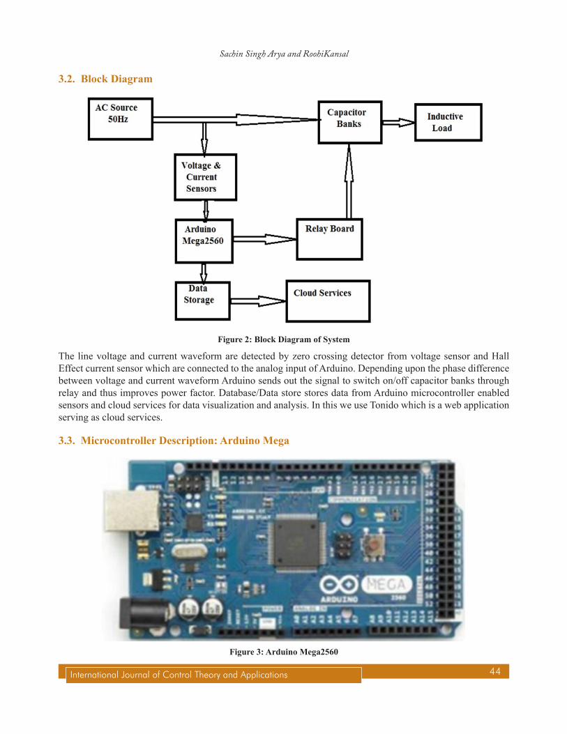
3.2. Block Diagram
Figure 2: Block Diagram of System
The line voltage and current waveform are detected by zero crossing detector from voltage sensor and Hall Effect current sensor which are connected to the analog input of Arduino. Depending upon the phase difference between voltage and current waveform Arduino sends out the signal to switch on/off capacitor banks through relay and thus improves power factor. Database/Data store stores data from Arduino microcontroller enabled sensors and cloud services for data visualization and analysis. In this we use Tonido which is a web application serving as cloud services.
3.3. Microcontroller Description: Arduino Mega
Figure 3: Arduino Mega2560

45 International Journal of Control Theory and Applications
Arduino Based Smart Power Factor corrector with Cloud Computing
The Arduino Mega 2560 is a microcontroller board based on the Atmega2560. It has 54 digital input/output pins of which 15 can be used as PWM outputs, 16 analog inputs, 4 UARTs hardware serial ports, a 16 MHz crystal oscillator, a USB connection, a powerjack, an ICSP header and a reset button. Fig3 show the basic structure of Arduino Mega.
Arduinoprovides programming environment which aid the developer to conduct, compile, upload, and simulate programs. By connecting an USB cable from computer to Arduino we can see serial data in real time and store it in text or in excel file [6].
Table 1 Features of Arduino Mega
Microcontroller At mega 2560
Operating Voltage 5 VRecommended Output Voltage 7-12 V
Input Voltage 6-20 VDigital I/O Pins 54Analog I/P Pins 16
DC Current per I/O Pin 40 mADc Current for 3.3 V Pin 50 mA
Flash Memory 256 KB out of which 8 KB used by bootloader
SRAM 8 KB
EEPROM 4 KB
Clock Speed 16 Hz
4. METHODOLOGYThe methodology on which my paper is based consist
4.1. Voltage Measurement Design
Figure 4: Voltage divider

46International Journal of Control Theory and Applications
Sachin Singh Arya and RoohiKansal
Voltage step down is a method that used for the purpose of stepping down the system voltage to a certain safe point to be fed into the system. In my project, to step down the voltage method used is voltage divider. A voltage divider is very simple circuit consists of two resistor which will turn a large voltage into a smaller voltage. For smaller voltage this method is very easiest and economical. The relationship between Vout and Vin in voltage divider is given by
Vout = inR1V
R1 R2+ (4)
4.2. Zero Cross Detector (ZCD)To detect the transition of voltage and current signal waveforms from positive and negative precisely when it hit the zero point, zero crossing detectors are used. The main concept of zero crossing detector operation is operational amplifier. In this thesis work, the operational amplifier is used as a voltage comparator. LM358 is selected because it has dual amplifiers inside it and only need one supply voltage which can be used for both the amplifiers. It also has wide power supply range which is 3V to 32V foe single supply and 1.5V to 16V for dual supplies.
4.3. Capacitor and relay board
Figure 5: Capacitor with relay board

47 International Journal of Control Theory and Applications
Arduino Based Smart Power Factor corrector with Cloud Computing
The simplest method of correcting power factor is by installing capacitors bank between the connection of source and load. The application of capacitors bank will be optimal if the load and the power factor are measured correctly, so the value of capacitors needed can be calculated precisely. By calculating the power factor before correction and the power factor desired, it is easier to find the correct value of capacitors needed. In this project, bulk compensation is used. This method allows the microcontroller to maintain the power factor value close to the desired one. This method uses several numbers of capacitors which connected to relays station. The relays connect or disconnect the capacitors to reduce the reactive power that produced by the load the relays are maintained directly from microcontroller. The connection of capacitor banks with relay board is shown in Figure5 [7].
Flowchart :
Start
Initialize
Read ADC
Remove DC offset by filter
Calculate active power
Measure Power Factor (PF)
No
Yes
Can PF be
improved?
Calculate Reactive Power (Q)
Choose suitable capacitance
Switch on desired
Capacitors
Figure 6: Flowchart of smart power factor

48International Journal of Control Theory and Applications
Sachin Singh Arya and RoohiKansal
4.4. Cloud Computingusing Tonido
Smart power factor is based on cloud computing which provides storage and computing resources to implement web applications. The main advantage of cloud services is that it can be accessed from anywhere and anytime in the world which is very useful. The main responsibility of web application is to read sensors value, store readings and monitoring household and commercial appliances over the internet. Further we use Coolterm software for serial data communication which stores sensor value on computer in text or excel file. For cloud computing we use Tonido which is remote access and home server software for network attached storage. Once it is installed on a computer this software makes the computer files available remotely through internet by using web browser or through mobile apps.It is public cloud software for establishing, expanding and maintaining our web applications because Tonido is very simple to use, extensible to service requests and have anadjustableinterface [4].
5. RESULTS AND DISCUSSION
5.1. Zero Crossing Detector Waveforms
Proteus software is usedto see the current, voltage phase shift waveforms and output of zero crossing detector before and after power factor correction. Yellow waveform represent voltage, blue waveform represent current and pink represent output of zero crossing detector.
Figure 7: Before power factor correction

49 International Journal of Control Theory and Applications
Arduino Based Smart Power Factor corrector with Cloud Computing
Figure 8: After Power factor Correction
5.2. Electrical Circuit Hardware Design
R.L Load (320W)
Arduino
Mcga 2560
Relay Board
Current Sensor and
Voltage Divider
Capacitor Bank
Figure 9: Arya: Pictorial view of System

50International Journal of Control Theory and Applications
Sachin Singh Arya and RoohiKansal
Comparative observation of Power factor of 320W RL load before and afterSmart power factor circuit insertion is shown below:
Table 2 Before power factor correction
Voltage(V) Current(A) W(watts) PF
230 2.2 500 0.5
Table 3 After power factor correction
Voltage(V) Current(A) W(watts) PF
230 1.4 322 0.9
The current and Power Factor of 320W RL load before applying capacitors bank are 2.2 A & 0.5. After apply capacitor banks of 20 Microfarad (uF) the current and Power Factor are 1.4A and 0.9 respectively.
5.3. Serial Data Communication through Coolterm
Figure 10: Serial data communication
6. CONCLUSIONThis project work is an effort to design and implement the smart power factor Controller using Arduino microcontroller. There is also provision to define the own current minimum range and power factor minimum and maximum range. Arduino monitors both ranges continuously and then takes the control action according to the lagging and leading power factor. Therefore it provide more reliable and easily operated power factor controller. From the project we can see that maintaining the power factor of a system is one way to save power usage and prevent power losses during the operation and also increase the efficiency of the system. Also Installation of capacitors banks in power factor correctionsystem will bring benefit for consumer and electrical agency. This thesis makes possibleto store the real time action taken by the Arduino and this stored data can be accessed from anywhere in the world using internetthrough cloud computing by which reliabilityand efficiency of the system can be increased.

51 International Journal of Control Theory and Applications
Arduino Based Smart Power Factor corrector with Cloud Computing
7. FUTURE SCOPEFuture scope In future, the smart power factor correction system can be expands to improve the power factor of multi loads. There are so many ways for correcting the power factor of a system and one of it by using capacitors bank. This work is not tested on static var compensator or synchronous condenser because of huge amount of expense is required. The usage of another microcontroller beside Arduino can be done to see the effectiveness. Cloud computing technology can provide future power system more computation power which can be addressed by utilizing all the available computer resources. In future certain new accurate and reliable method of connecting Arduino with cloud computing technology can be implemented.
REFERENCES[1] Aparna Sarkar”Automatic Power Factor Correction by Continuous Monitoring” International Journal of Engineering and
Innovative Technology (IJEIT) Volume 4, Issue 10, April 2015
[2] Murad Ali” Design and Implementation of Microcontroller-Based Controlling of Power Factor Using Capacitor Banks with Load Monitoring” Global Journal of Researches in Engineering Electrical and Electronics Engineering Volume 13 Issue 2 Version 1.0, 2013.
[3] Somnath Saha, Tushar Tyagi, Dhananjay V. Gadre “ARM® Microcontroller based Automatic Power Factor Monitoring and Control System”Texas Instruments India Educator Conference, 2013.
[4] Moataz Soliman, Tobi Abiodun, Tarek Hamouda, Jiehan Zhou, Chung-Horng Lung “Smart Home: Integrating Internet of Things with Web Services and Cloud Computing” IEEE International Conference on Cloud Computing Technology and Science 2013.
[5] N.Barsoum,” Programming for PIC microcontroller for power factor correction”, in Proc. 1st Asia Int. Conf. Modelling & Simulation, pp.19-25, 2007.
[6] Dr.Subhi R. M. Zeebaree, Hajar M. Yasin, “Arduino Based Remote Controlling for Home: Power Saving, Security and Protection” International Journal of Scientific & Engineering Research, Volume 5, Issue 8, August-2014
[7] M. Nagarajan and K.Kandasamy,” Optimal Power Factor Correction for Inductive Load Using PIC”, Procedia Eng, vol. 38, pp.737-744, 2012.
[8] M.Ravindran,V.Kirubakaran,” Electrical Energy Conservation in Automatic Power Factor Correction by Embedded System”, in Scientific&Academic Publication, 2012.
[9] ABB “Power factor correction and Harmonic filtering in electrical plants”, Technical Application Papers No. 8,2010.
[10] www.arduino.cc