Architecture and Applications of DSP Edutech Systems.
37
Architecture and Applications of DSP Edutech Systems
-
Upload
gavin-young -
Category
Documents
-
view
240 -
download
5
Transcript of Architecture and Applications of DSP Edutech Systems.
Architecture and Applications of DSP
Edutech Systems

About Edutech Systems
Interactive Learning Resource Development Company
Offers Learning Resources for Embedded and DSP learning
Firmware development Hardware consultancy services Training
Learning Resources
Tutors, CBT, WBT etc Simulators Compilers Programmers, Debuggers, Emulators CPU boards Interfacing Modules Laboratory Workbooks
What is Embedded System?
“An embedded system is an application that contains at least one programmable computer typically in the form of a microcontroller, a microprocessor or digital signal processor chip
Examples of Embedded Systems
Examples of embedded systems are Controller in washing machine, Controller in compact disk player, The navigation system in an
aircraft, The controller of a robot arm.
How ES are characterized? ESs are a special class of electronic
systems that can be briefly characterized by following terms:
Single-functioned Executes a single program, repeatedly
Tightly-constrained Low cost, low power, small, fast, etc.
Reactive and real-time Continually reacts to changes in the system’s
environment Must compute certain results in real-time without
delay
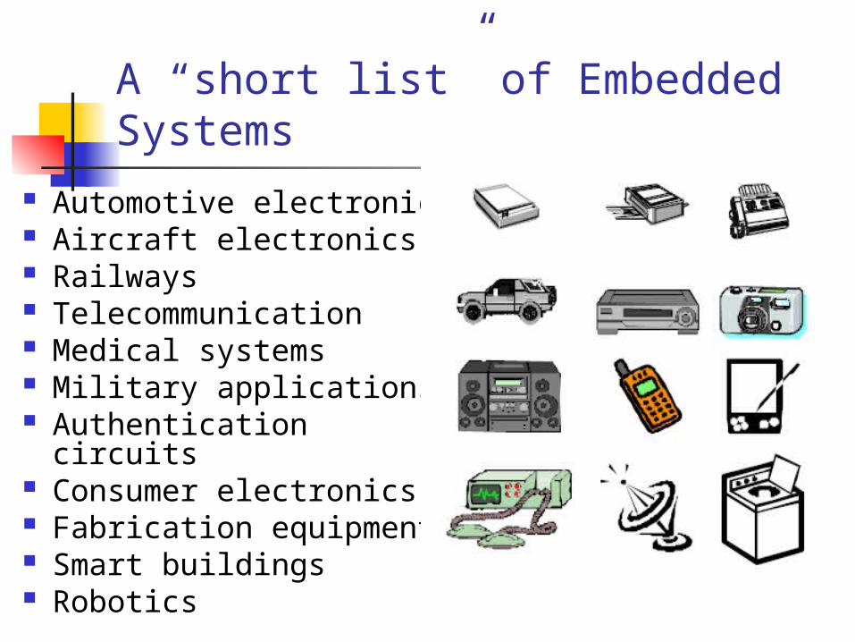
A “short list” of Embedded Systems
Automotive electronics Aircraft electronics Railways Telecommunication Medical systems Military applications Authentication circuits Consumer electronics Fabrication equipment Smart buildings Robotics
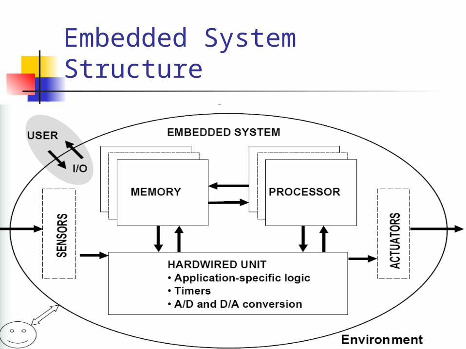
Embedded System Structure
Digital Signal Processing Digital Signal Processing (DSP) is concerned with the
digital representation of signals Digital signal processing is the mathematical
manipulation of an information signal to modify or improve it in some way.
Digital signal processing and analog signal processing are subfields of signal processing.
The goal of DSP is usually to measure, filter and/or compress continuous real-world analog signals.
Digital Signal Processor
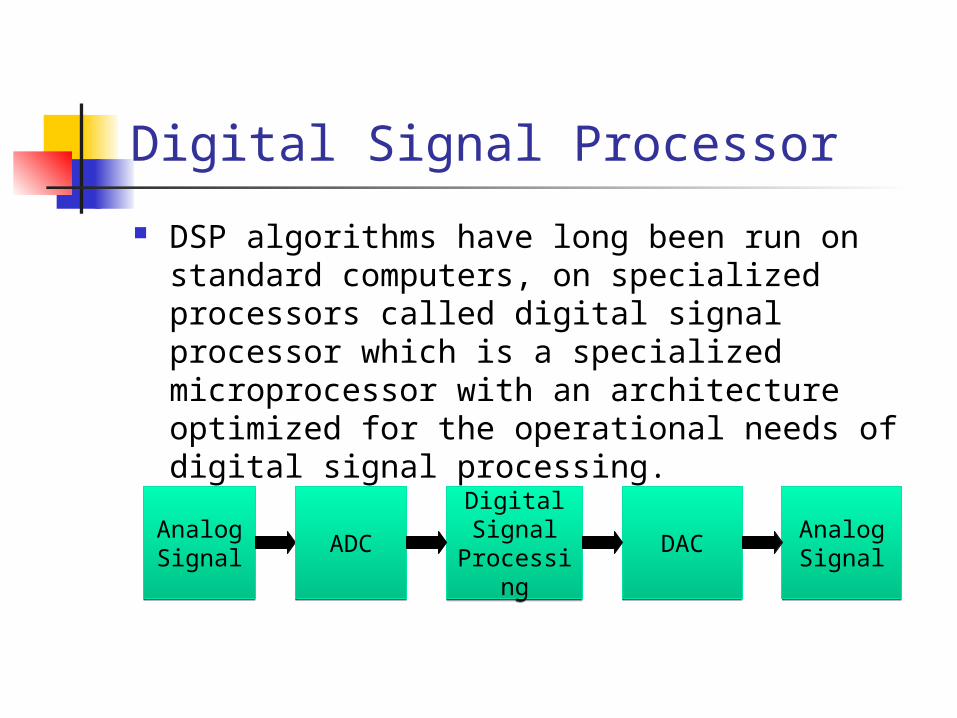
DSP algorithms have long been run on standard computers, on specialized processors called digital signal processor which is a specialized microprocessor with an architecture optimized for the operational needs of digital signal processing.
Analog Signal
Analog Signal ADCADC
Digital Signal
Processing
Digital Signal
Processing
DACDAC Analog SignalAnalog Signal
Applications of Digital Signal Processing
Audio and speech signal processing Sonar and radar signal processing Sensor array processing Spectral estimation Statistical signal processing Digital image processing Signal processing for communications Control of systems Biomedical signal processing Speech codec in cell phone
Overview of Signal Processing
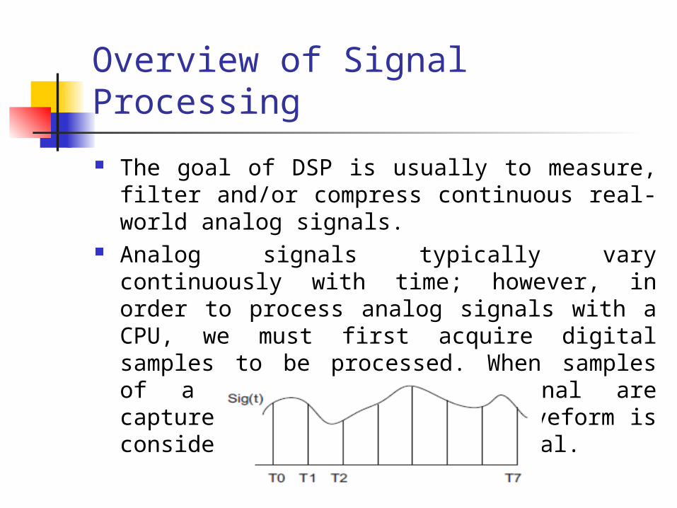
The goal of DSP is usually to measure, filter and/or compress continuous real-world analog signals.
Analog signals typically vary continuously with time; however, in order to process analog signals with a CPU, we must first acquire digital samples to be processed. When samples of a continuous input signal are captured as digital data, a waveform is considered a discrete time signal.
Overview of Signal Processing
The time between the samples is known as the sampling period. The sampling period is usually constant for a particular signal being sampled. The reciprocal of the sampling period is known as the sampling frequency fs.
The sampling frequency must be at least twice the bandwidth of the signal being processed according to the Nyquist sampling theorem.
Examples: Traditional telephony signals: 4 KHz, fs=8 KHz, samples every 125 ms
Wideband telephony signals: 8 KHz, fs=16 KHz, samples every 62.5 ms
CD audio signals: 22 KHz, fs=44 KHz, samples every 27 ms
DSP Building Blocks
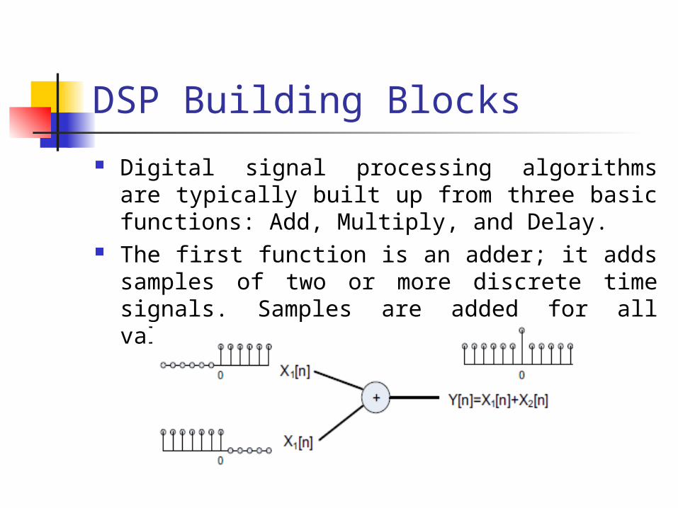
Digital signal processing algorithms are typically built up from three basic functions: Add, Multiply, and Delay.
The first function is an adder; it adds samples of two or more discrete time signals. Samples are added for all values of n, as shown in figure
DSP Building Blocks (Contd.)
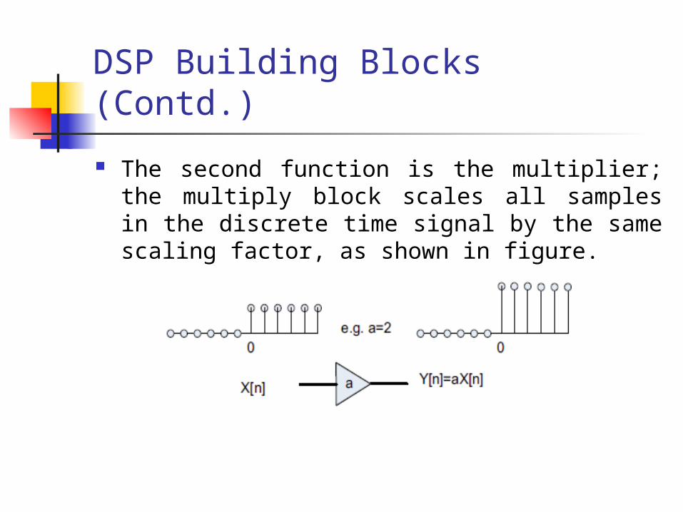
The second function is the multiplier; the multiply block scales all samples in the discrete time signal by the same scaling factor, as shown in figure.
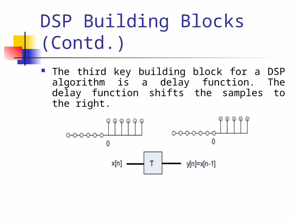
DSP Building Blocks (Contd.) The third key building block for a DSP algorithm is a
delay function. The delay function shifts the samples to the right.
DSP Building Blocks (Contd.)
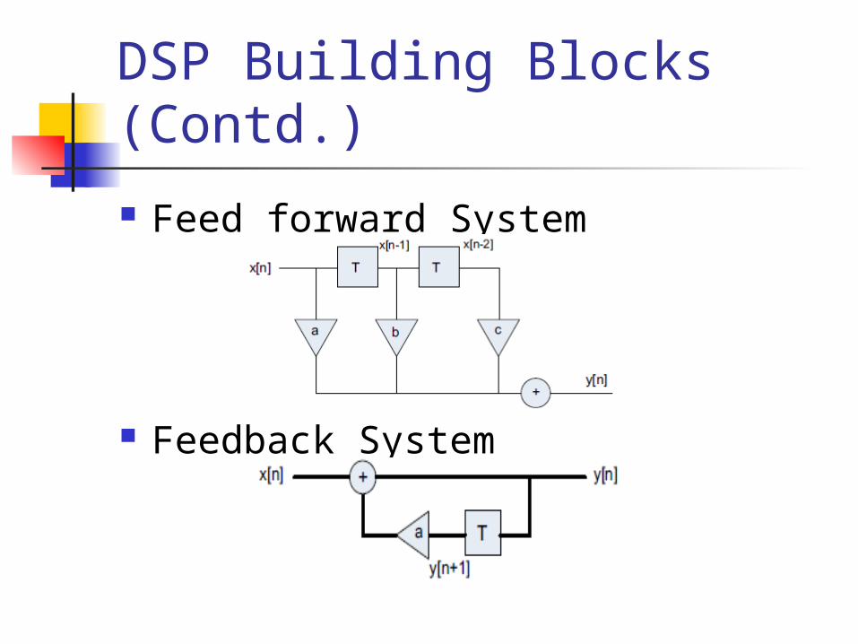
Feed forward System
Feedback System
Data Acquisition The A/D converts the sample analog signal and
provides an integer value representing the signal sampled. There are a wide range of A/D converters available with varying resolutions.
The resolution is defined by the number of bits used to represent the full range of the sampled signal; common resolutions are 8, 10, 11, 12, 14, 16, and 24 bits.
For audio sample acquisition component known as codec is attached via the HD audio interface.
The RealTek Codec is such a device that can be used to convert between the analog audio domain and the digital domain of the processor.
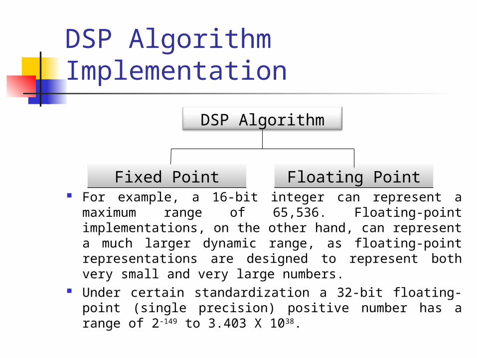
DSP Algorithm Implementation
For example, a 16-bit integer can represent a maximum range of 65,536. Floating-point implementations, on the other hand, can represent a much larger dynamic range, as floating-point representations are designed to represent both very small and very large numbers.
Under certain standardization a 32-bit floating-point (single precision) positive number has a range of 2-149 to 3.403 X 1038.
DSP Algorithm
Fixed PointFixed Point Floating PointFloating Point
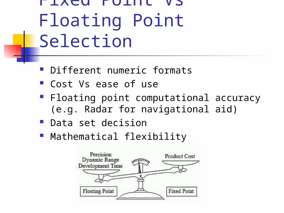
Fixed Point Vs Floating Point Selection Different numeric formats Cost Vs ease of use Floating point computational accuracy (e.g. Radar for
navigational aid) Data set decision Mathematical flexibility
COMPARISION BETWEEN DSPS & MICROCONTROLLER
Microcontrollers and Digital Signal Processors (DSPs) are the main engines of the deeply embedded development world.
A MICROCONTROLLER is a highly integrated chip which includes, on one chip, all or most of the parts needed for a controller, is used to control some process or aspect of the environment. The microcontroller could be called a "one-chip solution". DSPs are a high-speed single chip microprocessor or microcomputer designed to perform computer intensive digital signal processing tasks.
Microcontrollers are primarily used in control-oriented applications that are interrupt-driven, sensing and controlling external events.
DSPs, meanwhile, are traditionally found in systems that require the precision processing of analog signals.
Microcontrollers are inexpensive, small, and flexible. DSP is larger, more expensive, and more specialized.
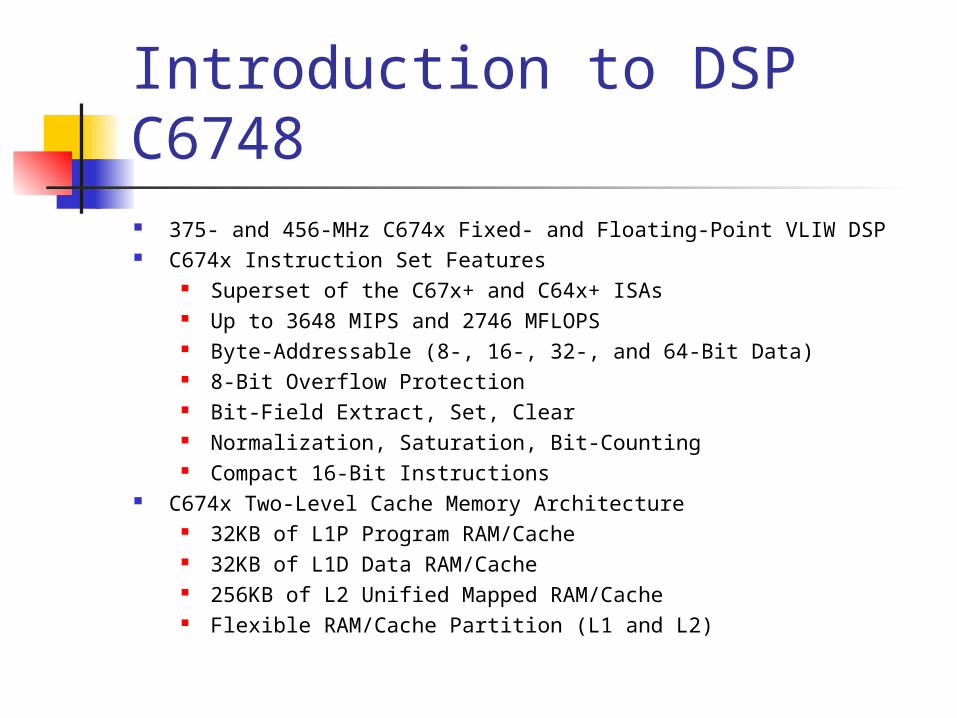
Introduction to DSP C6748 375- and 456-MHz C674x Fixed- and Floating-Point VLIW DSP C674x Instruction Set Features
Superset of the C67x+ and C64x+ ISAs Up to 3648 MIPS and 2746 MFLOPS Byte-Addressable (8-, 16-, 32-, and 64-Bit Data) 8-Bit Overflow Protection Bit-Field Extract, Set, Clear Normalization, Saturation, Bit-Counting Compact 16-Bit Instructions
C674x Two-Level Cache Memory Architecture 32KB of L1P Program RAM/Cache 32KB of L1D Data RAM/Cache 256KB of L2 Unified Mapped RAM/Cache Flexible RAM/Cache Partition (L1 and L2)
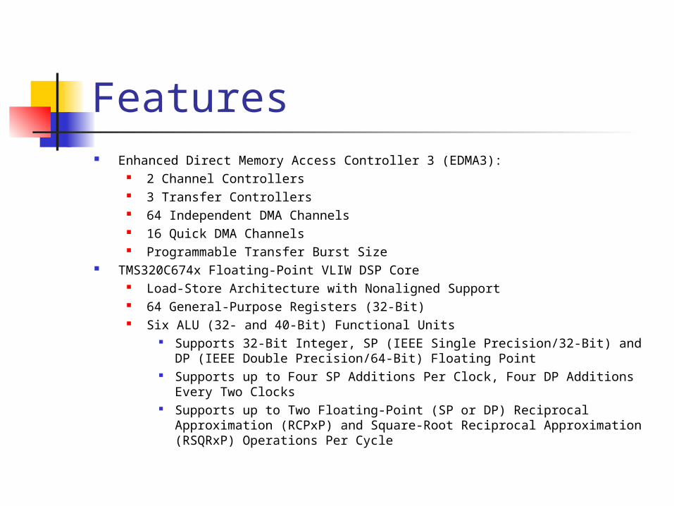
Features Enhanced Direct Memory Access Controller 3 (EDMA3):
2 Channel Controllers 3 Transfer Controllers 64 Independent DMA Channels 16 Quick DMA Channels Programmable Transfer Burst Size
TMS320C674x Floating-Point VLIW DSP Core Load-Store Architecture with Nonaligned Support 64 General-Purpose Registers (32-Bit) Six ALU (32- and 40-Bit) Functional Units
Supports 32-Bit Integer, SP (IEEE Single Precision/32-Bit) and DP (IEEE Double Precision/64-Bit) Floating Point
Supports up to Four SP Additions Per Clock, Four DP Additions Every Two Clocks
Supports up to Two Floating-Point (SP or DP) Reciprocal Approximation (RCPxP) and Square-Root Reciprocal Approximation (RSQRxP) Operations Per Cycle
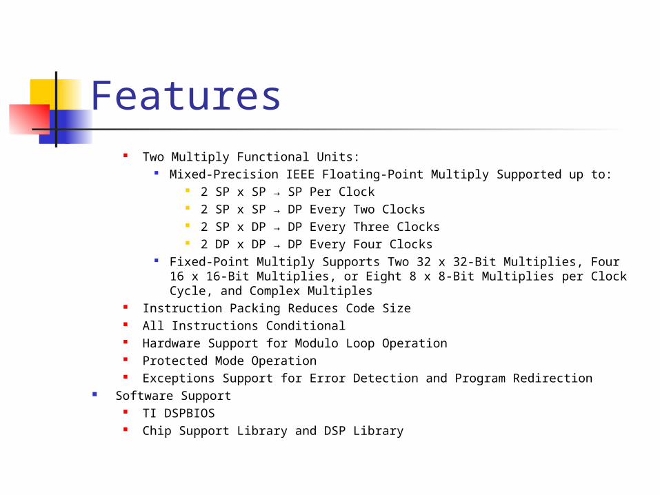
Features Two Multiply Functional Units:
Mixed-Precision IEEE Floating-Point Multiply Supported up to: 2 SP x SP → SP Per Clock 2 SP x SP → DP Every Two Clocks 2 SP x DP → DP Every Three Clocks 2 DP x DP → DP Every Four Clocks
Fixed-Point Multiply Supports Two 32 x 32-Bit Multiplies, Four 16 x 16-Bit Multiplies, or Eight 8 x 8-Bit Multiplies per Clock Cycle, and Complex Multiples
Instruction Packing Reduces Code Size All Instructions Conditional Hardware Support for Modulo Loop Operation Protected Mode Operation Exceptions Support for Error Detection and Program Redirection
Software Support TI DSPBIOS Chip Support Library and DSP Library
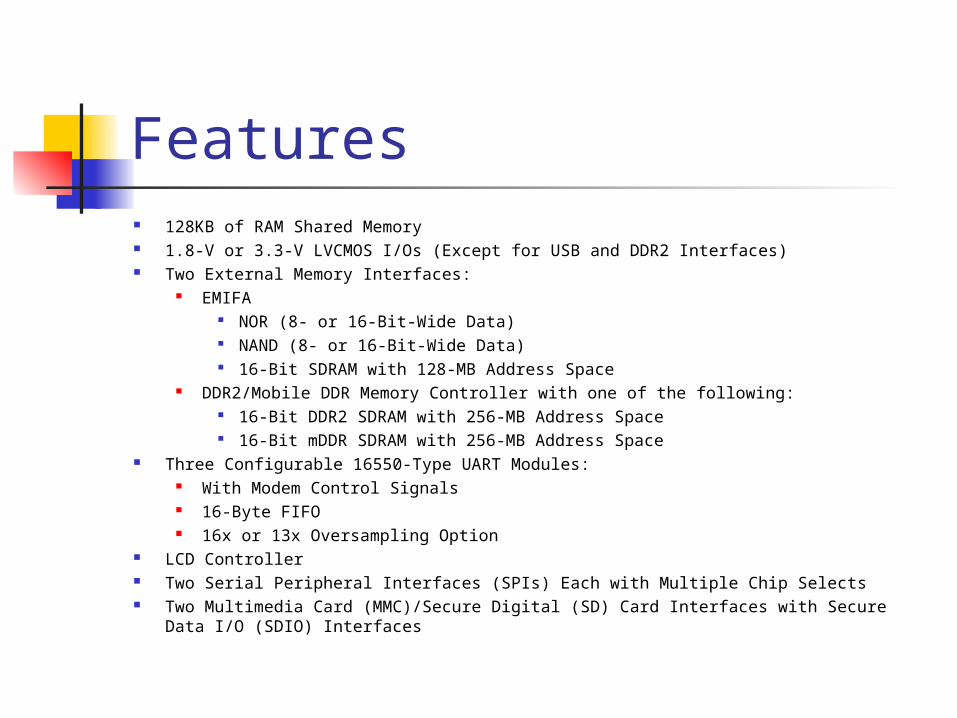
Features 128KB of RAM Shared Memory 1.8-V or 3.3-V LVCMOS I/Os (Except for USB and DDR2 Interfaces) Two External Memory Interfaces:
EMIFA NOR (8- or 16-Bit-Wide Data) NAND (8- or 16-Bit-Wide Data) 16-Bit SDRAM with 128-MB Address Space
DDR2/Mobile DDR Memory Controller with one of the following: 16-Bit DDR2 SDRAM with 256-MB Address Space 16-Bit mDDR SDRAM with 256-MB Address Space
Three Configurable 16550-Type UART Modules: With Modem Control Signals 16-Byte FIFO 16x or 13x Oversampling Option
LCD Controller Two Serial Peripheral Interfaces (SPIs) Each with Multiple Chip Selects Two Multimedia Card (MMC)/Secure Digital (SD) Card Interfaces with Secure Data I/O
(SDIO) Interfaces
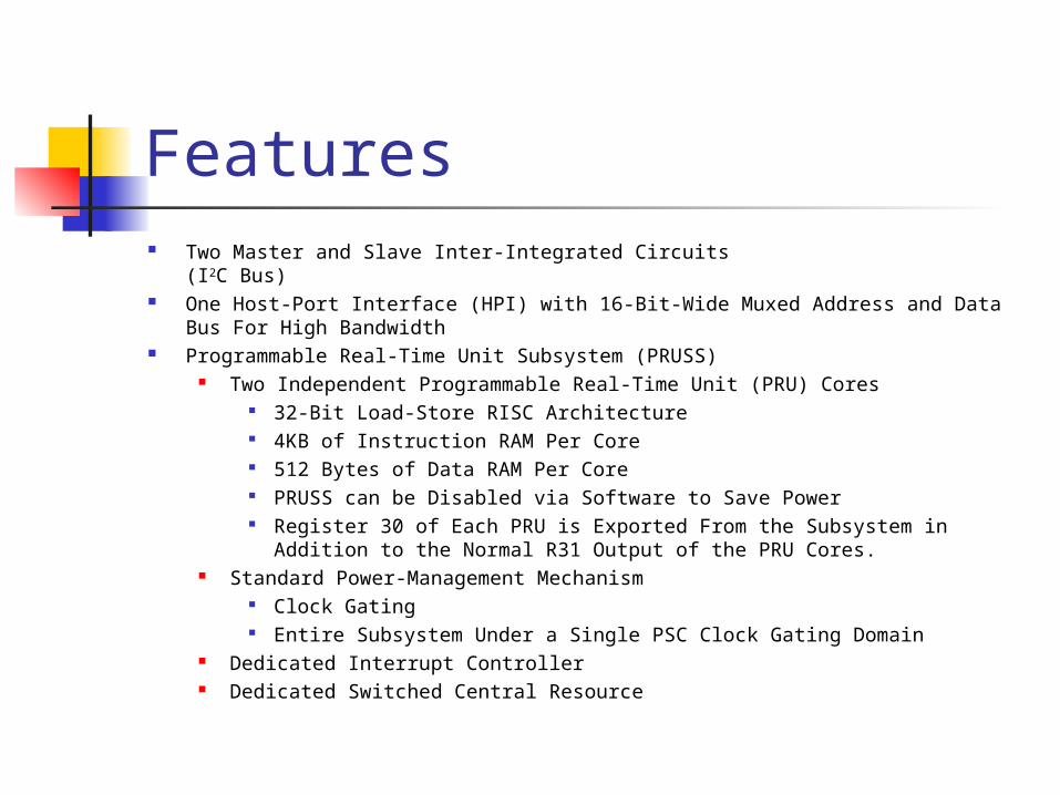
Features Two Master and Slave Inter-Integrated Circuits
(I2C Bus) One Host-Port Interface (HPI) with 16-Bit-Wide Muxed Address and Data Bus For
High Bandwidth Programmable Real-Time Unit Subsystem (PRUSS)
Two Independent Programmable Real-Time Unit (PRU) Cores 32-Bit Load-Store RISC Architecture 4KB of Instruction RAM Per Core 512 Bytes of Data RAM Per Core PRUSS can be Disabled via Software to Save Power Register 30 of Each PRU is Exported From the Subsystem in Addition to
the Normal R31 Output of the PRU Cores. Standard Power-Management Mechanism
Clock Gating Entire Subsystem Under a Single PSC Clock Gating Domain
Dedicated Interrupt Controller Dedicated Switched Central Resource
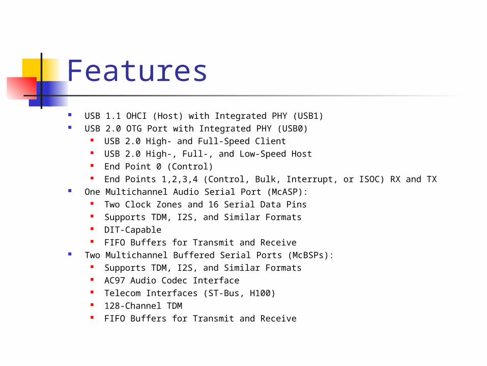
Features USB 1.1 OHCI (Host) with Integrated PHY (USB1) USB 2.0 OTG Port with Integrated PHY (USB0)
USB 2.0 High- and Full-Speed Client USB 2.0 High-, Full-, and Low-Speed Host End Point 0 (Control) End Points 1,2,3,4 (Control, Bulk, Interrupt, or ISOC) RX and TX
One Multichannel Audio Serial Port (McASP): Two Clock Zones and 16 Serial Data Pins Supports TDM, I2S, and Similar Formats DIT-Capable FIFO Buffers for Transmit and Receive
Two Multichannel Buffered Serial Ports (McBSPs): Supports TDM, I2S, and Similar Formats AC97 Audio Codec Interface Telecom Interfaces (ST-Bus, H100) 128-Channel TDM FIFO Buffers for Transmit and Receive
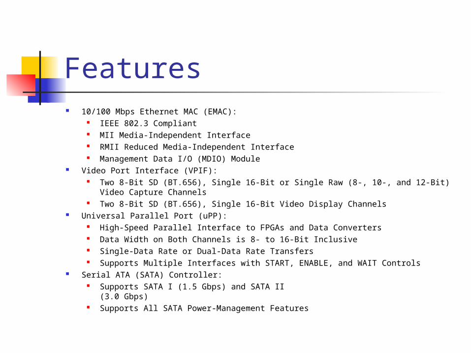
Features 10/100 Mbps Ethernet MAC (EMAC):
IEEE 802.3 Compliant MII Media-Independent Interface RMII Reduced Media-Independent Interface Management Data I/O (MDIO) Module
Video Port Interface (VPIF): Two 8-Bit SD (BT.656), Single 16-Bit or Single Raw (8-, 10-, and 12-Bit) Video
Capture Channels Two 8-Bit SD (BT.656), Single 16-Bit Video Display Channels
Universal Parallel Port (uPP): High-Speed Parallel Interface to FPGAs and Data Converters Data Width on Both Channels is 8- to 16-Bit Inclusive Single-Data Rate or Dual-Data Rate Transfers Supports Multiple Interfaces with START, ENABLE, and WAIT Controls
Serial ATA (SATA) Controller: Supports SATA I (1.5 Gbps) and SATA II
(3.0 Gbps) Supports All SATA Power-Management Features
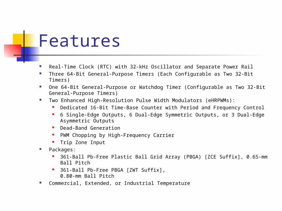
Features Real-Time Clock (RTC) with 32-kHz Oscillator and Separate Power Rail Three 64-Bit General-Purpose Timers (Each Configurable as Two 32-Bit Timers) One 64-Bit General-Purpose or Watchdog Timer (Configurable as Two 32-Bit
General-Purpose Timers) Two Enhanced High-Resolution Pulse Width Modulators (eHRPWMs):
Dedicated 16-Bit Time-Base Counter with Period and Frequency Control 6 Single-Edge Outputs, 6 Dual-Edge Symmetric Outputs, or 3 Dual-Edge
Asymmetric Outputs Dead-Band Generation PWM Chopping by High-Frequency Carrier Trip Zone Input
Packages: 361-Ball Pb-Free Plastic Ball Grid Array (PBGA) [ZCE Suffix], 0.65-mm Ball
Pitch 361-Ball Pb-Free PBGA [ZWT Suffix],
0.80-mm Ball Pitch Commercial, Extended, or Industrial Temperature
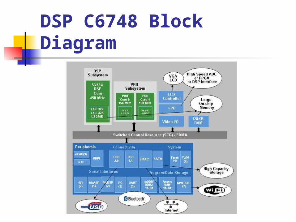
DSP C6748 Block Diagram
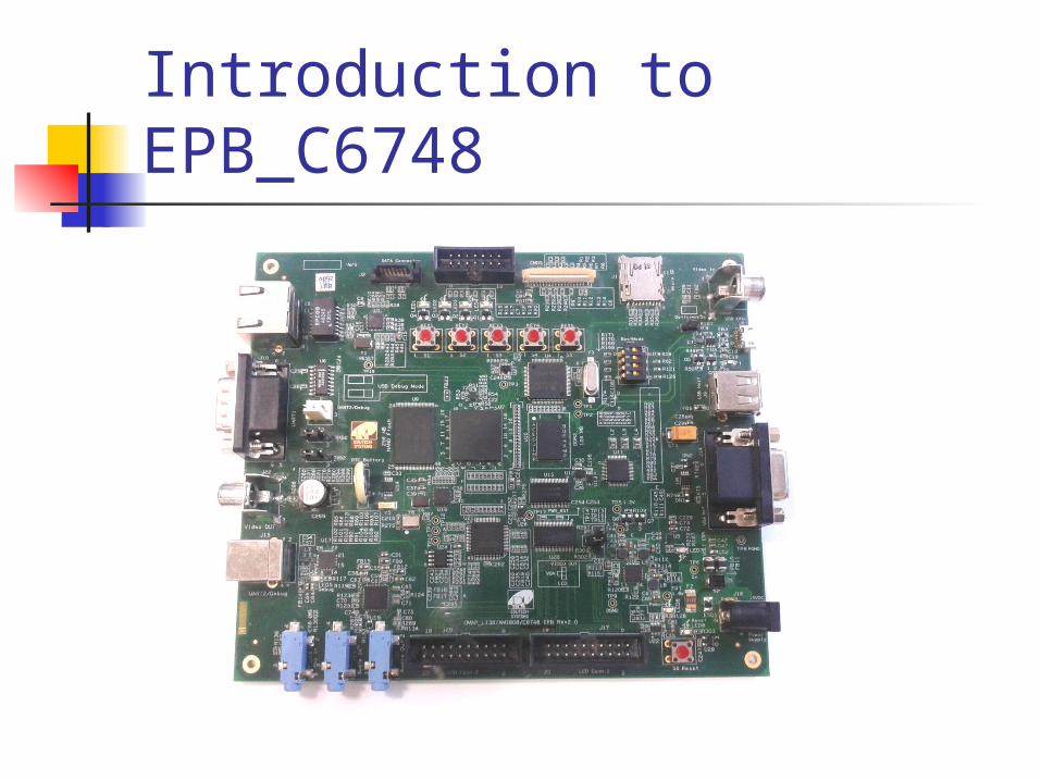
Introduction to EPB_C6748
EPB_C6748 FeaturesMechanical Parameters Size: 160mm x 136mm Input Voltage - 5V DC
Processor TMS320C6748 – Fixed/ Floating Point Digital Signal Processor DSP with up to 456 MHz performance. On board 14 Pin (2x7 Pin) JTAG emulation connector Boot mode selection switch Memory On board 256 MB Flash memory On board 128 MB DDR2 RAM memory
EPB_C6748 FeaturesData Transfer Interfaces On board DB9 connector for UART-1 interface On board 3 pin header for UART-2 interface On board USB TYPE B Connector for UART-2 interface for Debug Console LED indication for USB connection for Debug Console On board Reset Switch with LED indication On board USB Type A Connector for USB host interface On board micro USB Type A Connector for USB OTG interface On board RJ45 connector for 10/100 Ethernet interface On board I2C based Temperature sensor On board I2C based RTC interface with battery backup On board SPI based micro SD card interface On board SATA connector
EPB_C6748 FeaturesInput/Output Interfaces and other Facilities On board Power-On LED indication On board 4 User LED at GPIO Pin as GPIO Test point On board 5 user push buttons for various applications
Special functionality Boot mode selection switch On board Video in and Video out port available On board VGA out connector On board Graphics LCD interface connector On board audio jack and speaker(Mic in) interface and audio coded for speaker out On board CMOS sensor connector to interface CMOS camera On board Temperature sensor with interrupt out facility On board LED to indicate high voltage input On board excessive voltage protection circuit with LED indication Various test points for various signals
Hands-On Session with C6748
Creating a New Project Introduction to command file Introduction to Gel File Basic DSP based Examples Filter Examples Image Processing Video Processing

Thank You..!
Thank you..!

Thanks
EDUTECH SYSTEMSTEL: 0265-2438317Mail: [email protected]: www.edutechonline.com www.edutechlearning.com