Re-vision as Zapping: Tibor Fischer's The Collector Collector
Upload
surica-soricelCategory
view
32download
3
Architectural Integration of Photovoltaic and Solar Thermal Collector Systems into buildings
Master’s Thesis in Sustainable Architecture
June 2012, Trondheim
Arjun Basnet
Norwegian University of Science and Technology
Faculty of Architecture and Fine Arts
Department of Architectural Design, History and Technology


Supervisor: Nicola Lolli
Co-supervisor: Anne Grete Hestnes

i
ABSTRACT
In the time when the world is debating on climate change issues which is
basically due to use of fossil fuel, the use of solar energy in various form is
relevant. The existing buildings are responsible for use of large amount of
energy for lighting, heating, cooling and use of various energy run equipments
mostly powered by fossil energy. Today’s intention should be to replace this
fossil fuel by solar energy which is free and available in abundance.
At the moment, solar technologies in the form of photovoltaics and thermal
collectors are available in competitive prices. However, their use has not been
to the expectation specially in building sector to replace the use of fossil fuels.
The main reason for these technologies not being popular in building
integration is the lack of good architectural quality rendered not meeting
desired design considerations. Innovative approaches have to be explored in
terms of design and implementation in order to match the modern technological
components to the scale, proportion, material, colour scheme and balance of
buildings. So, the objective of this thesis is to pave possible ways of integrating
these technologies into buildings, both on existing and new constructions to
add emphasis on the overall architectural expression in addition to producing
energy. The intention here is to highlight design possibilities regarding the use
of solar technologies into buildings with innovative approaches. Basic focus is
on the appearance or aesthetics part of integration as this makes the major
impact on the people. PVs and thermal collectors can deliberately be used as
architectural design elements in a distinctive way.
The development towards passive house, zero energy and zero emission
buildings will cause a more frequent use of building integrated solar energy
systems as a source of renewable energy. Due to the limitations in the
integrability of such systems in relation to the design, colour and scale of the
building envelope, their integration may ruin the final architectural quality of the
building. Many solar systems do exist on the market, and with better and better
energy performance. But, if they are not designed to be integrated into
buildings to enhance the quality of architecture, probably no one will opt using
ii
these systems as a source of renewable energy generators. In this case, even
though there will be more and more efficient PV or STC systems in the market,
they won’t be of use if aesthetic ways of integrating them is not sought. It looks
like PV integration have brought about some improvements in the architectural
quality of building integration, but the solar thermal collectors lacks on this part
to some extent.
While the technical development and energy performance improvements are
always in progress, the actual use of these systems in buildings is not
increasing as it could and should do. Existing buildings account for over 40% of
the world’s total primary energy use and 24% of greenhouse gas emissions
(Wall, 2009). A combination of making buildings more energy-efficient and
using a larger fraction of renewable energy is therefore a key issue to reduce
the non-renewable energy use and greenhouse gas emissions. With this aim,
integration of PV and solar thermal collector systems into buildings becomes
very important.
Integrating these PV and solar thermal collectors systems into buildings is not
only for clean energy but also to use them as multifunctional elements where
they replace the conventional building elements. With this, the economical
viability of integration is met and most importantly, they become architectural
components.
So the possible ways of architectural integration of PV and solar thermal
collector systems have been explored and analysed in the thesis with special
focus made on the aesthetic part of integration. ‘Integrability’ of both the
systems in terms of different integration requirements have been compared. In
doing so, integration advantages of both the systems have been explored.
iii
ACKNOWLEDGEMENTS
This thesis is the result of support from the Faculty of Architecture and Fine
Arts, Professors, Teachers, Family and Friends.
My sincere thanks goes to Nicola Lolli for supervising and guiding me in due
course of producing this work. I would also like to acknowledge Professor Anne
Grete Hestnes for her precious time with the guidance, comments and support.
Her ever welcoming gesture made me feel at ease while discussing issues
related to the study. Associate Professor Annemie Wyckmans, the co-ordinator
of our program, needs special acknowledgment for her valued suggestions.
My colleagues Alise, Chenchen, Elisabeth, Elisabetta, Ivan, Kristof, Lin, Maria,
Michael, Mila,Nigar, Noora and Vegard need mentioning for their companion for
the two years of study.
Last but not the least; I would also like to extend love and gratitude to my
parents, my wife and my beautiful daughter for their support, understanding
and love.

iv

v
CONTENTS
ABSTRACT..................................................................................................................... i ACKNOWLEDGEMENTS ............................................................................................. iii CONTENTS.................................................................................................................... v
LIST OF FIGURES........................................................................................................ ix
ABBREVIATIONS ......................................................................................................... xi 1 INTRODUCTION .................................................................................................... 1
1.1 Need for renewable energy ............................................................................ 1
1.2 Solar energy ................................................................................................... 2
1.3 Solar technologies in building ......................................................................... 3
1.4 Research Question ......................................................................................... 4
1.5 Scope of Research ......................................................................................... 5
1.6 Structure of thesis ........................................................................................... 5
2 LITERATURE ......................................................................................................... 6
2.1 Photovoltaic .................................................................................................... 6
2.1.1 Photovoltaic Cells ..................................................................................... 6
2.1.2 PV modules ............................................................................................ 11
2.2 Solar Thermal Collectors .............................................................................. 11
2.2.1 Air-based collector systems .................................................................... 11
2.2.2 Water-based collector systems ............................................................... 12
2.3 PV and STC Integration ................................................................................ 16
3 ARCHITECTURAL INTEGRATION AND BUILDING INTEGRATION ................ 18
3.1 Building Integration ....................................................................................... 18
3.2 Difference between architectural integration and building integration .......... 20
3.3 Does architectural integration really boost aesthetics of a building? ............ 21
3.4 What are the challenges between integration into existing and new building? 22
3.5 Good Integration ........................................................................................... 23
3.6 Integration of PV and STC modules in buildings .......................................... 23
3.7 Integration Method ........................................................................................ 24
3.7.1 Superimposed ......................................................................................... 24
3.7.2 Integrated................................................................................................ 24
4 INTEGRATION OF PHOTOVOLTAICS ............................................................... 25
4.1 Roof Integration of PV .................................................................................. 26
4.1.1 PVs on flat roof ....................................................................................... 28
4.1.2 PVs on Inclined/ Pitched roof .................................................................. 28
vi
4.1.3 Roof with integrated PV tiles ................................................................... 30
4.1.4 PV in saw-toothed north light roof/ sky light ............................................ 31
4.1.5 PVs on Curved roof/wall ......................................................................... 32
4.1.6 PVs in Atrium/skylights ........................................................................... 33
4.2 Facade integration of PV .............................................................................. 34
4.2.1 Vertical integration of PV ........................................................................ 36
5 INTEGRATION OF SOLAR THERMAL COLLECTOR ....................................... 41
5.1 Roof Integration of STC systems .................................................................. 41
5.1.1 Integration on Flat roof ............................................................................ 42
5.1.2 Integration on Pitched roof ...................................................................... 43
5.2 Facade Integration of STC systems ............................................................. 44
5.2.1 Direct facade integration ......................................................................... 45
5.2.2 Solar thermal collectors as balcony railings ............................................ 47
6 QUALITY OF ARCHITECTURAL INTEGRATION .............................................. 49
6.1 Functional Aspect of Architectural integration .............................................. 49
6.2 Constructive aspect of Architectural Integration ........................................... 51
6.3 Formal (aesthetic) aspect ............................................................................. 53
7 ARCHITECTURAL INTEGRATION REQUIREMENTS ....................................... 56
7.1 Field Size and Position ................................................................................. 56
7.2 Materials and surface texture ....................................................................... 59
7.3 Colour ........................................................................................................... 60
7.4 Shape and size of the modules .................................................................... 61
7.5 Type of Jointing ............................................................................................ 61
7.6 Multifunctional Elements ............................................................................... 62
8 PV OR STC: BETTER ABILITY TO ARCHITECTURAL INTEGRATION? ......... 63
8.1 Shape and size ............................................................................................. 64
8.2 Positioning .................................................................................................... 65
8.3 Flexibility in integration ................................................................................. 66
8.4 Range of Colours .......................................................................................... 67
8.5 Surface texture and finish ............................................................................. 70
8.6 Visible Jointing of Modules ........................................................................... 71
8.7 Multi-functionality .......................................................................................... 72
8.8 Transportation of Energy .............................................................................. 74
8.9 Storage ......................................................................................................... 74
8.10 Effect of Shading .......................................................................................... 75
8.11 Efficiency per unit area ................................................................................. 75
8.12 Useful life time .............................................................................................. 76
vii
8.13 Temperature ................................................................................................. 76
8.14 Cost .............................................................................................................. 77
9 ARCHITECTURE INTEGRATION EVALUATION OF SELECTED PROJECTS 78
9.1 Photovoltaic: Mono-crystalline cells .............................................................. 78
9.2 Photovoltaic: Poly-crystalline cells ................................................................ 80
9.3 Photovoltaic: Thin-film cells .......................................................................... 82
9.4 Solar Thermal Collector: Glazed flat plate .................................................... 84
9.5 Solar thermal collectors: Vacuum tubes ....................................................... 86
9.6 Solar thermal collectors: Unglazed collectors ............................................... 88
10 CONCLUSION ..................................................................................................... 90
REFERENCES ............................................................................................................. 92

viii
ix
LIST OF FIGURES
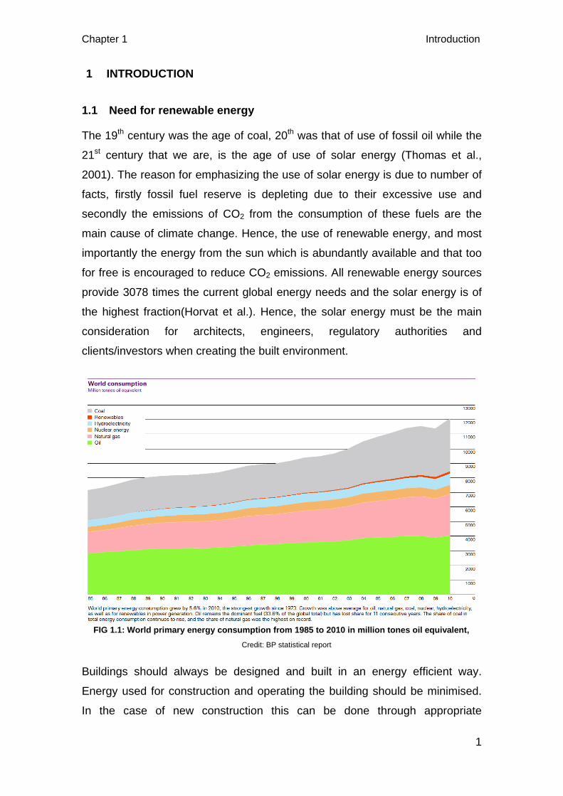
FIG 1.1: World primary energy consumption from 1985 to 2010 in million tones oil equivalent, . 1
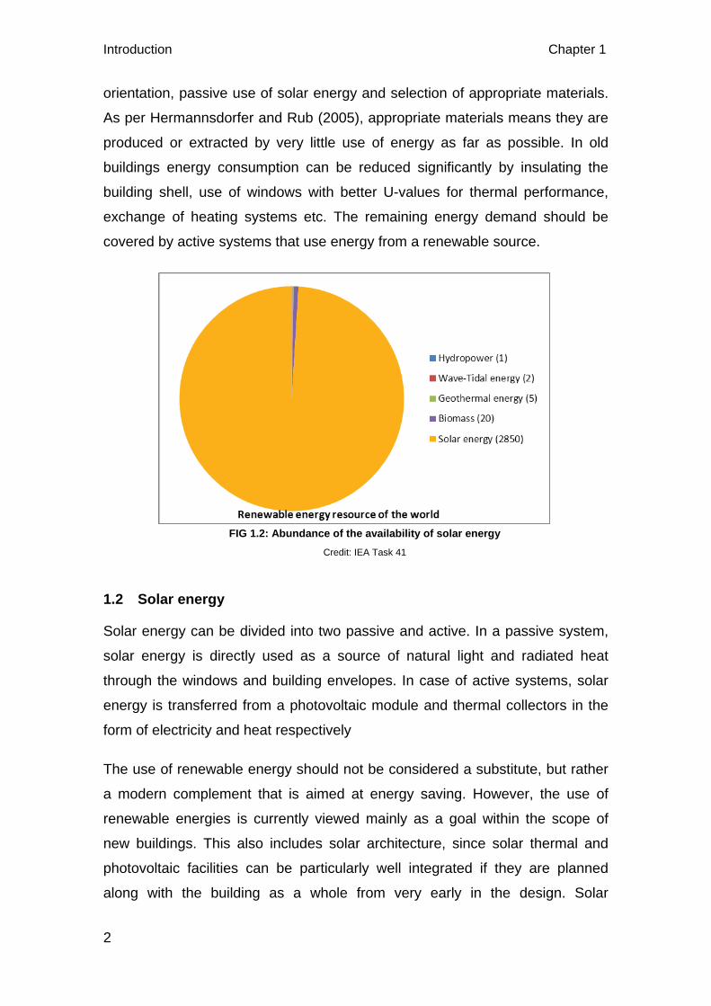
FIG 1.2: Abundance of the availability of solar energy ................................................................. 2
FIG 2.1: Types of photovoltaic cells .............................................................................................. 8
FIG 2.2: Vauxhall transport interchange ....................................................................................... 8
FIG 2.3: Doxford Solar Office ....................................................................................................... 9
FIG 2.4: The photovoltaic principle, .............................................................................................. 9
FIG 2.5: Air based collector system ............................................................................................ 12
FIG 2.6: (Left) evacuated tubes (Right) evacuated tube collector set .......... 13
FIG 2.7: (Left) Parts of flat plate solar thermal collector (Right) Collectors on to the roof .................................................................................................................................................... 14
FIG 2.8 (Left) Unglazed flat plate collectors integrated on the façade, (Right top, bottom) Unglazed flat plate collectors integrated on the roof .................................................................. 15
FIG 2.9: Unglazed plastic collectors ........................................................................................... 16
FIG 3.1: Elegant use of solar thermal collectors on the curved roof of ‘Solar City’, housing development in the suburb Plan-les-Quates, Switzerland .......................................................... 19
FIG 3.2: (Left) Office building at NTNU before PV integration, (Right) Same building after PV integration on the glass façade ................................................................................................... 21
FIG 4.1: PV integrated double glazed roof of Café Ambiente, Germany ................................... 27
FIG 4.2: PV combined with a thermal system (PVT) façade of Fiat Research Center ............... 28
FIG 4.3: (Left) PV modules added on to the roof as pure technical element, (Right) Semi-integrated PV modules on the Roof ............................................................................................ 29
FIG 4.4: (Left) Integrated PV on the pitched roof of vacation house Bartholomä-Park in Germany (Right) Integrated PV roofs in Schlierberg Solar Settlement in Freiburg ................... 30
FIG 4.5: Integrated PV roof tiles on the roof ............................................................................... 31
FIG 4.6 (Left) Integrated PV on the saw-toothed glass roof of Paul Lobe Haus, Berlin (Right) Sawtooth roof with PV integration, DIY store, Hamburg ............................................................. 31
FIG 4.7: PV integration on the curved roof of BP solar Showcase in Birmingham ..................... 32
FIG 4.8: (Left) Atrium with PV modules, Ludesch/Vlbg., Austria; (Right) PV on coloured skylights at Bejar Market, Salamnca, Spain ............................................................................... 33
FIG 4.9: PV integrated into the opaque parts of the façade of Solar XXI building, Portugal ...... 35
FIG 4.10: Tobias Grau Production Building in Germany has PV integrated into it south glazed facade ......................................................................................................................................... 36
FIG 4.11: Saw-tooth PV facade consisting of overhanging PV shade screens .......................... 36 FIG 4.12: Inclined PV integrated glazed façade of Vocational College in Tirol, Austria .......... 37
FIG 4.13: Inclined PV integrated façade of Solar-Fabrik building, Freiburg, Germany .............. 38
FIG 4.14: PV integrated inclined wall of Daxford Solar Office .................................................... 38
FIG 4.15: PV used as shading in the Energy Research Centre, Netherlands ............................ 39
FIG 4.16: PV integrated into the glass louvered sun-shades in the Editing office, Albstadt-Ebingen, Germany ...................................................................................................................... 40
FIG 5.1: Solar thermal collector laid on flat roof of Holiday housing Jois, Austria ...................... 43
FIG 5.2: Integration of STC on the pitched roof of single-family house ...................................... 43
x
FIG 5.3: Integrated STC systems in Hamburg Bramfeld multi-family house, Germany ............. 44
FIG 5.4: Integrated STC systems on the façade of office building of AKS DOMA Solartedhnik 46
FIG 5.5: Façade integration of unglazed flat-plate collector, CeRN, Switzerland ...................... 47
FIG 5.6: Use of evacuated tube collectors as balcony railings, Sunny Woods multi-family housing in Zurich, Switzerland .................................................................................................... 48
FIG 6.1: (Left) Integration of PV as shading and daylight control; (Right) Evacuated Tube collector used as balcony railing ................................................................................................. 51
FIG 6.2: Venting cavity behind the PV modules in BP Solar skin building, NTNU, Trondheim .. 53
FIG 6.3: Integration of PV, considering the formal aspect. (Left) Monte Rosa Hut, (Right) Novartis Building, Switzerland .................................................................................................... 54
FIG 6.4: PV integration as a show element, College of Fine Arts, Hamburg Germany ............. 55
FIG 7.1: Architectural integration of PV on the roof of a Church, Carlow, Germany. The formal characteristics of the PV system have an impact on the integration quality. .............................. 58
FIG 7.2: Architectural integration of STC systems on the inclined façade of multifamily dwelling, Gleisdorf, Germany. The formal characteristics of the STC system have an impact on the integration quality. ....................................................................................................................... 58
FIG 7.3: Illustrations of some possible variations in the surface texture of PV .......................... 59
FIG 7.4: (Left) Range of colours in PV; (Right) visible colours due to the sunlight striking onto the extra white glass above the absorber of STC system, ......................................................... 61
FIG 7.5: (top-left): Integration of PV shingles on the façade of Surplus-home of team Germany, (Bottom-left): Jointing of PV shingles used, (Top-right): Integration of STC system in the multifamily dwelling, Gleisdorf, Austria, (Bottom-right): Jointing of STC in the multifamily dwelling, ...................................................................................................................................... 62
FIG 8.1: (top-left): PV tiles on the roof, (bottom-left): PV on the roof Delamont Country Park Ireland building, (center & right): Techtile Therma STC systems on the roof ............................. 65
FIG 8.2: Range of colours in PV cells, ........................................................................................ 67
FIG 8.3: (Left): PV modules based on Metallic Gold cells are integrated in the balcony, rails and facade, Tirol, Austria ................................................................................................................... 68
FIG 8.4: Multi-crystalline PV system with bronze and gold coloured silicon solar cells used in the "home+" building project submitted by Stuttgart University of Applied Sciences, ................ 69
FIG 8.5: One of the first applications of the multifunctional use of PV systems in the administrative building on the Stadtwerke, Aachen, Germany, .................................................. 73
FIG 8.6: Multifunctional use of STC systems in the façade of the housing in Bjoernveien, Oslo, .................................................................................................................................................... 73
FIG 8.7: Affect of shading to PV modules(right) and the result (left), ......................................... 75
FIG 9.1: Mono-crystalline PV cladding on the glass façade, BP Solar building, NTNU, Trondheim, .................................................................................................................................. 79
FIG 9.2: Integration of coloured poly-crystalline solar cells, Paul Horn Arena, Tübingen Germany .................................................................................................................................... 81
FIG 9.3: Integration of thin-film PV on the sliding sunshading, Dwelling houses Spinnereistraße, Austria, ........................................................................................................................................ 83
FIG 9.4: Integration of glazed-flat plate collectors, Social housing , Paris France ..................... 85
FIG 9.5: Integration of evacuated collectors as balcony railings, Sunny Woods, Switzerland ... 87
FIG 9.6: Façade integration of unglazed flat plate collectors as multifunctional cladding element, (CeRN), Switzerland. ................................................................................................... 89
xi
ABBREVIATIONS
BIPV: Building Integrated Photovoltaic
EAESL: The Encyclopedia of Alternative Energy and Sustainable Living
EERE: Energy Efficiency and Renewable Energy
EST: Energy Saving Trust
PV: Photovoltaic
STC: Solar Thermal Collector

xii
Chapter 1 Introduction
1
1 INTRODUCTION
1.1 Need for renewable energy
The 19th century was the age of coal, 20th was that of use of fossil oil while the
21st century that we are, is the age of use of solar energy (Thomas et al.,
2001). The reason for emphasizing the use of solar energy is due to number of
facts, firstly fossil fuel reserve is depleting due to their excessive use and
secondly the emissions of CO2 from the consumption of these fuels are the
main cause of climate change. Hence, the use of renewable energy, and most
importantly the energy from the sun which is abundantly available and that too
for free is encouraged to reduce CO2 emissions. All renewable energy sources
provide 3078 times the current global energy needs and the solar energy is of
the highest fraction(Horvat et al.). Hence, the solar energy must be the main
consideration for architects, engineers, regulatory authorities and
clients/investors when creating the built environment.
Buildings should always be designed and built in an energy efficient way.
Energy used for construction and operating the building should be minimised.
In the case of new construction this can be done through appropriate
FIG 1.1: World primary energy consumption from 1985 to 2010 in million tones oil equivalent, Credit: BP statistical report
Introduction Chapter 1
2
orientation, passive use of solar energy and selection of appropriate materials.
As per Hermannsdorfer and Rub (2005), appropriate materials means they are
produced or extracted by very little use of energy as far as possible. In old
buildings energy consumption can be reduced significantly by insulating the
building shell, use of windows with better U-values for thermal performance,
exchange of heating systems etc. The remaining energy demand should be
covered by active systems that use energy from a renewable source.
1.2 Solar energy
Solar energy can be divided into two passive and active. In a passive system,
solar energy is directly used as a source of natural light and radiated heat
through the windows and building envelopes. In case of active systems, solar
energy is transferred from a photovoltaic module and thermal collectors in the
form of electricity and heat respectively
The use of renewable energy should not be considered a substitute, but rather
a modern complement that is aimed at energy saving. However, the use of
renewable energies is currently viewed mainly as a goal within the scope of
new buildings. This also includes solar architecture, since solar thermal and
photovoltaic facilities can be particularly well integrated if they are planned
along with the building as a whole from very early in the design. Solar
FIG 1.2: Abundance of the availability of solar energy
Credit: IEA Task 41
Chapter 1 Introduction
3
technologies imply vast opportunities for aesthetics and interesting solutions
and solar heating technology is amongst the least expensive in the area of
renewable energy (Hermannsdorfer and Rub, 2005; Kjellerup et al., 2010).
1.3 Solar technologies in building
The importance of planning and design concepts that contribute to an increase
in public acceptance of the solar building through convincing visualization and
realization has to be emphasized. The installation of a solar facility during the
renovation of an existing building produces both synergies and savings. If, for
eg; a roof has to be completely recovered and a solar facility is installed, cost
on tiling is saved in addition to energy generation. Solar facilities can also be
easily integrated into planned extensions such as conservatories
(Hermannsdorfer and Rub, 2005).
Use of solar energy for electricity and heating is a silent and non-polluting way
that requires minimum maintenance. However, their integration into buildings
represents a real architectural challenge, as to a great degree, the
development of solar systems for energy has been characterized by the wish
for energy effectiveness and low cost, while the architectural aspects have
been neglected. In fact, these systems can be integrated into buildings as a
multifunctional element that increases the architectural quality besides
providing free energy(Kjellerup et al., 2010).
It is important that we do not regard solar facilities as technological systems
that only serve the purpose of producing heat or electricity; instead, they must
be regarded and treated as elements that make an important contribution to the
architectural design. Thus seen, they can enhance the architecture, accentuate
it and distinguish it from the mass. They can express adaptation and
transformation or modernity while at the same time are able to preserve
traditional features. With this, both the building and the owner will have a
positive image on architectural integration (Hermannsdorfer and Rub, 2005).
Integration on existing buildings unavoidably tend to be more fragmented than
on new buildings, since they have to comply with an existing context. As
standardized products are often not applicable, the situation calls for innovative
Introduction Chapter 1
4
approaches. Existing buildings, monuments and landscapes mainly call for a
slight integration of the technological components such as PV and STC
systems into the given context (Hermannsdorfer and Rub, 2005). In case of
new buildings, integration becomes much easier and renders quality if it is
thought of right from the conceptual stage
1.4 Research Question
With a brief explanation of PV and STC integration into the buildings above,
I have formulated a research question in order to focus the study basically
on the aesthetics or formal aspect of integration. The question is:
How can the Photovoltaic and solar thermal collector systems be integrated
into buildings to serve the dual purpose of generating solar energy and
enhancing architectural quality?
I have tried to answer the above question in a structured form by studying,
analyzing and explaining all aspects related to the architectural integration
of these PV and STC systems. The following supporting questions will
further help find answer to architectural integration in a more simple way.
The whole thesis is the answer to these questions.
- What is the difference between architectural integration and building
integration? What is architectural integration of Photovoltaic and solar
thermal collector systems?
- What are the challenges between integration into existing and new
building?
- Does integration of these systems really boost the architectural quality of
the buildings?
- To what extent can energy generation be compromised over
architectural aesthetics and vice versa?
Chapter 1 Introduction
5
1.5 Scope of Research
The research is basically confined to the architectural integration of PV and
STC systems into buildings, both new construction and existing. I have not
considered integration into urban spaces and landscapes rather focused on
integrating into buildings on individual basis. Different aspects of integration
have been explained with relevant examples to make the study illustrative and
easy to understand.
1.6 Structure of thesis
The main objective of this study is to find out different possible and relevant
ways of architectural integration of PV and STC systems into buildings mainly
in order to enhance the overall architectural expression of the building in
addition to using them as building elements. It is done with an aim that if these
systems help enhance the quality of architecture and will appeal both the
building owners and designers; they will definitely develop as regular and
normal building components in the days to come.
The study begins with a brief theoretical study of the systems in the 2nd chapter
highlighting some technical aspects that is important in the integration process.
The 3rd chapter is an attempt to understand architectural integration by
answering to some aspects in the research question. Then the integration of
PV and STC systems are discussed separately in the 4th and 5th chapter.
Chapter 6 basically talks about the quality of architectural integration on the
basis of functional, construction and formal issues. The formal issues related to
architectural integration is the main focus of the thesis. Guidelines have been
drawn in chapter-7 underlying various aspects that will elaborately address and
influence the visual expression of the buildings. With these guidelines as the
point of departure, an attempt has been made to compare the two solar
technologies in terms of their architectural integration abilities in chapter-8.
Before concluding, architectural integration evaluation of some selected
projects have been made based on the type of systems integrated in chapter-9.
Literature Chapter 2
6
2 LITERATURE
2.1 Photovoltaic
It has been long until electricity was actually generated from photovoltaic since
the discovery of photovoltaic effect in 1839 (EERE). These systems are usually
based on silicon and are used to convert solar radiation into electricity. Direct
current (DC) is generated when the devices are exposed to sunlight. The
electricity generated is either used directly into DC appliances or converted
using inverters to run AC appliances. The DC current can also be stored in
batteries for use during the night when the PV systems don’t produce
electricity. PVs respond to both direct and diffused radiation and the output
increases with increasing sunshine which is called irradiance while decrease
with the module’s rise in temperature. Common PVs available are mono-
crystalline silicon, polycrystalline silicon and thin film silicon called amorphous
silicon (A-Si) (Thomas et al., 2001).
2.1.1 Photovoltaic Cells
Photovoltaic systems are sustainable, environmental friendly, quiet, light and
require minimal maintenance as they have no moving parts. In a PV system,
cells combine to form modules, which give the system the flexibility to be
expanded or reduced to suit any given application. The versatility of PV panels
gives numerous possibilities for their integration into new and existing
structures. Although the most commonly used cell types come from the same
base material silicon, different technologies offer cells with different technical
and aesthetic characteristics.
2.1.1.1 Mono-crystalline cells Mono-crystalline cells are cut into thin wafers from a singular continuous crystal
that has been grown for this purpose, hence are also called single crystal cells. To minimize waste, the cells may be fully round or they may be trimmed into
other shapes, retaining more or less of the original circle. As each cell is cut
from a single crystal, it has a uniform color (Solar, 2011). Mono-crystalline
silicon modules normally appear as a solid colour, ranging from blue to black. A
wide variety of colours is available but these are of lower efficiency. Eg:
Chapter 2 Literature
7
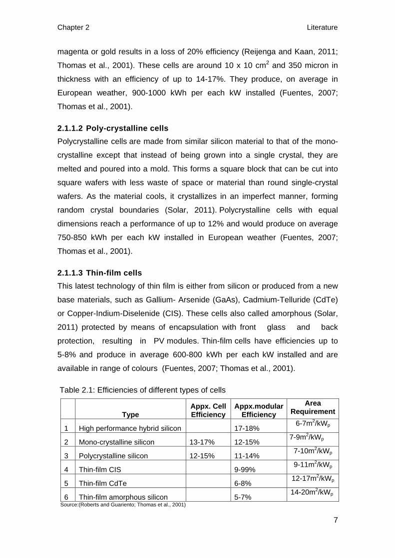
magenta or gold results in a loss of 20% efficiency (Reijenga and Kaan, 2011;
Thomas et al., 2001). These cells are around 10 x 10 cm2 and 350 micron in
thickness with an efficiency of up to 14-17%. They produce, on average in
European weather, 900-1000 kWh per each kW installed (Fuentes, 2007;
Thomas et al., 2001).
2.1.1.2 Poly-crystalline cells Polycrystalline cells are made from similar silicon material to that of the mono-
crystalline except that instead of being grown into a single crystal, they are
melted and poured into a mold. This forms a square block that can be cut into
square wafers with less waste of space or material than round single-crystal
wafers. As the material cools, it crystallizes in an imperfect manner, forming
random crystal boundaries (Solar, 2011). Polycrystalline cells with equal
dimensions reach a performance of up to 12% and would produce on average
750-850 kWh per each kW installed in European weather (Fuentes, 2007;
Thomas et al., 2001).
2.1.1.3 Thin-film cells This latest technology of thin film is either from silicon or produced from a new
base materials, such as Gallium- Arsenide (GaAs), Cadmium-Telluride (CdTe)
or Copper-Indium-Diselenide (CIS). These cells also called amorphous (Solar,
2011) protected by means of encapsulation with front glass and back
protection, resulting in PV modules. Thin-film cells have efficiencies up to
5-8% and produce in average 600-800 kWh per each kW installed and are
available in range of colours (Fuentes, 2007; Thomas et al., 2001).
Table 2.1: Efficiencies of different types of cells
Type Appx. Cell Efficiency
Appx.modular Efficiency
Area Requirement
1 High performance hybrid silicon 17-18% 6-7m2/kWp
2 Mono-crystalline silicon 13-17% 12-15% 7-9m2/kWp
3 Polycrystalline silicon 12-15% 11-14% 7-10m2/kWp
4 Thin-film CIS 9-99% 9-11m2/kWp
5 Thin-film CdTe 6-8% 12-17m2/kWp
6 Thin-film amorphous silicon 5-7% 14-20m2/kWp
Source:(Roberts and Guariento; Thomas et al., 2001)

Literature Chapter 2
8
Besides the above mentioned, there are a wide range of new PV technologies
being researched and developed in the pursuit of higher performance. HIT
(heterojunction with intrinsic thin-layer) is a hybrid construction of a crystalline
and thin-film silicon cell. Amorphous silicon is coated onto both front and rear
faces of a monocrystalline silicon wafer. These cells are more efficient
compared to monocrystalline silicon and have less degradation of efficiency
with increase in operating temperature. This technology is used in Vauxhall
transport interchange (fig 2.2), London UK which is excellent showcase for PV
integration (Roberts and Guariento).
Vauxhall transport interchange
is a good example of the
integration of HIT P. The PV
modules are incorporated in the
sloping sections (forks) of the
canopy at an angle of 20° to the
horizontal and 25° west of
south-facing. The canopy which
takes the form of a sculptural
ribbon running the length of the
bus station provides shelter
from rain and wind. Each fork
carries 4sub-arrays of 21 modules, which are connected back to the PV distribution
board. The PV units replace the stainless steel cladding panels of the top portion of
the canopy. The wireways, trunking and junction boxes are located underneath the
FIG 2.1: Types of photovoltaic cells
credit: http://www.pvsolarchina.com/
FIG 2.2: Vauxhall transport interchange Credit: (Roberts and Guariento)
Chapter 2 Literature
9
waterproof membrane, in the void of the canopy structure. Each fork is provided with a
walkway for further maintenance and replacement of the solar arrays (Sohie, 2003;
EST, 2006).
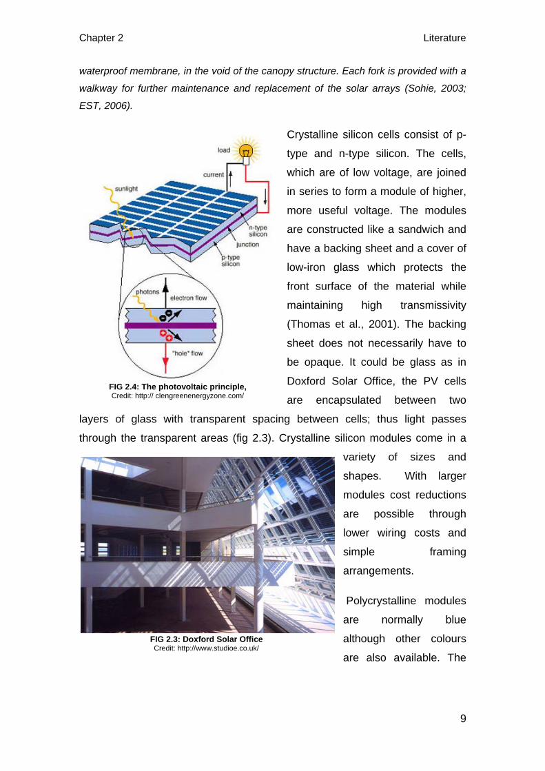
Crystalline silicon cells consist of p-
type and n-type silicon. The cells,
which are of low voltage, are joined
in series to form a module of higher,
more useful voltage. The modules
are constructed like a sandwich and
have a backing sheet and a cover of
low-iron glass which protects the
front surface of the material while
maintaining high transmissivity
(Thomas et al., 2001). The backing
sheet does not necessarily have to
be opaque. It could be glass as in
Doxford Solar Office, the PV cells
are encapsulated between two
layers of glass with transparent spacing between cells; thus light passes
through the transparent areas (fig 2.3). Crystalline silicon modules come in a
variety of sizes and
shapes. With larger
modules cost reductions
are possible through
lower wiring costs and
simple framing
arrangements.
Polycrystalline modules
are normally blue
although other colours
are also available. The
FIG 2.3: Doxford Solar Office Credit: http://www.studioe.co.uk/
FIG 2.4: The photovoltaic principle, Credit: http:// clengreenenergyzone.com/

Literature Chapter 2
10
appearance of thin-film cells is uniform with a dark matt surface with colours
ranging from grey, brown and black (Reijenga and Kaan, 2011; Thomas et al.,
2001).
PVs (Thomas et al., 2001; Fthenakis et al., 2008) have longer life span of more
than 20 yrs with rated output of at least 80% and energy payback period for the
production is 5 yrs. They have the significant advantages of reducing emissions
which is very important from environmental perspective. In general for the
manufacturing processes for crystalline silicon and amorphous silicon there are
no environmental issues which raise concern. Some reservations have been
expressed about the environmental impact of new materials, particularly
cadmium telluride. However, the production process can be designed so that
cadmium is not emitted and manufacturers are actively developing recycling
techniques to avoid disposal problems (Thomas et al., 2001). Overall, all PV
technologies generate far less life-cycle air emissions per GWh than
conventional fossil-fuel based electricity generation technologies and at least
89% of air emissions associated with electricity generation could be prevented
if electricity from photovoltaic system displaces electricity from the grid
(Fthenakis et al., 2008).
The output from the PV array will depend on (Thomas et al., 2001):
• The daily variation due to the rotation of the earth and the seasonal one
due to the orientation of the earth’s axis ad the movement of the earth
about the sun
• Location, (the solar radiation available at the site)
• Tilt.
• Azimuth, (orientation with respect to due south)
• Shadowing
• Temperature, (The drop in performance is more marked for crystalline
silicon than amorphous silicon. Designs for building-integrated PVs need
to consider this from the very beginning in order to allow air to flow over
the backs of the modules to maintain high performance.)
Chapter 2 Literature
11
2.1.2 PV modules
PV cells are arranged together to form modules. The modules are designed
for outdoor conditions, so they are able to be part of the building skin.
However, different encapsulation technologies result in a range of PV panels
having different performances as a constructive element like glass-plastic or
g lass-g lass back sheet. Standard modules have an aluminium frame.
Modules without a frame, also called "laminates", are more commonly used for
building integration (Fuentes, 2007).
2.2 Solar Thermal Collectors
Solar thermal collector is a device which absorbs the incoming solar radiation,
converts it into heat, and transfers this heat to a fluid (usually air, water, or oil)
flowing through the collector. The solar energy thus collected is carried from the
circulating fluid either directly to the water or space conditioning equipment or
to a insulated storage tank from which hot water can be drawn for use even
during nights and in cloudy days (Kalogirou, 2004; Probst, 2009).
Maria Probest (2009) in here Ph.D thesis have described this STC system as
active. Energy when collected on surfaces optimized for heat collection called
absorbers which are placed on the outside of the building envelop and
transported by a medium either directly to the place of use, or to a storage to
be used when needed is commonly known as active system. According to the
medium used, active systems are mainly of two types: air collectors and water
collectors.
2.2.1 Air-based collector systems
These are primarily designed for preheating ventilation air or for space heating.
When used for preheating ventilation air, the collectors are often placed on the
façade close to where the fresh air enters the building. This results in short
ducts, as well as higher efficiency during the space-heating period (favourable
inclination at low solar angles). An air-based collector system is usually
designed to make use of the building structure for heat storage, although
separate storage elements are sometimes used. The use of a central air-
handling system or a double-envelop façade also makes it suitable to use air-
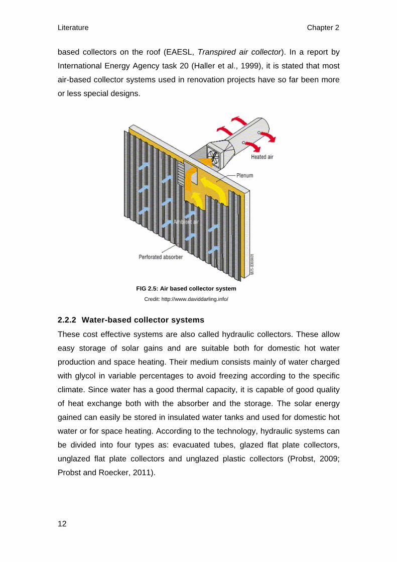
Literature Chapter 2
12
based collectors on the roof (EAESL, Transpired air collector). In a report by
International Energy Agency task 20 (Haller et al., 1999), it is stated that most
air-based collector systems used in renovation projects have so far been more
or less special designs.
2.2.2 Water-based collector systems
These cost effective systems are also called hydraulic collectors. These allow
easy storage of solar gains and are suitable both for domestic hot water
production and space heating. Their medium consists mainly of water charged
with glycol in variable percentages to avoid freezing according to the specific
climate. Since water has a good thermal capacity, it is capable of good quality
of heat exchange both with the absorber and the storage. The solar energy
gained can easily be stored in insulated water tanks and used for domestic hot
water or for space heating. According to the technology, hydraulic systems can
be divided into four types as: evacuated tubes, glazed flat plate collectors,
unglazed flat plate collectors and unglazed plastic collectors (Probst, 2009;
Probst and Roecker, 2011).
FIG 2.5: Air based collector system Credit: http://www.daviddarling.info/
Chapter 2 Literature
13
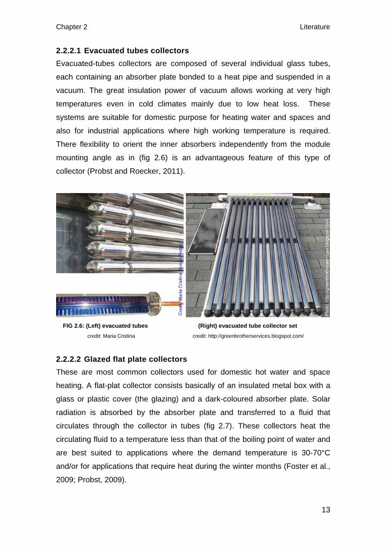
2.2.2.1 Evacuated tubes collectors Evacuated-tubes collectors are composed of several individual glass tubes,
each containing an absorber plate bonded to a heat pipe and suspended in a
vacuum. The great insulation power of vacuum allows working at very high
temperatures even in cold climates mainly due to low heat loss. These
systems are suitable for domestic purpose for heating water and spaces and
also for industrial applications where high working temperature is required.
There flexibility to orient the inner absorbers independently from the module
mounting angle as in (fig 2.6) is an advantageous feature of this type of
collector (Probst and Roecker, 2011).
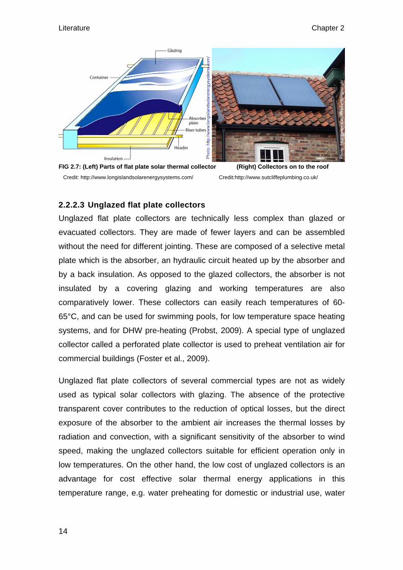
2.2.2.2 Glazed flat plate collectors These are most common collectors used for domestic hot water and space
heating. A flat-plat collector consists basically of an insulated metal box with a
glass or plastic cover (the glazing) and a dark-coloured absorber plate. Solar
radiation is absorbed by the absorber plate and transferred to a fluid that
circulates through the collector in tubes (fig 2.7). These collectors heat the
circulating fluid to a temperature less than that of the boiling point of water and
are best suited to applications where the demand temperature is 30-70°C
and/or for applications that require heat during the winter months (Foster et al.,
2009; Probst, 2009).
FIG 2.6: (Left) evacuated tubes (Right) evacuated tube collector set credit: Maria Cristina credit: http://greenbrotherservices.blogspot.com/
Literature Chapter 2
14
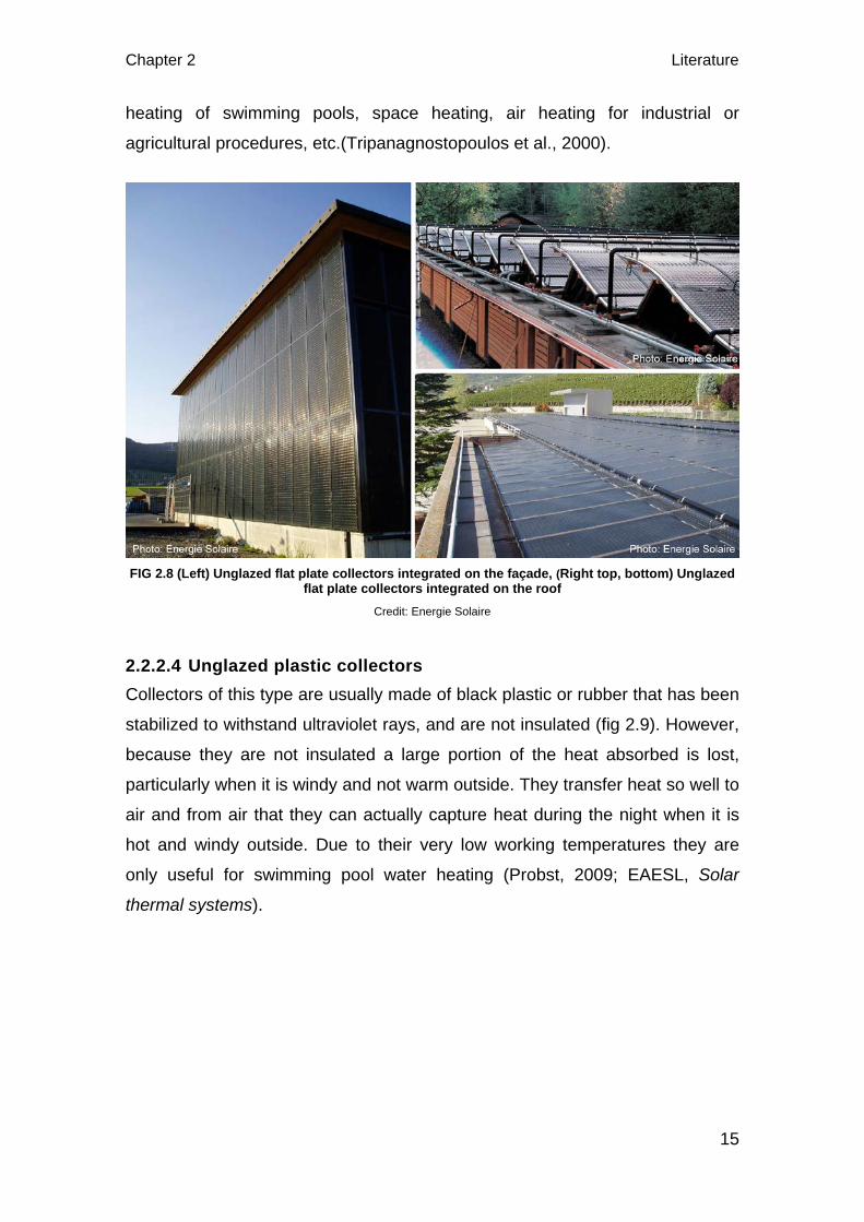
2.2.2.3 Unglazed flat plate collectors Unglazed flat plate collectors are technically less complex than glazed or
evacuated collectors. They are made of fewer layers and can be assembled
without the need for different jointing. These are composed of a selective metal
plate which is the absorber, an hydraulic circuit heated up by the absorber and
by a back insulation. As opposed to the glazed collectors, the absorber is not
insulated by a covering glazing and working temperatures are also
comparatively lower. These collectors can easily reach temperatures of 60-
65°C, and can be used for swimming pools, for low temperature space heating
systems, and for DHW pre-heating (Probst, 2009). A special type of unglazed
collector called a perforated plate collector is used to preheat ventilation air for
commercial buildings (Foster et al., 2009).
Unglazed flat plate collectors of several commercial types are not as widely
used as typical solar collectors with glazing. The absence of the protective
transparent cover contributes to the reduction of optical losses, but the direct
exposure of the absorber to the ambient air increases the thermal losses by
radiation and convection, with a significant sensitivity of the absorber to wind
speed, making the unglazed collectors suitable for efficient operation only in
low temperatures. On the other hand, the low cost of unglazed collectors is an
advantage for cost effective solar thermal energy applications in this
temperature range, e.g. water preheating for domestic or industrial use, water
FIG 2.7: (Left) Parts of flat plate solar thermal collector (Right) Collectors on to the roof Credit: http://www.longislandsolarenergysystems.com/ Credit:http://www.sutcliffeplumbing.co.uk/
Chapter 2 Literature
15
heating of swimming pools, space heating, air heating for industrial or
agricultural procedures, etc.(Tripanagnostopoulos et al., 2000).
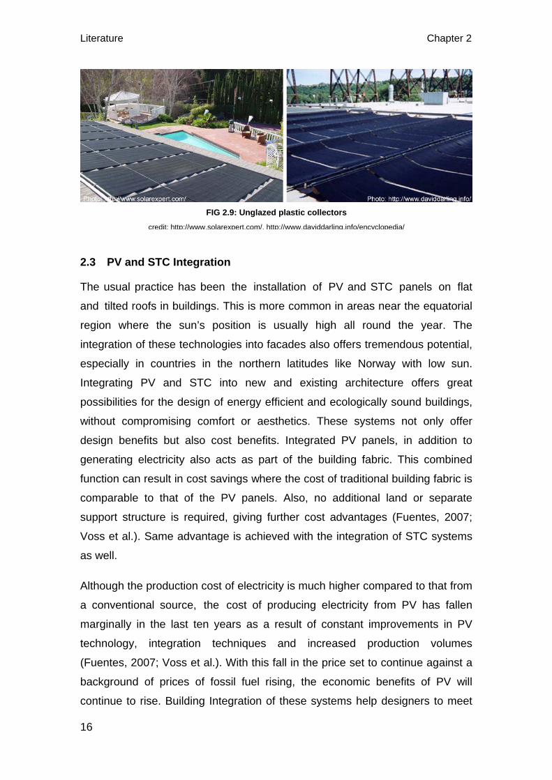
2.2.2.4 Unglazed plastic collectors Collectors of this type are usually made of black plastic or rubber that has been
stabilized to withstand ultraviolet rays, and are not insulated (fig 2.9). However,
because they are not insulated a large portion of the heat absorbed is lost,
particularly when it is windy and not warm outside. They transfer heat so well to
air and from air that they can actually capture heat during the night when it is
hot and windy outside. Due to their very low working temperatures they are
only useful for swimming pool water heating (Probst, 2009; EAESL, Solar
thermal systems).
FIG 2.8 (Left) Unglazed flat plate collectors integrated on the façade, (Right top, bottom) Unglazed flat plate collectors integrated on the roof
Credit: Energie Solaire
Literature Chapter 2
16
2.3 PV and STC Integration
The usual practice has been the installation of PV and STC panels on flat
and tilted roofs in buildings. This is more common in areas near the equatorial
region where the sun’s position is usually high all round the year. The
integration of these technologies into facades also offers tremendous potential,
especially in countries in the northern latitudes like Norway with low sun.
Integrating PV and STC into new and existing architecture offers great
possibilities for the design of energy efficient and ecologically sound buildings,
without compromising comfort or aesthetics. These systems not only offer
design benefits but also cost benefits. Integrated PV panels, in addition to
generating electricity also acts as part of the building fabric. This combined
function can result in cost savings where the cost of traditional building fabric is
comparable to that of the PV panels. Also, no additional land or separate
support structure is required, giving further cost advantages (Fuentes, 2007;
Voss et al.). Same advantage is achieved with the integration of STC systems
as well.
Although the production cost of electricity is much higher compared to that from
a conventional source, the cost of producing electricity from PV has fallen
marginally in the last ten years as a result of constant improvements in PV
technology, integration techniques and increased production volumes
(Fuentes, 2007; Voss et al.). With this fall in the price set to continue against a
background of prices of fossil fuel rising, the economic benefits of PV will
continue to rise. Building Integration of these systems help designers to meet
FIG 2.9: Unglazed plastic collectors credit: http://www.solarexpert.com/, http://www.daviddarling.info/encyclopedia/
Chapter 2 Literature
17
goals of sustainability and reduced emissions while maintaining or improving
comfort. The synergy between integrated PV or STC’s main functions of on-
site energy generation and forming part of the building fabric, along with
increasing cost competitiveness makes integration an especially attractive
option. (Fuentes, 2007).

Architectural integration and building integration Chapter 3
18
3 ARCHITECTURAL INTEGRATION AND BUILDING INTEGRATION
3.1 Building Integration
The PV and solar thermal collector systems when integrated in a building,
become part of the general building design and also often become general
building elements (Hestnes, 1999). From economical point of view, it is
necessary that the systems are integrated into the building envelop so that no
extra investments on the support structure is needed. These systems must
replace the conventional building elements in addition to their ability to produce
energy and serve dual function to reduce the total cost. Hence, the energy
systems in a building must be designed as an integral part of the whole; ie, a
‘holistic’ approach to building design should be approached. These systems
must be taken very early in the design phase and should not be treated as
separate elements that are added after the design or building is completed.
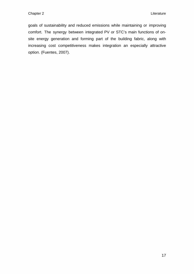
Example of the largest solar thermal project integration is seen in the “Solar
City”, housing development in the suburb Plan-les-Quates, Switzerland (fig
3.1). Integrating the systems on the roof was thought of right from the
conceptual design phase. These collectors cover the entire south facing part of
the roof replacing the traditional roofing materials, thereby reducing the total
cost of the project. In addition to energy production for space and water
heating, the aesthetics of the building is enhanced by the elegant curvature of
the roofs. In summer the excess energy production is sold to neighbouring
buildings (Hestnes, 1999).
The terms component integrated and building integrated photovoltaics (BIPV)
refers to the concept of integrating photovoltaic elements into the building
envelope, establishing a symbiotic relationship between the architectural
design, functional properties and economic regenerative energy conversion
(Odersun, 2011). The photovoltaic modules thus replace conventional
construction materials, taking over the function that these would otherwise
perform. Although this idea is not new, it is not widely harnessed due to the
extensive planning and architectural challenges currently involved.
Chapter 3 Architectural integration and building integration
19
In principle, BIPV can be used in all parts of the building envelope. Although
roof surfaces are the preferred area for installing PV elements due to their
advantageous irradiation values, façades also offer enormous potential
specially in Nordic region where the angle of the sun is low all throughout the
year. The ratio of façade surface area to roof surface area increases along with
the building height. In addition, the available roof area is often reduced due to
the installation of facilities and superstructures, which means that BIPV façades
are of particular value in high-density urban centers. Besides, with the
availability of thin-film PV, integration into the facades has become even more
relevant (Odersun, 2011).
In building or architectural integration, besides producing energy; the active
solar elements have to play the same role as the traditional wall, windows or
roof cladding elements they replace. Roberts and Guariento in their handbook
of BIPV have said that the requirements that must be addressed by building
integrated active solar systems are colour, image, size, weather-tightness, wind
loading, durability and maintenance, safety during construction and in use (fire,
electrical, stability) and cost.
FIG 3.1: Elegant use of solar thermal collectors on the curved roof of ‘Solar City’, housing development in the suburb Plan-les-Quates, Switzerland
credit: (Hestnes, 1999)
Architectural integration and building integration Chapter 3
20
Building integration concerns the physical integration of a PV or STC system
into a building, with the emphasis of overall impression they give to the
building. For the architect, the aesthetic aspect, rather than the physical
integration, is the main reason for talking about building integration. The
optimal situation is a physically and aesthetically well-integrated system. In fact,
many examples of physical integration show a lack of aesthetic integration.
Visual analysis of solar systems in buildings shows that the look of a poorly
designed building does not improve, simple by adding a well-designed system.
On the other hand, a well-designed building with a nicely integrated solar
system will be accepted by everybody (Reijenga and Kaan, 2011).
3.2 Difference between architectural integration and building integration
The answer to this is to look for different types of integration. It is usually
possible to do architectural integration, ie, integrate the systems in an
architecturally good way so that the aesthetics of the building is enhanced.
However, it may always not be that easy to do building integration.
Most of the times, the PV or collector systems on the buildings are either
architecturally integrated or building integrated or both. These systems doesn’t
have to be building integrated to achieve architectural integration. It can be
further said that building integration is architectural integration but all
architectural integration is not building integration. When the process of
integration enhances the architectural quality of the building, it is called
architectural integration. So, in a building integrated PV roof, the roof may be
specially manufactured with PV already fixed as the external part of the roof. In
case of architecturally integrated PV roof; PV modules can be laid as normal
roofing element with normal construction techniques. In both the cases, the
integration may add on to the aesthetics of the roof and the whole building and
hence called architectural integration. Integration also doesn’t mean that the PV
and STC systems are used in such a way that they are not recognizable. It isn’t
necessarily wonderful or important that the integrated PV and collector system
is ‘hidden’ and not shown.
Chapter 3 Architectural integration and building integration
21
In practice, energy output of PV and STC systems may have to be
compromised over architectural integration. Which means, in an approach to
use these systems in such a way that the building’s architectural expression is
enhanced; they may not be located in the best position, direction and
orientation. It is necessary to compromise but the best thing would be not to
compromise. Due to practical reasons, there are compromises. We must be
more innovative and creative enough to tackle this (Hestnes, 2012).
3.3 Does architectural integration really boost aesthetics of a building?
When the PV and STC systems are part of the architectural composition, they
are architecturally integrated. Architectural integration is an important topic in
an old building compared to a new one if the integration adds value to the
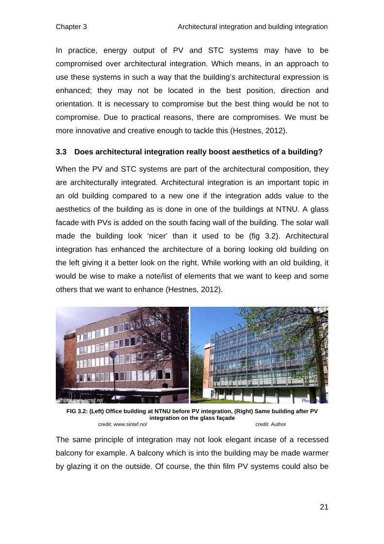
aesthetics of the building as is done in one of the buildings at NTNU. A glass
facade with PVs is added on the south facing wall of the building. The solar wall
made the building look ‘nicer’ than it used to be (fig 3.2). Architectural
integration has enhanced the architecture of a boring looking old building on
the left giving it a better look on the right. While working with an old building, it
would be wise to make a note/list of elements that we want to keep and some
others that we want to enhance (Hestnes, 2012).
The same principle of integration may not look elegant incase of a recessed
balcony for example. A balcony which is into the building may be made warmer
by glazing it on the outside. Of course, the thin film PV systems could also be
FIG 3.2: (Left) Office building at NTNU before PV integration, (Right) Same building after PV integration on the glass façade
credit: www.sintef.no/ credit: Author
Architectural integration and building integration Chapter 3
22
integrated into the glass. However, the consequence is that the façade
becomes two dimensional, plain and boring.
If a new building integrating PV and solar thermal collector systems is to be
designed, the concept is usually driven by these systems and so, the final
result may turn out high-tech. However, in case of an old building, the design,
layout and use of these active systems is actually driven by the architecture
and colour of the building.
3.4 What are the challenges between integration into existing and new building?
Existing or historic buildings, like new buildings, offer a broad range of
possibilities for PV and STC system integration. However, installations on
existing buildings unavoidably tend to be more fragmented than on new
buildings, since they have to comply with an existing situation. As standardised
products are often not applicable, the situation calls for innovative approaches
with custom made products (Hermannsdorfer and Rub, 2005). It is always not
an easy task to make integration in an existing building due to various
practicalities. Integration task will have to be planned according to the situation
observed on site which varies from building to building.
In case of historically important building, sometimes the PV and thermal
collector systems might have to be integrated somewhere else other then the
building itself, if there are regulations not to make interventions. In some cases
little intervention is allowed like the church in Carlow, Germany (fig 7.1). The
church was equipped with PV in the course of roof repairs. The polycrystalline
module was produced to match the existing roof tiles in shape and colour; one
photovoltaic module replaced six roof tiles. The PVs are integrated into only a
small part of the roof replacing the normal roofing material. Thus the historical
appearance of the church was maintained as stipulated by the monument
protection authority (Hermannsdorfer and Rub, 2005).
In case of new buildings, integration of PV or STC systems is conceived from
very early stage of the design. As such, these systems will be an integral part
of the design concept; forms may be derived accordingly and material use
Chapter 3 Architectural integration and building integration
23
determined as well. The solar cells are interesting as a material when
integrated in the architectural concept. The possibilities of working with PVs or
STC as a part of the concept have varied. This depends much on when these
systems are introduced in the project (Lundgren and Torstensson, 2004). In
this way, integration in new buildings looks comparatively easier than the
existing ones as these solar systems will be used accordingly after appropriate
design have been developed.
3.5 Good Integration
PV and STC systems that are architecturally pleasing within the context of the
building, good material and colour composition, that adapt well to overall
modularity, the visual aspect of the grid which is in harmony with the building
and creates a satisfactory composition will result in good integration and
renders high architectural quality (Roberts and Guariento). Further, these
systems that are appropriate to the context of the building and the integration of
which is well designed and their use has generated an innovative concept will
often make the architectural integration rich and successful.
3.6 Integration of PV and STC modules in buildings
For architects, the application of PV and STC systems in buildings must be part
of a holistic approach. A high-quality of these solar systems can provide a
substantial part of the building’s energy needs if the building has been
designed in the right way. By holistic approach, integrating these systems does
not only mean replacing a conventional building material, but also aesthetically
integrating it into the design which is called architectural integration. The
integration also takes over other functions of the building’s skin. Mounted on a
sloped roof for instance, profile systems mean that PV or STC modules can be
part of the watertight skin. A distinction can be made between literal integration
of these systems in the building skin as cladding elements or integrated into the
roof or as building components like awnings, shading devices etc. (Reijenga
and Kaan, 2011).
The aim of architectural and building integration of these systems into buildings
is to reduce the requirement for land and the costs, in addition to aesthetics
Architectural integration and building integration Chapter 3
24
that is generated by the process. This could be the cost of support construction
and the cost of building elements, such as tiles and cladding elements. It is
evident that PV and STC systems integrated into buildings give a more elegant
look and is more efficient to integrate these systems when constructing the
building, rather than mounting it afterwards. Usually there are three locations
for integrating these systems into buildings. They are the roofs, facades and
building components like balcony railings, sunshades and sunscreens(Reijenga
and Kaan, 2011).
3.7 Integration Method
Both PV and STC systems can be incorporated into buildings by either
superimposition - where the system is attached over the existing building
envelope, or integration - where the system forms a part of the building
envelope (Fuentes, 2007).
3.7.1 Superimposed
This is a simple method well suited in case of existing buildings. The solar
modules are mounted on a structure; for eg: roof, on the building envelope and
in parallel with them. There is no savings in substituting elements as the
materials underneath the solar modules are not replaced (Fuentes, 2007). With
superimposition, architectural integration can still be achieved as the buildings
can be made elegant. If this is the case, it may also be called architectural
integration but is certainly not building integration. However, the scope of the
thesis is to emphasize more on architectural integration that is also building
integration.
3.7.2 Integrated
The PV and STC systems are used both as an architectural element as well as
a means of energy generation. This method is most likely to be suitable for new
buildings. The traditional constructive elements are substituted for PV and STC
materials. Savings are possible where the cost of the substituted elements is
below that of the traditional elements. It offers a pleasant and clean
appearance (Fuentes, 2007). The most common integration types and
techniques are discussed in the following two chapters.
Chapter 4 Integration of Photovoltaics
25
4 INTEGRATION OF PHOTOVOLTAICS
With the discovery of photovoltaics, the building’s skin is found to have the
capacity to produce energy as well. Photovoltaic modules are in most cases
still considered to be technical devices that need to be adjusted to the building
skin, despite the fact that a variety of products that convert them into building
components have been developed lately. However, in case the solar module
becomes part of the building skin, it gains multiple functions and requires
aesthetical integration into the overall design concept (Farkas, Facade
Integration Typologies of Photovoltaics). Both roofs and facades can be
explored for the architectural potential of integration. Inclined and pitched roofs
are equally visible as facades are, and hence can provide architects with both
opportunities and challenges for architectural integration. Any part of the roof or
external walls that is well-exposed to sunlight e.g. skylights, claddings,
windows, external shading devices and railings can be used for PV integration.
On non-exposed or other surfaces where PVs are not considered integrating or
are not suitable, the use of dummy1 elements could be the possible option.
With this uniformity can be achieved.
Integration of PV into buildings have the following advantages (Reijenga and
Kaan, 2011; Voss et al.):
• Part of building is used for PV installation and so additional land is not
required. This is particularly significant in the densely populated areas in the
cities.
• The cost of the PV wall or roof can be offset against the cost of the building
element it replaces.
• Power is generated on site and replaces electricity that would otherwise be
purchased at commercial rates and avoids distribution losses.
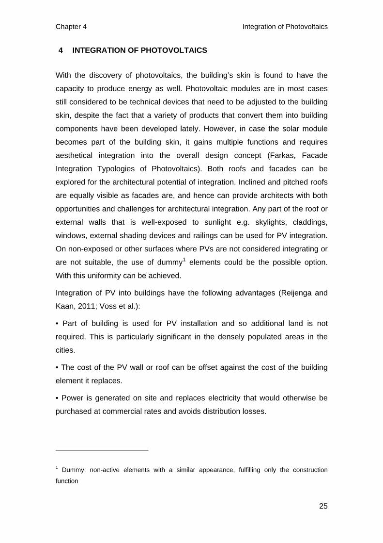
1 Dummy: non-active elements with a similar appearance, fulfilling only the construction
function
Integration of Photovoltaics Chapter 4
26
• PV, if grid connected ensures security of supply and high cost of storage is
avoided.
• Architecturally elegant, well-integrated systems will increase market
acceptance.
4.1 Roof Integration of PV
A PV system can be integrated into the roof in several ways. One choice is for
the integrated system to be part of the external skin and therefore part of an
impermeable layer in the construction. The other type is that the PV is glued
onto insulation material. This type of warm roof construction system is very well
suited to renovating large flat roofs. Using PV modules as roof covering
reduces the amount of building materials needed, which is very favourable for a
sustainable building and can help to reduce costs. There are also many
products for small-scale use to suit the scale of the roof covering, for eg., PV
shingles and tiles. The small scale of these products makes them very
convenient for use in existing buildings. Transparent PV modules used as
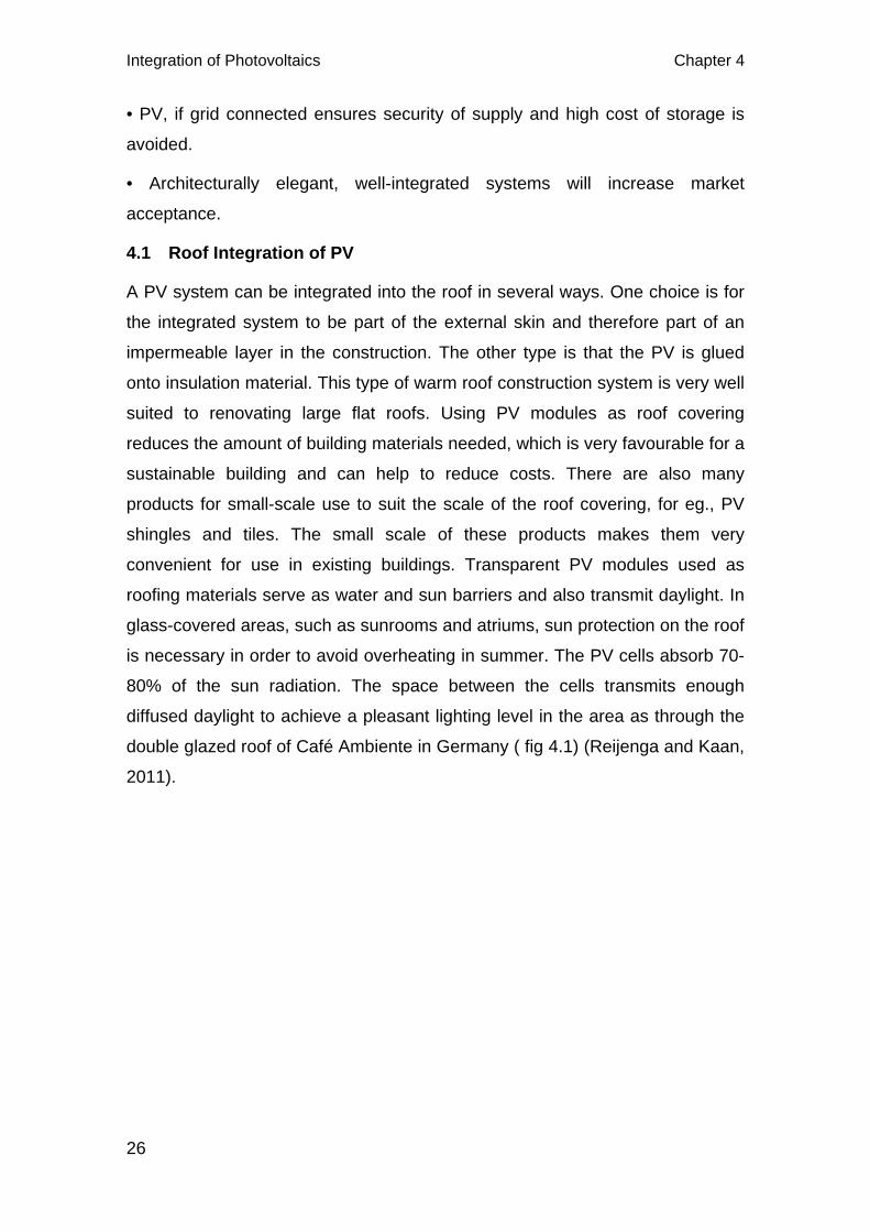
roofing materials serve as water and sun barriers and also transmit daylight. In
glass-covered areas, such as sunrooms and atriums, sun protection on the roof
is necessary in order to avoid overheating in summer. The PV cells absorb 70-
80% of the sun radiation. The space between the cells transmits enough
diffused daylight to achieve a pleasant lighting level in the area as through the
double glazed roof of Café Ambiente in Germany ( fig 4.1) (Reijenga and Kaan,
2011).
Chapter 4 Integration of Photovoltaics
27
PV cells convert sunlight into electricity (typical efficiencies of 6-18%) with the
remainder of the solar energy being converted into heat. At the project ‘Haus
de Zukunft’ in Linz (Austria), this residual heat is also used to warm the home.
An air cavity has been created underneath the PV modules, through which
warm air heated by the PVs above, is exhausted. The hybrid collector provides
warm air to the heating system in the home, which in this case, makes it a cost-
effective se of the collector.
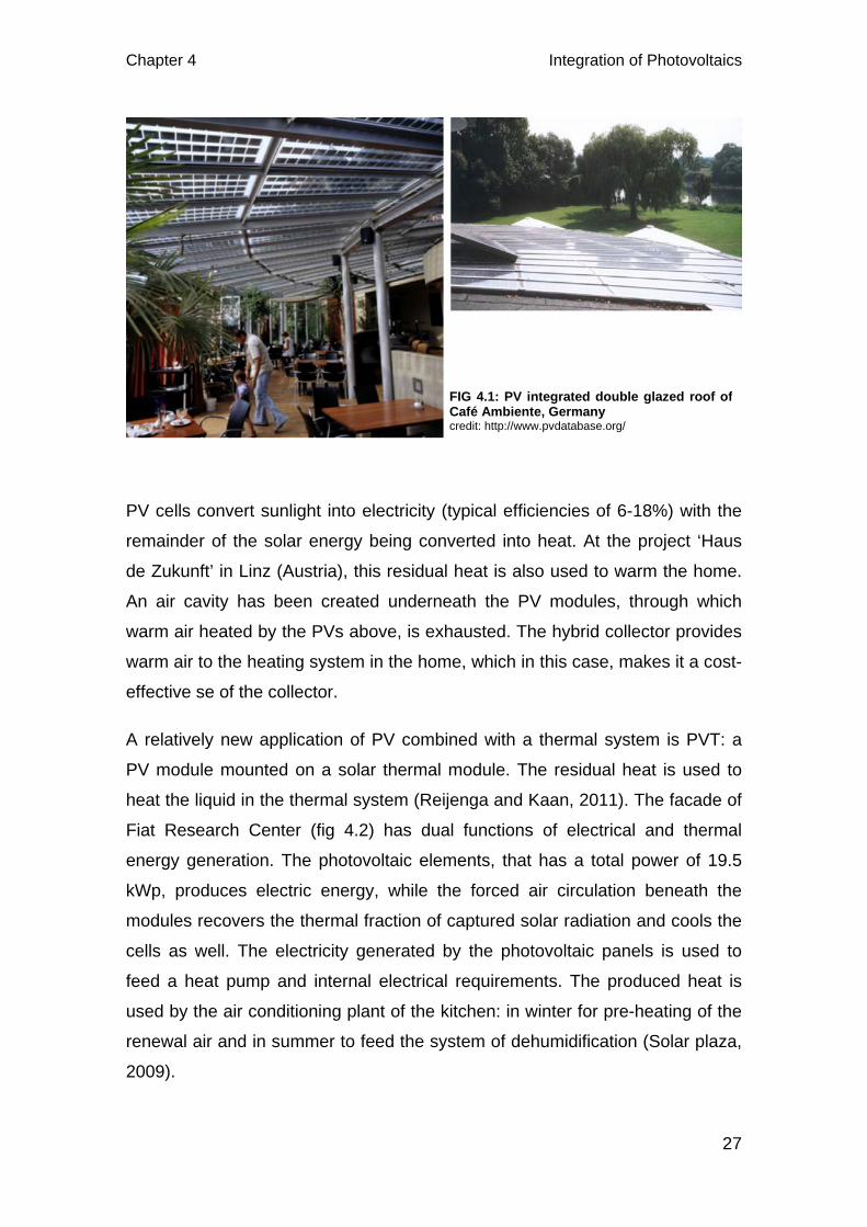
A relatively new application of PV combined with a thermal system is PVT: a
PV module mounted on a solar thermal module. The residual heat is used to
heat the liquid in the thermal system (Reijenga and Kaan, 2011). The facade of
Fiat Research Center (fig 4.2) has dual functions of electrical and thermal
energy generation. The photovoltaic elements, that has a total power of 19.5
kWp, produces electric energy, while the forced air circulation beneath the
modules recovers the thermal fraction of captured solar radiation and cools the
cells as well. The electricity generated by the photovoltaic panels is used to
feed a heat pump and internal electrical requirements. The produced heat is
used by the air conditioning plant of the kitchen: in winter for pre-heating of the
renewal air and in summer to feed the system of dehumidification (Solar plaza,
2009).
FIG 4.1: PV integrated double glazed roof of Café Ambiente, Germany credit: http://www.pvdatabase.org/
Integration of Photovoltaics Chapter 4
28
4.1.1 PVs on flat roof
PVs laid horizontally on the flat roofs are normally not visible from the ground
and hence the significance of aesthetic part of integration can be less.
However, from efficiency view point, mono and poly-crystalline PV systems
produce the most energy when their angle is optimised to that of the sun. So,
usually it may not be a good idea to lay these cells horizontally on the flat roofs
both from aesthetic point of integration and energy yield. Unlike to this, thin
films work equally well even when laid horizontally on flat surfaces proving to
be the best options for integrating into flat roofs. However, installing the PV
systems in an angled position on the flat roof may not play a positive role in
adding to the aesthetics of the building and hence may not be termed as
architectural integration.
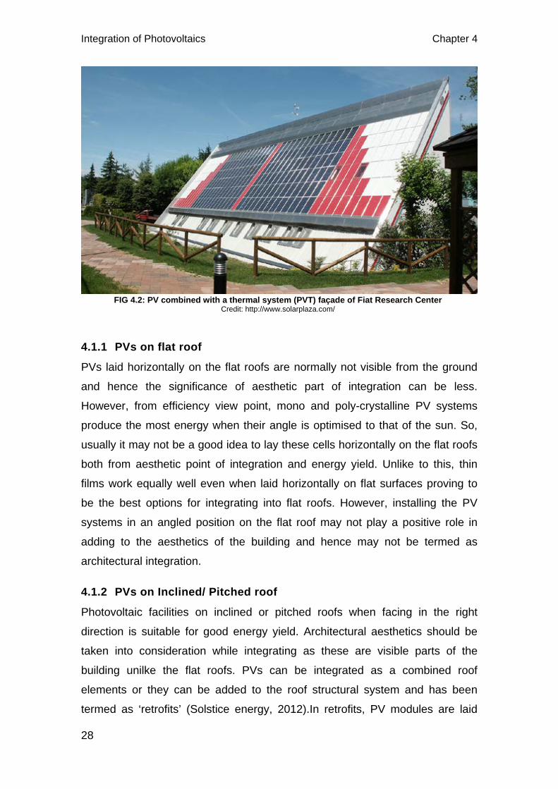
4.1.2 PVs on Inclined/ Pitched roof
Photovoltaic facilities on inclined or pitched roofs when facing in the right
direction is suitable for good energy yield. Architectural aesthetics should be
taken into consideration while integrating as these are visible parts of the
building unilke the flat roofs. PVs can be integrated as a combined roof
elements or they can be added to the roof structural system and has been
termed as ‘retrofits’ (Solstice energy, 2012).In retrofits, PV modules are laid
FIG 4.2: PV combined with a thermal system (PVT) façade of Fiat Research Center Credit: http://www.solarplaza.com/
Chapter 4 Integration of Photovoltaics
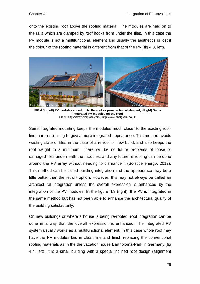
29
onto the existing roof above the roofing material. The modules are held on to
the rails which are clamped by roof hooks from under the tiles. In this case the
PV module is not a multifunctional element and usually the aesthetics is lost if
the colour of the roofing material is different from that of the PV (fig 4.3, left).
Semi-integrated mounting keeps the modules much closer to the existing roof-
line than retro-fitting to give a more integrated appearance. This method avoids
wasting slate or tiles in the case of a re-roof or new build, and also keeps the
roof weight to a minimum. There will be no future problems of loose or
damaged tiles underneath the modules, and any future re-roofing can be done
around the PV array without needing to dismantle it (Solstice energy, 2012).
This method can be called building integration and the appearance may be a
little better than the retrofit option. However, this may not always be called an
architectural integration unless the overall expression is enhanced by the
integration of the PV modules. In the figure 4.3 (right), the PV is integrated in
the same method but has not been able to enhance the architectural quality of
the building satisfactorily.
On new buildings or where a house is being re-roofed, roof integration can be
done in a way that the overall expression is enhanced. The integrated PV
system usually works as a multifunctional element. In this case whole roof may
have the PV modules laid in clean line and finish replacing the conventional
roofing materials as in the the vacation house Bartholomä-Park in Germany (fig
4.4, left). It is a small building with a special inclined roof design (alignment
FIG 4.3: (Left) PV modules added on to the roof as pure technical element, (Right) Semi-integrated PV modules on the Roof
Credit: http://www.solarplaza.com/, http://www.energyenv.co.uk/
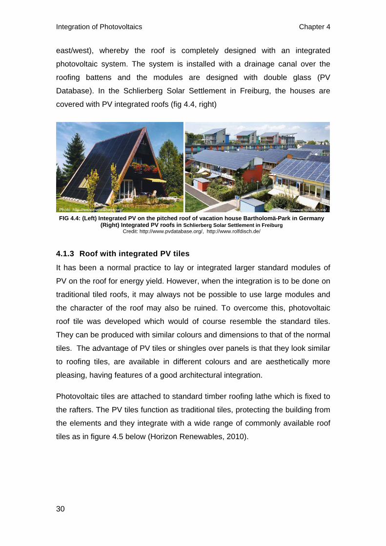
Integration of Photovoltaics Chapter 4
30
east/west), whereby the roof is completely designed with an integrated
photovoltaic system. The system is installed with a drainage canal over the
roofing battens and the modules are designed with double glass (PV
Database). In the Schlierberg Solar Settlement in Freiburg, the houses are
covered with PV integrated roofs (fig 4.4, right)
4.1.3 Roof with integrated PV tiles
It has been a normal practice to lay or integrated larger standard modules of
PV on the roof for energy yield. However, when the integration is to be done on
traditional tiled roofs, it may always not be possible to use large modules and
the character of the roof may also be ruined. To overcome this, photovoltaic
roof tile was developed which would of course resemble the standard tiles.
They can be produced with similar colours and dimensions to that of the normal
tiles. The advantage of PV tiles or shingles over panels is that they look similar
to roofing tiles, are available in different colours and are aesthetically more
pleasing, having features of a good architectural integration.
Photovoltaic tiles are attached to standard timber roofing lathe which is fixed to
the rafters. The PV tiles function as traditional tiles, protecting the building from
the elements and they integrate with a wide range of commonly available roof
tiles as in figure 4.5 below (Horizon Renewables, 2010).
FIG 4.4: (Left) Integrated PV on the pitched roof of vacation house Bartholomä-Park in Germany (Right) Integrated PV roofs in Schlierberg Solar Settlement in Freiburg
Credit: http://www.pvdatabase.org/, http://www.rolfdisch.de/
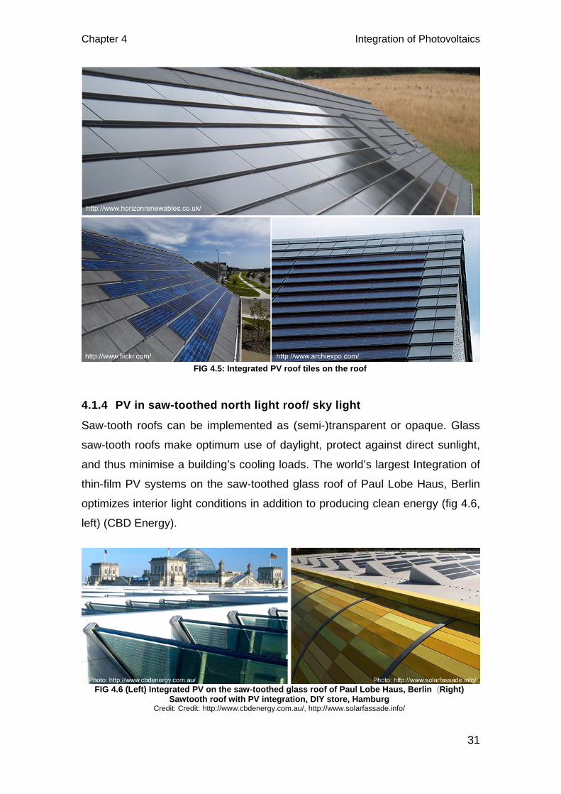
Chapter 4 Integration of Photovoltaics
31
4.1.4 PV in saw-toothed north light roof/ sky light
Saw-tooth roofs can be implemented as (semi-)transparent or opaque. Glass
saw-tooth roofs make optimum use of daylight, protect against direct sunlight,
and thus minimise a building’s cooling loads. The world’s largest Integration of
thin-film PV systems on the saw-toothed glass roof of Paul Lobe Haus, Berlin
optimizes interior light conditions in addition to producing clean energy (fig 4.6,
left) (CBD Energy).
FIG 4.5: Integrated PV roof tiles on the roof
FIG 4.6 (Left) Integrated PV on the saw-toothed glass roof of Paul Lobe Haus, Berlin (Right) Sawtooth roof with PV integration, DIY store, Hamburg
Credit: Credit: http://www.cbdenergy.com.au/, http://www.solarfassade.info/

Integration of Photovoltaics Chapter 4
32
4.1.5 PVs on Curved roof/wall
The flexibility with the integration of PV is further emphasized by the fact that
PV modules can also be mounted on curved load-bearing surfaces. Arched
surfaces and roofs are equally suited for use with PV systems. This allows
added freedom of design involving PV integration. The BP solar Showcase in
Birmingham, UK is a good example of PV integration on curved roof (fig 4.7).
It was designed as a prototype building, showing the integration of PV cells into
the energy efficient domestic and commercial buildings. The use of PVs was
the driving force behind the construction of this pavilion, and the embracing
architectural concept and expression of the solar paths. The solar units are
inherently part of the south-facing solar wall/roof cladding system. The wall is
curved and angled to optimise absorption of the solar energy and maintain a
nearly constant electrical output, whilst also shading the east and west vertical
walls to protect against excessive solar gain. The mono-crystalline PV
installation with a peak power generation of 15kW is used to operate
ventilation, lighting and electrical equipment. The excess power is fed to the
national grid and imported during the night(Sohie).
FIG 4.7: PV integration on the curved roof of BP solar Showcase in Birmingham
Credit: http://www.solartechnologies.co.uk/
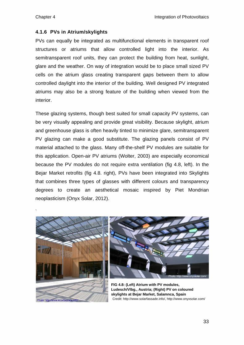
Chapter 4 Integration of Photovoltaics
33
4.1.6 PVs in Atrium/skylights
PVs can equally be integrated as multifunctional elements in transparent roof
structures or atriums that allow controlled light into the interior. As
semitransparent roof units, they can protect the building from heat, sunlight,
glare and the weather. On way of integration would be to place small sized PV
cells on the atrium glass creating transparent gaps between them to allow
controlled daylight into the interior of the building. Well designed PV integrated
atriums may also be a strong feature of the building when viewed from the
interior.
These glazing systems, though best suited for small capacity PV systems, can
be very visually appealing and provide great visibility. Because skylight, atrium
and greenhouse glass is often heavily tinted to minimize glare, semitransparent
PV glazing can make a good substitute. The glazing panels consist of PV
material attached to the glass. Many off-the-shelf PV modules are suitable for
this application. Open-air PV atriums (Wolter, 2003) are especially economical
because the PV modules do not require extra ventilation (fig 4.8, left). In the
Bejar Market retrofits (fig 4.8. right), PVs have been integrated into Skylights
that combines three types of glasses with different colours and transparency
degrees to create an aesthetical mosaic inspired by Piet Mondrian
neoplasticism (Onyx Solar, 2012).
`
FIG 4.8: (Left) Atrium with PV modules, Ludesch/Vlbg., Austria; (Right) PV on coloured skylights at Bejar Market, Salamnca, Spain Credit: http://www.solarfassade.info/, http://www.onyxsolar.com/
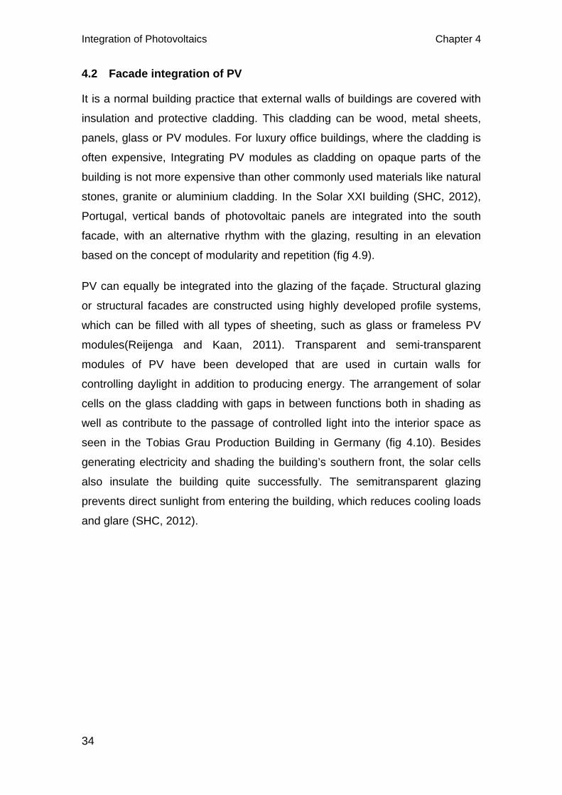
Integration of Photovoltaics Chapter 4
34
4.2 Facade integration of PV
It is a normal building practice that external walls of buildings are covered with
insulation and protective cladding. This cladding can be wood, metal sheets,
panels, glass or PV modules. For luxury office buildings, where the cladding is
often expensive, Integrating PV modules as cladding on opaque parts of the
building is not more expensive than other commonly used materials like natural
stones, granite or aluminium cladding. In the Solar XXI building (SHC, 2012),
Portugal, vertical bands of photovoltaic panels are integrated into the south
facade, with an alternative rhythm with the glazing, resulting in an elevation
based on the concept of modularity and repetition (fig 4.9).
PV can equally be integrated into the glazing of the façade. Structural glazing
or structural facades are constructed using highly developed profile systems,
which can be filled with all types of sheeting, such as glass or frameless PV
modules(Reijenga and Kaan, 2011). Transparent and semi-transparent
modules of PV have been developed that are used in curtain walls for
controlling daylight in addition to producing energy. The arrangement of solar
cells on the glass cladding with gaps in between functions both in shading as
well as contribute to the passage of controlled light into the interior space as
seen in the Tobias Grau Production Building in Germany (fig 4.10). Besides
generating electricity and shading the building’s southern front, the solar cells
also insulate the building quite successfully. The semitransparent glazing
prevents direct sunlight from entering the building, which reduces cooling loads
and glare (SHC, 2012).
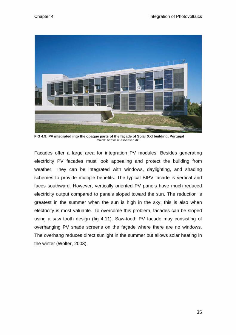
Chapter 4 Integration of Photovoltaics
35
Facades offer a large area for integration PV modules. Besides generating
electricity PV facades must look appealing and protect the building from
weather. They can be integrated with windows, daylighting, and shading
schemes to provide multiple benefits. The typical BIPV facade is vertical and
faces southward. However, vertically oriented PV panels have much reduced
electricity output compared to panels sloped toward the sun. The reduction is
greatest in the summer when the sun is high in the sky; this is also when
electricity is most valuable. To overcome this problem, facades can be sloped
using a saw tooth design (fig 4.11). Saw-tooth PV facade may consisting of
overhanging PV shade screens on the façade where there are no windows.
The overhang reduces direct sunlight in the summer but allows solar heating in
the winter (Wolter, 2003).
FIG 4.9: PV integrated into the opaque parts of the façade of Solar XXI building, Portugal Credit: http://csc.esbensen.dk/
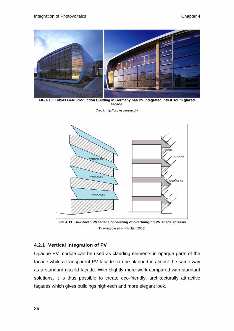
Integration of Photovoltaics Chapter 4
36
4.2.1 Vertical integration of PV
Opaque PV module can be used as cladding elements in opaque parts of the
facade while a transparent PV facade can be planned in almost the same way
as a standard glazed façade. With slightly more work compared with standard
solutions, it is thus possible to create eco-friendly, architecturally attractive
façades which gives buildings high-tech and more elegant look.
FIG 4.10: Tobias Grau Production Building in Germany has PV integrated into it south glazed facade
Credit: http://csc.esbensen.dk/
FIG 4.11: Saw-tooth PV facade consisting of overhanging PV shade screens Drawing based on (Wolter, 2003)
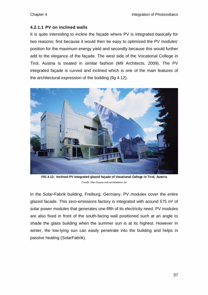
Chapter 4 Integration of Photovoltaics
37
4.2.1.1 PV on inclined walls It is quite interesting to incline the façade where PV is integrated basically for
two reasons; first because it would then be easy to optimized the PV modules’
position for the maximum energy yield and secondly because this would further
add to the elegance of the façade. The west side of the Vocational College in
Tirol, Austria is treated in similar fashion (M9 Architects, 2009). The PV
integrated façade is curved and inclined which is one of the main features of
the architectural expression of the building (fig 4.12).
In the Solar-Fabrik building, Freiburg, Germany, PV modules cover the entire
glazed facade. This zero-emissions factory is integrated with around 575 m² of
solar power modules that generates one-fifth of its electricity need. PV modules
are also fixed in front of the south-facing wall positioned such at an angle to
shade the glass building when the summer sun is at its highest. However In
winter, the low-lying sun can easily penetrate into the building and helps in
passive heating (SolarFabrik).
FIG 4.12: Inclined PV integrated glazed façade of Vocational College in Tirol, Austria
Credit: http://www.m9-architekten.at/

Integration of Photovoltaics Chapter 4
38
Similarly, in Daxford Solar Office the 15metre tall PV façade is designed to
slope back at an angle of 60° mainly for two reasons. First is to maximize the
solar radiation exposure whilst the second is to ensure that there is no
disturbing glare reflected from the wall. Since daylight enters from the south
side between the PV bands, on normal days no artificial lighting is need
(Phillips, 2000).
4.2.1.2 PVs as sunshades In energy efficient buildings, south facing glazings act as energy absorbers and
hence the building can be designed to enable all the solar heat energy to be
distributed from the south facade. However, problems can arise in the summer
when the building overheats and becomes uncomfortable. High solar heat gain
will increase the demand for air conditioning which will in turn increase the
building’s energy requirement. To avoid the energy need for air conditioning,
external sunshades could be a good option to prevent the heat from
FIG 4.14: PV integrated inclined wall of Daxford Solar Office Credit: superstock.com/
FIG 4.13: Inclined PV integrated façade of Solar-Fabrik building, Freiburg, Germany
Credit: http://www.solar-fabrik.de/
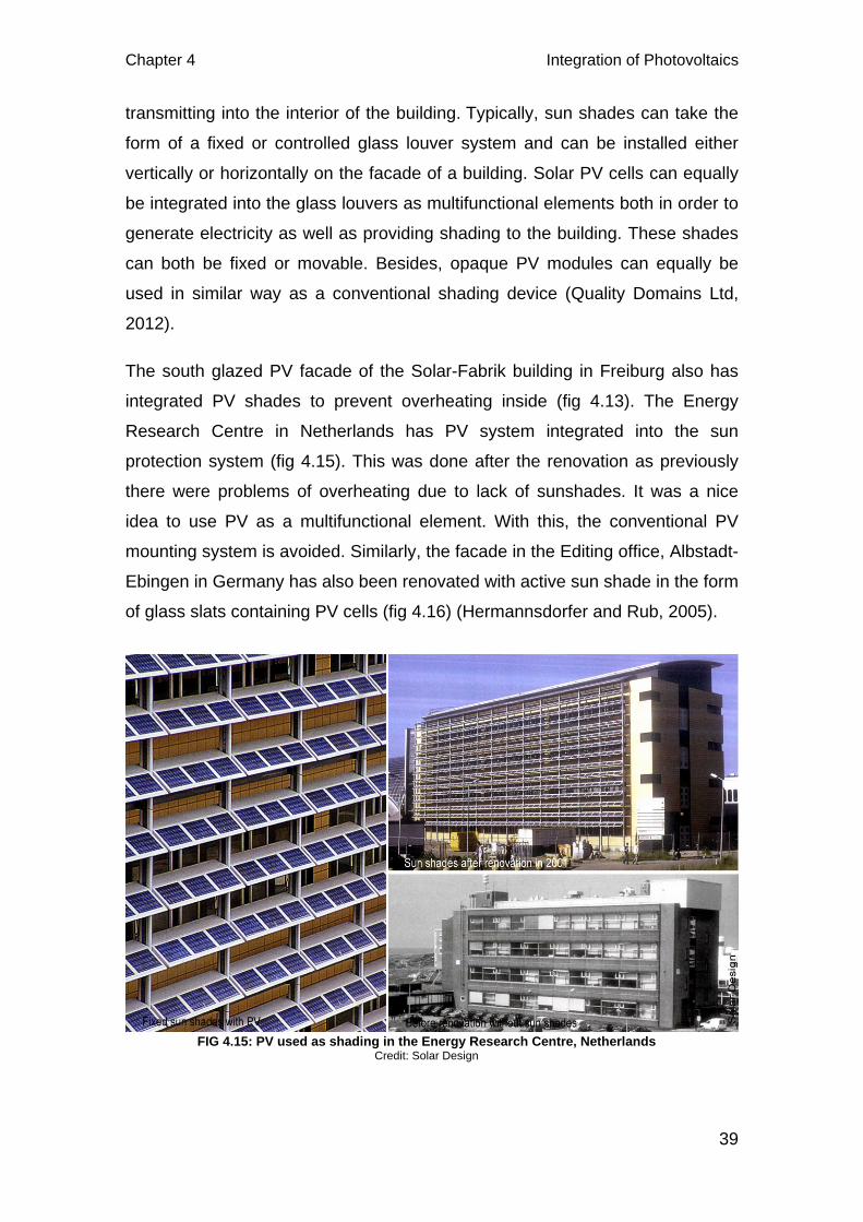
Chapter 4 Integration of Photovoltaics
39
transmitting into the interior of the building. Typically, sun shades can take the
form of a fixed or controlled glass louver system and can be installed either
vertically or horizontally on the facade of a building. Solar PV cells can equally
be integrated into the glass louvers as multifunctional elements both in order to
generate electricity as well as providing shading to the building. These shades
can both be fixed or movable. Besides, opaque PV modules can equally be
used in similar way as a conventional shading device (Quality Domains Ltd,
2012).
The south glazed PV facade of the Solar-Fabrik building in Freiburg also has
integrated PV shades to prevent overheating inside (fig 4.13). The Energy
Research Centre in Netherlands has PV system integrated into the sun
protection system (fig 4.15). This was done after the renovation as previously
there were problems of overheating due to lack of sunshades. It was a nice
idea to use PV as a multifunctional element. With this, the conventional PV
mounting system is avoided. Similarly, the facade in the Editing office, Albstadt-
Ebingen in Germany has also been renovated with active sun shade in the form
of glass slats containing PV cells (fig 4.16) (Hermannsdorfer and Rub, 2005).
FIG 4.15: PV used as shading in the Energy Research Centre, Netherlands Credit: Solar Design
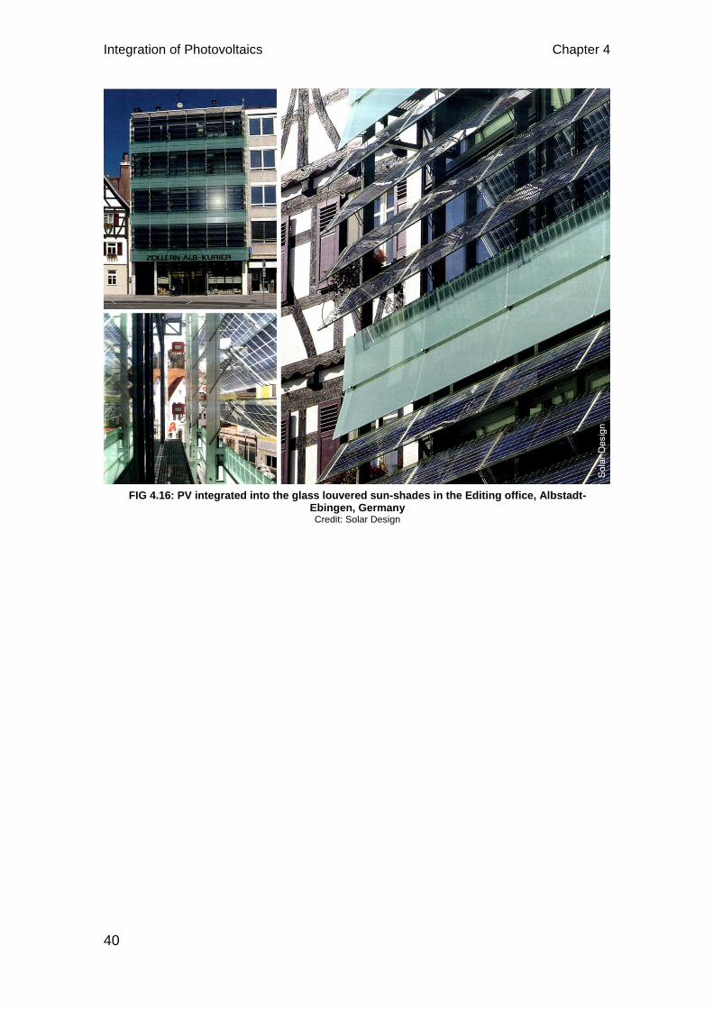
Integration of Photovoltaics Chapter 4
40
FIG 4.16: PV integrated into the glass louvered sun-shades in the Editing office, Albstadt-Ebingen, Germany Credit: Solar Design
Chapter 5 Integration of Solar thermal collectors
41
5 INTEGRATION OF SOLAR THERMAL COLLECTOR
Integration of solar thermal collector systems in buildings can equally add on to
the aesthetics similar to that posed by the photovoltaic systems. The need to
produce and store thermal energy as close as possible near the consumption
site, i.e., in the building itself; makes the integration of this system even more
relevant. Since the existing solar collectors were normally manufactured as
pure technical elements, they have posed a challenge for architectural
integration(Probst and Roecker, 2011). Most solar thermal integrations seen
are of course with the use of specially manufactured modules.
With the popularity of use STC systems for hot water and even space heating,
their integration into the buildings become even more relevant. Integrating
these systems into building means that they should not only answer to the
technical constraints of their specific solar thermal technology, but also become
architectural elements, conceived to be integrated into the building skin, similar
as PV integration. There must exist some level of flexibility in all the system
characteristics affecting the building appearance. These include collector
material and surface texture, absorber colour, shape and size of the modules
and type of jointing. The other equally important aspect of integration is that
they should become multifunctional construction elements, facade cladding
being the most relevant added function for glazed and unglazed flat plate
collectors. With this the need for conventional cladding materials are replaced
and cost can be economized. The use of dummy elements also becomes
relevant on the non-exposed surface of the façade or roof according to the
design (Munari Probst et al., 2007). Overall, the integration must result in public
acceptance, thermal performance, aesthetics and cost effectiveness
(Archibald).
5.1 Roof Integration of STC systems
Besides producing energy for heating water and warming up the spaces inside
the house, the objective of roof integration of STC systems is also to enhance
the overall architectural expression of the building without actually affecting the
normal function of the roof. A roof keeps precipitation out of the building, resist
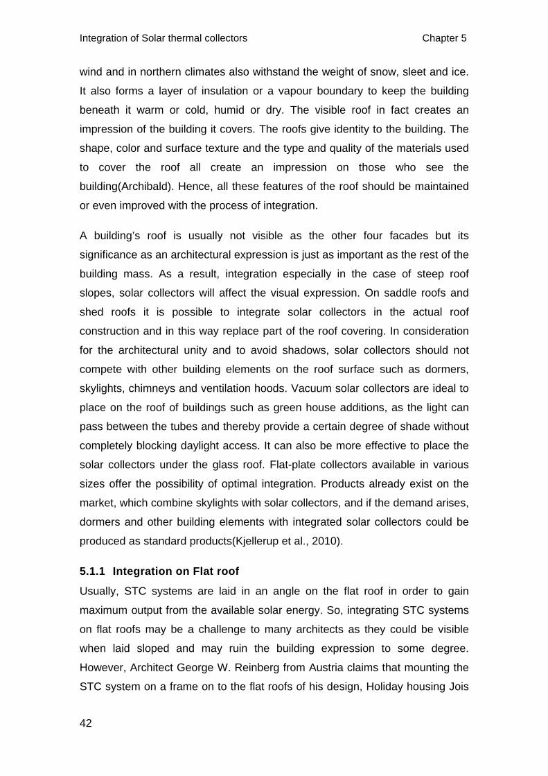
Integration of Solar thermal collectors Chapter 5
42
wind and in northern climates also withstand the weight of snow, sleet and ice.
It also forms a layer of insulation or a vapour boundary to keep the building
beneath it warm or cold, humid or dry. The visible roof in fact creates an
impression of the building it covers. The roofs give identity to the building. The
shape, color and surface texture and the type and quality of the materials used
to cover the roof all create an impression on those who see the
building(Archibald). Hence, all these features of the roof should be maintained
or even improved with the process of integration.
A building’s roof is usually not visible as the other four facades but its
significance as an architectural expression is just as important as the rest of the
building mass. As a result, integration especially in the case of steep roof
slopes, solar collectors will affect the visual expression. On saddle roofs and
shed roofs it is possible to integrate solar collectors in the actual roof
construction and in this way replace part of the roof covering. In consideration
for the architectural unity and to avoid shadows, solar collectors should not
compete with other building elements on the roof surface such as dormers,
skylights, chimneys and ventilation hoods. Vacuum solar collectors are ideal to
place on the roof of buildings such as green house additions, as the light can
pass between the tubes and thereby provide a certain degree of shade without
completely blocking daylight access. It can also be more effective to place the
solar collectors under the glass roof. Flat-plate collectors available in various
sizes offer the possibility of optimal integration. Products already exist on the
market, which combine skylights with solar collectors, and if the demand arises,
dormers and other building elements with integrated solar collectors could be
produced as standard products(Kjellerup et al., 2010).
5.1.1 Integration on Flat roof
Usually, STC systems are laid in an angle on the flat roof in order to gain
maximum output from the available solar energy. So, integrating STC systems
on flat roofs may be a challenge to many architects as they could be visible
when laid sloped and may ruin the building expression to some degree.
However, Architect George W. Reinberg from Austria claims that mounting the
STC system on a frame on to the flat roofs of his design, Holiday housing Jois
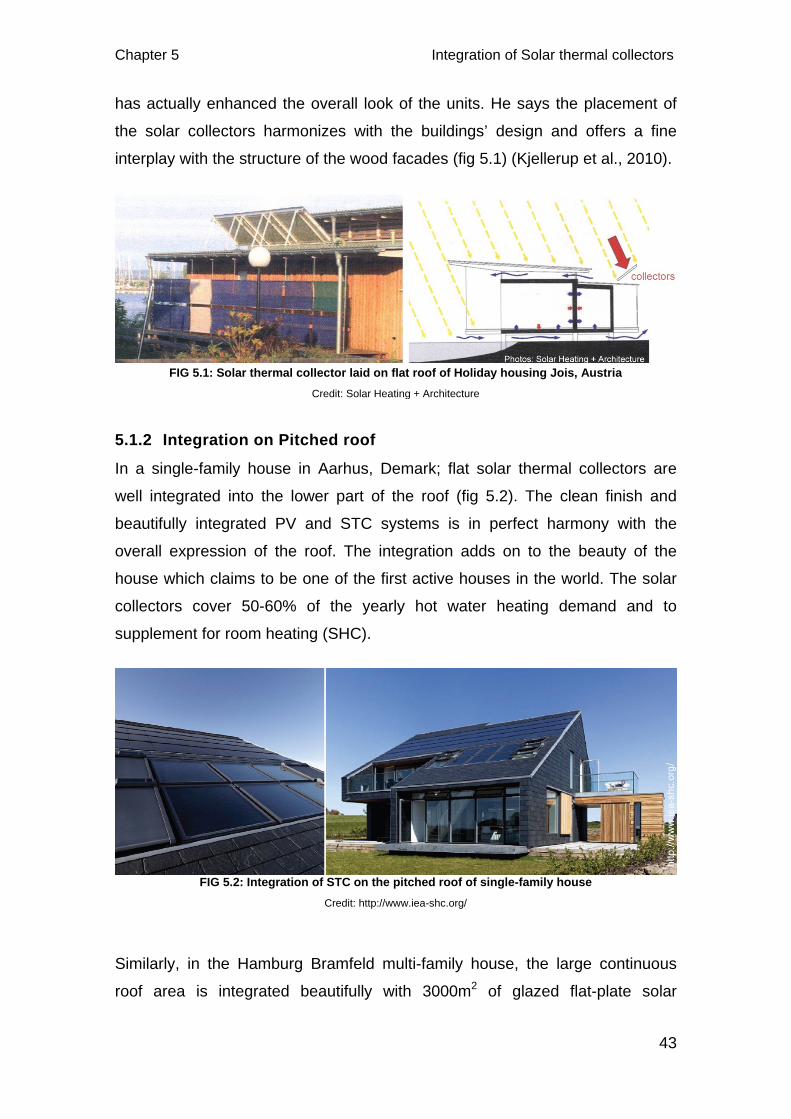
Chapter 5 Integration of Solar thermal collectors
43
has actually enhanced the overall look of the units. He says the placement of
the solar collectors harmonizes with the buildings’ design and offers a fine
interplay with the structure of the wood facades (fig 5.1) (Kjellerup et al., 2010).
5.1.2 Integration on Pitched roof
In a single-family house in Aarhus, Demark; flat solar thermal collectors are
well integrated into the lower part of the roof (fig 5.2). The clean finish and
beautifully integrated PV and STC systems is in perfect harmony with the
overall expression of the roof. The integration adds on to the beauty of the
house which claims to be one of the first active houses in the world. The solar
collectors cover 50-60% of the yearly hot water heating demand and to
supplement for room heating (SHC).
Similarly, in the Hamburg Bramfeld multi-family house, the large continuous
roof area is integrated beautifully with 3000m2 of glazed flat-plate solar
FIG 5.1: Solar thermal collector laid on flat roof of Holiday housing Jois, Austria Credit: Solar Heating + Architecture
FIG 5.2: Integration of STC on the pitched roof of single-family house Credit: http://www.iea-shc.org/
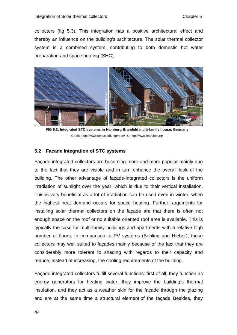
Integration of Solar thermal collectors Chapter 5
44
collectors (fig 5.3). This integration has a positive architectural effect and
thereby an influence on the building’s architecture. The solar thermal collector
system is a combined system, contributing to both domestic hot water
preparation and space heating (SHC).
5.2 Facade Integration of STC systems
Façade integrated collectors are becoming more and more popular mainly due
to the fact that they are visible and in turn enhance the overall look of the
building. The other advantage of façade-integrated collectors is the uniform
irradiation of sunlight over the year, which is due to their vertical installation.
This is very beneficial as a lot of irradiation can be used even in winter, when
the highest heat demand occurs for space heating. Further, arguments for
installing solar thermal collectors on the façade are that there is often not
enough space on the roof or no suitable oriented roof area is available. This is
typically the case for multi-family buildings and apartments with a relative high
number of floors. In comparison to PV systems (Behling and Hieber), these
collectors may well suited to façades mainly because of the fact that they are
considerably more tolerant to shading with regards to their capacity and
reduce, instead of increasing, the cooling requirements of the building.
Façade-integrated collectors fulfill several functions: first of all, they function as
energy generators for heating water, they improve the building’s thermal
insulation, and they act as a weather skin for the façade through the glazing
and are at the same time a structural element of the façade. Besides, they
FIG 5.3: Integrated STC systems in Hamburg Bramfeld multi-family house, Germany Credit: http://www.oekosiedlungen.de/ & http://www.iea-shc.org/
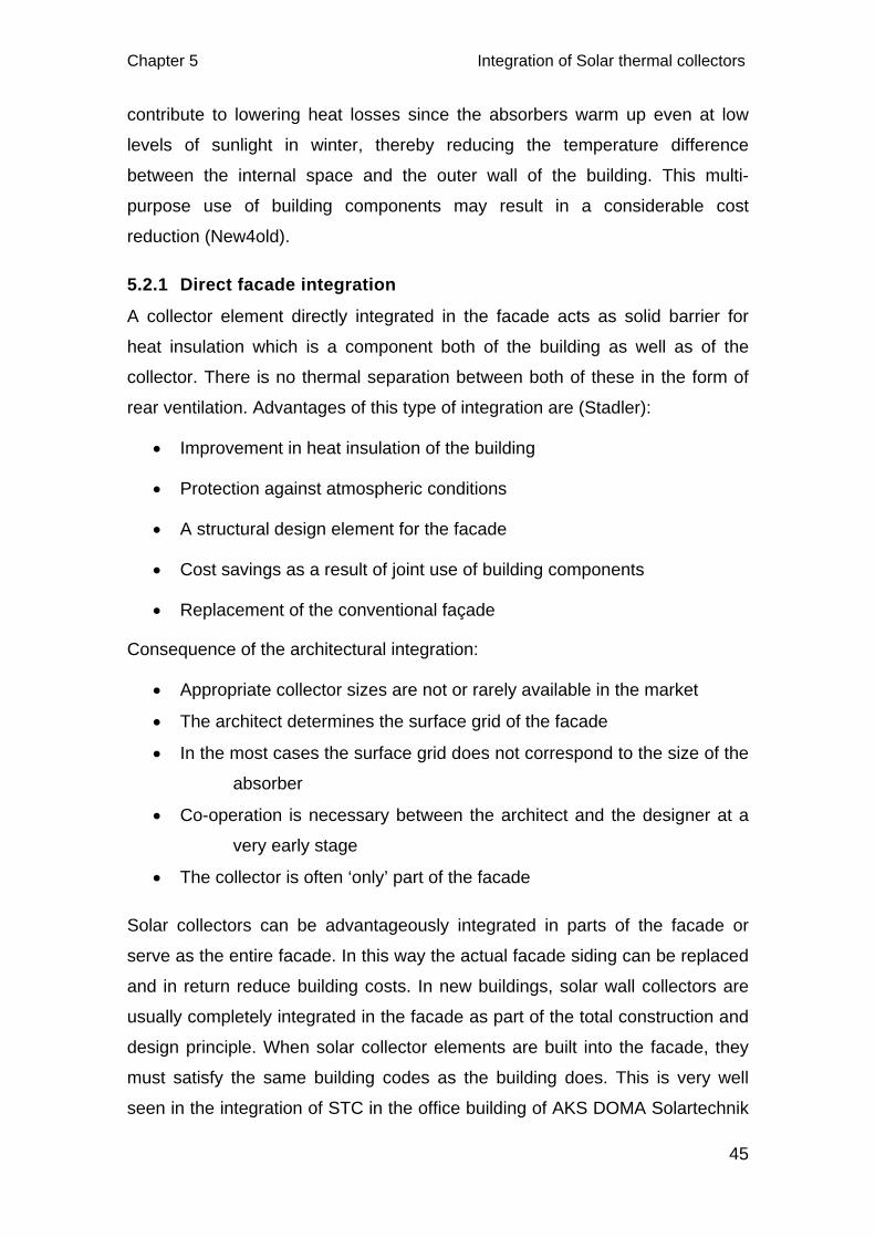
Chapter 5 Integration of Solar thermal collectors
45
contribute to lowering heat losses since the absorbers warm up even at low
levels of sunlight in winter, thereby reducing the temperature difference
between the internal space and the outer wall of the building. This multi-
purpose use of building components may result in a considerable cost
reduction (New4old).
5.2.1 Direct facade integration
A collector element directly integrated in the facade acts as solid barrier for
heat insulation which is a component both of the building as well as of the
collector. There is no thermal separation between both of these in the form of
rear ventilation. Advantages of this type of integration are (Stadler):
• Improvement in heat insulation of the building
• Protection against atmospheric conditions
• A structural design element for the facade
• Cost savings as a result of joint use of building components
• Replacement of the conventional façade
Consequence of the architectural integration:
• Appropriate collector sizes are not or rarely available in the market
• The architect determines the surface grid of the facade
• In the most cases the surface grid does not correspond to the size of the
absorber
• Co-operation is necessary between the architect and the designer at a
very early stage
• The collector is often ‘only’ part of the facade
Solar collectors can be advantageously integrated in parts of the facade or
serve as the entire facade. In this way the actual facade siding can be replaced
and in return reduce building costs. In new buildings, solar wall collectors are
usually completely integrated in the facade as part of the total construction and
design principle. When solar collector elements are built into the facade, they
must satisfy the same building codes as the building does. This is very well
seen in the integration of STC in the office building of AKS DOMA Solartechnik

Integration of Solar thermal collectors Chapter 5
46
(fig 5.4). 80 m2 of glazed flat-plate solar collectors, each with 3000mm x 95 mm
in dimension are integrated into the south facade of the building. The colour of
the absorbers matches to that of the cladding adding to the overall aesthetics of
the building (SHC).
Similarly, for another good integration of STC system to mention is the south
facade of the Centre d’ exploitation des Routes Nationales (CeRN) in
Switzerland. The south facing facade integrated with non-glazed Energie
Solaire metal collectors covering 40% of the building’s heating demand and hot
water (Probst, 2009). The vertical position of the collectors provides a good
compromise between solar gains and architectural integration. Although
dummy elements are rare in case of STC integration, they have been used
here in the non-exposed areas with the same black colour and texture. The
collectors produce maximum energy in the winter season which is used to heat
the floor of the building. During summer the system still produces enough
energy for the hot water needs of the building. The collectors act as
multifunctional elements as it is an excellent corrosion-resistant building
element. They also withstand the impact of aggressive climates without
sustaining any damage and they are fully recyclable (Hullmann et al.).
FIG 5.4: Integrated STC systems on the façade of office building of AKS DOMA Solartedhnik Credit: http://www.iea-shc.org/
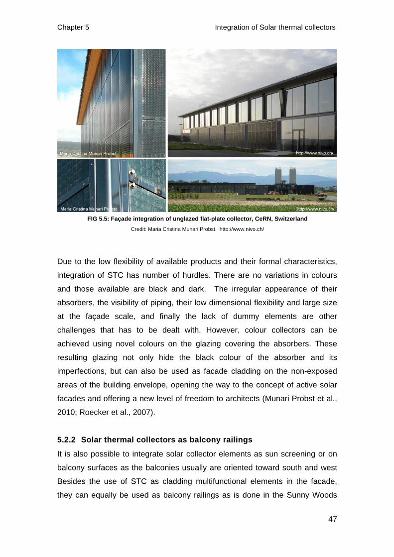
Chapter 5 Integration of Solar thermal collectors
47
Due to the low flexibility of available products and their formal characteristics,
integration of STC has number of hurdles. There are no variations in colours
and those available are black and dark. The irregular appearance of their
absorbers, the visibility of piping, their low dimensional flexibility and large size
at the façade scale, and finally the lack of dummy elements are other
challenges that has to be dealt with. However, colour collectors can be
achieved using novel colours on the glazing covering the absorbers. These
resulting glazing not only hide the black colour of the absorber and its
imperfections, but can also be used as facade cladding on the non-exposed
areas of the building envelope, opening the way to the concept of active solar
facades and offering a new level of freedom to architects (Munari Probst et al.,
2010; Roecker et al., 2007).
5.2.2 Solar thermal collectors as balcony railings
It is also possible to integrate solar collector elements as sun screening or on
balcony surfaces as the balconies usually are oriented toward south and west
Besides the use of STC as cladding multifunctional elements in the facade,
they can equally be used as balcony railings as is done in the Sunny Woods
FIG 5.5: Façade integration of unglazed flat-plate collector, CeRN, Switzerland Credit: Maria Cristina Munari Probst, http://www.nivo.ch/
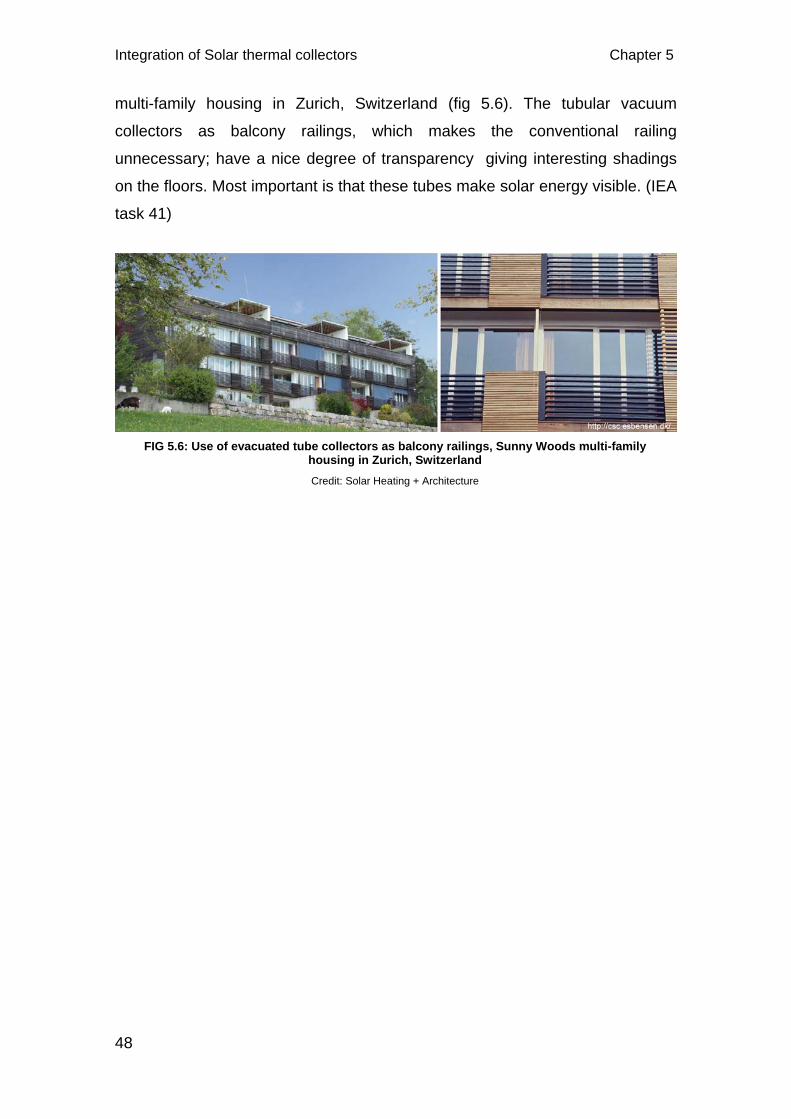
Integration of Solar thermal collectors Chapter 5
48
multi-family housing in Zurich, Switzerland (fig 5.6). The tubular vacuum
collectors as balcony railings, which makes the conventional railing
unnecessary; have a nice degree of transparency giving interesting shadings
on the floors. Most important is that these tubes make solar energy visible. (IEA
task 41)
FIG 5.6: Use of evacuated tube collectors as balcony railings, Sunny Woods multi-family housing in Zurich, Switzerland Credit: Solar Heating + Architecture
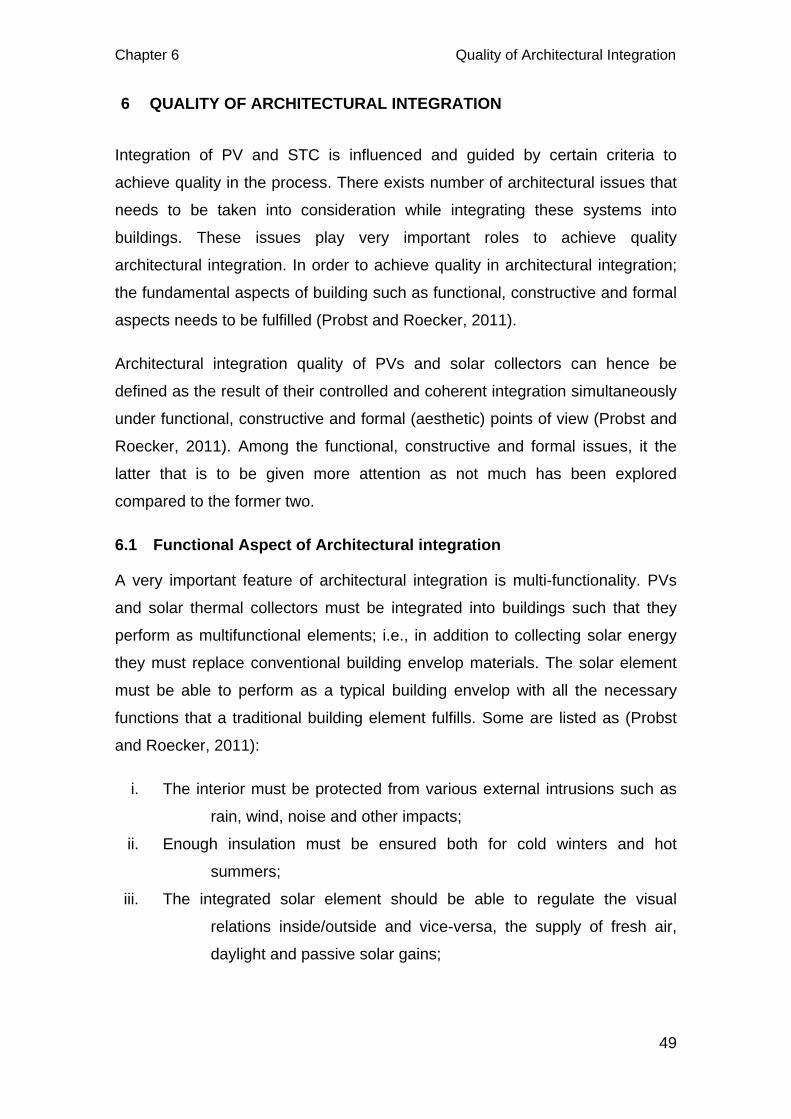
Chapter 6 Quality of Architectural Integration
49
6 QUALITY OF ARCHITECTURAL INTEGRATION
Integration of PV and STC is influenced and guided by certain criteria to
achieve quality in the process. There exists number of architectural issues that
needs to be taken into consideration while integrating these systems into
buildings. These issues play very important roles to achieve quality
architectural integration. In order to achieve quality in architectural integration;
the fundamental aspects of building such as functional, constructive and formal
aspects needs to be fulfilled (Probst and Roecker, 2011).
Architectural integration quality of PVs and solar collectors can hence be
defined as the result of their controlled and coherent integration simultaneously
under functional, constructive and formal (aesthetic) points of view (Probst and
Roecker, 2011). Among the functional, constructive and formal issues, it the
latter that is to be given more attention as not much has been explored
compared to the former two.
6.1 Functional Aspect of Architectural integration
A very important feature of architectural integration is multi-functionality. PVs
and solar thermal collectors must be integrated into buildings such that they
perform as multifunctional elements; i.e., in addition to collecting solar energy
they must replace conventional building envelop materials. The solar element
must be able to perform as a typical building envelop with all the necessary
functions that a traditional building element fulfills. Some are listed as (Probst
and Roecker, 2011):
i. The interior must be protected from various external intrusions such as
rain, wind, noise and other impacts;
ii. Enough insulation must be ensured both for cold winters and hot
summers;
iii. The integrated solar element should be able to regulate the visual
relations inside/outside and vice-versa, the supply of fresh air,
daylight and passive solar gains;

Quality of Architectural Integration Chapter 6
50
iv. They should be able to maintain user’s comfort even when a reduction of
the use of non-renewable energy for heating, cooling and lighting
is made;
The opaque parts of the envelop in a building like walls and roofs, protect the
interior from intrusions, rain, wind, noise, heat, cold and other impacts (Huan,
2011; Probst and Roecker, 2011). These opaque parts are structural/non-
structural multilayer systems which may also include insulation. Insulation are
usually used in buildings’ outer layer in very cold or very hot places to minimise
loss or gain in temperature in the interior of the building. The transparent or
translucent parts like windows, atrium, glass cladding allow daylight, natural
ventilation and passive solar gains into the building. They also visually link the
interior with the exterior in addition to ensuring the whole set of protection
functions similar to that of the opaque parts. These transparent parts may also
be composed of mobile components and systems such as shading devices for
regulating views, day lighting, passive solar gains and even natural
ventilation(Probst and Roecker, 2011).
As per Probst and Roecker (2011), Integrating PVs and collectors into the
building envelop requires to understand where opaque parts, transparent parts
and fixed mobile elements are located and their compatibility in terms of
material and function. For eg: standard opaque PV modules and thermal
collectors are most likely to be integrated into the roof or even on the opaque
parts of facades while thin film PVs on the atrium or windows. Normally, solar
thermal collectors have less compatibility with the transparent parts of the
building mainly due to the fact that their absorbers are opaque. In case of PV
systems, they can be well integrated into these transparent parts with the
possibility to laminate PVs in glass modules (fig 6.1, left).
Probst (2009) has said that the multilayer composition of flat plate collectors is
suitable for the integration in the multilayer composition of the opaque envelop
parts like walls and roofs. The insulation behind the absorber plate and the
insulation of the building envelop can potentially become one single element or
complement each other; the absorber for unglazed collectors and the glazing
for glazed ones can take, under a purely functional point of view, replacing the
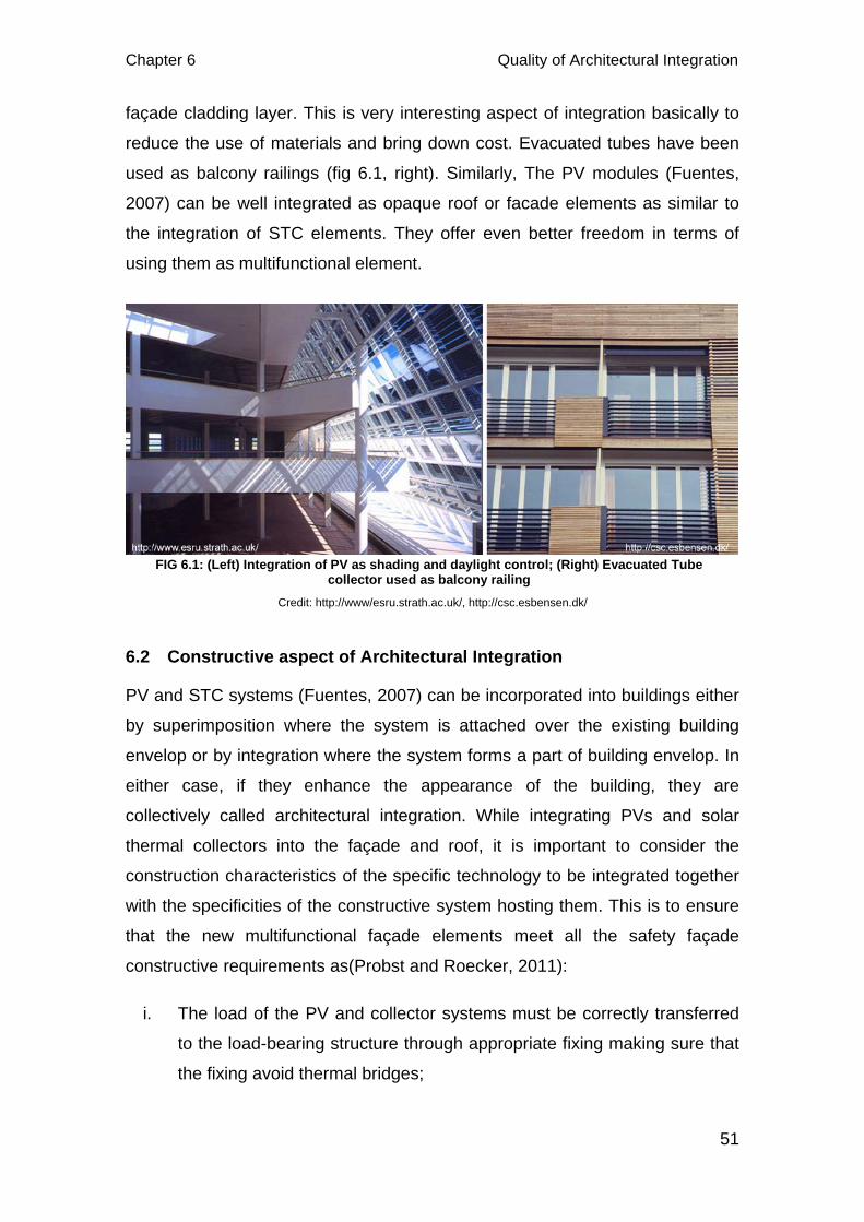
Chapter 6 Quality of Architectural Integration
51
façade cladding layer. This is very interesting aspect of integration basically to
reduce the use of materials and bring down cost. Evacuated tubes have been
used as balcony railings (fig 6.1, right). Similarly, The PV modules (Fuentes,
2007) can be well integrated as opaque roof or facade elements as similar to
the integration of STC elements. They offer even better freedom in terms of
using them as multifunctional element.
6.2 Constructive aspect of Architectural Integration
PV and STC systems (Fuentes, 2007) can be incorporated into buildings either
by superimposition where the system is attached over the existing building
envelop or by integration where the system forms a part of building envelop. In
either case, if they enhance the appearance of the building, they are
collectively called architectural integration. While integrating PVs and solar
thermal collectors into the façade and roof, it is important to consider the
construction characteristics of the specific technology to be integrated together
with the specificities of the constructive system hosting them. This is to ensure
that the new multifunctional façade elements meet all the safety façade
constructive requirements as(Probst and Roecker, 2011):
i. The load of the PV and collector systems must be correctly transferred
to the load-bearing structure through appropriate fixing making sure that
the fixing avoid thermal bridges;
FIG 6.1: (Left) Integration of PV as shading and daylight control; (Right) Evacuated Tube collector used as balcony railing
Credit: http://www/esru.strath.ac.uk/, http://csc.esbensen.dk/
Quality of Architectural Integration Chapter 6
52
ii. These solar technologies must be able to withstand fire and harshness
of the weather;
iii. They should resist wind load and other impacts and should be safe in
case of damages;
iv. The resulting problems due to the temperature rise behind the systems
must be rectified;
v. Fixing details and jointing should make the PV and collector system’s
material expansions compatible with those of the other envelop
materials.
vi. Vapour transfer through the wall should avoid condensation layers, and
allow the wall to dry correctly.
Point vi) is very important to consider while integrating flat plate collectors or
cladding PV systems without an air gap. In normal cases, vapour transfer takes
place from the higher temperature (inside) to the lower temperature (outside).
So, the vapour barriers are placed on the inner warm part of the wall to avoid
condensation layers. In doing so, special attention must be taken to protect
insulation materials and wood if they are used. Mounting solar collectors
directly to the wall without an air gap causes a fundamental modification of the
vapour transfer; i.e., it flows out when the cladded PV or STC systems are cold
and it is the other way round when they are heated up(Probst and Roecker,
2011). These facts must be carefully considered during integration.
To explain the construction aspect on integration, temperature of solar module
could be one factor. The output in case of PVs start degrading as the module
temperature start rising. In BP solar building at NTNU, Trondheim, 80cm cavity
created between the glass façade and the adjacent building’s wall assists in
venting the cells thereby increasing efficiency (fig 6.2) (Aschehoug et al., 2003).
Similarly, In Albstadt-Ebingen editing office in Germany, the solar slats used
also as shading are hung 50 cm in front of the existing facade (fig 4.16)
(Hermannsdorfer and Rub, 2005).
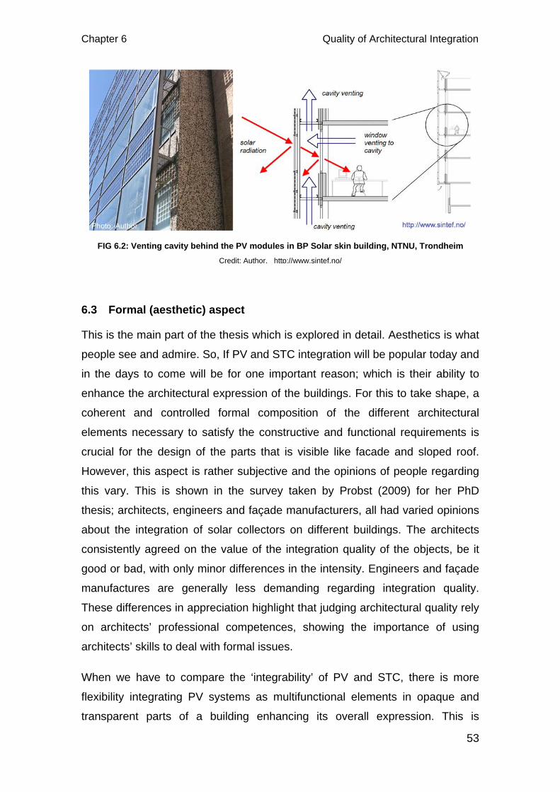
Chapter 6 Quality of Architectural Integration
53
6.3 Formal (aesthetic) aspect
This is the main part of the thesis which is explored in detail. Aesthetics is what
people see and admire. So, If PV and STC integration will be popular today and
in the days to come will be for one important reason; which is their ability to
enhance the architectural expression of the buildings. For this to take shape, a
coherent and controlled formal composition of the different architectural
elements necessary to satisfy the constructive and functional requirements is
crucial for the design of the parts that is visible like facade and sloped roof.
However, this aspect is rather subjective and the opinions of people regarding
this vary. This is shown in the survey taken by Probst (2009) for her PhD
thesis; architects, engineers and façade manufacturers, all had varied opinions
about the integration of solar collectors on different buildings. The architects
consistently agreed on the value of the integration quality of the objects, be it
good or bad, with only minor differences in the intensity. Engineers and façade
manufactures are generally less demanding regarding integration quality.
These differences in appreciation highlight that judging architectural quality rely
on architects’ professional competences, showing the importance of using
architects’ skills to deal with formal issues.
When we have to compare the ‘integrability’ of PV and STC, there is more
flexibility integrating PV systems as multifunctional elements in opaque and
transparent parts of a building enhancing its overall expression. This is
FIG 6.2: Venting cavity behind the PV modules in BP Solar skin building, NTNU, Trondheim Credit: Author, http://www.sintef.no/
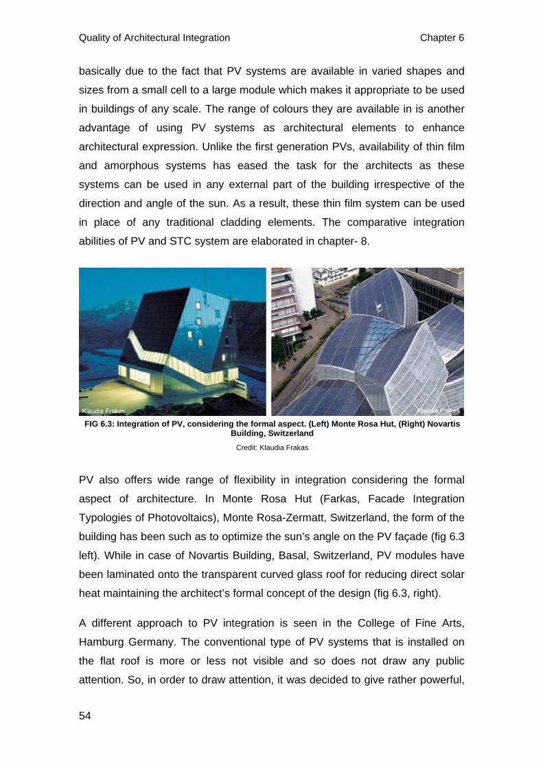
Quality of Architectural Integration Chapter 6
54
basically due to the fact that PV systems are available in varied shapes and
sizes from a small cell to a large module which makes it appropriate to be used
in buildings of any scale. The range of colours they are available in is another
advantage of using PV systems as architectural elements to enhance
architectural expression. Unlike the first generation PVs, availability of thin film
and amorphous systems has eased the task for the architects as these
systems can be used in any external part of the building irrespective of the
direction and angle of the sun. As a result, these thin film system can be used
in place of any traditional cladding elements. The comparative integration
abilities of PV and STC system are elaborated in chapter- 8.
PV also offers wide range of flexibility in integration considering the formal
aspect of architecture. In Monte Rosa Hut (Farkas, Facade Integration
Typologies of Photovoltaics), Monte Rosa-Zermatt, Switzerland, the form of the
building has been such as to optimize the sun’s angle on the PV façade (fig 6.3
left). While in case of Novartis Building, Basal, Switzerland, PV modules have
been laminated onto the transparent curved glass roof for reducing direct solar
heat maintaining the architect’s formal concept of the design (fig 6.3, right).
A different approach to PV integration is seen in the College of Fine Arts,
Hamburg Germany. The conventional type of PV systems that is installed on
the flat roof is more or less not visible and so does not draw any public
attention. So, in order to draw attention, it was decided to give rather powerful,
FIG 6.3: Integration of PV, considering the formal aspect. (Left) Monte Rosa Hut, (Right) Novartis Building, Switzerland
Credit: Klaudia Frakas
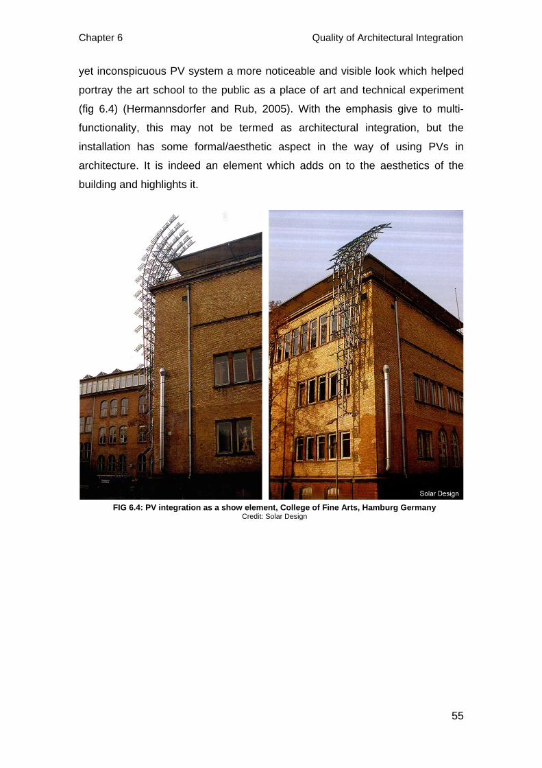
Chapter 6 Quality of Architectural Integration
55
yet inconspicuous PV system a more noticeable and visible look which helped
portray the art school to the public as a place of art and technical experiment
(fig 6.4) (Hermannsdorfer and Rub, 2005). With the emphasis give to multi-
functionality, this may not be termed as architectural integration, but the
installation has some formal/aesthetic aspect in the way of using PVs in
architecture. It is indeed an element which adds on to the aesthetics of the
building and highlights it.
FIG 6.4: PV integration as a show element, College of Fine Arts, Hamburg Germany Credit: Solar Design
Architectural Integration Requirements Chapter 7
56
7 ARCHITECTURAL INTEGRATION REQUIREMENTS
To achieve quality in the architectural integration of PV and STC systems
certain requirements need to be fulfilled. The global integration quality depends
not just on module shape, size and colour but also on all formal characteristics
as (Probst and Roecker, 2011):
i. Field size and position of PV or collector systems
ii. Materials and surface texture
iii. Colour of the cells for PV systems and absorbers for solar collectors
iv. Shape and size of the modules
v. Type of jointing
vi. Multifunctional elements
For successful integration, above mentioned characteristics must all be
coherent with the overall building design logic. The characteristics with the
relevant examples of the use of PV and Collectors are described below.
7.1 Field Size and Position
It is very important that the size and position of the PV and collector systems be
coherent with the overall architectural composition of the whole building and not
just with in the façade or part of the building where they are being installed (fig
7.1 & 7.2). However, it may always not be easy to achieve this and in order to
achieve; certain parameters have to be followed. The parameters that influence
the location, shape and size of the PV and collector systems are (Probst, 2009;
Probst and Roecker, 2011):
- Position and dimension of the available exposed surface of the roof or
façade
- Orientation of the surface available
- Energy requirements desired
- Solar technology
- Architectural needs of the building
Chapter 7 Architectural Integration Requirements
57
The surface or part of the building that is available for integration directly
influences the energy production of the solar systems. In case of new
construction, available exposed surface can be created according to the energy
requirement aimed for. However, for retrofit projects the energy production has
to be adjusted according to the available exposed surfaces. In addition, the
choice of solar technology also influences production and exposed surface
requirements. In case of PV systems, crystalline cells produce much more
electricity than amorphous solar cells. So, for the yield of same amount of
power, amorphous solar cells have to be installed on a larger surface than for
crystalline cells. Same applies for solar collectors. Evacuated tube collectors
are more efficient than flat plate collectors. So, the choice of a specific solar
thermal technology affects the exposed surface requirements.
An effective approach to the positioning and dimensioning issue is to use the
PV and thermal collectors as multifunctional elements serving both as energy
generators and roof/façade elements. With this, the architect has to design in
such a way that he uses fewer elements as possible as each fulfils several
functions. Use of PV or solar collectors all over the surface may often be
unnecessary and difficult due to practicalities. So, the use of dummy elements
will help to decouple the geometric dimensioning of the system and bring
uniformity in the appearance of the system. However, the down side of this is
that in most occasions, such applications require the development of a tailored
product specific to just one project, and are therefore very expensive (Probst,
2009; Probst and Roecker, 2011).

Architectural Integration Requirements Chapter 7
58
FIG 7.2: Architectural integration of STC systems on the inclined façade of multifamily dwelling, Gleisdorf, Germany. The formal characteristics of the STC system have an impact on the
integration quality. Credit: Maria Cristina Munari Probst
FIG 7.1: Architectural integration of PV on the roof of a Church, Carlow, Germany. The formal characteristics of the PV system have an impact on the integration quality.
Credit: Solar Design
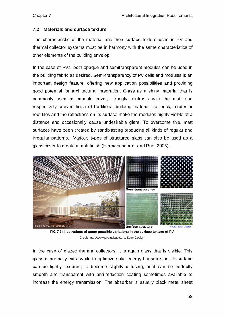
Chapter 7 Architectural Integration Requirements
59
7.2 Materials and surface texture
The characteristic of the material and their surface texture used in PV and
thermal collector systems must be in harmony with the same characteristics of
other elements of the building envelop.
In the case of PVs, both opaque and semitransparent modules can be used in
the building fabric as desired. Semi-transparency of PV cells and modules is an
important design feature, offering new application possibilities and providing
good potential for architectural integration. Glass as a shiny material that is
commonly used as module cover, strongly contrasts with the matt and
respectively uneven finish of traditional building material like brick, render or
roof tiles and the reflections on its surface make the modules highly visible at a
distance and occasionally cause undesirable glare. To overcome this, matt
surfaces have been created by sandblasting producing all kinds of regular and
irregular patterns. Various types of structured glass can also be used as a
glass cover to create a matt finish (Hermannsdorfer and Rub, 2005).
In the case of glazed thermal collectors, it is again glass that is visible. This
glass is normally extra white to optimize solar energy transmission. Its surface
can be lightly textured, to become slightly diffusing, or it can be perfectly
smooth and transparent with anti-reflection coating sometimes available to
increase the energy transmission. The absorber is usually black metal sheet
FIG 7.3: Illustrations of some possible variations in the surface texture of PV Credit: http://www.pvdatabase.org, Solar Design
Architectural Integration Requirements Chapter 7
60
mainly made of copper, aluminium or steel and can either be in one piece or
made of a row of metal strips. The geometry and surface texture of absorbers
can be quite diverse depending on the manufacturer, but usually no flexibility is
offered within one specific product. For unglazed collectors, the absorber metal
sheet is the only visible layer. The glass tubes, the absorber metal strip inside
and in most cases also the back module sheets are visible in the case of
evacuated tubes(Probst, 2009; Probst and Roecker, 2011).
7.3 Colour
The colours of the crystalline and amorphous silicon cells are normally blue. By
modifying the anti-reflection layer it is possible to create other colours. Thin film
solar cells consisting of amorphous silicon or CIS are black in colour while
CdTe-cells have a greenish look. The range of colours gives the possibility to
produce any kind of pattern that is desired in a building fabric(Hermannsdorfer
and Rub, 2005).
The absorbers used in solar thermal collectors are usually black or dark blue to
assist their heat collection function. The absorber colour results most of the
time from selective coatings used to optimize absorption and to reduce
emission losses. The colour of these coatings can change according to the
angle of vision, so that a black absorber may look violet or blue or red
depending on the incidence angle of the sun on the surface. Dark brown and
dark green shades have also appeared in the market but very little (Probst and
Roecker, 2011).
Within the chosen technology, the different products available in the market
should be explored to find the colour and surface texture most suitable for the
given application. PV products provide more freedom compared to the
collectors in this regards. However, it would be a clever approach to define the
materials of the other envelope elements so as to be compatible with the
materials, textures and colours of the chosen collectors which is possible in
new construction.

Chapter 7 Architectural Integration Requirements
61
7.4 Shape and size of the modules
The shapes of the module of the PV and collector systems have to be
compatible with the building composition grid and with the various dimensions
of the other façade elements (Probst and Roecker, 2011). It is actually the
choice of the technology that affects the basic form of the module. For PV
systems, mono and polycrystalline modules come in standard sizes and can be
bulky while thin films can have varied shape and sizes. The development of
cut-to-size module prototypes had the aim of providing modules whose size
can be adapted directly on site as in the Surplus-home of team Germany for
the Solar Decathlon 2009 (fig 7.5, top-left). Even though most of the products in
the market come in standard module size, there is maximum freedom in the
use of PVs on roofs and façade elements. There will be variations in the basic
form of collector module shape and size as according to the exposed available
surface and type of collectors chosen.
7.5 Type of Jointing
Jointing types must be carefully considered while choosing the product as
different jointing types differently underline the modular grid of the system in
relation to the building (Probst and Roecker, 2011). In the surplus-home by TU
Darmstadt for the Solar Decathlon 2009, the PV facade cladding was done in
the traditional shingles principle. It is also the jointing that makes the PV
FIG 7.4: (Left) Range of colours in PV; (Right) visible colours due to the sunlight striking onto the extra white glass above the absorber of STC system,
credit: credit: Klaudia Farkas; Maria Cristina Munari Probst
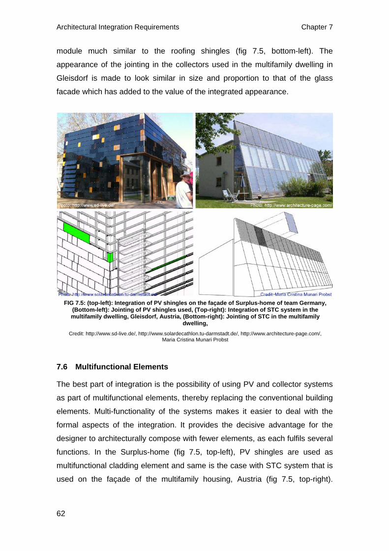
Architectural Integration Requirements Chapter 7
62
module much similar to the roofing shingles (fig 7.5, bottom-left). The
appearance of the jointing in the collectors used in the multifamily dwelling in
Gleisdorf is made to look similar in size and proportion to that of the glass
facade which has added to the value of the integrated appearance.
7.6 Multifunctional Elements
The best part of integration is the possibility of using PV and collector systems
as part of multifunctional elements, thereby replacing the conventional building
elements. Multi-functionality of the systems makes it easier to deal with the
formal aspects of the integration. It provides the decisive advantage for the
designer to architecturally compose with fewer elements, as each fulfils several
functions. In the Surplus-home (fig 7.5, top-left), PV shingles are used as
multifunctional cladding element and same is the case with STC system that is
used on the façade of the multifamily housing, Austria (fig 7.5, top-right).
FIG 7.5: (top-left): Integration of PV shingles on the façade of Surplus-home of team Germany, (Bottom-left): Jointing of PV shingles used, (Top-right): Integration of STC system in the multifamily dwelling, Gleisdorf, Austria, (Bottom-right): Jointing of STC in the multifamily
dwelling, Credit: http://www.sd-live.de/, http://www.solardecathlon.tu-darmstadt.de/, http://www.architecture-page.com/,
Maria Cristina Munari Probst
Chapter 8 PV or STC: Better ability to Architectural Integration?
63
8 PV OR STC: BETTER ABILITY TO ARCHITECTURAL INTEGRATION?
With the increasing awareness over the environment and climate change;
government of different nationals formulating policies in favour of renewable
energy, energy efficiency, on-site renewable energy production to reducing
CO2 emissions; even more and more homes will definitely be powered by solar
energy in the days to come. This gives an overview that, PV and STC systems
which are common and reliable on-site renewable solar energy generators will
abundantly be used in buildings. So, if the integration of these systems into
buildings is done wisely and cleverly, they will not only generate energy but will
also add to the overall architectural expression of the building. Within this
context of fulfilling the integration requirements and rendering quality
integration, there has been a debate as to which systems among the two would
best suit for architectural integration.
PV and STC systems are fundamentally different, as the former is designed to
transform the solar radiation into electricity, while the latter is designed to
transform it into heat. So, these systems are used to produce completely two
different types of energy and hence have very different transportation and
storage issues. This brings different formal and operating constraints, leading
to different building integration possibilities (Probst and Roecker, 2011).
Photovoltaic systems have a number of merits and unique advantages over
conventional power-generating technologies. These systems can be designed
for a variety of applications and operational requirements, and can be used for
either centralised or distributed power generation. PV systems have no moving
parts, are modular, easily expandable and even transportable in some cases.
Energy independence and environmental compatibility are two attractive
features of PV systems. The fuel (sunlight) is free, and no noise or pollution is
created from operating PV systems. At present, the high cost of PV modules
and equipment (as compared to conventional energy sources) is the primary
limiting factor for the technology. Consequently, the economic value of PV
systems is realised over many years. In some cases, the surface area
requirements for PV arrays may be a limiting factor (GreenSpec, 2012;
Hestnes, 2012).
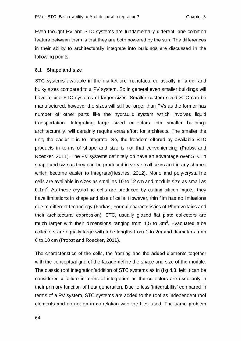
PV or STC: Better ability to Architectural Integration? Chapter 8
64
Even thought PV and STC systems are fundamentally different, one common
feature between them is that they are both powered by the sun. The differences
in their ability to architecturally integrate into buildings are discussed in the
following points.
8.1 Shape and size
STC systems available in the market are manufactured usually in larger and
bulky sizes compared to a PV system. So in general even smaller buildings will
have to use STC systems of larger sizes. Smaller custom sized STC can be
manufactured, however the sizes will still be larger than PVs as the former has
number of other parts like the hydraulic system which involves liquid
transportation. Integrating large sized collectors into smaller buildings
architecturally, will certainly require extra effort for architects. The smaller the
unit, the easier it is to integrate. So, the freedom offered by available STC
products in terms of shape and size is not that conveniencing (Probst and
Roecker, 2011). The PV systems definitely do have an advantage over STC in
shape and size as they can be produced in very small sizes and in any shapes
which become easier to integrate(Hestnes, 2012). Mono and poly-crystalline
cells are available in sizes as small as 10 to 12 cm and module size as small as
0.1m2. As these crystalline cells are produced by cutting silicon ingots, they
have limitations in shape and size of cells. However, thin film has no limitations
due to different technology (Farkas, Formal characteristics of Photovoltaics and
their architectural expression). STC, usually glazed flat plate collectors are
much larger with their dimensions ranging from 1.5 to 3m2. Evacuated tube
collectors are equally large with tube lengths from 1 to 2m and diameters from
6 to 10 cm (Probst and Roecker, 2011).
The characteristics of the cells, the framing and the added elements together
with the conceptual grid of the facade define the shape and size of the module.
The classic roof integration/addition of STC systems as in (fig 4.3, left; ) can be
considered a failure in terms of integration as the collectors are used only in
their primary function of heat generation. Due to less ‘integrability’ compared in
terms of a PV system, STC systems are added to the roof as independent roof
elements and do not go in co-relation with the tiles used. The same problem

Chapter 8 PV or STC: Better ability to Architectural Integration?
65
will not be faced while integrating PV on the roof which can be seen in the
integration of PV roof tiles in a building in Delamont Country Park Ireland (fig
4.5, top; fig 8.1, bottom-left). The black PV tiles perfectly match with the normal
tile used for roofing in both shape and size.
In case of STC systems, The Techtile Therma, produced by company called
REM can be a new and innovative way of integrating into tiled roofs. It is
equipped with a solar collector consisting of a series of 6 glass tubes with dia.
47mm, length 1,500 mm, double cavity borosilicate, welded at the ends,
creating a vacuum inside (fig 8.1, centre & right) With this, the integration looks
clean and each tile appear to be separate unit even though six such tiles
integrate one vacuum tube. However, this method is certainly not that easy in
terms of installation compared to that of a PV system and hence have not
produced examples of their integration. We can find few more examples of this
kind of products but they have not usually been commercially used (REM,
2012).
8.2 Positioning
The positioning of both PV and STC systems is defined by energy and
architectural needs. It is only the suitable locations on the building which is
determined by solar exposure, suitable area, energy production goals, etc that
is equipped with PV and STC systems. In case of specific architectural needs,
the remaining spaces can be covered or clad with dummy elements(Probst and
FIG 8.1: (top-left): PV tiles on the roof, (bottom-left): PV on the roof Delamont Country Park Ireland building, (center & right): Techtile Therma STC systems on the roof
credit: http://solarpowerpanels.ws/,http://www.horizonrenewables.co.uk/, http://www.remenergies.it/
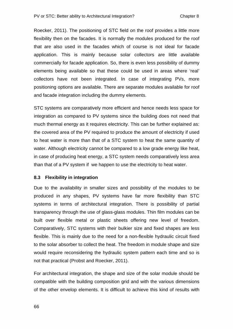
PV or STC: Better ability to Architectural Integration? Chapter 8
66
Roecker, 2011). The positioning of STC field on the roof provides a little more
flexibility then on the facades. It is normally the modules produced for the roof
that are also used in the facades which of course is not ideal for facade
application. This is mainly because solar collectors are little available
commercially for facade application. So, there is even less possibility of dummy
elements being available so that these could be used in areas where ‘real’
collectors have not been integrated. In case of integrating PVs, more
positioning options are available. There are separate modules available for roof
and facade integration including the dummy elements.
STC systems are comparatively more efficient and hence needs less space for
integration as compared to PV systems since the building does not need that
much thermal energy as it requires electricity. This can be further explained as:
the covered area of the PV required to produce the amount of electricity if used
to heat water is more than that of a STC system to heat the same quantity of
water. Although electricity cannot be compared to a low grade energy like heat,
in case of producing heat energy, a STC system needs comparatively less area
than that of a PV system if we happen to use the electricity to heat water.
8.3 Flexibility in integration
Due to the availability in smaller sizes and possibility of the modules to be
produced in any shapes, PV systems have far more flexibility than STC
systems in terms of architectural integration. There is possibility of partial
transparency through the use of glass-glass modules. Thin film modules can be
built over flexible metal or plastic sheets offering new level of freedom.
Comparatively, STC systems with their bulkier size and fixed shapes are less
flexible. This is mainly due to the need for a non-flexible hydraulic circuit fixed
to the solar absorber to collect the heat. The freedom in module shape and size
would require reconsidering the hydraulic system pattern each time and so is
not that practical (Probst and Roecker, 2011).
For architectural integration, the shape and size of the solar module should be
compatible with the building composition grid and with the various dimensions
of the other envelop elements. It is difficult to achieve this kind of results with

Chapter 8 PV or STC: Better ability to Architectural Integration?
67
the integration of STC systems while with the PV system it is fairly easy mainly
because of their flexibility. This difference in flexibilities imply very different
constraints when choosing the shape and placement of these solar elements
especially for façade integration (Probst and Roecker, 2011).
8.4 Range of Colours
The PV cells have a larger variation in the range of colours as compared to that
of the absorbers of the solar thermal collectors. This is very advantageous in
terms of architectural integration especially in the visible parts of the building
where colours play a very important role in aesthetics and architectural concept
and expression.
Coloured PV cells open up a new field of design possibilities in architecture.
These coloured cells offer a wide range of new design applications adding
aesthetic value to the building especially in the facade. PV modules are
available in a wide range of colours. Crystalline modules are crystal-blue to
black in order to maximise sunlight absorption. Other colours can be achieved
by modifying the thickness of the anti-reflection coating on the surface of the
solar cell. Lighter the shade, the less efficient the solar cell. Thin-film modules
are reddish-brown or black (Solar fassade, 2011).
The blue coloured mono and poly-crystalline are the most efficient of the PVs.
Even the coloured PVs seen these days are approaching closer to the blue
FIG 8.2: Range of colours in PV cells, credit: http://www.colorpv.com/
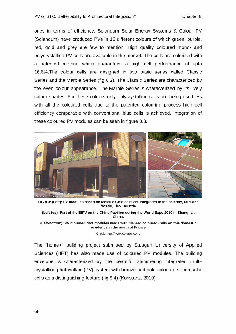
PV or STC: Better ability to Architectural Integration? Chapter 8
68
ones in terms of efficiency. Solandum Solar Energy Systems & Colour PV
(Solandum) have produced PVs in 15 different colours of which green, purple,
red, gold and grey are few to mention. High quality coloured mono- and
polycrystalline PV cells are available in the market. The cells are colorized with
a patented method which guarantees a high cell performance of upto
16.6%.The colour cells are designed in two basic series called Classic
Series and the Marble Series (fig 8.2). The Classic Series are characterized by
the even colour appearance. The Marble Series is characterized by its lively
colour shades. For these colours only polycrystalline cells are being used. As
with all the coloured cells due to the patented colouring process high cell
efficiency comparable with conventional blue cells is achieved. Integration of
these coloured PV modules can be seen in figure 8.3.
The "home+" building project submitted by Stuttgart University of Applied
Sciences (HFT) has also made use of coloured PV modules. The building
envelope is characterised by the beautiful shimmering integrated multi-
crystalline photovoltaic (PV) system with bronze and gold coloured silicon solar
cells as a distinguishing feature (fig 8.4) (Konstanz, 2010).
FIG 8.3: (Left): PV modules based on Metallic Gold cells are integrated in the balcony, rails and facade, Tirol, Austria
(Left-top): Part of the BIPV on the China Pavilion during the World Expo 2010 in Shanghai, China.
(Left-bottom): PV mounted roof modules made with tile Red coloured Cells on this domestic residence in the south of France
Credit: http://www.colorpv.com/
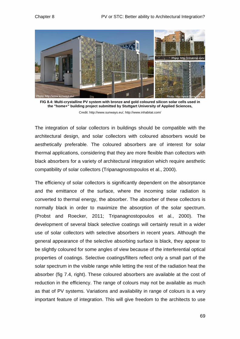
Chapter 8 PV or STC: Better ability to Architectural Integration?
69
The integration of solar collectors in buildings should be compatible with the
architectural design, and solar collectors with coloured absorbers would be
aesthetically preferable. The coloured absorbers are of interest for solar
thermal applications, considering that they are more flexible than collectors with
black absorbers for a variety of architectural integration which require aesthetic
compatibility of solar collectors (Tripanagnostopoulos et al., 2000).
The efficiency of solar collectors is significantly dependent on the absorptance
and the emittance of the surface, where the incoming solar radiation is
converted to thermal energy, the absorber. The absorber of these collectors is
normally black in order to maximize the absorption of the solar spectrum.
(Probst and Roecker, 2011; Tripanagnostopoulos et al., 2000). The
development of several black selective coatings will certainly result in a wider
use of solar collectors with selective absorbers in recent years. Although the
general appearance of the selective absorbing surface is black, they appear to
be slightly coloured for some angles of view because of the interferential optical
properties of coatings. Selective coatings/filters reflect only a small part of the
solar spectrum in the visible range while letting the rest of the radiation heat the
absorber (fig 7.4, right). These coloured absorbers are available at the cost of
reduction in the efficiency. The range of colours may not be available as much
as that of PV systems. Variations and availability in range of colours is a very
important feature of integration. This will give freedom to the architects to use
FIG 8.4: Multi-crystalline PV system with bronze and gold coloured silicon solar cells used in the "home+" building project submitted by Stuttgart University of Applied Sciences,
Credit: http://www.sunways.eu/, http://www.inhabitat.com/
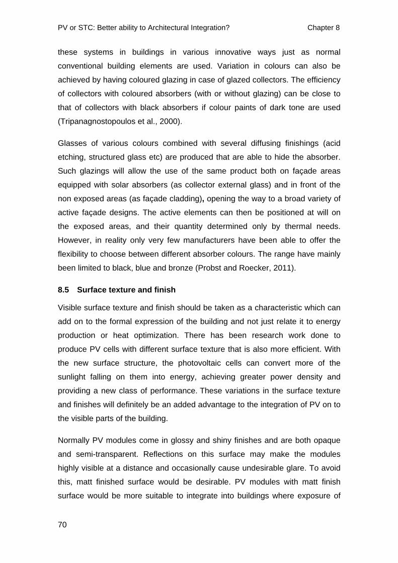
PV or STC: Better ability to Architectural Integration? Chapter 8
70
these systems in buildings in various innovative ways just as normal
conventional building elements are used. Variation in colours can also be
achieved by having coloured glazing in case of glazed collectors. The efficiency
of collectors with coloured absorbers (with or without glazing) can be close to
that of collectors with black absorbers if colour paints of dark tone are used
(Tripanagnostopoulos et al., 2000).
Glasses of various colours combined with several diffusing finishings (acid
etching, structured glass etc) are produced that are able to hide the absorber.
Such glazings will allow the use of the same product both on façade areas
equipped with solar absorbers (as collector external glass) and in front of the
non exposed areas (as façade cladding), opening the way to a broad variety of
active façade designs. The active elements can then be positioned at will on
the exposed areas, and their quantity determined only by thermal needs.
However, in reality only very few manufacturers have been able to offer the
flexibility to choose between different absorber colours. The range have mainly
been limited to black, blue and bronze (Probst and Roecker, 2011).
8.5 Surface texture and finish
Visible surface texture and finish should be taken as a characteristic which can
add on to the formal expression of the building and not just relate it to energy
production or heat optimization. There has been research work done to
produce PV cells with different surface texture that is also more efficient. With
the new surface structure, the photovoltaic cells can convert more of the
sunlight falling on them into energy, achieving greater power density and
providing a new class of performance. These variations in the surface texture
and finishes will definitely be an added advantage to the integration of PV on to
the visible parts of the building.
Normally PV modules come in glossy and shiny finishes and are both opaque
and semi-transparent. Reflections on this surface may make the modules
highly visible at a distance and occasionally cause undesirable glare. To avoid
this, matt finished surface would be desirable. PV modules with matt finish
surface would be more suitable to integrate into buildings where exposure of
Chapter 8 PV or STC: Better ability to Architectural Integration?
71
traditional building materials like brick, render of roof tiles and so on. Usually
structured glass is used as glass cover to give a matt finish (Hermannsdorfer
and Rub, 2005). The PV cell texture depends on different technology. Mono-
crystalline have a more solid finish while poly-crystalline cells have marble-like
texture(Farkas, Formal characteristics of Photovoltaics and their architectural
expression).
The absorbers of the STC also have variations in terms of surface texture and
finish. These are available from corrugated, embossed, perforated, regular and
irregular in terms of surface geometry. Evacuated tube collectors have exposed
glass tubes. The surface is matt, glossy or structured finishes (Probst and
Roecker, 2011). The glazing above the absorbers in case of glazed STC
systems may shine when sunlight falls on the surface and glare could be a
problem. Also, the variations in the surface texture and finish inside the glass
covering may not be visible from the outside. However, they can be well
integrated to complement with the glass surface of the façade or even roof. In
case of unglazed STC, the absorber surface texture and finish is clearly visible
and hence can be an option concerning possible patterns on the envelop they
are laid to.
With the above mentioned characteristics, PV modules have the flexibility to be
integrated both into opaque and transparent facades and roofs. When mounted
on a glass-glass module, the PV cells can be freely spaced achieving various
designs and pattern and can be best suited in atrium, glazed facades, canopy,
and verandah applications. Flat plate solar thermal collectors with their opaque
nature can only be integrated into the opaque parts of façade and roof (Probst
and Roecker, 2011).
8.6 Visible Jointing of Modules
Jointing between different PV or STC modules has an important influence on
the integration quality. The jointing are usually observable and hence must be
similar to the jointing of other cladding material on the same surface for
uniformity. PV systems with their slim thickness can be clad on to both opaque
and transparent facades similar to the installation of conventional cladding with
normal jointing. It is comparatively easier to achieve similar modular jointing
PV or STC: Better ability to Architectural Integration? Chapter 8
72
grid to that of other cladding used on the façade in case of PV modules. It is
equally possible to achieve sized fitting with the modular rhythm of the standard
cladding with the same type of jointing in STC systems as it is easier with PV
systems. However, to achieve jointing appearance similar to that of the other
claddings used on the same façade or sloped roof, custom design modules
have to be used in most cases.
8.7 Multi-functionality
A building’s external envelop must not only keep out water and regulate heat
loss, it must also regulate the entry of light, provide a sound barrier, offer ease
of technical maintenance and also must be aesthetically and architecturally
satisfying (Voss et al.) . One of the most important features of integration of PV
and STC systems is their possibility to use them not only as energy generators
but also as a replacement to other conventional building elements on the
external envelop and adding on to the overall expression of the building. PV
systems can be used as multifunctional elements in a more diverse form while
STC systems have some limitations in this aspect. Both PV and STC systems
can be used in place of normal building components with their multifunctional
potential as external skin for insulation, waterproofing, fire protection, wind
protection, acoustic control and shading (Fuentes, 2007). The STC systems
with their bulkier, rigid shapes and greater thickness may not be that easy to
integrate as sun shading and cladding on facades. Although daylight control
with the use of semi-transparent PV systems is possible, fulfilling the same
purpose with the use STC systems is only in the research state.
The use of PV cells on the south-facing glass façade of the 1960s
administrative building on the Stadtwerke Aachen in Germany was one of the
first multipurpose applications with PV modules (fig 8.5). This was conceived
during renovation in 1991. Light-diffusing modules developed especially for this
south-east front direct daylight into the staircase behind. The chessboard type
combination of glass elements and the modules with dark-blue crystalline
silicon cells between the compound glazing offered surprising patterns both
outside as well as inside. The PV modules act as semitransparent façade
providing sun protection, as wall element including thermal insulation in

Chapter 8 PV or STC: Better ability to Architectural Integration?
73
addition to power production. The cabling is completely integrated into the
metal frames of the façade (Hermannsdorfer and Rub, 2005; Lundgren and
Torstensson, 2004).
The use of STC system was conceived from the beginning in the housing at
Bjoernveien, Oslo (fig 8.6). Solar collectors have been incorporated into the
southern façade as multifunctional cladding elements. These attractive
collectors with dark, reflecting surfaces in addition to producing energy also act
as a sound barrier for road traffic (SHC).
The following points may not be directly related to architectural integration but
relevant to be considered while making a choice for integration.
FIG 8.6: Multifunctional use of STC systems in the façade of the housing in Bjoernveien, Oslo, Credit: http://www.archdaily.com/
FIG 8.5: One of the first applications of the multifunctional use of PV systems in the administrative building on the Stadtwerke, Aachen, Germany,
Credit: Solar Design
PV or STC: Better ability to Architectural Integration? Chapter 8
74
8.8 Transportation of Energy
Transportation of electricity is easier than water. For the transfer of hot water,
the pipes must be insulated and the temperature of water drops with the length
of the pipes. So, hot water cannot be transported over long distances. In the
case of electricity generated by PV systems, they can be transmitted over long
distances similar to the normal grid over wires with negligible transmission loss.
As a result, the energy production does not have to be close to the
consumption area (Hestnes, 2012). However, the scope of the thesis is that
each house has its own energy generator integrated; be it STC or PV systems.
In cases when there are difficulties to integrate PV and STC systems in the
building then of course, they can be placed somewhere else. This is usually
done if the integration happens to ruin the appearance of the building or is not
permitted by the bylaws. For eg, in historically important buildings when bylaws
don’t permit; they could be placed somewhere else other than the building.
8.9 Storage
As the nature of the energy produced by PV and STC systems is different, the
need for energy storage also varies. The electricity produced by the PV
modules can be stored in batteries or fed into the grids. With this the sizing of
the system is totally independent of the local consumption, and the energy
produced can be much more than that needed by the building. However, the
heat produced by the STC has to be stored in tanks which of course are limited
in terms of storage capacity. Besides, STC are sensitive to damages resulting
from overheating. As a result, the heat production ideally should not exceed the
storage capacity (Probst and Roecker, 2011).
Because of the difference in principle and size in storage of these two systems,
STC systems should be dimensioned according to the specific building needs
and the total storage tank capacity, to avoid overheating and the accompanying
overheating problems. PV are totally independent of the building energy needs
and can be dimensioned according to the size of available exposed areas, or
according to architectural criteria (Probst and Roecker, 2011).
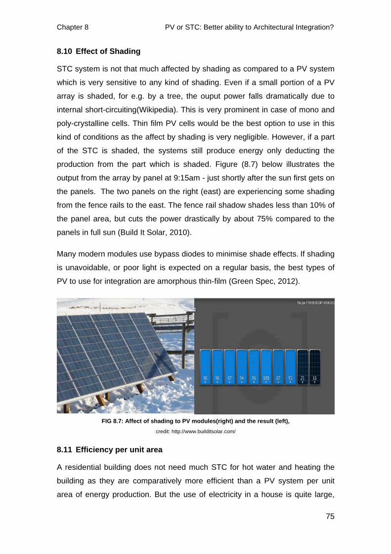
Chapter 8 PV or STC: Better ability to Architectural Integration?
75
8.10 Effect of Shading
STC system is not that much affected by shading as compared to a PV system
which is very sensitive to any kind of shading. Even if a small portion of a PV
array is shaded, for e.g. by a tree, the ouput power falls dramatically due to
internal short-circuiting(Wikipedia). This is very prominent in case of mono and
poly-crystalline cells. Thin film PV cells would be the best option to use in this
kind of conditions as the affect by shading is very negligible. However, if a part
of the STC is shaded, the systems still produce energy only deducting the
production from the part which is shaded. Figure (8.7) below illustrates the
output from the array by panel at 9:15am - just shortly after the sun first gets on
the panels. The two panels on the right (east) are experiencing some shading
from the fence rails to the east. The fence rail shadow shades less than 10% of
the panel area, but cuts the power drastically by about 75% compared to the
panels in full sun (Build It Solar, 2010).
Many modern modules use bypass diodes to minimise shade effects. If shading
is unavoidable, or poor light is expected on a regular basis, the best types of
PV to use for integration are amorphous thin-film (Green Spec, 2012).
8.11 Efficiency per unit area
A residential building does not need much STC for hot water and heating the
building as they are comparatively more efficient than a PV system per unit
area of energy production. But the use of electricity in a house is quite large,
FIG 8.7: Affect of shading to PV modules(right) and the result (left), credit: http://www.builditsolar.com/
PV or STC: Better ability to Architectural Integration? Chapter 8
76
and hence the PV systems cover a large part of the area for more production.
PV panels run about 8-20% efficient at converting sunlight into electricity, and
this efficiency goes down as the panel gets warmer. Unlike the PV systems,
even moderate quality flat-plate thermal collectors operate at about 65 to 70%
efficiency when the fluid running through them is not a lot hotter than ambient
temperature. And this efficiency stays high as the day heats up and water also
heats up. Once the heating target is hot or if the ambient temperature is very
cold, collector efficiency declines according to a very predictable slope.
Thermal collector ratings are performed by an independent testing agency
however there is no equivalent third-party testing for photovoltaic equipment
(SolarConsultants, 2009).
8.12 Useful life time
The useful life time of PV systems is much longer and the maintenance
requirement is quite less as compared to STC systems. In general, PV systems
that are well designed and properly installed require minimal maintenance and
have long service lifetimes. PV systems keep on functioning for as long as
thirty years while STC systems may function only upto 15 years (Green Spec,
2012). The STC systems have pipes and corroding parts due to flowing liquid
unlike in a PV system that only has connecting wires. This accounts for the
shorter life time in case STC systems. So, with the PV systems having a longer
useful life could be used in place of other conventional cladding elements on
roofs and facade.
8.13 Temperature
The higher the temperature rise, the better the efficiency of the solar thermal
energy system (Catch Solar, 2012). But this is not the case with PV systems.
Temperature rise is inversely proportional to the production efficiency of PV
panels, i.e. higher the temperature of the panels, lower is the output (REUK).
Hence, this fact must be considered while integrating these systems into
buildings so that maximum output is achieved by careful consideration of
minimizing self heating of the systems. PV modules should be back-ventilated
for higher efficiency while solar thermal absorbers require back-insulation to
minimize heat losses. Integrating the collectors directly in the building envelop
Chapter 8 PV or STC: Better ability to Architectural Integration?
77
layers, possibly without an air gap is ideal in this sense for solar thermal
systems, while freestanding or ventilated applications would be preferable for
PV (Probst and Roecker, 2011).
The performance of PV modules decreases with increasing temperature and
the drop in performance is more significant for crystalline silicon than
amorphous silicon (SEAI). Designs for building-integrated PVs need to
consider this from the outset in order to allow air to flow over the backs of the
modules to cool and maintain high performance. It is also necessary with all
types of module to avoid unwanted heat gain into the occupied space that
could cause discomfort and increase any cooling load.
Building integrated modules can reach 20-40°C above ambient in conditions of
high radiation. For each 10°C increase in cell temperature above 25°C the
power output decreases by about 0.4-0.5% (SEAI). It is therefore important to
ensure excessive temperature is avoided as far as possible.
8.14 Cost
Leaving tax credits and incentives out of the figures, for each kilowatt-hour of
electricity produced, a typical PV system costs much more than the solar
thermal collector systems (SolarConsultants, 2009). The study made by Ben
Croxford and Kat Scott have found out that the STC systems are superior to PV
systems in terms of installation cost, annual saving, maintenance and payback.
The carbon payback for the solar thermal system is 2 years and for BIPV, it is
around 6 years (Croxford and Scott).
Looking at the current trend of falling price of PV systems, at some point in the
future, if the price happens to be even lower than the price of the collectors, PV
produced electricity could also be used to heat water and space. However, we
must also consider resource use and embodied energy for the manufacture of
these two systems. Croxford and Scott in their study have found out that the
embodied energy of PV system is larger compared to STC systems. Among the
two, the one that is more resource friendly should of course be considered.
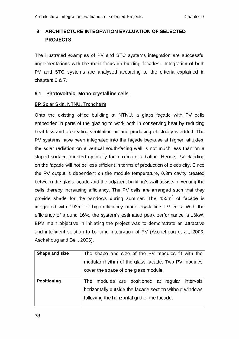
Architectural Integration evaluation of selected Projects Chapter 9
78
9 ARCHITECTURE INTEGRATION EVALUATION OF SELECTED PROJECTS
The illustrated examples of PV and STC systems integration are successful
implementations with the main focus on building facades. Integration of both
PV and STC systems are analysed according to the criteria explained in
chapters 6 & 7.
9.1 Photovoltaic: Mono-crystalline cells
BP Solar Skin, NTNU, Trondheim
Onto the existing office building at NTNU, a glass façade with PV cells
embedded in parts of the glazing to work both in conserving heat by reducing
heat loss and preheating ventilation air and producing electricity is added. The
PV systems have been integrated into the façade because at higher latitudes,
the solar radiation on a vertical south-facing wall is not much less than on a
sloped surface oriented optimally for maximum radiation. Hence, PV cladding
on the façade will not be less efficient in terms of production of electricity. Since
the PV output is dependent on the module temperature, 0.8m cavity created
between the glass façade and the adjacent building’s wall assists in venting the
cells thereby increasing efficiency. The PV cells are arranged such that they
provide shade for the windows during summer. The 455m2 of façade is
integrated with 192m2 of high-efficiency mono crystalline PV cells. With the
efficiency of around 16%, the system’s estimated peak performance is 16kW.
BP’s main objective in initiating the project was to demonstrate an attractive
and intelligent solution to building integration of PV (Aschehoug et al., 2003;
Aschehoug and Bell, 2006).
Shape and size The shape and size of the PV modules fit with the
modular rhythm of the glass facade. Two PV modules
cover the space of one glass module.
Positioning The modules are positioned at regular intervals
horizontally outside the facade section without windows
following the horizontal grid of the facade.
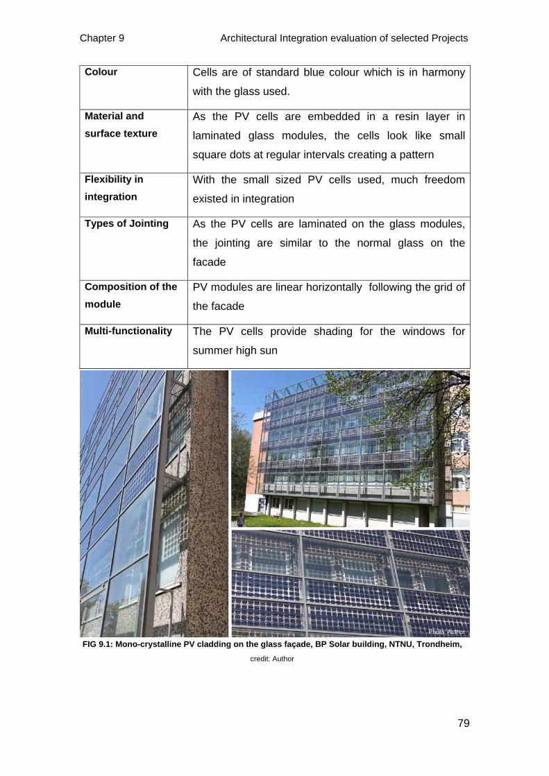
Chapter 9 Architectural Integration evaluation of selected Projects
79
Colour Cells are of standard blue colour which is in harmony
with the glass used.
Material and surface texture
As the PV cells are embedded in a resin layer in
laminated glass modules, the cells look like small
square dots at regular intervals creating a pattern
Flexibility in integration
With the small sized PV cells used, much freedom
existed in integration
Types of Jointing As the PV cells are laminated on the glass modules,
the jointing are similar to the normal glass on the
facade
Composition of the module
PV modules are linear horizontally following the grid of
the facade
Multi-functionality The PV cells provide shading for the windows for
summer high sun
FIG 9.1: Mono-crystalline PV cladding on the glass façade, BP Solar building, NTNU, Trondheim, credit: Author
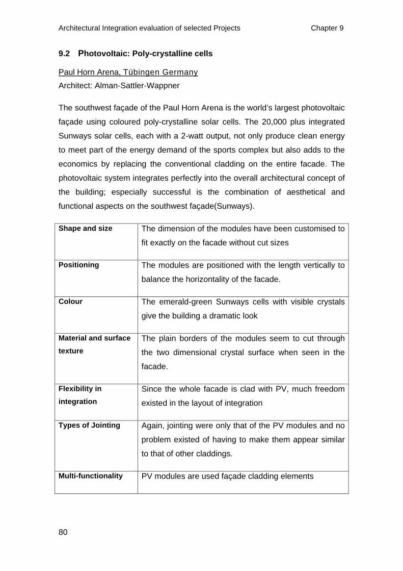
Architectural Integration evaluation of selected Projects Chapter 9
80
9.2 Photovoltaic: Poly-crystalline cells
Paul Horn Arena, Tübingen Germany Architect: Alman-Sattler-Wappner
The southwest façade of the Paul Horn Arena is the world’s largest photovoltaic
façade using coloured poly-crystalline solar cells. The 20,000 plus integrated
Sunways solar cells, each with a 2-watt output, not only produce clean energy
to meet part of the energy demand of the sports complex but also adds to the
economics by replacing the conventional cladding on the entire facade. The
photovoltaic system integrates perfectly into the overall architectural concept of
the building; especially successful is the combination of aesthetical and
functional aspects on the southwest façade(Sunways).
Shape and size The dimension of the modules have been customised to
fit exactly on the facade without cut sizes
Positioning The modules are positioned with the length vertically to
balance the horizontality of the facade.
Colour The emerald-green Sunways cells with visible crystals
give the building a dramatic look
Material and surface texture
The plain borders of the modules seem to cut through
the two dimensional crystal surface when seen in the
facade.
Flexibility in integration
Since the whole facade is clad with PV, much freedom
existed in the layout of integration
Types of Jointing Again, jointing were only that of the PV modules and no
problem existed of having to make them appear similar
to that of other claddings.
Multi-functionality PV modules are used façade cladding elements
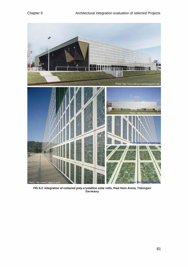
Chapter 9 Architectural Integration evaluation of selected Projects
81
FIG 9.2: Integration of coloured poly-crystalline solar cells, Paul Horn Arena, Tübingen Germany
Architectural Integration evaluation of selected Projects Chapter 9
82
9.3 Photovoltaic: Thin-film cells
Dwelling houses Spinnereistraße Architect: Kaufmann Hermann
The movable Photovoltaic panels used on the south side of the facade which
serve also as sun shades are the most remarkable feature of this house. On
the northern side dummy modules have been used of the same blue colour as
the PV modules. In combination with the bright wooden exterior cladding of the
building the sliding shutters adds on to the facade composition. The effect of
the interior quality is also controllable with the moving solar shades that are
glued onto the aluminium sliding elements (Kaufmann, 2003).
Shape and size Modular dimension is the result of the floor height and
the window width
Positioning The modules are positioned such that they can shade
each windows whenever necessary by sliding
Colour The blue colour PV modules are in contrast to the
timber facade cladding but look like windows even when
the windows are covered
Material and surface texture
The glassy look of the modules makes them appear as
windows. Thin white horizontal lines is also noticeable
Flexibility in integration
Use of same sized modules make the integration more
flexible and economical
Jointing PV modules are glued on the aluminium sliding element
similar to any conventional sliding panel.
Multi-functionality PV modules act as shading devices
Dummy elements Dummies are available
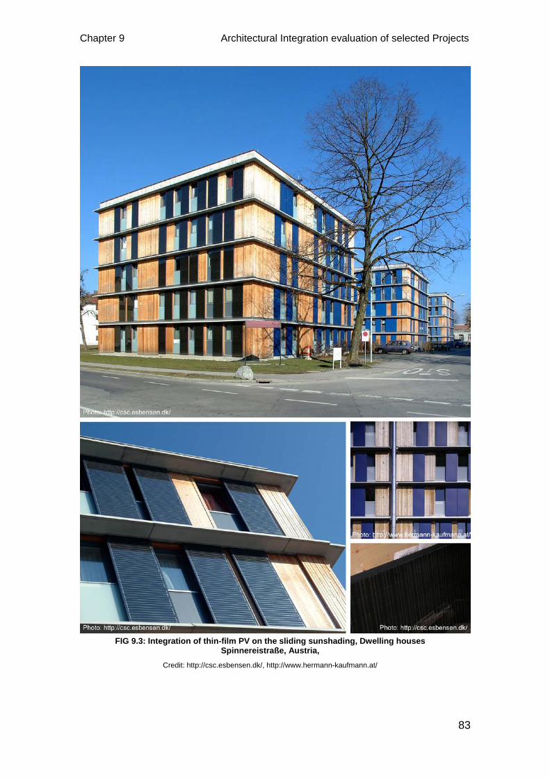
Chapter 9 Architectural Integration evaluation of selected Projects
83
FIG 9.3: Integration of thin-film PV on the sliding sunshading, Dwelling houses Spinnereistraße, Austria,
Credit: http://csc.esbensen.dk/, http://www.hermann-kaufmann.at/
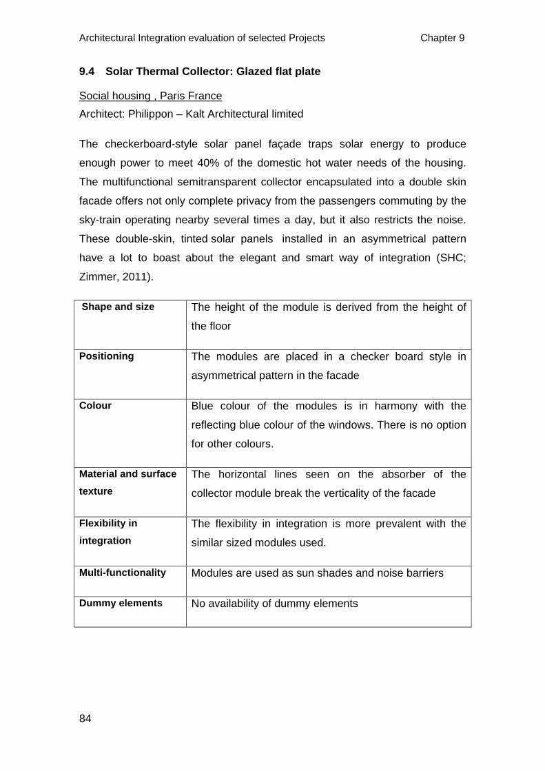
Architectural Integration evaluation of selected Projects Chapter 9
84
9.4 Solar Thermal Collector: Glazed flat plate
Social housing , Paris France Architect: Philippon – Kalt Architectural limited
The checkerboard-style solar panel façade traps solar energy to produce
enough power to meet 40% of the domestic hot water needs of the housing.
The multifunctional semitransparent collector encapsulated into a double skin
facade offers not only complete privacy from the passengers commuting by the
sky-train operating nearby several times a day, but it also restricts the noise.
These double-skin, tinted solar panels installed in an asymmetrical pattern
have a lot to boast about the elegant and smart way of integration (SHC;
Zimmer, 2011).
Shape and size The height of the module is derived from the height of
the floor
Positioning The modules are placed in a checker board style in
asymmetrical pattern in the facade
Colour Blue colour of the modules is in harmony with the
reflecting blue colour of the windows. There is no option
for other colours.
Material and surface texture
The horizontal lines seen on the absorber of the
collector module break the verticality of the facade
Flexibility in integration
The flexibility in integration is more prevalent with the
similar sized modules used.
Multi-functionality Modules are used as sun shades and noise barriers
Dummy elements No availability of dummy elements
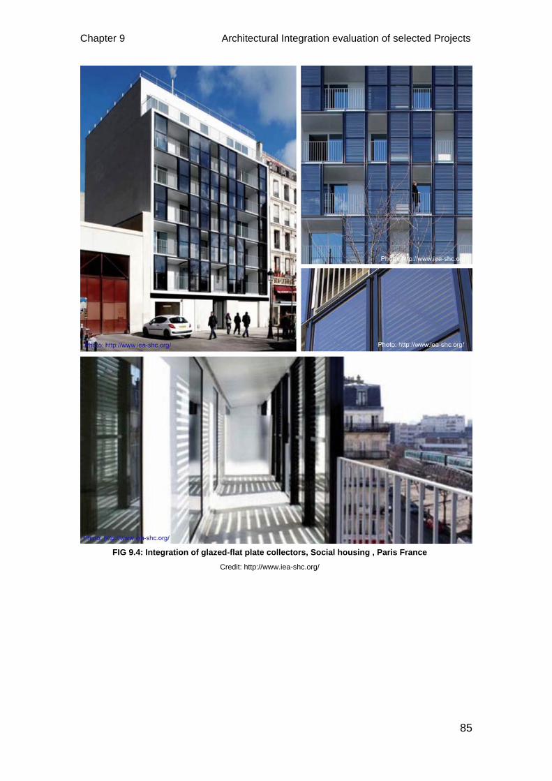
Chapter 9 Architectural Integration evaluation of selected Projects
85
FIG 9.4: Integration of glazed-flat plate collectors, Social housing , Paris France Credit: http://www.iea-shc.org/

Architectural Integration evaluation of selected Projects Chapter 9
86
9.5 Solar thermal collectors: Vacuum tubes
Sunny Woods, Switzerland Architect: Beat Kampfen, Regensdorferstrasse
The apartment complex is designed as an energy effective, passive house with
PV modules on the roof for necessary energy to run the electrical equipment
and solar thermal collectors for hot water. For the first time vacuum tube solar
thermal collectors were integrated as an architectural element used as balcony
balustrades in the south facade (Kjellerup et al., 2010). The 90 cm high solar
module balustrades that look like normal handrails are a stack of nine long
glass tubes. Inside each of these glass tubes, a finger-thick pipe with a metal
absorber transports water. The collector as a whole is oriented vertically, but
each absorber is turned to an optimum angle of about 55° toward the sun, to
collect the maximum energy in the fall and spring. If the solar collectors were
pitched, too much energy would be produced in the summer and too little in the
other seasons. Each of these 18 solar collector modular balconies very much
characterize the formal composition of the tiber clad facade (Probst and
Roecker, 2011). Beside the energy advantage and balcony fencing, the solar
collectors create aesthetic value by throwing a changing pattern of light and
shadow on the floors of the rooms.
Shape and size Collector modules each with nine evacuated tubes are
dimensioned as standard balcony parapet
Positioning The modules are positioned at regular intervals in the
facade
Colour Standard reflecting blue colour is in harmony with the
colour of the background glazing
Material and surface texture
The horizontal lines created by the solar tubes
characterise the horizontal lines of the timber cladding
Flexibility in integration
With the use of evacuated tube collectors, much
flexibility was possible for integration
Multi-functionality The collector modules are used as balcony railing
Chapter 9 Architectural Integration evaluation of selected Projects
87
FIG 9.5: Integration of evacuated collectors as balcony railings, Sunny Woods, Switzerland
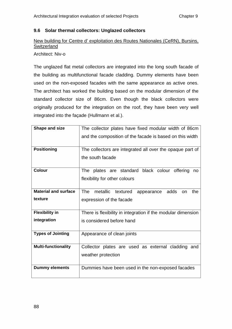
Architectural Integration evaluation of selected Projects Chapter 9
88
9.6 Solar thermal collectors: Unglazed collectors
New building for Centre d’ exploitation des Routes Nationales (CeRN), Bursins, Switzerland Architect: Niv-o
The unglazed flat metal collectors are integrated into the long south facade of
the building as multifunctional facade cladding. Dummy elements have been
used on the non-exposed facades with the same appearance as active ones.
The architect has worked the building based on the modular dimension of the
standard collector size of 86cm. Even though the black collectors were
originally produced for the integration on the roof, they have been very well
integrated into the façade (Hullmann et al.).
Shape and size The collector plates have fixed modular width of 86cm
and the composition of the facade is based on this width
Positioning The collectors are integrated all over the opaque part of
the south facade
Colour The plates are standard black colour offering no
flexibility for other colours
Material and surface texture
The metallic textured appearance adds on the
expression of the facade
Flexibility in integration
There is flexibility in integration if the modular dimension
is considered before hand
Types of Jointing Appearance of clean joints
Multi-functionality Collector plates are used as external cladding and
weather protection
Dummy elements Dummies have been used in the non-exposed facades
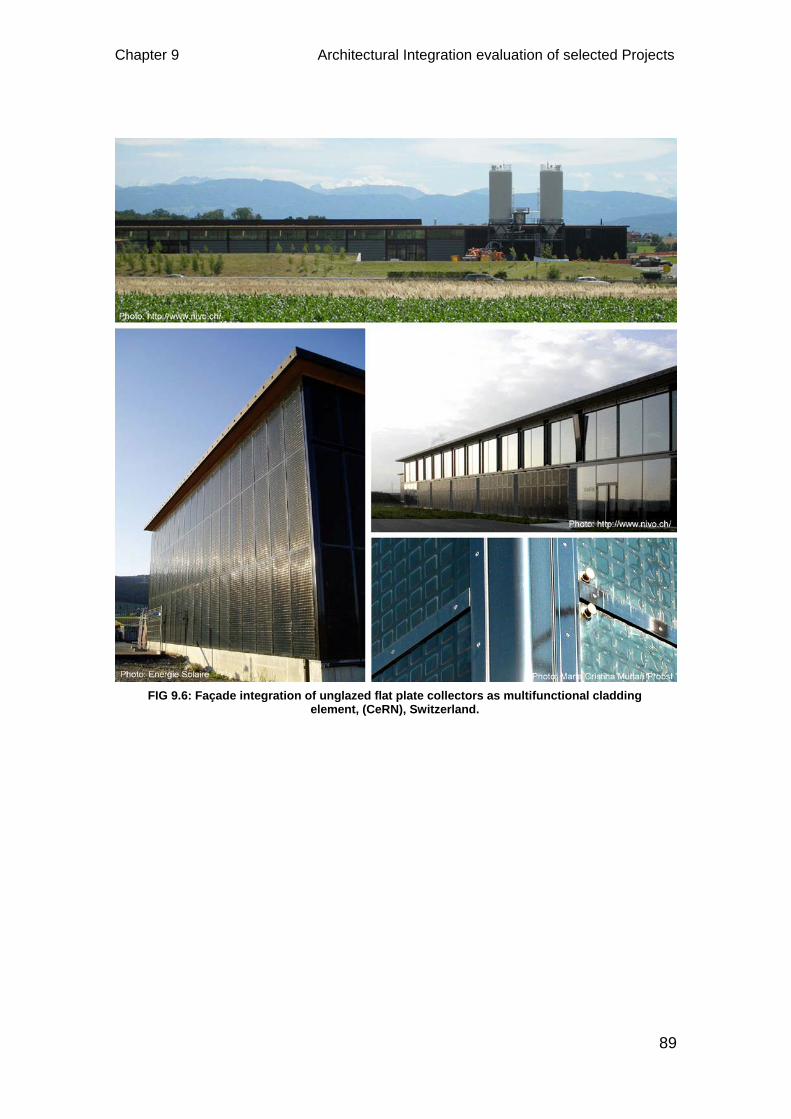
Chapter 9 Architectural Integration evaluation of selected Projects
89
FIG 9.6: Façade integration of unglazed flat plate collectors as multifunctional cladding element, (CeRN), Switzerland.
Conclusion Chapter 10
90
10 CONCLUSION
With an aim to look for different possible ways of integrating PV and STC
systems giving more emphasis to the formal aspects, the thesis has tried to
investigate on relevant methods and requirements to achieve quality in
integration. Starting with a brief introduction on the present scenario of energy
crisis and hazards related to the use of fossil fuel was an attempt to emphasize
on the relevance of using renewable energy especially that from the sun which
is very abundantly available that too for free.
PV and STC systems were developed as pure technical elements to make use
of solar energy to produce electricity and heat respectively. However, it is
realized that without developing these solar elements as some part of the
building element and make them acceptable, their utilization in buildings will
certainly not develop in terms of quality integration. They will still remain as
pure technical additions into the building only fulfilling energy requirements and
often ruining the overall architectural expression of the building.
The thesis has made an attempt to understand building and architectural
integration and underline their differences. It is possible and logical to integrate
PV and STC systems into the external building envelop as multifunctional
elements which will in addition improve on the aesthetics. Visible parts of the
roof and façade are best suited for this kind of integration. There must be some
guidelines or criteria that are to be followed to achieve quality and homogeneity
in the integration process which has been described and explored. With these
guidelines in mind, some sort of comparison has been made on the integration
abilities of both the PV and STC systems. This comparative study is done
mainly to give a general overview as to which systems among to two would
best suit for particular building integration according to energy needs, site
conditions, location, position on the façade or roof and architectural
expressions.
To summarize the study, it can be said that PV and STC are very important
active systems to produce green and clean energy using sunlight and can be
developed as fundamental parts of the building envelop with added aesthetics
Chapter 10 Conclusion
91
to the building. When these systems are considered very early in the design,
they can perform very well both technically and aesthetically. The overall
reduction in construction cost resulting from the multifunctional use of these
systems is another important feature of integration. However, with the
availability of less PV and STC systems that can be well integrated into the
building envelop, it becomes equally important to develop systems into a more
‘integrable’ form similar to other building elements. So, designers and
manufacturers have a role to play in this regards. STC systems have slightly
less ‘integrable’ ability than the PV systems, so needs special considerations
during design and manufacture for architectural integration in terms of size and
position, colour, surface texture and materials and module jointing.
Last but not the least, Integration of PV and STC systems into the building as
multifunctional building envelop will not only produce renewable energy for
building needs but will also add value to the overall building by enriching the
architectural expression, thereby increasing its marketability. Also, integration
process must be developed in such a way that it is acceptable by people so
that in the coming days, more buildings will have PV and STC systems well
integrated and not used only as mere technical elements.
References
92
REFERENCES
Archibald, J. Building Integrated Solar Thermal Roofing systems History, current status, and Future Promise. Available: http://americansolar.com/resources/papers/solar99.pdf [Accessed 23 April, 2012].
Aschehoug, Ø., Hestnes, A. G. & Wyckmans, A. 2003. BP Solar Skin - A facade concept for a sustainable future. Internation Solar Energy Conference ISES. Goteborg, Sweden.
Behling, S. & Hieber, J. Solar Thermal Tubes in the Facade [Online]. Available: http://www.paradigma-iberica.es/descargas/sistema_de_fachadas_con_tubos_cpc.pdf [Accessed 28 April, 2012].
Build It Solar. 2010. Partial shading of PV Array [Online]. Available: http://www.builditsolar.com/Projects/PV/EnphasePV/Shading.htm [Accessed 20 April 2012].
Catch Solar. 2012. Award winning solar collector [Online]. Available: http://www.catchsolar.net/pages/solar_energy_temperature_measurements.php [Accessed 10 May, 2012].
CBD Energy. CBD Solar [Online].
Available: http://www.cbdenergy.com.au/customised_more.html.
Croxford, B. & Scott, K. Can PV or Solar Thermal Systems be cost effective ways of reducing CO2 emissions for residential buildings? Available: http://eprints.ucl.ac.uk/2642/1/2642.pdf [Accessed 22 April, 2012].
EAESL. Solar thermal systems [Online]. Available: http://www.daviddarling.info/encyclopedia/F/AE_flat_plate_solar_thermal_collector.html [Accessed 12 March, 2012].
EAESL. Transpired air collector [Online]. Available: http://www.daviddarling.info/encyclopedia/T/AE_transpired_air_collector.html [Accessed 10 April, 2012].
EERE. The History of Solar. Available: http://www1.eere.energy.gov/solar/pdfs/solar_timeline.pdf [Accessed 12 April, 2012].
EST. 2006. Major photovoltaic demonstration program [Online]. Available: http://www.pvdatabase.org/pdf/VauxhallCrossTransportInterchange.pdf [Accessed 08 March, 2012].
Farkas, K. Facade Integration Typologies of Photovoltaics.
Farkas, K. Formal characteristics of Photovoltaics and their architectural expression.
Foster, R., Ghassemi, M. & Cota, A. 2009. Solar Energy, CRC Press, pp.73-114.
References
93
Fthenakis, V. M., Kim, H. C. & Alsema, E. 2008. Emissions from Photovoltaic Life Cycles. Environmental Science & Technology, 42, 2168-2174, pp.2168-2174.
Fuentes, M. 2007. Integration of PV into the built environment. Available: http://www.brita-in-pubs.eu/bit/uk/03viewer/retrofit_measures/pdf/FINAL_12_Integration_of_PV_red_kth_rev1.pdf [Accessed 15 March, 2012].
Green Spec. 2012. Photo Voltaic (PV) cells [Online]. Available: http://www.greenspec.co.uk/pv-cells.php [Accessed 5 May, 2012].
Hermannsdorfer, I. & Rub, C. 2005. Solar Design, Berlin, Jovis Verlag GmbH.
Hestnes, A. G. 1999. Building Integration Of Solar Energy Systems. Solar Energy, 67, 181-187, pp.181-187.
Hestnes, A. G. 2012. Discussion on building and architectural integration. (Personal communication, 23 March, 2012)
Horizon Renewables. 2010. Solar Photovoltaics & Wind Turbines for homes, farms, schools, commercial and public sector in UK [Online]. Available: http://www.horizonrenewables.co.uk/ [Accessed 25 March, 2012].
Horvat, M., Dubois, M.-C., Snow, M. & Wall, M. (eds.) IEA Task 41: Solar Energy and Architecture.
Huan, P. Q. (ed.) 2011. Handbook for Green Housing.
Hullmann, Willkomm & partner. The stainless steel solar façade of a highway maintenance building at Bursins, Switzerland [Online]. Available: http://www.nivo.ch/CeRN_EN.pdf [Accessed 02 May, 2012].
Kalogirou, S. A. 2004. Solar thermal collectors and applications. Progress in Energy and Combustion Science, 30, 231-295, pp.231-295.
Kaufmann, H. 2003. Spinnereistraße [Online]. Available: http://www.hermann-kaufmann.at/v2-1.php?oid=00_99 [Accessed 12 May, 2012].
Kjellerup, U. F., Sander, K., Windeleff, J., Hestnes, A. G., Kappel, K. & Esbensen, T. (eds.) 2010. Solar Heating + Architecture.
Konstanz. 2010. Solar architecture with building-integrated photovoltaics from Sunways receives award [Online]. Available: http://www.sunways.eu/en/company/press/releases/PM_100811_Solardecathlon.html [Accessed 05 May, 2012].
Lundgren, M. & Torstensson, K. 2004. Photovoltaics in Architecture - lessons learned in PV Nord. Available: http://www.pvnord.org/results/downloads/PVarchitects050121.pdf [Accessed 20 February, 2012].
M9 Architects. 2009. State Vocational School [Online]. Available: http://www.m9-architekten.at/projekte/2001_imst-landesberufsschule/index.html [Accessed 20 April, 2012].
References
94
Munari Probst, M. C., Schueler, A., De Chambrier, E. & Roecker, C. 2007. Facade Integration of Solar Thermal Collectors: Present and Future. CISBAT International Conference. Lausanne, Switzerland.
Munari Probst, M. C., Schueler, A. & Roecker, C. 2010. Bringing colours to solar collectors: a contribution to an increased building "integrability". Colour & Light in Architectecture. Venice, Italy.
New4old. Integration of solar thermal collectors [Online]. Available: http://www.new4old.eu/guidelines/C6_Part1_H5.html [Accessed 25 April, 2012].
Odersun. 2011. Manual for BIPV Projects. Available: http://www.odersun.com/uploads/pdf/Odersun-BiPV%20Manual-110902-EN-Download.pdf [Accessed 18 March, 2012].
Onyx Solar. 2012. Building Integrated Photovoltaics [Online]. Available: http://www.onyxsolar.com/projects/onyxsolar-bipv-projects.html [Accessed 20 April, 2012].
Phillips, D. 2000. Lighting Modern Buildings.
Probst, M. C. M. 2009. Architectural Integration and Design of Solar Thermal Systems. Ph.D.
Probst, M. C. M. & Roecker, C. 2011. Architectural Integration and Design of Solar Thermal Systems, Oxford, UK, Routledge Taylor and Francis Group.
PV Database. Urban scale photovoltaic systems [Online]. Available: http://www.pvdatabase.org/projects_view_details.php?ID=261 [Accessed 26 March, 2012].
Quality Domains Ltd. 2012. Solar PV - Solar PV louvres - Solar PV sun shades [Online]. Available: http://www.solarpv.co.uk/solar-pv-louvres.html [Accessed 21 April, 2012].
Reijenga, T. H. & Kaan, H. F. 2011. PV in Architecture. In: LUQUE, A. & HEDEDUS, S. (eds.) Handbook of Photovoltaic Science and Engineering. Second ed.: John Wiley & Sons.
REM. 2012. Techtile Therma [Online]. Available: http://www.remenergies.it/index.php?area=65&menu=47&page=831&lingua=1 [Accessed 10 May, 2012].
REUK. Effect of temperature on Solar Panels [Online]. Available: http://www.reuk.co.uk/Effect-of-Temperature-on-Solar-Panels.htm [Accessed 10 May, 2012].
Roberts, S. & Guariento, N. Building Integrated Photovoltaics / a handbook [Online]. Available: http://www.springerlink.com/content/978-3-7643-9948-1/?MUD=MP&sort=p_OnlineDate&sortorder=desc&o=10 [Accessed 12 March, 2012].
Roecker, C., Munari Probst, M. C., De Chambrier, E., Schueler, A. & Scartezzini, J.-L. 2007. Facade Integration of Solar Thermal Collectors:A Breakthrough?
References
95
SEAI. Best practice guide - Photovoltaics (PV) [Online]. Available: http://www.seai.ie/Publications/Renewables_Publications/Solar_Energy/Best_Practice_Guide_for_PV.pdf [Accessed 25 April, 2012].
SHC. Architectrual integration of solar thermal energy systems [Online]. Available: http://www.iea-shc.org/task39/projects/ [Accessed 25 April, 2012].
SHC. 2012. IEA SHC Task 41 Solar Energy and Architecture [Online]. Available: http://csc.esbensen.dk/ [Accessed 22 April, 2012].
Sohie, C. Integration of Photovoltaics in Architecture. Available: www.arupassociates.com/Photovoltaics.pdf [Accessed 15 March, 2012].
Sohie, C. Integration of photovoltaics in architecture. Photovoltaic Energy Conversion, 2003. Proceedings of 3rd World Conference on, 18-18 May 2003 2003. 2120-2124 Vol.3.
Solandum. Colour - PV [Online]. Available: http://www.colorpv.com/lof_eng/c_cellseries_eng.html [Accessed 12 May, 2012].
Solar, W. 2011. Three Photovoltaic Technologies: Monocrystalline, Polycrystalline and Thin Film [Online]. Available: http://www.wholesalesolar.com/Information-SolarFolder/celltypes.html [Accessed 15 March, 2012].
Solar Consultants. 2009. Comparison of solar thermal heating systems and photovoltaic systems [Online]. Available: http://www.solarconsultants.com/thermalPVComp.php [Accessed 5 May 2012].
Solar Fabrik. Zero emission factory [Online]. Available: http://www.solar-fabrik.de/press/press-service/press-photos/zero-emission-factory/?L=1 [Accessed 21 April, 2012].
Solar fassade. 2011. Format and colour [Online]. Available: http://www.solarfassade.info/en/fundamentals/components/format_colors.php [Accessed 12 May, 2012].
Solar plaza. 2009. Hybrid Solar Facade of Fiat Research Center (CRF) [Online]. Available: http://www.solarplaza.com/project/hybrid-solar-facade-of-fiat-research-centre-crf [Accessed 15 April, 2012].
Solstice energy. 2012. Pitched Roof [Online]. Available: http://www.solsticeenergy.co.uk/pitched-roof.htm [Accessed 24 April, 2012].
Stadler, I. Facade Integrated Solar Thermal Collectors. Available: http://www.aee-intec.at/0uploads/dateien19.pdf [Accessed 17th April, 2012].
Sunways. Paul Horn-Arena, Tubingen, Germany The venue for optimal solar performance [Online]. Available: http://www.sunways.eu/en/references/building-integration/paul-horn-arena/ [Accessed 11 May, 2012].
Thomas, R., Fordham, M. & Partners (eds.) 2001. Photovoltaics and Architecture, London: Spon Press.
References
96
Tripanagnostopoulos, Y., Souliotis, M. & Nousia, T. 2000. Solar collectors with colored absorbers. Solar Energy, 68, 343-356, pp.343-356.
Voss, K., Laukamp, H. & Ufheil, M. Photovoltaics for Buildings - Market, Technology, Archtecture, Energy Concepts. Available: http://www-cenerg.ensmp.fr/ease/photovoltaic.pdf [Accessed 08 April, 2012].
Wall, M. 2009. SHC Task 41 Solar Energy and Architecture
Available: http://www.iea-shc.org/publications/downloads/task41-Annex.pdf [Accessed 12 March, 2012].
Wikipedia. Photovoltaic system [Online]. Available: http://en.wikipedia.org/wiki/Photovoltaic_system [Accessed 15 May, 2012].
Wolter, N. 2003. Options for Integrating PV into Your Building. Available: http://www.ecw.org/wisconsun/learn/bipvoptions.pdf [Accessed 20 April, 2012].
Zimmer, L. 2011. Checkerboard solar-clad housing project pops up in Paris [Online]. Available: http://inhabitat.com/checkerboard-solar-clad-housing-project-pops-up-in-paris/ [Accessed 12 May, 2012].


![Performance of a PV/T Solar Collector in a Tropical ... · ... [7,8]. Os coletores PV/T ... o tubo e a placa absorvedora e o quinto is ao isolamento . ... (°C) 21,1 20,6 20,7 21,4](https://static.fdocuments.net/doc/165x107/5bfcc04409d3f2c11d8b963d/performance-of-a-pvt-solar-collector-in-a-tropical-78-os-coletores.jpg)