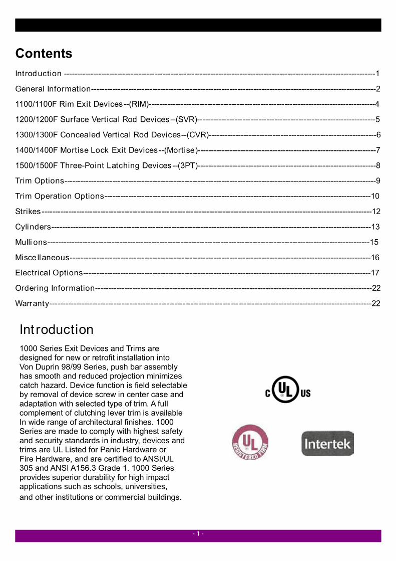
Architectural Hardware MFG - TownSteel Inc 3 - Dimensions Trims Hand of Doors
17
1000 Series Exit Devices TownSteel ® Architectural Hardware MFG
Transcript of Architectural Hardware MFG - TownSteel Inc 3 - Dimensions Trims Hand of Doors
1000 Series Exit Devices
TownSteel®
Architectural Hardware MFG
- 1 -
Contents Introduction ---------------------------------------------------------------------------------------------------------------------1 General Information-----------------------------------------------------------------------------------------------------------2 1100/1100F Rim Exit Devices--(RIM)-------------------------------------------------------------------------------------4 1200/1200F Surface Vertical Rod Devices--(SVR)-------------------------------------------------------------------5
1300/1300F Concealed Vertical Rod Devices--(CVR)---------------------------------------------------------------6 1400/1400F Mortise Lock Exit Devices--(Mortise)-------------------------------------------------------------------7 1500/1500F Three-Point Latching Devices--(3PT)-------------------------------------------------------------------8 Trim Options---------------------------------------------------------------------------------------------------------------------9 Trim Operation Options----------------------------------------------------------------------------------------------------10 Strikes----------------------------------------------------------------------------------------------------------------------------12 Cylinders------------------------------------------------------------------------------------------------------------------------13 Mulli ons-------------------------------------------------------------------------------------------------------------------------15 Misce llaneous-----------------------------------------------------------------------------------------------------------------16 Electrical Options------------------------------------------------------------------------------------------------------------17 Ordering Information--------------------------------------------------------------------------------------------------------22 Warranty-------------------------------------------------------------------------------------------------------------------------22
Int roduction 1000 Series Exit Devices and Trims are designed for new or retrofit installation into Von Duprin 98/99 Series, push bar assembly has smooth and reduced projection minimizes catch hazard. Device function is field selectable by removal of device screw in center case and adaptation with selected type of trim. A full complement of clutching lever trim is available In wide range of architectural finishes. 1000 Series are made to comply with highest safety and security standards in industry, devices and trims are UL Listed for Panic Hardware or Fire Hardware, and are certified to ANSI/UL 305 and ANSI A156.3 Grade 1. 1000 Series provides superior durability for high impact applications such as schools, universities, and other institutions or commercial buildings.

- 2 -
General Information Device Material
Finishes COLOR ANSI/BHMA US B. E. G. A. D. C. F. H.
Polished Brass 605 3 Brass, Poli shed Plated Buffed Anodized Satin Brass 606 4 Brass, Satin Plated Anod ized Polished Bronze 611 9 Bronze, Poli shed Plated Buffed Anodized Satin Bronze 612 10 Brass, Satin Plated Anod ized Dark Oxidized Satin Bronze 613 10B Bronze, Satin; Dark Oxidized Plated Anod ized Dark Oxidized 615 15 St. Steel, Satin Plated Anod ized Polished Chrome 625 26 St. Steel, Polished Plated Buffed Anodized Satin Chrome 626 26D Brass, Satin & Plated Plated Anod ized Satin Stainless Steel 630 32D St. Steel, Satin Plated Anod ized
Push Bar Trim Options : Knurled Embossed “ PUSH” Brail le, Embossed ” CAUTION STAIRWELL” Red silk screen lettered “ EMERGENCY EXIT ONLY-PUSH TO OPEN AND SOUND ALARM”
Functions
Trim Options Cylinder Appli cation ANSI/BHMA NUNBER Operations
200 Series Thumbpiece
300 Series Escutcheons Rim Cyl. Mortise Cyl.
01 Exit Only N N N N
02 Dummy /Rigid Lever 202 302 N N
03 Night Latch, Key Retracts Latch Bolt 203R/203M N Y Y
05 Key locks or Unlocks Latch Bol t 205R/205M N Y Y
07 Inside/Outside Key Lock or Unlock Latch Bol t (Double Cylinder) 205M N N Y
08 Key locks or Unlocks Latch Bol t N 308R/308M N Y
09 Night Latch Key Retracts Latch Bolt N 309R/309M Y Y
10 Inside/Outside Key Lock or Unlock Latch Bol t (Double Cylinder) N 308R/308M Y Y
14 Lever/Knob Operable, No Cylinder N 314R/314M N N
15 Thumbpiece Operable, No Cylinder 215R/215M N N N
E. Center Case Cover
A. Push Bar End Cap B. Push Bar Trim C. Cover Plate
F. Mechanism Case
D. Mechanism End Cap
G. Latch Cover for Surface Vertical Rods H. Vertical Rods
- 3 -
Dimensions
Trims Hand of Doors Thumbpiece Escutcheon Fasteners / Sex Bolts (SNB) Furnished standard with machine screws and full Thread wood/sheet metal screws. Specify Sex Bolts (SNB) where recommended or Required by the door manufacturer.
Sex Nuts and Bots (SNB) are furnished with No. 10-24UNC or No.1/4-20UNC
Devices No. Specification Qty. 1100F No.10-24 UNC 8
No.10-24 UNC 6 1200F No.1/4-20 UNC* 4 1300F/1400F No.10-24 UNC 6
No.10-24 UNC 8 With
out
Trim
1500F No.1/4-20 UNC* 4 1100F No.10-24 UNC 2
No.10-24 UNC 2 1200F No.1/4-20 UNC* 4 1300F/1400F No.10-24 UNC 2
No.10-24 UNC 2
With
Tr
im
1500F No.1/4-20 UNC* 4
OUTSIDE
INSIDE
RHR LHR
* Used for top rod latch and bottom rod latch
No.10-24 UNC P/N. 616804-030
No.1/4-20 UNC P/N. 616804-010
- 4 -
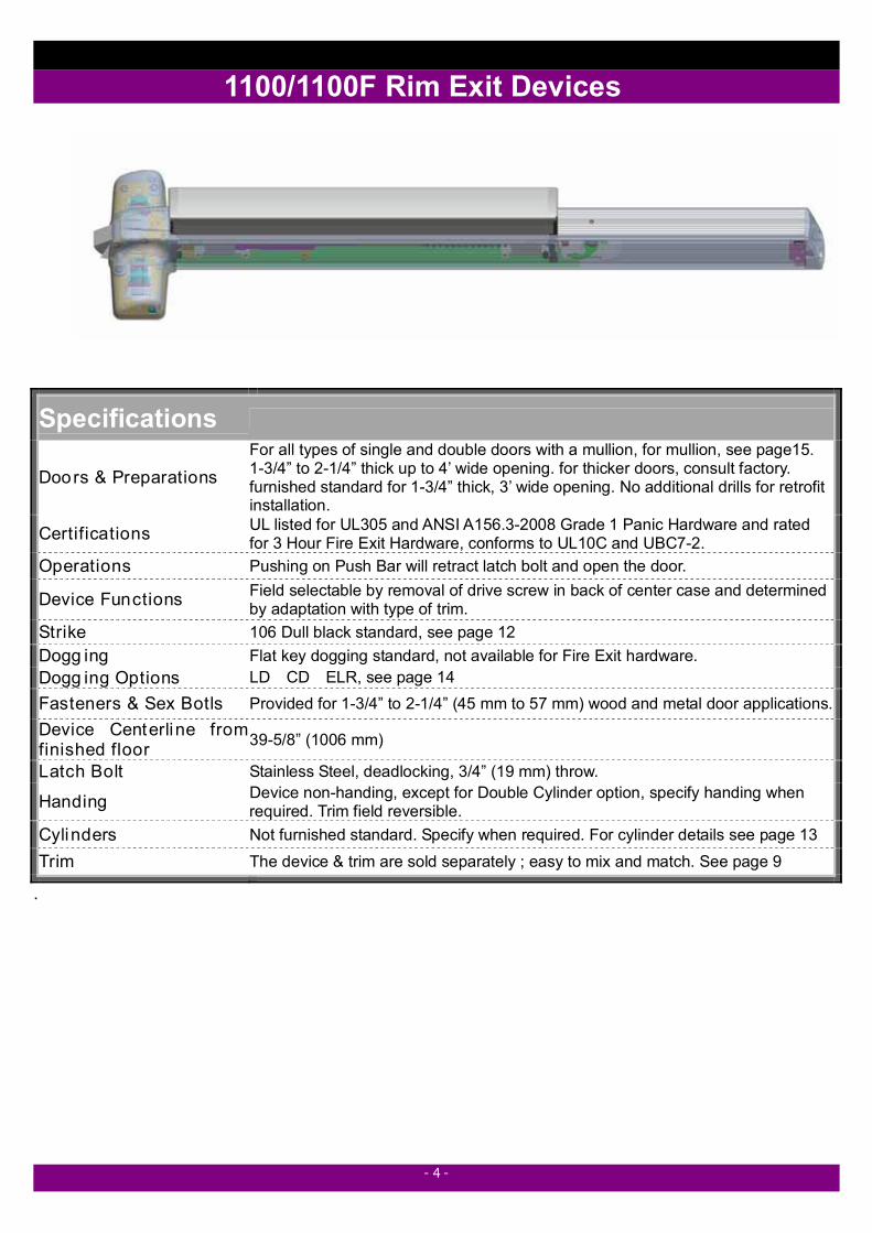
1100/1100F Rim Exit Devices
.
Specifications
Doors & Preparations For all types of single and double doors with a mullion, for mullion, see page15. 1-3/4” to 2-1/4” thick up to 4’ wide opening. for thicker doors, consult factory. furnished standard for 1-3/4” thick, 3’ wide opening. No additional drills for retrofit installation.
Certifications UL listed for UL305 and ANSI A156.3-2008 Grade 1 Panic Hardware and rated for 3 Hour Fire Exit Hardware, conforms to UL10C and UBC7-2.
Operations Pushing on Push Bar will retract latch bolt and open the door.
Device Functions Field selectable by removal of drive screw in back of center case and determined by adaptation with type of trim.
Strike 106 Dull black standard, see page 12 Dogg ing Flat key dogging standard, not available for Fire Exit hardware. Dogg ing Options LD CD ELR, see page 14 Fasteners & Sex Botls Provided for 1-3/4” to 2-1/4” (45 mm to 57 mm) wood and metal door applications. Device Centerline from finished floor 39-5/8” (1006 mm)
Latch Bolt Stainless Steel, deadlocking, 3/4” (19 mm) throw.
Handing Device non-handing, except for Double Cylinder option, specify handing when required. Trim field reversible.
Cylinders Not furnished standard. Specify when required. For cylinder details see page 13
Trim The device & trim are sold separately ; easy to mix and match. See page 9
- 5 -
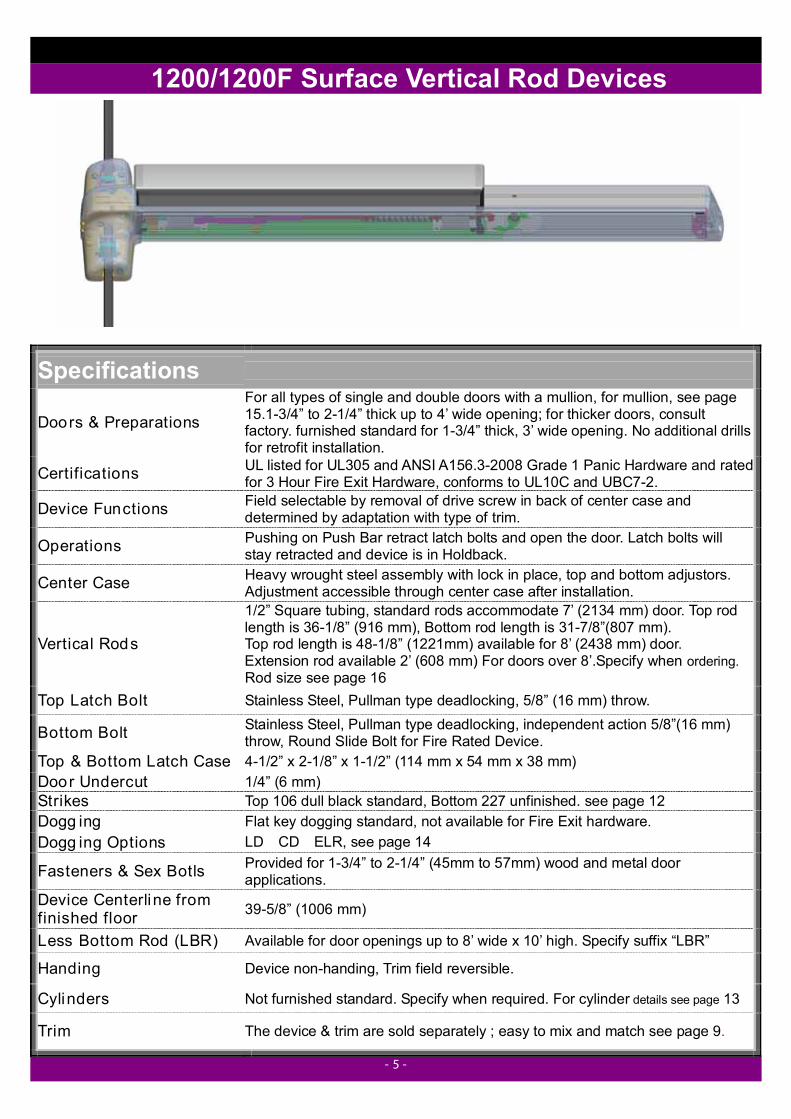
1200/1200F Surface Vertical Rod Devices
Specifications
Doors & Preparations For all types of single and double doors with a mullion, for mullion, see page 15.1-3/4” to 2-1/4” thick up to 4’ wide opening; for thicker doors, consult factory. furnished standard for 1-3/4” thick, 3’ wide opening. No additional drills for retrofit installation.
Certifications UL listed for UL305 and ANSI A156.3-2008 Grade 1 Panic Hardware and rated for 3 Hour Fire Exit Hardware, conforms to UL10C and UBC7-2.
Device Functions Field selectable by removal of drive screw in back of center case and determined by adaptation with type of trim.
Operations Pushing on Push Bar retract latch bolts and open the door. Latch bolts will stay retracted and device is in Holdback.
Center Case Heavy wrought steel assembly with lock in place, top and bottom adjustors. Adjustment accessible through center case after installation.
Vertical Rods
1/2” Square tubing, standard rods accommodate 7’ (2134 mm) door. Top rod length is 36-1/8” (916 mm), Bottom rod length is 31-7/8”(807 mm). Top rod length is 48-1/8” (1221mm) available for 8’ (2438 mm) door. Extension rod available 2’ (608 mm) For doors over 8’.Specify when ordering. Rod size see page 16
Top Latch Bolt Stainless Steel, Pullman type deadlocking, 5/8” (16 mm) throw.
Bottom Bolt Stainless Steel, Pullman type deadlocking, independent action 5/8”(16 mm) throw, Round Slide Bolt for Fire Rated Device.
Top & Bottom Latch Case 4-1/2” x 2-1/8” x 1-1/2” (114 mm x 54 mm x 38 mm) Door Undercut 1/4” (6 mm) Strikes Top 106 dull black standard, Bottom 227 unfinished. see page 12 Dogg ing Flat key dogging standard, not available for Fire Exit hardware. Dogg ing Options LD CD ELR, see page 14
Fasteners & Sex Botls Provided for 1-3/4” to 2-1/4” (45mm to 57mm) wood and metal door applications.
Device Centerline from finished floor 39-5/8” (1006 mm)
Less Bottom Rod (LBR) Available for door openings up to 8’ wide x 10’ high. Specify suffix “LBR”
Handing Device non-handing, Trim field reversible.
Cylinders Not furnished standard. Specify when required. For cylinder details see page 13
Trim The device & trim are sold separately ; easy to mix and match see page 9.
- 6 -
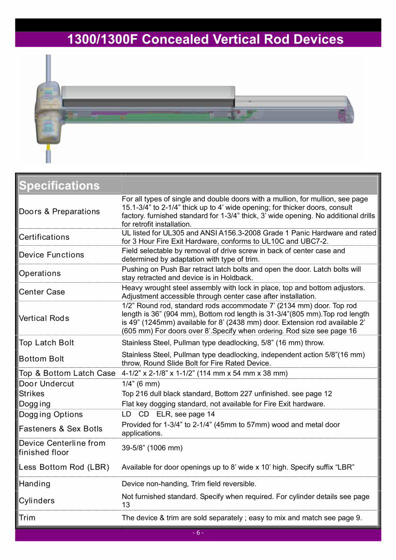
1300/1300F Concealed Vertical Rod Devices
Specifications
Doors & Preparations For all types of single and double doors with a mullion, for mullion, see page 15.1-3/4” to 2-1/4” thick up to 4’ wide opening; for thicker doors, consult factory. furnished standard for 1-3/4” thick, 3’ wide opening. No additional drills for retrofit installation.
Certifications UL listed for UL305 and ANSI A156.3-2008 Grade 1 Panic Hardware and rated for 3 Hour Fire Exit Hardware, conforms to UL10C and UBC7-2.
Device Functions Field selectable by removal of drive screw in back of center case and determined by adaptation with type of trim.
Operations Pushing on Push Bar retract latch bolts and open the door. Latch bolts will stay retracted and device is in Holdback.
Center Case Heavy wrought steel assembly with lock in place, top and bottom adjustors. Adjustment accessible through center case after installation.
Vertical Rods 1/2” Round rod, standard rods accommodate 7’ (2134 mm) door. Top rod length is 36” (904 mm), Bottom rod length is 31-3/4”(805 mm).Top rod length is 49” (1245mm) available for 8’ (2438 mm) door. Extension rod available 2’ (605 mm) For doors over 8’.Specify when ordering. Rod size see page 16
Top Latch Bolt Stainless Steel, Pullman type deadlocking, 5/8” (16 mm) throw.
Bottom Bolt Stainless Steel, Pullman type deadlocking, independent action 5/8”(16 mm) throw, Round Slide Bolt for Fire Rated Device.
Top & Bottom Latch Case 4-1/2” x 2-1/8” x 1-1/2” (114 mm x 54 mm x 38 mm) Door Undercut 1/4” (6 mm) Strikes Top 216 dull black standard, Bottom 227 unfinished. see page 12 Dogg ing Flat key dogging standard, not available for Fire Exit hardware. Dogg ing Options LD CD ELR, see page 14
Fasteners & Sex Botls Provided for 1-3/4” to 2-1/4” (45mm to 57mm) wood and metal door applications.
Device Centerline from finished floor 39-5/8” (1006 mm)
Less Bottom Rod (LBR) Available for door openings up to 8’ wide x 10’ high. Specify suffix “LBR”
Handing Device non-handing, Trim field reversible.
Cylinders Not furnished standard. Specify when required. For cylinder details see page 13
Trim The device & trim are sold separately ; easy to mix and match see page 9.
- 7 -
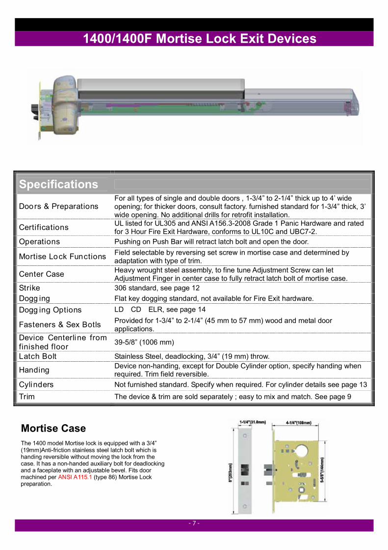
1400/1400F Mortise Lock Exit Devices
Mortise Case
The 1400 model Mortise lock is equipped with a 3/4” (19mm)Anti-friction stainless steel latch bolt which is handing reversible without moving the lock from the case. It has a non-handed auxiliary bolt for deadlocking and a faceplate with an adjustable bevel. Fits door machined per ANSI A115.1 (type 86) Mortise Lock preparation.
Specifications
Doors & Preparations For all types of single and double doors , 1-3/4” to 2-1/4” thick up to 4’ wide opening; for thicker doors, consult factory. furnished standard for 1-3/4” thick, 3’ wide opening. No additional drills for retrofit installation.
Certifications UL listed for UL305 and ANSI A156.3-2008 Grade 1 Panic Hardware and rated for 3 Hour Fire Exit Hardware, conforms to UL10C and UBC7-2.
Operations Pushing on Push Bar will retract latch bolt and open the door.
Mortise Lock Functions Field selectable by reversing set screw in mortise case and determined by adaptation with type of trim.
Center Case Heavy wrought steel assembly, to fine tune Adjustment Screw can let Adjustment Finger in center case to fully retract latch bolt of mortise case.
Strike 306 standard, see page 12 Dogg ing Flat key dogging standard, not available for Fire Exit hardware. Dogg ing Options LD CD ELR, see page 14
Fasteners & Sex Botls Provided for 1-3/4” to 2-1/4” (45 mm to 57 mm) wood and metal door applications.
Device Centerline from finished floor 39-5/8” (1006 mm)
Latch Bolt Stainless Steel, deadlocking, 3/4” (19 mm) throw.
Handing Device non-handing, except for Double Cylinder option, specify handing when required. Trim field reversible.
Cylinders Not furnished standard. Specify when required. For cylinder details see page 13
Trim The device & trim are sold separately ; easy to mix and match. See page 9
- 8 -
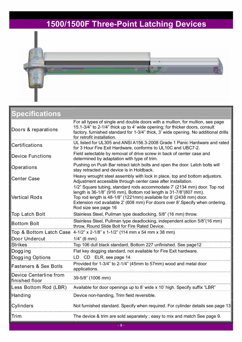
1500/1500F Three-Point Latching Devices
Specifications
Doors & reparations For all types of single and double doors with a mullion, for mullion, see page 15.1-3/4” to 2-1/4” thick up to 4’ wide opening; for thicker doors, consult factory. furnished standard for 1-3/4” thick, 3’ wide opening. No additional drills for retrofit installation.
Certifications UL listed for UL305 and ANSI A156.3-2008 Grade 1 Panic Hardware and rated for 3 Hour Fire Exit Hardware, conforms to UL10C and UBC7-2.
Device Functions Field selectable by removal of drive screw in back of center case and determined by adaptation with type of trim.
Operations Pushing on Push Bar retract latch bolts and open the door. Latch bolts will stay retracted and device is in Holdback.
Center Case Heavy wrought steel assembly with lock in place, top and bottom adjustors. Adjustment accessible through center case after installation.
Vertical Rods
1/2” Square tubing, standard rods accommodate 7’ (2134 mm) door. Top rod length is 36-1/8” (916 mm), Bottom rod length is 31-7/8”(807 mm). Top rod length is 48-1/8” (1221mm) available for 8’ (2438 mm) door. Extension rod available 2’ (608 mm) For doors over 8’.Specify when ordering. Rod size see page 16
Top Latch Bolt Stainless Steel, Pullman type deadlocking, 5/8” (16 mm) throw.
Bottom Bolt Stainless Steel, Pullman type deadlocking, independent action 5/8”(16 mm) throw, Round Slide Bolt for Fire Rated Device.
Top & Bottom Latch Case 4-1/2” x 2-1/8” x 1-1/2” (114 mm x 54 mm x 38 mm) Door Undercut 1/4” (6 mm) Strikes Top 106 dull black standard, Bottom 227 unfinished. See page12 Dogg ing Flat key dogging standard, not available for Fire Exit hardware. Dogg ing Options LD CD ELR, see page 14
Fasteners & Sex Botls Provided for 1-3/4” to 2-1/4” (45mm to 57mm) wood and metal door applications.
Device Centerline from finished floor 39-5/8” (1006 mm)
Less Bottom Rod (LBR) Available for door openings up to 8’ wide x 10’ high. Specify suffix “LBR”
Handing Device non-handing, Trim field reversible.
Cylinders Not furnished standard. Specify when required. For cylinder details see page 13
Trim The device & trim are sold separately ; easy to mix and match See page 9.
- 9 -
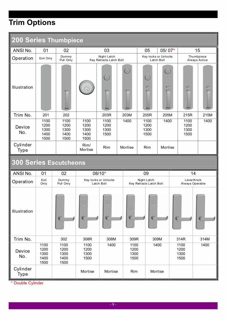
Trim Options
200 Series Thumbpiece ANSI No. 01 02 03 05 05/ 07* 15
Operation Exit Only Dummy Pull Only
Night Latch Key Retracts Latch Bol t
Key locks or Unlocks Latch Bol t
Thumbpiece Always Active
Illustration
Trim No. 201 202 203R 203M 205R 205M 215R 215M
Device No.
1100 1200 1300 1400 1500
1100 1200 1300 1400 1500
1100 1200 1300 1400 1500
1100 1200 1300 1500
1400 1100 1200 1300 1500
1400 1100 1200 1300 1500
1400
Cylinder Type Rim/
Mortise Rim Mortise Rim Mortise
300 Series Escutcheons ANSI No. 01 02 08/10* 09 14
Operation Exit Only
Dummy Pull Only
Key locks or Unlocks Latch Bol t
Night Latch Key Retracts Latch Bol t
Lever/Knob Always Operable
Illustration
Trim No. 302 308R 308M 309R 309M 314R 314M
Device No.
1100 1200 1300 1400 1500
1100 1200 1300 1400 1500
1100 1200 1300 1500
1400 1100 1200 1300 1500
1400 1100 1200 1300 1500
1400
Cylinder Type Mortise Mortise Rim Mortise
* Double Cylinder
- 10 -
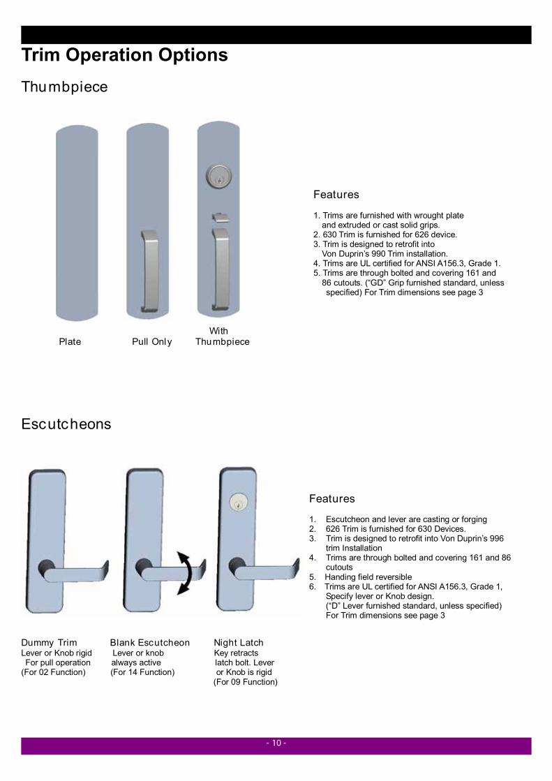
Trim Operation Options Thumbpiece
With Plate Pull Only Thumbpiece
Escutcheons
Dummy Trim Blank Escutcheon Night Latch Lever or Knob rigid Lever or knob Key retracts For pull operation always active latch bolt. Lever (For 02 Function) (For 14 Function) or Knob is rigid (For 09 Function)
Features 1. Trims are furnished with wrought plate and extruded or cast solid grips. 2. 630 Trim is furnished for 626 device. 3. Trim is designed to retrofit into
Von Duprin’s 990 Trim installation. 4. Trims are UL certified for ANSI A156.3, Grade 1. 5. Trims are through bolted and covering 161 and
86 cutouts. (“GD” Grip furnished standard, unless specified) For Trim dimensions see page 3
Features
1. Escutcheon and lever are casting or forging 2. 626 Trim is furnished for 630 Devices. 3. Trim is designed to retrofit into Von Duprin’s 996
trim Installation 4. Trims are through bolted and covering 161 and 86
cutouts 5. Handing field reversible 6. Trims are UL certified for ANSI A156.3, Grade 1,
Specify lever or Knob design. (“D” Lever furnished standard, unless specified) For Trim dimensions see page 3
- 11 -
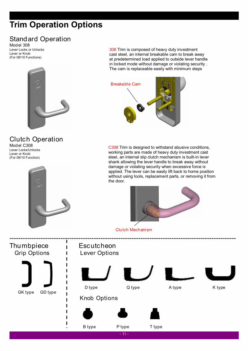
Trim Operation Options Standard Operation Model 308 Lever Locks or Unlocks Lever or Knob (For 08/10 Functions)
Clutch Operation Model C308 Lever Locks/Unlocks Lever or Knob (For 08/10 Function)
------------------------------------------------------------------------------------------------------ Thumbpiece Escutcheon Grip Options Lever Options D type Q type A type K type GK type GD type Knob Options B type P type T type
308 Trim is composed of heavy duty investment cast steel, an internal breakable cam to break away at predetermined load applied to outside lever handle in locked mode without damage or violating security . The cam is replaceable easily with minimum steps
Breakable Cam
C308 Trim is designed to withstand abusive conditions, working parts are made of heavy duty investment cast steel, an internal slip clutch mechanism is built-in lever shank allowing the lever handle to break away without damage or violating security when excessive force is applied. The lever can be easily lift back to home position without using tools, replacement parts, or removing it from the door.
Clu tch Mechanism
- 12 -
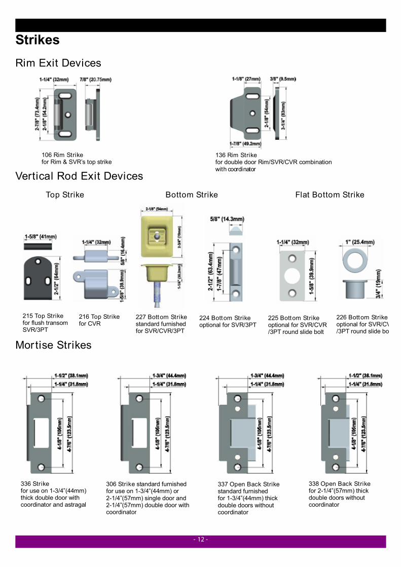
Strikes Rim Exit Devices Vertical Rod Exit Devices Top Strike Bottom Strike Flat Bottom Strike Mor tise Strikes
336 Strike for use on 1-3/4”(44mm) thick double door with coordinator and astragal
306 Strike standard furnished for use on 1-3/4”(44mm) or 2-1/4”(57mm) single door and 2-1/4”(57mm) double door with coordinator
337 Open Back Strike standard furnished for 1-3/4”(44mm) thick double doors without coordinator
338 Open Back Strike for 2-1/4”(57mm) thick double doors without coordinator
225 Bottom Strike optional for SVR/CVR /3PT round slide bolt
226 Bottom Strike optional for SVR/CV/3PT round slide bol
224 Bottom Strike optional for SVR/3PT
227 Bottom Strike standard furnished for SVR/CVR/3PT
216 Top Strike for CVR
215 Top Strike for flush transom SVR/3PT
106 Rim Strike for Rim & SVR’s top strike
136 Rim Strike for double door Rim/SVR/CVR combination with coordinator
- 13 -
Cylinder Options Cylinders are not furnished standard with the device or trim. Schlage C keyway, 6-pin standard, available in 630 or 626 finish. Small Format Interchangeable Core, combinated/uncombinated also available. Specify type and finish when ordering
* must use with cylinder guard Cylinder Cam Cylinder Guard I/C Core
Cylinder Type Functions App lied Trim Appli ed Cylinder
Cyl. Length P/No.
Appli ed Cam
Standard 1-1/4” (441-103) 440-0702 03* / 05* / 07* for Mortise Device 200
I/C 1-3/8" (442-701) 440-0706 Standard 1-1/8” (441-102) 440-0704 08 for RIM/SVR/CVR*/3PT I/C 1-3/8" (442-701) 440-0708 Standard 1-1/8” (441-102) 440-0710 10 for RIM Device I/C 1-3/8" (442-701) 440-0711 Standard 1-5/8” (441-106) 440-0702 08 / 09 / 10 for Mortise Device
300
I/C 1-1/2” (442-702) 440-0706 Standard 1-1/4” (441-103) 440-0702
MORTISE CYLINDER
Cylinder Dogging All Devices I/C 1-3/8” (442-701) 440-0706
03* / 05* for RIM/SVR/CVR/3PT 200
09 for RIM/SVR/CVR/3PT
RIM CYLINDER
10 for RIM/Mortise Device 300
Standard/ I/C
Tailpiece Length 3-1/8” (79.6mm)
Function Number By ANSI A156.3
For use on 03 / 05 / 07 Thumbpiece trim and CVR 08 Escutcheon Trim
Specify 6pin or 7pin ,Combinated or Uncombinated and finish 606 or 626 When ordering
Standard I/C
Standard I/C
For Mortise Device or Cylinder Dogging
For RIM/SVR/CVR/3PT Outside Trim 08 function
Extension Cam for RIM Device Double Cylinder
Cam #440-0702 Cam #440-0704 Cam #440-0710
P/No. 4240-0202
- 14 -
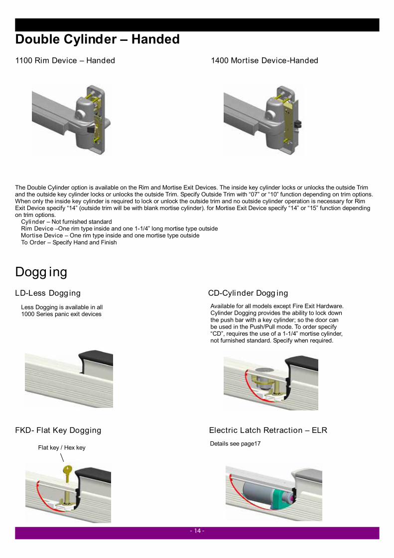
Double Cylinder – Handed 1100 Rim Device – Handed 1400 Mortise Device-Handed The Double Cylinder option is available on the Rim and Mortise Exit Devices. The inside key cylinder locks or unlocks the outside Trim and the outside key cylinder locks or unlocks the outside Trim. Specify Outside Trim with “07” or “10” function depending on trim options. When only the inside key cylinder is required to lock or unlock the outside trim and no outside cylinder operation is necessary for Rim Exit Device specify “14” (outside trim will be with blank mortise cylinder). for Mortise Exit Device specify “14” or “15” function depending on trim options. Cylinder – Not furnished standard Rim Device –One rim type inside and one 1-1/4” long mortise type outside Mortise Device – One rim type inside and one mortise type outside To Order – Specify Hand and Finish
Dogg ing LD-Less Dogg ing CD-Cylinder Dogg ing FKD- Flat Key Dogging Electric Latch Retraction – ELR
Available for all models except Fire Exit Hardware. Cylinder Dogging provides the ability to lock down the push bar with a key cylinder; so the door can be used in the Push/Pull mode. To order specify “CD”, requires the use of a 1-1/4” mortise cylinder, not furnished standard. Specify when required.
Less Dogging is available in all 1000 Series panic exit devices
Flat key / Hex key Details see page17
- 15 -
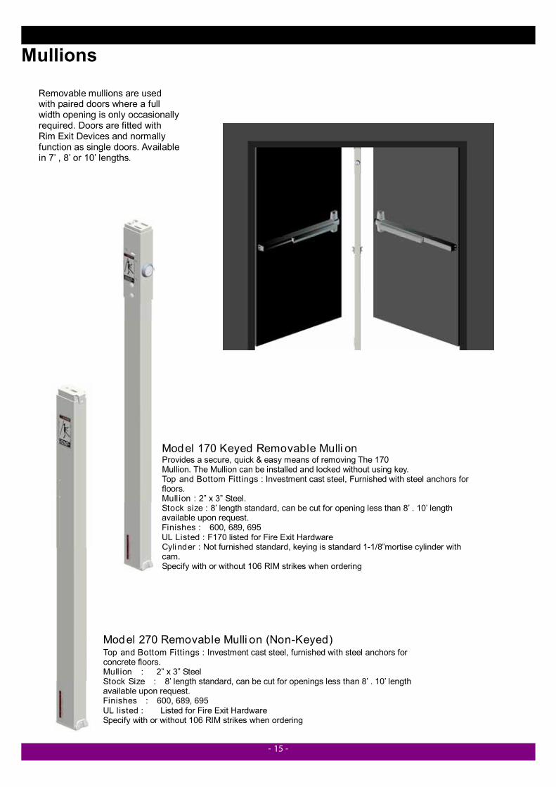
Mullions
Model 270 Removable Mulli on (Non-Keyed) Top and Bottom Fittings : Investment cast steel, furnished with steel anchors for concrete floors. Mull ion : 2” x 3” Steel Stock Size : 8’ length standard, can be cut for openings less than 8’ . 10’ length available upon request. Finishes : 600, 689, 695 UL listed : Listed for Fire Exit Hardware Specify with or without 106 RIM strikes when ordering
Model 170 Keyed Removable Mulli on Provides a secure, quick & easy means of removing The 170 Mullion. The Mullion can be installed and locked without using key. Top and Bottom Fittings : Investment cast steel, Furnished with steel anchors for floors. Mull ion : 2” x 3” Steel. Stock size : 8’ length standard, can be cut for opening less than 8’ . 10’ length available upon request. Finishes : 600, 689, 695 UL Listed : F170 listed for Fire Exit Hardware Cylinder : Not furnished standard, keying is standard 1-1/8”mortise cylinder with cam. Specify with or without 106 RIM strikes when ordering
Removable mullions are used with paired doors where a full width opening is only occasionally required. Doors are fitted with Rim Exit Devices and normally function as single doors. Available in 7’ , 8’ or 10’ lengths.
- 16 -
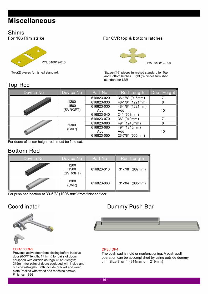
Two(2) pieces furnished standard.
P/N. 616819-010
Sixteen(16) pieces furnished standard for Top and Bottom latches. Eight (8) pieces furnished standard for LBR
P/N. 616819-050
Miscellaneous Shims For 106 Rim strike For CVR top & bottom latches Top Rod
Device No Device No Part No. Rod Length Door Height 616823-020 36-1/8” (916mm) 7’ 616823-030 48-1/8” (1221mm) 8’
1200 1500
(SVR/3PT) 616823-030
Add 616823-040
48-1/8” (1221mm) Add 24” (608mm)
10’
616823-070 36” (940mm) 7’ 616823-080 49” (1245mm) 8’
1300 (CVR) 616823-080
Add 616823-050
49” (1245mm) Add 23-7/8” (605mm)
10’
For doors of lesser height rods must be field cut.
Bottom Rod Device No Device No Part No. Rod Length
1200 1500
(SVR/3PT) 616823-010 31-7/8” (807mm)
1300 (CVR) 616823-060 31-3/4” (805mm)
For push bar location at 39-5/8” (1006 mm) from finished floor .
Coord inator Dummy Push Bar
COR7 / COR9 Prevents active door from closing before inactive door (6-3/4" length; 171mm) for pairs of doors equipped with outside astragal (8-5/8" length; 219mm) for pairs of doors equipped with inside and outside astragals. Both include bracket and wear plate Packed with wood and machine screws Finishes! 626
DP3 / DP4 The push pad is rigid or nonfunctioning. A push /pull operation can be accomplished by using outside dummy trim. Size 3’ or 4’ (914mm or 1219mm)