
Arc Welding solutions from EsAB...Arc Welding solutions from EsAB A full line of arc welding...
87
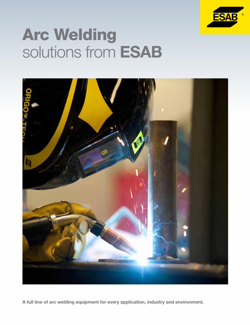
Arc Welding solutions from ESAB A full line of arc welding equipment for every application, industry and environment.
Transcript of Arc Welding solutions from EsAB...Arc Welding solutions from EsAB A full line of arc welding...
Arc Welding solutions from EsAB
A full line of arc welding equipment for every application, industry and environment.
EsAB Welding & Cutting Products / esabna.com / 1.800.EsAB.123
1
Arc Welding Equipment Table of Contents
Process Description .....................................................2
Arc Welding Equipment Selection Guide ...................4
Compacts (power source with built-in wire feeder)
Caddy Mig C200i ............................................................6
Migmaster™ 215 Pro/280 Pro .........................................8
MIG, DC Power Sources, CV/CVCC
Aristo™ Mig U5000i .......................................................10
Origo™ Mig 320/410 ......................................................12
Origo Mig 4002c/6502c ................................................21
Wire Feeders - Semi-Automatic
MobileFeed™ 300AVS .....................................................15
Origo Feed 304 M12 ....................................................16
Origo Feed 304 M13u ..................................................17
Origo Feed 3004 MA23 ................................................19
Origo Feed 3004 MA24 ................................................22
Aristo Feed 3004 U6 .....................................................25
Aristo Feed 3004 U82 Plus ...........................................28
Aristo SuperPulse .........................................................31
Power Supply/Feeder Accessories
Balanced Boom Assembly ...........................................32
Hanging Brackets, Carts, etc. ......................................33
Counterbalance Mini-Boom .........................................34
Mig Welding Guns - Gas-Cooled
MXL - Mig/Mag Gun Consumables ..............................35
Gun Master 250/400 ....................................................36
Mig Welding Guns - Water Cooled
ST-16, ST-21 / ST-21M .................................................38
Mig Welding Guns - Spool Gun / Push-Pull
ST-23A Spool Gun/MT-250SG ................................................40
Mig-PP36 Plus ..............................................................43
Tig/Stick, CC DC/CC AC/DC Power Sources
Origo Arc 410c/650c ....................................................45
MiniArc 161LTS ..............................................................47
CaddyArc 201i ..............................................................48
CaddyTig 2200i ............................................................50
CaddyTig 2200i AC/DC ................................................52
Caddy Selection Guide ................................................54
TXH™ Air/Water Cooled Torches ...................................55
Genuine Heliarc® Tig Torches
Heliarc Tig Torch Selection Guide ................................56
Gas-Cooled Torches
HW-24 ...................................................................57
HW-90 ...................................................................59
HW-9 .....................................................................61
HW-17 ...................................................................63
HW-26 ...................................................................65
Water-Cooled Torches HW-20 ...................................................................67
HW-18 ...................................................................69
HW-25 ...................................................................71
HW-27 ...................................................................73
Collets/Collet Bodies ....................................................75
Cups .............................................................................77
Power Cable Adaptors, Sheaths ..................................79
Heliarc Torch Accessory Kits ........................................79
Back Caps/Insulators ...................................................80
Electrodes ....................................................................80
General Accessories
Remote Controls ..........................................................81
Undercarriages/Truck Kits ............................................83
Twist Lock Cable Connectors ......................................83
Hoses/Fittings ..............................................................83
Ground Clamps, Cable Connectors, Splicers/Lugs,Electrode Holder ....................................84
Description PageDescription Page
Product Catalog ................................................... ARC-23000D

2
Shielded Metal Arc (Stick, Covered Electrode) WeldingIn this first practical arc welding process, the arc is established between a wire rod and the work. The rod is coated with materials which generate a gas and form a slag to protect the weld puddle and the solidifying weld metal from the a osphere. The coating may also supply alloying and refining ingredients, and the slag may help shape the weld bead, especially in vertical and overhead applications.
Electrodes are available for welding most carbon, low alloy and stainless steels, some non-ferrous metals, and a wide range of maintenance and repair applications.
Light-duty work is often done with AC power from low cost transformers; production work usually involves DC power from heavy-duty rectifiers.
Gas Metal Arc (Mig) WeldingThis most flexible metal joining process involves an arc established between the work piece and a wire electrode which is continuously fed by a wire feeder through a torch. The arc continuously melts the electrode to form the weld puddle. An appropriate gas or gas mixture shields the weld area from atmospheric contamination.
The Mig process has the advantages of high deposition rates, speed, excellent weld quality, minimal distortion of the work piece and no stub loss.
Mig welding includes several distinct process variations. Selection depends largely on the work piece thickness and welding position.
Short Circuiting (“Short Arc,” “Dip Transfer”) Involves a small fast-freezing weld puddle. Metal is transferred from the electrode to the puddle by repeated short circuits. Small diameter wires are used and the process operates at low currents and voltages. “Short arc” is used for welding thin gauge metals in all positions and for vertical and overhead welding of heavier sections.
Spray Arc - Electrode metal is transferred to the weld puddle as discrete droplets. Deposition rate is high and there is little or no spatter. With solid wire, the technique is used for 1/8 in. (3.2 mm) and thicker work pieces and for downhand welding.
Pulsed Spray Arc - The welding current is varied rapidly between a high and a low value. Metal is transferred to the work only during the high current period. The high peak current provides excellent arc stability. The period of low current maintains the arc and reduces the average current, making it possible to weld thinner gauge materials and to weld in all positions using larger sized wire electrodes than otherwise possible.
Cored Wire - The electrode is fabricated from strip, enclosing a core of flux and metal which protects and refines the weld puddle and controls bead shape. Some cored wires can be used without external shielding gas. Smaller diameter wires can be used for all position welding. The addition of fluxing, alloy and slag-forming materials often allows high deposition rates, higher welding speeds and improved all-position capability compared with solid wires. This makes cored wire the material of choice in many high-production applications.
Arc Welding Processes
3
Arc Welding Processes
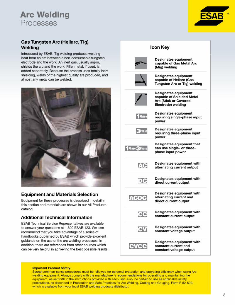
Gas Tungsten Arc (Heliarc, Tig) WeldingIntroduced by ESAB, Tig welding produces welding heat from an arc between a non-consumable tungsten electrode and the work. An inert gas, usually argon, shields the arc and the work. Filler metal, if used, is added separately. Because the process uses totally inert shielding, welds of the highest quality are produced, and almost any metal can be welded.
Equipment and Materials SelectionEquipment for these processes is described in detail in this section and materials are shown in our All Products catalog.
Additional Technical Information ESAB Technical Service Representatives are available to answer your questions at 1.800.ESAB.123. We also recommend that you take advantage of a series of handbooks published by ESAB which provide excellent guidance on the use of the arc welding processes. In addition, there are references from other sources which can be very helpful in achieving the best possible results.
Important Product Safety- Sound common-sense procedures must be followed for personal protection and operating efficiency when using Arc welding equipment. Always comply with the manufacturer’s recommendations for operating and maintaining the equipment, as set forth in the instructions provided with each unit. Also, be certain to use all applicable safety precautions, as described in Precaution and Safe Practices for Arc Welding, Cutting and Gouging, Form F-52-529, which is available from your local ESAB welding products distributor.
Designates equipment capable of Gas Metal Arc (Mig) welding
Icon Key
Designates equipment capable of Heliarc (Gas Tungsten Arc or Tig) welding
Designates equipment capable of Shielded Metal Arc (Stick or Covered Electrode) welding
Designates equipment requiring single-phase input power
Designates equipment requiring three-phase input power
Designates equipment that can use single- or three-phase input power
Designates equipment with alternating current output
Designates equipment with direct current output
Designates equipment with alternating current and direct current output
Designates equipment with constant current output
Designates equipment with constant voltage output
Designates equipment with constant current and constant voltage output

4
Arc Welding Equipment Selection Guide
Mig (GMAW) Tig (GTAW) Stick (SMAW)
Rem
ote
Con
trol,
Volta
ge
Rem
ote
Con
trol,
Cur
rent
Sub
mer
ged
A
rc (S
AW)
Arc
Gou
ge
(AC
AG
)
Sho
rt
arc
Qse
t™
Spr
ay
arc
Flux
co
red
Pul
se
arc
Sup
er
Pul
se
Indu
ctan
ce
Slo
pe
DC
AC
Live
Ti
g
Touc
h Ti
g
Pul
sed
Ti
g
Hi fr
eq.
DC
AC
Arc
Fo
rce
Compact Packages (built-in wire feeder)
Caddy Mig C200i l l l l
Migmaster 215 Pro l l l l
Migmaster 280 Pro l l l l
Migmaster 280 Pro MV l l l l
Power Sources
Origo Mig 320 l l l l
Origo Mig 410 l l l l
Mig 4002c, 4002cw l m l l m t l Opt Opt m l l Opt
Mig 6502c, 6502cw l m l l m t l Opt Opt m l l Opt Opt
Aristo Mig U5000i l m l l m t l m m m l m m l l
Aristo Mig U5000iw l m l l m t l m m m l m m l l
MiniArc 161LTS l l l l
Caddy Arc 201i A33 l l l Auto l
CaddyTig 2200i TA33 l l l l l l
CaddyTig 2200i TA34 l l l(DC) l l l l
Caddy Tig 2200i AC/DC TA34 l l l l l(DC) l l l l l
Origo Arc 410c l l l l l l
Origo Arc 650c l l l l l l
Wire Feeders
MobileFeed 300AVS q l l q
Origo Feed 304 M12 l l l
Origo Feed 304 M13u l l l
Origo Feed 3004 MA23 m m m m m m l Opt
Origo Feed 3004 MA24 m m m m m m m l Opt
Origo Feed 4804 MA24 m m m m m m m l Opt
AristoFeed 3004 U6 m m m m m m m m m m m m m l Opt m
Aristo Feed 4804 U6 m m m m m m m m m m m m m l Opt m
AristoFeed 3004 U82 m m m m m m m m m m m m m l Opt m
AristoFeed 4804 U82 m m m m m m m m m m m m m l Opt m
Legend: l Standard feature best performance, q Limited Applications, t Use add-on pendant,mWhen used on corresponding Aristo or Mig 4002c/5002c/6502c power sources and feeder combination

5
Arc Welding Equipment Selection Guide
NOTES: 1 Rated Output is based on 60 Hz power. Ratings for 50 Hz may be lower. Refer to individual product pages for details. 2Refer to individual product pages for additional details.
Rated Output Primary Input2 Physical
Rated current1 @ duty cycle
Welding current range amps
Max. wire feed speed ipm (m/min)
AC voltage
1 or 3 phase
Net wt. lbs. (kg)
Width in. (cm)
Length in. (cm)
Height in. (cm)
Compact Packages (built-in wire feeder)
Caddy Mig C200i 180A @ 25% 30-200 472 (12) 230 1 26 (12) 7.8 (19.8) 17.7 (44.9) 13.7 (34.7)
Migmaster 215 Pro 250A @ 20% 40-250 748 (19) 208/230 1 220 (100) 16.5 (42) 33.8 (86) 28.7 (73)
Migmaster 280 Pro 250A @ 60% 40-300 750 (19) 208/230 1 341 (155) 21.7 (55) 32 (81) 34.3 (87)
Migmaster 280 Pro MV 250A @ 60% 40-300 750 (19) 230/460/575 1 341 (155) 21.7 (55) 32 (81) 34.3 (87)
Power Sources
Origo Mig 320 320A @ 30% 40-320 230/460 3 245 (111) 16.7 (42.5) 33 (84) 32.7 (83)
Origo Mig 410 400A @ 50% 50-400 230/460 3 320 (145) 21.7 (55.2) 32 (81.2) 36.4 (92.5)
Mig 4002c, 4002cw 400A @ 60% 16-400 230/460 3 328 (149) 25.2 (64) 32.7 (83) 32.9 (83.5)
Mig 6502c, 6502cw 650A @ 60% 16-650 230/460 3 489 (222) 25.2 (64) 32.7 (83) 32.9 (83.5)
Aristo Mig U5000i 500A @ 60% 4-500 460 3 154 (70) 15.5 (39.4) 24.6 (62.5) 19.5 (49.6)
Aristo Mig U5000iw 500A @ 60% 4-500 460 3 198 (90) 15.5 (39.4) 24.6 (62.5) 30.6 (77.6)
MiniArc 161LTS 150A @ 60% 5-150 115/230 1 18 (9) 5.8 (14.6) 15.8 (40.0) 10 (25.5)
CaddyArc 201i A33 220A @ 20% 3-220 230 1 18.3 (8.3) 7.4 (18.8) 16.5 (41.8) 8.2 (20.8)
CaddyTig 2200i TA33 220A @ 20% 3-220 230 1 20.7 (9.4) 7.4 (18.8) 16.5 (41.8) 8.2 (20.8)
CaddyTig 2200i TA34 220A @ 20% 3-220 230 1 20.7 (9.4) 7.4 (18.8) 16.5 (41.8) 8.2 (20.8)
CaddyTig 2200i AC/DC TA 34 220A @ 20% 3-220 230 1 34.6 (15.7) 7.4 (18.8) 16.5 (41.8) 13.6 (34.5)
Origo Arc 410c 400A @ 35% 20-400 230/460 3 346 (157) 31.5 (80) 51.5 (131) 30.7 (78)
Origo Arc 650c 650A @ 35% 20-650 230/460 3 491 (223) 31.5 (80) 51.5 (131) 30.7 (78)
Wire Feeders
MobileFeed 300AVS 400A @ 100% 800 (20.3) n/a 32 (14.5) 8.6 (21.7) 20.7 (52.6) 17.2 (43.7)
Origo Feed 304 M12 630A @ 60% 1000 (25) 42 1 33.1 (15) 10.8 (27.5) 27.2 (69) 15.5 (42)
Origo Feed 304 M13u 630A @ 60% 1000 (25) 42 1 33 (15) 10.8 (27.5) 27.2 (69) 16.1 (42)
Origo Feed 3004 MA23 630A @ 60% 1000 (25) 42 1 33.1 (15) 10.8 (27.5) 27.2 (69) 15.5 (42)
Origo Feed 3004 MA24 630A @ 60% 1000 (25) 42 1 33.1 (15) 10.8 (27.5) 27.2 (69) 15.5 (42)
Origo Feed 4804 MA24 630A @ 60% 1000 (25) 42 1 33.1 (15) 10.8 (27.5) 27.2 (69) 15.5 (42)
Aristo Feed 3004 U6 630A @ 60% 1000 (25) 42 1 33.1 (15) 10.8 (27.5) 27.2 (69) 15.5 (42)
Aristo Feed 4804 U6 630A @ 60% 1000 (25) 42 1 33.1 (15) 10.8 (27.5) 27.2 (69) 15.5 (42)
Aristo Feed 3004 U82 630A @ 60% 1000 (25) 42 1 33.1 (15) 10.8 (27.5) 27.2 (69) 15.5 (42)
Aristo Feed 4804 U82 630A @ 60% 1000 (25) 42 1 33.1 (15) 10.8 (27.5) 27.2 (69) 15.5 (42)

6
Co
mp
acts
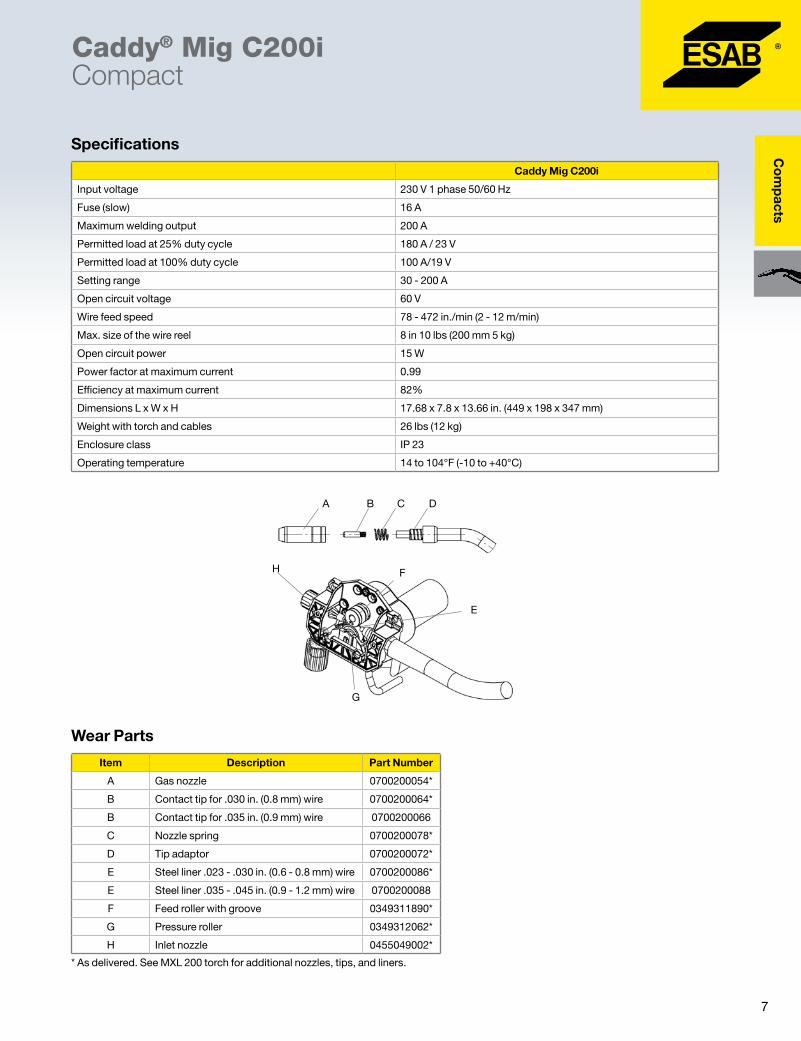
Caddy® Mig C200iCompact
� Can weld mild steel, aluminum, stainless steel as well as MIG/MAG brazing
� QSet - automatically selects correct parameters for required wire/gas combination
� Its light weight and portability make it easy to get to the job site, indoors or outdoors
� Has PFC (power factor correction) ensures stable welding power, even when operated from a portable generator
� Polarity change - allows you to use gasless cored wire
� Ergonomic, high quality MXL180 torch 10 ft. (3 m) long
� Optimized for .030 in. wire. Will also accept .023 in. and 0.35 in. wires as needed
The Caddy Mig C200i is an easy-to-use, intelligent and powerful machine for MIG/MAG welding mild steels, aluminum and stainless steel as well as MIG brazing. The unit is also extremely portable, making the Caddy Mig C200i an excellent choice for repair, maintenance, and assembly work – both in the workshop and while on the go.
Made from advanced materials, the Caddy Mig C200i’s housing is lightweight, durable, and impact-resistant. The machine also includes a built-in cable for easy transportation. Weighing a little over 26 lbs. (12 kg), the Caddy Mig C200i is the lightest welding unit in its output class. But what really sets the Caddy Mig C200i apart is its performance. The PFC (power factor correction) feature provides 30% more welding power from the same sized fuse.
To make sure operation is a breeze, the Caddy Mig C200i is equipped with QSet™. With QSet, you only need to set the plate thickness, not only will QSet automatically set all of the welding parameters, it also automatically adjusts during the process to maintain the optimum wire/ gas combination and prevent waste of resources. If you prefer, you can make adjustments with the wire feed speed and voltage.
A single-phase input connection makes it easy to find an electrical source. And the machine performs equally as well when powered by a portable generator. The Caddy Mig C200i is an efficient inverter power source.
Inside the Caddy Mig C200i’s side panel is a wire feeder that fits a wire spool with an inner diameter of 2 in. (51 mm), an external diameter of 8 in. (200 mm), and a width of 2.125 in. (55 mm).
The Caddy Mig C200i is optimized to perform for welding with .023, .030 and .035 in. solid or cored wires. We recommend the following ESAB wires when welding with the Caddy Mig C2001. Spoolarc® 86, .023, .030 and .035 in. for welding of mild steels. Coreshield 15, .030 in. for gasless welding of mild steels. ERCuSi-A .030 and .035 in. for MIG /MAG brazing. ESAB ER308LSi MIG .023, .030 and .035 in. for 18Cr 8Ni stainless steel welding. Alcotec 5183 .035 in. for aluminum welding.
Instruction Manual ....................................................0440001031Product Data Page ................................................... ARC-23287
Ordering informationCaddy Mig C200i, 1 ph 230V ...................................0558101321Ready to Weld package includes: 10 ft. (3 m) MXL 180 torch, R-33 FM580 regulator/flowmeter, 10 ft. (3 m) mains cable with 6-50P plug. 14.5 ft. (4.5 m) gas hose with ‘B’ male connector, 10 ft. (3 m) return cable with clamp, simple shoulder strap, fitted wear parts in torch/feeder (for .030 in. wire) and instruction manual. We also include 11 lbs. of 70S-6 mild steel .030” in. wire so you can begin welding immediately.
AccessoriesTrolley ....................................................................... 0459366887Includes gas shelf.
7
Co
mp
acts
Caddy® Mig C200iCompact
Specifications
F
E
G
H
Wear Parts
A B C D
Caddy Mig C200i
Input voltage 230 V 1 phase 50/60 Hz
Fuse (slow) 16 A
Maximum welding output 200 A
Permitted load at 25% duty cycle 180 A / 23 V
Permitted load at 100% duty cycle 100 A/19 V
Setting range 30 - 200 A
Open circuit voltage 60 V
Wire feed speed 78 - 472 in./min (2 - 12 m/min)
Max. size of the wire reel 8 in 10 lbs (200 mm 5 kg)
Open circuit power 15 W
Power factor at maximum current 0.99
Efficiency at maximum current 82%
Dimensions L x W x H 17.68 x 7.8 x 13.66 in. (449 x 198 x 347 mm)
Weight with torch and cables 26 lbs (12 kg)
Enclosure class IP 23
Operating temperature 14 to 104°F (-10 to +40°C)
Item Description Part Number
A Gas nozzle 0700200054*
B Contact tip for .030 in. (0.8 mm) wire 0700200064*
B Contact tip for .035 in. (0.9 mm) wire 0700200066
C Nozzle spring 0700200078*
D Tip adaptor 0700200072*
E Steel liner .023 - .030 in. (0.6 - 0.8 mm) wire 0700200086*
E Steel liner .035 - .045 in. (0.9 - 1.2 mm) wire 0700200088
F Feed roller with groove 0349311890*
G Pressure roller 0349312062*
H Inlet nozzle 0455049002*
* As delivered. See MXL 200 torch for additional nozzles, tips, and liners.

8
Co
mp
acts
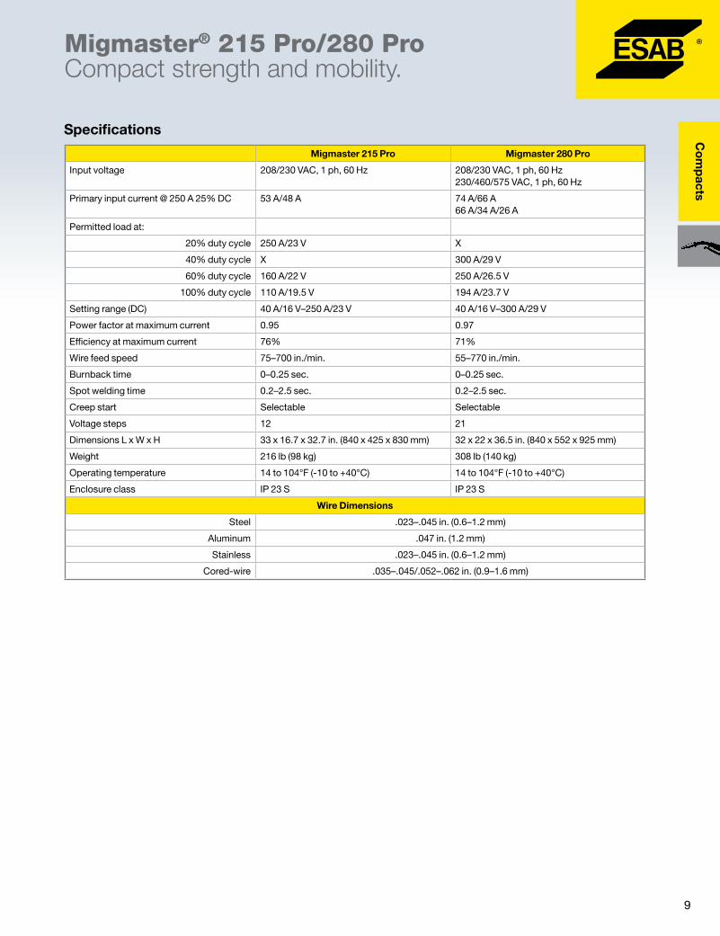
Migmaster® 215 Pro/280 ProCompact strength and mobility.
� Equipped with V/A digital meter with hold feature
� Creep start – gradual feed of wire for ultimate starts
� Adjustable wire feed speed
� Adjustable burnback timer – gives correct stick-out
� Spot welding timer
� Outstanding welding characteristics – efficient, high-quality welding
�Wide current and voltage range – multi-purpose applications
� Spool gun on-demand
� Sturdy, galvanized metal casing with air filter (optional)
The Migmaster 215 Pro/280 Pro are sturdy and robust step-controlled welding power units. They are intended for medium (215 Pro) to heavy-duty (280 Pro) MIG/MAG welding with solid wires of steel, stainless steel, or aluminum, as well as cored-wires with or without shielding gas. ESAB’s proven technology and software provide reliability and outstanding welding performance.
The units are made with a strong galvanized metal casing to withstand harsh environments. Large wheels and built-in wire feeder ensure these machines are practical and mobile solutions. The units are fan-cooled and equipped with thermal overload protection.
A wide current and voltage range, plus two inductance outlets (280 Pro) make it easy to optimize settings for a variety of filler materials and gases. Migmaster 215 Pro/280 Pro units are equipped with the potentiometers to set the wire feed speed, spot welding time, and burnback time adjustment. Furthermore, Migmaster machines are equipped with such functions as creep start and inching.
OrderingInformationMigmaster 215 Pro Package 208/230 V, 15 ft. torch .......................................... 0558101322Migmaster 280 Pro Package 208/230 V, 15 ft. torch .......................................... 0558101324 230/460/575 V, 15 ft. torch ................................... 0558101365Ready to Weld package includes: console with wheel kit installed, 15 ft. (4.5 m) Gunmaster 250 A torch, 10 ft. (3 m) power cord, 10 ft. (3 m) work cable, R-33 FM580 regulator/flowmeter, (1) .035 and .045 contact tip, and 10# spool of 87HP .035
AccessoriesAir filter 215 Pro .................................................................... 0349302599 280 Pro .................................................................... 0349312810Cable and torch holder 215 Pro .................................................................... 0349303362 280 Pro .................................................................... 0349312800MT-250SG spool gun ...........................................................36779ST-23A spool gun (requires 37301 adapter) ......................19164Dual Cylinder Tray Kit 215 Pro (208/230v) ................................................. 0349309312 280 Pro ................................................................... 0349312760Feed Rolls .023 – .030 in. V-HARD ........................................... 0367556001 .030 – .040 in. V-HARD ........................................... 0367556002 .035 – .045 in. V-HARD* .......................................... 0349312497 .040 – 3/64 in. U-SOFT ........................................... 0367556004 .045 in./.052 – .062 in. VK-G .................................. 0367556006* Note: Included in ready to weld package
Instruction Manual ..................................................... 0349301164Product Data Page ..................................................... ARC-23281
9
Co
mp
acts
Migmaster® 215 Pro/280 ProCompact strength and mobility.
Specifications
Migmaster 215 Pro Migmaster 280 Pro
Input voltage 208/230 VAC, 1 ph, 60 Hz 208/230 VAC, 1 ph, 60 Hz 230/460/575 VAC, 1 ph, 60 Hz
Primary input current @ 250 A 25% DC 53 A/48 A 74 A/66 A 66 A/34 A/26 A
Permitted load at:
20% duty cycle 250 A/23 V X
40% duty cycle X 300 A/29 V
60% duty cycle 160 A/22 V 250 A/26.5 V
100% duty cycle 110 A/19.5 V 194 A/23.7 V
Setting range (DC) 40 A/16 V–250 A/23 V 40 A/16 V–300 A/29 V
Power factor at maximum current 0.95 0.97
Efficiency at maximum current 76% 71%
Wire feed speed 75–700 in./min. 55–770 in./min.
Burnback time 0–0.25 sec. 0–0.25 sec.
Spot welding time 0.2–2.5 sec. 0.2–2.5 sec.
Creep start Selectable Selectable
Voltage steps 12 21
Dimensions L x W x H 33 x 16.7 x 32.7 in. (840 x 425 x 830 mm) 32 x 22 x 36.5 in. (840 x 552 x 925 mm)
Weight 216 lb (98 kg) 308 lb (140 kg)
Operating temperature 14 to 104°F (-10 to +40°C) 14 to 104°F (-10 to +40°C)
Enclosure class IP 23 S IP 23 S
Wire Dimensions
Steel .023–.045 in. (0.6–1.2 mm)
Aluminum .047 in. (1.2 mm)
Stainless .023–.045 in. (0.6–1.2 mm)
Cored-wire .035–.045/.052–.062 in. (0.9–1.6 mm)
10
DC
- C
V /
CV
CC
Po
wer
So
urce
s
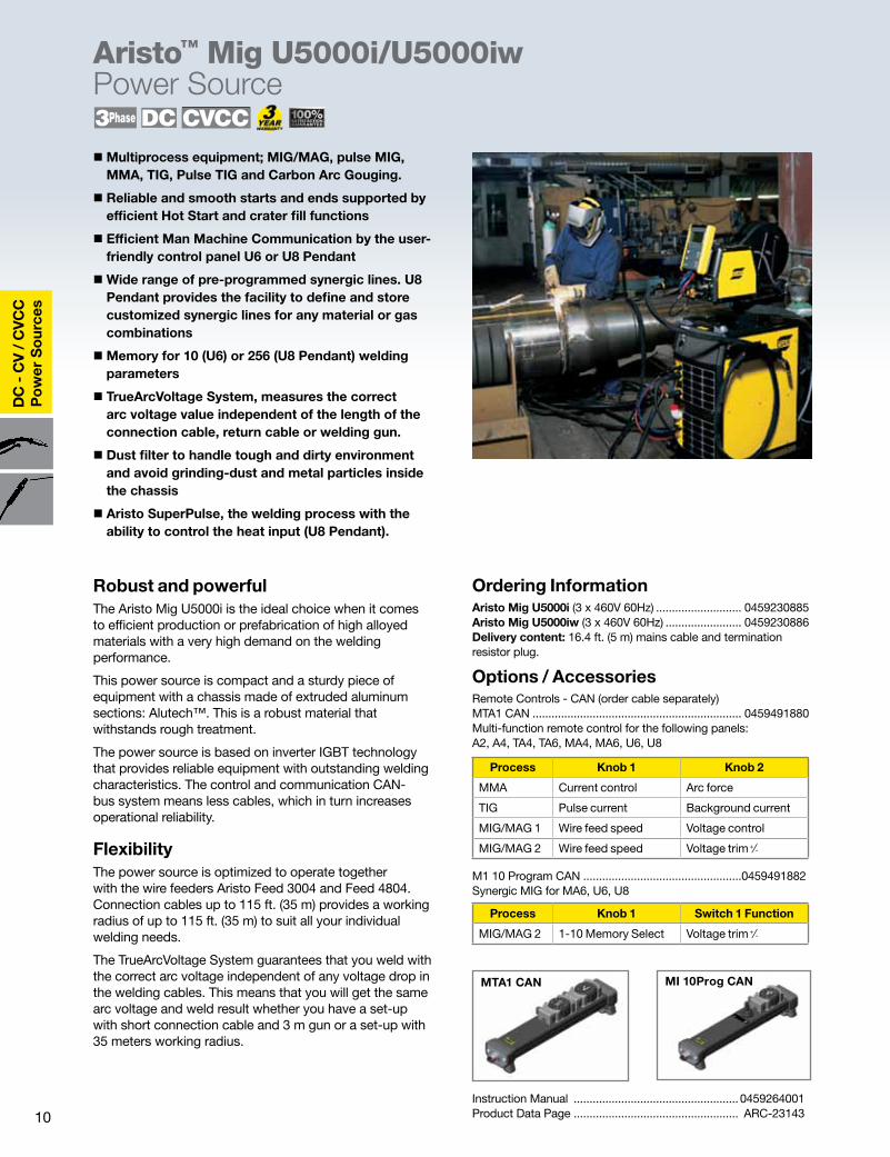
Robust and powerfulThe Aristo Mig U5000i is the ideal choice when it comes to efficient production or prefabrication of high alloyed materials with a very high demand on the welding performance.
This power source is compact and a sturdy piece of equipment with a chassis made of extruded aluminum sections: Alutech™. This is a robust material that withstands rough treatment.
The power source is based on inverter IGBT technology that provides reliable equipment with outstanding welding characteristics. The control and communication CAN-bus system means less cables, which in turn increases operational reliability.
Flexibility The power source is optimized to operate together with the wire feeders Aristo Feed 3004 and Feed 4804. Connection cables up to 115 ft. (35 m) provides a working radius of up to 115 ft. (35 m) to suit all your individual welding needs.
The TrueArcVoltage System guarantees that you weld with the correct arc voltage independent of any voltage drop in the welding cables. This means that you will get the same arc voltage and weld result whether you have a set-up with short connection cable and 3 m gun or a set-up with 35 meters working radius.
�Multiprocess equipment; MIG/MAG, pulse MIG, MMA, TIG, Pulse TIG and Carbon Arc Gouging.
� Reliable and smooth starts and ends supported by efficient Hot Start and crater fill functions
� Efficient Man Machine Communication by the user-friendly control panel U6 or U8 Pendant
�Wide range of pre-programmed synergic lines. U8 Pendant provides the facility to define and store customized synergic lines for any material or gas combinations
�Memory for 10 (U6) or 256 (U8 Pendant) welding parameters
� TrueArcVoltage System, measures the correct arc voltage value independent of the length of the connection cable, return cable or welding gun.
� Dust filter to handle tough and dirty environment and avoid grinding-dust and metal particles inside the chassis
� Aristo SuperPulse, the welding process with the ability to control the heat input (U8 Pendant).
Instruction Manual .................................................... 0459264001Product Data Page .................................................... ARC-23143
Aristo™ Mig U5000i/U5000iwPower Source
Ordering InformationAristo Mig U5000i (3 x 460V 60Hz) ........................... 0459230885Aristo Mig U5000iw (3 x 460V 60Hz) ........................ 0459230886Delivery content: 16.4 ft. (5 m) mains cable and termination resistor plug.
Options / AccessoriesRemote Controls - CAN (order cable separately)MTA1 CAN .................................................................. 0459491880Multi-function remote control for the following panels: A2, A4, TA4, TA6, MA4, MA6, U6, U8
M1 10 Program CAN ..................................................0459491882Synergic MIG for MA6, U6, U8
MTA1 CAN MI 10Prog CAN
Process Knob 1 Knob 2
MMA Current control Arc force
TIG Pulse current Background current
MIG/MAG 1 Wire feed speed Voltage control
MIG/MAG 2 Wire feed speed Voltage trim +⁄-
Process Knob 1 Switch 1 Function
MIG/MAG 2 1-10 Memory Select Voltage trim +⁄-

11
DC
- CV
/ CV
CC
Po
wer S
ources
Handle includes mounting screws for separate installation. (Complete set = 2) ...................................0459307881Trolley 1 (Standard) ....................................................0458530880Trolley 2 (with Mini Boom or Dual Feeder) .................0458603880Guide Pin (If no trolley) ...............................................0458731880Quick Connector Kit for current, water and shielding gas supply for 2x AristoFeed .....................0459546880MMC kit for MMC panel mounted in the power source ..........................................................0459579880 MMC - U6 ...............................................................0458535890Connection cables, water cooled torches 5.6 ft. (1.7 m) ...........................................................0459528970 16.4 ft. (5.0 m) .........................................................0459528971 32.8 ft. (10.0 m) .......................................................0459528972 49.2 ft. (15.0 m) .......................................................0459528973 82.0 ft. (25.0 m) .......................................................0459528974 115 ft. (35.0 m) ........................................................0459528975ESAT service kit ........................................................0458847881
Aristo™ Mig U5000i/U5000iwPower Source
Specifications
Remote Control Cables - CANOptions/Accessories
Aristo Mig U5000i
Input Voltage 460 V, 3 phase, 60 Hz
Fuse slow, A 35
Setting range
MIG/MAG, A/V 16-500/8-60
MMA DC, A 16-500
TIG DC, A 4-500
Permitted load:
60% duty cycle, A/V 500/39
100% duty cycle, A/V 400/34
Open circuit voltage, V 68-88
Energy save mode, W 50
Input power, kW 23
Power factor at maximum current 0.85
Efficiency at maximum current, % 86
Control voltage, V, Hz 42, 50/60
Dimensions L x W x H 25 in. x 16 in. x 20 in. (625 x 394 x496 mm)
Dimensions with cooling unit 25 in. x 16 in. x 31 in. (625 x 394x 776 mm)
Enclosure class IP 23
Insulation class (main trafo.) H
Operating temperature, °C -10 till +40
Weight 152 lbs. (69 kg)
Application class S
Standards IEC/EN 60974-1, EN 50199
Water cooling unit
Cooling capacity, W, l/min 2500 at 40°C, .4 (1.5)
Coolant volume, l/min 1.4 (5.5)
Max flow, l/min .5 (2.0)
Max pressure, bar 50 (3.4)
Weight 44.1 lbs (20 kg)
Dimension L x W x H 25 in. x 16 in. x 11 in. (621 x 389 x 266 mm)
Length CAN 12 Pin CAN 10 Pin
.25 m 0459554884 0459960883
5 m 0459554880 0459960880
10 m 0459554881 0459960881
15 m 0459554882 - NA -
25 m 0459554883 0459960882
5 m HD 0459554880 0459960880
10 m HD - NA - 0459960881
25 m HD - NA - 0459960882

12
DC
- C
V /
CV
CC
Po
wer
So
urce
s
Origo™ Mig 320/410with Origo Feed 304 M12
�WFS range 31-1000 ipm
� 2/4 stroke – simplifies welding
� Adjustable burn-back timer – gives correct stick-out
� Creep start – gradual feed of wire for ultimate starts
� Quick connectors – shortest possible setup times
�Multiple mounting options – counterbalance and mast, wheel kit, or hanging bracket
� Inching/gas purge (optional)
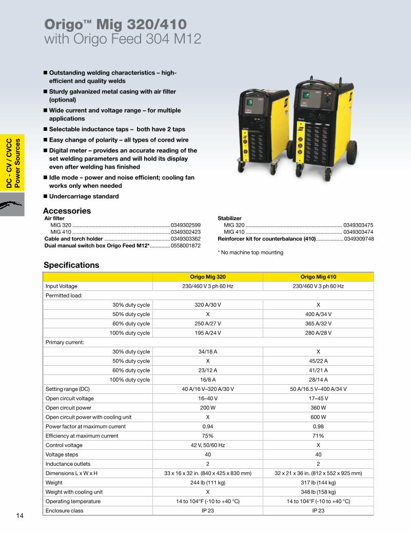
Powerful and flexible.The Origo MIG 320/410 are step-switched power sources for medium (320) to heavy-duty (410) MIG/MAG welding. The machines are made with a strong galvanized metal casing to withstand harsh environments. Its large wheels, sturdy lifting eyelets, and an undercarriage designed for forklift transport make the Origo MIG machine easy to move. The wide current and voltage make it easy to optimize settings for a wide variety of filler metals and gases.
The machines are optimized to operate together with the Origo Feed 304 M12 wire feeder. Electronically controlled feeding gives an accurate and stable arc. The feeders are available with 1.8 in. diameter (30 mm) feed rollers for wires up to .062 in. diameter (1.6 mm).
The wire feed unit sits on a swivel post mounted on the top of the Origo MIG 320/410, providing a 360-degree radius of operation. The feeder mechanism is easy to access, and all wear parts can easily be exchanged. A single pressure device makes it easy to adjust the appropriate feeding pressure. All electronic components are protected in a separate compartment.
Ordering InformationReady to Weld Packages MIG 320 Origo Feed 304 M12 ................................0558101326 MIG 410 Origo Feed 304 M12 ................................0558101328Basic Packages MIG 320 Origo Feed 304 M12 ................................0558101327 MIG 410 Origo Feed 304 M12 ................................0558101329
Ready to Weld package includes: power source, feeder, 15 ft. (4.5 m) 400 A torch, 5.5 ft. (1.7 m) connection cable set, 16.4 ft. (5 m) work cable, reg. flowmeter Ar CO2.Basic package includes: power source, feeder, 15 ft. (4.5 m) 400 A torch.
Instruction Manual Origo Mig 320 ........................................................ 0349301158 Origo Mig 410 ........................................................ 0349301159 Feed 304 M12 ........................................................ 0459161187Product Data Page ..................................................... ARC-23283
Feeder AccessoriesWheel kit ...................................................................0458707880Strain relief for welding torch .................................0457341881Strain relief for connection cables .........................0459234880Lifting eye ..................................................................0458706880Quick connector Marathon Pac™ ........................ F102440880Adapter for 11 lb spool ............................................0455410001Steel spool cover .....................................................0459431880Counter-balance Mini boom For 12" spools ........................................................0458705880 For 18" spools ........................................................0458705882Extension bracket for 60 lb coil ..............................0459233880Coil adapter ........................................................................34323Inching and gas purge kit .......................................0459465880
Connection Cable Sets Air-Cooled Torch, 23 Pole 5.5 ft. (1.7 m) ...........................................................0349312470 16.4 ft. (5.0 m) ........................................................0349312471 32.8 ft. (10.0 m) ......................................................0349312472 49.2 ft. (15.0 m) .......................................................0349312473 82.0 ft. (25.0 m) ......................................................0349312474 114.8 ft. (35.0 m) .....................................................0349312475Includes: control cable, electrode cable, and gas hose.
TorchesGun Master 400cc 25 ft. (7.6 m) Basic ..................................................0558001674 12 ft. (3.6 m) x .035–.045 in. ...................................0558001667 15 ft. (4.5 m) x .035–.045 in. ...................................0558001669 15 ft. (4.5 m) x .052–1/16 in. ...................................0558001670See ARC-23095 for additional information.
13
DC
- CV
/ CV
CC
Po
wer S
ources
Origo™ Mig 320/410with Origo Feed 304 M12
* Requires optional accessories
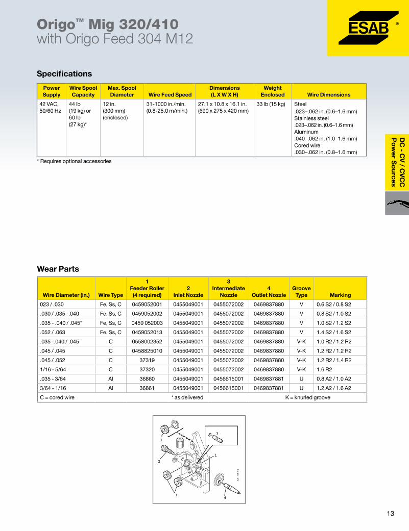
Specifications
Wear Parts
Power Supply
Wire Spool Capacity
Max. Spool Diameter Wire Feed Speed
Dimensions (L X W X H)
Weight Enclosed Wire Dimensions
42 VAC, 50/60 Hz
44 lb (19 kg) or 60 lb (27 kg)*
12 in. (300 mm) (enclosed)
31-1000 in./min. (0.8-25.0 m/min.)
27.1 x 10.8 x 16.1 in. (690 x 275 x 420 mm)
33 lb (15 kg) Steel .023–.062 in. (0.6–1.6 mm) Stainless steel .023–.062 in. (0.6–1.6 mm) Aluminum .040–.062 in. (1.0–1.6 mm) Cored wire .030–.062 in. (0.8–1.6 mm)
Wire Diameter (in.) Wire Type
1 Feeder Roller (4 required)
2 Inlet Nozzle
3 Intermediate
Nozzle4
Outlet NozzleGroove
Type Marking
023 / .030 Fe, Ss, C 0459052001 0455049001 0455072002 0469837880 V 0.6 S2 / 0.8 S2
.030 / .035 -.040 Fe, Ss, C 0459052002 0455049001 0455072002 0469837880 V 0.8 S2 / 1.0 S2
.035 - .040 / .045* Fe, Ss, C 0459 052003 0455049001 0455072002 0469837880 V 1.0 S2 / 1.2 S2
.052 / .063 Fe, Ss, C 0459052013 0455049001 0455072002 0469837880 V 1.4 S2 / 1.6 S2
.035 -.040 / .045 C 0558002352 0455049001 0455072002 0469837880 V-K 1.0 R2 / 1.2 R2
.045 / .045 C 0458825010 0455049001 0455072002 0469837880 V-K 1.2 R2 / 1.2 R2
.045 / .052 C 37319 0455049001 0455072002 0469837880 V-K 1.2 R2 / 1.4 R2
1/16 - 5/64 C 37320 0455049001 0455072002 0469837880 V-K 1.6 R2
.035 - 3/64 Al 36860 0455049001 0456615001 0469837881 U 0.8 A2 / 1.0 A2
3/64 - 1/16 Al 36861 0455049001 0456615001 0469837881 U 1.2 A2 / 1.6 A2
C = cored wire * as delivered K = knurled groove
14
DC
- C
V /
CV
CC
Po
wer
So
urce
s
� Outstanding welding characteristics – high-efficient and quality welds
� Sturdy galvanized metal casing with air filter (optional)
�Wide current and voltage range – for multiple applications
� Selectable inductance taps – both have 2 taps
� Easy change of polarity – all types of cored wire
� Digital meter – provides an accurate reading of the set welding parameters and will hold its display even after welding has finished
� Idle mode – power and noise efficient; cooling fan works only when needed
� Undercarriage standard
Origo™ Mig 320/410with Origo Feed 304 M12
Air filter MIG 320 ...................................................................0349302599 MIG 410 ...................................................................0349302423Cable and torch holder .............................................0349303362Dual manual switch box Origo Feed M12* ..............0558001872
Stabilizer MIG 320 .................................................................. 0349303475 MIG 410 .................................................................. 0349303474Reinforcer kit for counterbalance (410) ...................0349309748
* No machine top mounting
Specifications
Accessories
Origo Mig 320 Origo Mig 410
Input Voltage 230/460 V 3 ph 60 Hz 230/460 V 3 ph 60 Hz
Permitted load:
30% duty cycle 320 A/30 V X
50% duty cycle X 400 A/34 V
60% duty cycle 250 A/27 V 365 A/32 V
100% duty cycle 195 A/24 V 280 A/28 V
Primary current:
30% duty cycle 34/18 A X
50% duty cycle X 45/22 A
60% duty cycle 23/12 A 41/21 A
100% duty cycle 16/8 A 28/14 A
Setting range (DC) 40 A/16 V–320 A/30 V 50 A/16.5 V–400 A/34 V
Open circuit voltage 16–40 V 17–45 V
Open circuit power 200 W 360 W
Open circuit power with cooling unit X 600 W
Power factor at maximum current 0.94 0.98
Efficiency at maximum current 75% 71%
Control voltage 42 V, 50/60 Hz X
Voltage steps 40 40
Inductance outlets 2 2
Dimensions L x W x H 33 x 16 x 32 in. (840 x 425 x 830 mm) 32 x 21 x 36 in. (812 x 552 x 925 mm)
Weight 244 lb (111 kg) 317 lb (144 kg)
Weight with cooling unit X 348 lb (158 kg)
Operating temperature 14 to 104°F (-10 to +40 °C) 14 to 104°F (-10 to +40 °C)
Enclosure class IP 23 IP 23

15
Wire
Feeders
Ordering InformationEach MobileFeed wire feeder includes gas solenoid, contactor, and dual groove feed rolls.MobileFeed 300AVS LC40 ........................................0558005729Note: Uses LC40 type cable connector
Accessories50mm OKC Cable Connectors OKC Female Cable Connector, 1/0-4/0 cable ........... 13735631 OKC Male Cable Connector, 1/0-4/0 cable ............... 13732513LC40 Cable Connectors LC40 Cable Connector Set (male / female), 1/0-3/0........ 81F25 LC40 Male Cable Connector, 1/0-3/0 .............................. 81F26 LC40 Female Cable Connector, 1/0-3/0 .......................... 81F27
� Arc voltage feeder for use with DC, CC or CV power supplies with straight (DC-) or reverse (DC+) polarity operation - no switches to set
� Ideal for harsh environments such as pipe lines, shipyards, offshore, general fabrication and more
� For use with 8 or 12 in. wire spools for enhanced portability, smaller size and reduced weight
� Enclosed, super impact-resistant case protects against dirt, metal grit, and moisture as well as extreme abuse, from grinding sparks, corrosive chemicals, drops and more
� 'CC' Euro torch connection for fast setup - no external gas hose or trigger wire
� Heavy duty 4 roll feed unit with PWM drive provides powerful, dependable wire feeding with Automatic slow wire run-in and Electronic Dynamic Braking for overall improved operation
� Safety features include insulated case, secondary contactor, low voltage torch trigger circuit and overload protection
� Designed to meet the most rigid standards. Meets lEC-974-1 specifications.
MobileFeed 300AVSWire Feeder
Instruction Manual .....................................................0558005921Product Data Page .................................................... ARC-23208
Spool Adaptor Use for adapting to 8 in. (20.3 cm) diameter spools ........ 17511 Use for adapting to 10 in. (25.4 cm) diameter spools ...... 34330Gas Meter (measures gas flow at the gun) .......................... 19043
SpecificationsMobileFeed 300AVS
Wire Speed Range (actual speed range depends on the arc voltage)
50 - 800 ipm (1.8 - 20.3 m/min)
Rating 400 A @ 100% duty cycle
Wire Diameter Capacity .023 - 5/64 in. (0.6 - 2.0 mm)
Wire Spool Capacity 12 in. x 44 lb.
Primary Input** (open circuit voltage or arc voltage)
Minimum 16.5 VDC
Maximum 100 VDC (113v peak)
Weight 32 lbs (14.5 kg)
Dimensions W" x H" x L" (mm) 8.6 in. x 17.2 in. x 20.7 in. (217 mm x 437mm x 526 mm)
Note: MobileFeed 300AVS will fit through 18 in. (457 mm) dia. hole. Not for use with AC power sources
16
Wir
eFe
eder
s
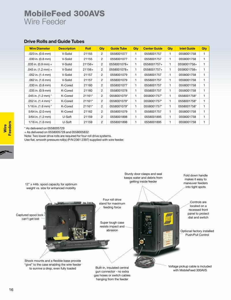
Drive Rolls and Guide Tubes
MobileFeed 300AVSWire Feeder
Controls are located on a
recessed front panel to protect dial and switch
Sturdy door clasps and seal keeps water and debris from
getting inside feeder
Super tough case resists impact and
abrasion
Fold down handle makes it easy to
maneuver feeders into tight spots
Built-in, insulated central gun connector - no extra
gas hoses or switch cables hanging from the feeder
Voltage pickup cable is included with MobileFeed 300AVS
12" x 44lb. spool capacity for optimum weight vs. size for enhanced mobility
Shock mounts and a flexible base provide “give” to the case enabling the wire feeder
to survive a drop, even fully loaded
Captured spool lock - can't get lost
Four roll drive stand for maximum
feeding force
Optional factory installed Push/Pull Control
* As delivered on 0558005729 + As delivered on 0558005728 and 0558005832 Note: Two lower drive rolls are required for four roll drive systems. Use flat, smooth pressure roll(s) (P/N 2361 2397) supplied with wire feeder.
Wire Diameter Description Roll Qty Guide Tube Qty Center Guide Qty Inlet Guide Qty
.023 in. (0.6 mm) V-Solid 21155 2 0558001077 1 0558001757 1 0558001758 1
.030 in. (0.8 mm) V-Solid 21155 2 0558001077 1 0558001757 1 0558001758 1
.035 in. (0.9 mm) + V-Solid 21156+ 2 0558001078+ 1 0558001757+ 1 0558001758+ 1
.045 in. (1.2 mm) + V-Solid 21156+ 2 0558001078+ 1 0558001757+ 1 0558001758+ 1
.052 in. (1.4 mm) V-Solid 21157 2 0558001079 1 0558001757 1 0558001758 1
.062 in. (1.6 mm) V-Solid 21157 2 0558001079 1 0558001757 1 0558001758 1
.030 in. (0.8 mm) K-Cored 21160 2 0558001077 1 0558001757 1 0558001758 1
.035 in. (0.9 mm) K-Cored 21160 2 0558001078 1 0558001757 1 0558001758 1
.045 in. (1.2 mm) * K-Cored 21161* 2 0558001079* 1 0558001757* 1 0558001758* 1
.052 in. (1.4 mm) * K-Cored 21161* 2 0558001079* 1 0558001757* 1 0558001758* 1
1/16 in. (1.6 mm) * K-Cored 21161* 2 0558001079* 1 0558001757* 1 0558001758* 1
5/64 in. (2.0 mm) K-Cored 21162 2 0558001079 1 0558001757 1 0558001758 1
3/64 in. (1.2 mm) U-Soft 21159 2 0558001898 1 0558001895 1 0558001758 1
1/16 in. (1.6 mm) U-Soft 21159 2 0558001898 1 0558001895 1 0558001758 1
17
Wire
Feeders
Origo™ Feed 304 M13u Wire Feeder
� Remote voltage control, allows local setting of power source voltage output
�Wire feed speed, accurate graduated dial shows settings in 50 ipm (1 m/min.) increments
� Adjustable burn-back time to correct stick-out and reduce wear of contact tips
� 2/4 stroke, helps minimize operator fatigue by optionally selecting trigger lock in the 4 stroke mode
� Inching/Gas Purge - Inching eliminates unsafe trigger pulls to load wire. Gas Purge ensures a clean start with pure shield gas
� Creep start - simplifies start/stop and gradual feed of wire to optimize the starts.
� Quick connectors - shortest possible set-up times. No tools required to change feed rolls, connect gas hose, weld cable or control cable.
With its galvanized metal casing, the ESAB Origo Feed is ideal for use in tough environments. Electronically controlled feeding gives accurate and stable arc. The four wheel roll feeder mechanism with grooves in both feed roll and pressure roll gives stable feeding and low wear on the wire - to avoid operational disturbance.
The feeders are available with either 1.18 in. (30 mm) rolls for wires from .023 in. (0.6 mm) up to 5/64 in. (2.0 mm). All operating adjustments are made on the front panel of the feeder, giving a good overview of the settings.
The front panel of the M13u is equipped with switches for inching/gas purge, 2/4 stroke and creep start. A wire feed speed knob with accurate graduated dial and adjustable burn-back are included. A remote voltage control is provided with 10 graduations from min. to max. settings. The panel is easy to operate with accurate setting that suits different needs and demands.
Extra versatility can be provided by utilizing one of the following mounting options for the Origo™ Feed. Counterbalance & Mast, Wheel Kit or Hanging Bracket.
Ordering InformationBasic Packages Origo Feed 304 M13u with QC ........................... 0558101668 Origo Feed 304 M13u with lugs .......................... 0558101669Feeder Only Origo Feed 304 M13u .......................................... 0459115860Basic package includes: feeder, 400 A torch, cables, R-33 flowmeter.
Feeder AccessoriesWheel kit .....................................................................0458707880Strain relief for welding torch ...................................0457341881Feeder strain relief for connection cables ..............0459234880Lifting eye....................................................................0458706880Quick connector MarathonPac ................................0558002354Adapter for 11 lb spool ..............................................0455410001Steel spool cover .......................................................0459431880Counter-balance Mini boom For 12" spools ........................................................0458705880 For 18" spools ........................................................0458705882Extension bracket for 60 lb coil ................................0459233880Coil adapter (requires 0459233880).................................... 34323Spool cover Plastic 12" ................................................................0458674880 Steel 12" ..................................................................0459431880
Connection Cable Sets Air-Cooled Torch 5.5 ft. (1.7 m) ............................................................0349312460 16.4 ft. (5.0 m) ..........................................................0349312461 32.8 ft. (10.0 m) ........................................................0349312462 49.2 ft. (15.0 m) ........................................................0349312463 82.0 ft. (25.0 m) ........................................................0349312464 114.8 ft. (35.0 m) ......................................................0349312465Includes: control cable, electrode cable, and gas hose.
TorchesGunMaster 400cc 25 ft. (7.6 m) Basic ...................................................0558001674 12 ft. (3.6 m) x .035–.045 in. .....................................0558001667 15 ft. (4.5 m) x .035–.045 in. ....................................0558001669 15 ft. (4.5 m) x .052–1/16 in. ....................................0558001670See ARC-23095 for additional information.
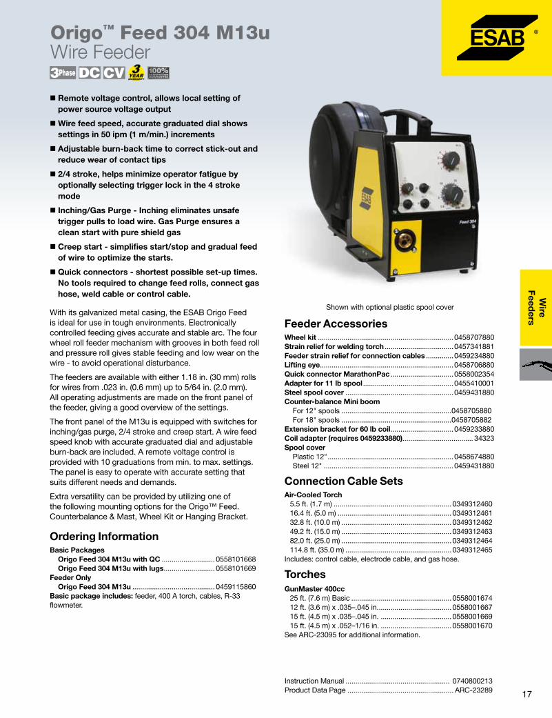
Shown with optional plastic spool cover
Instruction Manual ..................................................... 0740800213Product Data Page ...................................................... ARC-23289
18
Wir
eFe
eder
sOrigo™ Feed 304 M13u Wire Feeder
Feeder Data
* Requires optional accessories
� Remote voltage control
�Wire feed speed
� 2/4 stroke – simplifies handling of the welding torch
� Adjustable burn-back time
� Gas purge/wire inching (standard)
� Creep start
Panel (MMC) functions
Wear Parts
Power Supply
Wire Spool Capacity
Max. Spool Diameter Wire Feed Speed
Dimension (L x W x H) Weight Wire Dimensions
42 VAC, 50/60 Hz
44 lb (18 kg) or 66 lb (30 kg)*
12 in. (300 mm) (enclosed)
32-1000 in./min. (0.8-25.0 m/min.)
27.1 x 10.8 x 16.1 in. (690 x 275 x 420 mm)
33 lb (15 kg) Steel .023–.062 in. (0.6–1.6 mm) Stainless steel .023–.062 in. (0.6–1.6 mm) Aluminum .030–.062 in. (0.8–1.6 mm) Cored wire . 035–.078 in. (0.9–2 mm)
Wire Diameter (in.) Wire Type
1 Feeder Roller (4 required)
2 Inlet Nozzle
3 Intermediate
Nozzle4
Outlet NozzleGroove
Type Marking
023 / .030 Fe, Ss, C 0459052001 0455049001 0455072002 0469837880 V 0.6 S2 / 0.8 S2
.030 / .035 -.040 Fe, Ss, C 0459052002 0455049001 0455072002 0469837880 V 0.8 S2 / 1.0 S2
.035 - .040 / .045* Fe, Ss, C 0459 052003 0455049001 0455072002 0469837880 V 1.0 S2 / 1.2 S2
.052 / .063 Fe, Ss, C 0459052013 0455049001 0455072002 0469837880 V 1.4 S2 / 1.6 S2
.035 -.040 / .045 C 0558002352 0455049001 0455072002 0469837880 V-K 1.0 R2 / 1.2 R2
.045 / .045 C 0458825010 0455049001 0455072002 0469837880 V-K 1.2 R2 / 1.2 R2
.045 / .052 C 37319 0455049001 0455072002 0469837880 V-K 1.2 R2 / 1.4 R2
1/16 - 5/64 C 37320 0455049001 0455072002 0469837880 V-K 1.6 R2
.035 - 3/64 Al 36860 0455049001 0456615001 0469837881 U 0.8 A2 / 1.0 A2
3/64 - 1/16 Al 36861 0455049001 0456615001 0469837881 U 1.2 A2 / 1.6 A2
C = cored wire * as delivered K = knurled groove
19
Wire
Feeders
Origo™ Feed 3004 MA23 with Mig 4002c/6502c Power Supply
Optimum welding solutions for easy setup and operation in GMAW/FCAW/SMAW.With its galvanized metal casing, the ESAB Origo Feed 3004 is ideal for use in tough environments. Electronically controlled feeding gives accurate and stable arc. The four-wheel roller feeder mechanism with grooves in both feed roll and pressure roll gives stable feeding and low wear on the wire – to avoid operational disturbances.
The feeder has rolls with a diameter of 1.18 in. (30 mm) for wires up to .062 in. (1.6 mm) diameter. All adjustments are made on the man-machine communication panels (MMC) of the feeder, giving a good overview of the settings.
With the Origo Feed 3004, you have your choice of power sources. The MIG 4002c and 6502c switching converter (chopper) power sources are all intended for heavy-duty applications. The units are easily transported, and the digital (CANbus) communications and control system reduces the need for cables.
� Quick connectors – reduces setup times
�Meets IEC 60974-5 safety standard with low voltage (42 VAC) operations and overload protection circuit to help eliminate breakdowns
� TrueArcVoltage™ System – measures the correct arc voltage value independent of the length of the connection cable or welding torch
� Can be equipped with a counterbalance device, lifting eye, or wheel kit for increased mobility
� Burnback
� Continuous adjustable inductor
Ordering InformationReady to Weld Packages MIG 4002c Origo Feed 3004 MA23 ........................0558101332 MIG 6502c Origo Feed 3004 MA23 ........................0558101336Basic Packages MIG 4002c Origo Feed 3004 MA23 .....................0558101333 MIG 6502c Origo Feed 3004 MA23 .....................0558101337Ready to Weld package includes: power source, feeder, 15 ft. (4.5 m) 400 A torch, 5.5 ft. (1.7 m) connection cable set, 16.4 ft. (5 m) work cable, reg. flowmeter Ar CO2.Basic package includes: power source, feeder, 15 ft. (4.5 m) 400 A torch.
Connection Cable Sets Air-Cooled Torch, 10 pole 5.5 ft. (1.7 m) ............................................................0349312450 16.4 ft. (5.0 m) ..........................................................0349312451 32.8 ft. (10.0 m) ........................................................0349312452 49.2 ft. (15.0 m) ........................................................0349312453 82.0 ft. (25.0 m) ........................................................0349312454 114.8 ft. (35.0 m) ......................................................0349312455Includes: control cable, electrode cable, and gas hose.
TorchesGunMaster 400cc 25 ft. (7.6 m) Basic ...................................................0558001674 12 ft. (3.6 m) x .035–.045 in. .....................................0558001667 15 ft. (4.5 m) x .035–.045 in. ....................................0558001669 15 ft. (4.5 m) x .052–1/16 in. ....................................0558001670See ARC-23095 for additional information.
Instruction Manual Origo Feed 3004 ...................................................0444 408 187 MA23/MA24 ..........................................................0460 454 187 MIG 4002/6502 .....................................................0349 301 162Product Data Page ...................................................... ARC-23275
Feeder AccessoriesWheel kit .....................................................................0458707880Strain relief for welding torch ...................................0457341881Feeder strain relief for connection cables ..............0459234880Lifting eye....................................................................0458706880Quick connector MarathonPac ................................0558002354Adapter for 11 lb spool ..............................................0455410001Steel spool cover .......................................................0459431880Counter-balance Mini boom For 12" spools .........................................................0458705880 For 18" spools .........................................................0458705882Extension bracket for 60 lb coil ................................0459233880Coil adapter .......................................................................... 34323Remote control MTA1 CAN .......................................0459491880Remote connection cable for CAN 10p ...................0459960880Miggy Track remote adapter ....................................0459681880 Push Pull adapter kit..................................................0459681881

20
Wir
eFe
eder
sOrigo™ Feed 3004 MA23 with Mig 4002c/6502c Power Supply
� Process select
� 2/4 stroke – simplifies handling of the welding torch
� Gas pre/post flow
� Digital V/A meters
� Gas purge/wire inching
�Memory for 3-parameter set
* Requires optional accessories
Feeder Data
Panel (MMC) functions
Wear Parts
Power Supply
Wire Spool Capacity
Max. Spool Diameter Wire Feed Speed
Dimension (L x W x H)
Weight Enclosed Wire Dimensions
42 VAC, 50/60 Hz
44 lb (19 kg) or 60 lb (27 kg)*
12 in. (300 mm) (enclosed)
32-1000 in./min. (0.8-25.0 m/min.)
27.1 x 10.8 x 16.1 in. (690 x 275 x 420 mm)
33 lb (15 kg) Steel .023–.062 in. (0.6–1.6 mm) Stainless steel .023–.062 in. (0.6–1.6 mm) Aluminum .040–.062 in. (1.0–1.6 mm) Cored wire . 030–.062 in. (0.8–1.6 mm)
Wire Diameter (in.) Wire Type
1 Feeder Roller (4 required)
2 Inlet Nozzle
3 Intermediate
Nozzle4
Outlet NozzleGroove
Type Marking
023 / .030 Fe, Ss, C 0459052001 0455049001 0455072002 0469837880 V 0.6 S2 / 0.8 S2
.030 / .035 -.040 Fe, Ss, C 0459052002 0455049001 0455072002 0469837880 V 0.8 S2 / 1.0 S2
.035 - .040 / .045* Fe, Ss, C 0459 052003 0455049001 0455072002 0469837880 V 1.0 S2 / 1.2 S2
.052 / .063 Fe, Ss, C 0459052013 0455049001 0455072002 0469837880 V 1.4 S2 / 1.6 S2
.035 -.040 / .045 C 0558002352 0455049001 0455072002 0469837880 V-K 1.0 R2 / 1.2 R2
.045 / .045 C 0458825010 0455049001 0455072002 0469837880 V-K 1.2 R2 / 1.2 R2
.045 / .052 C 37319 0455049001 0455072002 0469837880 V-K 1.2 R2 / 1.4 R2
1/16 - 5/64 C 37320 0455049001 0455072002 0469837880 V-K 1.6 R2
.035 - 3/64 Al 36860 0455049001 0456615001 0469837881 U 0.8 A2 / 1.0 A2
3/64 - 1/16 Al 36861 0455049001 0456615001 0469837881 U 1.2 A2 / 1.6 A2
C = cored wire * as delivered K = knurled groove

21
Wire
Feeders
Origo™ Feed 3004 MA23 with Mig 4002c/6502c Power Supply
�Multi-voltage – ready to work anywhere
� Energy saving mode saves power
� Outstanding arc across total power range
� Robust power technology
� Dust filter to prevent grinding-dust and metal particles from entering the chassis (optional)
� Undercarriage standard
Power Source Features
Specifications
Air filter ........................................................................0349302252Electrode holder assembly QC – 15 ft. .............................. 21226Power source strain relief for connection cables ..0349311700Cable and torch holder ..............................................0349303362Dual cylinder tray kit ..................................................0349312780
Dual feeder manual switch over control for Origo feed MA23 ........................................................0588001819Work cable assembly 15 ft. w/clamp 50 mm OKC ............................................... 36253 32 ft. w/clamp 50 mm OKC .....................................0558008683MMC cable to power supply ....................................0458357885
Power Source Accessories
4002c 6502c
Input voltage 230/460 V 3 ph 60 Hz 230/460 V 3 ph 60 Hz
Permitted load
60% duty cycle 400 A / 34 V 650 A / 44 V
100% duty cycle 310 A / 30 V 500 A / 39 V
Primary current
60% duty cycle 56/26 A 103/47 A
100% duty cycle 43/20 A 80/37A
Setting range (DC) GMAW/FCAW (MIG/MAG) 16–400 A / 8–60 V 16–650 A / 8–60 V
Setting range (STICK) 16-400A 16-650A
Open circuit voltage GMAW/FCAW (MIG/MAG) 62 V 62 V
Open circuit voltage SMAW (STICK) 68 V 68 V
Open circuit power 500 W 670 W
In energy saving mode, 15 min. after welding 60 W 60 W
Power factor at maximum current 0.88 0.90
Efficiency at maximum current 70% 76%
Control voltage 42 V, 50/60 Hz 42 V, 50/60 Hz
Dimensions L x W x H 32.6 x 25.1 x 32.8 in. (830 x 640 x 835 mm)
32.6 x 25.1 x 32.8 in. (830 x 640 x 835 mm)
Weight 328 lb (149 kg) 489 lb (222 kg)
Weight with cooling unit 359 lb (163 kg) 520 lb (236 kg)
Operating temperature 14 to 104°F (-10 to 40°C) 14 to 104°F (-10 to 40°C)
Enclosure class IP 23 IP 23
22
Wir
eFe
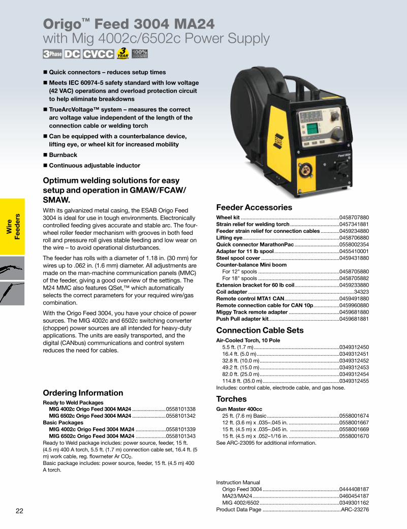
eder
sOrigo™ Feed 3004 MA24 with Mig 4002c/6502c Power Supply
Optimum welding solutions for easy setup and operation in GMAW/FCAW/SMAW.With its galvanized metal casing, the ESAB Origo Feed 3004 is ideal for use in tough environments. Electronically controlled feeding gives accurate and stable arc. The four-wheel roller feeder mechanism with grooves in both feed roll and pressure roll gives stable feeding and low wear on the wire – to avoid operational disturbances.
The feeder has rolls with a diameter of 1.18 in. (30 mm) for wires up to .062 in. (1.6 mm) diameter. All adjustments are made on the man-machine communication panels (MMC) of the feeder, giving a good overview of the settings. The M24 MMC also features QSet,™ which automatically selects the correct parameters for your required wire/gas combination.
With the Origo Feed 3004, you have your choice of power sources. The MIG 4002c and 6502c switching converter (chopper) power sources are all intended for heavy-duty applications. The units are easily transported, and the digital (CANbus) communications and control system reduces the need for cables.
� Quick connectors – reduces setup times
�Meets IEC 60974-5 safety standard with low voltage (42 VAC) operations and overload protection circuit to help eliminate breakdowns
� TrueArcVoltage™ system – measures the correct arc voltage value independent of the length of the connection cable or welding torch
� Can be equipped with a counterbalance device, lifting eye, or wheel kit for increased mobility
� Burnback
� Continuous adjustable inductor
Ordering InformationReady to Weld Packages MIG 4002c Origo Feed 3004 MA24 ........................0558101338 MIG 6502c Origo Feed 3004 MA24 ........................0558101342Basic Packages MIG 4002c Origo Feed 3004 MA24 .....................0558101339 MIG 6502c Origo Feed 3004 MA24 .....................0558101343Ready to Weld package includes: power source, feeder, 15 ft. (4.5 m) 400 A torch, 5.5 ft. (1.7 m) connection cable set, 16.4 ft. (5 m) work cable, reg. flowmeter Ar CO2.Basic package includes: power source, feeder, 15 ft. (4.5 m) 400 A torch.
Connection Cable Sets Air-Cooled Torch, 10 Pole 5.5 ft. (1.7 m) ...........................................................0349312450 16.4 ft. (5.0 m) .........................................................0349312451 32.8 ft. (10.0 m) .......................................................0349312452 49.2 ft. (15.0 m) .......................................................0349312453 82.0 ft. (25.0 m) .......................................................0349312454 114.8 ft. (35.0 m) .....................................................0349312455Includes: control cable, electrode cable, and gas hose.
TorchesGun Master 400cc 25 ft. (7.6 m) Basic ..................................................0558001674 12 ft. (3.6 m) x .035–.045 in. ...................................0558001667 15 ft. (4.5 m) x .035–.045 in. ..................................0558001669 15 ft. (4.5 m) x .052–1/16 in. ...................................0558001670 See ARC-23095 for additional information.
Instruction Manual Origo Feed 3004 .....................................................0444408187 MA23/MA24 ............................................................0460454187 MIG 4002/6502 .......................................................0349301162Product Data Page ......................................................ARC-23276
Feeder AccessoriesWheel kit ....................................................................0458707880Strain relief for welding torch ..................................0457341881Feeder strain relief for connection cables .............0459234880Lifting eye...................................................................0458706880Quick connector MarathonPac ...............................0558002354Adapter for 11 lb spool .............................................0455410001Steel spool cover ......................................................0459431880Counter-balance Mini boom For 12" spools ........................................................0458705880 For 18" spools ........................................................0458705882Extension bracket for 60 lb coil ...............................0459233880Coil adapter .........................................................................34323Remote control MTA1 CAN ......................................0459491880Remote connection cable for CAN 10p ..................0459960880Miggy Track remote adapter ...................................0459681880 Push Pull adapter kit.................................................0459681881
23
Wire
Feeders
Origo™ Feed 3004 MA24 with Mig 4002c/6502c Power Supply
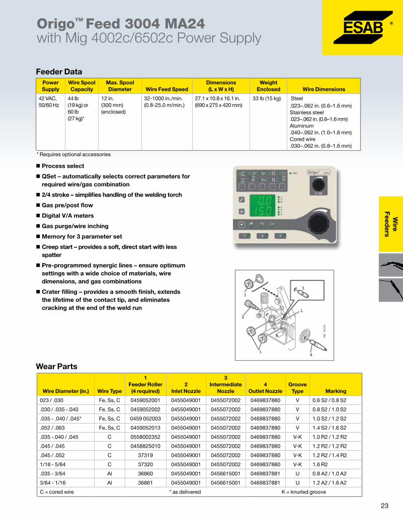
� Process select
� QSet – automatically selects correct parameters for required wire/gas combination
� 2/4 stroke – simplifies handling of the welding torch
� Gas pre/post flow
� Digital V/A meters
� Gas purge/wire inching
�Memory for 3 parameter set
� Creep start – provides a soft, direct start with less spatter
� Pre-programmed synergic lines – ensure optimum settings with a wide choice of materials, wire dimensions, and gas combinations
� Crater filling – provides a smooth finish, extends the lifetime of the contact tip, and eliminates cracking at the end of the weld run
Feeder Data
Wear Parts
* Requires optional accessories
Power Supply
Wire Spool Capacity
Max. Spool Diameter Wire Feed Speed
Dimensions (L x W x H)
Weight Enclosed Wire Dimensions
42 VAC, 50/60 Hz
44 lb (19 kg) or 60 lb (27 kg)*
12 in. (300 mm) (enclosed)
32-1000 in./min. (0.8-25.0 m/min.)
27.1 x 10.8 x 16.1 in. (690 x 275 x 420 mm)
33 lb (15 kg) Steel .023–.062 in. (0.6–1.6 mm) Stainless steel .023–.062 in. (0.6–1.6 mm) Aluminum .040–.062 in. (1.0–1.6 mm) Cored wire .030–.062 in. (0.8–1.6 mm)
Wire Diameter (in.) Wire Type
1 Feeder Roller (4 required)
2 Inlet Nozzle
3 Intermediate
Nozzle4
Outlet NozzleGroove
Type Marking
023 / .030 Fe, Ss, C 0459052001 0455049001 0455072002 0469837880 V 0.6 S2 / 0.8 S2
.030 / .035 -.040 Fe, Ss, C 0459052002 0455049001 0455072002 0469837880 V 0.8 S2 / 1.0 S2
.035 - .040 / .045* Fe, Ss, C 0459 052003 0455049001 0455072002 0469837880 V 1.0 S2 / 1.2 S2
.052 / .063 Fe, Ss, C 0459052013 0455049001 0455072002 0469837880 V 1.4 S2 / 1.6 S2
.035 -.040 / .045 C 0558002352 0455049001 0455072002 0469837880 V-K 1.0 R2 / 1.2 R2
.045 / .045 C 0458825010 0455049001 0455072002 0469837880 V-K 1.2 R2 / 1.2 R2
.045 / .052 C 37319 0455049001 0455072002 0469837880 V-K 1.2 R2 / 1.4 R2
1/16 - 5/64 C 37320 0455049001 0455072002 0469837880 V-K 1.6 R2
.035 - 3/64 Al 36860 0455049001 0456615001 0469837881 U 0.8 A2 / 1.0 A2
3/64 - 1/16 Al 36861 0455049001 0456615001 0469837881 U 1.2 A2 / 1.6 A2
C = cored wire * as delivered K = knurled groove
24
Wir
eFe
eder
s
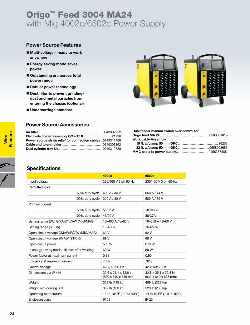
�Multi-voltage – ready to work anywhere
� Energy saving mode saves power
� Outstanding arc across total power range
� Robust power technology
� Dust filter to prevent grinding-dust and metal particles from entering the chassis (optional)
� Undercarriage standard
Origo™ Feed 3004 MA24 with Mig 4002c/6502c Power Supply
Power Source Features
Specifications
Air filter ........................................................................0349302252Electrode holder assembly QC – 15 ft. .............................. 21226Power source strain relief for connection cables ..0349311700Cable and torch holder ..............................................0349303362Dual cylinder tray kit ..................................................0349312780
Dual feeder manual switch over control for Origo feed MA 24 .......................................................0588001819Work cable Assembly 15 ft. w/clamp 50 mm OKC ............................................. 36253 32 ft. w/clamp 50 mm OKC ...................................0558008683MMC cable to power supply.... ................................0458357885
Power Source Accessories
4002c 6502c
Input voltage 230/460 V 3 ph 60 Hz 230/460 V 3 ph 60 Hz
Permitted load
60% duty cycle 400 A / 34 V 650 A / 44 V
100% duty cycle 310 A / 30 V 500 A / 39 V
Primary current
60% duty cycle 56/26 A 103/47 A
100% duty cycle 43/20 A 80/37A
Setting range (DC) GMAW/FCAW (MIG/MAG) 16–400 A / 8–60 V 16–650 A / 8–60 V
Setting range (STICK) 16-400A 16-650A
Open circuit voltage GMAW/FCAW (MIG/MAG) 62 V 62 V
Open circuit voltage SMAW (STICK) 68 V 68 V
Open circuit power 500 W 670 W
In energy saving mode, 15 min. after welding 60 W 60 W
Power factor at maximum current 0.88 0.90
Efficiency at maximum current 70% 76%
Control voltage 42 V, 50/60 Hz 42 V, 50/60 Hz
Dimensions L x W x H 32.6 x 25.1 x 32.8 in. (830 x 640 x 835 mm)
32.6 x 25.1 x 32.8 in. (830 x 640 x 835 mm)
Weight 328 lb (149 kg) 489 lb (222 kg)
Weight with cooling unit 359 lb (163 kg) 520 lb (236 kg)
Operating temperature 14 to 104°F (-10 to 40°C) 14 to 104°F (-10 to 40°C)
Enclosure class IP 23 IP 23
25
Wire
Feeders
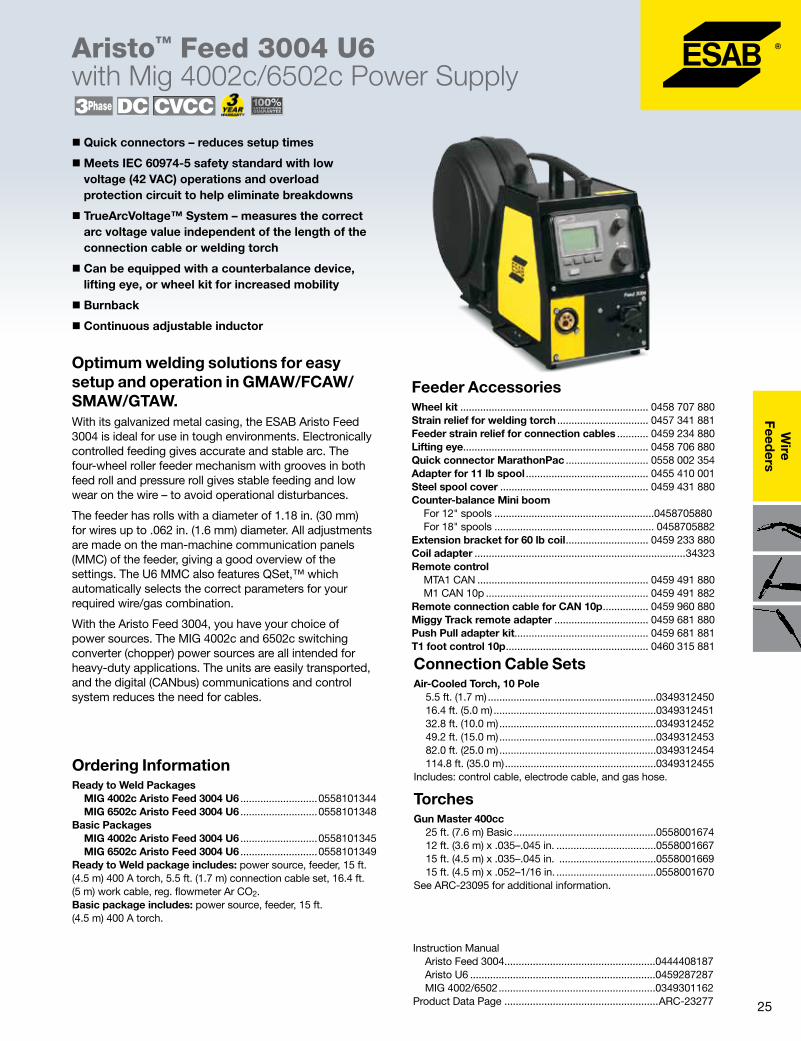
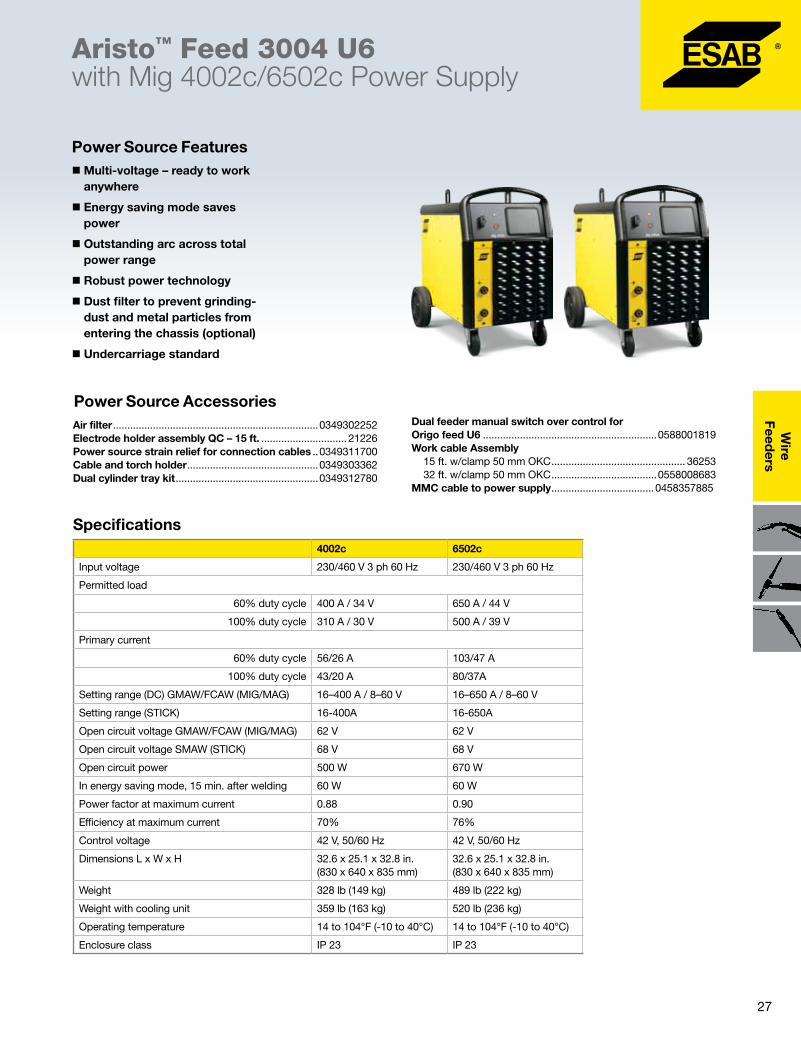
Aristo™ Feed 3004 U6 with Mig 4002c/6502c Power Supply
Optimum welding solutions for easy setup and operation in GMAW/FCAW/SMAW/GTAW.With its galvanized metal casing, the ESAB Aristo Feed 3004 is ideal for use in tough environments. Electronically controlled feeding gives accurate and stable arc. The four-wheel roller feeder mechanism with grooves in both feed roll and pressure roll gives stable feeding and low wear on the wire – to avoid operational disturbances.
The feeder has rolls with a diameter of 1.18 in. (30 mm) for wires up to .062 in. (1.6 mm) diameter. All adjustments are made on the man-machine communication panels (MMC) of the feeder, giving a good overview of the settings. The U6 MMC also features QSet,™ which automatically selects the correct parameters for your required wire/gas combination.
With the Aristo Feed 3004, you have your choice of power sources. The MIG 4002c and 6502c switching converter (chopper) power sources are all intended for heavy-duty applications. The units are easily transported, and the digital (CANbus) communications and control system reduces the need for cables.
Ordering InformationReady to Weld Packages MIG 4002c Aristo Feed 3004 U6 ...........................0558101344 MIG 6502c Aristo Feed 3004 U6 ...........................0558101348Basic Packages MIG 4002c Aristo Feed 3004 U6 ...........................0558101345 MIG 6502c Aristo Feed 3004 U6 ...........................0558101349Ready to Weld package includes: power source, feeder, 15 ft. (4.5 m) 400 A torch, 5.5 ft. (1.7 m) connection cable set, 16.4 ft. (5 m) work cable, reg. flowmeter Ar CO2.Basic package includes: power source, feeder, 15 ft. (4.5 m) 400 A torch.
� Quick connectors – reduces setup times
�Meets IEC 60974-5 safety standard with low voltage (42 VAC) operations and overload protection circuit to help eliminate breakdowns
� TrueArcVoltage™ System – measures the correct arc voltage value independent of the length of the connection cable or welding torch
� Can be equipped with a counterbalance device, lifting eye, or wheel kit for increased mobility
� Burnback
� Continuous adjustable inductor
Feeder AccessoriesWheel kit .................................................................. 0458 707 880Strain relief for welding torch ................................ 0457 341 881Feeder strain relief for connection cables ........... 0459 234 880Lifting eye................................................................. 0458 706 880Quick connector MarathonPac ............................. 0558 002 354Adapter for 11 lb spool ........................................... 0455 410 001Steel spool cover .................................................... 0459 431 880Counter-balance Mini boom For 12" spools ........................................................0458705880 For 18" spools ........................................................ 0458705882 Extension bracket for 60 lb coil ............................. 0459 233 880Coil adapter ..........................................................................34323Remote control MTA1 CAN ............................................................ 0459 491 880 M1 CAN 10p ......................................................... 0459 491 882Remote connection cable for CAN 10p ................ 0459 960 880Miggy Track remote adapter ................................. 0459 681 880Push Pull adapter kit............................................... 0459 681 881T1 foot control 10p .................................................. 0460 315 881
Instruction Manual Aristo Feed 3004.....................................................0444408187 Aristo U6 .................................................................0459287287 MIG 4002/6502 .......................................................0349301162Product Data Page ......................................................ARC-23277
Connection Cable Sets Air-Cooled Torch, 10 Pole 5.5 ft. (1.7 m) ...........................................................0349312450 16.4 ft. (5.0 m) .........................................................0349312451 32.8 ft. (10.0 m) .......................................................0349312452 49.2 ft. (15.0 m) .......................................................0349312453 82.0 ft. (25.0 m) .......................................................0349312454 114.8 ft. (35.0 m) .....................................................0349312455Includes: control cable, electrode cable, and gas hose.
TorchesGun Master 400cc 25 ft. (7.6 m) Basic ..................................................0558001674 12 ft. (3.6 m) x .035–.045 in. ...................................0558001667 15 ft. (4.5 m) x .035–.045 in. ..................................0558001669 15 ft. (4.5 m) x .052–1/16 in. ...................................0558001670 See ARC-23095 for additional information.
26
Wir
eFe
eder
s
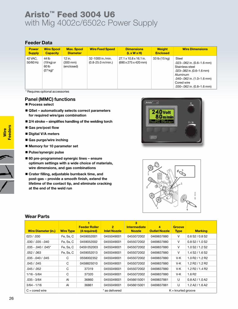
� Process select
� QSet – automatically selects correct parameters for required wire/gas combination
� 2/4 stroke – simplifies handling of the welding torch
� Gas pre/post flow
� Digital V/A meters
� Gas purge/wire inching
�Memory for 10 parameter set
� Pulse/synergic pulse
� 60 pre-programmed synergic lines – ensure optimum settings with a wide choice of materials, wire dimensions, and gas combinations
� Crater filling, adjustable burnback time, and post-gas – provide a smooth finish, extend the lifetime of the contact tip, and eliminate cracking at the end of the weld run
Aristo™ Feed 3004 U6 with Mig 4002c/6502c Power Supply
Panel (MMC) functions
Feeder Data
Wear Parts
* Requires optional accessories
Power Supply
Wire Spool Capacity
Max. Spool Diameter
Wire Feed Speed Dimensions (L x W x H)
Weight Enclosed
Wire Dimensions
42 VAC, 50/60 Hz
44 lb (19 kg) or 60 lb (27 kg)*
12 in. (300 mm) (enclosed)
32-1000 in./min. (0.8-25.0 m/min.)
27.1 x 10.8 x 16.1 in. (690 x 275 x 420 mm)
33 lb (15 kg) Steel .023–.062 in. (0.6–1.6 mm) Stainless steel .023–.062 in. (0.6–1.6 mm) Aluminum .040–.062 in. (1.0–1.6 mm) Cored wire .030–.062 in. (0.8–1.6 mm)
Wire Diameter (in.) Wire Type
1 Feeder Roller (4 required)
2 Inlet Nozzle
3 Intermediate
Nozzle4
Outlet NozzleGroove
Type Marking
023 / .030 Fe, Ss, C 0459052001 0455049001 0455072002 0469837880 V 0.6 S2 / 0.8 S2
.030 / .035 -.040 Fe, Ss, C 0459052002 0455049001 0455072002 0469837880 V 0.8 S2 / 1.0 S2
.035 - .040 / .045* Fe, Ss, C 0459 052003 0455049001 0455072002 0469837880 V 1.0 S2 / 1.2 S2
.052 / .063 Fe, Ss, C 0459052013 0455049001 0455072002 0469837880 V 1.4 S2 / 1.6 S2
.035 -.040 / .045 C 0558002352 0455049001 0455072002 0469837880 V-K 1.0 R2 / 1.2 R2
.045 / .045 C 0458825010 0455049001 0455072002 0469837880 V-K 1.2 R2 / 1.2 R2
.045 / .052 C 37319 0455049001 0455072002 0469837880 V-K 1.2 R2 / 1.4 R2
1/16 - 5/64 C 37320 0455049001 0455072002 0469837880 V-K 1.6 R2
.035 - 3/64 Al 36860 0455049001 0456615001 0469837881 U 0.8 A2 / 1.0 A2
3/64 - 1/16 Al 36861 0455049001 0456615001 0469837881 U 1.2 A2 / 1.6 A2
C = cored wire * as delivered K = knurled groove
27
Wire
Feeders
�Multi-voltage – ready to work anywhere
� Energy saving mode saves power
� Outstanding arc across total power range
� Robust power technology
� Dust filter to prevent grinding-dust and metal particles from entering the chassis (optional)
� Undercarriage standard
Power Source Features
Specifications
Air filter ........................................................................0349302252Electrode holder assembly QC – 15 ft. .............................. 21226Power source strain relief for connection cables ..0349311700Cable and torch holder ..............................................0349303362Dual cylinder tray kit ..................................................0349312780
Dual feeder manual switch over control for Origo feed U6 .............................................................0588001819Work cable Assembly 15 ft. w/clamp 50 mm OKC ............................................... 36253 32 ft. w/clamp 50 mm OKC .....................................0558008683MMC cable to power supply ....................................0458357885
Power Source Accessories
Aristo™ Feed 3004 U6 with Mig 4002c/6502c Power Supply
4002c 6502c
Input voltage 230/460 V 3 ph 60 Hz 230/460 V 3 ph 60 Hz
Permitted load
60% duty cycle 400 A / 34 V 650 A / 44 V
100% duty cycle 310 A / 30 V 500 A / 39 V
Primary current
60% duty cycle 56/26 A 103/47 A
100% duty cycle 43/20 A 80/37A
Setting range (DC) GMAW/FCAW (MIG/MAG) 16–400 A / 8–60 V 16–650 A / 8–60 V
Setting range (STICK) 16-400A 16-650A
Open circuit voltage GMAW/FCAW (MIG/MAG) 62 V 62 V
Open circuit voltage SMAW (STICK) 68 V 68 V
Open circuit power 500 W 670 W
In energy saving mode, 15 min. after welding 60 W 60 W
Power factor at maximum current 0.88 0.90
Efficiency at maximum current 70% 76%
Control voltage 42 V, 50/60 Hz 42 V, 50/60 Hz
Dimensions L x W x H 32.6 x 25.1 x 32.8 in. (830 x 640 x 835 mm)
32.6 x 25.1 x 32.8 in. (830 x 640 x 835 mm)
Weight 328 lb (149 kg) 489 lb (222 kg)
Weight with cooling unit 359 lb (163 kg) 520 lb (236 kg)
Operating temperature 14 to 104°F (-10 to 40°C) 14 to 104°F (-10 to 40°C)
Enclosure class IP 23 IP 23

28
Wir
eFe
eder
s
Optimum welding solutions for easy setup and operation in GMAW/FCAW/SMAW/GTAW.With its galvanized metal casing, the ESAB Aristo Feed 3004 is ideal for use in tough environments. Electronically controlled feeding gives accurate and stable arc. The four-wheel roller feeder mechanism with grooves in both feed roll and pressure roll gives stable feeding and low wear on the wire – to avoid operational disturbances.
The feeder has rolls with a diameter of 1.18 in. (30 mm) for wires up to .062 in. (1.6 mm) diameter. All adjustments are made on the man-machine communication panels (MMC) of the feeder, giving a good overview of the settings. The U82 Plus MMC also features QSet, which automatically selects the correct parameters for your required wire/gas combination.
With the Aristo Feed 3004, you have your choice of power sources. The MIG 4002c and 6502c switching converter (chopper) power sources are all intended for heavy-duty applications. The units are easily transported, and the digital (CANbus) communications and control system reduces the need for cables.
Ordering InformationReady to Weld Packages MIG 4002c Aristo Feed 3004 U82 Plus ...........0558101354 MIG 6502c Aristo Feed 3004 U82 Plus ...........0558101358 MIG 4002c Dual Aristo Feed 3004 .................0558101366 MIG 6502c Dual Aristo Feed 3004 ..................0558101368Basic Packages MIG 4002c Aristo Feed 3004 U82 Plus ...........0558101355 MIG 6502c Aristo Feed 3004 U82 Plus ...........0558101359Ready to Weld package includes: power source, feeder, 15 ft. (4.5 m) 400 A torch, 5.5 ft. (1.7 m) connection cable set, 16.4 ft. (5 m) work cable, reg. flowmeter Ar CO2.Basic package includes: power source, feeder, 15 ft. (4.5 m) 400 A torch.
� Quick connectors – reduces setup times
�Meets IEC 60974-5 safety standard with low voltage (42 VAC) operations and overload protection circuit to help eliminate breakdowns
� TrueArcVoltage™ System – measures the correct arc voltage value independent of the length of the connection cable or welding torch
� Can be equipped with a counterbalance device, lifting eye, or wheel kit for increased mobility
� Burnback
� Continuous adjustable inductor
Feeder AccessoriesWheel kit ....................................................................0458707880Strain relief for welding torch ..................................0457341881Feeder strain relief for connection cables .............0459234880Lifting eye...................................................................0458706880Quick connector MarathonPac ...............................0558002354Adapter for 11 lb spool .............................................0455410001Steel spool cover ......................................................0459431880Counter-balance Mini boom For 12" spools ........................................................0458705880 For 18" spools ........................................................0458705882Extension bracket for 60 lb coil ...............................0459233880Coil adapter .........................................................................34323Remote control MTA1 CAN* .............................................................0459491880 M1 CAN 10p* ..........................................................0459491882Remote connection cable for CAN 12p* ................0459554880Miggy Track remote adapter ...................................0459681880Push Pull adapter kit.................................................0459681881Extension cable U82 24.5 ft. 12 p .............................0460877891T1 foot control 12p ....................................................0460315880*Uses 12p remote cables
Instruction Manual Aristo Feed 3004.....................................................0444408187 Aristo U82 Plus .......................................................0460896187 MIG 4002/6502 .......................................................0349301162Product Data Page ......................................................ARC-23278
Connection Cable Sets Air-Cooled Torch, 10 Pole 5.5 ft. (1.7 m) ...........................................................0349312450 16.4 ft. (5.0 m) .........................................................0349312451 32.8 ft. (10.0 m) .......................................................0349312452 49.2 ft. (15.0 m) .......................................................0349312453 82.0 ft. (25.0 m) .......................................................0349312454 114.8 ft. (35.0 m) .....................................................0349312455Includes: control cable, electrode cable, and gas hose.
TorchesGun Master 400cc 25 ft. (7.6 m) Basic ..................................................0558001674 12 ft. (3.6 m) x .035–.045 in. ...................................0558001667 15 ft. (4.5 m) x .035–.045 in. ..................................0558001669 15 ft. (4.5 m) x .052–1/16 in. ...................................0558001670 See ARC-23095 for additional information.
Aristo™ Feed 3004 U82 Plus with Mig 4002c/6502c Power Supply
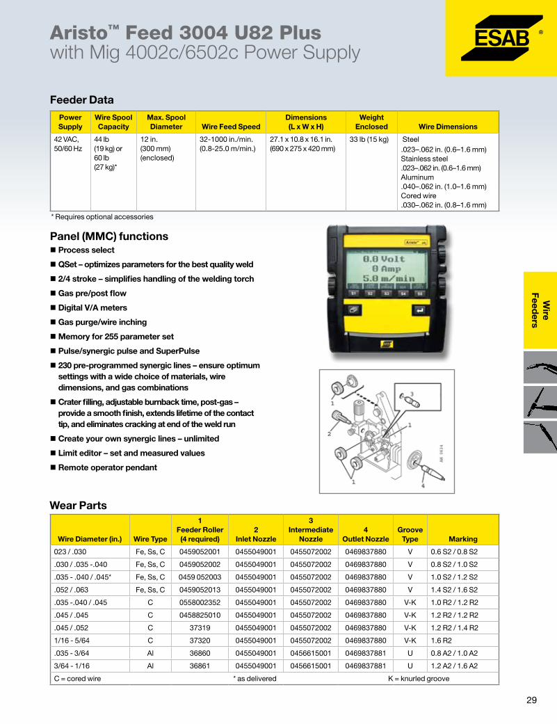
29
Wire
Feeders
Aristo™ Feed 3004 U82 Plus with Mig 4002c/6502c Power Supply
� Process select
� QSet – optimizes parameters for the best quality weld
� 2/4 stroke – simplifies handling of the welding torch
� Gas pre/post flow
� Digital V/A meters
� Gas purge/wire inching
�Memory for 255 parameter set
� Pulse/synergic pulse and SuperPulse
� 230 pre-programmed synergic lines – ensure optimum settings with a wide choice of materials, wire dimensions, and gas combinations
� Crater filling, adjustable burnback time, post-gas – provide a smooth finish, extends lifetime of the contact tip, and eliminates cracking at end of the weld run
� Create your own synergic lines – unlimited
� Limit editor – set and measured values
� Remote operator pendant
Panel (MMC) functions
Wear Parts
* Requires optional accessories
Feeder DataPower Supply
Wire Spool Capacity
Max. Spool Diameter Wire Feed Speed
Dimensions (L x W x H)
Weight Enclosed Wire Dimensions
42 VAC, 50/60 Hz
44 lb (19 kg) or 60 lb (27 kg)*
12 in. (300 mm) (enclosed)
32-1000 in./min. (0.8-25.0 m/min.)
27.1 x 10.8 x 16.1 in. (690 x 275 x 420 mm)
33 lb (15 kg) Steel .023–.062 in. (0.6–1.6 mm) Stainless steel .023–.062 in. (0.6–1.6 mm) Aluminum .040–.062 in. (1.0–1.6 mm) Cored wire .030–.062 in. (0.8–1.6 mm)
Wire Diameter (in.) Wire Type
1 Feeder Roller (4 required)
2 Inlet Nozzle
3 Intermediate
Nozzle4
Outlet NozzleGroove
Type Marking
023 / .030 Fe, Ss, C 0459052001 0455049001 0455072002 0469837880 V 0.6 S2 / 0.8 S2
.030 / .035 -.040 Fe, Ss, C 0459052002 0455049001 0455072002 0469837880 V 0.8 S2 / 1.0 S2
.035 - .040 / .045* Fe, Ss, C 0459 052003 0455049001 0455072002 0469837880 V 1.0 S2 / 1.2 S2
.052 / .063 Fe, Ss, C 0459052013 0455049001 0455072002 0469837880 V 1.4 S2 / 1.6 S2
.035 -.040 / .045 C 0558002352 0455049001 0455072002 0469837880 V-K 1.0 R2 / 1.2 R2
.045 / .045 C 0458825010 0455049001 0455072002 0469837880 V-K 1.2 R2 / 1.2 R2
.045 / .052 C 37319 0455049001 0455072002 0469837880 V-K 1.2 R2 / 1.4 R2
1/16 - 5/64 C 37320 0455049001 0455072002 0469837880 V-K 1.6 R2
.035 - 3/64 Al 36860 0455049001 0456615001 0469837881 U 0.8 A2 / 1.0 A2
3/64 - 1/16 Al 36861 0455049001 0456615001 0469837881 U 1.2 A2 / 1.6 A2
C = cored wire * as delivered K = knurled groove
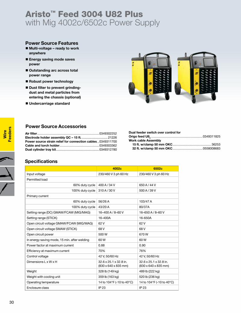
30
Wir
eFe
eder
s
Aristo™ Feed 3004 U82 Plus with Mig 4002c/6502c Power Supply
�Multi-voltage – ready to work anywhere
� Energy saving mode saves power
� Outstanding arc across total power range
� Robust power technology
� Dust filter to prevent grinding-dust and metal particles from entering the chassis (optional)
� Undercarriage standard
Power Source Features
Air filter ........................................................................0349302252Electrode holder assembly QC – 15 ft. .............................. 21226Power source strain relief for connection cables ..0349311700Cable and torch holder ..............................................0349303362Dual cylinder tray kit ..................................................0349312780
Dual feeder switch over control for Origo feed U82 ............................................................0349311825Work cable Assembly 15 ft. w/clamp 50 mm OKC ............................................. 36253 32 ft. w/clamp 50 mm OKC ...................................0558008683
Specifications
Power Source Accessories
4002c 6502c
Input voltage 230/460 V 3 ph 60 Hz 230/460 V 3 ph 60 Hz
Permitted load
60% duty cycle 400 A / 34 V 650 A / 44 V
100% duty cycle 310 A / 30 V 500 A / 39 V
Primary current
60% duty cycle 56/26 A 103/47 A
100% duty cycle 43/20 A 80/37A
Setting range (DC) GMAW/FCAW (MIG/MAG) 16–400 A / 8–60 V 16–650 A / 8–60 V
Setting range (STICK) 16-400A 16-650A
Open circuit voltage GMAW/FCAW (MIG/MAG) 62 V 62 V
Open circuit voltage SMAW (STICK) 68 V 68 V
Open circuit power 500 W 670 W
In energy saving mode, 15 min. after welding 60 W 60 W
Power factor at maximum current 0.88 0.90
Efficiency at maximum current 70% 76%
Control voltage 42 V, 50/60 Hz 42 V, 50/60 Hz
Dimensions L x W x H 32.6 x 25.1 x 32.8 in. (830 x 640 x 835 mm)
32.6 x 25.1 x 32.8 in. (830 x 640 x 835 mm)
Weight 328 lb (149 kg) 489 lb (222 kg)
Weight with cooling unit 359 lb (163 kg) 520 lb (236 kg)
Operating temperature 14 to 104°F (-10 to 40°C) 14 to 104°F (-10 to 40°C)
Enclosure class IP 23 IP 23

31
Wire
Feeders
Product Data Page ...................................................... ARC-23185
If your application demands efficient root runs or positional welding on thin, or thick aluminum or stainless materials, then SuperPulse will provide the optimum solution. With productivity as the objective, today’s TIG process is tomorrow’s Aristo SuperPulse.
The prime advantage of the pulse/pulse process is the ability to control the heat input. Pulse/pulse is a well established process and has mainly been focused on aluminum welding.
Now SuperPulse is a further development of the pulse/pulse concept with the following additional combinations:
Pulse/short arc—Replace the TIG process by welding the root pass with the pulse/short-arc process. This process enables full control of the heat input for any thin sheet welding.
Spray arc/pulse—A very efficient process in positional welding of thicker materials. Aluminum can be welded straight upwards without the usual torch manipulation. (Less tiring for the operator)
MIG brazing of very thin sheets is another application where we recommend Aristo SuperPulse.
New welding processes will always require expert advice and training. To find out more about the process or applications surrounding Aristo SuperPulse please contact your local ESAB sales office for further information.
ESAB has welding process centers located in Hanover (US), Florence (US), Gothenburg (SE), Solingen (DE), Utrecht (NL), Waltham Cross (GB), Milan (IT) and Vamberk (CZ). All are prepared to undertake application trials for you, or offer a complete application/training package.
A complete package consists of:
Aristo Mig or Origo Mig power source Aristo Feed 3004 wire feeder with U8
2 pendant
MIG welding torch
pulse / pulse
pulse / short arc
spray / pulse
Aristo™ SuperPulse™
�Makes positional welding easier
� Allows welding with low heat input
� Provides uniform penetration
� Allows operator more control over welding speed
� TIG-looking weld appearance with MIG
� Very adaptable to all kind of mechanization, for example, Railtrac and Miggytrac
� Extends working range with larger wire size
� Less sensitive to joint gap variations
� Less sensitive to unequal heat transfer

32
Wir
eFe
eder
s
Ordering InformationBalance Boom 8 ft. B-8/FHD .........................................................0558004002 10 ft. B-10/FHD .....................................................0558004006 12 ft. B-12/FHD .....................................................0558003734 16 ft. B-16/FHD .....................................................0558003737
AccessoriesPlastic Trough 8 ft. ..........................................................................0558004004 10 ft. ........................................................................0558004008 12 ft. ........................................................................0558003447 16 ft. ........................................................................0558003732(Troughs neatly contain cables and hoses to feeder)Boom Mounting Bracket Kit DuraDrive Feeder .............................................. 0558003735M Aristo, Origo Feed .................................................0558005581Feeder Strain Relief for Torch ..................................0457341881(Aristo or Origo only, not for DuraDrive)ERS Conduit Bushing Support Bracket ..........................37770(Used with 948259. Holds conduit inlet inline with spool)Spindle Assembly .............................................................948259(For mast mounted spools. Requires 1/4” hardware)Coil Adapter for 60 lb. coils ..................................................34323Pallet Base ...........................................................................37776(Requires anchoring to floor in use)Welding Cart with Wheels ..................................................37777(Use with 12 ft. maximum boom and 300 lb. and heavier power source)Inlet Guide 4-30 mm Marathon ................................0558002354(Accepts QCA Adapter 899F50)See Marathon Pac Conduits to guide wire from Marathon Pacs or mast mounted spindles. Add 4 ft. to boom length to get conduit length for mast mounted spindle. Add at least 7 ft. plus boom length for Marathon Pac payed wire.
Balanced Boom Assembly
� Extended a 12 or 15 ft. torch’s reach from a 20 ft. radius up to a 31 ft. radius
� 350 degree envelope of operation in most uses
� Boom adjusts from 50 degrees up to 6 degrees down from horizontal position, can be used for tall weldments
� Fully balances feeder weight for fingertip control of feeder height, no lever jacking
�Mast has 6 ft. 10 in. clearance from floor to boom support pin
� Standard mounting directly to concrete floor
� Pallet and cart mounting options available
� Extremely rugged steel construction for years of continuous use
�Weld parameters easily adjustable on the standard feeder at the end of boom
�Wire spools mountable to mast or feed wire from Marathon Pac
Product Data Page.................................................... ARC-23213A
Typical Wire Feeder Mounting Bracket
Typical Wire Feeder
AristoFeed, OrigoFeed or DuraDrive Wire Feeder (without reel stand)
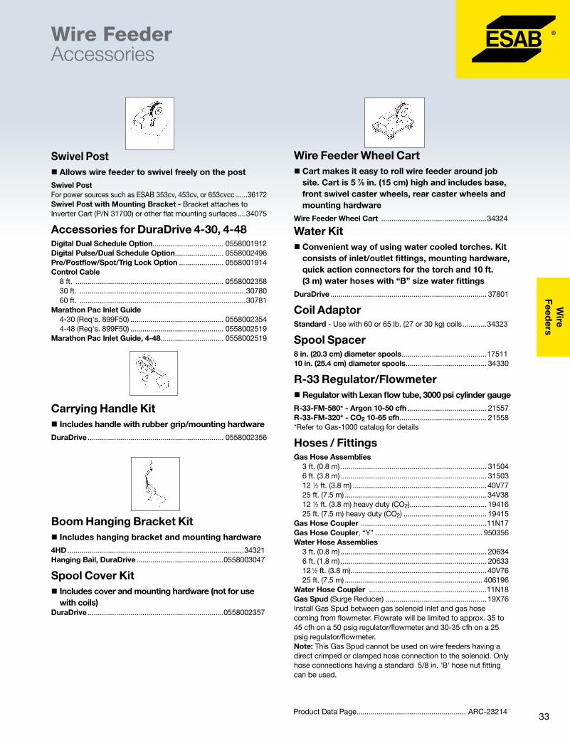
33
Wire
Feeders
Swivel Post � Allows wire feeder to swivel freely on the post
Swivel PostFor power sources such as ESAB 353cv, 453cv, or 653cvcc ......36172Swivel Post with Mounting Bracket - Bracket attaches to Inverter Cart (P/N 31700) or other flat mounting surfaces ....34075
Accessories for DuraDrive 4-30, 4-48Digital Dual Schedule Option................................... 0558001912Digital Pulse/Dual Schedule Option ........................ 0558002496Pre/Postflow/Spot/Trig Lock Option ...................... 0558001914Control Cable 8 ft. ......................................................................... 0558002358 30 ft. ..................................................................................30780 60 ft. ..................................................................................30781Marathon Pac Inlet Guide 4-30 (Req's. 899F50) .............................................. 0558002354 4-48 (Req's. 899F50) .............................................. 0558002519Marathon Pac Inlet Guide, 4-48 ............................... 0558002519
Carrying Handle Kit � Includes handle with rubber grip/mounting hardware
DuraDrive ................................................................... 0558002356
Boom Hanging Bracket Kit � Includes hanging bracket and mounting hardware
4HD .......................................................................................34321Hanging Bail, DuraDrive ...........................................0558003047
Spool Cover Kit � Includes cover and mounting hardware (not for use with coils)
DuraDrive ...................................................................0558002357
Water Kit � Convenient way of using water cooled torches. Kit consists of inlet/outlet fittings, mounting hardware, quick action connectors for the torch and 10 ft. (3 m) water hoses with “B” size water fittings
DuraDrive ............................................................................. 37801
Coil Adaptor Standard - Use with 60 or 65 lb. (27 or 30 kg) coils ............34323
Spool Spacer 8 in. (20.3 cm) diameter spools ..........................................1751110 in. (25.4 cm) diameter spools ........................................ 34330
R-33 Regulator/Flowmeter � Regulator with Lexan flow tube, 3000 psi cylinder gauge
R-33-FM-580* - Argon 10-50 cfh ....................................... 21557R-33-FM-320* - CO2 10-65 cfh........................................... 21558*Refer to Gas-1000 catalog for details
Hoses / FittingsGas Hose Assemblies 3 ft. (0.8 m) ........................................................................ 31504 6 ft. (3.8 m) ........................................................................ 31503 12 1⁄2 ft. (3.8 m) ..................................................................40V77 25 ft. (7.5 m) ......................................................................34V38 12 1⁄2 ft. (3.8 m) heavy duty (CO2)...................................... 19416 25 ft. (7.5 m) heavy duty (CO2) ......................................... 19415Gas Hose Coupler ..............................................................11N17Gas Hose Coupler, “Y” ..................................................... 950356Water Hose Assemblies 3 ft. (0.8 m) ........................................................................ 20634 6 ft. (1.8 m) ........................................................................ 20633 12 1⁄2 ft. (3.8 m) ...................................................................40V76 25 ft. (7.5 m) .................................................................... 406196Water Hose Coupler ..........................................................11N18Gas Spud (Surge Reducer) ..................................................19X76Install Gas Spud between gas solenoid inlet and gas hose coming from flowmeter. Flowrate will be limited to approx. 35 to 45 cfh on a 50 psig regulator/flowmeter and 30-35 cfh on a 25 psig regulator/flowmeter.Note: This Gas Spud cannot be used on wire feeders having a direct crimped or clamped hose connection to the solenoid. Only hose connections having a standard 5/8 in. 'B' hose nut fitting can be used.
Product Data Page...................................................... ARC-23214
Wire FeederAccessories
Wire Feeder Wheel Cart � Cart makes it easy to roll wire feeder around job site. Cart is 5 7⁄8 in. (15 cm) high and includes base, front swivel caster wheels, rear caster wheels and mounting hardware
Wire Feeder Wheel Cart ....................................................34324

34
Wir
eFe
eder
s Ordering InformationSwivel Post for 353/453/460/653 power sources ........... 36172Inverter Cart Fits SVI 450i and 350 mpi ............................31700Swivel Post with bracket (Required with 31700 cart) ........34075Mini-Boom Aristo/Origo Feed Models up to 12" 44 lb. coils ...............................................0458705880 up to 18" 65 lb. coils ...............................................0458705882Required to add mini-boom to power sources shown below: Stabilizer (MIG 320) ................................................0349303475 Reinforcer kit for counterbalance (MIG 410/510) ...0349309748 Stabilizer (MIG 410/510) .........................................0349303474Aristo Swivel Post (Required with no cart) ...............0458731880Aristo Trolley Cart - used when 0458705880 or 0458705882 Mini-Boom is desired has dual feed support also .....0458603880
CounterbalanceMini-Boom
AristoMig power source, AristoMig wire feeder, 25ft. MIG torch, 0458 750 880 Mini-Boom and 0458 603 880 Trolley Cart with 2 gas cylinder capacity shown.
Product Data Page .................................................... ARC-23215
� Up to 25 ft. working radius—effective area of over 1900 sq. ft.
� 350 degree working envelope
�Mounts easily to power source, inverter cart or stationary pedestal
� Lowest cost boom on the market
� Adjustable boom length
� Adjustable counter-balance spring
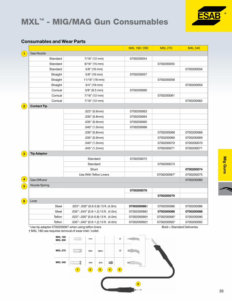
35
Mig
Guns
MXL™ - MIG/MAG Gun Consumables
6
5
4
3
2
1
* Use tip adapter 0700200067 when using teflon liners Bold = Standard Deliveries † MXL 180 use requires removal of wear inlet / collet
MXL 180 / 200 MXL 270 MXL 340
Gas Nozzle
Standard 7/16" (12 mm) 0700200054
Standard 9/16" (15 mm) 0700200055
Standard 5/8" (16 mm) 0700200056
Straight 5/8" (16 mm) 0700200057
Straight 11/16" (18 mm) 0700200058
Straight 3/4" (19 mm) 0700200059
Conical 3/8" (9.5 mm) 0700200060
Conical 7/16" (12 mm) 0700200061
Conical 7/16" (12 mm) 0700200062
Contact Tip
.023" (0.6mm) 0700200063
.030" (0.8mm) 0700200064
.035" (0.9mm) 0700200065
.040" (1.0mm) 0700200066
.030" (0.8mm) 0700200068 0700200068
.035" (0.9mm) 0700200069 0700200069
.040" (1.0mm) 0700200070 0700200070
.045" (1.2mm) 0700200071 0700200071
Tip Adaptor
Standard 0700200072
Standard 0700200073
Short 0700200074
Use With Teflon Liners 0700200067* 0700200075
Gas Diffusor 0700200080
Nozzle Spring
0700200078
0700200079
Liner
Steel .023”-.030” (0.6-0.8) 13 ft. (4.0m) 0700200086† 0700200086 0700200086
Steel .035”-.045” (0.9-1.2) 13 ft. (4.0m) 0700200088† 0700200088 0700200088
Teflon .023”-.030” (0.6-0.8) 13 ft. (4.0m) 0700200090† 0700200090* 0700200090
Teflon .035”-.045” (0.9-1.2) 13 ft. (4.0m) 0700200092† 0700200092* 0700200092
Consumables and Wear Parts
1
6
5432
MXL 180 MXL 200
MXL 270
MXL 340
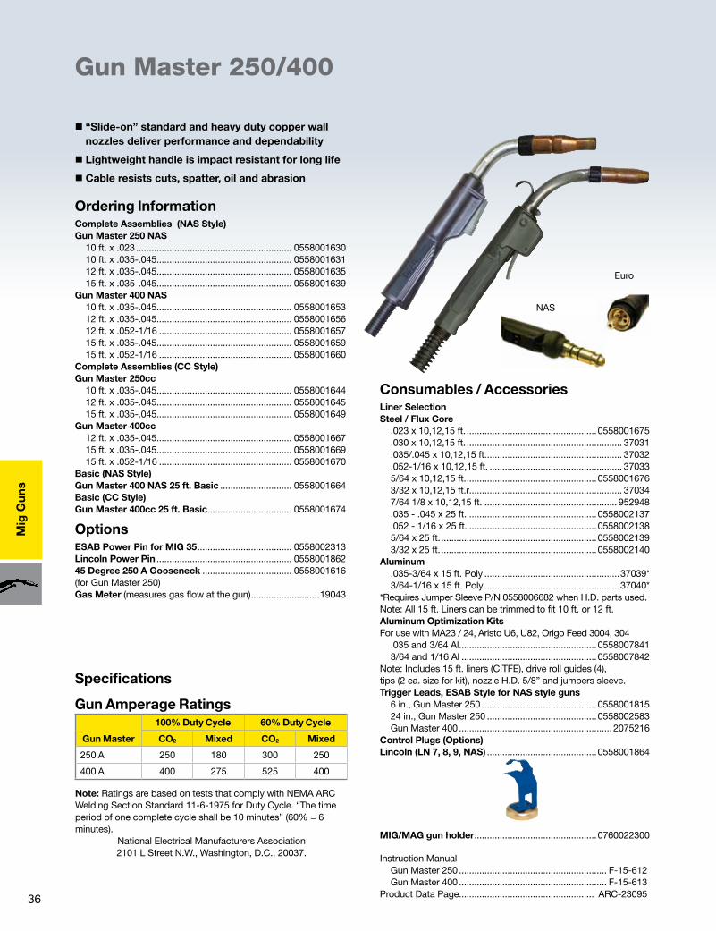
36
Mig
Gun
s
Ordering InformationComplete Assemblies (NAS Style)Gun Master 250 NAS 10 ft. x .023 ............................................................. 0558001630 10 ft. x .035-.045..................................................... 0558001631 12 ft. x .035-.045..................................................... 0558001635 15 ft. x .035-.045..................................................... 0558001639Gun Master 400 NAS 10 ft. x .035-.045..................................................... 0558001653 12 ft. x .035-.045..................................................... 0558001656 12 ft. x .052-1/16 .................................................... 0558001657 15 ft. x .035-.045..................................................... 0558001659 15 ft. x .052-1/16 .................................................... 0558001660Complete Assemblies (CC Style)Gun Master 250cc 10 ft. x .035-.045..................................................... 0558001644 12 ft. x .035-.045..................................................... 0558001645 15 ft. x .035-.045..................................................... 0558001649Gun Master 400cc 12 ft. x .035-.045..................................................... 0558001667 15 ft. x .035-.045..................................................... 0558001669 15 ft. x .052-1/16 .................................................... 0558001670Basic (NAS Style)Gun Master 400 NAS 25 ft. Basic ............................ 0558001664Basic (CC Style)Gun Master 400cc 25 ft. Basic ................................. 0558001674
OptionsESAB Power Pin for MIG 35 ..................................... 0558002313Lincoln Power Pin ..................................................... 055800186245 Degree 250 A Gooseneck ................................... 0558001616(for Gun Master 250)Gas Meter (measures gas flow at the gun) ...........................19043
Gun Master 250/400
Consumables / AccessoriesLiner SelectionSteel / Flux Core .023 x 10,12,15 ft. ...................................................0558001675 .030 x 10,12,15 ft. ............................................................. 37031 .035/.045 x 10,12,15 ft. ..................................................... 37032 .052-1/16 x 10,12,15 ft. .................................................... 37033 5/64 x 10,12,15 ft. ...................................................0558001676 3/32 x 10,12,15 ft.r............................................................ 37034 7/64 1/8 x 10,12,15 ft. .................................................... 952948 .035 - .045 x 25 ft. ..................................................0558002137 .052 - 1/16 x 25 ft. ..................................................0558002138 5/64 x 25 ft. .............................................................0558002139 3/32 x 25 ft. .............................................................0558002140Aluminum .035-3/64 x 15 ft. Poly .....................................................37039* 3/64-1/16 x 15 ft. Poly .....................................................37040**Requires Jumper Sleeve P/N 0558006682 when H.D. parts used.Note: All 15 ft. Liners can be trimmed to fit 10 ft. or 12 ft.Aluminum Optimization Kits For use with MA23 / 24, Aristo U6, U82, Origo Feed 3004, 304 .035 and 3/64 Al ......................................................0558007841 3/64 and 1/16 Al .....................................................0558007842Note: Includes 15 ft. liners (CITFE), drive roll guides (4), tips (2 ea. size for kit), nozzle H.D. 5/8” and jumpers sleeve.Trigger Leads, ESAB Style for NAS style guns 6 in., Gun Master 250 .............................................0558001815 24 in., Gun Master 250 ...........................................0558002583 Gun Master 400 ............................................................ 2075216Control Plugs (Options)Lincoln (LN 7, 8, 9, NAS) ...........................................0558001864
MIG/MAG gun holder ................................................0760022300
Instruction Manual Gun Master 250 .......................................................... F-15-612 Gun Master 400 .......................................................... F-15-613Product Data Page..................................................... ARC-23095
� “Slide-on” standard and heavy duty copper wall nozzles deliver performance and dependability
� Lightweight handle is impact resistant for long life
� Cable resists cuts, spatter, oil and abrasion
Note: Ratings are based on tests that comply with NEMA ARC Welding Section Standard 11-6-1975 for Duty Cycle. “The time period of one complete cycle shall be 10 minutes” (60% = 6 minutes).
National Electrical Manufacturers Association 2101 L Street N.W., Washington, D.C., 20037.
Specifications
Gun Amperage Ratings
Euro
NAS
Gun Master
100% Duty Cycle 60% Duty Cycle
CO2 Mixed CO2 Mixed
250 A 250 180 300 250
400 A 400 275 525 400
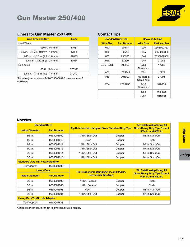
37
Mig
Guns
Gun Master 250/400
Wire Type and Size Liner
Hard Wires
.030 in. (0.8mm) 37031
.035 in. - .045 in. (0.9mm - 1.2mm) 37032
.045 in. - 1/16 in. (1.2 - 1.6mm) 37033
5/64 in. - 3/32 in. (2 - 2.4mm) 37034
Soft Wires
.035 in. (0.9mm) 37039*
3/64 in. - 1/16 in. (1.2 - 1.6mm) 37040*
Liners for Gun Master 250 / 400
*Requires jumper sleeve P/N 0558006682 for aluminum/soft wire liners
Contact TipsStandard Duty Tips Heavy Duty Tips
Wire Size Part Number Wire Size Part Number
.023 20543 .030 0558002367
.030 20544 .035 0558002368
.035 996995 .040 0558002369
.045 37290 .045 37286
.045 - 3/64 996999 3/64 Aluminum
17765
.052 2075349 .052 17778
1/16 996997 1/16 Hard or Cored Wire
37291
5/64 2075230 1/16 Aluminum
948835
5/64 948832
3/32 948833
Standard DutyTip Relationship Using All Sizes Standard Duty Tips
Tip Relationship Using All Sizes Heavy Duty Tips Except
5/64 in. and 3/32 in. Inside Diameter Part Number
3/8 in. 0558001609 1/8 in. Stick Out Copper 1/8 in. Stick Out
1/2 in. 0558001612 Flush Copper Flush
1/2 in. 0558001611 1/8 in. Stick Out Copper 1/8 in. Stick Out
1/2 in. 0558001613 1/4 in. Stick Out Copper 1/4 in. Stick Out
5/8 in. 0558001614 1/8 in. Stick Out Copper 1/8 in. Stick Out
5/8 in. 0558001615 1/4 in. Stick Out Copper 1/4 in. Stick Out
Standard Duty Tip/Nozzle Adaptor
Tip/Adaptor 0558001608
Heavy DutyTip Relationship Using 5/64 in. and 3/32 in.
Heavy Duty Tips Only
Tip Relationship Using All Sizes Heavy Duty Tips Except
5/64 in. and 3/32 in.Inside Diameter Part Number
5/8 in. 0558001599 1/8 in. Recess Copper Flush
5/8 in. 0558001600 1/4 in. Recess Copper Flush
5/8 in. 0558001598 Flush Copper 1/8 in. Stick Out
5/8 in. 0558001601 1/8 in. Stick Out Copper 1/4 in. Stick Out
Heavy Duty Tip/Nozzle Adaptor
Tip/Adaptor 0558001888
All tips are the medium length to give these relationships.
Nozzles

38
Mig
Gun
s
Mig Guns Water-Cooled ST-16/ST-21/ST-21M
� Rated at 600 Amps with any shielding gas
� Handles flux cored wires to 7/64 in.
� ST-21M has an in-line body style designed for mechanized applications
ST-16
ST-21M
Instruction Manuals ST-16 ............................................................................F-11-744 ST-21 ............................................................................F-12-218 ST-21M .........................................................................F-11-964Product Data Page ..................................................... ARC-23218
Ordering InformationThese guns do not include liner/conduits, contact tips/tubes or nozzles. Select the accessories listed in Tables under Mig Gun Accessories to customize a gun that is just right for your job.
ST-16, 10 ft. (3.0 m) ............................................................ 997498ST-21, 12 ft. (3.6 m) ............................................................ 995950ST-21M, 2 ft. (0.6 m) .......................................................... 690509
Options / AccessoriesSpatter Liner ......................................................................633603Centering Bushing ..............................................................17782EH-10A Mech. Gun Mounting Bracket (ST-21M) ..........633885EH-10A Connection Block Assy (ST-21M) ........................58V74ST-16/21 Outlet Adapter for DuraDrives ...............0588000995Power Cable Adaptor ........................................................45V11Gas Meter (measures gas flow at the gun) ......................19043
ST-21
Specifications
ST-16 ST-21 ST-21M
Gun Capacity 600 A, 100% duty cycle 600 A, 100% duty cycle 600 A, 100% duty cycle
Dimensions
Length 13 3/4 in. (350 mm) 12 1/2 in. (315 mm) 10 1/4 in. (260 mm)
Height 4 1/4 in. (110 mm) 7 1/16 in. (180 mm)
Handle Diameter 1 3/8 in. (35 mm) 1 3/8 in. (35 mm) 1 3/8 in. (35 mm)
Gun Angle 55˚ 180˚ 180˚
Weight (less service lines) 28 oz. (794 g) 38 oz. (1077 g) 28 oz. (794 g)
Cooling Requirements (minimum) 1.6 qt./min. (1.5 l/min.) 1.6 qt./min. (1.5 l/min.) 1.6 qt./min. (1.5 l/min.)
Wires Accommodated
Hard .030-3/32 in. (0.8-2.4 mm) .030-3/32 in. (0.8-2.4 mm) .030-3/32 in. (0.8-2.4 mm)
Soft .035-3/32 in. (0.9-2.4 mm) .035-3/32 in. (0.9-2.4 mm) .035-3/32 in. (0.9-2.4 mm)
Cored .030-7/64 in. (0.8-2.8 mm) .030-7/64 in. (0.8-2.8 mm) .030-7/64 in. (0.8-2.8 mm)
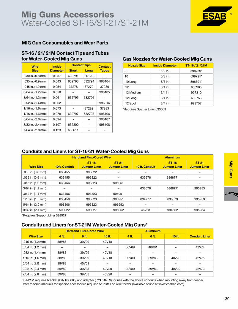
39
Mig
Guns
Mig Guns AccessoriesWater-Cooled ST-16/ST-21/ST-21M
Nozzle Size Inside Diameter ST-16 / 21/21M
8 1/2 in. 598739*
10 5/8 in. 598721*
10 Long 5/8 in. 598891*
12 3/4 in. 633985
12 Medium 3/4 in. 997310
12 Long 3/4 in. 639756
12 Spot 3/4 in. 993757
Wire Size
Inside Diameter
Contact Tips Contact TubesShort Long
.030 in. (0.8 mm) 0.037 632791 20123 –
.035 in. (0.9 mm) 0.043 632793 632794 996104
.045 in. (1.2 mm) 0.054 37278 37279 37280
3/64 in. (1.2 mm) 0.058 – – 996105
3/64 in. (1.2 mm) 0.061 632795 632796 -
.052 in. (1.4 mm) 0.062 – – 996816
1/16 in. (1.6 mm) 0.073 - 37282 37283
1/16 in. (1.6 mm) 0.078 632797 632798 996106
5/64 in. (2.0 mm) 0.094 - – 996107
3/32 in. (2.4 mm) 0.107 632800 – 996108
7/64 in. (2.8 mm) 0.123 633611 – –
MIG Gun Consumables and Wear Parts
Gas Nozzles for Water-Cooled Mig Guns
*Requires Spatter Liner 633603
Hard and Flux-Cored Wire Aluminum
Wire Size 10ft. ConduitST-16
Jumper LinerST-21
Jumper Liner 10 ft. ConduitST-16
Jumper LinerST-21
Jumper Liner
.030 in. (0.8 mm) 633455 993822 – – – –
.035 in. (0.9 mm) 633455 993822 – 633578 636877* –
.045 in. (1.2 mm) 633456 993823 995951 – – –
3/64 in. (1.2 mm) – – – 633578 636877* 995953
.052 in. (1.4 mm) 633456 993823 995951 – – –
1/16 in. (1.6 mm) 633456 993823 995951 634777 636879 995953
5/64 in. (2.0 mm) 598806 993823 995952 – – –
3/32 in. (2.4 mm) 598922 598927 995952 46V68 994552 995954
Conduits and Liners for ST-16/21 Water-Cooled Mig Guns
*Requires Support Liner 598927
Wire Size
Hard and Flux-Cored Wire Aluminum
Conduit Liner4 ft. 6 ft. 10 ft. 4 ft. 6 ft. 10 ft.
.045 in. (1.2 mm) 38V86 39V99 40V18 – – – –
3/64 in. (1.2 mm) – – – 38V89 40V01 – 42V74
.052 in. (1.4 mm) 38V86 39V99 40V18 – – – –
1/16 in. (1.6 mm) 38V86 39V99 40V18 39V80 39V83 40V20 42V75
5/64 in. (2.0 mm) 38V89 40V01 – – – – –
3/32 in. (2.4 mm) 39V80 39V83 40V20 39V80 39V83 40V20 42V73
7/64 in. (2.8 mm) 39V80 39V83 40V20 – – – –
Conduits and Liners for ST-21M Water-Cooled Mig Guns*
* ST-21M requires bracket (P/N 633885) and adaptor (P/N 61N59) for use with the above conduits when mounting away from feeder. Refer to torch manuals for specific accessories required to install on wire feeder (available online at www.esabna.com)
ST-16 / 21/ 21M Contact Tips and Tubes for Water-Cooled Mig Guns
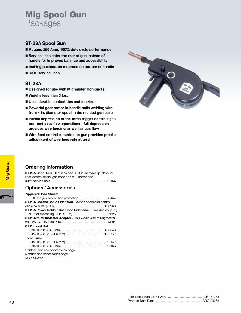
40
Mig
Gun
s
Mig Spool Gun Packages
Ordering InformationST-23A Spool Gun - Includes one 3/64 in. contact tip, drive roll, liner, control cable, gas hose and #10 nozzle and 30 ft. service lines .................................................................19164
Options / AccessoriesZippered Hose Sheath 25 ft. for gun service line protection .................................35454ST-23A Control Cable Extension Extends spool gun control cable by 30 ft. (9.1 m) .........................................................636968ST-23A Power Cable / Gas Hose Extension - Includes coupling 11N19 for extending 30 ft. (9.1 m) ........................................15626ST-23A to MultiMaster Adaptor - This would also fit MigMaster 203, 253's, 215, 280 PRO .....................................................37301ST-23 Feed Roll .030-.035 in. (.8-.9 mm) ..................................................636343 .045-.062 in. (1.2-1.6 mm) ............................................ 996112*Torch Liner .045-.062 in. (1.2-1.6 mm) .............................................. 19167* .030-.035 in. (.8-.9 mm) ....................................................19166Contact Tips see Accessories pageNozzles see Accessories page*As delivered.
Instruction Manual, ST-23A ..............................................F-14-353Product Data Page ...................................................... ARC-23066
ST-23A Spool Gun
ST-23A
� Rugged 250 Amp, 100% duty cycle performance
� Service lines enter the rear of gun instead of handle for improved balance and accessibility
� Inching pushbutton mounted on bottom of handle
� 30 ft. service lines
� Designed for use with Migmaster Compacts
�Weighs less than 3 lbs.
� Uses durable contact tips and nozzles
� Powerful gear motor in handle pulls welding wire from 4 in. diameter spool in the molded gun case
� Partial depression of the torch trigger controls gas pre- and post-flow operations - full depression provides wire feeding as well as gas flow
�Wire feed control mounted on gun provides precise adjustment of wire feed rate at torch

41
Mig
Guns
Ordering InformationMT-250 SG Spool Gun - Includes three 3/64 in. contact tips,drive roll, liner, control cable, gas hose and #10 nozzleand 25 ft. service lines .........................................................36779
Options / AccessoriesMT-250 SGZippered Hose Sheath 25 ft. for gun service line protection .................................35454Gun Extension Lines Gas Hose Assembly, 25 ft. ............................................. 34V38Coupling, Gas Hose (5/8 in. - 18 in.) .................................. 11N17Replacement power hose/gas hose, 25 ft. ............0558002476Quick Connector Male #2 - 1/0 ..............................................................13733936 Female #2 - 1/0 ...........................................................13735632Gas Meter (measures gas flow at the gun) ......................19043Feed Roll .030-3/64 in. Soft wire(.8-1.2 mm) .................. *36866Feed Roll Knurled .030-.045 in. Hard wire(.8-1.2 mm) ....36867Inlet Guide Liner .030-3/64 in. (.8-1.2 mm) Gray ..............36869Barrel Liner .030-3/64 in. (.8-1.2 mm) White .....................36871Contact Tips see Accessories pageNozzles see Accessories page
Instruction Manual, MT-250SG ........................................F-15-380Product Data Page ..................................................... ARC-23211
Mig Spool Gun Packages
� Designed for use with the Migmaster Compacts
�Weighs less than 3 lbs.
� Uses durable MT contact tips and nozzles
� Powerful gear motor in handle pulls welding wire from 4 in. diameter spool in the molded gun case
� Partial depression of the torch trigger controls gas pre- and post-flow operations - full depression provides wire feeding as well as gas flow
�Wire feed control mounted on gun provides precise adjustment of wire feed rate at torch
MT-250 SG Spool Gun
MT-250 SG
�Medium-duty 200 Amp, 100% duty performance
� Spool holder adjusts to balance in the operator’s hand
� 25 ft. service lines

42
Mig
Gun
s
Mig Spool Gun Accessories
ST-23A, MT-250SG Spool Guns
Contact Tips
Wire Size Inside Diameter Short
Contact Tips
**Standard Duty Medium Long
**Heavy Duty Medium
.023 in. (0.6mm) 0.031 – 20543 999742 –
.030 in. (0.8mm) 0.037 – 20544 996994 0558002367
.030 in. (Notched) 0.043 – 36884 – –
.035 in. (0.9mm) 0.043 – 996995 996996 0558002368
.035 in. (Notched) 0.048 – 36885 – –
.040 in. (1.0mm) 0.048 – 37287 37288 0558002369
.045 in. (1.2mm) 0.054 999578 37290 996998 37286
3/64 in. (Notched) 0.060 – 36886† – –
3/64 in. (1.2mm) 0.058 – 996999‡ – 17765
*Requires Tip Adapter 17983**Requires Tip Adapter 17984‡Included with ST-23A†Included with MT-250SG
Size Inside Diameter Standard Duty Heavy Duty
6 3/8 in. (10mm) 998895 –
8 1/2 in. (13mm) 998893 –
8 HD 1/2 in. (13mm) – 999471
10 5/8 in. (16mm) 998894 –
10 HD 5/8 in. (16mm) – 999472**
12 HD 3/4 in. (20mm) – 999473
12 Spot 3/4 in. (20mm) – 999625
Nozzles
** Included with ST-23A and MT-250SG

43
Mig
Guns
Ordering InformationPP36 Plus Gas-CooledGun assemblies include standard neck, 3/64 in. drive roll, liners, HD 8mm contact tip, short tip holder and 5/8 in. nozzle 23 pin control plug (for MA23/24, U6, U8² feeders) stocked180° neck 15 ft. ........................................................................0558101453 25 ft. ........................................................................055810145545° neck 15 ft. ........................................................................0558101454 25 ft. ........................................................................055810145610 pin control plug (for MA6, U6, U8 feeders that use 0558004301 Push-Pull module installed for Python only, sold before 3/11/2011) 180° neck 15 ft. ........................................................................0558101457 25 ft. ........................................................................055810145945° neck 15 ft. ........................................................................0558101458 25 ft. ........................................................................05581014602 pin control plug (for Mig-4HD sold with Mig-41A before 3/8/2011) 180° neck 15 ft. ........................................................................0558101461 25 ft. ........................................................................055810146345° neck 15 ft. ........................................................................0558101462 25 ft. ........................................................................0558101464
� Improved 42 VDC motor for more torque and constant, trouble-free feeding
� Improved drive-roll system for soft or difficult wires
� Improved gas seal for long distance arc shielding
� Air cooled 300A CO², 280A mixed gases, 60% duty cycle
� Optimum torch cooling – high endurance
� Time-saving torch neck replacement utilizes central plug system
� Robust construction for durability and extended torch life
� 3-piece combined cable assembly for better flexibility – especially for long distances
� Options available to use with most ESAB 42 VDC wire feeding systems with wire feed speed control at torch
� Optional 9” extended 180° and 45° swiveling necks for hard to reach joints
Mig Gun PP36 Plus MIG/MAG Torch with wire feed speed control
Shown with standard 180º 6 in. neck
Shown with extended 180º 9 in. neck option
Instruction Manual ..................................................... 0558011520Product Data Page ..................................................... ARC-23291
Shown with standard 45º 6 in. neck
Specifications
Shown with ext. 45° 9in. neck
Shown with extended 45º 9 in. neck option
PP 36
Gun Capacity*
Air-Cooled 300 A, CO2
Mixed Gases 280 A, 60% duty cycle
Dimensions
Length 6 3/8 in. (16.9 cm)
Length (Standard Neck) 6 in. (15.24 cm)
Length (Extended Neck) 9 in. (22.86 cm)
Length (Body and Cable Support) 7 in. (17.8 cm)
Height 7 3/8 in. (187 mm)
Handle Diameter 1 3/8 in. (3.49 cm)
Weight (less service lines) 2.2 lbs. (1 kg)
Water Cooling Requirements .4 gal./min. (1.5 l/min.)
Wires Accommodated
.030 in. (0.8 mm) .035 in. (0.9 mm)
.040 in. (1.0 mm) .045 in. (1.2 mm)
3/64 in. (1.6 mm)
1/16
.062 in.
*Rated using power source with VDE standard volt/amp characteristic (V=14V+0.05xA). When pulse MIG welding, reduce rating by 35%. This applies to any MIG torch.
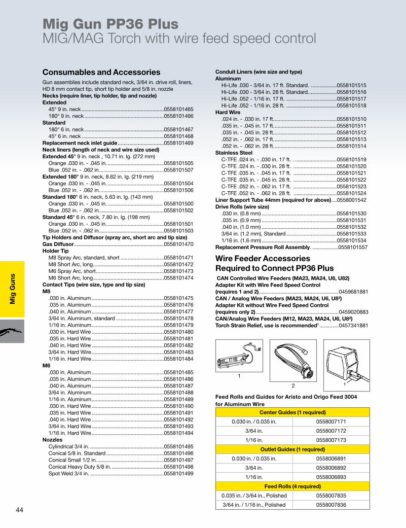
44
Mig
Gun
s
Consumables and AccessoriesGun assemblies include standard neck, 3/64 in. drive roll, liners, HD 8 mm contact tip, short tip holder and 5/8 in. nozzleNecks (require liner, tip holder, tip and nozzle)Extended 45° 9 in. neck .........................................................0558101465 180° 9 in. neck .......................................................0558101466Standard 180° 6 in. neck .......................................................0558101467 45° 6 in. neck .........................................................0558101468Replacement neck inlet guide ................................0558101469Neck liners (length of neck and wire size used)Extended 45° 9 in. neck , 10.71 in. lg. (272 mm) Orange .030 in. - .045 in. .......................................0558101505 Blue .052 in. - .062 in. ............................................0558101507Extended 180° 9 in. neck, 8.62 in. lg. (219 mm) Orange .030 in. - .045 in. .......................................0558101504 Blue .052 in. - .062 in. ............................................0558101506Standard 180° 6 in. neck, 5.63 in. lg. (143 mm) Orange .030 in. - .045 in. ...................................... 0558101500 Blue .052 in. - .062 in. ............................................0558101502Standard 45° 6 in. neck, 7.80 in. lg. (198 mm) Orange .030 in. - .045 in. .......................................0558101501 Blue .052 in. - .062 in. ............................................0558101503Tip Holders and Diffusor (spray arc, short arc and tip size)Gas Diffusor ..............................................................0558101470Holder Tip M8 Spray Arc, standard, short ..............................0558101471 M8 Short Arc, long .................................................0558101472 M6 Spray Arc, short ...............................................0558101473 M6 Short Arc, long .................................................0558101474Contact Tips (wire size, type and tip size)M8 .030 in. Aluminum ..................................................0558101475 .035 in. Aluminum ..................................................0558101476 .040 in. Aluminum ..................................................0558101477 3/64 in. Aluminum, standard .................................0558101478 1/16 in. Aluminum ..................................................0558101479 .030 in. Hard Wire ..................................................0558101480 .035 in. Hard Wire ..................................................0558101481 .040 in. Hard Wire ..................................................0558101482 3/64 in. Hard Wire ..................................................0558101483 1/16 in. Hard Wire ..................................................0558101484M6 .030 in. Aluminum ..................................................0558101485 .035 in. Aluminum ..................................................0558101486 .040 in. Aluminum ..................................................0558101487 3/64 in. Aluminum ..................................................0558101488 1/16 in. Aluminum ..................................................0558101489 .030 in. Hard Wire ..................................................0558101490 .035 in. Hard Wire ..................................................0558101491 .040 in. Hard Wire ..................................................0558101492 3/64 in. Hard Wire ..................................................0558101493 1/16 in. Hard Wire ..................................................0558101494Nozzles Cylindrical 3/4 in. ...................................................0558101495 Conical 5/8 in. Standard ........................................0558101496 Conical Small 1/2 in. ..............................................0558101497 Conical Heavy Duty 5/8 in. ....................................0558101498 Spot Weld 3/4 in. ...................................................0558101499
Conduit Liners (wire size and type)Aluminum Hi-Life .030 - 3/64 in. 17 ft. Standard. ..................0558101515 Hi-Life .030 - 3/64 in. 28 ft. Standard. ...................0558101516 Hi-Life .052 - 1/16 in. 17 ft. ...................................0558101517 Hi-Life .052 - 1/16 in. 28 ft. ...................................0558101518Hard Wire .024 in. - .030 in. 17 ft. ...........................................0558101510 .035 in. - .045 in. 17 ft. ...........................................0558101511 .035 in. - .045 in. 28 ft. ...........................................0558101512 .052 in. - .062 in. 17 ft. ...........................................0558101513 .052 in. - .062 in. 28 ft. ...........................................0558101514Stainless Steel C-TFE .024 in. - .030 in. 17 ft. . .............................0558101519 C-TFE .024 in. - .030 in. 28 ft. ..............................0558101520 C-TFE .035 in. - .045 in. 17 ft. ..............................0558101521 C-TFE .035 in. - .045 in. 28 ft. ..............................0558101522 C-TFE .052 in. - .062 in. 17 ft. ..............................0558101523 C-TFE .052 in. - .062 in. 28 ft. ..............................0558101524Liner Support Tube 44mm (required for above)....0558001542Drive Rolls (wire size) .030 in. (0.8 mm) ....................................................0558101530 .035 in. (0.9 mm) ....................................................0558101531 .040 in. (1.0 mm) ....................................................0558101532 3/64 in. (1.2 mm), Standard ...................................0558101533 1/16 in. (1.6 mm) ....................................................0558101534Replacement Pressure Roll Assembly. ..................0558101557
Wire Feeder Accessories Required to Connect PP36 Plus CAN Controlled Wire Feeders (MA23, MA24, U6, U82)Adapter Kit with Wire Feed Speed Control (requires 1 and 2) .......................................................0459681881CAN / Analog Wire Feeders (MA23, MA24, U6, U8²)Adapter Kit without Wire Feed Speed Control (requires only 2) .........................................................0459020883CAN/Analog Wire Feeders (M12, MA23, MA24, U6, U8²)Torch Strain Relief, use is recommended1 .............0457341881
Mig Gun PP36 Plus MIG/MAG Torch with wire feed speed control
Feed Rolls and Guides for Aristo and Origo Feed 3004 for Aluminum Wire
1
2
Center Guides (1 required)
0.030 in. / 0.035 in. 0558007171
3/64 in. 0558007172
1/16 in. 0558007173
Outlet Guides (1 required)
0.030 in. / 0.035 in. 0558006891
3/64 in. 0558006892
1/16 in. 0558006893
Feed Rolls (4 required)
0.035 in. / 3/64 in., Polished 0558007835
3/64 in. / 1/16 in., Polished 0558007836
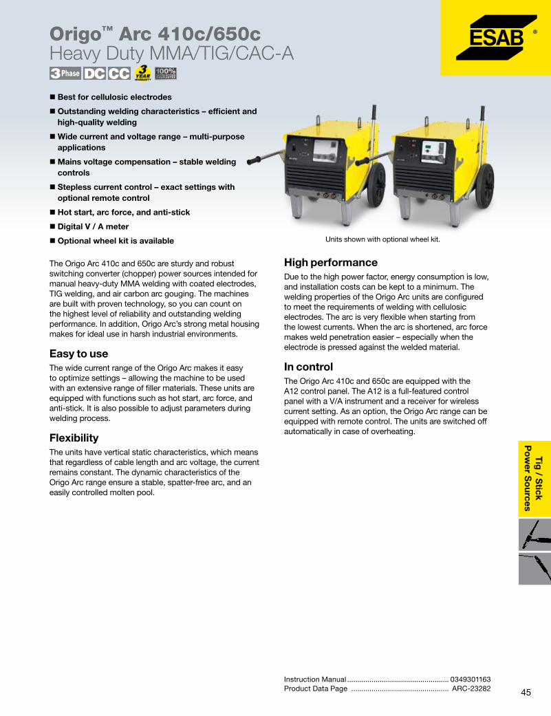
45
Tig
/ Stick
Po
wer S
ources
Mig Gun PP36 Plus MIG/MAG Torch with wire feed speed control
Origo™ Arc 410c/650cHeavy Duty MMA/TIG/CAC-A
The Origo Arc 410c and 650c are sturdy and robust switching converter (chopper) power sources intended for manual heavy-duty MMA welding with coated electrodes, TIG welding, and air carbon arc gouging. The machines are built with proven technology, so you can count on the highest level of reliability and outstanding welding performance. In addition, Origo Arc’s strong metal housing makes for ideal use in harsh industrial environments.
Easy to useThe wide current range of the Origo Arc makes it easy to optimize settings – allowing the machine to be used with an extensive range of filler materials. These units are equipped with functions such as hot start, arc force, and anti-stick. It is also possible to adjust parameters during welding process.
FlexibilityThe units have vertical static characteristics, which means that regardless of cable length and arc voltage, the current remains constant. The dynamic characteristics of the Origo Arc range ensure a stable, spatter-free arc, and an easily controlled molten pool.
� Best for cellulosic electrodes
� Outstanding welding characteristics – efficient and high-quality welding
�Wide current and voltage range – multi-purpose applications
�Mains voltage compensation – stable welding controls
� Stepless current control – exact settings with optional remote control
� Hot start, arc force, and anti-stick
� Digital V / A meter
� Optional wheel kit is available
High performanceDue to the high power factor, energy consumption is low, and installation costs can be kept to a minimum. The welding properties of the Origo Arc units are configured to meet the requirements of welding with cellulosic electrodes. The arc is very flexible when starting from the lowest currents. When the arc is shortened, arc force makes weld penetration easier – especially when the electrode is pressed against the welded material.
In controlThe Origo Arc 410c and 650c are equipped with the A12 control panel. The A12 is a full-featured control panel with a V/A instrument and a receiver for wireless current setting. As an option, the Origo Arc range can be equipped with remote control. The units are switched off automatically in case of overheating.
Instruction Manual .................................................. 0349301163Product Data Page ................................................ ARC-23282
Units shown with optional wheel kit.
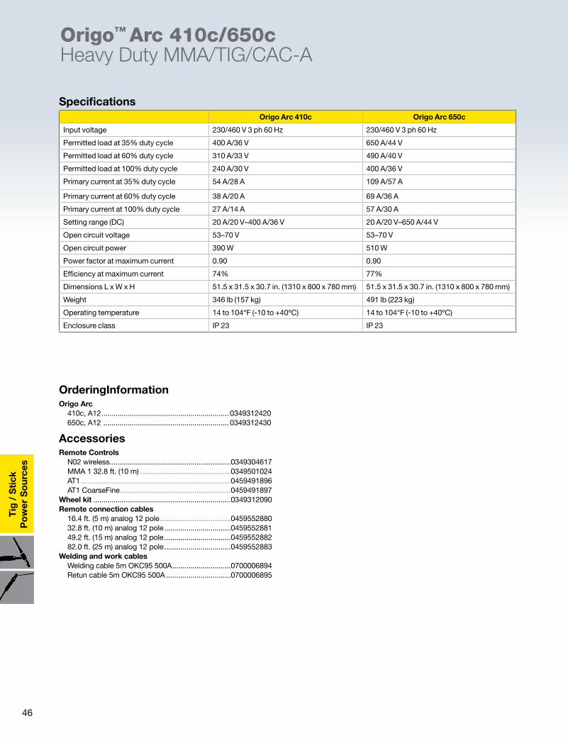
46
Tig
/ S
tick
Po
wer
So
urce
s
OrderingInformationOrigo Arc 410c, A12 ............................................................... 0349312420 650c, A12 .............................................................. 0349312430
AccessoriesRemote Controls N02 wireless............................................................0349304617 MMA 1 32.8 ft. (10 m) .............................................0349501024 AT1 ..........................................................................0459491896 AT1 CoarseFine.......................................................0459491897Wheel kit ....................................................................0349312090Remote connection cables 16.4 ft. (5 m) analog 12 pole ...................................0459552880 32.8 ft. (10 m) analog 12 pole .................................0459552881 49.2 ft. (15 m) analog 12 pole .................................0459552882 82.0 ft. (25 m) analog 12 pole .................................0459552883Welding and work cables Welding cable 5m OKC95 500A .............................0700006894 Retun cable 5m OKC95 500A ................................0700006895
Origo™ Arc 410c/650cHeavy Duty MMA/TIG/CAC-A
SpecificationsOrigo Arc 410c Origo Arc 650c
Input voltage 230/460 V 3 ph 60 Hz 230/460 V 3 ph 60 Hz
Permitted load at 35% duty cycle 400 A/36 V 650 A/44 V
Permitted load at 60% duty cycle 310 A/33 V 490 A/40 V
Permitted load at 100% duty cycle 240 A/30 V 400 A/36 V
Primary current at 35% duty cycle 54 A/28 A 109 A/57 A
Primary current at 60% duty cycle 38 A/20 A 69 A/36 A
Primary current at 100% duty cycle 27 A/14 A 57 A/30 A
Setting range (DC) 20 A/20 V–400 A/36 V 20 A/20 V–650 A/44 V
Open circuit voltage 53–70 V 53–70 V
Open circuit power 390 W 510 W
Power factor at maximum current 0.90 0.90
Efficiency at maximum current 74% 77%
Dimensions L x W x H 51.5 x 31.5 x 30.7 in. (1310 x 800 x 780 mm) 51.5 x 31.5 x 30.7 in. (1310 x 800 x 780 mm)
Weight 346 lb (157 kg) 491 lb (223 kg)
Operating temperature 14 to 104°F (-10 to +40ºC) 14 to 104°F (-10 to +40ºC)
Enclosure class IP 23 IP 23
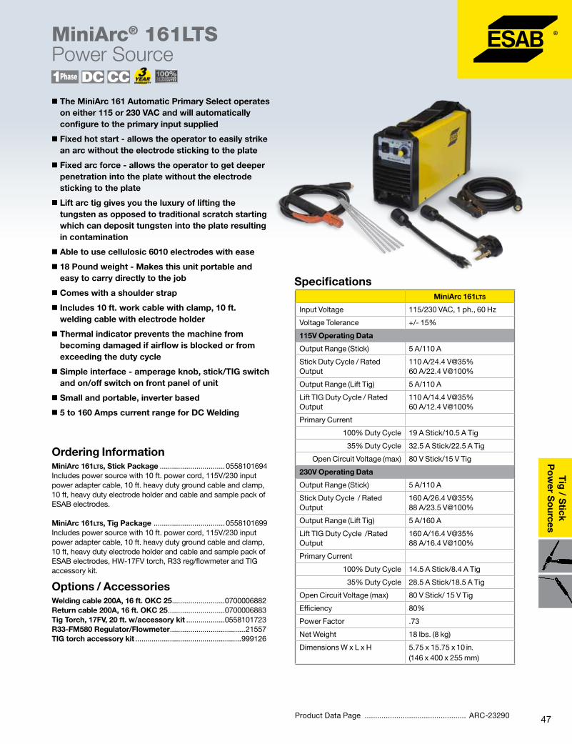
47
Tig
/ Stick
Po
wer S
ources
MiniArc® 161LTSPower Source
Ordering InformationMiniArc 161LTS, Stick Package ................................0558101694Includes power source with 10 ft. power cord, 115V/230 input power adapter cable, 10 ft. heavy duty ground cable and clamp, 10 ft, heavy duty electrode holder and cable and sample pack of ESAB electrodes.
MiniArc 161LTS, Tig Package ...................................0558101699Includes power source with 10 ft. power cord, 115V/230 input power adapter cable, 10 ft. heavy duty ground cable and clamp, 10 ft, heavy duty electrode holder and cable and sample pack of ESAB electrodes, HW-17FV torch, R33 reg/flowmeter and TIG accessory kit.
Options / AccessoriesWelding cable 200A, 16 ft. OKC 25 ..........................0700006882Return cable 200A, 16 ft. OKC 25 ............................0700006883Tig Torch, 17FV, 20 ft. w/accessory kit ...................0558101723R33-FM580 Regulator/Flowmeter .....................................21557TIG torch accessory kit ....................................................999126
� The MiniArc 161 Automatic Primary Select operates on either 115 or 230 VAC and will automatically configure to the primary input supplied
� Fixed hot start - allows the operator to easily strike an arc without the electrode sticking to the plate
� Fixed arc force - allows the operator to get deeper penetration into the plate without the electrode sticking to the plate
� Lift arc tig gives you the luxury of lifting the tungsten as opposed to traditional scratch starting which can deposit tungsten into the plate resulting in contamination
� Able to use cellulosic 6010 electrodes with ease
� 18 Pound weight - Makes this unit portable and easy to carry directly to the job
� Comes with a shoulder strap
� Includes 10 ft. work cable with clamp, 10 ft. welding cable with electrode holder
� Thermal indicator prevents the machine from becoming damaged if airflow is blocked or from exceeding the duty cycle
� Simple interface - amperage knob, stick/TIG switch and on/off switch on front panel of unit
� Small and portable, inverter based
� 5 to 160 Amps current range for DC Welding
Specifications
Product Data Page ................................................ ARC-23290
MiniArc 161LTS
Input Voltage 115/230 VAC, 1 ph., 60 Hz
Voltage Tolerance +/- 15%
115V Operating Data
Output Range (Stick) 5 A/110 A
Stick Duty Cycle / Rated Output
110 A/24.4 V@35% 60 A/22.4 V@100%
Output Range (Lift Tig) 5 A/110 A
Lift TIG Duty Cycle / Rated Output
110 A/14.4 V@35% 60 A/12.4 V@100%
Primary Current
100% Duty Cycle 19 A Stick/10.5 A Tig
35% Duty Cycle 32.5 A Stick/22.5 A Tig
Open Circuit Voltage (max) 80 V Stick/15 V Tig
230V Operating Data
Output Range (Stick) 5 A/110 A
Stick Duty Cycle / Rated Output
160 A/26.4 V@35% 88 A/23.5 V@100%
Output Range (Lift Tig) 5 A/160 A
Lift TIG Duty Cycle /Rated Output
160 A/16.4 V@35% 88 A/16.4 V@100%
Primary Current
100% Duty Cycle 14.5 A Stick/8.4 A Tig
35% Duty Cycle 28.5 A Stick/18.5 A Tig
Open Circuit Voltage (max) 80 V Stick/ 15 V Tig
Efficiency 80%
Power Factor .73
Net Weight 18 lbs. (8 kg)
Dimensions W x L x H 5.75 x 15.75 x 10 in. (146 x 400 x 255 mm)
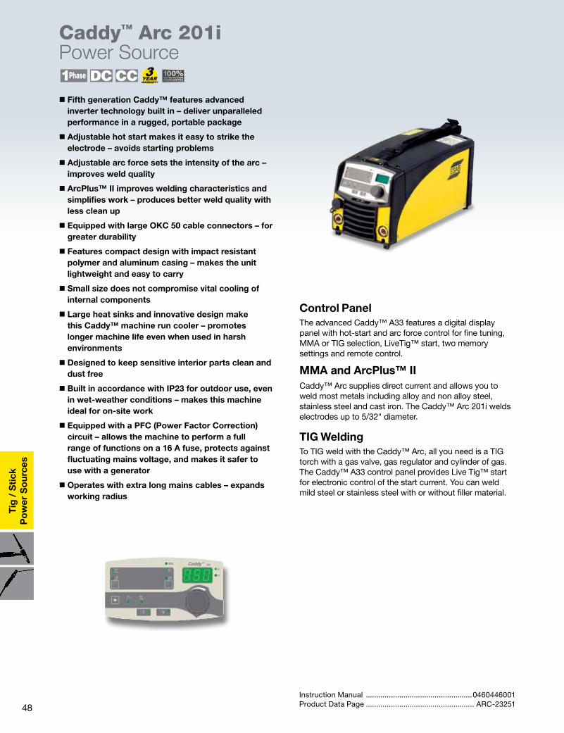
48
Tig
/ S
tick
Po
wer
So
urce
s
� Fifth generation Caddy™ features advanced inverter technology built in – deliver unparalleled performance in a rugged, portable package
� Adjustable hot start makes it easy to strike the electrode – avoids starting problems
� Adjustable arc force sets the intensity of the arc – improves weld quality
� ArcPlus™ II improves welding characteristics and simplifies work – produces better weld quality with less clean up
� Equipped with large OKC 50 cable connectors – for greater durability
� Features compact design with impact resistant polymer and aluminum casing – makes the unit lightweight and easy to carry
� Small size does not compromise vital cooling of internal components
� Large heat sinks and innovative design make this Caddy™ machine run cooler – promotes longer machine life even when used in harsh environments
� Designed to keep sensitive interior parts clean and dust free
� Built in accordance with IP23 for outdoor use, even in wet-weather conditions – makes this machine ideal for on-site work
� Equipped with a PFC (Power Factor Correction) circuit – allows the machine to perform a full range of functions on a 16 A fuse, protects against fluctuating mains voltage, and makes it safer to use with a generator
� Operates with extra long mains cables – expands working radius
Control PanelThe advanced Caddy™ A33 features a digital display panel with hot-start and arc force control for fine tuning, MMA or TIG selection, LiveTig™ start, two memory settings and remote control.
MMA and ArcPlus™ IICaddy™ Arc supplies direct current and allows you to weld most metals including alloy and non alloy steel, stainless steel and cast iron. The Caddy™ Arc 201i welds electrodes up to 5/32" diameter.
TIG WeldingTo TIG weld with the Caddy™ Arc, all you need is a TIG torch with a gas valve, gas regulator and cylinder of gas. The Caddy™ A33 control panel provides Live Tig™ start for electronic control of the start current. You can weld mild steel or stainless steel with or without filler material.
Instruction Manual ...................................................0460446001Product Data Page .................................................... ARC-23251
Caddy™ Arc 201i Power Source
49
Tig
/ Stick
Po
wer S
ources
Ordering InformationCaddy™ Arc 201i, A 33 package ............................ 0460445884Packages include 10 ft. (3m) MMA welding and return cable kit with “screw” type electrode holder
OptionsShoulder Strap ……………………………………….. 04602650032 Wheel Trolley Small gas bottle .................................................... 0459366885 Gas bottle on side.................................................. 0460330880Remote Controls MMA 1, 33 ft. (10 m) cable .................................... 0349501024 AT 1 ........................................................................ 0459491896 AT1 CoarseFine...................................................... 0459491897
Connection cables for AT1 and AT1 CoarseFine 16.5 ft. (5 m) cable ................................................. 0459552880 33 ft. (10 m) cable ................................................. 0459552881 49 ft. (15 m) cable .................................................. 0459552882 82 ft. (25 m) cable .................................................. 0459552883Remote Foot Control* 25 ft. cable ............................................................. 0558008905TIG torch TXH™ OKC50 150V, 13 ft. (4 m) ................................................... 0460011843 150V, 26 ft. (8 m) .................................................... 0460011883 200V, 13 ft. (4 m) .................................................... 0460012841 200V, 26 ft. (8 m) .................................................... 0460012881TIG torch Remote 25 ft.*.......................................... 0558008904* Remotes for use with A33 models only.
Caddy™ Arc 201i Power Source
SpecificationsCaddy™ Arc 201i
Input Voltage 230/1ph 50/60 Hz
Fuse (slow), A 16
Recommended generator size, kVA 12
Permitted load at 104°F (40°C), MMA
25% duty cycle, A/V 170/26.8
60% duty cycle, A/V 130/25.2
100% duty cycle A/V 110/24.4
Permitted load at 104°F (40°C), TIG
25% duty cycle, A/V 220/18.8
60% duty cycle, A/V 150/16.0
100% duty cycle A/V 140/15.6
Setting range MMA (A33), A 4-170
Setting range TIG (A33), A 3-220
Open circuit voltage (A33), V 72
Power factor at max. current 0.99
Efficiency at max. current 81
Dimensions L x W x H 16.46 x 7.40 x 8.19 in. (418 x 188 x 208 mm)
Weight 18.30 lbs (8.3 kg)
Enclosure class IP 23
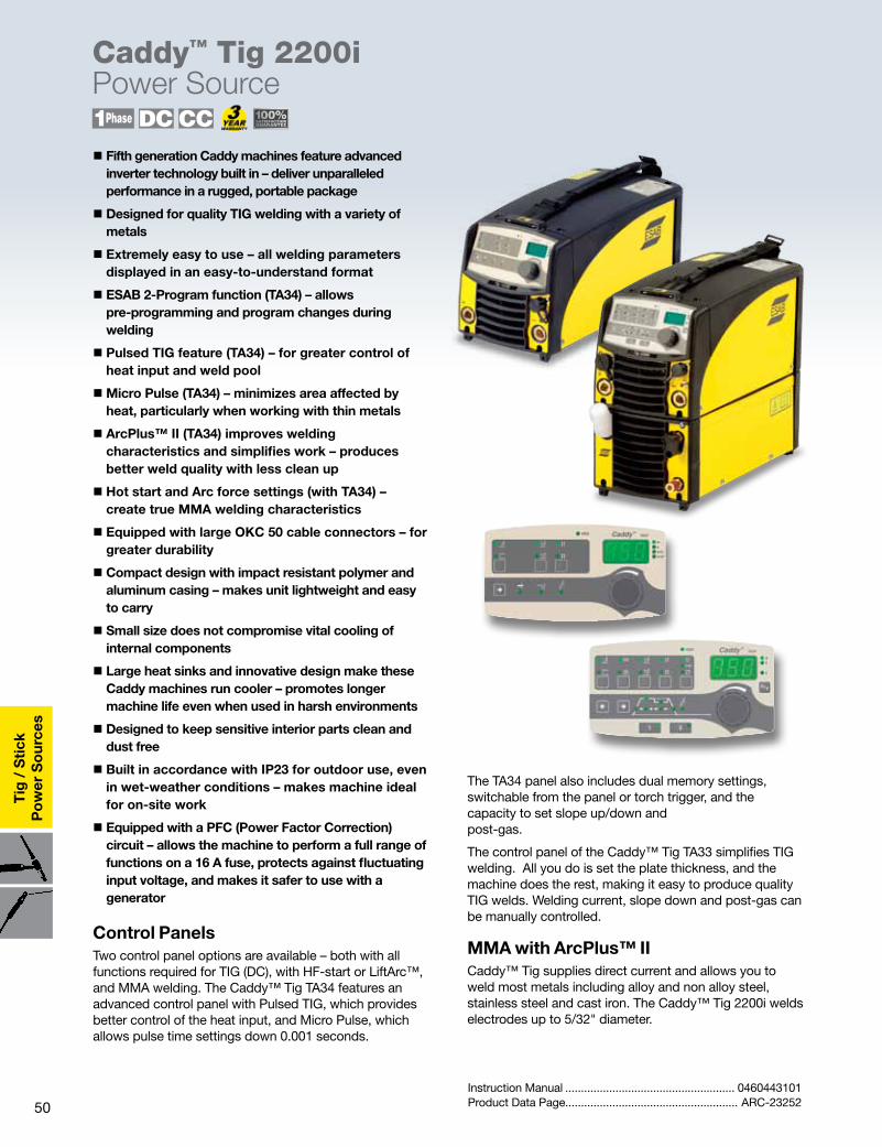
50
Tig
/ S
tick
Po
wer
So
urce
sCaddy™ Tig 2200i Power Source
� Fifth generation Caddy machines feature advanced inverter technology built in – deliver unparalleled performance in a rugged, portable package
� Designed for quality TIG welding with a variety of metals
� Extremely easy to use – all welding parameters displayed in an easy-to-understand format
� ESAB 2-Program function (TA34) – allows pre-programming and program changes during welding
� Pulsed TIG feature (TA34) – for greater control of heat input and weld pool
�Micro Pulse (TA34) – minimizes area affected by heat, particularly when working with thin metals
� ArcPlus™ II (TA34) improves welding characteristics and simplifies work – produces better weld quality with less clean up
� Hot start and Arc force settings (with TA34) – create true MMA welding characteristics
� Equipped with large OKC 50 cable connectors – for greater durability
� Compact design with impact resistant polymer and aluminum casing – makes unit lightweight and easy to carry
� Small size does not compromise vital cooling of internal components
� Large heat sinks and innovative design make these Caddy machines run cooler – promotes longer machine life even when used in harsh environments
� Designed to keep sensitive interior parts clean and dust free
� Built in accordance with IP23 for outdoor use, even in wet-weather conditions – makes machine ideal for on-site work
� Equipped with a PFC (Power Factor Correction) circuit – allows the machine to perform a full range of functions on a 16 A fuse, protects against fluctuating input voltage, and makes it safer to use with a generator
Control PanelsTwo control panel options are available – both with all functions required for TIG (DC), with HF-start or LiftArc™, and MMA welding. The Caddy™ Tig TA34 features an advanced control panel with Pulsed TIG, which provides better control of the heat input, and Micro Pulse, which allows pulse time settings down 0.001 seconds.
Instruction Manual ...................................................... 0460443101Product Data Page....................................................... ARC-23252
The TA34 panel also includes dual memory settings, switchable from the panel or torch trigger, and the capacity to set slope up/down and post-gas.
The control panel of the Caddy™ Tig TA33 simplifies TIG welding. All you do is set the plate thickness, and the machine does the rest, making it easy to produce quality TIG welds. Welding current, slope down and post-gas can be manually controlled.
MMA with ArcPlus™ IICaddy™ Tig supplies direct current and allows you to weld most metals including alloy and non alloy steel, stainless steel and cast iron. The Caddy™ Tig 2200i welds electrodes up to 5/32" diameter.

51
Tig
/ Stick
Po
wer S
ources
Ordering InformationCaddy™ Tig 2200i, TA34 package with TXH™ 200 13 ft. (4 m) TIG torch .................................................0460450883Packages include 10 ft. (3 m) of mains cable, no plug, 5 ft. (1.5 m) of gas hose with 2 hose clamps, 10 ft. (3m) return cable with work clamp and a 10 ft. MMA cable.
To complete a ready-to-weld package, order from the following:R33-FM-580-HB .........................................................0558005172Choose one accessory kit to match the TXH torch:Accessory Kit TXH150 ........................................................................... 999126 TXH200 ........................................................................... 999126 TXH250 ........................................................................... 999127
OptionsShoulder Strap ..........................................................04602650032 Wheel Trolley Small gas bottle .....................................................0459366885 Gas bottle on side...................................................0460330880Remote Controls AT 1 CAN ...............................................................0459491883 AT1 CoarseFine CAN ..............................................0459491884 MTA1 CAN .............................................................0459491880Foot Pedal T1 CAN, with 16.5 ft. (5m) cable ...........0460315880Connection cables for Remote Controls 16.5 ft. (5 m) CAN ...................................................0459554880 33 ft. (10 m) CAN ................................................... 0459554881 49 ft. (15 m) CAN ....................................................0459554882 82 ft. (25 m) CAN ....................................................0459554883TIG Torches TXH™ OKC50 200, 13 ft. (4m) .......................................................0460012840 200f, 13 ft. (4m) ......................................................0460012842 200r, 13 ft. (4m)* .....................................................0462012840 200fr, 13 ft. (4m)* ....................................................0462012842Remote Adapter Kit, (required for*) Includes holder for remote models ..........................0459491912
TIG torch holder .......................................................0760022400
Caddy™ Tig 2200i Power Source
Specifications
Control PanelsTA34 TA33
Slope up, sec 0-10 0-9.9*
Slope down, sec 0-10 0-10
Gas pre-flow*, sec 0-5 0-5
Gas post-flow, sec 0-25 0-25
Pulse, background time, sec
0.01-2.5 -
MicroPulse* time, sec 0.001-0.250 -
Frequency AC, Hz 10-152 65
AC balance, % 50-98 70
Plate thickness setting -(0.1 – 7.3mm) (0.004-0.287in.)
*Hidden functions
Caddy™ Tig 2200i
Input Voltage 230/1 ph. 50/60Hz
Fuse (slow), A 16
Recommended generator size, kVA
12
Permitted load at 40°C (104°F), TIG
25% duty cycle, A/V 220/18.8
60% duty cycle, A/V 150/16
100% duty cycle A/V 110/14.4
Permitted load at 40°C (104°F), MMA
25% duty cycle, A/V 170/26.8
60% duty cycle, A/V 130/25.2
100% duty cycle A/V 110/24.4
Setting range TIG (DC), A 3-220
Setting range MMA (DC), A 4-170
Open circuit voltage, V 72 V
Power factor at max. current (TIG)
0.99
Power factor at max. current (MMA)
0.99
Efficiency at max. current (TIG) 75%
Efficiency at max. current (MMA)
81%
Dimensions L x W x H 16.46 x 7.40 x 8.19 in. (418 x 188 x 208 mm)
Weight 20.72 lbs (9.4kg)
Enclosure class IP23
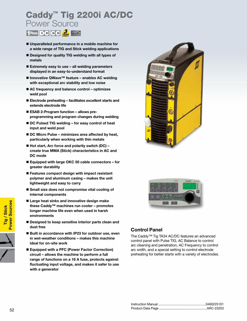
52
Tig
/ S
tick
Po
wer
So
urce
s
Caddy™ Tig 2200i AC/DCPower Source
� Unparalleled performance in a mobile machine for a wide range of TIG and Stick welding applications
� Designed for quality TIG welding with all types of metals
� Extremely easy to use – all welding parameters displayed in an easy-to-understand format
� Innovative QWave™ feature – enables AC welding with exceptional arc stability and low noise
� AC frequency and balance control – optimizes weld pool
� Electrode preheating – facilitates excellent starts and extends electrode life
� ESAB 2-Program function – allows pre-programming and program changes during welding
� DC Pulsed TIG welding – for easy control of heat input and weld pool
� DC Micro Pulse – minimizes area affected by heat, particularly when working with thin metals
� Hot start, Arc force and polarity switch (DC) – create true MMA (Stick) characteristics in AC and DC mode
� Equipped with large OKC 50 cable connectors – for greater durability
� Features compact design with impact resistant polymer and aluminum casing – makes the unit lightweight and easy to carry
� Small size does not compromise vital cooling of internal components
� Large heat sinks and innovative design make these Caddy™ machines run cooler – promotes longer machine life even when used in harsh environments
� Designed to keep sensitive interior parts clean and dust free
� Built in accordance with IP23 for outdoor use, even in wet-weather conditions – makes this machine ideal for on-site work
� Equipped with a PFC (Power Factor Correction) circuit – allows the machine to perform a full range of functions on a 16 A fuse, protects against fluctuating input voltage, and makes it safer to use with a generator
Control PanelThe Caddy™ Tig TA34 AC/DC features an advanced control panel with Pulse TIG, AC Balance to control arc cleaning and penetration, AC Frequency to control arc width, and a special setting to control electrode preheating for better starts with a variety of electrodes.
Instruction Manual ......................................................0460225101Product Data Page ......................................................ARC-23253
53
Tig
/ Stick
Po
wer S
ources
Caddy™ Tig 2200i AC/DCPower Source
Ordering InformationCaddy™ Tig 2200i AC/DC, TA34 AC/DC TXH™ 200 13 ft. Torch, 10ft. MMA Kit ....................0460150883Caddy™ Tig 2200iw AC/DC, TA34 AC/DC TXH™ 250w 13 ft., CoolMini water cooler (includes 2 wheel trolley) 10ft. MMA Kit ............................................................. 0460150884Packages include 10 ft. (3 m) of mains cable, no plug, 5 ft. (1.5 m) of gas hose with 2 hose clamps, 10 ft. (3 m) return cable with work clamp.To complete a ready-to-weld package, order from the following:R33-FM-580-HB ........................................................0558005172Choose one accessory kit to match the TXH torch:Accessory Kit TXH200 ........................................................................... 999126 TXH250 ........................................................................... 999127
OptionsCoolMini cooling unit ............................................... 04601448802 Wheel Trolley Small gas bottle ........................................................ 0459366885 Gas bottle on side ................................................... 0460330880Remote Controls AT 1 CAN .................................................................. 0459491883 AT1 CoarseFine CAN ................................................ 0459491884 MTA1 CAN ............................................................... 0459491880 T1 Foot CAN ............................................................. 0460315880Connection cables for Remote Controls 16.5 ft. (5 m) CAN ..................................................... 0459554880 33 ft. (10 m) CAN ...................................................... 0459554881 49 ft. (15 m) CAN ..................................................... 0459554882 82 ft. (25 m) CAN ...................................................... 0459554883TIG Torches TXH OKC50 250w, 13 ft. (4 m) ...................................................... 0460013840 250wF, 13 ft. (4 m) .................................................... 0460013841 200, 13 ft. (4 m) ......................................................... 0460012840 200F, 13 ft. (4 m) ....................................................... 0460012842 250wr, 13 ft. (4 m)* .................................................... 0462013840 250wrFr, 13 ft. (4 m)*................................................. 0462013841 200r, 13 ft. (4 m)* ...................................................... 0462012840 200Fr, 13 ft. (4 m)*..................................................... 0462012842Remote Adapter Kit, (required for*) Includes holder for remote models .......................... 0459491912
TIG torch holder ........................................................ 0760022400
Specifications
MMC Panel
Caddy™ Tig 2200i AC/DC
Input Voltage 230/1 ph. 50/60 Hz
Fuse (slow), A 16
Maximum Output
20% duty cycle, TIG, A/V 220/18.8
60% duty cycle, TIG, A/V 150/16
100% duty cycle TIG, A/V 140/15.6
Setting range TIG AC/DC 3-220A
Setting range MMA 4-160A
Open circuit voltage, V DC 70 V
Power factor at 100%, TIG mode
0.99
Efficiency at 100%, TIG mode 66%
Enclosure class IP 23
Dimensions L x W x H 16.46 x 7.40 x 13.58 in. (418x188x345mm)
Weight 33.07 lbs (15 kg)
CoolMini water cooling unit
Cooling capacity, W 700W/0.264 g.p.m. at 104°F (700W/1 l.p.m. at 40°C)
Coolant volume 0.581 gal. (2.2 l)
Maximum flow 0.528 g.p.m. (2.0 l.p.m.)
Maximum pressure, 50/60 Hz 33.4 p.s.i. (2.3 bar)
Weight 9.92/14.77 lbs. (4.5/6.7 kg)
Dimensions L x W x H 16.46 x 7.40 x 5.39 in. (418x188x137mm)
TA34 AC/DC
Slope up, sec 0-10
Slope down, sec 0-10
Gas pre-flow*, sec 0-5
Gas post-flow, sec 0-25
Pulse,
background time, DC, sec 0.01-2.5
MicroPulse* sec 0.001-0.250
Frequency AC, Hz 10-152
AC balance, % 50-98
*Hidden functions
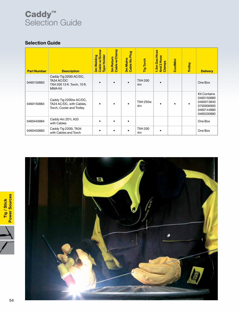
54
Tig
/ S
tick
Po
wer
So
urce
sCaddy™
Selection Guide
Selection Guide
Part Number Description 3m W
eld
ing
C
able
w/S
crew
Ty
pe
Ho
lder
3m R
etur
n C
able
w/C
lam
p
3m M
ains
C
able
No
Plu
g
Tig
To
rch
1.5m
Gas
Ho
se
And
2 H
ose
C
lam
ps
Co
olM
ini
Tro
lley
Delivery
0460150883
Caddy Tig 2200i AC/DC, TA34 AC/DC TXH 200 13 ft. Torch, 10 ft. MMA Kit
• • •TXH 200 4m
• One Box
0460150884Caddy Tig 2200iw AC/DC, TA24 AC/DC, with Cables, Torch, Cooler and Trolley
• • •TXH 250w 4m
• • •
Kit Contains 0460150880 0460013840 0700006900 0460144880 0460330880
0460445884Caddy Arc 201i, A33 with Cables
• • • One Box
0460450883Caddy Tig 2200i, TA34 with Cables and Torch
• • •TXH 200 4m
• One Box
55
Torches
TXH™ Air/WaterCooled Torches
� Ergonomic design, user friendly controls at fingertip
� Rugged construction - trouble-free operation with low maintenance
� Flexible heads offer un limited versatility for hard to reach applications (TXH 120F, 150F, 200F and 250F only)
� Effective cooling system
� For use with Caddy Tig and Caddy Arc machines with OKC connectors
� Remote control models available
F = Flexible head V = Gas valve r = Remote Note: See Genuine Heliarc Accessories pages for cups, collets, collet bodies * Requires Remote Adaptor Kit RA T1
AccessoriesRemote Adaptor Kit RA T1, for Remote Function torches onlyIncludes holder and 0,25 m cable12-pole ...................................045949191210-pole ....................................0459491913
Accessory Kits TXH-150, 200, 400 ......................999126 TXH-120, 250 ..............................999127
TIG torch holder ....................0760022400
Ordering Information
Product Data Page ................................................ ARC-23254
Use with HW-26 Consumables TXH 200F, 26 ft. ................. 0460012882
Use with HW-17 Consumables TXH 150, 13 ft.. .................. 0460011840 TXH 150, 26 ft. ................... 0460011880TXH 150V, 13 ft.. ................ 0460011841
Air Cooled Torches - 25mm OKC Connector
Use with HW-9 ConsumablesTXH 120r, 13 ft. .................. 0462010842TXH 120r, 26 ft. .................. 0462010882 TXH 120Fr, 13 ft. ................ 0462010844 TXH 120Fr, 26 ft. ................ 0462010884
Use with HW-17 ConsumablesTXH 150r, 13 ft. .................. 0462011842TXH 150Fr, 13 ft. ................ 0462011845TXH 150Fr, 26 ft. ................ 0462011885
Use with HW-26 ConsumablesTXH 200r, 13 ft. .................. 0462012840 TXH 200r, 26 ft. .................. 0462012880 TXH 200Fr, 26 ft. ................ 0462012882
Air Cooled Torches with Remote Function - 50mm OKC Connector*
Use with HW-20 ConsumablesTXH 250w, 13 ft. ................ 0460013840TXH 250w, 26 ft. ................ 0460013880 TXH 250wF, 13 ft. .............. 0460013841TXH 250wF, 26 ft. .............. 0460013881
Use with HW-18 ConsumablesTXH 400w, 13 ft. ................ 0460014840TXH 400w, 26 ft. ................ 0460014880TXH 400w HD, 13 ft. .......... 0460014841TXH 400w HD, 26 ft. .......... 0460014881
Water Cooled Torches - 50mm OKC Connector
Use with HW-20 ConsumablesTXH 250wr, 13 ft. ............... 0462013840TXH 250wr, 26 ft. ............... 0462013880 TXH 250wFr, 13 ft. ............. 0462013841TXH 250wFr, 26 ft. ............. 0462013881
Use with HW-18 ConsumablesTXH 400wr, 13 ft. ............... 0462014840TXH 400wr, 26 ft. ............... 0462014880TXH 400wr HD, 13 ft.......... 0462014841TXH 400wr HD, 13 ft.......... 0462014881
Water Cooled Torches with Remote Function - 50mm OKC Connector *
Use with HW-9 ConsumablesTXH 120, 13 ft.. .................. 0460010842TXH 120, 26 ft. ................... 0460010882 TXH 120F, 13 ft. ................. 0460010844 TXH 120F, 26 ft. ................. 0460010884
Use with HW-17 ConsumablesTXH 150, 13 ft. ................... 0460011842TXH 150, 26 ft. ................... 0460011882TXH 150V, 13 ft. ................. 0460011843TXH 150V, 26 ft. ................. 0460011883TXH 150F, 13 ft. ................. 0460011845 TXH 150F, 26 ft. ................. 0460011885
Use with HW-26 ConsumablesTXH 200, 13 ft. ................... 0460012840 TXH 200, 26 ft. ................... 0460012880 TXH 200V, 13 ft. ................. 0460012841TXH 200V, 26 ft. ................ 0460012881TXH 200F, 13 ft. ................. 0460012842TXH 200F, 26 ft. ................. 0460012882
Air Cooled Torches - 50mm OKC Connector
56
Hel
iarc
®
Torc
hes
Genuine HeliarcTig Torch Selection Guide
ESAB has made a model change on the HW-9 series torches. The new designation for that series of torches is HW-90.
ESAB has made a model change on the HW-20A series torches. The new designation for that series of torches is HW-9.
Gas-Cooled Torches
Old Designation New Designation
HW-9 HW-90
HW-20A HW-9
HW-20AR HW-9R
HW-20AF HW-9F
HW-20ARV HW-9RV
HW-20ARV2 HW-9RV2
DescriptionRating @ 50%
Duty Cycle Har
d B
od
y1 w
/HFC
Sili
con
Rub
ber2
60˚ H
ead
A
ngle
70/7
5˚
Hea
d A
ngle
90˚ H
ead
A
ngle
180
˚ Hea
d
Ang
le
Flex
Hea
d
wit
h va
lve
wit
hout
va
lve
Comments
HW-24 80 A • • • • miniature, ultra light torch
HW-90 120 A • • • • small, lightweight torch
HW-9 140 A • • • compact, air-cooled version of HW-20
HW-9RV-2 140 A • • • separate power cable / gas hose
HW-9RV 140 A • • • rotary valve
HW-9F 140 A • • • flexible head version of HW-20A
HW-17 150 A • • • • • rotary valve / sliding valve avai.
HW-17-2 150 A • • • • separate power cable / gas hose
HW-17R 150 A • • • • • rotary valve available
HW-17R-2 150 A • • • • separate power cable / gas hose
HW-17F 150 A • • • • flexible head version
HW-17F-2 150 A • • • • separate power cable / gas hose
HW-26 220 A • • • • popular heavy duty air-cooled torch
HW-26-2 220 A • • • • separate power cable / gas hose
HW-26R 220 A • • • • concentric power cable
HW-26R-2 220 A • • • • separate power cable / gas hose
HW-26F 220 A • • • • flexible head version
HW-26F-2 220 A • • • separate power cable / gas hose
Description Rating@ 50%
Duty Cycle Har
d B
od
y1 w
/HFC
Sili
con
Rub
ber
2
60˚ H
ead
A
ngle
70/
75˚
Hea
d A
ngle
90˚ H
ead
A
ngle
180˚
Hea
d
Ang
le
Flex
Hea
d
wit
h va
lve
wit
hout
va
lve
Comments
HW-20 300 A • • • compact, high current torch
HW-20R 300 A • • • compact, high current torch
HW-18 425 A • • • • general purpose
HW-18R 425 A • • • general purpose
HW-25F 200 A • • • • flexable head, water torch
HW-27 400 A • • • rear loading machine torch
Water-Cooled Torches
Hard Body Torches with HFC™ (High temperature Fiber reinforced Composite material) provide the best performance, heat resistance, abrasion resistance, and high frequency resistance.
Rubber bodies provide improved resistance to breakage in rough duty.
57
Heliarc
®
Torches
HW-24 Torch Family - 80 AmpGas-Cooled Torches
� Designed to reach into tight places
� Ideal for confined, cramped areas
� High flexibility one-piece cable
�Miniature head provides maximum accessibility to corners and tight joints
� Excellent visibility
� Gas lens available for improved shielding
Concentric cable 60˚ head, 12 1⁄2 ft. ...............................................................45V17 90˚ head, 12 1⁄2 ft. ............................................................. 527712
Specifications
Ordering Information
Cups, Collets and Collet BodiesElectrode Size .020 .040 1/16 —
Standard Collet 53N15 53N16 53N14 —
Standard Collet Body 53N17 53N18 53N19 —
Gas Lens Collet 53N62 53N63 53N64 —
Gas Lens Collet Body** 45V41 45V42 45V43 —
Cup Number .165 in. I.D. 4 =1⁄4 5 =5⁄16 6 =3⁄8 7=7⁄16
Ceramic Cup 53N23 53N24 53N25 53N27 —
Gas Lens High-Impact Cup — 53N58 53N59 53N60 53N61
**Also order insulator 53N66
HW-24
Gun Capacity
75 A, 100% duty cycle ac or dc with standard accessories
100 A, 100% duty cycle ac or dc with gas lens accessories
80 A, 50% duty cycle ac or dc with standard accessories
Dimensions
Length 7 3/4 in. (197 mm)
Length of Head 1 1/16 in. (27 mm)
Diameter of Head 5/8 in. (16 mm)
Head Angle 60 or 90 degree
Handle Diameter 3/4 in. (19 mm)
Weight (less service lines) 2.5 oz. (71 gm)

58
Hel
iarc
®
Torc
hes
HW-24 Torch Family - 80 AmpGas-Cooled Torches
Torch Parts and Accessories
2
3
4
5
6
7
8
9
1
10
11
12
Item Part Number Description
145V16 Body, HW-24 (60˚)
527713 Body, HW-24 (90˚)
2 105Z55 Handle, HW-24
3 – Collet
4 – Collet Body*
5 – Gas Cups
6 53N66 Insulator, Gas Lens (Required for gas lens)
7 53N22 Insulator Gasket - Standard
8 – Gas Lens Collet
9 – Gas Lens Collet Body
10 – Gas Lens Cup
11 53N43 Power Cable Adaptor
12 56Y38 Power Cable, 12 1⁄2 ft.
*Note: Order wrench (53N20) for HW-24 collet body.

59
Heliarc
®
Torches
� HW-90 is designed for small, confined areas where accessibility is the primary concern
� High flexibility one-piece cable
� Available in 60/120 degree heads by exchanging cap and cup. Also available in Pencil style (180 degree)
� Excellent visibility
� Gas lens available for improved shielding
60°Concentric cable 12 1⁄2 ft. .............................................................................. 16X28 25 ft. .................................................................................. 16X44PencilConcentric cable, 12 1⁄2 ft. ..................................................... 16X47
HW-90 Torch Family - 120 AmpGas-Cooled Torches
Specifications
Ordering Information
Cups, Collects and Collect BodiesElectrode Size .020 .040 1/16 —
Standard Collet — 84Z35 84Z33 —
Standard Collet Body — 105Z27 — —
Gas Lens Collet Body* 45V41 45V42 45V43 —
Cup Number 4 =1⁄4 5 =5⁄16 6 =3⁄8 7=7⁄16
High-Impact Cup 14N65 14N66 14N67 —
Gas Lens High-Impact Cup 53N58 53N59 53N60 53N61
* Also order adaptor 45V52 / insulator 53N85
HW-90
Gun Capacity
110 A, 100% duty cycle ac or dc with standard accessories
110 A, 100% duty cycle ac or dc with gas lens accessories
120 A, 50% duty cycle ac or dc
Dimensions 60° Pencil
Length6 3⁄4 in.
(171 mm)7 1⁄8 in.
(181 mm)
Length of Head
Short Cap3 1⁄8 in.
(79 mm)1 1⁄16 in. (27 mm)
Long Cap7 1⁄8 in.
(181 mm)
Diameter of Head 19⁄32 in. (15 mm) 5⁄8 in. (16 mm)
Head Angle 60/120° 180°
Handle Diameter 3⁄4 in. (19 mm) 3⁄4 in. (19 mm)
Weight (less service lines) 3 oz. (84 gm) 5 oz. (140 gm)
60
Hel
iarc
®
Torc
hes
HW-90 Torch Family - 120 AmpGas-Cooled Torches
Torch Parts and Accessories
1
2
3
4
5
6
7
8
910 11
12
6
8
14
13
16
15
Item Part Number Description
156Y35 Body, HW-90 (60/120˚)
86Z24 Body, HW-90P (180˚)
2 105Z55 Handle, HW-90 / HW-90P
3 56Y40 Long Torch Cap w/o O-Ring (85W49)
4 84Z31 Short Torch Cap w/o O-Ring (85W49)
5 – Collet
6 85W49 O-Ring
7 105Z27 Collet Body
8 105Z26 Insulator Sleeve
9 – High-Impact Cup
10 – Ceramic Cup
11 – Gas Lens Cup
12 – Gas Lens Collet Body
13 53N85 Gas Lens Insulator
14 45V52 Gas Lens Adaptor
15 53N43 Power Cable Adaptor
1656Y38 Power Cable, 12 1⁄2 ft.
56Y97 Power Cable, 25 ft.
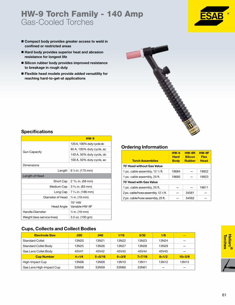
61
Heliarc
®
Torches
� Compact body provides greater access to weld in confined or restricted areas
� Hard body provides superior heat and abrasion resistance for longest life
� Silicon rubber body provides improved resistance to breakage in rough duty
� Flexible head models provide added versatility for reaching hard-to-get-at applications
HW-9 Torch Family - 140 AmpGas-Cooled Torches
Specifications
Ordering Information
Cups, Collects and Collect Bodies
Torch Assemblies
HW-9 Hard Body
HW-9R Silicon Rubber
HW-9F Flex Head
70˚ Head without Gas Value
1 pc. cable assembly, 12 1⁄2 ft. 19684 — 19922
1 pc. cable assembly, 25 ft. 19685 — 19923
70˚ Head with Gas Value
1 pc. cable assembly, 25 ft. — — 19611
2 pc. cable/hose assembly, 12 1⁄2 ft. — 34561 —
2 pc. cable/hose assembly, 25 ft. — 34562 —
Electrode Size .020 .040 1/16 3/32 1/8 —
Standard Collet 13N20 13N21 13N22 13N23 13N24 —
Standard Collet Body 13N25 13N26 13N27 13N28 13N29 —
Gas Lens Collet Body 45V41 45V42 45V43 45V44 45V45 —
Cup Number 4 =1⁄4 5 =5/16 6 =3/8 7=7/16 8=1/2 10= 5/8
High-Impact Cup 13N08 13N09 13N10 13N11 13N12 13N13
Gas Lens High-Impact Cup 53N58 53N59 53N60 53N61 — —
HW-9
Gun Capacity
120 A, 100% duty cycle dc
85 A, 100% duty cycle, ac
140 A, 50% duty cycle, dc
100 A, 50% duty cycle, ac
Dimensions
Length 6 7⁄8 in. (175 mm)
Length of Head
Short Cap 2 19⁄64 in. (58 mm)
Medium Cap 3 9⁄32 in. (83 mm)
Long Cap 7 5⁄16 in. (186 mm)
Diameter of Head 3⁄4 in. (19 mm)
Head Angle70° HW Variable HW-9F
Handle Diameter 3⁄4 in. (19 mm)
Weight (less service lines) 3.5 oz. (100 gm)
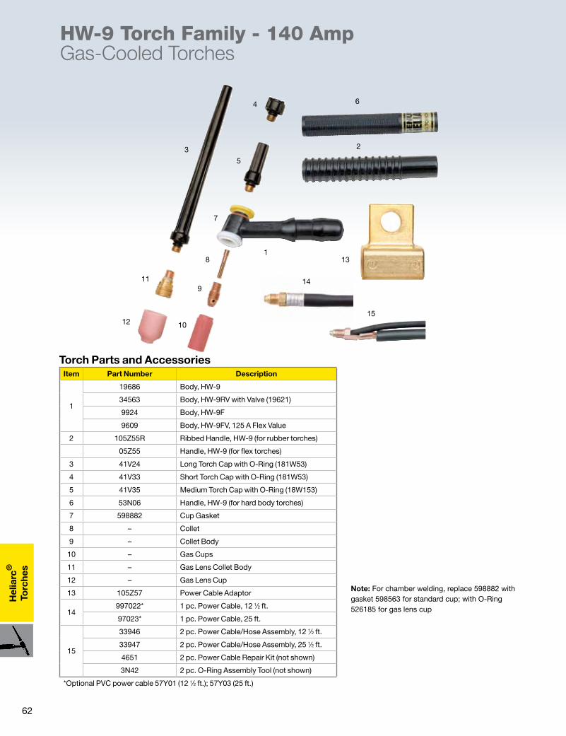
62
Hel
iarc
®
Torc
hes
HW-9 Torch Family - 140 AmpGas-Cooled Torches
Torch Parts and Accessories
Note: For chamber welding, replace 598882 with gasket 598563 for standard cup; with O-Ring 526185 for gas lens cup
23
4
5
6
7
8
9
1
10
11
12
13
14
15
Item Part Number Description
1
19686 Body, HW-9
34563 Body, HW-9RV with Valve (19621)
9924 Body, HW-9F
9609 Body, HW-9FV, 125 A Flex Value
2 105Z55R Ribbed Handle, HW-9 (for rubber torches)
05Z55 Handle, HW-9 (for flex torches)
3 41V24 Long Torch Cap with O-Ring (181W53)
4 41V33 Short Torch Cap with O-Ring (181W53)
5 41V35 Medium Torch Cap with O-Ring (18W153)
6 53N06 Handle, HW-9 (for hard body torches)
7 598882 Cup Gasket
8 – Collet
9 – Collet Body
10 – Gas Cups
11 – Gas Lens Collet Body
12 – Gas Lens Cup
13 105Z57 Power Cable Adaptor
14997022* 1 pc. Power Cable, 12 1⁄2 ft.
97023* 1 pc. Power Cable, 25 ft.
15
33946 2 pc. Power Cable/Hose Assembly, 12 1⁄2 ft.
33947 2 pc. Power Cable/Hose Assembly, 25 1⁄2 ft.
4651 2 pc. Power Cable Repair Kit (not shown)
3N42 2 pc. O-Ring Assembly Tool (not shown)
*Optional PVC power cable 57Y01 (12 1⁄2 ft.); 57Y03 (25 ft.)
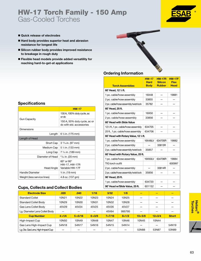
63
Heliarc
®
Torches
� Quick release of electrodes
� Hard body provides superior heat and abrasion resistance for longest life
� Silicon rubber body provides improved resistance to breakage in rough duty
� Flexible head models provide added versatility for reaching hard-to-get-at applications
HW-17 Torch Family - 150 AmpGas-Cooled Torches
Specifications
Ordering Information
Cups, Collects and Collect Bodies
Torch Assemblies
HW-17 Hard Body
HW-17R Silicon Rubber
HW-17F Flex Head
60˚ Head, 12 1⁄2 ft.
1 pc. cable/hose assembly 16X48 — 19881
2 pc. cable/hose assembly 33855 — —
2 pc. cable/hose assembly twist lock 35782 — —
60˚ Head, 25 ft.
1 pc. cable/hose assembly 16X50 — —
2 pc. cable/hose assembly 33856 — —
60˚ Head with Slide Value
121⁄2 ft.,1 pc. cable/hose assembly 634705 — —
25 ft., 1 pc. cable/hose assembly 634706 — —
60˚ Head with Rotary Value, 12 1⁄2 ft.
1 pc. cable/hose assembly 16X48LV 634705R 19882
2 pc. cable/hose assembly — 33813R —
2 pc. cable/hose assembly twist lock 35857 — —
60˚ Head with Rotary Value, 25 ft.
1 pc. cable/hose assembly 16X50LV 634706R 19884
TIG torch outfit 600997
2 pc. cable/hose assembly — 33814R —
2 pc. cable/hose assembly twist lock 35856 — —
90˚ Head, 25 ft.
1 pc. cable/hose assembly 634720 — —
90˚ Head w/Slide Value, 25 ft. 601152 — —
Electrode Size .020 .040 1/16 3/32 1/8 — — —
Standard Collet 10N21 10N22 10N23 10N24 10N25 — — —
Standard Collet Body 10N29 10N30 10N31 10N32 10N28 — — —
Gas Lens Collet Body 45V29 45V24 45V25 45V26 45V27 — — —
Lg. Diameter Lens Collet Body — — — 45V64 995795 — — —
Cup Number 4 =1⁄4 5 =5/16 6 =3/8 7=7/16 8=1/2 10= 5/8 12=3/4 Short
High-Impact Cup 10N50 10N49 10N48 10N47 10N46 10N45 10N44
Gas Lens High-Impact Cup 54N18 54N17 54N16 54N15 54N14 — — 54N19
Lg. Dia. Gas Lens, High-Impact Cup — — — — — 53N88 53N87 53N89
HW-17
Gun Capacity
130 A, 100% duty cycle, ac or dc
150 A, 50% duty cycle, ac or dc with std. accessories
Dimensions
Length 6 7⁄8 in. (175 mm)
Length of Head
Short Cap 3 13⁄16 in. (97 mm)
Medium Cap 5 1⁄4 in. (133 mm)
Long Cap 7 7⁄16 in. (189 mm)
Diameter of Head 51⁄64 in. (20 mm)
Head Angle
60° or 90° HW-17, HW-17R Variable HW-17F
Handle Diameter 3⁄4 in. (19 mm)
Weight (less service lines) 4.8 oz. (137 gm)
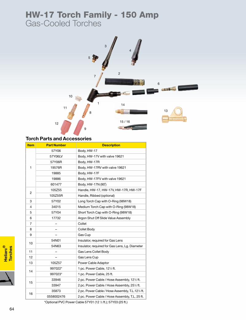
64
Hel
iarc
®
Torc
hes
HW-17 Torch Family - 150 AmpGas-Cooled Torches
Torch Parts and Accessories
2
34
5
6
7
8
9
1
10
11
12
13
14
15 / 16
Item Part Number Description
1
57Y06 Body, HW-17
57Y06LV Body, HW-17V with valve 19621
57Y06R Body, HW-17R
19576R Body, HW-17RV with valve 19621
19885 Body, HW-17F
19886 Body, HW-17FV with valve 19621
601477 Body, HW-17N (90˚)
2105Z55 Handle, HW-17, HW-17V, HW-17R, HW-17F
105Z55R Handle, Ribbed (optional)
3 57Y02 Long Torch Cap with O-Ring (98W18)
4 34015 Medium Torch Cap with O-Ring (98W18)
5 57Y04 Short Torch Cap with O-Ring (98W18)
6 17732 Argon Shut Off Slide Value Assembly
7 – Collet
8 – Collet Body
9 – Gas Cup
1054N01 Insulator, required for Gas Lens
54N63 Insulator, required for Gas Lens, Lg. Diameter
11 – Gas Lens Collet Body
12 – Gas Lens Cup
13 105Z57 Power Cable Adaptor
14997022* 1 pc. Power Cable, 121⁄2 ft.
997023* 1 pc. Power Cable, 25 ft.
1533946 2 pc. Power Cable / Hose Assembly, 121⁄2 ft.
33947 2 pc. Power Cable / Hose Assembly, 251⁄2 ft.
1635873 2 pc. Power Cable / Hose Assembly, T.L.121⁄2 ft.
0558002476 2 pc. Power Cable / Hose Assembly, T.L. 25 ft.
*Optional PVC Power Cable 57Y01 (12 1⁄2 ft.); 57Y03 (25 ft.)

65
Heliarc
®
Torches
HW-26 Torch Family - 220 AmpGas-Cooled Torches
� Quick release of electrodes
� Hard body provides superior heat and abrasion resistance for longest life
� Silicon rubber body provides improved resistance to breakage in rough duty
� Flexible head models provide added versatility for reaching hard-to-get-at applications
Specifications
Cups, Collects and Collect Bodies
Ordering Information
Torch Assemblies
HW-26 Hard Body
HW-26R Silicon Rubber
HW-26F Flex Head
75˚ Head, 12 1⁄2 ft. without Value
1 pc. cable / hose assembly 17137 — 33848
2 pc. cable / hose assembly 33857 — —
75˚ Head, 25 ft. without Value
1 pc. cable / hose assembly 46V29 — 33849
2 pc. cable / hose assembly 948127 — —
75˚ Head w/Rotary Value,12 1⁄2 ft.
1 pc. cable / hose assembly 17138 17138R 33850
2 pc. cable / hose assembly — — 33852
2 pc. cable / hose assembly twist lock 35858
75˚ Head w/Rotary Value, 25 ft.
1 pc. cable / hose assembly 46V27 46V27R 33851
2 pc. cable / hose assembly 948128 948128R 33853
Electrode Size .020 .040 1/16 3/32 1/8 — — —
Standard Collet 10N21 10N22 10N23 10N24 10N25 — — —
Standard Collet Body 10N29 10N30 10N31 10N32 10N28 — — —
Gas Lens Collet Body 45V29 45V24 45V25 45V26 45V27 — — —
Lg. Diameter Lens Collet Body — — — 45V64 995795 — — —
Cup Number 4 =1⁄4 5 =5/16 6 =3/8 7=7/16 8=1/2 10= 5/8 12=3/4 Short
High-Impact Cup 10N50 10N49 10N48 10N47 10N46 10N45 10N44
Gas Lens High-Impact Cup 54N18 54N17 54N16 54N15 54N14 — — 54N19
Lg. Dia. Gas Lens, High-Impact Cup — — — — — 53N88 53N87 53N89
HW-26
Gun Capacity
160 A, 100% duty cycle, ac or dc with std. accessories
200 A, 100% duty cycle, ac or dc with std. accessories
150 A, 50% duty cycle, ac or dc with std. accessories
Dimensions
Length 8 7⁄8 in. (225 mm)
Length of Head
Short Cap 3 3⁄4 in. (95 mm)
Medium Cap 5 3⁄8 in. (136 mm)
Long Cap 7 3⁄8 in. (187 mm)
Diameter of Head 29⁄32 in. (23 mm)
Head Angle75° HW-26 Variable HW-126F
Handle Diameter 1 7⁄32 in. (31 mm)
Weight (less service lines) 7.75 oz. (221 gm)
66
Hel
iarc
®
Torc
hes
HW-26 Torch Family - 220 AmpGas-Cooled Torches
Torch Parts and Accessories
2
3
4
5 6
7
8
9
1
10
11
12
13
14
15
Item Part Number Description
1
45V65 Body, HW-26
598478 Body, HW-26V with valve (598279)
45V65R Body, HW-26R
598478R Body, HW-26RV with valve (19622)
34014 Body, HW-26F Flex Head
34013 Body, HW-26FV with valve (34074)
219624 Ribbed Handle, HW-26R (for rubber body)
10N15 Handle, HW-26F (for flex body)
3 57Y02 Long Torch Cap with O-Ring (98W18)
4 34015 Medium Torch Cap with O-Ring (98W18)
5 57Y04 Short Torch Cap with O-Ring (98W18)
6 54N84 Handle, HW-26 (for hard body)
7 – Collet
8 – Collet Body
9 – Gas Cup
1054N01 Insulator, required for Gas Lens
54N63 Insulator, required for Gas Lens, Lg. Diameter
11 – Gas Lens Collet Body
12 – Gas Lens Cup
13 45V62 Power Cable Adaptor
1446V28 1 pc. Power Cable, 12 1⁄2 ft.
46V30 1 pc. Power Cable, 25 ft.
15
33697 2 pc. Power Cable / Hose Assembly, 12 1⁄2 ft.
33698 2 pc. Power Cable / Hose Assembly, 25 1⁄2 ft.
35874 2 pc. Power Cable / Hose Assembly, T.L.12 1⁄2 ft.
67
Heliarc
®
Torches
HW-20 Torch Family - 300 Amp Water-Cooled Torches
� Compact water-cooled design for higher current applications in confined areas
� Hard body w/HFCTM (HW-20) provides superior heat and abrasion resistance - available in 2 versions
� Economical silicon rubber body (HW-20R) provides resistance to breakage
Cups, Collects and Collect Bodies
Specifications
Ordering Information
Torch Assemblies
HW-20 Hard Body
HW-20 Silicon Rubber
70˚ Head
Cable / hose assembly, 12 1⁄2 ft. 948084 948084R
Cable / hose assembly, 25 ft. 948085 948085R
Electrode Size .020 .040 1/16 3/32 1/8 —
Standard Collet 13N20 13N21 13N22 13N23 13N24 —
Standard Collet Body 13N25 13N26 13N27 13N28 13N29 —
Gas Lens Collet Body 45V41 45V42 45V43 45V44 45V45 —
Cup Number 4 =1⁄4 5 =5/16 6 =3/8 7=7/16 8=1/2 10= 5/8
High-Impact Cup 13N08 13N09 13N10 13N11 13N12 13N13
Gas Lens High-Impact Cup 53N58 53N59 53N60 53N61 — —
For selection of special ceramic or sleeved cups, see Accessories following Torches.
HW-20
Gun Capacity
240 A, 100% duty cycle, ac or dc with std. accessories
250 A, 100% duty cycle, ac or dc with gas lens accessories
300 A, 50% duty cycle, ac or dc
Dimensions
Length 6 7⁄8 in. (175 mm)
Length of Head
Short Cap 2 19⁄64 in. (58 mm)
Medium Cap 3 9⁄32 in. (83 mm)
Long Cap 7 5⁄16 in. (186 mm)
Diameter of Head 3⁄4 in. (19 mm)
Head Angle 70°
Handle Diameter 3⁄4 in. (19 mm)
Weight (less service lines) 3.5 oz. (100 gm)
Cooling Requirements 1 qt. min. (0.94 l/min)
68
Hel
iarc
®
Torc
hes
HW-20 Torch Family - 300 Amp Water-Cooled Torches
Torch Parts and Accessories
2
3
4
5
6
7
8
9
1
10
11
12
13
14
1516
Item Part Number Description
1948020 Body, HW-20 with O-Ring (85W49)
948020R Body, HW-20R
2 53N06 Handle, HW-20
3 41V24 Long Torch Cap with O-Ring (181W53)
4 41V33 Short Torch Cap with O-Ring (181W53)
5 41V35 Medium Torch Cap with O-Ring (181W53)
6 598882 Cup Gasket
7 – Collet
8 – Collet Body
9 – Gas Cup
10 – Gas Lens Collet Body
11 – Gas Lens Cup
12 45V11 Power Cable Adaptor
1345V03 Power Cable, 12 1⁄2 ft.
45V04 Power Cable, 25 ft.
1445V09 Gas Hose, 12 1⁄2 ft.
45V10 Gas Hose, 25 ft.
1545V07 Water Hose, 12 1⁄2 ft.
45V08 Water Hose, 25 ft.
16
53N04 Hose Clamp
13N42 O-Ring Assembly Tool (not shown)
11N16 Water Adaptor (5⁄8 - 18 LH to 1⁄4 NPT) (not shown)
17 85W49 O-Ring
69
Heliarc
®
Torches
HW-18 Torch Family - 425 Amp Water-Cooled Torches
� The industry standard water-cooled general purpose torch
� Ideal for production welding
� Lightweight - reduces operator fatigue
�Watertight - brazed, closed cooling system
� Gas lens available for improved shielding
� Hard body w/HFCTM (HW-18) provides superior heat and abrasion resistance for the longest life
� Economical silicon rubber body (HW-18R) provides resistance to breakage
Specifications
Ordering Information
Cups, Collects and Collect Bodies
HW-18
Gun Capacity
300 A, 100% duty cycle, ac or dc with std. accessories
375 A, 100% duty cycle, ac or dc with gas lens accessories
425 A, 50% duty cycle, ac or dc
Dimensions
Length 10 1⁄2 in. (267 mm)
Length of Head
Short Cap 3 3⁄16 in. (81 mm)
Medium Cap 5 7⁄16 in. (138 mm)
Long Cap 7 7⁄16 in. (189 mm)
Diameter of Head 29⁄32 in. (23 mm)
Head Angle 60°
Handle Diameter 1 1⁄16 in. (27 mm)
Weight (less service lines) 7 oz. (200 gm)
Cooling Requirements 1 qt. min. (0.94 l/min)
Torch Assemblies
HW-18 Hard Body
HW-18 Silicon Rubber
60˚ Head
Cable / hose assembly, 12 1⁄2 ft. 948361 948361R
Cable / hose assembly, 25 ft. 948362 948362R
Electrode Size .020 .040 1/16 3/32 1/8 — — —
Standard Collet 10N21 10N22 10N23 10N24 10N25 — — —
Standard Collet Body 10N29 10N30 10N31 10N32 10N28 — — —
Gas Lens Collet Body 45V29 45V24 45V25 45V26 45V27 — — —
Lg. Diameter Lens Collet Body — — — 45V64 995795 — — —
Cup Number 4 =1⁄4 5 =5/16 6 =3/8 7=7/16 8=1/2 10= 5/8 12=3/4 Short
High-Impact Cup 10N50 10N49 10N48 10N47 10N46 10N45 10N44 —
Gas Lens High-Impact Cup 54N18 54N17 54N16 54N15 54N14 — — 54N19
Lg. Dia. Gas Lens, High-Impact Cup — — — — — 53N88 53N87 53N89
70
Hel
iarc
®
Torc
hes
HW-18 Torch Family - 425 Amp Water-Cooled Torches
Torch Parts and Accessories
2
3
4
5
6
7
8
9
1
10
11
12
13
14
15
16
16
Item Part Number Description
1948350 Body, HW-18
948350R Body, HW-18R
210N15 Handle, HW-18
10N15A Handle, HW-18R
3 57Y02 Long Torch Cap with O-Ring (98W18)
4 34015 Medium Torch Cap with O-Ring (98W18)
5 57Y04 Short Torch Cap with O-Ring (98W18)
6 – Collet
7 – Collet Body
8 – Gas Cups
954N01 Insulator, required for Gas Lens
54N63 Insulator, required for Gas Lens, Lg. Diameter
10 – Gas Lens Collet Body
11 – Gas Lens Cup
12 45V11 Power Cable Adaptor
1340V64 Power Cable, 12 1⁄2 ft.
41V29 Power Cable, 25 ft.
1440V75 Gas Hose, 12 1⁄2 ft.
41V30 Gas Hose, 25 ft.
1540V74 Water Hose, 12 1⁄2 ft.
41V32 Water Hose, 25 ft.
1698W43 Hose Clamp
11N16 Water Adaptor (5⁄8 LH to 1⁄4 NPT) (not shown)
71
Heliarc
®
Torches
� Small, Lightweight
� Flexible head to access difficult joints
HW-25 Torch Family - 200 Amp Water-Cooled Torches
Specifications
Ordering Information
Cups, Collects and Collect Bodies
HW-25
Gun Capacity
200 A, 100% duty cycle, ac or dc with std. accessories
210 A, 50% duty cycle, ac or dc with std. or gas lens
Dimensions
Length 10 1⁄2 in. (267 mm)
Length of Head 4 7⁄8 in. (124 mm)
Diameter of Head 3⁄4 in. (19 mm)
Head Angle Flexible
Handle Diameter 3⁄4 in. (19 mm)
Weight (less service lines) 14 oz. (400 gm)
Cooling Requirements 1 qt. min. (0.94 l/min)
Torch AssembliesHW-25
Silicon Rubber
Flexible Head
HW-25 – 12 with 12 ft. cable 45V36
HW-25 – 25 with 25 ft. cable 45V37
Electrode Size .020 .040 1/16 3/32 1/8 —
Standard Collet 13N20 13N21 13N22 13N23 13N24 —
Standard Collet Body 13N25 13N26 13N27 13N28 13N29 —
Gas Lens Collet Body 45V41 45V42 45V43 45V44 45V45 —
Cup Number 4 =1⁄4 5 =5/16 6 =3/8 7=7/16 8=1/2 10= 5/8
High-Impact Cup 13N08 13N09 13N10 13N11 13N12 13N13
Gas Lens High-Impact Cup 53N58 53N59 53N60 53N61 — —
72
Hel
iarc
®
Torc
hes
1
2
3
4
5
6
7
HW-25 Torch Family - 200 Amp Water-Cooled Torches
Torch Parts and AccessoriesItem Part Number Description
1 45V38 Body, HW-25
2 53N55 Handle, HW-25
3 53N45 Flex Sleeve Insulator
4 53N47 Insulator
5 – Collet
6 – Collet Body
7 – Ceramic Cup
45V03 Power Cable, 12 1⁄2 ft.
45V04 Power Cable, 25 ft.
45V07 Water Hose, 12 1⁄2 ft.
45V08 Water Hose, 25 ft.
45V09 Gas Hose, 12 1⁄2 ft.
45V10 Gas Hose, 25 ft.
11N16 Water Adaptor (5⁄8 18 LH TO 1⁄4 NPT) (not shown)

73
Heliarc
®
Torches
� Front or back loaded
� Internal tungsten adjustment
�Model A with 9" length is designed for clamp-type fixture
�Model B with 20" length is designed for pinion-type fixture
HW-27 Torch Family - 400 Amp Water-Cooled Torches
Specifications
Ordering Information
Cups, Collects and Collect Bodies
HW-27
Gun Capacity
400 A, 100% duty cycle, ac or dc with high impact cups
500 A, 100% duty cycle, ac or dc with metal nozzles
400 A, 50% duty cycle, ac or dc
Dimensions 27A 27B
Length 9 in. (230 mm) 20 in. (500 mm)
Diameter of Torch 1 3⁄8 in. (34 mm)
Weight (less service lines) 24 oz. (680 gm) 36 oz. (1021 gm)
Cooling Requirements 2 qt. min. (1.91 l/min)
Maximum Pressure 50 psi
Electrode Capacity .040 - 1⁄4 in. diameter
Torch AssembliesHW-27
Silicon Rubber
HW-27A - 9 in.
HW-27A – 4 with 4 ft. cable 20955
HW-27A – 12 with 12 ft. cable 20954
HW-27B – 20 in.
HW-27BL – 4 with 4 ft. cable 20017
HW-27B – 12 with 12 ft. cable 20018
Electrode Size .040 1/16 3/32 1/8 5/32 3/16 1/4
Standard Collet 57N45 57N46 57N47 57N48 57N49 57N50 57N51
Standard Collet Body* — — 49V24 49V25 49V26 49V27 49V28
Cup Number 6=3/8 8=1/2 10=5/8 12=3/4 15=15/16 Short —
High-Impact Cup — 57N75 57N74 53N88 53N87 53N89 —
*Includes gasket - 57N56
74
Hel
iarc
®
Torc
hes
1
2
34
56
7
8
9
10
11
12
HW-27 Torch Family - 400 Amp Water-Cooled Torches
Torch Parts and AccessoriesItem Part Number Description
1 Q27A Body, 9" HW-27
Q27B Body, 20" HW-27
220957 Shaft / Knob Assembly (A-model)
20021 Shaft / Knob Assembly (B-model)
320956 Barrel (A-model)
20020 Barrel (B-model)
420957 Shaft Assembly (A-model)
20021 Shaft Assembly (B-model)
5 85W44 O-Ring
6 – Collet
7 – Collet Body
8 57N56 Gasket
9 – Gas Cup
10
20024 Power Cable, 12 1⁄2 ft.
20023 Power Cable, 4 1⁄2 ft.
20025 Water Cable, 4 1⁄2 ft.
20026 Water Cable, 12 1⁄2 ft.
20027 Gas Hose, 4 1⁄2 ft.
20028 Gas Hose, 12 1⁄2 ft.
11 20022 Boot
1220032
Options (HW-27B only) – HW-27B Back (32 pitch), rack length 11 11⁄16 in.
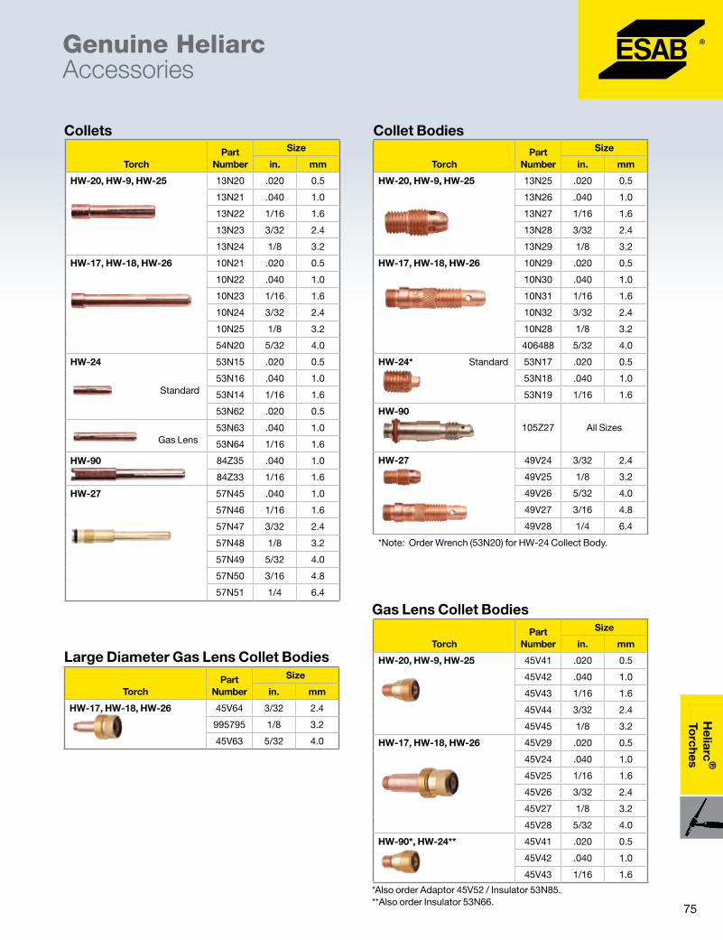
75
Heliarc
®
Torches
Genuine Heliarc Accessories
TorchPart
Number
Size
in. mm
HW-20, HW-9, HW-25 13N20 .020 0.5
13N21 .040 1.0
13N22 1/16 1.6
13N23 3/32 2.4
13N24 1/8 3.2
HW-17, HW-18, HW-26 10N21 .020 0.5
10N22 .040 1.0
10N23 1/16 1.6
10N24 3/32 2.4
10N25 1/8 3.2
54N20 5/32 4.0
HW-24 53N15 .020 0.5
Standard
53N16 .040 1.0
53N14 1/16 1.6
53N62 .020 0.5
Gas Lens
53N63 .040 1.0
53N64 1/16 1.6
HW-90 84Z35 .040 1.0
84Z33 1/16 1.6
HW-27 57N45 .040 1.0
57N46 1/16 1.6
57N47 3/32 2.4
57N48 1/8 3.2
57N49 5/32 4.0
57N50 3/16 4.8
57N51 1/4 6.4
Collets Collet Bodies
TorchPart
Number
Size
in. mm
HW-20, HW-9, HW-25 13N25 .020 0.5
13N26 .040 1.0
13N27 1/16 1.6
13N28 3/32 2.4
13N29 1/8 3.2
HW-17, HW-18, HW-26 10N29 .020 0.5
10N30 .040 1.0
10N31 1/16 1.6
10N32 3/32 2.4
10N28 1/8 3.2
406488 5/32 4.0
HW-24* Standard 53N17 .020 0.5
53N18 .040 1.0
53N19 1/16 1.6
HW-90
105Z27 All Sizes
HW-27 49V24 3/32 2.4
49V25 1/8 3.2
49V26 5/32 4.0
49V27 3/16 4.8
49V28 1/4 6.4
*Note: Order Wrench (53N20) for HW-24 Collect Body.
Gas Lens Collet Bodies
TorchPart
Number
Size
in. mm
HW-20, HW-9, HW-25 45V41 .020 0.5
45V42 .040 1.0
45V43 1/16 1.6
45V44 3/32 2.4
45V45 1/8 3.2
HW-17, HW-18, HW-26 45V29 .020 0.5
45V24 .040 1.0
45V25 1/16 1.6
45V26 3/32 2.4
45V27 1/8 3.2
45V28 5/32 4.0
HW-90*, HW-24** 45V41 .020 0.5
45V42 .040 1.0
45V43 1/16 1.6
*Also order Adaptor 45V52 / Insulator 53N85. **Also order Insulator 53N66.
TorchPart
Number
Size
in. mm
HW-17, HW-18, HW-26 45V64 3/32 2.4
995795 1/8 3.2
45V63 5/32 4.0
Large Diameter Gas Lens Collet Bodies
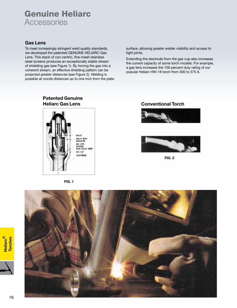
76
Hel
iarc
®
Torc
hes
Genuine Heliarc Accessories
FIG. 2
To meet increasingly stringent weld quality standards, we developed the patented GENUINE HELIARC Gas Lens. This stack of con centric, fine-mesh stainless steel screens produces an exceptionally stable stream of shielding gas (see Figure 1). By forcing the gas into a coherent stream, an effective shielding pattern can be projected greater distances (see Figure 2). Welding is possible at nozzle distances up to one inch from the plate
surface, allowing greater welder visibility and access to tight joints.
Extending the electrode from the gas cup also increases the current capacity of some torch models. For example, a gas lens increases the 100 percent duty rating of our popular Heliarc HW-18 torch from 300 to 375 A.
Patented Genuine Heliarc Gas Lens Conventional Torch
Torch With Gas Lens
FIG. 1
Gas Lens

77
Heliarc
®
Torches
Genuine Heliarc Accessories
Made from high strength alumina, have very good electrical insulating properties and exceptionally high impact resistance, heat resistance, thermal conductivity
and spatter build-up resistance. They are recommended for most welding operations except for use in confined areas.
High Impact Cups
TorchLength
(in.)Part
Number Size
Orifice
in. mm
HW-90
1 5⁄16
14N65 4 1⁄4 6.4
14N66 5 5⁄16 8
14N67 6 3⁄8 10
HW-17, HW-18, HW-26
1 27⁄32
10N50 4 1⁄4 6.4
10N49 5 5⁄16 8
10N48 6 3⁄8 10
10N47 7 7⁄16 11
10N46 8 1⁄2 12.5
10N45 10 5⁄8 16
10N44 12 3⁄4 19
HW-20, HW-9, HW-25
1 5⁄32
13N08 4 1⁄4 6.4
13N09 5 5⁄16 8
13N10 6 3⁄8 10
13N11 7 7⁄16 11
13N12 8 1⁄2 12.5
13N13 10 5⁄8 16
HW-27
1 27⁄32
57N75 6 3⁄8 10
57N74 8 1⁄2 12.5
53N88 10 5⁄8 16
53N87 12 3⁄4 19
1 5⁄16 53N89 15 15/16 24
Standard High-Impact Cups
TorchLength
(in.) Part
Number Size
Orifice
in. mm
HW-17, HW-18, HW-26
1 5/8
54N18 4 1/4 6.4
54N17 5 5/16 8
54N16 6 3/8 10
54N15 7 7/16 11
54N14 8 1/2 12.5
1 1/8 54N19 Short 11/16 17
HW-90, HW-20, HW-24, HW-9, HW-25
1
53N58 4 1/4 6.4
53N59 5 5/16 8
53N60 6 3/8 10
53N61 7 7/16 11
53N61S 8 1/2 12.7
Gas Lens High-Impact Cups
TorchLength
(in.)Part
Number Size
Orifice
in. mm
HW-17, HW-18, HW-26
1 7/8
57N75 6 3/8 10
57N74 8 1/2 12.5
53N88 10 5/8 16
53N87 12 3/4 19
1 5/16 53N89 Short 15/16 24
Large Diameter Gas Lens High-Impact Cups

78
Hel
iarc
®
Torc
hes
Made from Grade “A” lava materials are less impact and heat resistant than the high-impact cups, but can be expected to give very good service and long life. They perform very well in confined areas where excessive heat
is reflected back into the nozzle. These cups can be used at currents up to 250 A dcsp or ac, depending on arc time and cup size.
Ceramic Cups
Genuine Heliarc Accessories
Torch Length
(in.)Part
Number Size
Orifice
in. mm
HW-24
5/8
53N23 .165 .165 4
53N24 4 1/4 6.4
53N25 5 5/16 8
53N27 6 3/8 10
Ceramic Cups Special Ceramic Long Cups
TorchLength
(in).Part
Number Size
Orifice
in. mm
HW-20, HW-9, HW-25
1 7/8
796F70 3L 3/16 4.8
796F71 4L 1/4 6.4
796F72 5L 5/16 8
796F73 6L 3/8 10
HW-20 (X-Long), HW-9, HW-25 2 1/2
796F74 3XL 3/16 4.8
796F75 4XL 1/4 6.4
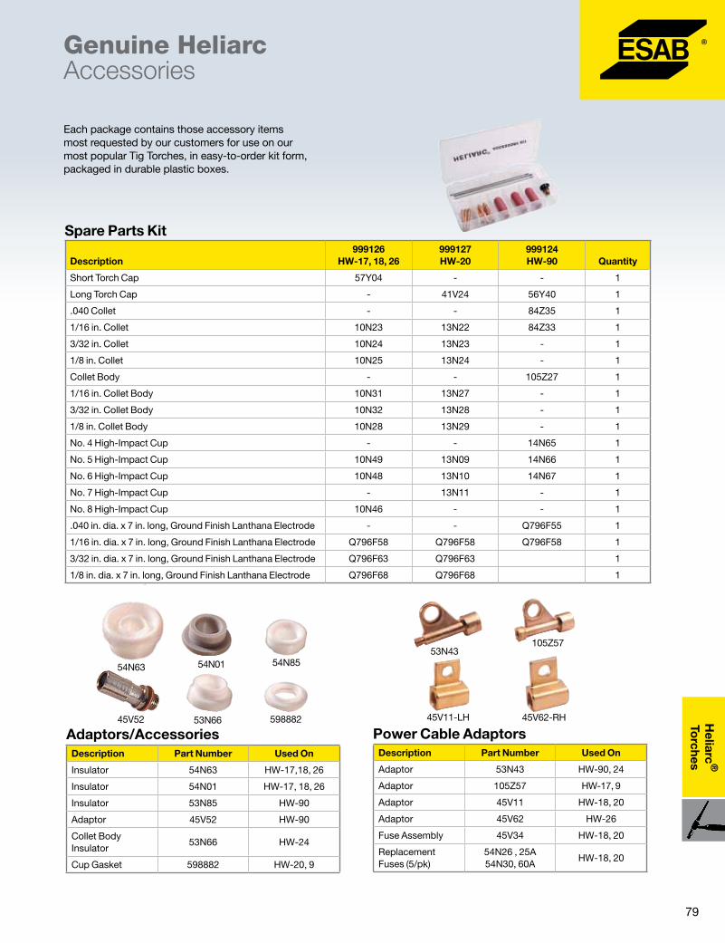
79
Heliarc
®
Torches
Each package contains those accessory items most requested by our customers for use on our most popular Tig Torches, in easy-to-order kit form, packaged in durable plastic boxes.
Genuine Heliarc Accessories
Description999126
HW-17, 18, 26999127 HW-20
999124 HW-90 Quantity
Short Torch Cap 57Y04 - - 1
Long Torch Cap - 41V24 56Y40 1
.040 Collet - - 84Z35 1
1/16 in. Collet 10N23 13N22 84Z33 1
3/32 in. Collet 10N24 13N23 - 1
1/8 in. Collet 10N25 13N24 - 1
Collet Body - - 105Z27 1
1/16 in. Collet Body 10N31 13N27 - 1
3/32 in. Collet Body 10N32 13N28 - 1
1/8 in. Collet Body 10N28 13N29 - 1
No. 4 High-Impact Cup - - 14N65 1
No. 5 High-Impact Cup 10N49 13N09 14N66 1
No. 6 High-Impact Cup 10N48 13N10 14N67 1
No. 7 High-Impact Cup - 13N11 - 1
No. 8 High-Impact Cup 10N46 - - 1
.040 in. dia. x 7 in. long, Ground Finish Lanthana Electrode - - Q796F55 1
1/16 in. dia. x 7 in. long, Ground Finish Lanthana Electrode Q796F58 Q796F58 Q796F58 1
3/32 in. dia. x 7 in. long, Ground Finish Lanthana Electrode Q796F63 Q796F63 1
1/8 in. dia. x 7 in. long, Ground Finish Lanthana Electrode Q796F68 Q796F68 1
54N63
53N66 598882
54N8554N01
45V52
Description Part Number Used On
Insulator 54N63 HW-17,18, 26
Insulator 54N01 HW-17, 18, 26
Insulator 53N85 HW-90
Adaptor 45V52 HW-90
Collet Body Insulator
53N66 HW-24
Cup Gasket 598882 HW-20, 9
Adaptors/Accessories45V11-LH 45V62-RH
53N43105Z57
Description Part Number Used On
Adaptor 53N43 HW-90, 24
Adaptor 105Z57 HW-17, 9
Adaptor 45V11 HW-18, 20
Adaptor 45V62 HW-26
Fuse Assembly 45V34 HW-18, 20
Replacement Fuses (5/pk)
54N26 , 25A 54N30, 60A
HW-18, 20
Power Cable Adaptors
Spare Parts Kit

80
Hel
iarc
®
Torc
hes
Only the more popular tungsten electrodes are listed. We carry a wide variety of electrodes. For ordering information consult your ESAB Genuine Heliarc® supplier. Each package contains ten electrodes. For additional accessories, consult the Genuine Heliarc® Torch Guide - ARC-23110
Genuine Heliarc Accessories
Diameter (in.)
Length (in.)
Pure (EWP)
Green Coded
1% Thoriated (EWTh-1)
Yellow Coded
2% Thoriated (EWTh-2)
Red Coded
Zirconiated (EWZr-1)
Brown Coded
2% Ceriated (EWCe-2)
Orange Coded
1 1/2% Lanthana (EWG)
Gray Coded
.020 7 (175mm) –– –– –– –– –– 796F53
.040 7 (175mm) 79Z15 –– 84Z18 –– –– Q796F55
1/16 3 (75mm) –– –– –– –– –– ––
6 (150mm) –– –– –– –– –– ––
7 (175mm) Q76Z51 Q84Z23 Q84Z19 790F47 Q798F92 796F58
3/32 3 (75mm) –– –– Q798F08 –– –– ––
6 (150mm) –– –– –– –– –– ––
7 (175mm) Q76Z57 –– Q84Z20 Q790F48 Q798F93 Q796F63
1/8 3 (75mm) –– –– Q798F12 –– –– Q796F66
6 (150mm) –– –– –– –– –– ––
7 (175mm) Q76Z52 Q84Z25 Q81Z79 Q790F49 Q798F94 Q796F68
5/32 6 (150mm) –– –– –– –– –– ––
7 (175mm) Q81Z43 –– Q81Z80 Q790F50 Q798F95 Q796F84
3/16 7 (175mm) –– –– 86Z05 Q790F51 (5) Q799F86 (5) 796F89
12 (300mm) –– –– Q798F22 (5) –– –– ––
1/4 7 (175mm) 76Z54 (5) –– 84Z21 (5) –– –– ––
Electrodes - Ground Finish Provides Maximum Smoothness
Description Part Number Used On
Zippered Nylon
12 1/2 ft. x 3" wide 35453 all
25 ft. x 3" wide 35454 all
Non-Zippered
9 ft. x 7/8" I.D. 2075198 HW-20
20 ft. x 7/8" I.D. 2075200
9 ft. x 1 1/4" I.D. 2075199 HW-18
10 ft. Leather with snaps 6" wide
20812
* Widths are as flat
Hoses/Cable Sheaths34015
57Y04
57Y02
84Z31
56Y40
41V35
41V24
41V33
Description Part Number Used On
Short Cap 41V33 HW-20, 9
Medium Cap 41V35 HW-20, 9
Long Cap 41V24 HW-20, 9
Long Cap 57Y02 HW-17, 18, 26
Medium Cap 34015 HW-17, 18, 26
Short Cap 57Y04 HW-17, 18, 26
Short Cap 84Z31 HW-90
Long Cap 56Y40 HW-90
Back Caps
81Product Data Page .................................................... ARC-23194
Accesso
ries
Remote Controls
MTA1 CAN � CAN based multi function remote control for the control panels A2, A4, T4, T6, M2, MA4, MA6, U6 and AristoPendant U8.
MTA1 CAN ..................................................................0459491880
M1 10Prog CAN � CAN based Synergic MIG for control panel MA6, U6 and AristoPendant U8
�MMA/TIG: Memory 1-10 and voltage trim =/-
M1 10Prog CAN ........................................................0459491882
AT1 CAN � CAN based standard MMA and TIG for control panel A2, A4, T4, and T6.
�MMA/TIG: Current control
AT1 CAN ...................................................................0459491883
AT1 Coarse/Fine CAN � CAN based standard MMA and TIG for control panel A2, A4, T4, and T6.
�MMA/TIG: Current control, coarse/fine
AT1 Coarse/Fine CAN ..............................................0459491884
M1 � Analogue standard MIG for control panel M10, M12, M13, M13i and M14
�MMA/TIG: Wire feed and voltage control
M1 ..............................................................................0459491895
AT1 Coarse � Analogue standard MMA and TIG for power sources with remote outlet
�MMA/TIG: Current control
AT1 Coarse ................................................................0459491896
AT1 Coarse/Fine � Analogue standard MMA and TIG for power sources with remote outlet
�MMA/TIG: Current control, coarse/fine
AT1 Coarse ................................................................0459491897
Remote Adapters for CAN Based Systems
� For analog MMA and TIG remote controls. For analog MIG/MAG remote controls and 3-step program switch RS3
RA 12 for MMA and TIG ............................................0459491910RA T1 TIG remote torch 12 pole* ...................................................................0459491912 10 pole* ...................................................................0459491913*includes holder and cable
Process Knob 1 Knob 2
MMA Current control Arc force
TIG Pulse current Background current
MIG/MAG 1 Wire feed speed Voltage control
MIG/MAG 2 Wire feed speed Voltage trim +⁄-

82
Acc
esso
ries
Remote Controls
Foot Control - TIG � Complete with 5 m rubber cable and equipped with 12-pole Burndy
FS002 analog ............................................................. 0349090886T1 CAN for Caddy Tig ............................................... 0460315880
Interconnection Cables 10 pole Interconnection Cables 12 pole
Remote-Control MMA1 �MMA 1 is equipped with 1 potentiometers for current setting.
� Includes 10 m rubber cable equipped with a 12-pole Burndy and a metal hook
MMA1 ......................................................................... 0349501024
MTA
1
CA
N
M 1
10 P
rog
C
AN
AT
1 C
AN
AT
1 C
oar
se
Fine
CA
N
M1
AT
1
Co
arse
AT
1 C
oar
se
Fine
Foo
t C
ont
rol T
IG
FS00
2
MM
A1
DTF x x x x
DTE/DTG x x x x
LHF x x x
LHN x x x
LTN/LTR x x x x
CaddyArc x x x
CaddyTig x x x x
ESABFeed x
MEK x
AristoFeed x x
AristoArc x x x
Aristo Tig x x x
AristoMig U x x x x
Size Part Number
0.25 m 0459960883
5 m 0459960880
10 m 0459960881
15 m NA
25 m 0459960882
5 m HD 0459960880
10 m HD 0459960881
25 m HD 0459960882
Size Part Number
0.25 m CAN 0459554884
5 m CAN 0459554880
10 m CAN 0459554881
15 m CAN 0459554882
20 m CAN 0459554883
5 m ANALOG 23 p 0459553880
5 m ANALOG 12 p 0459552880
10 m ANALOG 12 p 0459552881
15 m ANALOG 12 p 0459552882
25 m ANALOG 12 p 0459552883
83
Accesso
ries
General Accessories
Remote Controls � For use on 350mpi, SVI 450i, 353cv*, 453cv*, 453cc*, 553cc*, MP 460, 653cvcc*, Heliarc 252 and Heliarc 352
HC-3B Hand Pendant Control 30 ft. (9.1m) cable. Provides remote control of process switch (cv/cc), contactor switch (on/off) and output control (cc-amps/cv-volts) ...............................................................33838TC-2B Torch Control25 ft. (7.5 m) cable. Attach to torch handle. Provides remote current control and contactor (on/off) control .....................33839TC-3A Remote Torch Switch30 ft. (9.1 m) cable. Provides on/off contactor control. Includes push button switch and rubber boot to secure switch to torch handle. HW-9, 17, 20, 20A / 24 ......................................................35783 HW-18 / 26R ......................................................................36680FC-5C Foot Control30 ft. (9.1 m) cable. Provides remote current control and contactor (on/off) control ...........................................0558004234FC-5B EHD Foot Control30 ft. (9.1 m) cable. Extra Heavy Duty foot control provides remote current control and contactor (on/off) control ........33841
* Requires remote control kit .....................................0558001436
Truck Kits and Carts � Allows for easy mobility of equipment
TR-29 (two cylinder) for ESAB 353cv, 453cv, MP 460, 453cc, 553cc and 653cvcc, Heliarc 252, Heliarc 352 .....................37924TR-23A (two cylinder) for Heliarc 252 and Heliarc 352 .......36224Inverter Cart, (two cylinder) for use with MTS-3500i .........31700
R-33 Regulator / Flowmeter � Regulator with Lexan flow tube, 3000 psi cylinder gauge
R-33-FM-580* - Argon/Argon mixes, 10-50 cfh flow .........21557
R-33-RM-580HB* - Argon/Argon mixes, 10-50 cfh flow, for gas hses needing a "B" fitting added ...............................0558005172R-33-FM-320* - CO2, 10-65 cfh flow ..................................21558*Refer to Gas section for details
Hoses/FittingsGas Hose Assemblies 3 ft. (0.9 m) .........................................................................31504 6 ft. (1.8 m) .........................................................................31503 12 1⁄2 ft. (3.8 m) ...................................................................40V77 25 ft. (7.5 m) .......................................................................34V38 12 1⁄2 ft. (3.8 m) heavy duty (CO2) .......................................19416 25 ft. (7.5 m) heavy duty (CO2) ..........................................19415Gas Hose Coupler ............................................................. 11N17Gas Hose Coupler, “Y” ....................................................950356Water Hose Assemblies 3 ft. (0.8 m) .........................................................................20634 6 ft. (1.8 m) .........................................................................20633 12 1/2 ft. (3.8 m) .................................................................40V76 25 ft. (7.5 m) .....................................................................406196Water Hose Coupler ........................................................ 11N181 Gallon Torch Coolant ....................................................156F05
Twist Lock Connectors � For use on MTS-3500i, Heliarc 252, Heliarc 352, Heliarc 161 AC/DC, Migmaster 275, CaddyArc 151i, CaddyArc 201i, CaddyTig 2200i, CaddyTig 2200i AC/DC, MultiMaster 160 / 260, MultiMaster 300, Origo Mig 4002c/5002c/6502c, Aristo 5000i, U5000i, Origo Mig 320/410/510, Origo Arc 410c/650c.
50 mm ConnectorsQuick-acting twist lock connectors for attaching output power cables or torches to power source: Male for 1/0 to 4/0 cable .............................................13792513 Female for 1/0 to 4/0 cable .........................................13735631 Male for #2 AWG to 1/0 cable .....................................13733936 Female for #2 AWG to 1/0 cable ....................................... 13735632 Quick connector with 1⁄2 in. threaded stud ..................13735501 Tee connector (1 male, 2 female) ........................................13792804
FC-5B EHDFC-5C Foot Control

84
Acc
esso
ries
Ground Clamps � ESAB Ground clamps provide the largest workpiece-contact area of any clamp on the market. They assure positive connections and slide easily under steel plate. Ground clamps help eliminate arc blow, make it easy to change ground location, and assure proper voltage for maximum weld results with all rods.
General Accessories
Work/Electrode Holder Cable AssembliesIncludes twist lock 25mm QC plug 10 ft. Cable Kit, electrode/work cable assemblies, 150A ....................................................0349501078 10 ft. Electrode holder cable assembly, 150A ........0349501079Includes twist lock 50mm QC plug 10 ft. Work cable*, #3AWG .......................................0700006901 15 ft. Work cable*, 2/0AWG ................................................ 36253 15 ft. Work cable*, 2/0AWG ................................................ 35881 15 ft. Electrode holder 2/0AWG .......................................... 21226Includes 1⁄2" ring lug 15 ft. Work cable*, 2/0AWG ......................................0558001440 * work cables include work clamp
Cable Connectors � ESAB Cable Connectors offers many advantages over older styles. Metal parts are precision machined from heavy, specially shaped brass extrusion. Cam action design of male half connector pulls the two halves tightly together. Connector covers are molded from a special heat and cold resistant material. Covers have no metal liner to rust or corrode. Easily installed with a 1⁄4 in. Allen wrench.
Feeder Cable Assemblies1⁄2” Ring lug to 1/2” Ring lug 15 ft. Feeder cable, 2/0AWG .................................... 05580014411⁄2” Ring lug to 50mm QC 15 ft. Feeder cable, 2/0AWG ...............................................36254
Electrode Holder � Curved upper lever with low angle design for better hold. Firm electrode grip, fully insulated, high strength spring. High leverage tong designed for easy opening. Heavy-duty shockproof handle.
Male Half Cover Removed
Female Half Cover Removed
Female Brass Connector Is Recessed - No Accidental Short
▼▼
Cam Type Action Here Makes Positive Stop/Lock
This Plug Fits Female Half No. LC-40 Connector
LC-1040
▲
Tight Fit Here — Face to Face Contact
Model “G”
Model EG-500
Model 500
▲
▼
5”
Model MIG-600
ModelPart
NumberAmp
CapacityType Cable Connection Weight
200 81F11 200 Mechanical Oval-
Point Screw13 oz.
300 81F12 300 Mechanical Oval-
Point Screw26 oz.
500 81F13 500 Mechanical Oval-
Point Screw35 oz.
MIG-600 0160288001 600 Two Oval-Point
Screws 56 oz.
G 82F17 600 Two Oval-Point
Screws 52 oz.
EG-500 82F32 500 Bolt and Nut with
Support22 oz.
EG-300 82F31 300 Bolt and Nut with
Support11 oz.
ModelPart
NumberCable
ConnectionCable
Capacity WeightStd
Pack
LC-40 81F25 Oval-Point Screw Mech.
1/0 thru 3/0
17 oz. 1
Same connector style as above - only one half of the set
LC-40 81F26 Male half 1/0 thru 3/0
LC-40 81F27 Female half 1/0 thru 3/0
Part Number
Amp Capacity
Electrode Capacity
Cable Capacity Length Weight
81F02 300 Up to 7⁄32 in. 2/0 10 in. 20 oz.
0558008634 500 Up to 3⁄8 in. 4/0 11 in. 26 oz.

Inside every great welder is a warrior.
ESAB Welding & Cutting Products / esabna.com / 1.800.ESAB.123
Introducing Weld Warrior™ personal protection equipment. Because you don’t
just finish the job – you conquer it. Order the catalog (PPE-1010) to check out the entire line of gear or visit us online at esabna.com/weldwarrior today.
Find us facebook.com/esabna twitter.com/esabna youtube.com/esabweb
AR
C-23000D
08/12
The ESAB group is certified
according to ISO 14001 &
OHSAS 18001
Unrivaled service and support.Every ESAB product is backed by our commitment to superior customer service and support. Our skilled customer service department is prepared to quickly answer any questions, address problems, and help with maintenance and upgrading of your equipment. Our products are backed with the most comprehensive warranty in the business.
With ESAB, you can be sure that you have purchased equipment that will meet your needs today and in the future. Product and process training is also available. Ask your ESAB sales representative or distributor for a complete ESAB solution.
NOTICE:Test results described above were obtained under controlled laboratory conditions, and are not guarantees for use in the field. Actual use of the product may produce varying results due to conditions and welding techniques over which ESAB has no control, including but not limited to plate chemistry, weldment design, fabrication methods, wire size, welding procedure, service requirements and the environment. The User should confirm by qualification testing, or other appropriate means, the suitability of any welding consumable and procedure before use in the intended application.
CAUTION:Users should be thoroughly familiar with the safety precautions referenced in the product label for the relevant product and the Safety Data Sheet for the product. Safety Data Sheets are available at www,esabna.com or by calling 1-800-ESAB-123.
usA: P.O. Box 100545, 411 South Ebenezer Road, Florence, SC 29501-0545Canada: 6010 Tomken Road, Mississauga, Ontario L5T-1X9Mexico: Ave. Diego Díaz de Berlanga, No. 130, Col. Nogalar San Nicolás de los Garza N.L. CP 66480 Monterrey, Mexico
EsAB Welding & Cutting Products / esabna.com / 1.800.EsAB.123