Arc Welding Power Source - Norco Medical · Arc Welding Power Source Syncrowave 200 Visit our...
56
OM-225 389K 2008-12 Processes Description TIG (GTAW) Welding Stick (SMAW) Welding Arc Welding Power Source Syncrowave 200 R Visit our website at www.MillerWelds.com File: TIG (GTAW) ESPAÑOL FRANÇAIS ENGLISH
Transcript of Arc Welding Power Source - Norco Medical · Arc Welding Power Source Syncrowave 200 Visit our...

OM-225 389K2008−12
Processes
Description
TIG (GTAW) Welding
Stick (SMAW) Welding
Arc Welding Power Source
Syncrowave 200�
Visit our website at
www.MillerWelds.com
File: TIG (GTAW)
ES
PAÑ
OL
FR
AN
ÇA
ISE
NG
LIS
H

Miller Electric manufactures a full lineof welders and welding related equipment.For information on other quality Millerproducts, contact your local Miller distributor to receive the latest fullline catalog or individual specification sheets. To locate your nearestdistributor or service agency call 1-800-4-A-Miller, or visit us atwww.MillerWelds.com on the web.
Thank you and congratulations on choosing Miller. Now you can getthe job done and get it done right. We know you don’t have time to doit any other way.
That’s why when Niels Miller first started building arc welders in 1929,he made sure his products offered long-lasting value and superiorquality. Like you, his customers couldn’t afford anything less. Millerproducts had to be more than the best they could be. They had to be thebest you could buy.
Today, the people that build and sell Miller products continue thetradition. They’re just as committed to providing equipment and servicethat meets the high standards of quality and value established in 1929.
This Owner’s Manual is designed to help you get the most out of yourMiller products. Please take time to read the Safety precautions. Theywill help you protect yourself against potential hazards on the worksite.
We’ve made installation and operation quickand easy. With Miller you can count on yearsof reliable service with proper maintenance.And if for some reason the unit needs repair,there’s a Troubleshooting section that willhelp you figure out what the problem is. Theparts list will then help you to decide theexact part you may need to fix the problem.Warranty and service information for yourparticular model are also provided.
Miller is the first weldingequipment manufacturer inthe U.S.A. to be registered tothe ISO 9001:2000 QualitySystem Standard.
Working as hard as you do− every power source fromMiller is backed by the mosthassle-free warranty in thebusiness.
From Miller to You
Mil_Thank 4/05

TABLE OF CONTENTS
SECTION 1 − SAFETY PRECAUTIONS - READ BEFORE USING 1. . . . . . . . . . . . . . . . . . . . . . . . . . . . . . . . . . . 1-1. Symbol Usage 1. . . . . . . . . . . . . . . . . . . . . . . . . . . . . . . . . . . . . . . . . . . . . . . . . . . . . . . . . . . . . . . . . . . . . . . .
1-2. Arc Welding Hazards 1. . . . . . . . . . . . . . . . . . . . . . . . . . . . . . . . . . . . . . . . . . . . . . . . . . . . . . . . . . . . . . . . . .
1-3. Additional Symbols For Installation, Operation, And Maintenance 3. . . . . . . . . . . . . . . . . . . . . . . . . . . . .
1-4. California Proposition 65 Warnings 4. . . . . . . . . . . . . . . . . . . . . . . . . . . . . . . . . . . . . . . . . . . . . . . . . . . . . . . 1-5. Principal Safety Standards 4. . . . . . . . . . . . . . . . . . . . . . . . . . . . . . . . . . . . . . . . . . . . . . . . . . . . . . . . . . . . .
1-6. EMF Information 4. . . . . . . . . . . . . . . . . . . . . . . . . . . . . . . . . . . . . . . . . . . . . . . . . . . . . . . . . . . . . . . . . . . . . .
SECTION 2 − INSTALLATION 5. . . . . . . . . . . . . . . . . . . . . . . . . . . . . . . . . . . . . . . . . . . . . . . . . . . . . . . . . . . . . . . . . . 2-1. Included with Your Unit 5. . . . . . . . . . . . . . . . . . . . . . . . . . . . . . . . . . . . . . . . . . . . . . . . . . . . . . . . . . . . . . . . .
2-2. Selecting A Location 5. . . . . . . . . . . . . . . . . . . . . . . . . . . . . . . . . . . . . . . . . . . . . . . . . . . . . . . . . . . . . . . . . . .
2-3. Dimensions And Weights 6. . . . . . . . . . . . . . . . . . . . . . . . . . . . . . . . . . . . . . . . . . . . . . . . . . . . . . . . . . . . . . . 2-4. Serial Number And Rating Label Location 6. . . . . . . . . . . . . . . . . . . . . . . . . . . . . . . . . . . . . . . . . . . . . . . . .
2-5. Specifications 6. . . . . . . . . . . . . . . . . . . . . . . . . . . . . . . . . . . . . . . . . . . . . . . . . . . . . . . . . . . . . . . . . . . . . . . .
2-6. Duty Cycle Chart 7. . . . . . . . . . . . . . . . . . . . . . . . . . . . . . . . . . . . . . . . . . . . . . . . . . . . . . . . . . . . . . . . . . . . .
2-7. DC Volt-Ampere Curves 7. . . . . . . . . . . . . . . . . . . . . . . . . . . . . . . . . . . . . . . . . . . . . . . . . . . . . . . . . . . . . . . .
2-8. AC Volt-Ampere Curves 8. . . . . . . . . . . . . . . . . . . . . . . . . . . . . . . . . . . . . . . . . . . . . . . . . . . . . . . . . . . . . . . . 2-9. Weld Output Terminals And Selecting Cable Sizes 9. . . . . . . . . . . . . . . . . . . . . . . . . . . . . . . . . . . . . . . . . .
2-10. Remote 14 Receptacle 9. . . . . . . . . . . . . . . . . . . . . . . . . . . . . . . . . . . . . . . . . . . . . . . . . . . . . . . . . . . . . . . . .
2-11. 115 Volts AC Duplex Receptacle And Supplementary Protector CB1 10. . . . . . . . . . . . . . . . . . . . . . . . . .
2-12. Shielding Gas Connections 10. . . . . . . . . . . . . . . . . . . . . . . . . . . . . . . . . . . . . . . . . . . . . . . . . . . . . . . . . . . . .
2-13. Typical TIG Connections 11. . . . . . . . . . . . . . . . . . . . . . . . . . . . . . . . . . . . . . . . . . . . . . . . . . . . . . . . . . . . . . . 2-14. Typical Stick Connections 12. . . . . . . . . . . . . . . . . . . . . . . . . . . . . . . . . . . . . . . . . . . . . . . . . . . . . . . . . . . . . .
2-15. Electrical Service Guide 12. . . . . . . . . . . . . . . . . . . . . . . . . . . . . . . . . . . . . . . . . . . . . . . . . . . . . . . . . . . . . . . .
2-16. Connecting Input Power In 208-230 Volt Models 13. . . . . . . . . . . . . . . . . . . . . . . . . . . . . . . . . . . . . . . . . . . .
2-17. Connecting Input Power In 460/575 Volt Models 13. . . . . . . . . . . . . . . . . . . . . . . . . . . . . . . . . . . . . . . . . . . .
SECTION 3 − OPERATION 15. . . . . . . . . . . . . . . . . . . . . . . . . . . . . . . . . . . . . . . . . . . . . . . . . . . . . . . . . . . . . . . . . . . . 3-1. Controls 15. . . . . . . . . . . . . . . . . . . . . . . . . . . . . . . . . . . . . . . . . . . . . . . . . . . . . . . . . . . . . . . . . . . . . . . . . . . . .
3-2. Ammeter, Voltmeter And Parameter Display 16. . . . . . . . . . . . . . . . . . . . . . . . . . . . . . . . . . . . . . . . . . . . . . .
3-3. Amperage/Purge Control 16. . . . . . . . . . . . . . . . . . . . . . . . . . . . . . . . . . . . . . . . . . . . . . . . . . . . . . . . . . . . . . .
3-4. Process Control 16. . . . . . . . . . . . . . . . . . . . . . . . . . . . . . . . . . . . . . . . . . . . . . . . . . . . . . . . . . . . . . . . . . . . . .
3-5. Pulse Control 17. . . . . . . . . . . . . . . . . . . . . . . . . . . . . . . . . . . . . . . . . . . . . . . . . . . . . . . . . . . . . . . . . . . . . . . . .
3-6. Balance/DIG Control 18. . . . . . . . . . . . . . . . . . . . . . . . . . . . . . . . . . . . . . . . . . . . . . . . . . . . . . . . . . . . . . . . . . 3-7. Factory Parameter Defaults And Range And Resolution 19. . . . . . . . . . . . . . . . . . . . . . . . . . . . . . . . . . . . .
3-8. Postflow Control 20. . . . . . . . . . . . . . . . . . . . . . . . . . . . . . . . . . . . . . . . . . . . . . . . . . . . . . . . . . . . . . . . . . . . . .
3-9. Selecting Syncro Start Characteristics 21. . . . . . . . . . . . . . . . . . . . . . . . . . . . . . . . . . . . . . . . . . . . . . . . . . . .
3-10. Pulser Peak And Background 22. . . . . . . . . . . . . . . . . . . . . . . . . . . . . . . . . . . . . . . . . . . . . . . . . . . . . . . . . . .
3-11. Timer/Cycle Counter 23. . . . . . . . . . . . . . . . . . . . . . . . . . . . . . . . . . . . . . . . . . . . . . . . . . . . . . . . . . . . . . . . . . . 3-12. Software Number/Revision 24. . . . . . . . . . . . . . . . . . . . . . . . . . . . . . . . . . . . . . . . . . . . . . . . . . . . . . . . . . . . .
SECTION 4 − MAINTENANCE AND TROUBLESHOOTING 25. . . . . . . . . . . . . . . . . . . . . . . . . . . . . . . . . . . . . . . . 4-1. Routine Maintenance 25. . . . . . . . . . . . . . . . . . . . . . . . . . . . . . . . . . . . . . . . . . . . . . . . . . . . . . . . . . . . . . . . . .
4-2. Adjusting Spark Gaps 25. . . . . . . . . . . . . . . . . . . . . . . . . . . . . . . . . . . . . . . . . . . . . . . . . . . . . . . . . . . . . . . . .
4-3. Voltmeter/Ammeter Help Displays 26. . . . . . . . . . . . . . . . . . . . . . . . . . . . . . . . . . . . . . . . . . . . . . . . . . . . . . . 4-4. Troubleshooting 27. . . . . . . . . . . . . . . . . . . . . . . . . . . . . . . . . . . . . . . . . . . . . . . . . . . . . . . . . . . . . . . . . . . . . .
SECTION 5 − ELECTRICAL DIAGRAM 28. . . . . . . . . . . . . . . . . . . . . . . . . . . . . . . . . . . . . . . . . . . . . . . . . . . . . . . . . . SECTION 6 − HIGH FREQUENCY 30. . . . . . . . . . . . . . . . . . . . . . . . . . . . . . . . . . . . . . . . . . . . . . . . . . . . . . . . . . . . . .
6-1. Welding Processes Requiring High Frequency 30. . . . . . . . . . . . . . . . . . . . . . . . . . . . . . . . . . . . . . . . . . . . .
6-2. Incorrect Installation 30. . . . . . . . . . . . . . . . . . . . . . . . . . . . . . . . . . . . . . . . . . . . . . . . . . . . . . . . . . . . . . . . . . .
6-3. Correct Installation 31. . . . . . . . . . . . . . . . . . . . . . . . . . . . . . . . . . . . . . . . . . . . . . . . . . . . . . . . . . . . . . . . . . . . SECTION 7 − SELECTING AND PREPARING A TUNGSTEN FOR DC OR AC WELDING 32. . . . . . . . . . . . . .
7-1. Selecting Tungsten Electrode (Wear Clean gloves To Prevent Contamination Of Tungsten) 32. . . . . . . .
7-2. Preparing Tungsten Electrode For Welding With Phase Control Machines 32. . . . . . . . . . . . . . . . . . . . . .

TABLE OF CONTENTS
SECTION 8 − GUIDELINES FOR TIG WELDING (GTAW) 33. . . . . . . . . . . . . . . . . . . . . . . . . . . . . . . . . . . . . . . . . . 8-1. Positioning The Torch 33. . . . . . . . . . . . . . . . . . . . . . . . . . . . . . . . . . . . . . . . . . . . . . . . . . . . . . . . . . . . . . . . . . 8-2. Torch Movement During Welding 34. . . . . . . . . . . . . . . . . . . . . . . . . . . . . . . . . . . . . . . . . . . . . . . . . . . . . . . . 8-3. Positioning Torch Tungsten For Various Weld Joints 35. . . . . . . . . . . . . . . . . . . . . . . . . . . . . . . . . . . . . . . .
SECTION 9 − STICK WELDING (SMAW) GUIDELINES 36. . . . . . . . . . . . . . . . . . . . . . . . . . . . . . . . . . . . . . . . . . . . SECTION 10 − PARTS LIST 44. . . . . . . . . . . . . . . . . . . . . . . . . . . . . . . . . . . . . . . . . . . . . . . . . . . . . . . . . . . . . . . . . . . OPTIONS AND ACCESSORIESWARRANTY

OM-225 389 Page 1
SECTION 1 − SAFETY PRECAUTIONS - READ BEFORE USINGsom _2007−04
7
Protect yourself and others from injury — read and follow these precautions.
1-1. Symbol Usage
DANGER! − Indicates a hazardous situation which, ifnot avoided, will result in death or serious injury. Thepossible hazards are shown in the adjoining symbolsor explained in the text.
Indicates a hazardous situation which, if not avoided,could result in death or serious injury. The possiblehazards are shown in the adjoining symbols or ex-plained in the text.
NOTICE − Indicates statements not related to personal injury.
� Indicates special instructions.
This group of symbols means Warning! Watch Out! ELECTRICSHOCK, MOVING PARTS, and HOT PARTS hazards. Consult sym-bols and related instructions below for necessary actions to avoid thehazards.
1-2. Arc Welding Hazards
The symbols shown below are used throughout this manualto call attention to and identify possible hazards. When yousee the symbol, watch out, and follow the related instructionsto avoid the hazard. The safety information given below isonly a summary of the more complete safety informationfound in the Safety Standards listed in Section 1-5. Read andfollow all Safety Standards.
Only qualified persons should install, operate, maintain, andrepair this unit.
During operation, keep everybody, especially children, away.
ELECTRIC SHOCK can kill.
Touching live electrical parts can cause fatal shocksor severe burns. The electrode and work circuit iselectrically live whenever the output is on. The inputpower circuit and machine internal circuits are also
live when power is on. In semiautomatic or automatic wire welding, thewire, wire reel, drive roll housing, and all metal parts touching thewelding wire are electrically live. Incorrectly installed or improperlygrounded equipment is a hazard.
� Do not touch live electrical parts.� Wear dry, hole-free insulating gloves and body protection.� Insulate yourself from work and ground using dry insulating mats
or covers big enough to prevent any physical contact with the workor ground.
� Do not use AC output in damp areas, if movement is confined, or ifthere is a danger of falling.
� Use AC output ONLY if required for the welding process.� If AC output is required, use remote output control if present on
unit.� Additional safety precautions are required when any of the follow-
ing electrically hazardous conditions are present: in damplocations or while wearing wet clothing; on metal structures suchas floors, gratings, or scaffolds; when in cramped positions suchas sitting, kneeling, or lying; or when there is a high risk of unavoid-able or accidental contact with the workpiece or ground. For theseconditions, use the following equipment in order presented: 1) asemiautomatic DC constant voltage (wire) welder, 2) a DC manual(stick) welder, or 3) an AC welder with reduced open-circuit volt-age. In most situations, use of a DC, constant voltage wire welderis recommended. And, do not work alone!
� Disconnect input power or stop engine before installing orservicing this equipment. Lockout/tagout input power according toOSHA 29 CFR 1910.147 (see Safety Standards).
� Properly install and ground this equipment according to itsOwner’s Manual and national, state, and local codes.
� Always verify the supply ground − check and be sure that inputpower cord ground wire is properly connected to ground terminal indisconnect box or that cord plug is connected to a properlygrounded receptacle outlet.
� When making input connections, attach proper grounding conduc-tor first − double-check connections.
� Keep cords dry, free of oil and grease, and protected from hot metaland sparks.
� Frequently inspect input power cord for damage or bare wiring −replace cord immediately if damaged − bare wiring can kill.
� Turn off all equipment when not in use.
� Do not use worn, damaged, undersized, or poorly spliced cables.
� Do not drape cables over your body.
� If earth grounding of the workpiece is required, ground it directlywith a separate cable.
� Do not touch electrode if you are in contact with the work, ground,or another electrode from a different machine.
� Do not touch electrode holders connected to two welding ma-chines at the same time since double open-circuit voltage will bepresent.
� Use only well-maintained equipment. Repair or replace damagedparts at once. Maintain unit according to manual.
� Wear a safety harness if working above floor level.
� Keep all panels and covers securely in place.
� Clamp work cable with good metal-to-metal contact to workpieceor worktable as near the weld as practical.
� Insulate work clamp when not connected to workpiece to preventcontact with any metal object.
� Do not connect more than one electrode or work cable to anysingle weld output terminal.
SIGNIFICANT DC VOLTAGE exists in inverter-typewelding power sources after removal of inputpower.� Turn Off inverter, disconnect input power, and discharge input
capacitors according to instructions in Maintenance Sectionbefore touching any parts.
HOT PARTS can cause severe burns.
� Do not touch hot parts bare handed.� Allow cooling period before working on gun or
torch.� To handle hot parts, use proper tools and/or
wear heavy, insulated welding gloves andclothing to prevent burns.

OM-225 389 Page 2
Welding produces fumes and gases. Breathingthese fumes and gases can be hazardous to yourhealth.
FUMES AND GASES can be hazardous.
� Keep your head out of the fumes. Do not breathe the fumes.
� If inside, ventilate the area and/or use local forced ventilation at thearc to remove welding fumes and gases.
� If ventilation is poor, wear an approved air-supplied respirator.
� Read and understand the Material Safety Data Sheets (MSDSs)and the manufacturer’s instructions for metals, consumables,coatings, cleaners, and degreasers.
� Work in a confined space only if it is well ventilated, or whilewearing an air-supplied respirator. Always have a trained watch-person nearby. Welding fumes and gases can displace air andlower the oxygen level causing injury or death. Be sure the breath-ing air is safe.
� Do not weld in locations near degreasing, cleaning, or spraying op-erations. The heat and rays of the arc can react with vapors to formhighly toxic and irritating gases.
� Do not weld on coated metals, such as galvanized, lead, orcadmium plated steel, unless the coating is removed from the weldarea, the area is well ventilated, and while wearing an air-suppliedrespirator. The coatings and any metals containing these elementscan give off toxic fumes if welded.
Arc rays from the welding process produce intensevisible and invisible (ultraviolet and infrared) raysthat can burn eyes and skin. Sparks fly off from theweld.
ARC RAYS can burn eyes and skin.
� Wear an approved welding helmet fitted with a proper shade of fil-ter lenses to protect your face and eyes when welding or watching(see ANSI Z49.1 and Z87.1 listed in Safety Standards).
� Wear approved safety glasses with side shields under yourhelmet.
� Use protective screens or barriers to protect others from flash,glare and sparks; warn others not to watch the arc.
� Wear protective clothing made from durable, flame-resistant mate-rial (leather, heavy cotton, or wool) and foot protection.
Welding on closed containers, such as tanks,drums, or pipes, can cause them to blow up. Sparkscan fly off from the welding arc. The flying sparks, hotworkpiece, and hot equipment can cause fires and
burns. Accidental contact of electrode to metal objects can causesparks, explosion, overheating, or fire. Check and be sure the area issafe before doing any welding.
WELDING can cause fire or explosion.
� Remove all flammables within 35 ft (10.7 m) of the welding arc. Ifthis is not possible, tightly cover them with approved covers.
� Do not weld where flying sparks can strike flammable material.
� Protect yourself and others from flying sparks and hot metal.
� Be alert that welding sparks and hot materials from welding caneasily go through small cracks and openings to adjacent areas.
� Watch for fire, and keep a fire extinguisher nearby.
� Be aware that welding on a ceiling, floor, bulkhead, or partition cancause fire on the hidden side.
� Do not weld on closed containers such as tanks, drums, or pipes,unless they are properly prepared according to AWS F4.1 (seeSafety Standards).
� Do not weld where the atmosphere may contain flammable dust,gas, or liquid vapors (such as gasoline).
� Connect work cable to the work as close to the welding area aspractical to prevent welding current from traveling long, possiblyunknown paths and causing electric shock, sparks, and firehazards.
� Do not use welder to thaw frozen pipes.� Remove stick electrode from holder or cut off welding wire at
contact tip when not in use.� Wear oil-free protective garments such as leather gloves, heavy
shirt, cuffless trousers, high shoes, and a cap.� Remove any combustibles, such as a butane lighter or matches,
from your person before doing any welding.� After completion of work, inspect area to ensure it is free of sparks,
glowing embers, and flames.� Use only correct fuses or circuit breakers. Do not oversize or by-
pass them.� Follow requirements in OSHA 1910.252 (a) (2) (iv) and NFPA 51B
for hot work and have a fire watcher and extinguisher nearby.
FLYING METAL or DIRT can injure eyes.
� Welding, chipping, wire brushing, and grindingcause sparks and flying metal. As welds cool,they can throw off slag.
� Wear approved safety glasses with sideshields even under your welding helmet.
BUILDUP OF GAS can injure or kill.
� Shut off shielding gas supply when not in use.� Always ventilate confined spaces or use
approved air-supplied respirator.
MAGNETIC FIELDS can affect ImplantedMedical Devices.
� Wearers of Pacemakers and other ImplantedMedical Devices should keep away.
� Implanted Medical Device wearers should consult their doctorand the device manufacturer before going near arc welding, spotwelding, gouging, plasma arc cutting, or induction heatingoperations.
NOISE can damage hearing.
Noise from some processes or equipment candamage hearing.
� Wear approved ear protection if noise level ishigh.
Shielding gas cylinders contain gas under highpressure. If damaged, a cylinder can explode. Sincegas cylinders are normally part of the weldingprocess, be sure to treat them carefully.
CYLINDERS can explode if damaged.
� Protect compressed gas cylinders from excessive heat, mechani-cal shocks, physical damage, slag, open flames, sparks, and arcs.
� Install cylinders in an upright position by securing to a stationarysupport or cylinder rack to prevent falling or tipping.
� Keep cylinders away from any welding or other electrical circuits.� Never drape a welding torch over a gas cylinder.� Never allow a welding electrode to touch any cylinder.� Never weld on a pressurized cylinder − explosion will result.� Use only correct shielding gas cylinders, regulators, hoses, and fit-
tings designed for the specific application; maintain them andassociated parts in good condition.
� Turn face away from valve outlet when opening cylinder valve.� Keep protective cap in place over valve except when cylinder is in
use or connected for use.� Use the right equipment, correct procedures, and sufficient num-
ber of persons to lift and move cylinders.� Read and follow instructions on compressed gas cylinders,
associated equipment, and Compressed Gas Association (CGA)publication P-1 listed in Safety Standards.

OM-225 389 Page 3
1-3. Additional Symbols For Installation, Operation, And Maintenance
FIRE OR EXPLOSION hazard.
� Do not install or place unit on, over, or nearcombustible surfaces.
� Do not install unit near flammables.
� Do not overload building wiring − be sure power supply system isproperly sized, rated, and protected to handle this unit.
FALLING UNIT can cause injury.
� Use lifting eye to lift unit only, NOT runninggear, gas cylinders, or any other accessories.
� Use equipment of adequate capacity to lift andsupport unit.
� If using lift forks to move unit, be sure forks arelong enough to extend beyond opposite side ofunit.
OVERUSE can cause OVERHEATING
� Allow cooling period; follow rated duty cycle.� Reduce current or reduce duty cycle before
starting to weld again.� Do not block or filter airflow to unit.
FLYING SPARKS can cause injury.
� Wear a face shield to protect eyes and face.� Shape tungsten electrode only on grinder with
proper guards in a safe location wearing properface, hand, and body protection.
� Sparks can cause fires — keep flammables away.
STATIC (ESD) can damage PC boards.
� Put on grounded wrist strap BEFORE handlingboards or parts.
� Use proper static-proof bags and boxes tostore, move, or ship PC boards.
MOVING PARTS can cause injury.
� Keep away from moving parts.� Keep away from pinch points such as drive
rolls.
WELDING WIRE can cause injury.
� Do not press gun trigger until instructed to doso.
� Do not point gun toward any part of the body,other people, or any metal when threadingwelding wire.
MOVING PARTS can cause injury.
� Keep away from moving parts such as fans.� Keep all doors, panels, covers, and guards
closed and securely in place.
� Have only qualified persons remove doors, panels, covers, orguards for maintenance as necessary.
� Reinstall doors, panels, covers, or guards when maintenance isfinished and before reconnecting input power.
READ INSTRUCTIONS.
� Read Owner’s Manual before using or servic-ing unit.
� Use only genuine replacement parts from themanufacturer.
H.F. RADIATION can cause interference.
� High-frequency (H.F.) can interfere with radionavigation, safety services, computers, andcommunications equipment.
� Have only qualified persons familiar withelectronic equipment perform this installation.
� The user is responsible for having a qualified electrician prompt-ly correct any interference problem resulting from the installa-tion.
� If notified by the FCC about interference, stop using theequipment at once.
� Have the installation regularly checked and maintained.
� Keep high-frequency source doors and panels tightly shut, keepspark gaps at correct setting, and use grounding and shielding tominimize the possibility of interference.
ARC WELDING can cause interference.
� Electromagnetic energy can interfere withsensitive electronic equipment such ascomputers and computer-driven equipmentsuch as robots.
� Be sure all equipment in the welding area iselectromagnetically compatible.
� To reduce possible interference, keep weld cables as short aspossible, close together, and down low, such as on the floor.
� Locate welding operation 100 meters from any sensitive elec-tronic equipment.
� Be sure this welding machine is installed and groundedaccording to this manual.
� If interference still occurs, the user must take extra measuressuch as moving the welding machine, using shielded cables,using line filters, or shielding the work area.

OM-225 389 Page 4
1-4. California Proposition 65 Warnings
Welding or cutting equipment produces fumes or gaseswhich contain chemicals known to the State of California tocause birth defects and, in some cases, cancer. (CaliforniaHealth & Safety Code Section 25249.5 et seq.)
Battery posts, terminals and related accessories contain leadand lead compounds, chemicals known to the State ofCalifornia to cause cancer and birth defects or otherreproductive harm. Wash hands after handling.
For Gasoline Engines:
Engine exhaust contains chemicals known to the State ofCalifornia to cause cancer, birth defects, or other reproduc-tive harm.
For Diesel Engines:
Diesel engine exhaust and some of its constituents areknown to the State of California to cause cancer, birthdefects, and other reproductive harm.
1-5. Principal Safety Standards
Safety in Welding, Cutting, and Allied Processes, ANSI Standard Z49.1,from Global Engineering Documents (phone: 1-877-413-5184, website:www.global.ihs.com).
Recommended Safe Practices for the Preparation for Welding and Cut-ting of Containers and Piping, American Welding Society StandardAWS F4.1, from Global Engineering Documents (phone:1-877-413-5184, website: www.global.ihs.com).
National Electrical Code, NFPA Standard 70, from National Fire Protec-tion Association, P.O. Box 9101, Quincy, MA 02269-9101 (phone:617-770-3000, website: www.nfpa.org and www. sparky.org).
Safe Handling of Compressed Gases in Cylinders, CGA Pamphlet P-1,from Compressed Gas Association, 4221 Walney Road, 5th Floor,Chantilly, VA 20151 (phone: 703-788-2700, website:www.cganet.com).
Code for Safety in Welding and Cutting, CSA Standard W117.2, fromCanadian Standards Association, Standards Sales, 5060 Mississauga,
Ontario, Canada L4W 5NS (phone: 800-463-6727 or in Toronto416-747-4044, website: www.csa-international.org).Safe Practice For Occupational And Educational Eye And Face Protec-tion, ANSI Standard Z87.1, from American National Standards Institute,25 West 43rd Street, New York, NY 10036–8002 (phone:212-642-4900, website: www.ansi.org).Standard for Fire Prevention During Welding, Cutting, and Other HotWork, NFPA Standard 51B, from National Fire Protection Association,P.O. Box 9101, Quincy, MA 02269-9101 (phone: 617-770-3000, web-site: www.nfpa.org.OSHA, Occupational Safety and Health Standards for General Indus-try, Title 29, Code of Federal Regulations (CFR), Part 1910, Subpart Q,and Part 1926, Subpart J, from U.S. Government Printing Office, Super-intendent of Documents, P.O. Box 371954, Pittsburgh, PA 15250-7954(phone: 1-866-512-1800) (there are 10 Regional Offices—phone forRegion 5, Chicago, is 312-353-2220, website: www.osha.gov).
1-6. EMF Information
Considerations About Welding And The Effects Of Low FrequencyElectric And Magnetic Fields
Welding current, as it flows through welding cables, will cause electro-magnetic fields. There has been and still is some concern about suchfields. However, after examining more than 500 studies spanning 17years of research, a special blue ribbon committee of the NationalResearch Council concluded that: “The body of evidence, in thecommittee’s judgment, has not demonstrated that exposure to power-frequency electric and magnetic fields is a human-health hazard.”However, studies are still going forth and evidence continues to beexamined. Until the final conclusions of the research are reached, youmay wish to minimize your exposure to electromagnetic fields whenwelding or cutting.
To reduce magnetic fields in the workplace, use the followingprocedures:
1. Keep cables close together by twisting or taping them, or using acable cover.
2. Arrange cables to one side and away from the operator.
3. Do not coil or drape cables around your body.
4. Keep welding power source and cables as far away from opera-tor as practical.
5. Connect work clamp to workpiece as close to the weld as possi-ble.
About Implanted Medical Devices:Implanted Medical Device wearers should consult their doctor and thedevice manufacturer before performing or going near arc welding, spotwelding, gouging, plasma arc cutting, or induction heating operations.If cleared by your doctor, then following the above procedures is recom-mended.

EN
GL
ISH
OM-225 389 Page 5
SECTION 2 − INSTALLATION
2-1. Included with Your Unit
1 12 ft (3.7 m) Work CableWith Clamp AndQuick-Connect
2 WP1712SFDI 150 AmpTIG Torch with 12 ft (3.7 m)Cable And Quick-Connect
3 Electrode Holder andQuick-Connect
4 Gas Hose
5 Gas Regulator
6 Cable/Torch Hanger
7 Foot Pedal Holder
8 8 ft (2.4 m) Primary CordWithout Plug
9 RFCS-14 Foot Control with20 ft (6 m) Cable
� Some assembly is required.
For options and accessories seeback of book or contact your dis-tributor.
1
23
4
5
8
9
804 464-A
6
7
2-2. Selecting A Location
1 Lifting Eye
2 Lifting Forks
Use lifting eye or lifting forks tomove unit.
If using lifting forks, extend forksbeyond opposite side of unit.
3 Line Disconnect Device
Locate unit near correct input pow-er supply.
Position unit so air can circulate.
For information about sources ofhigh-frequency see Section 6.
For carts and caster kits see backof book or contact your distributor.
! Special installation may berequired where gasoline orvolatile liquids are present −see NEC Article 511 or CECSection 20.
1
2
Movement
3
18 in (460mm)
Location And Airflow
OR
18 in (460 mm)
18 in (460 mm)18 in (460 mm)

OM-225 389 Page 6
2-3. Dimensions And Weights
Front 804 239-A
A
E
B C
D
Dimensions
Height 30-1/8 in (765 mm)
Width 21-1/8 in (537 mm)
Length 21-1/2 in (546 mm)
A 20 in (508 mm)
B 3/4 in (19 mm)
C 14-3/4 in (375 mm)
D 1 in (25 mm)
E 4 Holes 1/2 in Dia (13 mm)
Weight
238 lbs (108 kg)
271 lbs (123 kg)*
* TIGrunner models
2-4. Serial Number And Rating Label LocationThe serial number and rating information for the power source is located on the front of the machine. Use the rating labels to determine input powerrequirements and/or rated output. For future reference, write serial number in space provided on back cover of this manual.
2-5. Specifications
Model ModeRated Output at 40%
Duty CycleRated Input,
60 HZ, Single-Phase KVA KW
Welding
Amperage Range Max. OCV
208-230
DC TIG 150 Amps at 16 Volts 208−230 V - 45 A - (2)* 10.2 - (0.50)* 4.3 - (0.3)* 5−200 80
DC Stick 150 Amps at 26 Volts 208-230 V - 47 A - (2)* 10.8 - (0.50)* 5.8 - (0.3)* 5−200 80
AC TIG** 150 Amps at 16 Volts 208-230 V - 54 A - (2)* 12.3 - (0.50)* 4.5 - (0.3)* 5−200 80
AC Stick 150 Amps at 26 Volts 208-230 V - 54 A - (2)* 12.4 - (0.50)* 6 - (0.3)* 5−200 80
460
DC TIG 150 Amps at 16 Volts 460 V - 22 A - (1)* 10.2 - (0.50)* 4.3 - (0.3)* 5−200 80
DC Stick 150 Amps at 26 Volts 460 V - 25 A - (1)* 10.8 - (0.50)* 5.8 - (0.3)* 5−200 80
AC TIG** 150 Amps at 16 Volts 460 V - 28 A - (1)* 12.3 - (0.50)* 4.5 - (0.3)* 5−200 80
AC Stick 150 Amps at 26 Volts 460 V - 28 A - (1)* 12.4 - (0.50)* 6 - (0.3)* 5−200 80
575
DC TIG 150 Amps at 16 Volts 575 V - 19 A - (.5)* 10.2 - (0.50)* 4.3 - (0.3)* 5−200 80
DC Stick 150 Amps at 26 Volts 575 V - 20 A - (.5)* 10.8 - (0.50)* 5.8 - (0.3)* 5−200 80
AC TIG** 150 Amps at 16 Volts 575 V - 22 A - (.5)* 12.3 - (0.50)* 4.5 - (0.3)* 5−200 80
AC Stick 150 Amps at 26 Volts 575 V - 22 A - (.5)* 12.4 - (0.50)* 6 - (0.3)* 5−200 80
* () While idling.
** Input amperage with AC Balance control in the balanced position. Input amperage may be higher with control in an unbalanced position.

EN
GL
ISH
OM-225 389 Page 7
2-6. Duty Cycle ChartDuty cycle is percentage of 10minutes that unit can weld at ratedload without overheating.
NOTICE − Exceeding duty cyclecan damage unit and void warranty.
40% Duty Cycle at 150 A AC/DC
4 Minutes Welding 6 Minutes Resting
226 798-A
2-7. DC Volt-Ampere Curves
Volt-ampere curves show minimumand maximum voltage and amper-age output capabilities of weldingpower source. Curves of other set-tings fall between curves shown.
ssb1.1 10/91 − 226 800-A
DC Stick Max (Max DIG)
DC TIG MaxDC TIG Min
DC Stick Min (Max DIG)
0 50 100 150 200 250 300AMPS
0
10
20
30
40
50
60
70

OM-225 389 Page 8
2-8. AC Volt-Ampere Curves
Volt-ampere curves show minimumand maximum voltage and amper-age output capabilities of weldingpower source. Curves of other set-tings fall between curves shown.
ssb1.1 10/91 − 226 799-AAMPS
0
10
0 50 100 150 200
20
30
40
50
60
70
AC TIG Max
AC Stick Max
AC TIG Min
AC Stick Min

EN
GL
ISH
OM-225 389 Page 9
2-9. Weld Output Terminals And Selecting Cable Sizes
! ARC WELDING can cause Electromagnetic Interference.
To reduce possible interference, keep weld cables as short as possible, close together, and down low, such as on the floor.Locate welding operation 100 meters from any sensitive electronic equipment. Be sure this welding machine is installedand grounded according to this manual. If interference still occurs, the user must take extra measures such as movingthe welding machine, using shielded cables, using line filters, or shielding the work area.
Total Cable (Copper) Length In Weld Circuit Not Exceeding
100 ft (30 m) Or Less 150 ft(45 m)
200 ft(60 m)
250 ft(70 m)
300 ft(90 m)
350 ft(105 m)
400 ft(120 m)
Weld OutputTerminals
! Turn off power beforeconnecting to weldoutput terminals.
! Do not use worn, dam-aged, undersized, orpoorly spliced cables.
WeldingAmperes
10 − 60%DutyCycle
60 − 100%DutyCycle
10 − 100% Duty Cycle
ElectrodeWork
804 234-A
100 4 4 4 3 2 1 1/0 1/0
150 3 3 2 1 1/0 2/0 3/0 3/0
200 3 2 1 1/0 2/0 3/0 4/0 4/0
250 2 1 1/0 2/0 3/0 4/0 2-2/0 2-2/0
Weld cable size (AWG) is based on either a 4 volts or less drop or a current density of at least 300 circular mils per ampere. S-0007-D
2-10. Remote 14 Receptacle
A JB K I
C L N H
D M GE F
Socket* Socket Information
A 15 volts DC.
B Contact closure to A completes 15 volts DC contactor controlcircuit.
A
C Command reference; 0 to +10 volts DC output to remote control.
D Remote control circuit common.
E 0 to +10 volts DC input command signal from remote control.
K Chassis common.
*The remaining sockets are not used.

OM-225 389 Page 10
2-11. 115 Volts AC Duplex Receptacle And Supplementary Protector CB1
804 267-B
! Turn Off power before con-necting to receptacle or re-setting protector.
1 Supplementary Protector CB1
If CB1 opens, high frequency andoutput to the 115 volts ac duplex re-ceptacle stop. Press button to resetprotector.
2 115 V 15 Amp AC Receptacle
Provides 115 volts, 15 amps of acpower for equipment such as grind-ers, drills, coolers, etc.. Receptacleis protected from overload by sup-plementary protector CB1.2
1
2-12. Shielding Gas Connections
804 234-B / 804 235-B
! Turn Off power before con-necting to receptacle.
1 Gas Valve In Fitting
Fitting has 5/8-18 right-handthreads.
Located on rear of unit.
2 Gas Valve Out Fitting
Gas connection is integrated intothe Electrode weld output terminalby means of a flow-through typeconnector.
3 Cylinder Valve
Open valve slightly so gas flowblows dirt from valve. Close valve.
4 Regulator/Flow Gauge
Connect regulator/flow gauge togas cylinder.
Connect gas hose to gas in fitting.
5 Flow Adjust
Typical flow rate is 20 cfh (cubic feetper hour).
5
4
5/8, 1-1/8 in
Tools Needed: 3
1
2

EN
GL
ISH
OM-225 389 Page 11
2-13. Typical TIG Connections
! Turn off power before mak-ing connections.
1 Remote Foot Control
A customer supplied remote finger-tip control may also be used.
2 Torch
3 Work Clamp
Connect remote control, torch, andwork clamp to receptacles asshown.
4 Cylinder
Chain or secure cylinder to runninggear, wall, or other stationarysupport.
5 Cylinder Valve
Open valve slightly so gas flowblows dirt from valve. Close valve.
6 Regulator/Flow Gauge
Install so face is vertical.
7 Flow Adjust
Typical flow rate is 20 cfh (cubic feetper hour) (9.4 L/min).
NOTE: After activating remote con-trol, 0.2 seconds of gas preflow willbegin.
Preflow Application:
Preflow is used to purge the imme-diate weld area of atmosphere.Preflow also aids in consistent arcstarting. Preflow is preset and is notadjustable.
Post Flow Application:
Postflow is required to cool tung-sten and weld, and to prevent con-tamination of tungsten and weld. In-crease postflow time if tungsten orweld are dark in appearance (seeSection 3-8).
5
6
7
Tools Needed:
5/8, 1-1/8 in 4
1
3
2

OM-225 389 Page 12
2-14. Typical Stick Connections
! Turn off power before mak-ing connections.
1 Electrode Holder
2 Work Clamp
Connect electrode holder and workclamp to receptacles as shown.
1
2
2-15. Electrical Service Guide
Failure to follow these electrical service guide recommendations could create an electric shock or fire hazard. These recommenda-tions are for a dedicated branch circuit sized for the rated output and duty cycle of the welding power source.
� All values calculated at 40% duty cycle.
� Actual input voltage cannot exceed ± 10% of indicated required input voltage shown in table. If actual input voltage is outside of this range, damageto unit may occur.
50/60 Hz Single Phase
Input Voltage 208-230 460 575
Input Amperes At Rated Output 54 27 22
Max Recommended Standard Fuse or circuit breaker Rating In Amperes 1
Time-Delay 2 60 30 25
Normal Operating 3 80 40 30
Min Input Conductor Size In AWG 4 8 12 14
Max Recommended Input Conductor Length In Feet (Meters) 147 (45) 249 (76) 256 (78)
Min Grounding Conductor Size In AWG 4 8 12 14
Reference: 2005 National Electrical Code (NEC)
1 Consult factory for circuit breaker applications.
2 “Time-Delay” fuses are UL class “RK5” .3 “Normal Operating” (general purpose - no intentional delay) fuses are UL class “K5” (up to and including 60 amp), and UL class “H” ( 65 amp and
above).4 Conductor data in this section specifies conductor size (excluding flexible cord or cable) between the panelboard and the equipment per NEC Table
310.16. If a flexible cord or cable is used, minimum conductor size may increase. See NEC Table 400.5(A) for flexible cord and cable requirements.

EN
GL
ISH
OM-225 389 Page 13
2-16. Connecting Input Power In 208-230 Volt Models
Tools Needed:
L1L2
804 234-B / Ref. 803 766-B
1
=GND/PE Earth Ground
! Installation must meet all Nationaland Local Codes − have only quali-fied persons make this installation.
! Disconnect and lockout/tagout in-put power before connecting inputconductors from unit.
! Always connect green or green/yellow conductor to supplygrounding terminal first, and neverto a line terminal.
1 Black And White Input Conductor(L1 And L2)
2 Green Or Green/Yellow GroundingConductor
3 Input Power Cord.
4 Disconnect Device (switch shown inthe OFF position)
5 Disconnect Device GroundingTerminal
6 Disconnect Device Line Terminals
Connect green or green/yellow groundingconductor to disconnect device groundingterminal first.
Connect input conductors L1 and L2 todisconnect device line terminals.
7 Over-Current Protection
Select type and size of over-currentprotection using Section 2-15 (fused dis-connect switch shown).
Close and secure door on disconnectdevice. Remove lockout/tagout device,and place switch in the On position.
1
2
5
3
7
6
4
‘
2-17. Connecting Input Power In 460/575 Volt ModelsA. Placing Jumper Links
Ref. 804 470-A
! Disconnect and lockout/tag-out input power beforeinstalling or moving jumperlinks.
Check input voltage available atsite.
Remove cover and left side panel.
1 Jumper Link Label2 Jumper Links
Move jumper links to match inputvoltage.
Install left side panel and cover, orgo on to Section B.
Tools Needed:
3/8 in
1
2

OM-225 389 Page 14
B. Connecting Input Power In 460/575 Volt Models
Tools Needed:
804 470-A
! Installation must meet all National andLocal Codes − have only qualified per-sons make this installation.
! Disconnect and lockout/tagout inputpower before connecting input con-ductors from unit.
! Make input power connections to thewelding power source first.
! Always connect green or green/yellowconductor to supply grounding termi-nal first, and never to a line terminal.
See rating label on unit and check input volt-age available at site.1 Input Power Conductors (Customer
Supplied Cord)Select size and length of conductors usingSection 2-15. Conductors must comply withnational, state, and local electrical codes. Ifapplicable, use lugs of proper amperagecapacity and correct hole size.
Welding Power Source Input Power Con-nections
2 Strain Relief
Route conductors (cord) through strain reliefand tighten screws.
3 Machine Grounding Terminal
4 Green Or Green/Yellow GroundingConductor
Connect green or green/yellow groundingconductor to welding power source groundingterminal first.
5 Welding Power Source Line Terminals
6 Input Conductors L1 And L2
Connect input conductors L1 and L2 to weld-ing power source line terminals.
Install panels and wrapper on welding powersource.
Disconnect Device Input Power Connec-tions
7 Disconnect Device (switch shown inOFF position)
8 Disconnect Device (Supply) GroundingTerminal
Connect green or green/yellow groundingconductor to disconnect device grounding ter-minal first.
9 Disconnect Device Line Terminals
Connect input conductors L1 and L2 todisconnect device line terminals.
10 Overcurrent Protection
Select type and size of overcurrent protectionusing Section 2-15 (fused disconnect switchshown).
Close and secure door on line disconnect de-vice. Remove lockout/tagout device, andplace switch in the On position.
3/8 in
2
=GND/PE Earth Ground
1
3
4
4
5
6L1L2 6
7
9
10
8

EN
GL
ISH
OM-225 389 Page 15
SECTION 3 − OPERATION
1 Output Selector Switch (Polarity)
! Do not use AC output in damp areas, ifmovement is confined, or if there isdanger of falling. Use AC output ONLYif required for the welding process, andthen use a remote control.
! Do not change position of switch whilewelding or while under load.
Use switch to select Direct Current ElectrodeNegative (DCEN), AC, or Direct Current Elec-trode Positive (DCEP) output without changingweld output cable connections.
2 Pulse Push Button Control
See Section 3-5.
3 Main Amps Push Button(Amperage/Purge Control)
See Section 3-3.
4 Encoder Adjustment Control
Use control in conjunction with applicable frontpanel function switch to set values for that func-tion.
5 Ammeter And Parameter Adjust
See Section 3-2.
6 Voltmeter And Parameter Adjust
See Section 3-2.
7 Adjust Push Button Control
See Section 3-6.
8 Process Push Button Control
See Section 3-4.
9 Power Switch
Use switch to turn unit On and Off.
3-1. Controls
1
228 528-A / 221 123-A
2
3
4
56
7
8
9
0000 0000

OM-225 389 Page 16
3-2. Ammeter, Voltmeter And Parameter Display
1 Ammeter
Displays actual amperage whilewelding. Meter also displays presetparameters for any of the followingunits of measure when they are ac-tive: amperage, time, percentage orfrequency.
2 Voltmeter
Displays output or open-circuit volt-age while output is on. Meter alsodisplays preset parameters.
12
3-3. Amperage/Purge Control
1 Main Amps Push Button(Amperage Control)
2 Encoder Adjustment Control
3 Ammeter
See Section 3-7 for Amperagerange.
Amperage Control:
Press and release Main Amps pushbutton, and turn Encoder control toset weld amperage. Weld amper-age setting is also peak amperagewhen Pulser function is active (seeSection 3-5).
Purge Control:
Press and hold Main Amps pushbutton to activate the gas purge.Purge time can be adjusted from 1to 50 seconds by turning Encodercontrol while holding the Amps but-ton. Preset purge time is 0 seconds.
2
200 A1
3
3-4. Process Control
1
1 Process Control
Press Process button until desiredprocess LED is illuminated:
TIG - When selected, an HF (non-contact) arc starting method is acti-vated. Weld output is not availableuntil a remote control is activated.This method can be used with eitherAC or DC TIG welding. Make con-nections according to Section 2-13.
! Weld output terminals are en-ergized when power is on, andOutput On LED is lit.
Stick (SMAW) - When Stick is se-lected, weld output is on, terminalsare energized, and output LED is lit.This method can be used with eitherAC or DC Stick welding. Make con-nections according to Section 2-14.

EN
GL
ISH
OM-225 389 Page 17
3-5. Pulse Control
PPS 10.0
12 3
4
1 Ammeter
2 Voltmeter
3 Encoder Adjustment Control
4 Pulse Control
Pulsing is available only while usingthe TIG process, it cannot be se-lected if the Stick process (see Sec-tion 3-4) is active. Controls can beadjusted while welding.
Press Pulse push button to activatepulser function.
ON - When illuminated, this LEDindicates the pulser is on.
Turn Encoder to set pulses per sec-ond. See Section 3-7 for Pulse pa-rameters. The selected pulse valueis displayed on the ammeter, and[PPS] is displayed on the voltmeteras long as the pulse function is ac-tive.
Press Pulse control button to turnpulse function off.
Press Main Amps or Adjust controlbutton to exit pulse control screenand leave pulser activated.
Application:
Pulsed TIG welding involvesswitching the weld output betweena high or peak amperage, and a lowor background amperage at a con-trolled rate of pulses per second.
Pulsing the weld output from a high-er peak amperage, to a lower back-ground amperage, lowers the aver-age welding amperage, which canreduce heat input and improve weldpuddle control.
Set the number of pulses per sec-ond based on the application. Puls-ing rates of 1 to 2 pps can improvethe timing and amount of filler metalthat are added to the weld puddle,improving weld bead consistency.Filler metal should be dipped, oradded to the weld puddle when theoutput pulses to the high, or peakamperage.
Fast pulsing rates can improve thebead appearance of welds madewithout filler, or allow filler to be con-tinuously added to the weld puddlewithout any dipping action. Thepulse rate should be adjusted alongwith travel speed to obtain desiredweld bead appearance.

OM-225 389 Page 18
3-6. Balance/DIG Control
BAL 7
DIG 30%
1 Ammeter
2 Voltmeter
3 Encoder Adjustment Control
4 Adjust Control
Select desired process, AC TIG or DC Stick(see Section 3-4).
Press Adjust push button to turn Balance/DIG function and LED on.
If AC TIG is selected, turn encoder control toselect appropriate balance value (see Sec-tion 3-7). The selected value is displayed onthe ammeter, and [BAL] is displayed on thevoltmeter.
Balance changes the AC squarewave output.Set control to 7 and adjust as necessary (seeBalance Control Examples). Set at a highervalue to decrease the arc cleaning (or etch-ing) zone and increase penetration, or set ata lower value to increase arc cleaning actionof the workpiece.
Application:
Joint configuration, set-up, process vari-ables, and oxide thickness may affect setting.
! Do not use AC output in damp areas,if movement is confined, or if there isa danger of falling . Use AC outputonly if required for the weldingprocess.
AC weld output is preferred for aluminum dueto the oxide cleaning action it provides. ACbalance controls the amount of cleaning ac-tion which should be adjusted according tohow heavy or thick the surface oxides are.
Adjust ac balance to the highest setting thatprovides approximately 0.10 in (2.5 mm) ofetching zone along the weld toes, while main-taining a clear, shiny weld puddle.
AC balance should be decreased if a distinctetching zone is not visible near the weld toes,or if the weld puddle appears to have dark,pepper-like spots on the surface.
If DC Stick is selected, turn encoder controlto select the appropriate amount of Dig (seeSection 3-7). The selected value is displayedon the ammeter, and [DIG] is displayed on thevoltmeter.
When set at 0, the DIG current will provide noadditional short-circuit amperage at low arcvoltage. Increasing the DIG percentage in-creases the short circuit amperage at a lowarc voltage to help start and maintain an arcand prevent the electrode from sticking to theworkpiece.
Application:
Increase the DIG percentage to reduce orprevent the electrode from sticking to theworkpiece.
• For cellulose electrodes (6010, 6011), usea DIG setting of 50 to 80%.
• For low hydrogen electrodes (7018), use aDIG setting of 20 to 35%.
• For other electrodes, set DIG high enoughto prevent electrode sticking.
• Setting DIG too high could result in burnthru and unwanted digging due to exces-sive short circuit current.
AC TIGDisplay
DisplayDC Stick
12
3
4
Typical Starting Point
More Penetration
43% ElectrodePositive
57% ElectrodeNegative
40% ElectrodePositive
60% ElectrodeNegative
Output Waveforms
Balance Control Examples
ArcSetting
BAL 10
BAL 7

EN
GL
ISH
OM-225 389 Page 19
3-7. Factory Parameter Defaults And Range And Resolution
Parameter Default Range And Resolution
PROCESS TIG HF TIG HF, STICK
A MAIN / PEAK
AC
DC
150 A
150 A
5 − 200 Amps
5 − 200 Amps
PULSER
PPS
PEAK t
BKGND A
Off
10 PPS
50%
50%
ON / OFF
0.1−15 PPS
20 − 80 Percent
5 − 95 Percent
POSTFLOW Auto
Manual:
5 - 50 Amps: 5 Seconds
51 - 200 Amps: Adds 1 Second Per 10 Amps
1 -25 Seconds
DIG 30% 0 − 100 Percent
BALANCE 7 1−10
TIG HF Syncro-Start� Settings
AC
DC
Med
Med
Soft/Med/Hot
Soft/Med/Hot
OM-225 389 Page 20
0000 0000
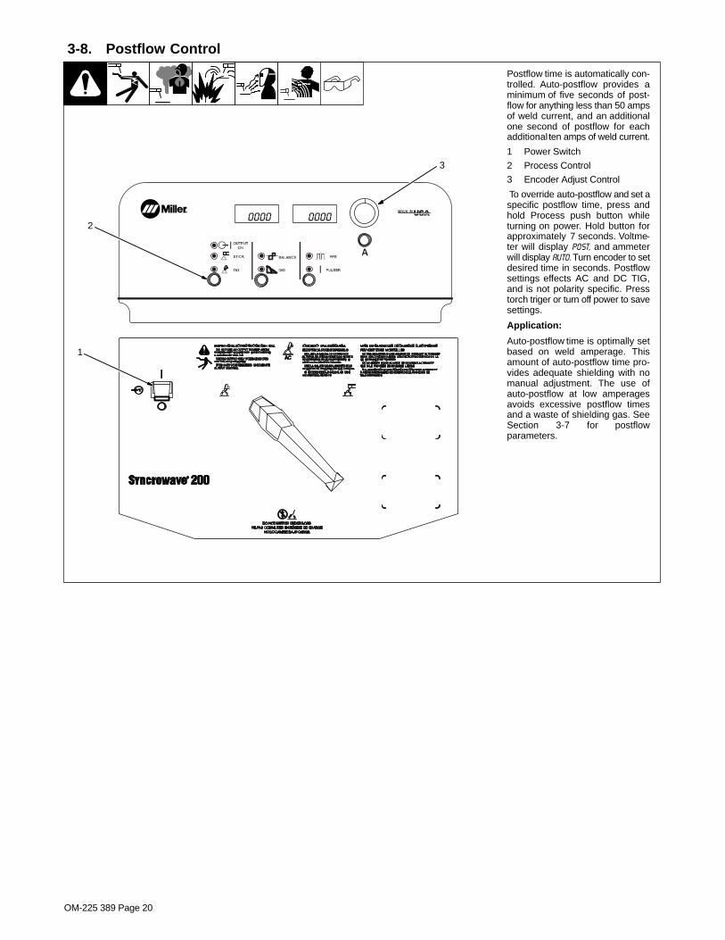
3-8. Postflow Control
1
Postflow time is automatically con-trolled. Auto-postflow provides aminimum of five seconds of post-flow for anything less than 50 ampsof weld current, and an additionalone second of postflow for eachadditional ten amps of weld current.
1 Power Switch
2 Process Control
3 Encoder Adjust Control
To override auto-postflow and set aspecific postflow time, press andhold Process push button whileturning on power. Hold button forapproximately 7 seconds. Voltme-ter will display POST, and ammeterwill display AUTO. Turn encoder to setdesired time in seconds. Postflowsettings effects AC and DC TIG,and is not polarity specific. Presstorch triger or turn off power to savesettings.
Application:
Auto-postflow time is optimally setbased on weld amperage. Thisamount of auto-postflow time pro-vides adequate shielding with nomanual adjustment. The use ofauto-postflow at low amperagesavoids excessive postflow timesand a waste of shielding gas. SeeSection 3-7 for postflowparameters.
2
3

EN
GL
ISH
OM-225 389 Page 21
0000 0000
3-9. Selecting Syncro Start Characteristics
1 Power Switch
2 Main Amps Control
3 Volt And Ammeters
4 Process Selector Switch
To change TIG HF Syncro starting char-acteristics, turn Off power, place OutputSelector switch in desired position,DCEN, DCEP or AC. Each position hasthree start characteristics options. Pushand hold Main Amps button and turn onpower. Hold button for approximately 7seconds.
Meters will display [AC] [MED] or [DCEN] [MED],or [DCEP] [MED], depending on position ofOutput Selector switch
Turn Encoder to step through the threestart characteristics choices. Ammeterdisplays active choice: soft start, me-dium start, or hot start.
Change polarity (see Section 3-1) to setvalues for each TIG output. Each settingis polarity specific.
Press torch triger or turn off power tosave settings.
Application:
Soft start - use for thin gauge materialand small diameter tungstens(.040−1/16 in)
Medium start - factory default, used formost welding applications with 1/16, 3/32and 1/8 in tungstens.
Hot start - use for thick materials with alarge diameter tungsten (1/8−5/32 in).
2
1
3
4

OM-225 389 Page 22
0000 0000
1 Power Switch
2 Pulse Control
Push and hold Pulser button and turnon power. Hold button for approxi-mately 7 seconds.
3 Encoder Control4 Volt And Ammeter
Press Pulse button to cycle parame-ters (see Section 3-7 for parameterranges).
PPS (Pulses Per Second or PulseFrequency) is used to determine ap-pearance of weld bead (See Section3-5).
PEAK t [PKT] [50%]- The percentageof each pulse cycle that can be spentat the peak amperage level.
BKGND A [BKA] [50%] - (BackgroundAmps) - Use Background Amps toset the low pulse of the weld amper-age, which cools the weld puddle andaffects overall heat input. Back-ground Amps is set as a percentageof peak amperage.
Turn encoder to select appropriatevalue for active pulse parameter. Val-ue selected is shown on the amme-ter.
5 Pulsed Output Waveforms
Example shows affect changing thePeak Time control has on the pulsedoutput waveform.
NOTE: Peak amperage is set usingthe Main Amps push button control(see Section 3-3), or with a remotecontrol. Peak amperage is the high-est welding amperage allowed to oc-cur in the pulse cycle. Weld penetra-tion varies directly with peakamperage.
Application:
Pulsed TIG welding involves switch-ing the weld output between a high orpeak amperage, and a low or back-ground amperage at a controlled rate(see Section 3-5). The raised por-tions of the weld output are controlledin width, height, and frequency, form-ing pulses of weld output. Thesepulses and the lower amperage levelbetween them (called the back-ground amperage) alternately heatand cool the molten weld puddle. Thecombined effect gives the operatorbetter control of penetration, beadwidth, crowning, undercutting, andheat input. Controls can be adjustedwhile welding.
Pulsing can also be used for filler ma-terial addition technique training.
3-10. Pulser Peak And Background
1
Peak AmpBkg Amp
Balanced
More TimeAt Peak
Amperage
More TimeAt
BackgroundAmperage
Pulsed Output WaveformsPercent (%) Peak
Time Control Setting
(50%)
(80%)
(20%)
PPS
5
2
4
3

EN
GL
ISH
OM-225 389 Page 23
3-11. Timer/Cycle Counter
3
2
1
1 Power Switch
2 Process Control
3 Pulse Control
To read timer/cycle counter, press and hold
the Process and Pulse buttons, and turnpower on.
4 Timer Display
The hours are displayed for five seconds,
and then the minutes are displayed for fiveseconds.5 Cycle DisplayThe cycles are displayed for the next fiveseconds, and are read as 12,345,678cycles.
1234 Hour
59 MINS
4
1234 5678
5
0000 0000

OM-225 389 Page 24
3-12. Software Number/Revision
3
2
1
1 Power Switch
2 Process Control
3 Adjust Control
To read software number/revision, press
and hold the Process and Adjust buttons,and turn power on.
4 Software Number Display
The software number is displayed for five
seconds.
5 Revision Display
The revision is displayed for the next fiveseconds.
221 161
4
REV.A
5
0000 0000

EN
GL
ISH
OM-225 389 Page 25
SECTION 4 − MAINTENANCE AND TROUBLESHOOTING
4-1. Routine Maintenance
! Disconnect power before maintaining.
� Maintain more often during severe conditions.
3 Months
Replace unreadable labels. Replace o-ring in Electrode/GasOutput receptacle if cracked.
Repair or replace cracked weldcable.
Repair or replace cracked gashose.
6 Months
Blow out or vacuum inside.Or
4-2. Adjusting Spark Gaps
! Disconnect and lockout/tagout in-put power before adjusting sparkgaps.
Remove right side panel.1 Tungsten End Of PointReplace point if tungsten end disappears;do not clean or dress tungsten.
2 Spark Gap
Normal spark gap is 0.008 in (0.203 mm).
If adjustment is needed, proceed as fol-lows:
3 Adjustment Screws
Loosen screws. Place gauge of properthickness in spark gap.
4 Pressure Point
Apply slight pressure at point until gauge isheld firmly in gap. Tighten screws to 12 in/lbs torque. Adjust other gap.Reinstall right side panel.
Tools Needed:
1
4
3
4
3
2
804 236-B

OM-225 389 Page 26
4-3. Voltmeter/Ammeter Help Displays
� All directions are in reference to thefront of the unit. All circuitry referred tois located inside the unit.
1 Help 0 Display
Indicates a short in the thermal protectioncircuitry located on the transformer of theunit. If this display is shown, contact a Fac-tory Authorized Service Agent.
2 Help1 Display
An SCR overcurrent condition has oc-curred. Turn power off and back on to cor-rect condition. If problem continues, con-tact a Factory Authorized Service Agent.
3 Help2 Display
Indicates an open in the thermal protectioncircuitry located on the transformer of theunit. If this display is shown, contact a Fac-
tory Authorized Service Agent.
4 OVER TEMP XFMR
Indicates the transformer of the unit hasoverheated. The unit has shut down to al-low the fan to cool it (see Section 2-6). Op-eration will continue when the unit hascooled.
5 Help 4 Display
Indicates an open in the thermal protectioncircuitry located on the rectifier assembly ofthe unit. If this display is shown, contact aFactory Authorized Service Agent.
6 OVER TEMP RECT
Indicates the rectifier assembly of the unithas overheated. The unit has shut down toallow the fan to cool it (see Section 2-6). Op-
eration will continue when the unit hascooled.7 Help 9 Display
Indicates a short in the thermal protectioncircuitry located on the rectifier assembly ofthe unit. If this display is shown, contact aFactory Authorized Service Agent.8 REL RMT
Indicates Remote Output control is acti-vated. Release Remote Output control toclear help message.
9 POL ERR
Indicates Output Selector switch is not incorrect position (see Section 3-1).10 NOT VALID
Indicates a non-allowable set-up on thefront panel.
A
A
V
V
A
A
0
2
HELP
OVER
1
TEMP
V
V
HELP
HELP
A
A
4
9
V
V
OVER
REL
A
A
TEMP
RMT
7 8
2
5 6
V
NOT
10
A
VALID
V
V
HELP
HELP
1
V
POL
9
A
ERR
3 4
XFMR
RECT
Toggles EveryTwo Seconds}
Toggles EveryTwo Seconds}

EN
GL
ISH
OM-225 389 Page 27
4-4. Troubleshooting
NOTE: The remedies listed below are recommendations only. If these remedies do not fixthe trouble with your unit, have a Factory Authorized Service Agent check unit.There are no user serviceable parts inside unit.
Refer to Section 4-3 for any Help (HLP) message displayed on voltmeter/ammeter.
Trouble Remedy
No weld output; unit completelyinoperative.
Place machine power switch in On position (see Section 3-1).
Place line disconnect switch in On position (see Section 2-16).
Check and replace line fuse(s), if necessary (see Section 2-16).
Check for proper input power connections (see Section 2-16).
No weld output; unit on. Check, repair, or replace remote control.
Have Factory Authorized Service Agent check unit.
Unit provides only maximum orminimum weld output.
Make sure Amperage control is in proper position (see Section 3-1).
Have Factory Authorized Service Agent check unit.
Erratic or improper weld output. Use proper size and type of weld cable (see Section 2-9).
Clean and tighten all weld connections.
Lay weld cables out straight, do not leave weld cables coiled.
Check position of Output Selector control (see Section Figure 3-1).
If using remote control, check position of Amperage Adjustment control (see Section 3-1).
No control of weld output. Make sure Amperage control is in proper position (see Section 3-1).
Lack of high frequency; difficulty instarting GTAW arc.
Select proper size tungsten (see Section 7-1).
Be sure torch cable is not close to any grounded metal.
Check cables and torch for cracked insulation or bad connections. Repair or replace.
Check spark gaps (see Section 4-2).
Wandering arc − poor control ofdirection of arc.
Reduce gas flow rate (see Section 2-13).
Select proper size tungsten (see Section 7-1).
Properly prepare tungsten (see Section 7-2).
Tungsten electrode oxidizing and notremaining bright after conclusion ofweld.
Shield weld zone from drafts.
Increase postflow time (see Section 3-8).
Check and tighten all gas fittings.
Properly prepare tungsten (see Section 7-2).
Fan not operating. Unit equipped with Fan-On-Demand�. Fans run only when necessary. Unit equipped with circuitry toprotect against overheating.
No weld output; fan does not run. Place line disconnect switch in On position (see Section 2-16).
Check and replace line fuse(s), if necessary, or reset circuit breaker (see Section 2-16).
Check for proper input power connections (see Section 2-16).
No weld output; fan on. Be sure Output Selector switch is not set between positions (see Section 3-1).
Tighten remote control connection to Remote 14 receptacle (see Section 2-10).
Check remote control (see remote control Owner’s Manual).
Unit overheated. Allow unit to cool (see Section 2-6).
Fan not operating; weld outputavailable.
Check for and remove anything blocking fan movement.
Have Factory Authorized Service Agent check fan motor.

OM-225 389 Page 28
SECTION 5 − ELECTRICAL DIAGRAM
231 276-B
Figure 5-1. Circuit Diagram For 208−230 Volt Models

EN
GL
ISH
OM-225 389 Page 29
231 299-B
Figure 5-2. Circuit Diagram For 460/575 Volt Models

OM-225 389 Page 30
SECTION 6 − HIGH FREQUENCY
6-1. Welding Processes Requiring High Frequency
high_freq 7/05 − S-0693
1 High-Frequency Voltage
TIG − helps arc jump air gapbetween torch and workpiece and/or stabilize the arc.1
TIG
Work
6-2. Incorrect Installation
50 ft(15 m)
S-0694
Sources of Direct High-FrequencyRadiation1 High-Frequency Source (welding
power source with built-in HF orseparate HF unit)
2 Weld Cables3 Torch4 Work Clamp5 Workpiece6 Work Table
Sources of Conduction of HighFrequency7 Input Power Cable8 Line Disconnect Device9 Input Supply Wiring
Sources of Reradiation of HighFrequency10 Ungrounded Metal Objects11 Lighting12 Wiring13 Water Pipes and Fixtures14 External Phone and Power Lines
Weld Zone
13
9
8
7
1
2
4 5 6
3
10
11, 12
14

EN
GL
ISH
OM-225 389 Page 31
6-3. Correct Installation
1 High-Frequency Source (weldingpower source with built-in HF orseparate HF unit)
Ground metal machine case, work outputterminal, line disconnect device, inputsupply, and worktable.2 Center Point of Welding ZoneMidpoint between high-frequency sourceand welding torch.3 Welding ZoneA circle 50 ft (15 m) from center point in alldirections.4 Weld Output CablesKeep cables short and close together.
5 Conduit Joint Bonding and Grounding
Electrically join (bond) all conduit sectionsusing copper straps or braided wire.Ground conduit every 50 ft (15 m).
6 Water Pipes and Fixtures
Ground water pipes every 50 ft (15 m).
7 External Power or Telephone Lines
Locate high-frequency source at least 50 ft(15 m) away from power and phone lines.
8 Grounding Rod
Consult the National Electrical Code forspecifications.
Metal Building Requirements
9 Metal Building Panel BondingMethods
Bolt or weld building panels together, installcopper straps or braided wire acrossseams, and ground frame.
10 Windows and Doorways
Cover all windows and doorways withgrounded copper screen of not more than1/4 in (6.4 mm) mesh.
11 Overhead Door Track
Ground the track.
Ref. S-0695 / Ref. S-0695
1
2
3 50 ft(15 m)
Weld Zone
4
7
50 ft(15 m)
8
5
8
6
Groundworkpieceif requiredby codes.
Ground all metal ob-jects and all wiring inwelding zone using#12 AWG wire.
NonmetalBuilding
9
11
10
Metal Building
88

OM-225 389 Page 32
SECTION 7 − SELECTING AND PREPARING A TUNGSTENFOR DC OR AC WELDING
gtaw_Phase_2007−04
! Whenever possible and practical, use DC weld output instead of AC weld output.
7-1. Selecting Tungsten Electrode (Wear Clean gloves To Prevent Contamination Of Tungsten)
Amperage Range - Gas Type♦ - Polarity
Electrode Diameter (DCEN) − Argon
Direct Current Electrode Negative
(For Use With Mild Or Stainless Steel)
AC − Argon
Balance Control @ 65% Electrode Negative(For Use With Aluminum)
2% Ceria (Orange Band), 1.5% Lanthanum (Gray Band), Or 2% Thorium (Red Band) Alloy Tungstens
.040” (1 mm) 25-85 20-80
1/16” (1.6 mm) 50-160 50-150
3/32” (2.4 mm) 135-235 130-250
1/8” (3.2 mm) 250-400 225-360
Pure Tungsten (Green Band)
.040” (1 mm) Pure Tungsten Not Recommended
For DCEN − Argon
10-60
1/16” (1.6 mm) 50-100
3/32” (2.4 mm) 100-160
1/8” (3.2 mm) 150-210
♦Typical argon shielding gas flow rates are 11 to 35 cfh (cubic feet per hour).
Figures listed are a guide and are a composite of recommendations from American Welding Society (AWS) and electrode manufacturers.
7-2. Preparing Tungsten Electrode For Welding With Phase Control Machines
! Grinding the tungsten electrode produces dust and flying sparks which can cause injury and start fires. Uselocal exhaust (forced ventilation) at the grinder or wear an approved respirator. Read MSDS for safety infor-mation. Consider using tungsten containing ceria, lanthana, or yttria instead of thoria. Grinding dust fromthoriated electrodes contains low-level radioactive material. Properly dispose of grinder dust in an environ-mentally safe way. Wear proper face, hand, and body protection. Keep flammables away.
A. Preparing Tungsten For DC Electrode Negative (DCEN) Welding
Ideal Tungsten Preparation − Stable Arc
2-1/2 TimesElectrode Diameter
1 Grinding Wheel
Grind end of tungsten on fine grit, hardabrasive wheel before welding. Do not usewheel for other jobs or tungsten can becomecontaminated causing lower weld quality.
2 Tungsten Electrode
A 2% ceriated tungsten is recommended.
3 Flat
Diameter of this flat determines amperagecapacity.
4 Straight Ground
Grind lengthwise, not radial.
1
3
4
1 Tungsten Electrode
A pure tungsten is recommended..
2 Balled End
Ball end of tungsten by applying AC amper-age recommended for a given electrodediameter (see Section 7-1). Let ball on end ofthe tungsten take its own shape.
B. Preparing Tungsten For AC Welding
1 − 1-1/2 Times
2
Electrode Diameter
Causes Wandering Arc2
1
Wrong Tungsten Preparation
Radial Grinding

EN
GL
ISH
OM-225 389 Page 33
SECTION 8 − GUIDELINES FOR TIG WELDING (GTAW)2007−04
8-1. Positioning The Torch
Ref. ST-161 892
! Grinding the tungsten elec-trode produces dust and fly-ing sparks which can causeinjury and start fires. Use lo-cal exhaust (forced ventila-tion) at the grinder or wear anapproved respirator. ReadMSDS for safety information.Consider using cerium orlanthanum based tungsteninstead of thoriated. Tho-rium dust contains low-levelradioactive material. Proper-ly dispose of grinder dust inan environmentally safe way.Wear proper face, hand, andbody protection. Keep flam-mables away.
1 Workpiece
Make sure workpiece is cleanbefore welding.
2 Work Clamp
Place as close to the weld aspossible.
3 Torch
4 Filler Rod (If Applicable)
5 Gas Cup
6 Tungsten Electrode
Select and prepare tungstenaccording to Section 7.
Guidelines:
The inside diameter of the gas cupshould be at least three times thetungsten diameter to provide ade-quate shielding gas coverage. (Forexample, if tungsten is 1/16 indiameter, gas cup should be aminimum of 3/16 in diameter.
Tungsten extension is the distancethe tungsten extends out gas cup oftorch.
The tungsten extension should beno greater than the inside diameterof the gas cup.
Arc length is the distance from thetungsten to the workpiece.
1
10−25°
10−15°
6
2
3
4
90°
4
5
3/16 in
1/16 in
65
Bottom View Of Gas Cup

OM-225 389 Page 34
8-2. Torch Movement During Welding
ST-162 002-B
Tungsten Without Filler Rod
Tungsten With Filler Rod
Form pool Tilt torch Move torch to frontof pool. Repeat process.
75°
75°Welding direction
Form pool Tilt torch Add filler metal
Move torch to frontof pool. Repeat process.
Remove rod
Welding direction 15°

EN
GL
ISH
OM-225 389 Page 35
8-3. Positioning Torch Tungsten For Various Weld Joints
ST-162 003 / S-0792
70°
70°
90°
20°
20°
10°20°
70°
40°
30°
20°
70°
90°
20°
Butt Weld And Stringer Bead
“T” Joint
Lap Joint
Corner Joint

OM-225 389 Page 36
SECTION 9 − STICK WELDING (SMAW) GUIDELINES
9-1. Stick Welding Procedure
stick 2008−05 − ST-151 593
! Weld current starts whenelectrode touches work-piece.
! Weld current can damageelectronic parts in vehicles.Disconnect both batterycables before welding on avehicle. Place work clampas close to the weld aspossible.
� Always wear appropriate per-sonal protective clothing.
1 Workpiece
Make sure workpiece is clean be-fore welding.
2 Work Clamp
3 Electrode
A small diameter electrode re-quires less current than a largeone. Follow electrode manufactur-er’s instructions when setting weldamperage (see Section 9-2).
4 Insulated Electrode Holder
5 Electrode Holder Position
6 Arc Length
Arc length is the distance from theelectrode to the workpiece. A shortarc with correct amperage will givea sharp, crackling sound.
7 Slag
Use a chipping hammer and wirebrush to remove slag. Removeslag and check weld bead beforemaking another weld pass.
1
4
3
5
2
7
6
Tools Needed: Equipment Needed:
Constant CurrentWelding Power Source

OM-225 389 Page 37
9-2. Electrode and Amperage Selection Chart
Ref. S-087 985-A
3/321/8
5/323/167/321/4
1/165/643/321/8
5/323/167/321/4
3/321/8
5/323/167/321/4
3/321/8
5/323/167/321/4
3/321/8
5/323/167/321/4
3/321/8
5/323/163/321/8
5/32
6010&
6011
6013
7014
7018
7024
Ni-Cl
308L
50 100
150
200
250
300
350
400
450 ELE
CT
RO
DE
DC
*
AC
PO
SIT
ION
PE
NE
TR
AT
ION
US
AG
E
MIN. PREP, ROUGHHIGH SPATTER
GENERAL
SMOOTH, EASY,FAST
LOW HYDROGEN,STRONG
SMOOTH, EASY,FASTER
CAST IRON
STAINLESS
DEEP
DEEP
LOW
MED
LOW
LOW
LOW
LOW
ALL
ALL
ALL
ALL
ALL
FLATHORIZFILLET
ALL
ALL
EP
EP
EP,EN
EP,EN
EP
EP,EN
EP
EP
6010
6011
6013
7014
7018
7024
NI-CL
308L
*EP = ELECTRODE POSITIVE (REVERSE POLARITY) EN = ELECTRODE NEGATIVE (STRAIGHT POLARITY)
ELE
CT
RO
DE
AM
PE
RA
GE
RA
NG
E
DIA
ME
TE
R
9-3. Striking an Arc
S-0049 / S-0050
1 Electrode
2 Workpiece
3 Arc
Scratch Technique
Drag electrode across workpiecelike striking a match; lift electrodeslightly after touching work. If arcgoes out, electrode was lifted toohigh. If electrode sticks to work-piece, use a quick twist to free it.
Tapping Technique
Bring electrode straight down toworkpiece; then lift slightly to startarc. If arc goes out, electrode waslifted too high. If electrode sticks toworkpiece, use a quick twist to freeit.
1
2
3
1
3
2

OM-225 389 Page 38
9-4. Positioning Electrode Holder
S-0060
90° 90°
10°-30°
45°
45° 10°-30°
1 End View Of Work Angle
2 Side View Of Electrode Angle
1
1
2
2
Groove Welds
Fillet Welds
9-5. Poor Weld Bead Characteristics
S-0053-A
1 Large Spatter Deposits
2 Rough, Uneven Bead
3 Slight Crater During Welding
4 Bad Overlap
5 Poor Penetration
5
4
2 3
1
9-6. Good Weld Bead Characteristics
S-0052-B
1 Fine Spatter
2 Uniform Bead
3 Moderate Crater DuringWelding
Weld a new bead or layer for each1/8 in. (3.2 mm) thickness in met-als being welded.
4 No Overlap
5 Good Penetration into BaseMetal
1
52 3 4

OM-225 389 Page 39
9-7. Conditions That Affect Weld Bead Shape
S-0061
Slow Normal Fast
10° - 30°
Drag
Too Short Normal Too Long
Spatter
Angle Too Small Angle Too LargeCorrect Angle
Electrode Angle
Arc Length
Travel Speed
� Weld bead shape is affectedby electrode angle, arclength, travel speed, and thick-ness of base metal.
9-8. Electrode Movement During Welding
S-0054-A
� Normally, a single stringerbead is satisfactory for mostnarrow groove weld joints;however, for wide groove weldjoints or bridging across gaps,a weave bead or multiplestringer beads work better.
1 Stringer Bead − SteadyMovement Along Seam
2 Weave Bead − Side to SideMovement Along Seam
3 Weave Patterns
Use weave patterns to cover awide area in one pass of the elec-trode. Do not let weave width ex-ceed 2-1/2 times diameter ofelectrode.
1 2
3

OM-225 389 Page 40
9-9. Butt Joints
S-0062
1 Tack Welds
Prevent edges of joint from draw-ing together ahead of electrode bytack welding the materials in posi-tion before final weld.
2 Square Groove Weld
Good for materials up to 3/16 in. (5mm) thick.
3 Single V-Groove Weld
Good for materials 3/16 − 3/4 in.(5-19 mm) thick. Cut bevel withoxyacetylene or plasma cuttingequipment. Remove scale frommaterial after cutting. A grinder canalso be used to prepare bevels.
Create 30 degree angle of bevel onmaterials in V-groove welding.
4 Double V-Groove Weld
Good for materials thicker than3/16 in. (5 mm).
30°
2
1
1/16 in.(1.6 mm)
3 4
9-10. Lap Joint
S-0063 / S-0064
1 Electrode
2 Single-Layer Fillet Weld
Move electrode in circular motion.
3 Multi-Layer Fillet Weld
Weld a second layer when a heavi-er fillet is needed. Remove slag be-fore making another weld pass.Weld both sides of joint for maxi-mum strength.
30°Or Less
30°Or Less
1 1
2 3
9-11. Tee Joint
S-0060 / S-0058-A / S-0061
1 Electrode
2 Fillet Weld
Keep arc short and move at defi-nite rate of speed. Hold electrodeas shown to provide fusion into thecorner. Square edge of the weldsurface.
For maximum strength weld bothsides of upright section.
3 Multi-Layer Deposits
Weld a second layer when a heavi-er fillet is needed. Use any of theweaving patterns shown in Section9-8. Remove slag before makinganother weld pass.
45°Or
Less
1
2
1
32

OM-225 389 Page 41
9-12. Weld Test
S-0057-B
1 Vise
2 Weld Joint
3 Hammer
Strike weld joint in direction shown.A good weld bends over but doesnot break.
2 To 3 in.
1/4 in.
3
2
1
2 To 3 in.
3
2
1
(51-76 mm)
(6.4 mm)
(51-76 mm)
9-13. Troubleshooting
Porosity − small cavities or holes resulting from gas pockets in weld metal.
Possible Causes Corrective Actions
Arc length too long. Reduce arc length.
Damp electrode. Use dry electrode.
Workpiece dirty. Remove all grease, oil, moisture, rust, paint, coatings, slag, and dirt from work surface beforewelding.
Excessive Spatter − scattering of molten metal particles that cool to solid form near weld bead.
Possible Causes Corrective Actions
Amperage too high for electrode. Decrease amperage or select larger electrode.
Arc length too long or voltage too high. Reduce arc length or voltage.
Incomplete Fusion − failure of weld metal to fuse completely with base metal or a preceedingweld bead.
Possible Causes Corrective Actions
Insufficient heat input. Increase amperage. Select larger electrode and increase amperage.
Improper welding technique. Place stringer bead in proper location(s) at joint during welding.
Adjust work angle or widen groove to access bottom during welding.
Momentarily hold arc on groove side walls when using weaving technique.
Keep arc on leading edge of weld puddle.
Workpiece dirty. Remove all grease, oil, moisture, rust, paint, coatings, slag, and dirt from work surface beforewelding.

OM-225 389 Page 42
Lack of Penetration Good Penetration
Lack Of Penetration − shallow fusion between weld metal and base metal.
Possible Causes Corrective Actions
Improper joint preparation. Material too thick. Joint preparation and design must provide access to bottom of groove.
Improper weld technique. Keep arc on leading edge of weld puddle.
Insufficient heat input. Increase amperage. Select larger electrode and increase amperage.
Reduce travel speed.
Good PenetrationExcessive Penetration
Excessive Penetration − weld metal melting through base metal and hanging underneath weld.
Possible Causes Corrective Actions
Excessive heat input. Select lower amperage. Use smaller electrode.
Increase and/or maintain steady travel speed.
Burn-Through − weld metal melting completely through base metal resulting in holes where nometal remains.
Possible Causes Corrective Actions
Excessive heat input. Select lower amperage. Use smaller electrode.
Increase and/or maintain steady travel speed.
Waviness Of Bead − weld metal that is not parallel and does not cover joint formed by base metal.
Possible Causes Corrective Actions
Unsteady hand. Use two hands. Practice technique.
Base metal movesin the direction of
the weld bead.
Distortion − contraction of weld metal during welding that forces base metal to move.
Possible Causes Corrective Actions
Excessive heat input. Use restraint (clamp) to hold base metal in position.
Make tack welds along joint before starting welding operation.
Select lower amperage for electrode.
Increase travel speed.
Weld in small segments and allow cooling between welds.

OM-225 389 Page 43
Notes
Work like a Pro!
Pros weld and cut
safely. Read the
safety rules at
the beginning
of this manual.

OM-225 389 Page 44
SECTION 10 − PARTS LIST
804 237-G
� Hardware is common andnot available unless listed.
1
2
5756
5553
4
3
5
6
7 89
10
14
1312
11
15
1718
57
2122
23
20
27
26
28
29
3031
32
33
34
572535
3738
25
36
1624
3940
41
4243
47
46
45 44
4849
51 5052
58
59
60
6162
Figure 10-1. Main Assembly

OM-225 389 Page 45
DescriptionPartNo.
Dia.Mkgs.
ItemNo.
Figure 10-1. Main Assembly
Quantity
1 223 302 HANDLE 2. . . . . . . . . . . . . . . . . . . . . . . . . . . . . . . . . . . . . . . . . . . . . . . . . . . . . . . . . . . . . . . . . . . . . . . . . . 2 222 779 FRONT, BEZEL 1. . . . . . . . . . . . . . . . . . . . . . . . . . . . . . . . . . . . . . . . . . . . . . . . . . . . . . . . . . . . . . . . . . . 3 169 136 PIN, HANDLE 1. . . . . . . . . . . . . . . . . . . . . . . . . . . . . . . . . . . . . . . . . . . . . . . . . . . . . . . . . . . . . . . . . . . . . 4 175 952 PLASTIC, HANDLE SWITCH 1. . . . . . . . . . . . . . . . . . . . . . . . . . . . . . . . . . . . . . . . . . . . . . . . . . . . . . . . 5 195 778 ACTUATOR PUSH BUTTON ASSY 4. . . . . . . . . . . . . . . . . . . . . . . . . . . . . . . . . . . . . . . . . . . . . . . . . . 6 222 782 NAMEPLATE, SYNCROWAVE 200 UPPER 1. . . . . . . . . . . . . . . . . . . . . . . . . . . . . . . . . . . . . . . . . . 7 222 776 PANEL, FRONT 1. . . . . . . . . . . . . . . . . . . . . . . . . . . . . . . . . . . . . . . . . . . . . . . . . . . . . . . . . . . . . . . . . . 8 183 332 KNOB, POINTER .570 DIA X .125 ID W/SPRING CLIP 1. . . . . . . . . . . . . . . . . . . . . . . . . . . . . . . . . 9 224 498 BUSHING, FLG 375−32X423 1. . . . . . . . . . . . . . . . . . . . . . . . . . . . . . . . . . . . . . . . . . . . . . . . . . . . . . . .
10 190 512 STAND−OFF,NO 6−32 X .640 LG .250 HEX AL FEM 5. . . . . . . . . . . . . . . . . . . . . . . . . . . . . . . . . . . 11 S5 222 793 SWITCH ASSY, POLARITY W/LEADS & HARDWARE 1. . . . . . . . . . . . . . . . . . . . . . . . . . . . 12 S1 128755 SWITCH, TGL DPST 40A 600VAC SCR TERM WIDE TGL 1. . . . . . . . . . . . . . . . . . . . . . . . . 13 C5,C6 223 952 CAPACITOR ASSY 1. . . . . . . . . . . . . . . . . . . . . . . . . . . . . . . . . . . . . . . . . . . . . . . . . . . . . . . . . 14 PC1 231 996 CIRCUIT CARD ASSY, CONTROL & INTERFACE W/PROGRAM 1. . . . . . . . . . . . . . . . . . 15 T1/Z1 223 299 XFMR/STABILIZER ASSY (208−230 VOLT MODELS) 1. . . . . . . . . . . . . . . . . . . . . . . . . . . 15 T1/Z1 226 884 XFMR/STABILIZER ASSY (460/575 VOLT MODELS) 1. . . . . . . . . . . . . . . . . . . . . . . . . . . 16 224 442 LIFT EYE 1. . . . . . . . . . . . . . . . . . . . . . . . . . . . . . . . . . . . . . . . . . . . . . . . . . . . . . . . . . . . . . . . . . . . . . . . . 17 199 479 LABEL, MILLER 9.562 X 4.000 HORIZONTAL 2. . . . . . . . . . . . . . . . . . . . . . . . . . . . . . . . . . . . . . . . . 18 222 774 PANEL, SIDE 2. . . . . . . . . . . . . . . . . . . . . . . . . . . . . . . . . . . . . . . . . . . . . . . . . . . . . . . . . . . . . . . . . . . . . 20 203 990 LABEL, WARNING GENERAL PRECAUTIONARY STATIC 1. . . . . . . . . . . . . . . . . . . . . . . . . . . . . 21 223 303 HANGER,CABLE/TORCH (PART OF ACCESSORY KIT) 1. . . . . . . . . . . . . . . . . . . . . . . . . . . . . . . 22 +225 673 COVER, TOP 1. . . . . . . . . . . . . . . . . . . . . . . . . . . . . . . . . . . . . . . . . . . . . . . . . . . . . . . . . . . . . . . . . . . . 23 213 073 SEAL, LIFT EYE 1. . . . . . . . . . . . . . . . . . . . . . . . . . . . . . . . . . . . . . . . . . . . . . . . . . . . . . . . . . . . . . . . . . . 24 224 441 PLENUM, MID PLANE 1. . . . . . . . . . . . . . . . . . . . . . . . . . . . . . . . . . . . . . . . . . . . . . . . . . . . . . . . . . . . . 25 R1,R4 220 808 RESISTOR, WW FXD 100 W 50 OHM W/CLIPS 2. . . . . . . . . . . . . . . . . . . . . . . . . . . . . . . . 26 213 072 FAN, MUFFIN 1. . . . . . . . . . . . . . . . . . . . . . . . . . . . . . . . . . . . . . . . . . . . . . . . . . . . . . . . . . . . . . . . . . . . . 27 223 300 HOLDER, FOOT PEDAL (PART OF ACCESSORY KIT) 1. . . . . . . . . . . . . . . . . . . . . . . . . . . . . . . . 28 222 778 BAFFLE, FAN 1. . . . . . . . . . . . . . . . . . . . . . . . . . . . . . . . . . . . . . . . . . . . . . . . . . . . . . . . . . . . . . . . . . . . . 29 GS 238 805 VALVE, 24VDC 2WAY,125 PSI CUSTOM PORT.054 ORF W/FRICTION 1. . . . . . . . . . . . . 30 +222 777 PANEL, REAR 1. . . . . . . . . . . . . . . . . . . . . . . . . . . . . . . . . . . . . . . . . . . . . . . . . . . . . . . . . . . . . . . . . . . . 31 604 102 CONN, CLAMP CABLE 1.000 1. . . . . . . . . . . . . . . . . . . . . . . . . . . . . . . . . . . . . . . . . . . . . . . . . . . . . . . 32 240 997 CORD SET, 250V 8GA 3/C 8’ ST JKT (208−230 VOLT MODELS ONLY) 1. . . . . . . . . . . . . . . . . . 33 137 761 NUT, 750 NPT 1.31HEX .27H NYL BLK 1. . . . . . . . . . . . . . . . . . . . . . . . . . . . . . . . . . . . . . . . . . . . . . . 34 185 759 LABEL, WARNING ELECTRIC SHOCK & INPUT POWER 1. . . . . . . . . . . . . . . . . . . . . . . . . . . . . . 35 SR2 035 704 RECTIFIER, INTEG BRIDGE 40. AMP 800V 1. . . . . . . . . . . . . . . . . . . . . . . . . . . . . . . . . . . . . 36 CR1 173 069 RELAY,ENCL 12VDC SPDT 30A/20A 5PIN FLANGE MTG 1. . . . . . . . . . . . . . . . . . . . . . . . 37 R2 189 132 RESISTOR ASSY 1. . . . . . . . . . . . . . . . . . . . . . . . . . . . . . . . . . . . . . . . . . . . . . . . . . . . . . . . . . . . . 38 C1 191 944 CAPACITOR, POLYP MET FILM 10. UF 250 VAC 10% 1. . . . . . . . . . . . . . . . . . . . . . . . . . . . . 39 HD1 191 941 TRANSDUCER, CURRENT 1. . . . . . . . . . . . . . . . . . . . . . . . . . . . . . . . . . . . . . . . . . . . . . . . . . . . 40 224 496 RECTIFIER ASSY, (FIGURE 10-3) 1. . . . . . . . . . . . . . . . . . . . . . . . . . . . . . . . . . . . . . . . . . . . . . . . . . . 41 +222 781 PANEL, WINDTUNNEL 1. . . . . . . . . . . . . . . . . . . . . . . . . . . . . . . . . . . . . . . . . . . . . . . . . . . . . . . . . . . . 42 224 460 LABEL, WARNING ELECTRICAL SHOCK SPARK GAP(ENG/FR) 1. . . . . . . . . . . . . . . . . . . . . . . 43 C18 195 552 CAPACITOR, POLYP MET FILM 20. UF 250 VAC 10% 1. . . . . . . . . . . . . . . . . . . . . . . . . . . . 44 C3 215 779 CAPACITOR, MICA .002 UF 10000 V PANEL MTG W/LEA 1. . . . . . . . . . . . . . . . . . . . . . . . . . 45 T3 219 927 XFMR, HIGH VOLTAGE 115V PRI 3600V SEC 34 MA W/TERM 1. . . . . . . . . . . . . . . . . . . . . 46 G1 221 738 SPARK GAP ASSY, HF (INCLUDES) 1. . . . . . . . . . . . . . . . . . . . . . . . . . . . . . . . . . . . . . . . . . . . .
221735 BASE, SPARK GAP 1. . . . . . . . . . . . . . . . . . . . . . . . . . . . . . . . . . . . . . . . . . . . . . . . . . . . . . . . . . . . . . . . . . 221734 HOLDER, POINTS 3. . . . . . . . . . . . . . . . . . . . . . . . . . . . . . . . . . . . . . . . . . . . . . . . . . . . . . . . . . . . . . . . . . . 221736 POINTS, SPARK GAP (DUAL) 1. . . . . . . . . . . . . . . . . . . . . . . . . . . . . . . . . . . . . . . . . . . . . . . . . . . . . . . . . 221737 POINTS, SPARK GAP (SINGLE) 2. . . . . . . . . . . . . . . . . . . . . . . . . . . . . . . . . . . . . . . . . . . . . . . . . . . . . . .
47 R8 211 261 RESISTOR, WW FXD 100 W 200 OHM W/CLIPS 1. . . . . . . . . . . . . . . . . . . . . . . . . . . . . . . . . . 48 222 773 BASE 1. . . . . . . . . . . . . . . . . . . . . . . . . . . . . . . . . . . . . . . . . . . . . . . . . . . . . . . . . . . . . . . . . . . . . . . . . . . . 49 C14 206 878 CAPACITOR ASSY 1. . . . . . . . . . . . . . . . . . . . . . . . . . . . . . . . . . . . . . . . . . . . . . . . . . . . . . . . . . . 50 T4 222 793 COIL, COUPLING 1. . . . . . . . . . . . . . . . . . . . . . . . . . . . . . . . . . . . . . . . . . . . . . . . . . . . . . . . . . . . . 51 207 560 INSULATOR, STAND−OFF WITH STUD 2. . . . . . . . . . . . . . . . . . . . . . . . . . . . . . . . . . . . . . . . . . . . . . 52 228 150 NAMEPLATE, SYNCROWAVE 200 LOWER 1. . . . . . . . . . . . . . . . . . . . . . . . . . . . . . . . . . . . . . . . 53 218 170 HOSE, NPRN BRD NO 1 X .250 ID X 25.000 1. . . . . . . . . . . . . . . . . . . . . . . . . . . . . . . . . . . . . . . . . .

OM-225 389 Page 46
DescriptionPartNo.
Dia.Mkgs.
ItemNo.
Figure 10-1. Main Assembly (continued)
Quantity
55 C13 209 587 CAPACITOR ASSY 1. . . . . . . . . . . . . . . . . . . . . . . . . . . . . . . . . . . . . . . . . . . . . . . . . . . . . . . . . . . 56 223 981 PANEL, LOWER DINSE CONN ASSY (FIGURE10-2) 1. . . . . . . . . . . . . . . . . . . . . . . . . . . . . . . . . . 57 224 452 FACTORY OPTIONAL RUNNING GEAR (FIGURE 10-4) 1. . . . . . . . . . . . . . . . . . . . . . . . . . . . . . . 58 TE1 224 127 TERM ASSY, PRI 1PH 3V(460/575 VOLT MODELS) 1. . . . . . . . . . . . . . . . . . . . . . . . . . . . 59 228 010 LABEL, RATING CARD SYN 200 208−230V 1. . . . . . . . . . . . . . . . . . . . . . . . . . . . . . . . . . . . . . . . . 59 228 011 LABEL, RATING CARD SYN 200 460/575V 1. . . . . . . . . . . . . . . . . . . . . . . . . . . . . . . . . . . . . . . . 60 228 718 CORE, FERRITE BOX CLAMPON .350” BLK 1. . . . . . . . . . . . . . . . . . . . . . . . . . . . . . . . . . . . . 61 TH2 206 327 THERMISTOR, NTC 30K OHM @ 25 DEG C 27 IN LEAD 1. . . . . . . . . . . . . . . . . . . . . . . . . 62 TH1 201 443 THERMISTOR, NTC 10K OHM @ 25 DEG C 27.50IN LEAD 1. . . . . . . . . . . . . . . . . . . . . . .
141 162 HOUSING PLUG+PINS, (SERVICE KIT) 0. . . . . . . . . . . . . . . . . . . . . . . . . . . . . . . . . . . . . . . . . . . . . . . . 224 452 KIT, ACCESSORY (INCLUDES) (ALSO INCLUDES ITEMS 21 AND 27). . . . . . . . . . . . . . . . . .
(SEE FIGURE 10-1) 1. . . . . . . . . . . . . . . . . . . . . . . . . . . . . . . . . . . . . . . . . . . . . . . . . . . . . . . . . . . . . . . . . . . . . . . . . . . . 209 282 RFCS-14, FOOT CONTROL 1. . . . . . . . . . . . . . . . . . . . . . . . . . . . . . . . . . . . . . . . . . . . . . . . . . . . . . . . . . . 188 860 WORK CABLE, W/CLAMP 1. . . . . . . . . . . . . . . . . . . . . . . . . . . . . . . . . . . . . . . . . . . . . . . . . . . . . . . . . . . . . 192 121 REGULATOR/FLOWMETER 1. . . . . . . . . . . . . . . . . . . . . . . . . . . . . . . . . . . . . . . . . . . . . . . . . . . . . . . . . . . 176 840 HOLDER, ELECTRODE W/CABLE & DINSE CONNECTOR 1. . . . . . . . . . . . . . . . . . . . . . . . . . . . . . . . 198 317 HOSE, GAS 1. . . . . . . . . . . . . . . . . . . . . . . . . . . . . . . . . . . . . . . . . . . . . . . . . . . . . . . . . . . . . . . . . . . . . . . . . .
WP1712SFDI50 TORCH PKG, 150A, 12FT, AIR, W/ 50MM FLOW CONNECTOR 1. . . . . . . . . . . . . . . . . . . .
+When ordering a component originally displaying a precautionary label, the label should also be ordered.To maintain the factory original performance of your equipment, use only Manufacturer’s SuggestedReplacement Parts. Model and serial number required when ordering parts from your local distributor.

OM-225 389 Page 47
803 775-B
� Hardware is common andnot available unless listed.
1
12
6
5
4
3
2
53
4
10
9
8
7
11
9
8
7
13
Figure 10-2. Panel, Lower Dinse Connector Assembly
DescriptionPartNo.
Dia.Mkgs.
223 981
ItemNo.
10-2. Panel, Lower Dinse Connector Assy (Figure 10-1 Item 56)
Quantity
1 213 109 PANEL, LOWER DINSE CONN 1. . . . . . . . . . . . . . . . . . . . . . . . . . . . . . . . . . . . . . . . . . . . . . . . . . . . . . 2 218 174 RECEPTACLE, W/LEADS & CIRCUIT BREAKER 1. . . . . . . . . . . . . . . . . . . . . . . . . . . . . . . . . . . . . . 3 185 717 NUT, M20−1.5 1.00HEX .19H BRS LOCKING 2. . . . . . . . . . . . . . . . . . . . . . . . . . . . . . . . . . . . . . . . . 4 229 338 WASHER, DOMED LOAD .812 ID X 1.450 OD X .070 THK 2. . . . . . . . . . . . . . . . . . . . . . . . . . . . . 5 185 713 INSULATOR, BULKHEAD REAR 2. . . . . . . . . . . . . . . . . . . . . . . . . . . . . . . . . . . . . . . . . . . . . . . . . . . . 6 224 529 CONN, CIRC MS/CPC 14SKT SIZE 20 RCPT W/FILTERING 1. . . . . . . . . . . . . . . . . . . . . . . . . . . . 7 185 718 O−RING, 0.989 ID X 0.070 H 2. . . . . . . . . . . . . . . . . . . . . . . . . . . . . . . . . . . . . . . . . . . . . . . . . . . . . . . . 8 185 712 INSULATOR, BULKHEAD FRONT 2. . . . . . . . . . . . . . . . . . . . . . . . . . . . . . . . . . . . . . . . . . . . . . . . . . . 9 186 228 O−RING, 0.739 ID X 0.070 H 2. . . . . . . . . . . . . . . . . . . . . . . . . . . . . . . . . . . . . . . . . . . . . . . . . . . . . . . .
10 202 811 RECEPTACLE,TWIST LOCK ASSY 1. . . . . . . . . . . . . . . . . . . . . . . . . . . . . . . . . . . . . . . . . . . . . . . . . 11 202 553 RECEPTACLE, TWIST LOCK BRASS POWER (FEMALE) 1. . . . . . . . . . . . . . . . . . . . . . . . . . . . . . 12 218 784 LABEL, COMPONENT IDENTIFICATION 1. . . . . . . . . . . . . . . . . . . . . . . . . . . . . . . . . . . . . . . . . . . . . 13 185 706 LNUT, M12−1.0 .62HEX .24H BRS 1. . . . . . . . . . . . . . . . . . . . . . . . . . . . . . . . . . . . . . . . . . . . . . . . . .
To maintain the factory original performance of your equipment, use only Manufacturer’s SuggestedReplacement Parts. Model and serial number required when ordering parts from your local distributor.

OM-225 389 Page 48
804 399-A
� Hardware is common andnot available unless listed.
1
23
4
Figure 10-3. Rectifier Assembly
DescriptionPartNo.
Dia.Mkgs.
224 496
ItemNo.
Figure 10-3. Rectifier Assembly (Figure 10-1 Item 40)
Quantity
1 206 984 HEAT SINK,RECTIFIER 1. . . . . . . . . . . . . . . . . . . . . . . . . . . . . . . . . . . . . . . . . . . . . . . . . . . . . . . . . . . . 2 206 327 THERMISTOR,NTC 30K OHM @ 25 DEG C 27IN LEAD 1. . . . . . . . . . . . . . . . . . . . . . . . . . . . . . . . 3 224 488 BUS BAR,RECTIFIER 2. . . . . . . . . . . . . . . . . . . . . . . . . . . . . . . . . . . . . . . . . . . . . . . . . . . . . . . . . . . . . . 4 208 384 THYRISTOR,SCR MODULE 136A 400V DUAL 2. . . . . . . . . . . . . . . . . . . . . . . . . . . . . . . . . . . . . . . .
To maintain the factory original performance of your equipment, use only Manufacturer’s SuggestedReplacement Parts. Model and serial number required when ordering parts from your local distributor.

OM-225 389 Page 49
804 414-B
� Hardware is common andnot available unless listed.
Optional
6
7
8
1
2
5
6
78
9
10
11
4
3
12
Figure 10-4. Factory Optional Running Gear
DescriptionPartNo.
Dia.Mkgs.
ItemNo.
Figure 10-4. Factory Optional Running Gear (Figure 10-1 Item 57)
Quantity
1 +222 775 COVER, TOP W/BRACKET 1. . . . . . . . . . . . . . . . . . . . . . . . . . . . . . . . . . . . . . . . . . . . . . . . . . . . . . . . 2 168 663 HOOK, SPRING .2502.375 LG .312 SNAP OPENING 2. . . . . . . . . . . . . . . . . . . . . . . . . . . . . . . . . 3 210 224 CHAIN, STRAIGHT LINK 1/0 X 27. BRIGHT ZINC PLD 1. . . . . . . . . . . . . . . . . . . . . . . . . . . . . . . . 4 200 285 LABEL, WARNING CYLINDER MAY EXPLODE IF DAMAGED 1. . . . . . . . . . . . . . . . . . . . . . . . . 5 223 296 CYLINDER, RACK 1. . . . . . . . . . . . . . . . . . . . . . . . . . . . . . . . . . . . . . . . . . . . . . . . . . . . . . . . . . . . . . . 6 209 869 WHEEL, POLY−OLEFIN 10 IN DIAX 2.000WIDEX.750 2. . . . . . . . . . . . . . . . . . . . . . . . . . . . . . . 7 602 250 WASHER, FLAT .812IDX1.469ODX.134T STL PLD ANSI.750 2. . . . . . . . . . . . . . . . . . . . . . . . . . . 8 121 614 RING, RTNG EXT .750 SHAFT X .085 THK E STYLE PLD 2. . . . . . . . . . . . . . . . . . . . . . . . . . . 9 602 154 SCREW,250−20X .50 HEXWHD.50D STL PLD SLFFMG TAP−RW 12. . . . . . . . . . . . . . . . . . . .
10 193 632 NUT, 375−16 .56HEX .34H STL PLD SER FLANGE 2. . . . . . . . . . . . . . . . . . . . . . . . . . . . . . . . . 11 223 293 BRACKET, CASTER MTG 1. . . . . . . . . . . . . . . . . . . . . . . . . . . . . . . . . . . . . . . . . . . . . . . . . . . . . . . . . . 12 008 999 CASTER, SWVL 4.00 IN POLYOLEFIN 2. . . . . . . . . . . . . . . . . . . . . . . . . . . . . . . . . . . . . . . . . . . . . .
+When ordering a component originally displaying a precautionary label, the label should also be ordered.To maintain the factory original performance of your equipment, use only Manufacturer’s SuggestedReplacement Parts. Model and serial number required when ordering parts from your local distributor.

Notes

Warranty Questions?
Call1-800-4-A-MILLERfor your localMiller distributor.
miller_warr 2008-01
Your distributor also givesyou ...
ServiceYou always get the fast,reliable response youneed. Most replacementparts can be in yourhands in 24 hours.
SupportNeed fast answers to thetough welding questions?Contact your distributor.The expertise of thedistributor and Miller isthere to help you, everystep of the way.
Effective January 1, 2008(Equipment with a serial number preface of LJ or newer)This limited warranty supersedes all previous Miller warranties and is exclusive with no other
guarantees or warranties expressed or implied.LIMITED WARRANTY − Subject to the terms and conditionsbelow, Miller Electric Mfg. Co., Appleton, Wisconsin, warrants toits original retail purchaser that new Miller equipment sold afterthe effective date of this limited warranty is free of defects inmaterial and workmanship at the time it is shipped by Miller. THISWARRANTY IS EXPRESSLY IN LIEU OF ALL OTHERWARRANTIES, EXPRESS OR IMPLIED, INCLUDING THEWARRANTIES OF MERCHANTABILITY AND FITNESS.
Within the warranty periods listed below, Miller will repair orreplace any warranted parts or components that fail due to suchdefects in material or workmanship. Miller must be notified inwriting within thirty (30) days of such defect or failure, at whichtime Miller will provide instructions on the warranty claimprocedures to be followed.
Miller shall honor warranty claims on warranted equipment listedbelow in the event of such a failure within the warranty timeperiods. All warranty time periods start on the delivery date of theequipment to the original end-user purchaser, and not to exceedone year after the equipment is shipped to a North Americandistributor or eighteen months after the equipment is shipped toan International distributor.
1. 5 Years Parts — 3 Years Labor* Original main power rectifiers only to include SCRs,
diodes, and discrete rectifier modules
2. 3 Years — Parts and Labor* Transformer/Rectifier Power Sources* Plasma Arc Cutting Power Sources* Process Controllers* Semi-Automatic and Automatic Wire Feeders* Inverter Power Sources (Unless Otherwise Stated)* Water Coolant Systems (Integrated)* Intellitig* Engine Driven Welding Generators
(NOTE: Engines are warranted separately by theengine manufacturer.)
3. 1 Year — Parts and Labor Unless Specified* Motor Driven Guns (w/exception of Spoolmate
Spoolguns)* Positioners and Controllers* Automatic Motion Devices* RFCS Foot Controls* Induction Heating Power Sources, Coolers, and
ElectronicControls/Recorders
* Water Coolant Systems (Non-Integrated)* Flowgauge and Flowmeter Regulators (No Labor)* HF Units* Grids* Spot Welders* Load Banks* Arc Stud Power Sources & Arc Stud Guns* Racks* Running Gear/Trailers* Plasma Cutting Torches (except APT & SAF
Models)* Field Options
(NOTE: Field options are covered under True Blue®for the remaining warranty period of the product theyare installed in, or for a minimum of one year —whichever is greater.)
* Bernard-Branded Mig Guns (No Labor)* Weldcraft-Branded TIG Torches (No Labor)* Subarc Wire Drive Assemblies
4. 6 Months — Batteries
5. 90 Days — Parts* MIG Guns and Subarc (SAW) Guns
* Induction Heating Coils and Blankets, Cables, andNon-Electronic Controls
* APT & SAF Model Plasma Cutting Torches* Remote Controls* Accessory (Kits)* Replacement Parts (No labor)* Spoolmate Spoolguns* Canvas Covers
Miller’s True Blue® Limited Warranty shall not apply to:
1. Consumable components; such as contact tips,cutting nozzles, contactors, brushes, slip rings,relays or parts that fail due to normal wear.(Exception: brushes, slip rings, and relays arecovered on Bobcat, Trailblazer, and Legendmodels.)
2. Items furnished by Miller, but manufactured by others,such as engines or trade accessories. These items arecovered by the manufacturer’s warranty, if any.
3. Equipment that has been modified by any party otherthan Miller, or equipment that has been improperlyinstalled, improperly operated or misused based uponindustry standards, or equipment which has not hadreasonable and necessary maintenance, or equipmentwhich has been used for operation outside of thespecifications for the equipment.
MILLER PRODUCTS ARE INTENDED FOR PURCHASE ANDUSE BY COMMERCIAL/INDUSTRIAL USERS AND PERSONSTRAINED AND EXPERIENCED IN THE USE ANDMAINTENANCE OF WELDING EQUIPMENT.
In the event of a warranty claim covered by this warranty, theexclusive remedies shall be, at Miller’s option: (1) repair; or (2)replacement; or, where authorized in writing by Miller inappropriate cases, (3) the reasonable cost of repair orreplacement at an authorized Miller service station; or (4)payment of or credit for the purchase price (less reasonabledepreciation based upon actual use) upon return of the goods atcustomer’s risk and expense. Miller’s option of repair orreplacement will be F.O.B., Factory at Appleton, Wisconsin, orF.O.B. at a Miller authorized service facility as determined byMiller. Therefore no compensation or reimbursement fortransportation costs of any kind will be allowed.
TO THE EXTENT PERMITTED BY LAW, THE REMEDIESPROVIDED HEREIN ARE THE SOLE AND EXCLUSIVEREMEDIES. IN NO EVENT SHALL MILLER BE LIABLE FORDIRECT, INDIRECT, SPECIAL, INCIDENTAL ORCONSEQUENTIAL DAMAGES (INCLUDING LOSS OFPROFIT), WHETHER BASED ON CONTRACT, TORT OR ANYOTHER LEGAL THEORY.
ANY EXPRESS WARRANTY NOT PROVIDED HEREIN ANDANY IMPLIED WARRANTY, GUARANTY ORREPRESENTATION AS TO PERFORMANCE, AND ANYREMEDY FOR BREACH OF CONTRACT TORT OR ANYOTHER LEGAL THEORY WHICH, BUT FOR THISPROVISION, MIGHT ARISE BY IMPLICATION, OPERATIONOF LAW, CUSTOM OF TRADE OR COURSE OF DEALING,INCLUDING ANY IMPLIED WARRANTY OFMERCHANTABILITY OR FITNESS FOR PARTICULARPURPOSE, WITH RESPECT TO ANY AND ALL EQUIPMENTFURNISHED BY MILLER IS EXCLUDED AND DISCLAIMEDBY MILLER.
Some states in the U.S.A. do not allow limitations of how long animplied warranty lasts, or the exclusion of incidental, indirect,special or consequential damages, so the above limitation orexclusion may not apply to you. This warranty provides specificlegal rights, and other rights may be available, but may vary fromstate to state.
In Canada, legislation in some provinces provides for certainadditional warranties or remedies other than as stated herein,and to the extent that they may not be waived, the limitations andexclusions set out above may not apply. This Limited Warrantyprovides specific legal rights, and other rights may be available,but may vary from province to province.

PRINTED IN USA © 2008 Miller Electric Mfg. Co.2008−01
Miller Electric Mfg. Co.An Illinois Tool Works Company1635 West Spencer StreetAppleton, WI 54914 USA
International Headquarters−USAUSA Phone: 920-735-4505 Auto-AttendedUSA & Canada FAX: 920-735-4134International FAX: 920-735-4125
European Headquarters −United KingdomPhone: 44 (0) 1204-593493FAX: 44 (0) 1204-598066
www.MillerWelds.com
Model Name Serial/Style Number
Purchase Date (Date which equipment was delivered to original customer.)
Distributor
Address
City
State Zip
Please complete and retain with your personal records.
Always provide Model Name and Serial/Style Number.
Contact a DISTRIBUTOR or SERVICE AGENCY near you.
Welding Supplies and Consumables
Options and Accessories
Personal Safety Equipment
Service and Repair
Replacement Parts
Training (Schools, Videos, Books)
Technical Manuals (Servicing Informationand Parts)
Circuit Diagrams
Welding Process Handbooks
Contact the Delivering Carrier to:
For Service
Owner’s Record
File a claim for loss or damage duringshipment.
For assistance in filing or settling claims, contactyour distributor and/or equipment manufacturer’sTransportation Department.
Contact your Distributor for:
To locate a Distributor or Service Agency visitwww.millerwelds.com or call 1-800-4-A-Miller


![Journal of American Science 0203arc welding, atomic hydrogen welding, shielded metal arc welding, plasma arc welding, electroslag welding, etc. Arc welding has been described [3] to](https://static.fdocuments.net/doc/165x107/5ec0a6e76045b75960496969/journal-of-american-science-arc-welding-atomic-hydrogen-welding-shielded-metal.jpg)