Arc Flash Protective - For Your Information · PDF fileNFPA 70E Covers •Public and...
83
Transcript of Arc Flash Protective - For Your Information · PDF fileNFPA 70E Covers •Public and...

Arc Flash Protective
Gear
Personal Safety in Performing
Stray Voltage Investigations
by Tom Seidl
We Energies
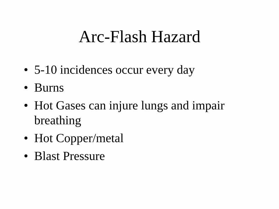
Arc-Flash Hazard
• 5-10 incidences occur every day
• Burns
• Hot Gases can injure lungs and impair
breathing
• Hot Copper/metal
• Blast Pressure

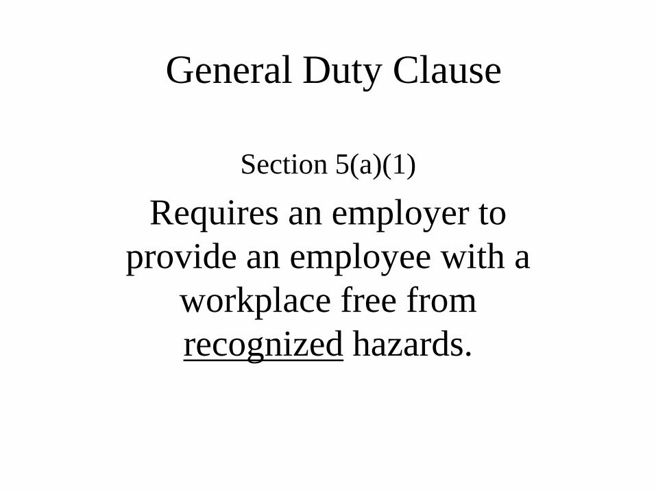
General Duty Clause
Section 5(a)(1)
Requires an employer to
provide an employee with a
workplace free from
recognized hazards.
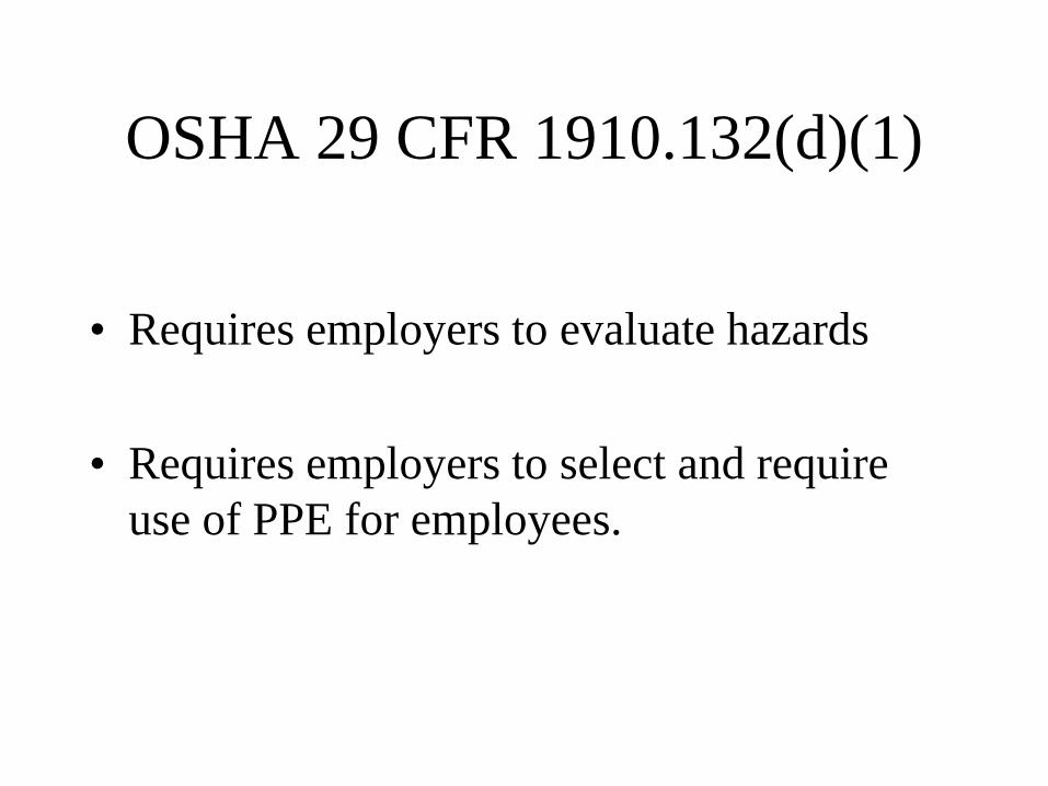
OSHA 29 CFR 1910.132(d)(1)
• Requires employers to evaluate hazards
• Requires employers to select and require
use of PPE for employees.
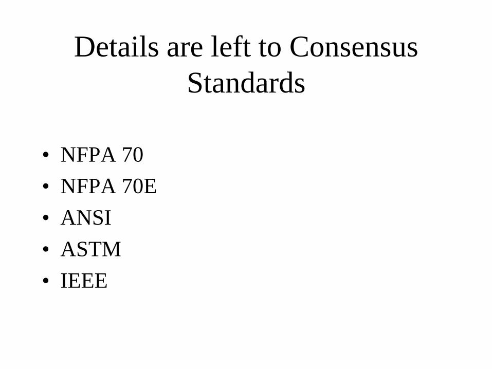
Details are left to Consensus
Standards
• NFPA 70
• NFPA 70E
• ANSI
• ASTM
• IEEE
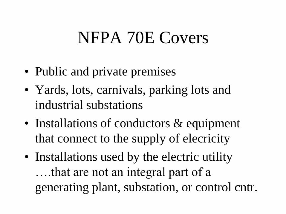
NFPA 70E Covers
• Public and private premises
• Yards, lots, carnivals, parking lots and
industrial substations
• Installations of conductors & equipment
that connect to the supply of elecricity
• Installations used by the electric utility
….that are not an integral part of a
generating plant, substation, or control cntr.
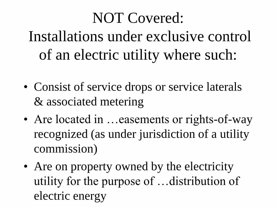
NOT Covered:
Installations under exclusive control
of an electric utility where such:
• Consist of service drops or service laterals
& associated metering
• Are located in …easements or rights-of-way
recognized (as under jurisdiction of a utility
commission)
• Are on property owned by the electricity
utility for the purpose of …distribution of
electric energy

NESC 410
• Assessment of the system is required.
• If >2 cal/cm2, clothing system adequate for the anticipated level of arc energy.
• For voltages >1000 Volts, effective arc rating of clothing system determined from Table 410-1 & 410-2 or Arc Flash Analysis
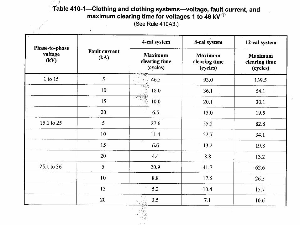

Systems Below 1000 Volts
• Engineering controls to limit exposure.
• Clothing system with a minimum 4
cal/cm2
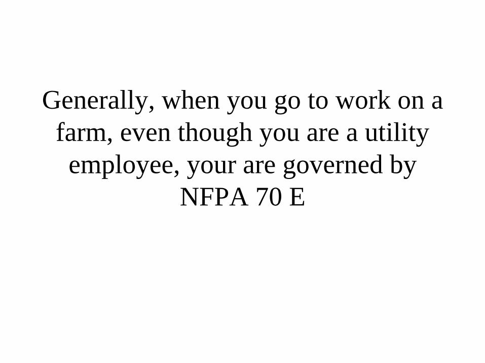
Generally, when you go to work on a
farm, even though you are a utility
employee, your are governed by
NFPA 70 E

Best Practice - De-energizeNFPA 70E Article 130.1: All equipment and
circuits shall be put into an electrically safe
condition before working within the Limited
Approach Boundary unless:
• Doing so presents a greater hazard
• Infeasibility
• Less than 50 Volts
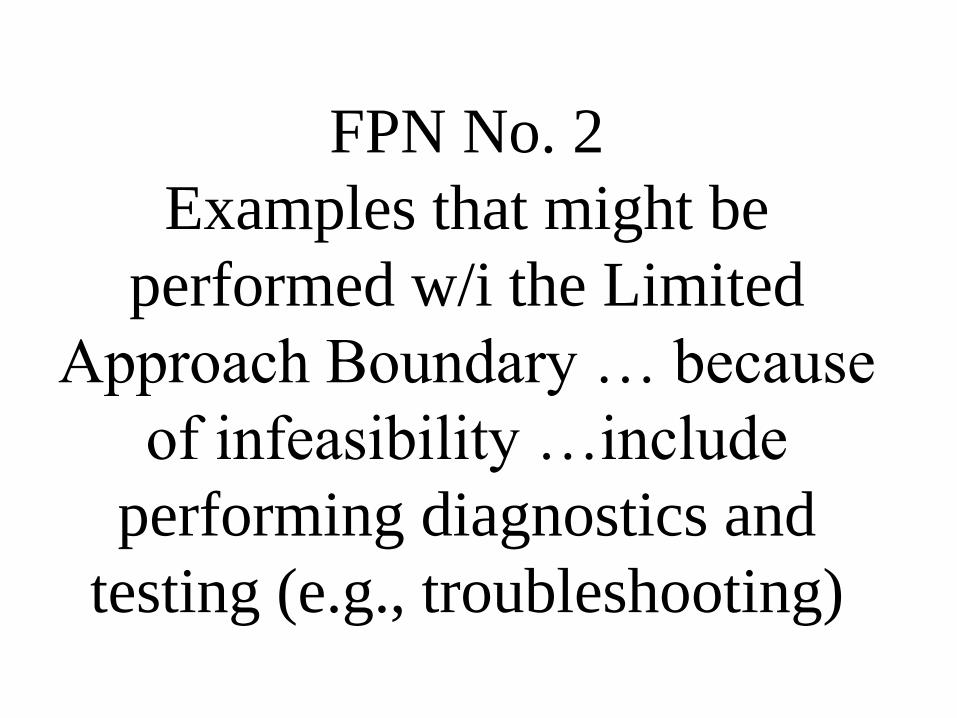
FPN No. 2
Examples that might be
performed w/i the Limited
Approach Boundary … because
of infeasibility …include
performing diagnostics and
testing (e.g., troubleshooting)
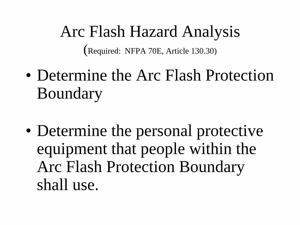
Arc Flash Hazard Analysis(Required: NFPA 70E, Article 130.30)
• Determine the Arc Flash Protection Boundary
• Determine the personal protective equipment that people within the Arc Flash Protection Boundary shall use.
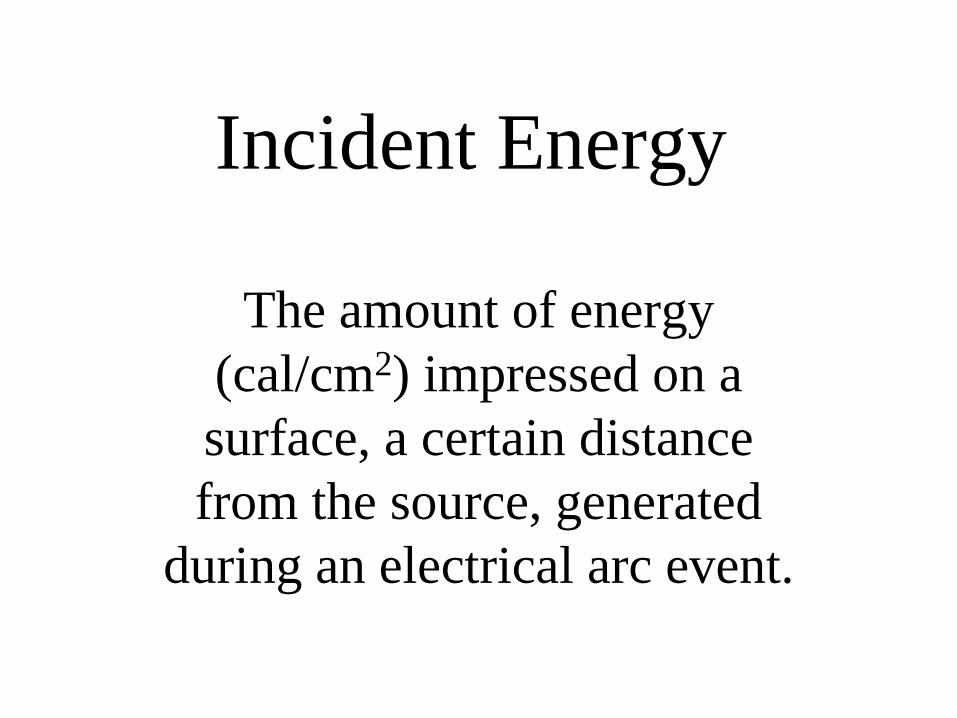
Incident Energy
The amount of energy
(cal/cm2) impressed on a
surface, a certain distance
from the source, generated
during an electrical arc event.

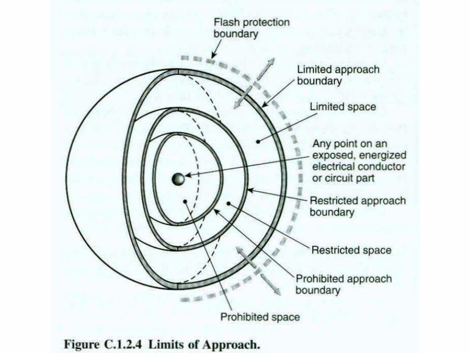
Flash Protection Boundary
An approach limit at a
distance from exposed live
parts within which a person
could receive a 2nd degree
burn if an electrical fault were
to occur. (1.2 cal/cm2)

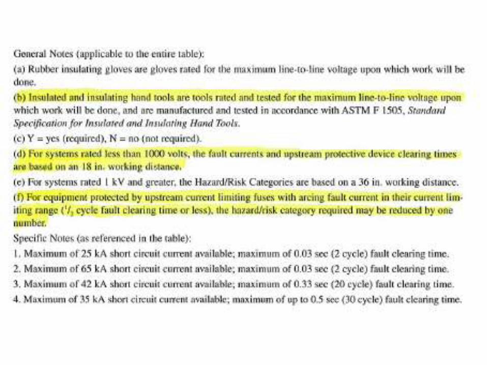
Flash Hazard Analysis (130.3)
For systems 600 Volts or less, the
flash protection boundary shall be
4 feet. (Assumes 2 cycle clearing
time and 50 kA ASCC or any
combination not exceeding 100
kA Cycles.
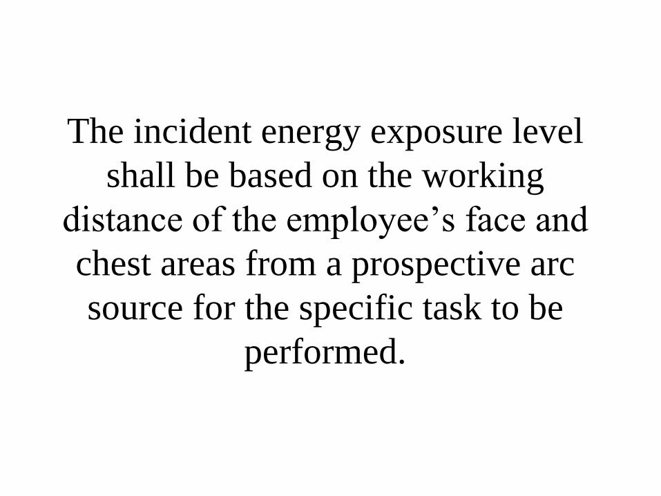
The incident energy exposure level
shall be based on the working
distance of the employee’s face and
chest areas from a prospective arc
source for the specific task to be
performed.
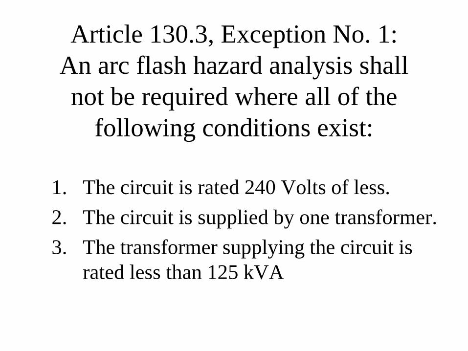
Article 130.3, Exception No. 1:
An arc flash hazard analysis shall
not be required where all of the
following conditions exist:
1. The circuit is rated 240 Volts of less.
2. The circuit is supplied by one transformer.
3. The transformer supplying the circuit is
rated less than 125 kVA

Equation of Arc in a Cubic Box
• DB = distance from arc electrodes, inches (for distances 18
in. and greater)
• tB = arc duration, seconds (cycles/60 cycles)
• F = bolted fault short circuit current, in kA (for the range
of 16 to 50 kA)
• EMB = 1038.7 x DB-1.4738 x tA x (0.0093 x F2 – 0.3453 x F +
5.9675)
• EMB = maximum 20 in cubic box incident energy
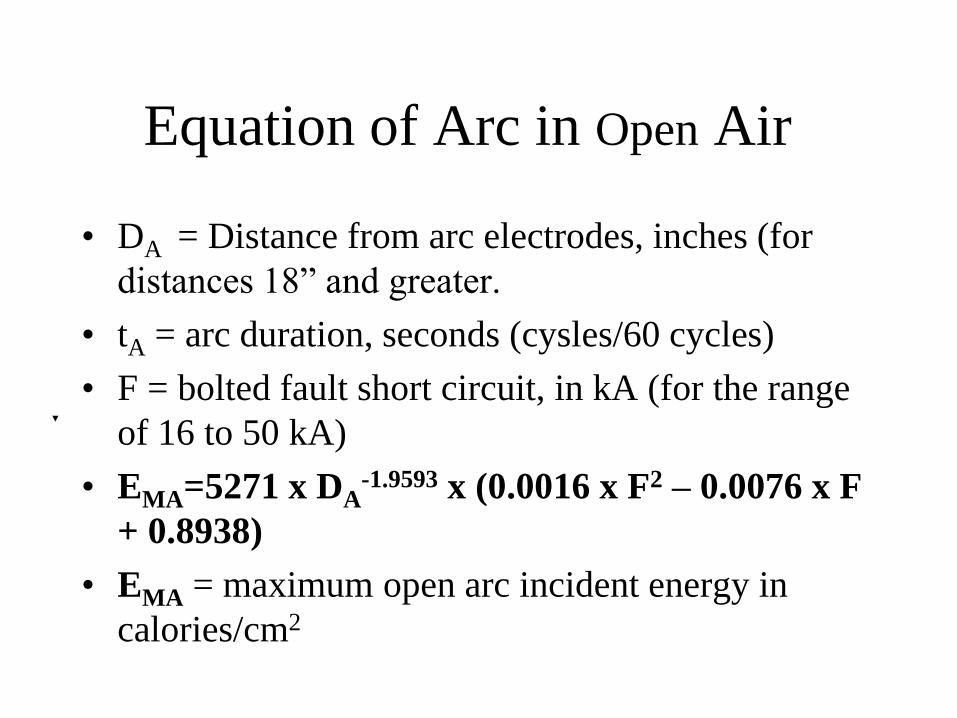
Equation of Arc in Open Air
• DA = Distance from arc electrodes, inches (for
distances 18” and greater.
• tA = arc duration, seconds (cysles/60 cycles)
• F = bolted fault short circuit, in kA (for the range
of 16 to 50 kA)
• EMA=5271 x DA-1.9593 x (0.0016 x F2 – 0.0076 x F
+ 0.8938)
• EMA = maximum open arc incident energy in
calories/cm2
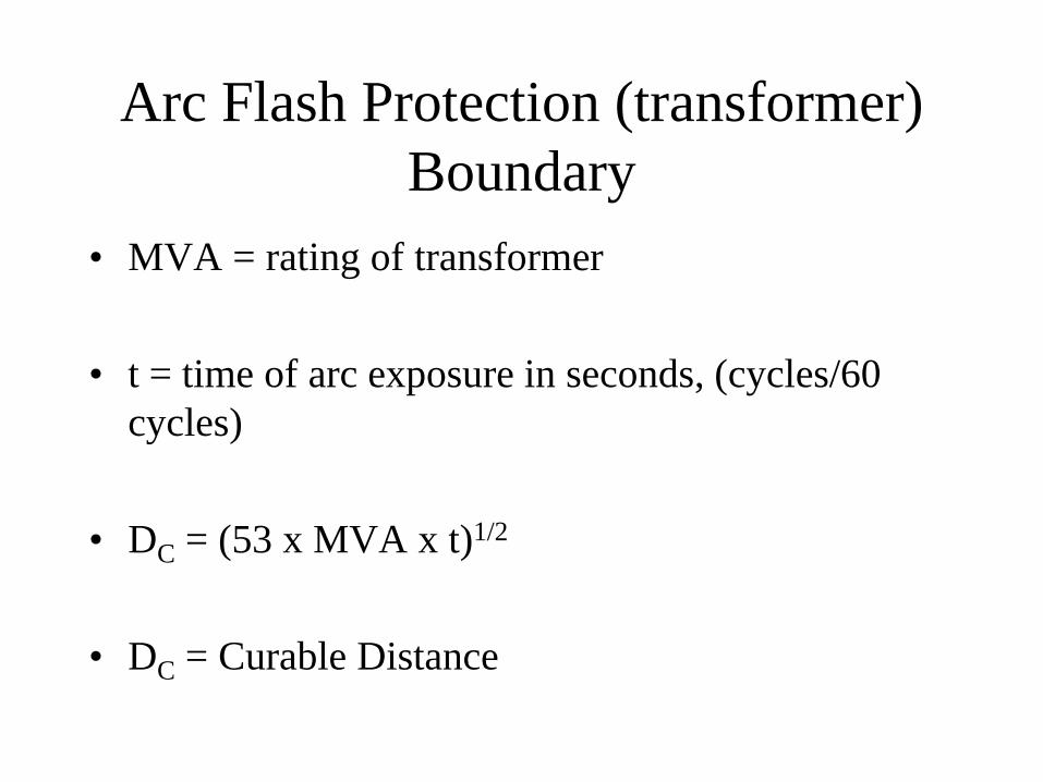
Arc Flash Protection (transformer)
Boundary
• MVA = rating of transformer
• t = time of arc exposure in seconds, (cycles/60
cycles)
• DC = (53 x MVA x t)1/2
• DC = Curable Distance
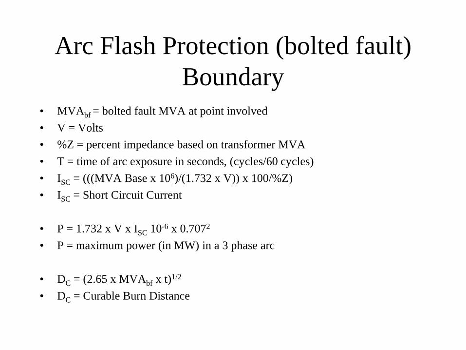
Arc Flash Protection (bolted fault)
Boundary• MVAbf = bolted fault MVA at point involved
• V = Volts
• %Z = percent impedance based on transformer MVA
• T = time of arc exposure in seconds, (cycles/60 cycles)
• ISC = (((MVA Base x 106)/(1.732 x V)) x 100/%Z)
• ISC = Short Circuit Current
• P = 1.732 x V x ISC 10-6 x 0.7072
• P = maximum power (in MW) in a 3 phase arc
• DC = (2.65 x MVAbf x t)1/2
• DC = Curable Burn Distance
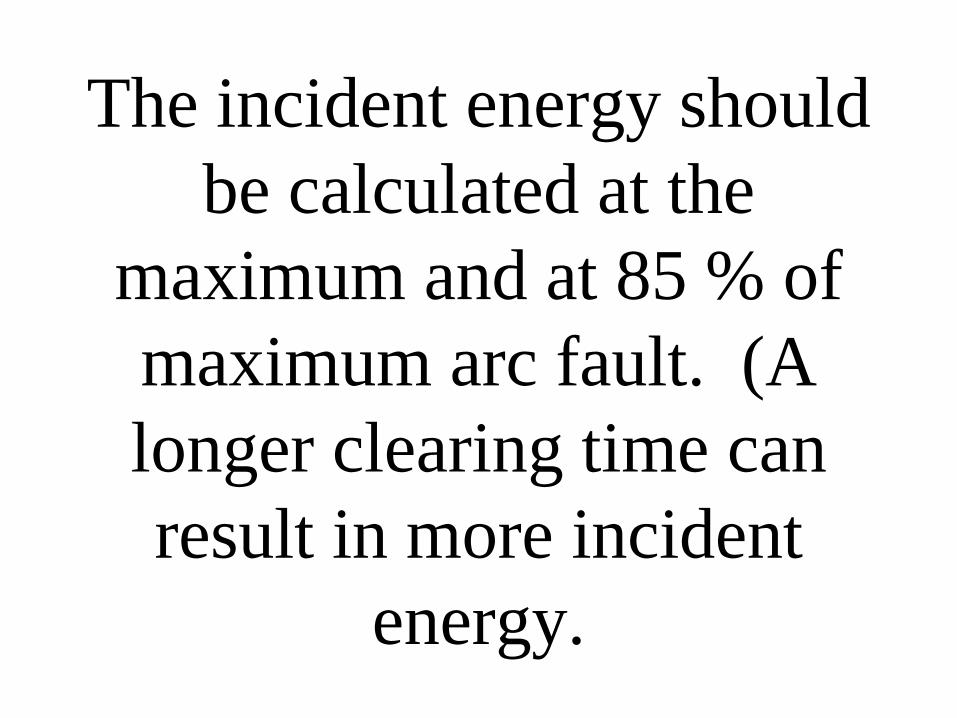
The incident energy should
be calculated at the
maximum and at 85 % of
maximum arc fault. (A
longer clearing time can
result in more incident
energy.

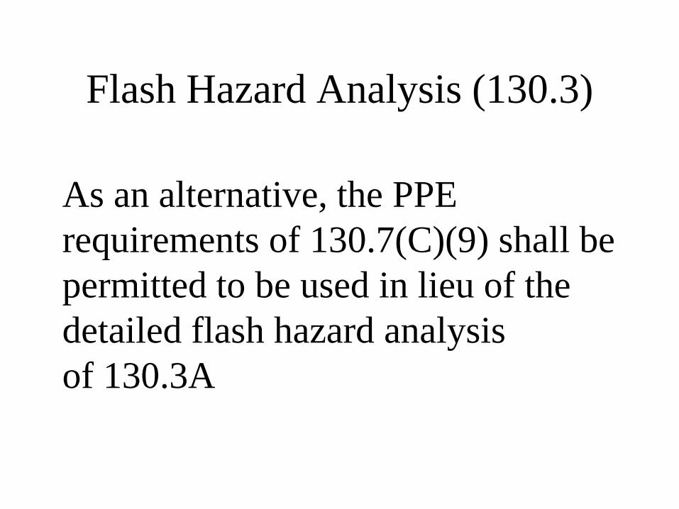
Flash Hazard Analysis (130.3)
As an alternative, the PPE
requirements of 130.7(C)(9) shall be
permitted to be used in lieu of the
detailed flash hazard analysis
of 130.3A
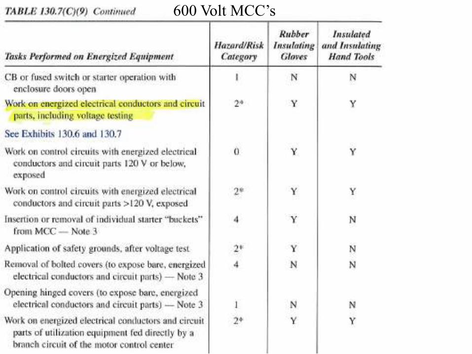
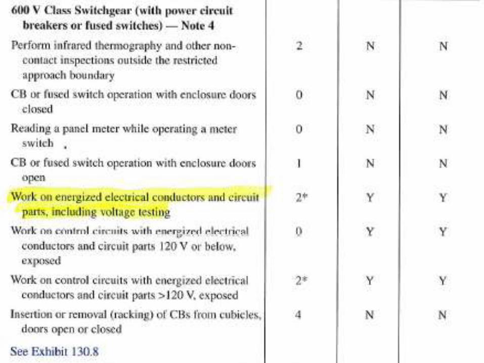
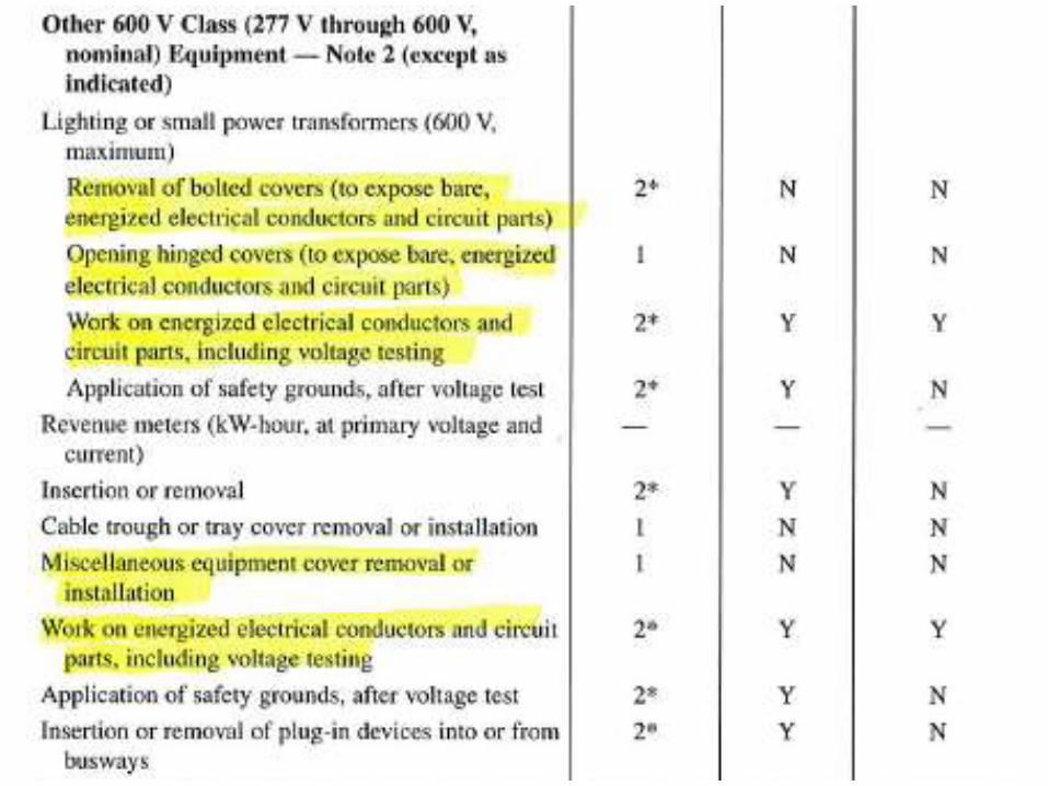
600 Volt MCC’s
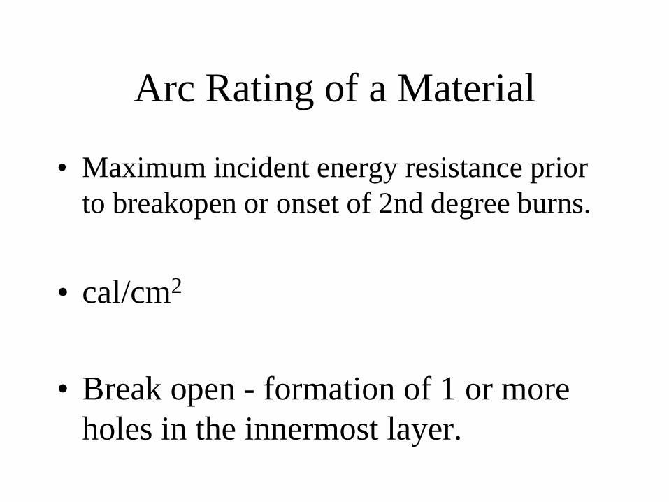
Arc Rating of a Material
• Maximum incident energy resistance prior
to breakopen or onset of 2nd degree burns.
• cal/cm2
• Break open - formation of 1 or more
holes in the innermost layer.
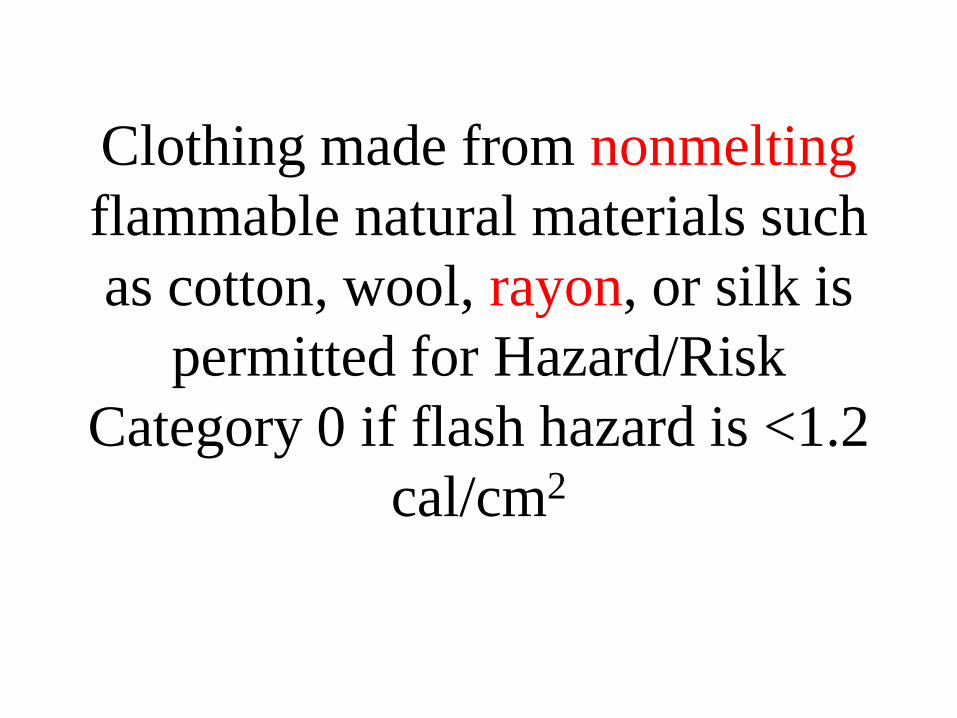
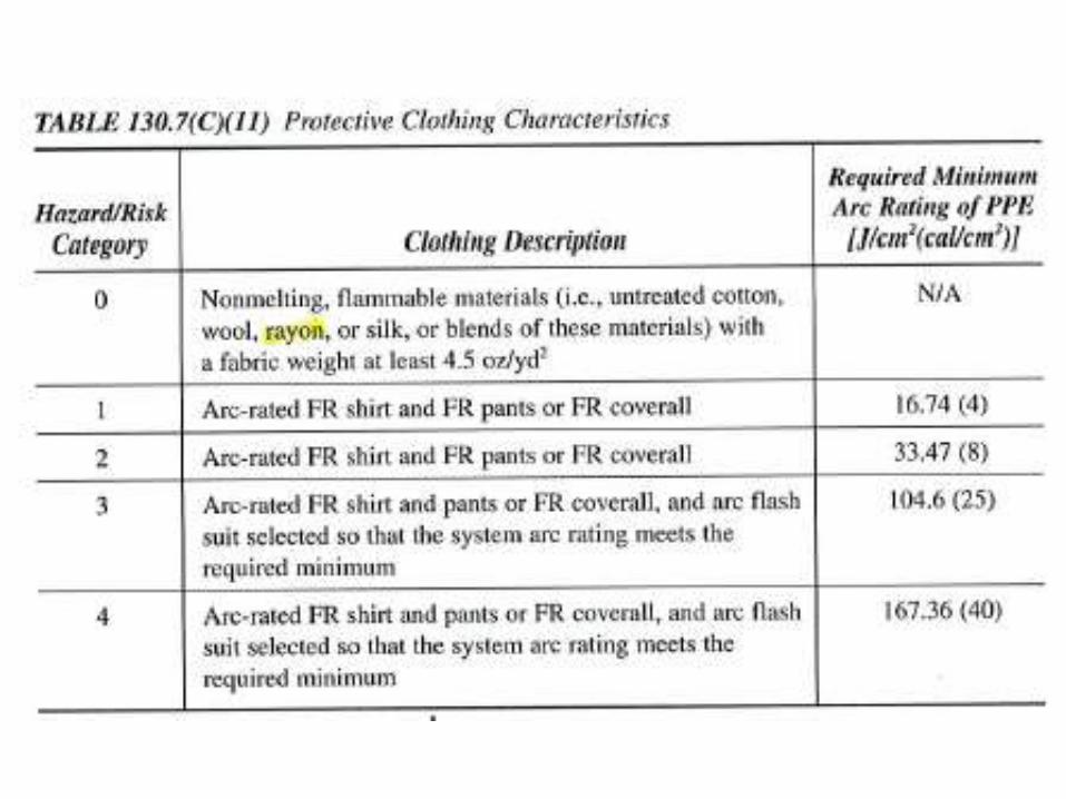
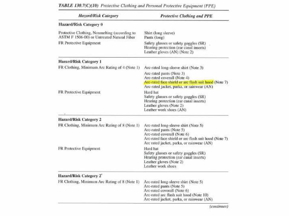
Clothing made from nonmelting
flammable natural materials such
as cotton, wool, rayon, or silk is
permitted for Hazard/Risk
Category 0 if flash hazard is <1.2
cal/cm2
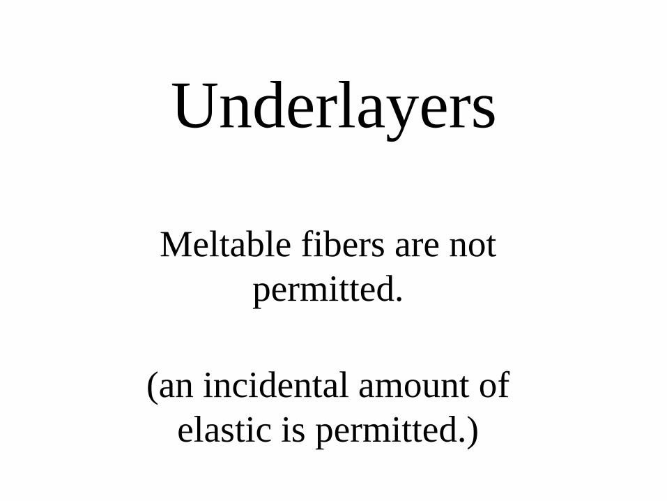
Underlayers
Meltable fibers are not
permitted.
(an incidental amount of
elastic is permitted.)
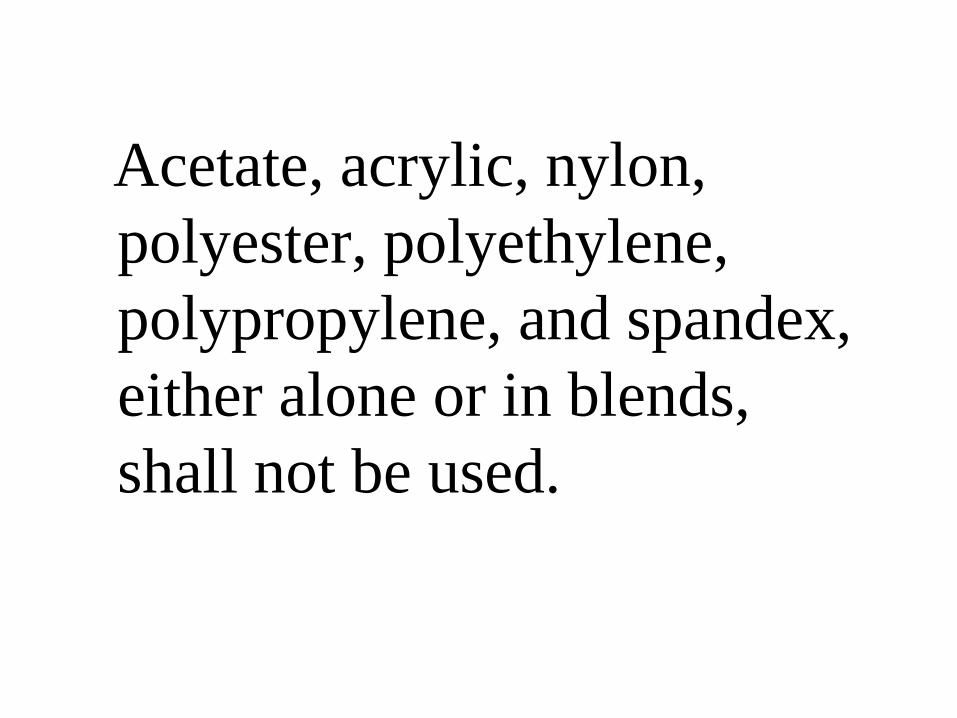
Acetate, acrylic, nylon,
polyester, polyethylene,
polypropylene, and spandex,
either alone or in blends,
shall not be used.
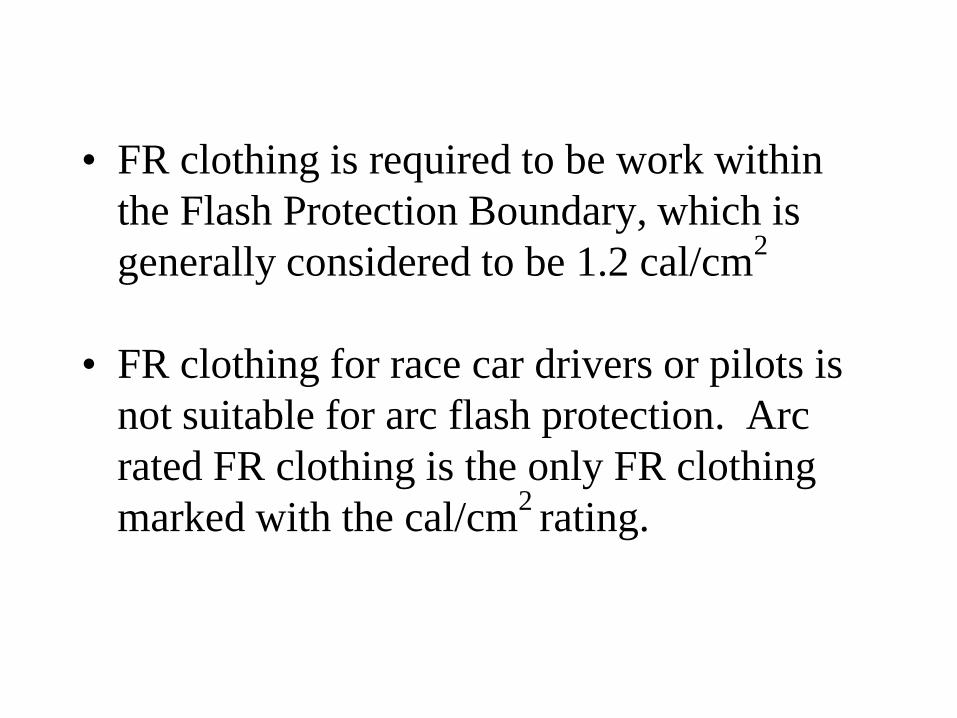
• FR clothing is required to be work within
the Flash Protection Boundary, which is
generally considered to be 1.2 cal/cm2
• FR clothing for race car drivers or pilots is
not suitable for arc flash protection. Arc
rated FR clothing is the only FR clothing
marked with the cal/cm2 rating.


Clothing and other apparel (hair nets, hard hat liners) made from materials that do not meet the requirements of 130.7(C)(14) regarding melting, or made from materials that do not meet the flammability requirements shall not be permitted.
Foot Protection
• Shoes with an arc rating are not available.
• Foot Protection. Heavy-duty leather work shoes
provide some arc flash protection to the feet and
shall be used in all tasks in Hazard/Risk Category
2 and higher and in all exposures greater than 4
cal/cm2.
• An incidental amount of elastic used on
nonmelting fabric underwear or socks shall be
permitted.
Hands
• No method exists for determining the
degree of exposure for a worker’s hands.
• Leather of FR gloves shall be worn where
required for arc flash protection.
• Where insulating rubber gloves are used for
shock protection, leather protectors shall be
worn over the rubber gloves.
Safety glasses must be
worn under the face
shield or viewing
window.
Outer Layers
Garments worn as outer
layers over FR clothing,
(jackets or rain wear) must
also be FR clothing.
Exposure of more than 40
cal/cm?
• task must not be performed until and electrically safe work condition exists
• FR clothing with a very high incident energy rating might me needed to perform the steps necessary to establish an electrically safe condition
• This is the only task that should be accomplished with the equipment energized

• Inspection
• Manufacturer’s Instructions.
• Storage
• Cleaning
Care and Maintenance of FR
Clothing and FR Arc Flash Suits


Other Personal Protective
Equipment
• Eye protection
• Head protection
• Conductive Articles not worn
• Face shields w/o Arc rating shall not be
used.
• Eye protection always be worn under face
shields or hoods.
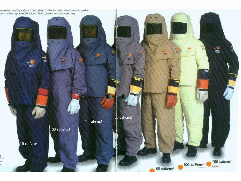
15 cal/cm2
25 cal/cm2
40 cal/cm250 cal/cm2
Proper PPE
• Does not guarantee the worker will remain
injury free
• The purpose is to reduce death
• Burns to the hands and arms aren’t
considered life threatening

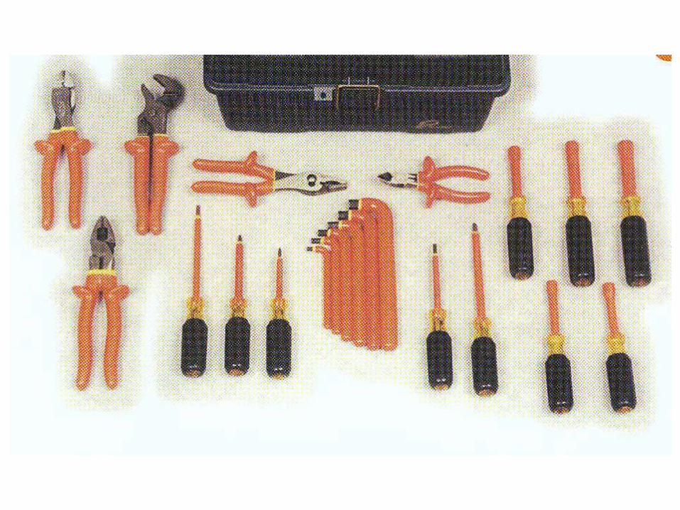
Insulated Tools
Employees shall use
insulated tools and/or
handling equipment when
working inside the limited
approach boundary.(Must be marked with a voltage rating.)

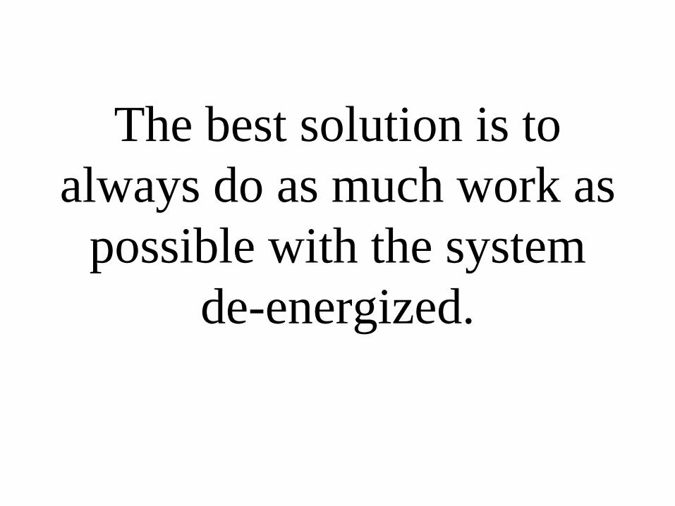
The best solution is to
always do as much work as
possible with the system
de-energized.
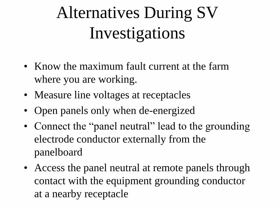
Alternatives During SV
Investigations
• Know the maximum fault current at the farm
where you are working.
• Measure line voltages at receptacles
• Open panels only when de-energized
• Connect the “panel neutral” lead to the grounding
electrode conductor externally from the
panelboard
• Access the panel neutral at remote panels through
contact with the equipment grounding conductor
at a nearby receptacle
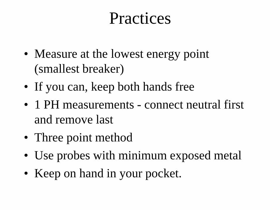
Practices
• Measure at the lowest energy point
(smallest breaker)
• If you can, keep both hands free
• 1 PH measurements - connect neutral first
and remove last
• Three point method
• Use probes with minimum exposed metal
• Keep on hand in your pocket.
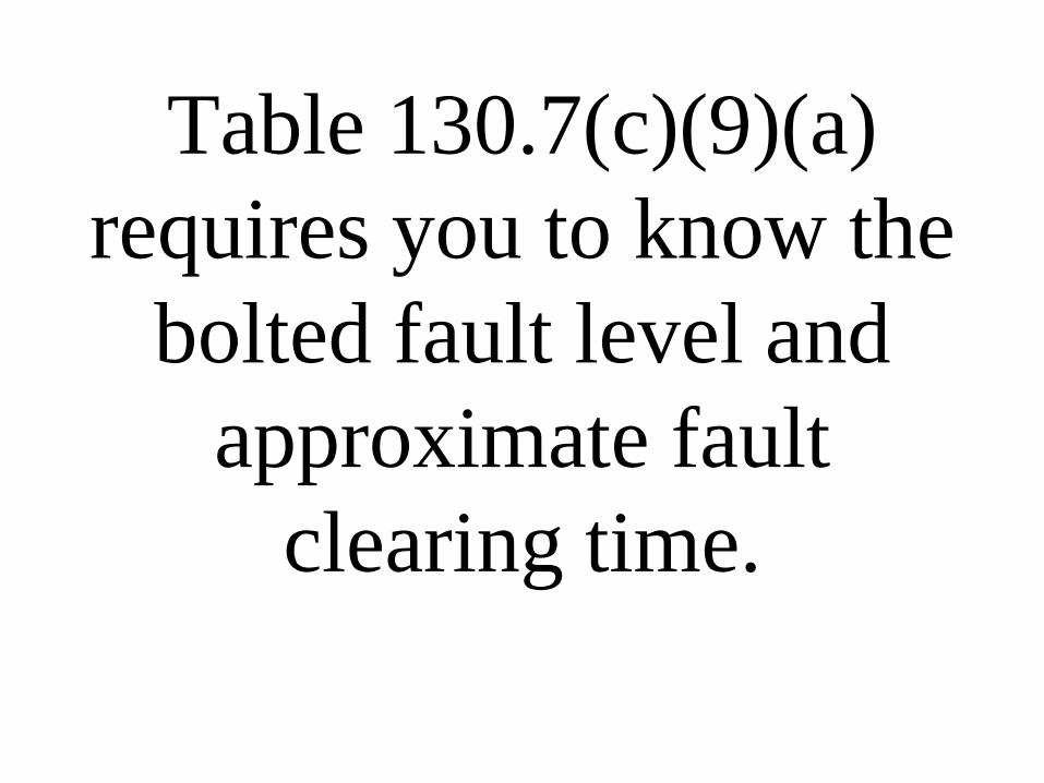
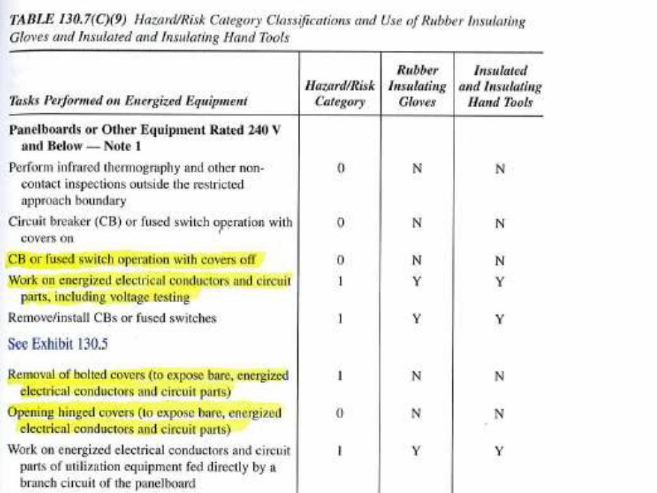
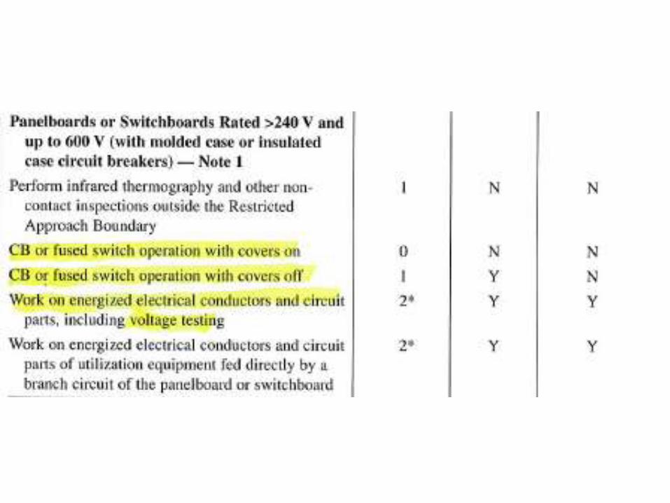
Table 130.7(c)(9)(a)
requires you to know the
bolted fault level and
approximate fault
clearing time.
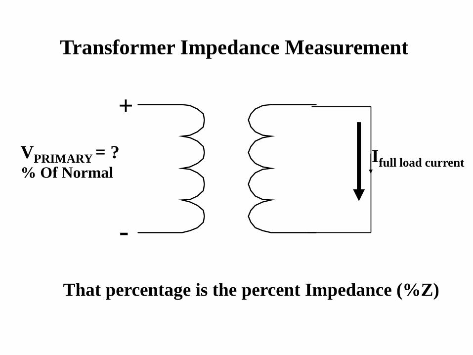
VPRIMARY = ?% Of Normal
Transformer Impedance Measurement
Ifull load current
+
-
That percentage is the percent Impedance (%Z)

VPRIMARY = Normal
Transformer Available Short Circuit Current
IShort Circuit
+
-
ASSC = Ifull load current / %Z
100

OH XFMR Size Sec. Volt. FL Amps %Z ASSC
15 120/240 62.5 1.5 4166
25 120/240 104 1.5 6933
50 120/240 208 1.5 13867
100 120/240 417 2 20850
167 120/240 696 2 34800


Other
Rules

Equipment Contact
Employees standing on the
ground shall not contact the
vehicle or mechanical
equipment or any of its
attachments.

Equipment Grounding
Barricade or insulate to
protect employees from
hazardous step and touch
potentials.
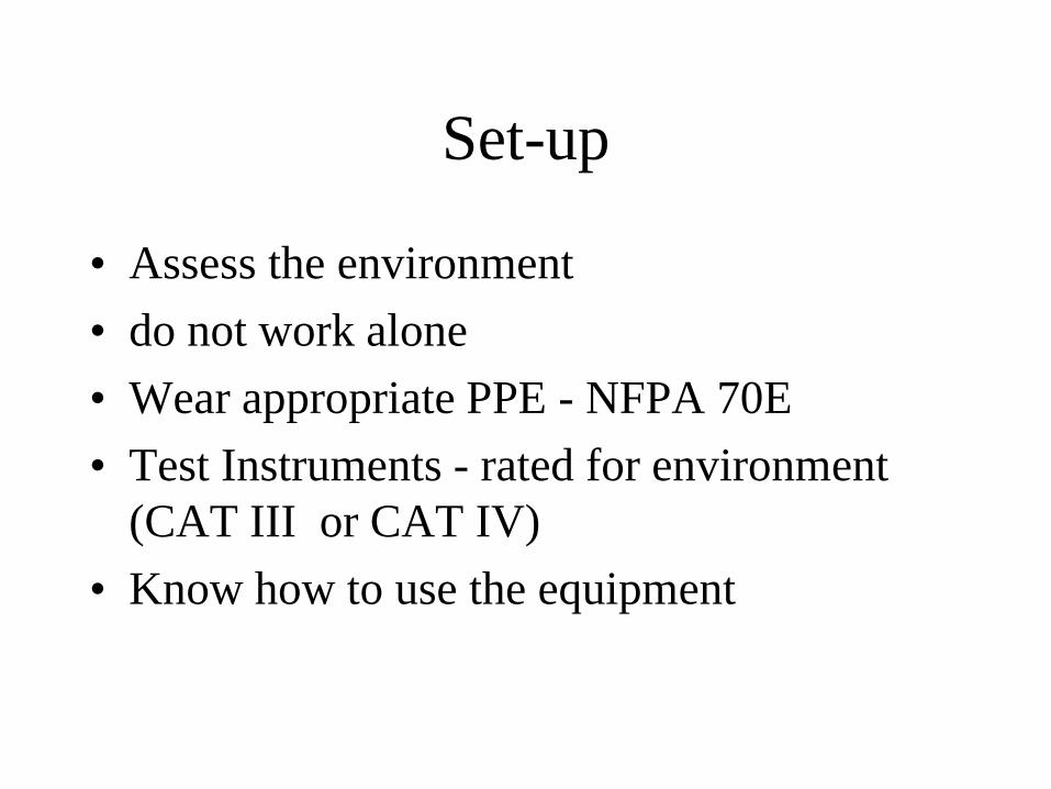
Set-up
• Assess the environment
• do not work alone
• Wear appropriate PPE - NFPA 70E
• Test Instruments - rated for environment
(CAT III or CAT IV)
• Know how to use the equipment

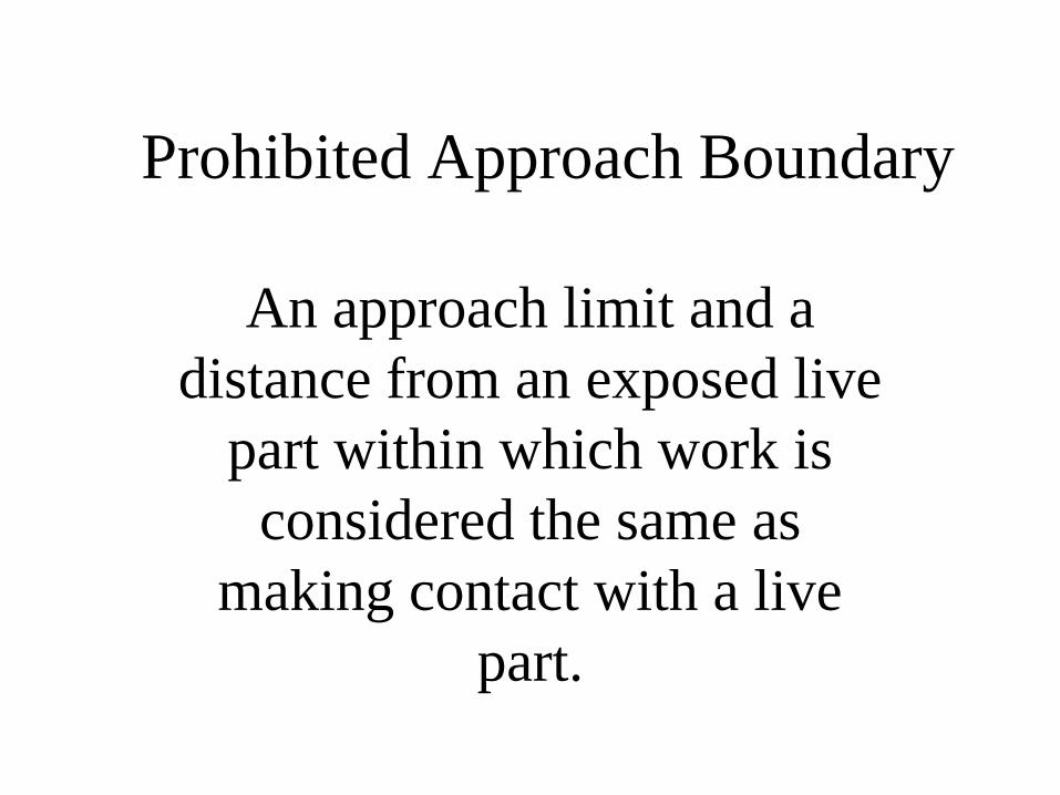
Prohibited Approach Boundary
An approach limit and a
distance from an exposed live
part within which work is
considered the same as
making contact with a live
part.
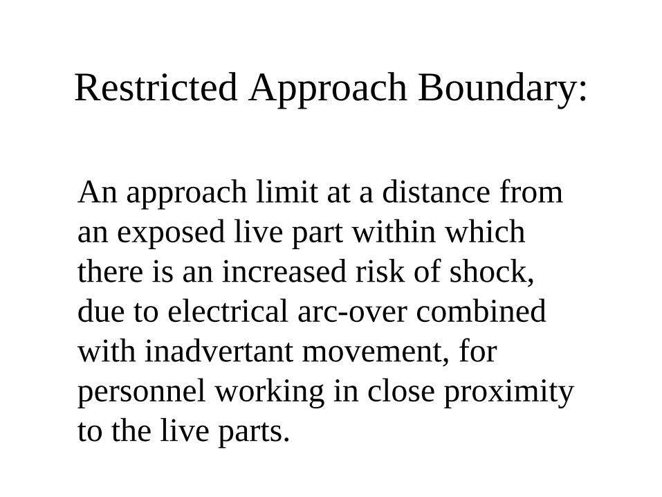
Restricted Approach Boundary:
An approach limit at a distance from
an exposed live part within which
there is an increased risk of shock,
due to electrical arc-over combined
with inadvertant movement, for
personnel working in close proximity
to the live parts.

Limited Approach Boundary
An approach limit at
distance from an exposed
live part within which a
shock hazard exists.
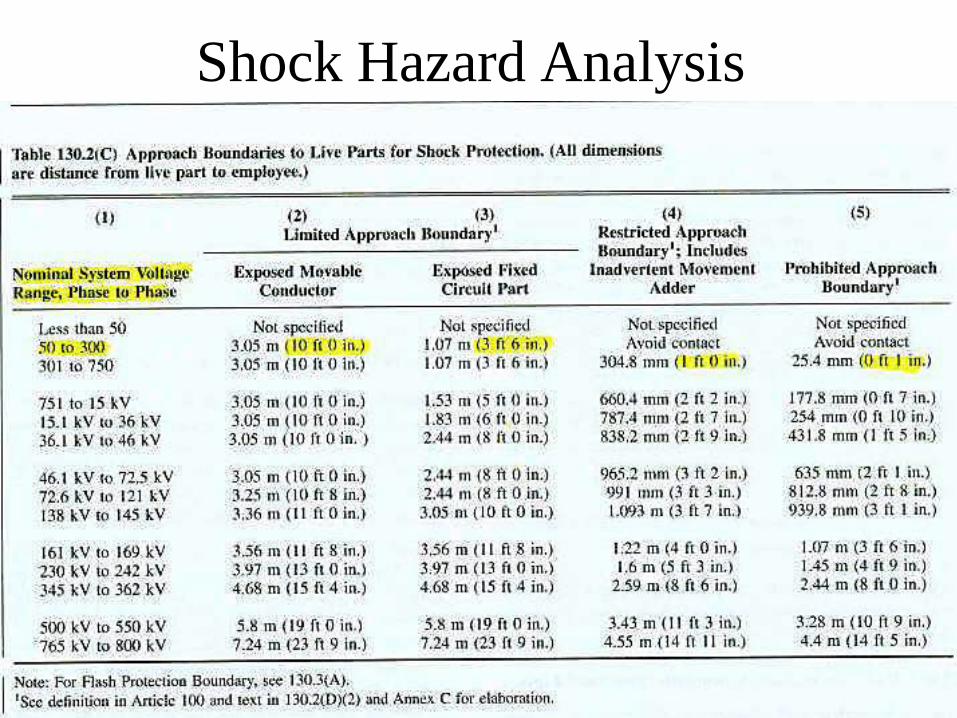
Shock Hazard Analysis