Aviation Rulemaking Advisory Committee (ARAC) Transport - FAA

10551 Federal Register / Vol. 75, No. 44 / Monday, March 8, 2010 / Notices
1 There are no known mileposts associated with the line.
Transportation Board (Board) a petition under U.S.C. 10502 for exemption from the provisions of 49 U.S.C. 10903 to discontinue overhead trackage rights over approximately 3 miles of rail line owned by Peoria and Pekin Union Railway Company, between Bridge Junction in Peoria and P&PU Junction in East Peoria, in Peoria and Tazewell Counties, IL.1 The line traverses United States Postal Service Zip Codes 61602 and 61611.
The interest of railroad employees will be protected by the conditions set forth in Oregon Short Line R. Co.— Abandonment—Goshen, 360 I.C.C. 91 (1979).
By issuance of this notice, the Board is instituting an exemption proceeding pursuant to 49 U.S.C. 10502(b). A final decision will be issued by June 4, 2010.
Because this is a discontinuance proceeding and not an abandonment, trail use/rail banking and public use conditions are not appropriate. Similarly, no environmental or historic documentation is required under 49 CFR 1105.6(c)(2) and 1105.8(b).
Any offer of financial assistance (OFA) for subsidy under 49 CFR 1152.27(b)(2) will be due no later than 10 days after service of a decision granting the petition for exemption. Each OFA must be accompanied by the filing fee, which is currently set at $1,500. See 49 CFR 1002.2(f)(25).
All filings in response to this notice must refer to STB Docket No. AB–6 (Sub-No. 470X) and must be sent to: (1) Surface Transportation Board, 395 E Street, SW., Washington, DC 20423– 0001; and (2) Karl Morell, 1455 F Street, NW., Suite 225, Washington, DC 20005. Replies to the petition are due on or before March 29, 2010.
Persons seeking further information concerning discontinuance procedures may contact the Board’s Office of Public Assistance, Governmental Affairs, and Compliance at (202) 245–0238 or refer to the full abandonment and discontinuance regulations at 49 CFR part 1152. Questions concerning environmental issues may be directed to the Board’s Section of Environmental Analysis (SEA) at (202) 245–0305. [Assistance for the hearing impaired is available through the Federal Information Relay Service (FIRS) at 1–800–877–8339.]
Board decisions and notices are available on our Web site at ‘‘WWW.STB.DOT.GOV.’’
Decided: March 4, 2010.
By the Board, Rachel D. Campbell, Director, Office of Proceedings. Kulunie L. Cannon, Clearance Clerk. [FR Doc. 2010–4953 Filed 3–5–10; 8:45 am]
BILLING CODE 4915–01–P
DEPARTMENT OF TRANSPORTATION
Surface Transportation Board
[STB Ex Parte No. 670 (Sub-No. 1)]
Notice of Rail Energy Transportation Advisory Committee Meeting
AGENCY: Surface Transportation Board. ACTION: Notice of Rail Energy Transportation Advisory Committee Meeting.
SUMMARY: Notice is hereby given of a meeting of the Rail Energy Transportation Advisory Committee (RETAC), pursuant to section 10(a)(2) of the Federal Advisory Committee Act, Public Law No. 92–463, as amended (5 U.S.C., App. 2). DATES: The meeting will be held on Tuesday, March 23, 2010, beginning at 2 p.m., E.D.T. ADDRESSES: The meeting will be held in the Hearing Room on the first floor of the Surface Transportation Board’s headquarters at Patriot’s Plaza, 395 E Street, SW., Washington, DC 20423– 0001.
FOR FURTHER INFORMATION CONTACT: Scott M. Zimmerman (202) 245–0202. Assistance for the hearing impaired is available through the Federal Information Relay Service (FIRS) at: (800) 877–8339. SUPPLEMENTARY INFORMATION: RETAC arose from a proceeding instituted by the Board, in Establishment of a Rail Energy Transportation Advisory Committee, STB Ex Parte No. 670. RETAC was formed to provide advice and guidance to the Board, and to serve as a forum for discussion of emerging issues regarding the transportation by rail of energy resources, particularly, but not necessarily limited to, coal, ethanol, and other biofuels. The purpose of this meeting is to continue discussions regarding issues such as rail performance, capacity constraints, infrastructure planning and development, and effective coordination among suppliers, carriers, and users of energy resources. Potential agenda items include updates from the RETAC subcommittees (Best Practices, Capacity Planning, Communication, and Performance Measures), a briefing by the Energy Information Administration on its Annual Energy Outlook 2010, and
a briefing by Christensen Associates on its updated study of competition in the railroad industry.
The meeting, which is open to the public, will be conducted pursuant to RETAC’s charter and Board procedures. Further communications about this meeting may be announced through the Board’s Web site at http://www.stb.dot.gov.
This action will not significantly affect either the quality of the human environment or the conservation of energy resources.
Authority: 49 U.S.C. 721, 49 U.S.C. 11101; 49 U.S.C. 11121.
Decided: March 3, 2010. By the Board, Rachel D. Campbell,
Director, Office of Proceedings. Jeffrey Herzig, Clearance Clerk. [FR Doc. 2010–4863 Filed 3–5–10; 8:45 am]
BILLING CODE 4915–01–P
DEPARTMENT OF TRANSPORTATION
Federal Aviation Administration
Aviation Rulemaking Advisory Committee Meeting on Transport Airplane and Engine Issues
AGENCY: Federal Aviation Administration (FAA), DOT. ACTION: Notice of public meeting.
SUMMARY: This notice announces a public meeting of the FAA’s Aviation Rulemaking Advisory Committee (ARAC) to discuss transport airplane and engine (TAE) issues. DATES: The meeting is scheduled for Wednesday, April 14, 2010, starting at 8:30 a.m. Pacific Standard Time. Arrange for oral presentations by April 1, 2010. ADDRESSES: FAA–Northwest Mountain Region Office, Transport Standards Staff conference room, 1601 Lind Ave., SW., Renton, WA 98057. FOR FURTHER INFORMATION CONTACT: Ralen Gao, Office of Rulemaking, ARM– 209, FAA, 800 Independence Avenue, SW., Washington, DC 20591, Telephone (202) 267–3168, Fax (202) 267–5075, or e-mail at [email protected]. SUPPLEMENTARY INFORMATION: Pursuant to Section 10(a)(2) of the Federal Advisory Committee Act (Pub. L. 92– 463; 5 U.S.C. app. III), notice is given of an ARAC meeting to be held April 14, 2010.
The agenda for the meeting is as follows:
• Opening Remarks, Review Agenda and Minutes.
• FAA Report.
VerDate Nov<24>2008 17:12 Mar 05, 2010 Jkt 220001 PO 00000 Frm 00097 Fmt 4703 Sfmt 4703 E:\FR\FM\08MRN1.SGM 08MRN1srob
inso
n on
DS
KH
WC
L6B
1PR
OD
with
NO
TIC
ES

10552 Federal Register / Vol. 75, No. 44 / Monday, March 8, 2010 / Notices
• Airplane-level Safety Analysis WG Report.
• Task 4 Status/Vote. • EXCOM Report. • Transport Canada Report. • Airworthiness Assurance HWG
Report. • Avionics HWG Report. • Any Other Business. • Action Item Review. Attendance is open to the public, but
will be limited to the availability of meeting room space. Please confirm your attendance with the person listed in the FOR FURTHER INFORMATION CONTACT section no later than April 1, 2010. Please provide the following information: Full legal name, country of citizenship, and name of your industry association, or applicable affiliation. If you are attending as a public citizen, please indicate so.
For persons participating by telephone, PLEASE CONTACT Ralen Gao by e-mail or phone for the teleconference call-in number and passcode. Anyone calling from outside the Renton, WA, metropolitan area will be responsible for paying long-distance charges.
The public must make arrangements by April 1, 2010, to present oral statements at the meeting. Written statements may be presented to the ARAC at any time by providing 25 copies to the person listed in the FOR FURTHER INFORMATION CONTACT section or by providing copies at the meeting. Copies of the documents to be presented to ARAC may be made available by contacting the person listed in the FOR FURTHER INFORMATION CONTACT section.
If you need assistance or require a reasonable accommodation for the meeting or meeting documents, please contact the person listed in the FOR FURTHER INFORMATION CONTACT section. Sign and oral interpretation, as well as a listening device, can be made available if requested 10 calendar days before the meeting.
Issued in Washington, DC, on March 2, 2010. Pamela Hamilton-Powell, Director, Office of Rulemaking. [FR Doc. 2010–4792 Filed 3–5–10; 8:45 am]
BILLING CODE 4910–13–P
DEPARTMENT OF TRANSPORTATION
Federal Aviation Administration
Sixth Meeting—RTCA Special Committee 217: Joint With EUROCAE WG–44 Terrain and Airport Mapping Databases
AGENCY: Federal Aviation Administration (FAA), DOT.
ACTION: Notice of RTCA Special Committee 217: Joint with EUROCAE WG–44 Terrain and Airport Mapping Databases.
SUMMARY: The FAA is issuing this notice to advise the public of a meeting of RTCA Special Committee 217: Joint with EUROCAE WG–44 Terrain and Airport Mapping Databases. DATES: The meeting will be held on April 12th thru 16th, 2010, at 9 a.m. ADDRESSES: The meeting will be held at Graf-Zeppelin-Haus (http:// www.gzh.de), Kapitan Lehmann Raum, Olgastr. 20, D–88045 Friedrichshafen/ Germany. Contact: Britta Eilmus [email protected] Phone: +49–69–6060–9894, Mobile: +49–179– 789–5474, Fax: +49–7541–282–199 FOR FURTHER INFORMATION CONTACT: RTCA Secretariat, 1828 L Street, NW., Suite 805, Washington, DC 20036–5133; telephone (202) 833–9339; fax (202) 833–9434; Web site http://www.rtca.org. SUPPLEMENTARY INFORMATION: Pursuant to section 10(a)(2) of the Federal Advisory Committee Act (Pub. L. 92– 463, 5 U.S.C., Appendix 2), notice is hereby given for a RTCA Special Committee 217: Joint with EUROCAE WG–44 Terrain and Airport Mapping Databases meeting. The agenda will include:
Monday, April 12
• Opening Plenary Session • Chairmen’s remarks and
introductions • Approve minutes from previous
meeting • Review and approve meeting
agenda • Committee Membership Records • Schedule for this week • Action Item Review • Schedule for next meetings
• Presentations (Not linked to Working Group Activity)
• Tim Roe: FAA activity with taxi route databases, tied to SC–214
• Garry Livack, Update on related Standards activities, i.e. D–NOTAM (Aerodrome), D-Taxi, D-Traffic
• Andre Bourdais, Proposal for Joint Task Force, SC–217/SC–214, data exchange requirements
• Allan Hart, SESAR WP9 • Working Group Report Outs (Status)
• Applications • Data Quality—Non-Numeric
Requirements • Data Quality—Numeric
Requirements • Guidance Materials • Temporality • Content • Connectivity
Tuesday, April 13 • Specific Working Group Sessions
• Connectivity • Content • Applications • Numerical Requirements • Guidance Materials • Data Quality
Wednesday, April 14 • Continuation of Specific Working
Group Sessions (if required)— Committee Coordination
• SC–186 ISRA Review and Response Planning
• SC–214 Requirements Review and Response Planning
Thursday, April 15 • Document Agreements
• DO–272, Revision C • DO–291, Revision B • DO–276, Revision B • Road Map Review
Friday, April 16 • Closing Plenary Session
• Joint RTCA SC–217/EUROCAE WG–44
Attendance is open to the interested public but limited to space availability. With the approval of the chairmen, members of the public may present oral statements at the meeting. Persons wishing to present statements or obtain information should contact the person listed in the FOR FURTHER INFORMATION CONTACT section. Members of the public may present a written statement to the committee at any time.
Issued in Washington, DC, on March 2, 2010 Francisco Estrada C., RTCA Advisory Committee. [FR Doc. 2010–4847 Filed 3–5–10; 8:45 am]
BILLING CODE 4910–13–P
DEPARTMENT OF TRANSPORTATION
Federal Aviation Administration
Noise Exposure Map Notice for Chandler Municipal Airport, Chandler, AZ
AGENCY: Federal Aviation Administration, DOT. ACTION: Notice.
SUMMARY: The Federal Aviation Administration (FAA) announces its determination that the noise exposure maps submitted by City of Chandler, for Chandler Municipal Airport under the provisions of 49 U.S.C. 47501 et seq. (Aviation Safety and Noise Abatement Act) and 14 CFR part 150 are in compliance with applicable requirements.
VerDate Nov<24>2008 17:12 Mar 05, 2010 Jkt 220001 PO 00000 Frm 00098 Fmt 4703 Sfmt 4703 E:\FR\FM\08MRN1.SGM 08MRN1srob
inso
n on
DS
KH
WC
L6B
1PR
OD
with
NO
TIC
ES

1
Aviation Rulemaking Advisory Committee (ARAC) Transport Airplane and Engine (TAE) Issues Area
Meeting Minutes
Date: April 14, 2010 Time: 8:30 AM Location: FAA-Northwest Mountain Region Renton, WA Call to Order /Administrative Reporting Mr. Craig Bolt (TAE Assistant Chair) called the meeting to order at 8:30AM. Mr. Mike Kaszycki (TAE Assistant Executive Director) read the Federal Advisory Committee Act (FACA) statement. Mr. Bolt reviewed the agenda. Item September 23, 2009 TAEIG Meeting
Action Items Status
1. FAA (Mr. Wilborn) took an action item to discover what are the process for review of draft tasking on Low Speed awareness (Federal Register publication for comments, or other means).
CLOSED
2. FAA (Mr. Kaszycki) and AAWG (Mr. Varanasi) to meet and review potential harmonization issues with EASA relating to Aging Aircraft Program. Mr. Kaszycki to update TAEIG at next meeting.
CLOSED
3. AAWG (Mr. Varanasi) to supply Airbus-supplied list of potential additional concerns regarding EASA harmonization.
CLOSED
4. FAA (Mr. Wilborn) to discover what the double asterisks refers to on the FAA project status sheet, and add a column on working methods (if known).
CLOSED
FAA Report Ms. Suzanne Masterson presented this report. (See Handout #1.) Mr. Kaszycki stated that the ARAC comments to the tasking notice for Low Speed Awareness and Alerting has been received, and a corrected version will be published in the Federal Register. He will let commenters know how comments are dispositioned for this tasking.

2
Regarding part 25 draft policy, the comment log with disposition of comments from the review process will be available on RGL when the final policy is posted. Mr. Kaszycki stated that the draft policy statement on engine rotor lock is a collaboration between ANM and ANE, and may be somewhat controversial. Draft ACs and policy may be found on the draft document page on the FAA website, http://www.faa.gov/aircraft/draft_docs/. Regarding harmonization with EASA, the ultimate goal is to produce a common inventory of potential rulemaking projects. This has been somewhat difficult to coordinate, because the FAA rulemaking processes is slightly longer than EASA’s process. The CMR team meeting has just been restarted. Mr. Kaszycki stated that there are three distinct efforts to improve the rulemaking process:
(1) ARM initiated a rulemaking re-engineering refresh in 2009, which is a thorough reconsideration of the FAA’s internal rulemaking processes. However, the resulting changes should not affect ARAC processes. (2) Joe Hawkins has been engaged as consult to ARM and performing a top-down review of ARAC processes. Mr. Bolt and Mr. Kaszycki will meet with him regarding this effort. (3) Mr. Bolt now co-chairs a process-change tasking under EXCOM.
Mr. Kaszycki had reviewed the FAA re-authorization tasking. He stated that there are a number of aviation safety-related rules that will be coming down the pipeline, which may impact ANM priorities down the road. Airplane-level Safety Analysis WG Report Mr. Roger Knepper presented this report. (See Handout #2a & 2b.) Regarding Task 4, Aging and Wear, Mr. Kaszycki wanted clarification that, assuming the proposed changes result in a new amendment, and a manufacturer recommends significant changes, these changes will be applied according to CPR. Mr. Knepper stated that this is correct. Regarding Task 4–Flight and Diversion time, Mr. Keith Barnett asked for clarification of the term “worthy” in the phrase “specific risk concerns worthy of being addressed,” and are there any exceptions. Mr. Knepper responded that all elements that influence the hazard classification are “worthy” and must be considered, without exception. Mr. Ed Wineman further stated that these concerns should be addressed early, in order to establish the criteria for what constitutes significant /non-significant concerns.

3
Regarding Task 4–Latent Failures, Ms. Sarah Knife stated that Mr. Paul Mingler sent Mr. Knepper a letter outlining the cost issue, but it was reduced to a single paragraph in the dissenting section of the final report. Mr. Knepper stated that GE did not submit the standardized form for their cost analysis. Mr. Mingler stated that an engine manufacturer cannot quantify cost specifically related to an as-yet unknown issue that would require additional work, beyond the fact that there would be additional costs. Ms. Knife stated that, depending on the manner of interpretation, compliance to this proposed recommendation would cost manufacturers several million dollars per engine. Mr. Kaszycki asked what would GE’s comment to ARM be, were the FAA to publish this report tomorrow, with a cost analysis consisting with the majority position? Ms. Knife stated that GE would respond with its own cost-cost benefit analysis that show prohibitive costs. Mr. Knepper stated that, if the engine design has already been certified, this recommendation would not require the manufacturer to change the design. Mr. Kaszycki stated that it was his understanding that manufacturers already implement the standards proposed in this recommendation, although they were not required to do so by regulation, and Mr. Wineman agreed that this was the case. Mr. C. W. Roberts and Ms. Knife spoke in further detail on the potentially large costs of complying with the recommendation. A concern arose about the term “on the order of” being in the rule text. Mr. Kaszycki responded that regulatory language is an Aviation General Council (AGC) concern, which is properly addressed during the rulemaking process. Mr. Wineman stated that, while “probable” was the correct term and used correctly in the accompanying ACs, the Group did not want to use it in the report because it was used in the rule text to refer to something else. As a compromise, “on the order of” became the next best term. Regarding AC 25.629-1A, § 5.c.(3)(c), Mr. Knepper stated that Transport Canada provided a comment that echoed this concern: OEMs are concerned that, when a qualitative statement in the rule text replaces a defined minimum, standards would change depending on whichever person is doing the evaluation. Regarding § 25.671(c)(3), Mr. Wineman stated that the FAA was originally concerned about changing this regulation at all. The Group had taken the FAA’s concern into consideration, and had provided legitimate bases for the recommended changes in the final report. Ms. Knife stated that GE dissents to § 25.1309 and AC 25.1309. There followed a detailed technical discussion over potential situations of how the regulation could be interpreted and complied with. As a wrap up, Mr. Knepper stated that all positions and rationale, including dissenting opinions, are covered in the final report.
4
The Committee then voted on whether to accept the ASAWG final report. Result of the vote—all Yes. The approved report will be transmitted to the FAA, containing some remaining issues to be highlighted in the transmittal letter. A question arose regarding how would the rule text be implemented, given the conflicts between majority and minority positions. Mr. Wineman stated that the Group provided a proposed preamble, containing a record of the conflict and issues that arose during discussion. EXCOM Report Mr. Craig Bolt presented this report (see Handout #3). The Process Improvement Working Group received hundreds of responses and comments to the survey. The team will meet in Seattle to review survey results. The final report is due in September 2010. Pamela Hamilton, Director of Rulemaking, forwarded the FAA/EASA Fall CMR meeting presentation for reference (see Handout #3a). Transport Canada Report Mr. Oliver Rusch presented this report (see Handout #4). Airworthiness Assurance HWG Report Mr. Rao Varanasi presented this report (see Handout #5). The Working Group asked to extend the scheduled completion of Phase II to December 2010, rather than December 2009. Although the task was completed in December 2009. However, more issues have appeared that merit further discussion. Mr. Kaszycki responded that, to do so, the Working Group would need to delineate all the remaining issues and justify the need for this extension. The FAA will do its best to accommodate, if an extension is justified. Mr. Derosier asked that, given the deadline for Task 4 deadline will be December 2010, are operators still required to comply by December 2010? Mr. Varanasi responded that this extension would not change compliance dates; Task 4 is already completed: the data has already been developed and delivered to all interested parties. The Group seeks the extension primarily so it could be available to provide further help and guidance. Mr. Kaszycki asked a question regarding the last bullet on Page 7, which state “Part 26 Subpart E compliance resulted in a program requiring far more resources than the earlier estimates due to conservative interpretations by the FAA and the DAH.” Mr. Varanasi stated that the FAA and DAH’s interpretation, while necessary, resulted in an extensive list of items that required consideration, greater than the Working Group expected or allotted time for during its planning stages.

5
Mr. Varanasi asked that the FAA provide guidance that part 26 approvals serve as approvals for all AD affected structure where the AD required actions are based on damage tolerance (same as the part 26 rule requirement). Ms. Masterson stated that airworthiness directives (ADs) contained legal requirements which trumped FAA guidance, so guidance would be ineffective for this purpose. This might be an issue that will be resolved differently from AD to AD, and ACO by ACO. Further, part 26 does not override the repeated need for ADs. Mr. Kaszycki stated that he had heard different things about how operators are confused by this issue. ANM will work AFS to resolve this difference, hopefully without having to change the compliance date. Avionics HWG Mr. Clark Badie presented this report. (See Handout #6a, 6b & 6c.) The Working Group has submitted a report, together with two supporting ACs. This closes the Working Group tasking. The appendices include number of issue paper, etc., to provide any guidance not found in the ACs. Mr. Kaszycki stated that the FAA would prefer this Working Group to stay intact for the Low Speed Awareness tasking, despite some concerns over whether this Working Group contains sufficient expertise on this subject. This Group has worked well together in the past, and should be able gather any necessary information and support from other Groups as needs arise. Since tasking points to an obvious vulnerability, it would top the FAA’s priority list in the coming year. Mr. Tom Peters asked whether CAST is working on a problem similar to Low Speed Awareness, called Energy Requirements. Mr. Kaszycki stated that he will make inquiries to CAST. Mr. Kaszycki stated that this tasking contains a potentially controversial aspect in the form of its retro-fit clause. Those with individual interests should please arrange to be involved in this Group, to ensure these interests are well represented. Mr. Kihm stated that Boeing has a few minor issues with the report. He will forward them to Mr. Bolt for further discussion, but this will not interfere with voting. Mr. Barnett stated that Bombardier also has minor issues regarding the HUD AC, and would submit these to Mr. Bolt. A question arose regarding whether future weather /traffic products will be linked to weather centers, and would people on the ground be able to see the same information as the crew in the air? The general response was, this is not an issue that will be considered in this tasking at this time. The Committee voted on whether to accept the AHWG final report. Result of the vote—all Yes.

6
Any Other Business Mr. Jim Hoppins presented the report for AIA Supercooled Large Droplets (SLD) Working Group (see Handout #7). Mr. Kaszycki stated that June 2010 is still the estimated deadline to publish this rule for public comment. Regarding its “potential for reduced regulatory benefits,” the identified issues should only affect the cost of the proposed regulation, rather than reduce its benefits. Action Item Review Item April 14, 2010 TAEIG Meeting Action Items
Status
1. FAA (Suzanne Masterson) to send to TAEIG the FAA comment disposition on low speed awareness tasking.
2. AAWG to provide justification for extension of oversight activities to December 2010.
3. FAA to provide updated tasking for Low Speed Awareness to ARAC concurrent with Federal Register publication.
Closed
4. Clark Badie to provide a current list of Avionics HWG members Closed 5. Boeing and Bombardier to provide comments to AHWG report
for inclusion in transmittal letter. Closed
Future TAEIG Meetings The next meeting will be held on October 6, 2010, in Washington DC. Public Notification The Federal Register published a notice of this meeting on March 02, 2010. Approval I certify the minutes are accurate.
Craig R. Bolt Assistant Chair, ARAC
7
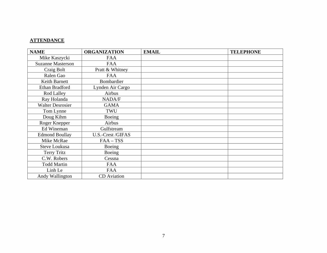
ATTENDANCE NAME ORGANIZATION EMAIL TELEPHONE
Mike Kaszycki FAA Suzanne Masterson FAA
Craig Bolt Pratt & Whitney Ralen Gao FAA
Keith Barnett Bombardier Ethan Bradford Lynden Air Cargo
Rod Lalley Airbus Ray Holanda NADA/F
Walter Desrosier GAMA Tom Lynne TWU Doug Kihm Boeing
Roger Knepper Airbus Ed Wineman Gulfstream
Edmond Boullay U.S.-Crest /GIFAS Mike McRae FAA – TSS
Steve Loukusa Boeing Terry Tritz Boeing
C.W. Robers Cessna Todd Martin FAA
Linh Le FAA Andy Wallington CD Aviation

Presented to:
By:
Date:
Federal AviationAdministrationApril 2010
FAA Status UpdateTransport Airplane and Engine Issues Group
TAEIG
Mike Kaszycki, Manager, Transport Standards Staff
April 14, 2010
2 2Federal AviationAdministration
FAA Status UpdateApril 14, 2010
April 2010 TAEIG Meeting
Topics:
• Rulemaking project status• Non-rulemaking project status• Rulemaking harmonization

3Federal AviationAdministration
FAA Status UpdateApril 14, 2010
April 2010 TAEIG Meeting
Rulemaking Project Status (since Sept 2009)
• Part 25/26 related Final Rules– None
• Part 25/26 Notices of Proposed Rulemaking– None

4Federal AviationAdministration
FAA Status UpdateApril 14, 2010
April 2010 TAEIG Meeting
Rulemaking Project Status (since Sept 2009)
• Part 33/35 related Final Rules– Engine Overtorque Test (§ 33.84)
• Issued August 24, 2009
• Part 33/35 Notices of Proposed Rule Making– None

5Federal AviationAdministration
FAA Status UpdateApril 14, 2010
April 2010 TAEIG MeetingRulemaking Project Status (since Sept 2009)
Final Rules• FRs in OMB/OST:
– 1 part 25 project• FRs in Headquarters (HQ) for coordination:
– 1 part 25 project• FRs in directorate coordination:
– None• FRs in development:
– 1 part 25 project– 1 part 121 project related to part 25

6Federal AviationAdministration
FAA Status UpdateApril 14, 2010
April 2010 TAEIG MeetingRulemaking Project Status (since Sept 2009)
Notices of Proposed Rulemaking• NPRMs open for comment
– none• NPRMs in OST/OMB:
– 1 part 25 project• NPRMs in HQ for coordination:
– 1 part 25 project– 1 part 33 project
• NPRMs in ARAC WG Phase 4 Review:– None
• NPRMs in Directorate for coordination:– none

7Federal AviationAdministration
FAA Status UpdateApril 14, 2010
April 2010 TAEIG Meeting
Rulemaking Project Status (since Sept 2009)
New Tasking• Part 25 Fuel System Lightning Protection
– ARC chartered (August 20, 2009)• Part 25 Low Speed Awareness & Alerting
– ARAC comments on tasking notice received– Tasking publication expected in mid 2010
• Airworthiness Directives Implementation– ARC Chartered (August 20, 2009)

8Federal AviationAdministration
FAA Status UpdateApril 14, 2010
April 2010 TAEIG Meeting
Non-Rulemaking Project Status (since Sept 2009)
• Part 25 Final Advisory Circulars (AC) issued:– AC 25.1419-2, Compliance with the Ice Protection Requirements of
§§ 25.1419(e), (f), (g), and (h). Issued October 27, 2009• Part 25 Draft ACs issued:
– AC 25-27X, Development of Transport Category Airplane Electrical Wiring Interconnection Systems Instructions For Continued Airworthiness Using An Enhanced Zonal Analysis Procedure
• Public comment closed: December 4, 2009• Part 121 Draft ACs issued (related to part 25):
– AC 121.321-X, Compliance With Requirements Of § 121.321, Operations In Icing
• Public comment closed: April 5, 2010

9Federal AviationAdministration
FAA Status UpdateApril 14, 2010
April 2010 TAEIG Meeting
Non-Rulemaking Project Status (since Sept 2009)
• Part 25/26 Final Policy issued:– Interaction of Interior Structures, Including Seats. Issued January 28,
2010– Notice to Rescind Policy Statement PS-ANM100-2002-00102,
"Requirement for Flight Flutter Tests to Determine Freedom from Shock Induced Flutter Phenomena." Issued November 8, 2009
• Part 25 Draft Policy issued:– Policy Statement on Engine Rotor Lock
• Public comment closed February 26, 2010

10Federal AviationAdministration
FAA Status UpdateApril 14, 2010
April 2010 TAEIG Meeting
Non-Rulemaking Project Status (since Sept 2009)
• Part 33 Final Advisory Circulars (AC) issued:– Guidance for 30-Second and 2-Minute One-Engine-Inoperative
(OEI) Ratings for Rotorcraft Turbine Engines (33.7)• Issued June 11, 2009
– Guidance Material for Aircraft Engine Life-Limited Parts Requirements (33.70)
• Issued July 31, 2009

11Federal AviationAdministration
FAA Status UpdateApril 14, 2010
April 2010 TAEIG MeetingNon-Rulemaking Project Status (since Sept 2009)
• Part 33 Final Advisory Circulars (AC) issued:– Bird Ingestion Certification Standards (§ 33.76). Issued 8/7/09.– Damage Tolerance of Hole Features in High-Energy Turbine
rotors (§ 33.70) Issued 8/28/09.– Comparative Methods to Show Equivalent Vibratory Stresses
and High Cycle Fatigue Capability for Parts Manufacturer Approval of Turbine Engine and Auxiliary Power Unit Parts [Old vibration AC] (§ 33.83) Issued 9/8/09.
– Extended Operations (ETOPS) Eligibility For Turbine Engines (§ 33.201) Issued 1/21/10.

12Federal AviationAdministration
FAA Status UpdateApril 14, 2010
April 2010 TAEIG Meeting
Non-Rulemaking Project Status (since Sept 2009)
• Part 33 Final Policy issued – Use of Structural Dynamic Analysis Methods for Blade
Containment and Rotor Unbalance Tests on Derivative Engines (33.94)
• Issued April 20, 2009.– Policy for Continued Airworthiness Assessment Methodology
for Rotating Turbine Engine-Life-Limited Parts Life Shortfall (33.70)
• Issued October 27, 2009.– Approval Method (PMA or STC) for Bolt-On Replacement Parts
for Reciprocating Engines (Part 33) • Issued December 21, 2009.
13Federal AviationAdministration
FAA Status UpdateApril 14, 2010
April 2010 TAEIG Meeting
Non-Rulemaking Project Status (since Sept 2009)
• Part 33 Draft ACs:– Guidance for Pressurized Engine Static Parts (33.64);
• Public comment closed: 11/6/09.– Ratings and Operating Limitations for Turbine Engines (33.7);
• Public comment closed: 2/26/10.– Engine Component Tests (33.91);
• Public comment closed: 4/5/10.
14Federal AviationAdministration
FAA Status UpdateApril 14, 2010
April 2010 TAEIG Meeting
Non-Rulemaking Project Status (since Sept 2009)
• Part 33 Draft Policy – Engine Reliability in Extended Operations (ETOPS)
– Continued Operational Safety (COS) Assessment; • Public comment closed: 11/18/09.
– Aviation Fuel and Oil Operating Limitations, § 33.7; • Public comment due: 4/16/10.

15 15Federal AviationAdministration
FAA Status UpdateApril 14, 2010
April 2010 TAEIG Meeting
• Rulemaking Harmonization– Flightcrew Alerting (25.1322)
• Final rule in work
– NPRMs in work to envelop • CS 25.1302• Certain airplane performance standards• Pilot compartment view and landing gear mechanism
standards
– Additional rulemaking planned over the next 4 years for backlog of enveloping harmonization rules

16 16Federal AviationAdministration
FAA Status UpdateApril 14, 2010
April 2010 TAEIG Meeting
• Rulemaking Harmonization (con’td)– FAA / EASA / TCCA Rulemaking Cooperation
• Last meeting in February 2010 in Cologne (only FAA / EASA)• Review status of 7 test cases• Revised working method definitions to fit 3+ agencies• Reviewed FAA and EASA inventories for airworthiness,
operations, and maintenance rulemaking projects• Working methods and technical POCs provided for all
potential projects in all three areas for 4 year plans• Potential schedule changes to improve alignment of activities
were noted for continued review
17 17Federal AviationAdministration
FAA Status UpdateApril 14, 2010
April 2010 TAEIG Meeting
• Rulemaking Harmonization (con’td)– Certification, Maintenance, and Rulemaking Team
• The next CMR Team meeting is April 27-29 in Cologne• CMR will review the Rulemaking Cooperation effort and
status of the 7 test cases• Proposal for common rulemaking inventory
ASAWG Final Report
TAEIG 14 Apr 10
Table of Content
Reminder: ARAC Specific Risk Tasking
Task#4 Executive Summary
Task#4 Report Common Format Template
Task#4 Final Recommendations: - Aging & Wear - MMEL - Flight & Diversion Time - Latent Failures
Conclusion

ARAC Specific Risk Tasking Statement of Issue
• Previous ARAC harmonization working groups, and regulatory agencies, produced varying recommendations to handle specific risk
• Aircraft are becoming increasingly integrated where individual system functional boundaries may not be well defined
• Inconsistencies in the safety analysis across systems could result in the use of non- standardized system safety assessments across various critical systems making it hard to properly evaluate at the aircraft level

ARAC Specific Risk Tasking• FAA Notice on 3/21/06 - ARAC Tasking to
TAEIG– Task#1 - Develop definition(s) and examples– Task#2 - Review of existing material and identify
industry application– Task#3 - Determine adequacy of existing and
proposed regulatory and guidance material– Task#4 - Develop recommendations for
rulemaking and guidance material

ARAC Specific Risk Tasking• ASAWG Formulation on 7/25/06 – TAEIG Tasking
to ASAWG – Co-Chairs
• Roger Knepper – Airbus• Ed Wineman - Gulfstream
– 18 Total members• 7 Airframers• 5 Suppliers• 4 Regulatory• 2 Users
– Over 32 SMEs identified with half currently active in covering both operations and design

The change recommendations are a more consistent approach acrosssystems that if implemented would:
• Assure a warranted level of specific risk regulation, i.e. inconsistency potentially results in over- or under-regulation, and
• Avoid undue burden on the applicant and regulatory authorities.
Task#4 (Executive Summary)The ASAWG concluded on change recommendations for
• Aging & Wear• MMEL• Flight & Diversion Time• Latent Failures
Change recommendations for Aging & Wear, MMEL, Flight & Diversion Time:• Are built on the latest SDAHWG’s Arsenal version of AC25.1309 and AMC
25.1309• MMEL also includes a recommendations to Industry and the Authorities
(FAA Flight Standards, EASA, TCCA, etc.) for potential incorporation into MMEL Development Process

Task#4 (Executive Summary)Change recommendations for Latent failures are related to:
• FAR/CS 25.1309(b), 25.629, 25.671, 25.901, 25.933, and 25.981• and SDAHWG’s Arsenal version of AC25.1309 and AMC 25.1309 and to the
latest (draft) AC/AMC 25.629, 25.671, 25.901, and 25.933
Note: The ASAWG did not have the expertise to recommend changes to AC/AMC 25.981(a)(1) & (2), but recognize the need to update these to at least result in more realistic consideration of the conditional probability that the presence of a potential ignition source will result in a catastrophic fuel tank explosion.
CAVEAT: The benefits of implementing the proposed changes would be invalidated without the complete implementation of all the changes in total by theAuthorities (FAA, EASA, TCCA, etc.).

Task#4 Report Common Format Template
I. Executive Summary
II. Benefits of the Recommended Changes
III. Applicability of the Recommended Rules/ACs
IV. The Recommendations
V. General Comments on Costs and Benefits (beyond Section II above) of the Recommendations.
VI. Alternatives Considered
VII. Dissenting Opinions

Task#4 Final Recommendations
- Aging & Wear - MMEL - Flight & Diversion Time - Latent Failures

Aging & Wear
Task#4 Final Recommendations

Aging & WearFinal recommendation:• Clarifies appendix 3, b (1) of AC 25.1309 (Arsenal) / AMC 25.1309 for the
consideration of system component aging & wear aspects.• Note: Although it is recognized that a revision of 25.1529, AC/AMC 25.19
and App. H 25.4 is out of the scope of the ASAWG ARAC tasking, the recommended changes provided in this section may require revision of 25.1529, AC/AMC 25.19 and App. H 25.4.
Benefits:• The proposed change increases safety by providing applicants and
regulators clear guidance that can be applied consistently across systems to ensure consistent documentation of system component replacement times that are necessary to protect against aging and wear out.
Applicability:• These changes will apply to new TC or STC and will not be applied
retroactively.
Dissenting opinions:• None

MMEL
Task#4 Final Recommendations

MMELFinal recommendation:• Proposes an uniform approach for assessing quantitatively specific risk
under MMEL dispatch for potential incorporation by Industry and the Authorities (FAA Flight Standards, EASA, TCCA, etc.) into MMEL Development Process,
• Clarifies that reliability analyses concerning MMEL dispatches need not be included in the numerical analyses submitted for certification to show compliance with FAR/CS 25.1309(b) by recommending changes to the Arsenal version of AC 25.1309 and AMC 25.1309, paragraphs 12.b.(1) and paragraph 12.d., and the current AC 25.1309 -1A, paragraph 12.d.
Benefits:• When used to support a proposed MMEL item’s qualitative assessment, the
recommended numerical analysis guidance would provide a standardized methodology that would maintain fleet average reliability objectives.
Applicability:• These changes will apply to new TC or STC and is not intended to be
applied retroactively, unless requested by the applicant.
Dissenting opinions:• None
Flight & Diversion Time
Task#4 Final Recommendations
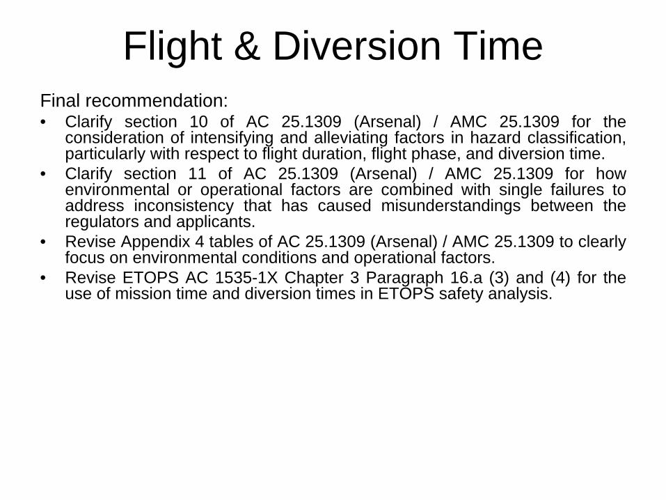
Flight & Diversion TimeFinal recommendation:• Clarify section 10 of AC 25.1309 (Arsenal) / AMC 25.1309 for the
consideration of intensifying and alleviating factors in hazard classification, particularly with respect to flight duration, flight phase, and diversion time.
• Clarify section 11 of AC 25.1309 (Arsenal) / AMC 25.1309 for how environmental or operational factors are combined with single failures to address inconsistency that has caused misunderstandings between the regulators and applicants.
• Revise Appendix 4 tables of AC 25.1309 (Arsenal) / AMC 25.1309 to clearly focus on environmental conditions and operational factors.
• Revise ETOPS AC 1535-1X Chapter 3 Paragraph 16.a (3) and (4) for the use of mission time and diversion times in ETOPS safety analysis.
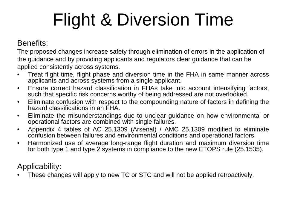
Flight & Diversion TimeBenefits:The proposed changes increase safety through elimination of errors in the application ofthe guidance and by providing applicants and regulators clear guidance that can beapplied consistently across systems.• Treat flight time, flight phase and diversion time in the FHA in same manner across
applicants and across systems from a single applicant.• Ensure correct hazard classification in FHAs take into account intensifying factors,
such that specific risk concerns worthy of being addressed are not overlooked.• Eliminate confusion with respect to the compounding nature of factors in defining the
hazard classifications in an FHA.• Eliminate the misunderstandings due to unclear guidance on how environmental or
operational factors are combined with single failures.• Appendix 4 tables of AC 25.1309 (Arsenal) / AMC 25.1309 modified to eliminate
confusion between failures and environmental conditions and operational factors.• Harmonized use of average long-range flight duration and maximum diversion time
for both type 1 and type 2 systems in compliance to the new ETOPS rule (25.1535).
Applicability:• These changes will apply to new TC or STC and will not be applied retroactively.
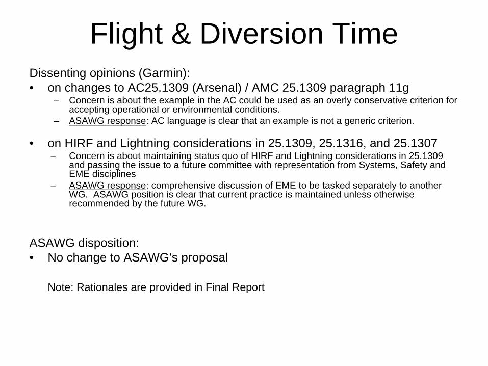
Flight & Diversion TimeDissenting opinions (Garmin):• on changes to AC25.1309 (Arsenal) / AMC 25.1309 paragraph 11g
– Concern is about the example in the AC could be used as an overly conservative criterion for accepting operational or environmental conditions.
– ASAWG response: AC language is clear that an example is not a generic criterion.
• on HIRF and Lightning considerations in 25.1309, 25.1316, and 25.1307
Concern is about maintaining status quo of HIRF and Lightning considerations in 25.1309 and passing the issue to a future committee with representation from Systems, Safety and EME disciplines
ASAWG response: comprehensive discussion of EME to be tasked separately to another WG. ASAWG position is clear that current practice is maintained unless otherwise recommended by the future WG.
ASAWG disposition:• No change to ASAWG’s proposal
Note: Rationales are provided in Final Report

Latent Failures
Task#4 Final Recommendations
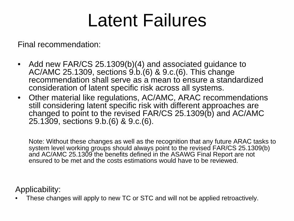
Latent FailuresFinal recommendation:
• Add new FAR/CS 25.1309(b)(4) and associated guidance to AC/AMC 25.1309, sections 9.b.(6) & 9.c.(6). This change recommendation shall serve as a mean to ensure a standardized consideration of latent specific risk across all systems.
• Other material like regulations, AC/AMC, ARAC recommendations still considering latent specific risk with different approaches are changed to point to the revised FAR/CS 25.1309(b) and AC/AMC 25.1309, sections 9.b.(6) & 9.c.(6).
Note: Without these changes as well as the recognition that any future ARAC tasks to system level working groups should always point to the revised FAR/CS 25.1309(b) and AC/AMC 25.1309 the benefits defined in the ASAWG Final Report are not ensured to be met and the costs estimations would have to be reviewed.
Applicability:• These changes will apply to new TC or STC and will not be applied retroactively.

Latent FailuresBenefits:
The key benefit is harmonization and consistency across all systems and between various regulation bodies. ASAWG was not tasked to respond to a specific event or threat that had occurred. Therefore potential measurable safety benefits were not identified.
The proposed changes:• Eliminates the inconsistent application of various residual risk criteria via IPs and CRIs
ranging from 1E-3 to 1E-6. Manufacturers and Regulators alike spend excessive time early in the airplane development cycle negotiating these based on their specific airplane and system designs
• Increases safety by providing applicants and regulators clear guidance that can be applied consistently across systems
• Avoids non-standardized system safety assessments across various critical systems making it hard to properly evaluate at the aircraft level, which could cause conflicting interpretations for conducting system safety assessments in aircraft certification programs
• Provides for an acceptable level of safety across all systems and applications. This is intended to be adequate for coverage of all systems related to specific risk and minimize the generation of new rules, special conditions, IPs, CRIs, etc. in the future
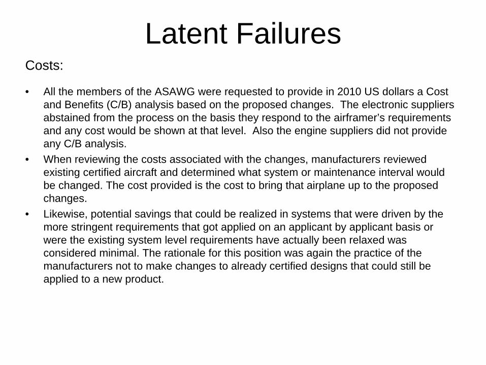
Latent FailuresCosts:
• All the members of the ASAWG were requested to provide in 2010 US dollars a Cost and Benefits (C/B) analysis based on the proposed changes. The electronic suppliers abstained from the process on the basis they respond to the airframer’s requirements and any cost would be shown at that level. Also the engine suppliers did not provide any C/B analysis.
• When reviewing the costs associated with the changes, manufacturers reviewed existing certified aircraft and determined what system or maintenance interval would be changed. The cost provided is the cost to bring that airplane up to the proposed changes.
• Likewise, potential savings that could be realized in systems that were driven by the more stringent requirements that got applied on an applicant by applicant basis or were the existing system level requirements have actually been relaxed was considered minimal. The rationale for this position was again the practice of the manufacturers not to make changes to already certified designs that could still be applied to a new product.
Latent FailuresCosts:
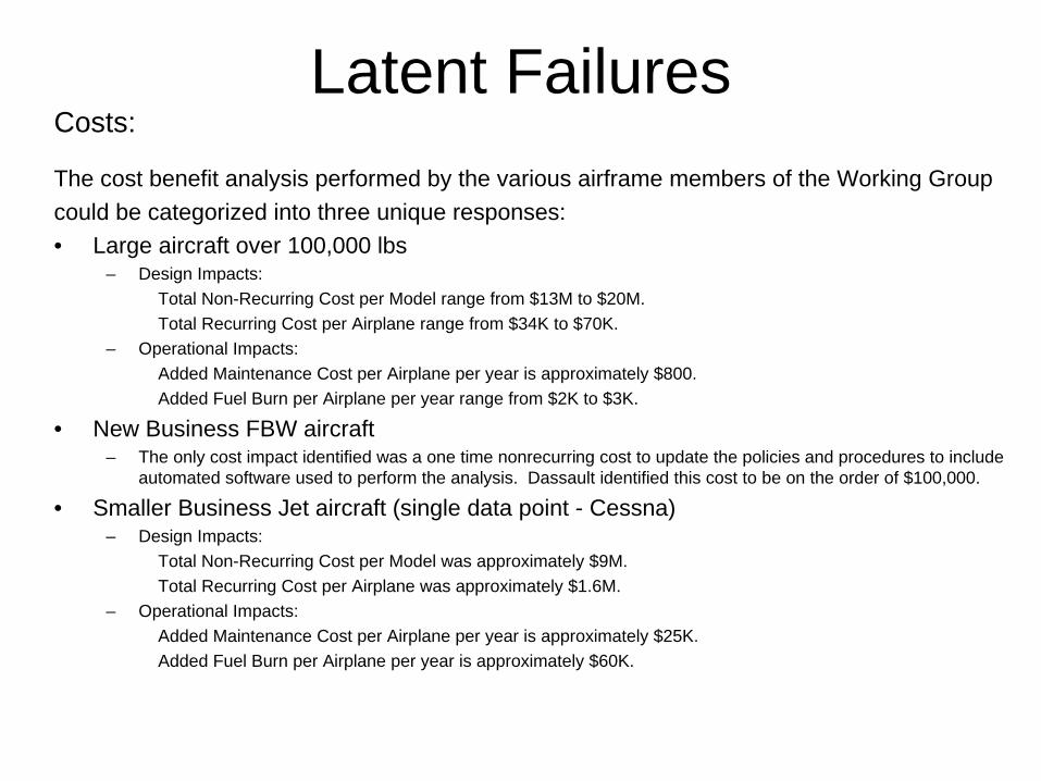
The cost benefit analysis performed by the various airframe members of the Working Group could be categorized into three unique responses:• Large aircraft over 100,000 lbs
– Design Impacts:Total Non-Recurring Cost per Model range from $13M to $20M.Total Recurring Cost per Airplane range from $34K to $70K.
– Operational Impacts:Added Maintenance Cost per Airplane per year is approximately $800.Added Fuel Burn per Airplane per year range from $2K to $3K.
• New Business FBW aircraft– The only cost impact identified was a one time nonrecurring cost to update the policies and procedures to include
automated software used to perform the analysis. Dassault identified this cost to be on the order of $100,000.
• Smaller Business Jet aircraft (single data point - Cessna)– Design Impacts:
Total Non-Recurring Cost per Model was approximately $9M.Total Recurring Cost per Airplane was approximately $1.6M.
– Operational Impacts:Added Maintenance Cost per Airplane per year is approximately $25K.Added Fuel Burn per Airplane per year is approximately $60K.
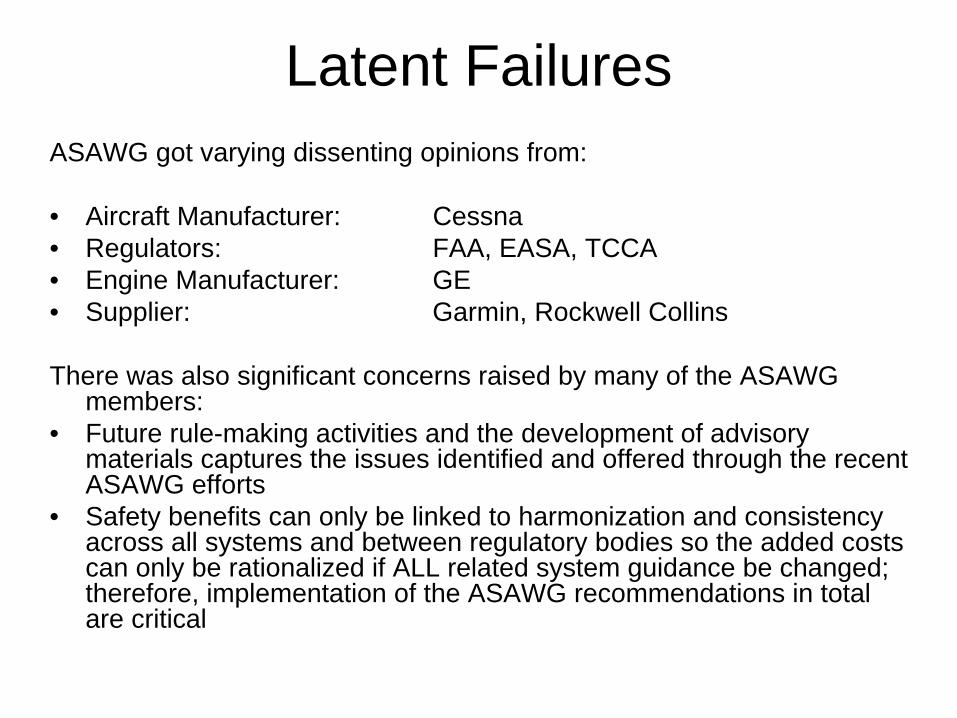
Latent FailuresASAWG got varying dissenting opinions from:
• Aircraft Manufacturer: Cessna• Regulators: FAA, EASA, TCCA• Engine Manufacturer: GE• Supplier: Garmin, Rockwell Collins
There was also significant concerns raised by many of the ASAWG members:
• Future rule-making activities and the development of advisory materials captures the issues identified and offered through the recent ASAWG efforts
• Safety benefits can only be linked to harmonization and consistency across all systems and between regulatory bodies so the added costs can only be rationalized if ALL related system guidance be changed; therefore, implementation of the ASAWG recommendations in total are critical

Latent FailuresDissenting opinions (Cessna):• on changes to FAR/CS 25.1309 and AC25.1309 (Arsenal) / AMC 25.1309
– Concern is about not demonstrating that the change results in a net safety increase or that it can be supported by a cost benefits analysis
Dissenting opinions (EASA):• on changes to 25.933(a)(1)(ii) and associated advisory material
– Concern is about that the change could be seen as a reduction of safety compared to what is currently achieved by compliance with CS 25.933(a)(1)(ii). This is mainly driven by the fact that the proposed 25.1309(b)(4) only addresses the combination of two failures, either of which could be latent
Dissenting opinions (FAA):• on changes to FAR/CS 25.1309 and AC25.1309 (Arsenal) / AMC 25.1309
– Concern is about the term “on the order of” directly being in the rule– Concern is about not having a rule requiring elimination or minimization of significant latent
failures unless impractical• on changes to AC 25.629-1A Section 5.c.(3)(c)
– Concern is about inappropriate consideration of certain combinations of failures, such as dual electric or dual hydraulic system failures, or any single failure in combination with certain electric or hydraulic system failures,
• on changes to FAR/CS 25.671(c)(3) and TAEIG draft AC/AMC 25.671– Concern is about not specifically addressing jams. – Note: there was no FAA dissent on (c)(2) which deals with failures other than jams.
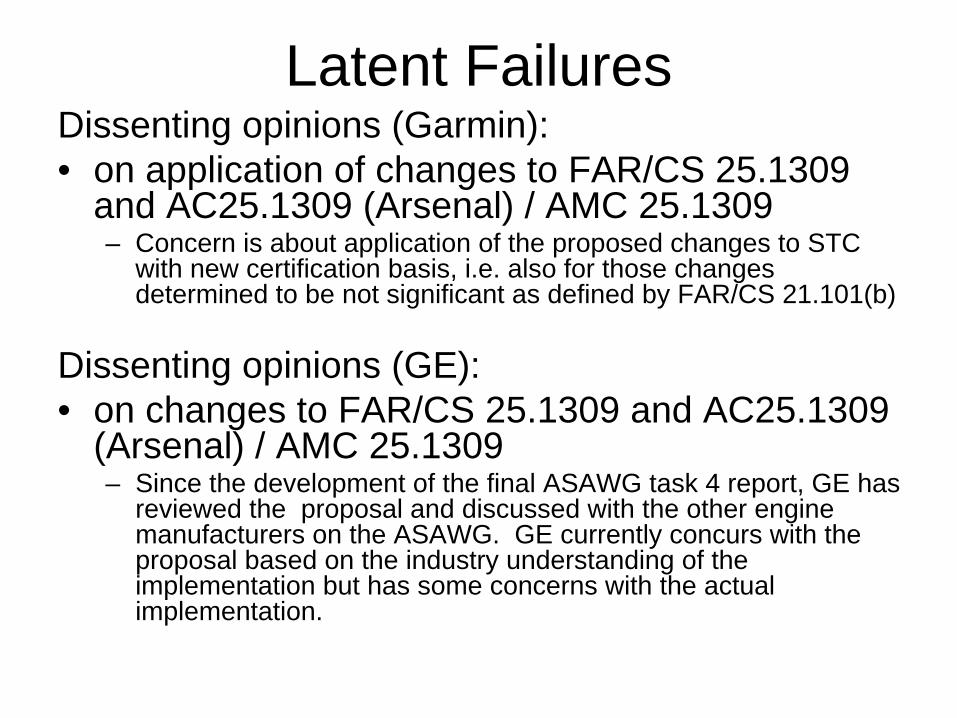
Latent FailuresDissenting opinions (Garmin):• on application of changes to FAR/CS 25.1309
and AC25.1309 (Arsenal) / AMC 25.1309– Concern is about application of the proposed changes to STC
with new certification basis, i.e. also for those changes determined to be not significant as defined by FAR/CS 21.101(b)
Dissenting opinions (GE):• on changes to FAR/CS 25.1309 and AC25.1309
(Arsenal) / AMC 25.1309– Since the development of the final ASAWG task 4 report, GE has
reviewed the proposal and discussed with the other engine manufacturers on the ASAWG. GE currently concurs with the proposal based on the industry understanding of the implementation but has some concerns with the actual implementation.

Latent FailuresDissenting opinions (Rockwell Collins):• Concern is about that modifications to the current regulations and associated certification process
for avionics systems are unnecessary without a demonstrated industry "safety need" based on in- service accident or incident data. However should the industry produce this documented need, then Rockwell Collins believes that the Latent Task Recommendations are reasonable from a technical point of view.
Dissenting opinions (TCCA):• on changes to FAR/CS 25.1309 and AC25.1309 (Arsenal) / AMC 25.1309
– Concern is about the term “on the order of” directly being in the rule without further definition or boundaries
– Concern is about the new AC/AMC section 9. (b)(6) related to latent failures with guidance identifying the intent that they be eliminated wherever practical. The need for further enforcement like “Where means of avoiding significant latent failures that can contribute to catastrophic failure conditions is considered or has been shown to be practical (e.g. thrust reverser systems), such means shall be applied” is seen as necessary.
– Concern is about the new FAR/CS 25.1309(b)(4)(ii) not taking into account any latent failure in combination with an operational or environmental condition

Latent FailuresASAWG Response: • Although the dissents have many facets, the “forerunner” concerns center
around the following:– Enforcement issue regarding elimination/minimization of significant latent failures when
practical to do so, potentially resulting in over-relaxation of current safety level for TR. This was commonly expressed by EASA, FAA, and TCCA.
– The inclusion of “on the order of” in the rule itself could generate compliance issues. This was expressed by FAA and TCCA
– Cost of change does not result in measurable net increase in safety. Expressed by Cessna
ASAWG disposition: • ASAWG determines that the dissents do not invalidate their basic
recommendations. The recommendations achieve the tasking objective of harmonizing specific risk criteria across all systems in a way that is practical without sacrificing safety.
• ASAWG opted not to make changes to the recommendations in response to the various dissenting opinions.
Note: Rationales are provided in Final Report

Conclusion• ASAWG concluded on change recommendations for Aging & Wear,
MMEL, Flight & Diversion Time, Latent Failures
• Flight & Diversion Time and Latent Failures:– ASAWG provided recommendations to TAEIG regarding
dissenting opinions
• ASAWG provided benefits and cost impacts for Latent Failure change recommendation
• ASAWG recommends the complete implementation of all the changes in total by the Authorities (FAA, EASA, TCCA, etc.) otherwise the benefits of the proposed changes would be invalidated
• ASAWG is asking for TAEIG’s approval of the Final Report and transmittal to the FAA


ARAC ASAWG Report
Specific Risk Tasking
(Rev. 5.0)
April 2010
Ed Wineman ASAWG Co-chair
Roger Knepper ASAWG Co-chair

Specific Risk___________________________________________________________1
ARAC ASAWG Report April 2010 Rev 5.0
REVISION SHEET
Rev Description Summary Date
1.0 Basic Release Nov 2006
2.5 Updated with comments included up to Web Meeting #5 May 2007
Comments provided up to Meeting #4 (Merignac)
- Included Fig 6-1 (Design risk).
- “Increase” wording was excluded from SR definition.
- SRC (Specific Risk of Concern) definition was introduced along with the revision of Fig 6-2 (Task 3 entry flow diagram).
- It was identified additional conditions for further considerations (Operating Mode, Flight Condition, Flight Phase, and At Risk Time), based on the review of SR definition.
Jun 2007
Addressed Rev 2.7 comments provided by: Rod L., Alain C, Christophe G, Roger K, David M, Jim M, Linh L, Mike M, Nelson W, Ramesh N and Jim M.
Jul 2007
2.7
Incorporate comments discussed during WM6, WM7 and WM8.
Aug 2007
3.0X Version of the report reviewed by members for closure of the Task 1 and Task 2.
Cleaned up version sent out for TAEIG review
Oct 2007
3.0 Task 3 report version (Seattle Meeting) Apr 2008
4.0 Task 4 report version Sep 2009
5.0 Final report version Apr 2010

Specific Risk___________________________________________________________2
ARAC ASAWG Report April 2010 Rev 5.0
TABLE OF CONTENT
1 EXECUTIVE SUMMARY .................................................................................................................................... 5
2 PURPOSE / BACKGROUND................................................................................................................................ 8
3 SCOPE..................................................................................................................................................................... 9
4 ABBREVIATIONS............................................................................................................................................... 11
5 BIBLIOGRAPHY................................................................................................................................................. 12
6 DEVELOPMENT ................................................................................................................................................. 13
6.1 TASK 1 ................................................................................................................................................................ 13 6.1.1 Introduction .............................................................................................................................................. 13 6.1.2 SR & SRC definitions................................................................................................................................ 13 6.1.3 Application of the Definition .................................................................................................................... 15 6.1.4 SR examples.............................................................................................................................................. 25 6.1.5 ASAWG Recommendation ........................................................................................................................ 29
6.2 TASK 2 ................................................................................................................................................................ 30 6.2.1 Latent Failures Task................................................................................................................................. 31 6.2.2 Active Failures & Design Variability Task............................................................................................... 31 6.2.3 MMEL Task .............................................................................................................................................. 32 6.2.4 Flight & Diversion Time Task .................................................................................................................. 33 6.2.5 Task 2 Table – Excel Workbook ............................................................................................................... 33
6.3 TASK 3 ................................................................................................................................................................ 34 6.3.1 Latent Failures Task................................................................................................................................. 35 6.3.2 Active Failures Task ................................................................................................................................. 39 6.3.3 MMEL Task .............................................................................................................................................. 43 6.3.4 Flight & Diversion Time Task .................................................................................................................. 46
6.4 TASK 4 ................................................................................................................................................................ 51 6.4.1 Latent Failure Task .................................................................................................................................. 51 6.4.2 Aging & Wear Task .................................................................................................................................. 81 6.4.3 MMEL Task .............................................................................................................................................. 84 6.4.4 Flight & Diversion Time Task .................................................................................................................. 91
APPENDIX A ............................................................................................................................................................... 103
6.4.5 Appendix to Latent Failure Task ............................................................................................................ 103 6.4.6 Appendix to Aging & Wear Task ............................................................................................................ 110 6.4.7 Appendix to MMEL Task ........................................................................................................................ 110 6.4.8 Appendix to Flight & Diversion Time Task ............................................................................................ 111
Specific Risk___________________________________________________________3
ARAC ASAWG Report April 2010 Rev 5.0
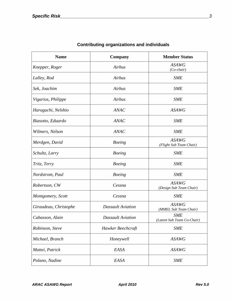
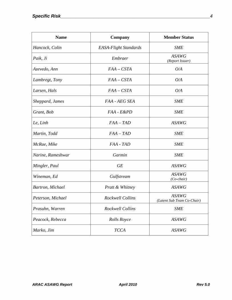
Contributing organizations and individuals
Name Company Member Status
Knepper, Roger Airbus ASAWG (Co-chair)
Lalley, Rod Airbus SME
Sek, Joachim Airbus SME
Vigarios, Philippe Airbus SME
Haraguchi, Nelshio ANAC ASAWG
Biasotto, Eduardo ANAC SME
Wilmers, Nelson ANAC SME
Merdgen, David Boeing ASAWG (Flight Sub Team Chair)
Schultz, Larry Boeing SME
Tritz, Terry Boeing SME
Nordstrom, Paul Boeing SME
Robertson, CW Cessna ASAWG (Design Sub Team Chair)
Montgomery, Scott Cessna SME
Giraudeau, Christophe Dassault Aviation ASAWG (MMEL Sub Team Chair)
Cabasson, Alain Dassault Aviation SME (Latent Sub Team Co-Chair)
Robinson, Steve Hawker Beechcraft SME
Michael, Branch Honeywell ASAWG
Mattei, Patrick EASA ASAWG
Polano, Nadine EASA SME
Specific Risk___________________________________________________________4
ARAC ASAWG Report April 2010 Rev 5.0
Name Company Member Status
Hancock, Colin EASA-Flight Standards SME
Paik, Ji Embraer ASAWG (Report Issuer)
Azevedo, Ann FAA – CSTA O/A
Lambregt, Tony FAA – CSTA O/A
Larsen, Hals FAA – CSTA O/A
Sheppard, James FAA - AEG SEA SME
Grant, Bob FAA - E&PD SME
Le, Linh FAA – TAD ASAWG
Martin, Todd FAA – TAD SME
McRae, Mike FAA - TAD SME
Narine, Rameshwar Garmin SME
Mingler, Paul GE ASAWG
Wineman, Ed Gulfstream ASAWG (Co-chair)
Bartron, Michael Pratt & Whitney ASAWG
Peterson, Michael Rockwell Collins ASAWG (Latent Sub Team Co-Chair)
Prasuhn, Warren Rockwell Collins SME
Peacock, Rebecca Rolls Royce ASAWG
Marko, Jim TCCA ASAWG

Specific Risk___________________________________________________________5
ARAC ASAWG Report April 2010 Rev 5.0
1 Executive Summary
This tasking is to direct the Aviation Rulemaking Advisory Committee (ARAC) to provide information about specific risk assessment and make recommendations for revising requirements or guidance material as appropriate.
An “Airplane-level Safety Analysis Working Group” (ASAWG) was asked to perform the following tasks:
Task 1: Develop definition of specific risk and catalog examples of its application.
Task 2: Identify relevant requirements, guidance and recommendations related to specific risk and its use.
Task 3: Determine adequacy of the existing/proposed standards and if a change is warranted.
Task 4: Develop recommendations for rulemaking and guidance material.
Tasking boundaries are:
Issues outside the flight envelope or outside design specifications are not addressed,
Methodologies not covering airplane certification but currently being employed to handle conditions such as manufacturing defects, quality escapes, etc. (i.e. Gunstone / CAAM) are not addressed,
Specific risks, if they lead to a failure condition of Major or less severe criticality, are not addressed,
Specific risks associated with airframe structures are not addressed.
Task 1 defined Specific Risk in general terms as “The risk on a given flight due to a particular condition”. The Specific Risks of Concern (SRC) are when the airplane is one failure away from a catastrophe, or when the risk is greater than the average probability criteria provided in AC 25.1309 Arsenal for hazardous and catastrophic failure conditions, on a given flight due to a particular condition.
Examples of regulations, guidance and industry practices provided the correct and concise understanding of the specific risk definition.
The particular conditions identified for detailed considerations were:
Latent Failure,

Specific Risk___________________________________________________________6
ARAC ASAWG Report April 2010 Rev 5.0
MMEL,
Active Failure / Design Variability / Flight Condition / Operating Mode,
Flight Time / Diversion Time / Flight Phase / At Risk Time.
The ASAWG reviewed during Task 2 the background and intent of relevant existing requirements, existing guidance material, and ARAC recommendations and explained how specific risk is addressed.
The ASAWG reviewed during Task 3 the results of Tasks 1 & 2 and determined the appropriateness, adequacy, and consistency of the relevant existing regulations, existing guidance material, ARAC recommendations, and industry practices for airplane-level safety analysis. The key approaches to addressing Specific Risk were identified as “fundamental issues”. For each fundamental issue recommendations for Task 4 were developed:
Conducting specific risk evaluations of latent and active failures.
Conducting specific risk evaluation for dispatch under a MEL.
FHA development when dealing with intensifying factors such as flight length, flight phase and diversions.
Documenting component replacement times that are necessary to protect against aging and wear out.
These recommendations demonstrate where a more consistent approach across systems is necessary to:
Assure a warranted level of specific risk regulation, i.e. inconsistency potentially results in over- or under-regulation, and
Avoid undue burden on the applicant and regulatory authorities.
In accordance with the Task 3 outcome, the ASAWG established Task 4 change recommendations for existing regulations, existing guidance material, ARAC recommendations, and industry practices for airplane-level safety analysis. The change recommendations were reviewed with comments and dissenting opinions generated. All dissenting opinions were either reviewed by the entire ASAWG or by the responsible Sub-Group Chair with dispositions developed. These responses were then transmitted back out to the entire ASAWG for one final review.
The ASAWG concluded on change recommendations for Latent failures, Aging & Wear, MMEL and Flight & Diversion Time Task. Along with the change recommendations benefits, applicability, rationales, alternatives considered (if any) and dissenting opinions (if

Specific Risk___________________________________________________________7
ARAC ASAWG Report April 2010 Rev 5.0
any) are provided. These changes will apply to new TC or STC and will not be applied retroactively, unless requested by the applicant.
The change recommendations for Latent failures are related to changing both regulations and guidance material. This is the only change recommendation the ASAWG is recommending to regulations.
ASAWG has made tradeoffs between invalidating existing designs, increasing the analytical burden and being conservative when deriving the recommended airplane level specific risk criteria. The key benefit Industry saw after several years of review and discussion was harmonization and consistency across all systems and between various regulation bodies. Unlike previous working groups that were tasked to respond to a specific event or threat that had occurred, this effort is more of a harmonization across the aircraft and regulatory bodies. Therefore, the identification of potential measurable safety benefits was not identified.
The Latent failure change recommendation:
Eliminates the inconsistent application of various residual risk criteria via IPs and CRIs ranging from 1E-3 to 1E-6. Manufacturers and Regulators alike spend excessive time early in the airplane development cycle negotiating these based on their specific airplane and system designs. The cost related to this was impractical for the manufacturers and regulators to quantify but involve both non-recurring labor cost and recurring equipment costs.
Increases safety by providing applicants and regulators clear guidance that can be applied consistently across systems,
Avoids non-standardized system safety assessments across various critical systems making it hard to properly evaluate at the aircraft level, which could cause conflicting interpretations for conducting system safety assessments in aircraft certification programs. Currently, manufacturers performing aircraft level analysis or highly integrated system level analysis based on the worst case criteria. This has the potential to add cost and complexity to the systems. The actual value of this savings could not be quantified when looking at existing systems.
Provides for an acceptable level of safety across all systems and applications. This is intended to be adequate for coverage of all systems related to specific risk and minimize the generation of new rules, special conditions, IPs, CRIs, etc. in the future.
The change recommendations for Aging & Wear, MMEL Task and Flight & Diversion Time are related to guidance material. Recommendations to change regulations were not seen as appropriate and necessary.
The Ageing & Wear change recommendation increases safety by providing applicants and regulators clear guidance that can be applied across systems to ensure consistent documentation of system component replacement times that are necessary to protect against aging and wear out.

Specific Risk___________________________________________________________8
ARAC ASAWG Report April 2010 Rev 5.0
The MMEL change recommendation provides numerical analysis guidance which would provide a standardized methodology that would maintain fleet average reliability objectives when used to support a proposed MMEL item’s qualitative assessment.
The Flight & Diversion Time change recommendation increases safety through elimination of errors in the application of the guidance and by providing applicants and regulators clear guidance that can be applied consistently across systems:
Treat flight time, flight phase and diversion time in the FHA in same manner across applicants and across systems from a single applicant.
Ensure correct hazard classification in FHAs take into account intensifying factors, such that specific risk concerns worthy of being addressed are not overlooked.
Eliminate confusion with respect to the compounding nature of factors in defining the hazard classifications in an FHA.
Eliminate the misunderstandings due to unclear guidance on how environmental or operational factors are combined with single failures.
Harmonized use of average long-range flight duration and maximum diversion time for both type 1 and type 2 systems in compliance to the new ETOPS rule.
2 Purpose / Background
The FAA established the Aviation Rulemaking Advisory Committee (ARAC) to provide advice and recommendations to the FAA Administrator on the FAA's rulemaking activities for aviation-related issues. Previous ARAC harmonization working groups (Flight Controls, Power Plant Installations, and Systems Design and Analysis) produced varying recommendations regarding the safety of critical airplane systems. Although the subject of specific risk analysis was addressed in those working groups, the recommendations were not consistent. Regulations and Policies developed from within the FAA also provide approaches different from those recommended by ARAC.
If these different approaches are applied on a typical certification project, they could result in non-standardized system safety assessments across various critical systems. This could cause conflicting interpretations for conducting system safety assessments in future aircraft certification programs. After reviewing the existing regulations and the recommendations from the various harmonization-working groups, the FAA Transport Airplane Directorate, along with the European, Canadian, and Brazilian civil aviation authorities, identified a need to clarify and standardize safety assessment criteria. The FAA decided to use a new ARAC tasking to integrate the safety assessment criteria from various system disciplines. In July 2005, an industry group comprised of the Aerospace Industries Association (AIA), General Aviation Manufacturers Association (GAMA), and several aircraft and engine manufacturers, proposed a new tasking. The FAA agreed with the industry group proposal, and has based this tasking on that proposal.

Specific Risk___________________________________________________________9
ARAC ASAWG Report April 2010 Rev 5.0
3 Scope
This tasking is to direct ARAC to provide information about specific risk assessment and make recommendations for revising requirements or guidance material as appropriate. An “Airplane-level Safety Analysis Working Group” (ASAWG) is to perform the following tasks:
Task 1: The ASAWG is to establish a definition for specific risk. It is to provide relevant examples of its application in today’s aircraft certification, FAA Flight Operations Evaluation Board (FOEB), and Maintenance Review Board (MRB) activities.
Task 2: The ASAWG is to review the background and intent of relevant existing requirements, existing guidance material, and ARAC recommendations and explain how specific risk is addressed. In Task 2, the ASAWG is to document all current and proposed approaches to specific risk but should not establish how specific risk should be assessed.
Task 3: The ASAWG is to review the results of Tasks 1 & 2 and determine the appropriateness and adequacy of existing and proposed airworthiness standards for airplane-level safety analysis. This task is to demonstrate if a more consistent approach across systems is necessary. Concurrence from the TAE Issues Group and the FAA is required before continuing to Task 4.
Task 4: The ASAWG is to develop a report containing recommendations for rulemaking or guidance material and explain the rationale and safety benefits for each proposed change. The report is to define a standardized approach for applying specific risk in the appropriate circumstances. The FAA is to define the report format to ensure the report contains the necessary information for developing a Notice of Proposed Rulemaking (NPRM), and/or ACs.
Unlike the tasking statements above, following boundaries were not defined within the tasking, but rather derived by the ARAC ASAWG and agreed by ARAC TAEIG to further bound the tasking. These boundaries are the ARAC Specific Risk tasking should not address issues outside the flight envelope nor outside design specifications. Methodologies currently being employed to handle conditions such as manufacturing defects, quality escapes, etc. (i.e. Gunstone / CAAM) are not covered under Certification of the airplane; therefore, they are also beyond the scope of the ARAC tasking. The ARAC Specific Risk Tasking should not address specific risks, if they lead to a failure condition of Major or less severe criticality.
In addition, specific risk associated with airframe structures should not be addressed by this Tasking. Many of the transport category airplane airworthiness rules, policies and practices used to establish a minimum acceptable level of safety for airframe structure involve regulating what we have defined as a “specific risk”. These rules, policies and practices are often intended to prevent the occurrence of a particular failure (e.g. fracture of a primary structural element) given below average parts (e.g. those with maximum
Specific Risk___________________________________________________________10
ARAC ASAWG Report April 2010 Rev 5.0
undetectable flaws and/or likely damage) are exposed to above average stresses (e.g. limit and/or ultimate loads). However, as indicated by the following statement from Task 3: “This task is to demonstrate if a more consistent approach across systems is necessary”; this overall tasking is focused on “systems” related rules, policies and practices. Consequently, while structural examples may ultimately provide some valuable insights as to how failure prevention might be undertaken for a particular critical part within airplane systems, such examples were not included in Task 2.
Note: This document contains a vast amount of “historical” information generated in the process of reaching the set of recommendations coming out of the tasks. This information is contained in the form of Word tables and Excel workbooks. Due to the size of this information, these files are embedded within the text of this document. Therefore, each of these tables will need to be printed individually if the reader wants a hard copy of this data.

Specific Risk___________________________________________________________11
ARAC ASAWG Report April 2010 Rev 5.0
4 Abbreviations
AC Advisory Circular
AD Airworthiness Directive
AEG Aircraft Evaluation Groups
AFM Aircraft Flight Manual
AIA Aerospace Industries Association
ANAC Agência Nacional de Aviação Civil
ARAC Rulemaking Advisory Committee
ASAWG Airplane-level Safety Analysis Working Group
CAAM Continued Airworthiness Assessment Methodology
CFR Code of Federal Regulations
CMR Certification Maintenance Requirement
CS (JAR) Certification Standard (Joint Aviation Requirements)
CSTA Chief Scientist Technical Advisor
E&PD Engine and Propeller Directorate
EASA European Aviation Safety Agency
EPRD Electronic Part Reliability Data
ETOPS Extended Range Operation
FAA Federal Aviation Administration
FAR Federal Aviation Regulation
FH Flight Hour
FHA Functional Hazard Assessment
FMEA Failure Mode Effect Analysis
FOEB Flight Operations Evaluation Board
GAMA General Aviation Manufacturers Association
HIRF/IEL High Intensity Radio Frequency
IAW In Accordance With
JOEB Joint Operations Evaluation Board
LRU Line Replaceable Unit
MMEL Master Minimum Equipment List
MIL HDBK Military Handbook

Specific Risk___________________________________________________________12
ARAC ASAWG Report April 2010 Rev 5.0
MOC Means of Compliance
MRB Maintenance Review Board
MTBF Mean Time Between Failure
NPRD Non Electronic Part Reliability Data
NPRM Notice of Proposed Rulemaking
OEM Original Equipment Manufacturer’s
PSE Primary Structural Element
SME Subject Matter Expert
SR Specific Risk
SRC Specific Risk of Concern
SSA System Safety Assessment
STC Supplemental Type Certification
TAD Transport Aircraft Directorate
TAEIG Transport Airplane Engine Issues Group
TBD To Be Defined
TCCA Transport Canada Civil Aviation
5 Bibliography
ARP 4761
AC 25.1309
Gunstone
CAAM
Specific Risk___________________________________________________________13
ARAC ASAWG Report April 2010 Rev 5.0
6 Development
6.1 Task 1
6.1.1 Introduction
The ASAWG had to establish during Task 1 a definition for specific risk and provide relevant examples of its application.
Firstly, available specific risk definitions were reviewed and specific risk related regulations, guidance and industry practices were discussed. Then a specific risk and specific risk of concern definitions have been established by the ASAWG. Further on potential relevant conditions for specific risk were identified. These conditions were guided by the ARAC tasking notice. It identifies potential relevant conditions for specific risk as follows: Latent failure, MMEL, Airplane configurations, and Flight conditions.
The specific risk definition was applied to each condition and vice versa with the support of key questions. These questions were crucial for the scope of the ARAC Tasking such as compliance with average probability criteria of 25.1309 Arsenal. This application identified how relevant these conditions were, given the specific risk definition, and whether they would have to be addressed further under ARAC Specific Risk Task 3.
Examples of regulations, guidance and industry practices helped for the correct and concise understanding of the specific risk definition.
6.1.2 SR & SRC definitions
The ARAC Tasking notice required the development of a definition for Specific Risk that considered the certification aspects, operational aspects and maintenance aspects used in today's aircraft design development and certification processes.
The definition for Specific Risk is: “The risk on a given flight due to a particular condition”. The Specific Risks of Concern (SRC) are when the airplane is one failure away from a catastrophe, or when the risk is greater than the average probability criteria provided in AC/AMJ 25.1309 Arsenal for hazardous and catastrophic failure conditions, on a given flight due to a particular condition.

Specific Risk___________________________________________________________14
ARAC ASAWG Report April 2010 Rev 5.0
6.1.2.1 History
In order to develop the definition for specific risk that was thorough yet concise a complete understanding of what went before had to be understood by the ASAWG members.
The genesis of Specific Risk tasking date's back to 1993 with a FAA statement of work to ARAC to develop guidance for specific risk bridging the requirements of 14CFR 25.901(c), 14CFR 25.1309 and MMEL development. The ARAC Working Group (WG) could not close its deliberations by 1998 and recommended guidance in the form of a draft AC (Diamond version of AC/AMJ 25.1309) that supported average risk assessment methodology. In 2001, the FAA proposed revisions to the 1998 ARAC recommendations to cover specific risk. This guidance was introduced into a preliminary Draft AC 25.1309-1BX which lead to draft arsenal version of AC/AMJ 25.1309.
Meanwhile the Diamond version developed in 1998 by the ARAC WG was adopted by the European community and was included with EASA's CS 25.1309 in October of 2003. Also during this time, guidance and policy was being recommended and/or released in the areas of thrust reversers (FAR25.933 and AC 25.933X), fuel tank ignition (SFAR 88, FAR25.981 and AC25.981-1B), powerplant installations (FAR25.901(c) policy), flight controls (FAR25.671) and MMEL policy prohibiting dispatch in catastrophic single-failure conditions.
In the end, it had become apparent that the various approaches were inconsistent when viewed together at the airplane level. In addition, there was no stated common definition or general understanding of "Specific Risk".
6.1.2.2 Rationale
The basic precepts provided to the ASAWG when developing the definition for Specific Risk was it must be thorough yet concise. The definition should not invalidate previous work. The definition should not encompass methodology nor describe how specific risk should be addressed. The goal was to encompass the definition into a single sentence. Finally, the definition had to stand up to a review process that ensured the basic precepts were maintained.
To discuss specific risk at the aircraft level, it was decided to compare it to the quantitative average probability criteria as defined by AC/AMJ 25.1309 Arsenal. The term "Average Risk" is understood to represent the average probability of failure for some baseline population of airplanes over their entire life. Specific risk may be above, below or equal to this average. However, it was recognized that any Specific Risk of Concern must increase the risk relative to the average probability criteria as defined by AC/AMJ 25.1309 Arsenal.
Figure 6-1 illustrates the relationship between the specific risks of concern and the average probability criteria of AC/AMJ 25.1309 arsenal. The Specific Risk of Concern (SRC) depicted represent deviation that can occur on specific flights.
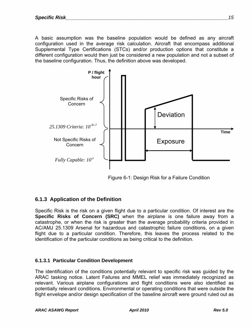
Specific Risk___________________________________________________________15
ARAC ASAWG Report April 2010 Rev 5.0
A basic assumption was the baseline population would be defined as any aircraft configuration used in the average risk calculation. Aircraft that encompass additional Supplemental Type Certifications (STCs) and/or production options that constitute a different configuration would then just be considered a new population and not a subset of the baseline configuration. Thus, the definition above was developed.
Figure 6-1: Design Risk for a Failure Condition
6.1.3 Application of the Definition
Specific Risk is the risk on a given flight due to a particular condition. Of interest are the Specific Risks of Concern (SRC) when the airplane is one failure away from a catastrophe, or when the risk is greater than the average probability criteria provided in AC/AMJ 25.1309 Arsenal for hazardous and catastrophic failure conditions, on a given flight due to a particular condition. Therefore, this leaves the process related to the identification of the particular conditions as being critical to the definition.
6.1.3.1 Particular Condition Development
The identification of the conditions potentially relevant to specific risk was guided by the ARAC tasking notice. Latent Failures and MMEL relief was immediately recognized as relevant. Various airplane configurations and flight conditions were also identified as potentially relevant conditions. Environmental or operating conditions that were outside the flight envelope and/or design specification of the baseline aircraft were ground ruled out as
25.1309 Criteria: 10-9/-7
Fully Capable: 10-z
Exposure
Deviation
Not Specific Risks of Concern
P / flight hour
Time
Specific Risks of Concern

Specific Risk___________________________________________________________16
ARAC ASAWG Report April 2010 Rev 5.0
particular conditions that would be identified and reviewed by the ASAWG for specific risk conditions. Some of these include flight into volcanic ash, flight into icing in excess of the conditions defined in Appendix C of 14CFR25, etc.
Various airplane configurations and flight conditions were further broken down into subsets to include such items as operating modes, active failure conditions, design variability, flight phase, flight time, diversions / return to land conditions and flight conditions. Design variability included design characteristics such as aging and wear that may impact the assumption of a component operating under a random failure distribution condition for the life of the aircraft, but design variability did not include such items as aircraft reconfigurations due to application of an STC to a given aircraft. As stated earlier, an STC aircraft is considered to be a new baseline. Active failure modes were separated from operating modes by recognizing the difference of operating the aircraft under emergency or abnormal operating procedures of the Aircraft Flight Manual (AFM) vs. the normal operating procedures. The distinction between the two is that one mode is entered because of an equipment malfunction while the other is selected by the pilot.
These conditions were then categorized as "Actual" or "Potential". The "Actual Conditions" were defined as those conditions that are identifiable for a specific airplane or flight prior to the initiation of the flight. The "Potential Conditions" were defined as those conditions that are not known to exist for a specific airplane or flight but may be expected to exist prior to the initiation of some flights during the fleet life.
6.1.3.2 Task 3 Relevancy Logic
To determine if a particular condition was a specific risk of concern and was worthy to proceed to Task 3, the ASAWG membership developed a series of decision points to go through. A simple logic diagram is provided in Figure 6-2 that illustrates the decisions that should be passed through to determine if the particular condition is considered Task 3 relevant or not. Only one particular condition at a time goes through the decision points.
The first decision point is simply a determination if the particular condition is considered inside or outside of the design envelope (i.e. design specification) and certification basis of the aircraft. If the condition is outside the design conditions of the aircraft then it is not considered within the boundaries as established for the ARAC Specific Risk tasking.
The remaining decision points in the diagram are an attempt to determine the level of increased risk introduced by each particular condition, with its specific assumptions made for these conditions as identified in 6.1.3.3. This assumption was only applied during Task 1 for the identification of particular conditions to be considered relevant for Task 3.
At this point in the flow diagram, the aircraft configuration does not change from one decision to the next, nor can the particular condition under review be changed. The first decision, determines if the particular condition can leave the aircraft one failure away from a catastrophe. If the answer is no then the next decision point, must be passed for
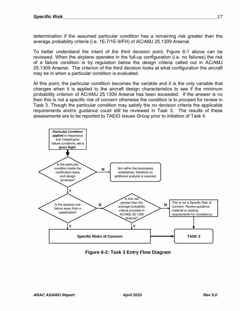
Specific Risk___________________________________________________________17
ARAC ASAWG Report April 2010 Rev 5.0
determination if the assumed particular condition has a remaining risk greater than the average probability criteria (i.e. 1E-7/1E-9/FH) of AC/AMJ 25.1309 Arsenal.
To better understand the intent of the third decision point, Figure 6-1 above can be reviewed. When the airplane operates in the full-up configuration (i.e. no failures) the risk of a failure condition is by regulation below the design criteria called out in AC/AMJ 25.1309 Arsenal. The criterion of the third decision looks at what configuration the aircraft may be in when a particular condition is evaluated.
At this point, the particular condition becomes the variable and it is the only variable that changes when it is applied to the aircraft design characteristics to see if the minimum probability criterion of AC/AMJ 25.1309 Arsenal has been exceeded. If the answer is no then this is not a specific risk of concern otherwise the condition is to proceed for review in Task 3. Though the particular condition may satisfy the no decision criteria the applicable requirements and/or guidance could still be reviewed in Task 3. The results of these assessments are to be reported to TAEIG Issues Group prior to initiation of Task 4.
Figure 6-2: Task 3 Entry Flow Diagram
Is this riskgreater than the
average probability criteria provided in AC/AMJ 25.1309
Arsenal?
Specific Risks of Concern
Not within the boundaries established, therefore no
additional analysis is required.
Is the particular condition inside the certification basis
and design envelope?
Is the airplane one failure away from a
catastrophe?
TASK 3
This is not a Specific Risk of Concern. Review guidance material or existing requirements for consistency.
Particular Condition applied to Hazardous
and Catastrophic failure conditions, on a
given flight.
Y
N
N N
Y
Y

Specific Risk___________________________________________________________18
ARAC ASAWG Report April 2010 Rev 5.0
6.1.3.3 Decision (SRC, non SRC)
To apply the definition for specific risk developed by the ASAWG to a particular condition, the logic diagram described above was used for various conditions that historically had been agreed to be specific risk conditions. These two were latent failures and MMEL dispatch conditions. Additional conditions as defined in 6.1.3.1 were also tested. The following Table 6-1 provides the results of this testing process while the figures provide a graphic step by step view of the logic taken when progressing through the flow chart in Figure 6-2.
Examples from each sub-task are provided using the flow diagram of Figure 6-2 and applying to some particular conditions:
Latent Failure

Specific Risk___________________________________________________________19
ARAC ASAWG Report April 2010 Rev 5.0
MMEL

Specific Risk___________________________________________________________20
ARAC ASAWG Report April 2010 Rev 5.0
Active Failure

Specific Risk___________________________________________________________21
ARAC ASAWG Report April 2010 Rev 5.0
Flight Time
The particular conditions tested and a brief description or examples of the type of conditions were:
Latent Failure – A failure is latent until it is made known to the flight crew or maintenance personnel.
MMEL – Recognized or approved under FAR 91 configurations of the aircraft that are permitted at dispatch using operating rules, but may leave the aircraft in a configuration that is less than that evaluated for certification under FAR/CS 25.
Operating Modes – These are system or aircraft normal modes (abnormal modes are addressed in other particular conditions, e.g. active failures) such as auto pilot on/off, flaps up/down, etc…, that the pilot places the aircraft in.
Flight Condition – This include most of the environmental conditions such as flight over water or high terrain, high altitude operations, operating into high cross winds or extreme cold environments, etc.
Design Variability - Includes design characteristics such as aging, wear, cycle dependencies that may impact the assumption a component was operating under a random failure distribution condition for the life of the aircraft, but it did not include

Specific Risk___________________________________________________________22
ARAC ASAWG Report April 2010 Rev 5.0
such items as aircraft reconfigurations such as application of a specific STC on a given aircraft
Active Failure– Equipment / system failure conditions which are identifiable during the flight for a specific airplane.
Flight Time – Encompasses all the permitted flight that goes into the calculation of average flight time. It recognizes the potential for one aircraft to be operating in a very high cycle condition but low average flight time to the extreme of ultra long flights that include ETOPS operations.
Diversion / Return to Land Conditions – The conditions associated with an in-flight emergency being that requires the crew to proceed to the closest landing site. This could be caused by a medical condition of a passenger or other external event such as a bird strike at takeoff or other.
Flight Phase – Includes the classic conditions such as taxi, takeoff, climb, cruise, descent and landing. Each condition covers the entire average time associated with that condition.
At Risk Time – The period of time at which an item must fail in order to cause the failure effect in question. This is usually associated with the final fault in a fault sequence leading to a specific failure condition.
The particular conditions were categorized as either potential risk conditions or actual risk conditions as defined in section 6.1.3.1 above.
The results of the testing identified ten potential condition categories that the ASAWG had to be investigating during Task 2 and 3. Some examples of these types of conditions and a more thorough explanation of the types of conditions included in these categories are provided in the follow on sections. The conditions identified for further considerations were:
Latent Failure
MMEL
Active Failure
Operating Mode
Flight Condition
Design Variability
Flight Time
Diversion / Return to Land
Flight Phase
At Risk Time

Specific Risk__________________________________________________________________________________________23
ARAC ASAWG Report April 2010 Rev 5.0
The Specific Risk is the risk on a given flight due to a particular condition.
The Specific Risks of Concern (SRC) are when the airplane is one failure away from a catastrophe, or when the risk is greater than the average probability criteria provided in AC/AMJ 25.1309 Arsenal for hazardous and catastrophic failure conditions, on a given flight due to a particular condition.
Particular Condition
applied to Haz / Cat FC on a given flight.
Inside Envelope /
Spec?
Actual or Potential
risk condition?
Is the airplane one failure away
from a catastrophe?
Is the risk greater than the average probability criteria
provided in AC/AMJ 25.1309
Arsenal?
Comments
MMEL Y A N Y
- Acceptable level of safety to be defined (JAR MMEL).
- Standardized approach to be developed.
- Some OEMs satisfy average probability criteria of AC/AMJ 25.1309 Arsenal.
Operating mode
Y A N Y
- Some operating modes inside the envelope are assumed to have a probability of 1 (average probability criteria of AC/AMJ 25.1309 Arsenal not exceeded). There may be other conditions that have probabilities less than 1 (average probability criteria of AC/AMJ 25.1309 Arsenal potentially exceeded, if probability of 1 would be assumed).
- Operating modes related to failures are addressed separately.
- This is not SRC in and of itself.
Flight condition Y A Y Y
- Some flight conditions inside the envelope are assumed to have a probability of 1 (average probability criteria of AC/AMJ 25.1309 Arsenal not exceeded). There may be other conditions that have probabilities less than 1 (average probability criteria of AC/AMJ 25.1309 Arsenal potentially exceeded, if probability of 1 would be assumed). Examples may be crosswind, gust and turbulence.
- Not SRC in and of itself.
Design variability
Y/N A N Y/N - Variability affects a random failure distribution.
Flight phase Y A N Y - Average probability criteria of AC/AMJ 25.1309 Arsenal potentially exceeded, if an occurrence probability especially for this flight phase calculated, i.e. without normalizing using the average flight time hour.
Flight time Y A N Y/N
- If flight time is always below average, than cycling effects are perhaps not properly covered.
- 25.1309 compliance: ETOPS assessments to meet 25.1309 criteria per Part 25 Appendix K. Other SSAs use fleet average flight times which may not be conservative for all cases.
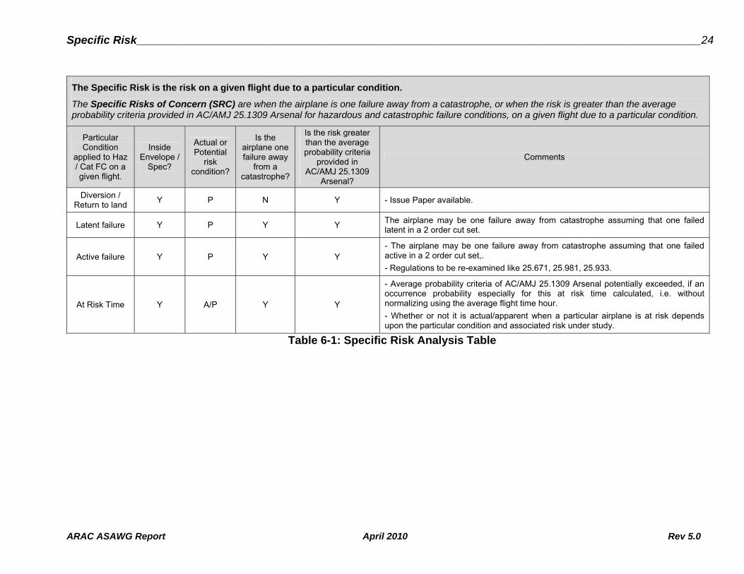
Specific Risk__________________________________________________________________________________________24
ARAC ASAWG Report April 2010 Rev 5.0
The Specific Risk is the risk on a given flight due to a particular condition.
The Specific Risks of Concern (SRC) are when the airplane is one failure away from a catastrophe, or when the risk is greater than the average probability criteria provided in AC/AMJ 25.1309 Arsenal for hazardous and catastrophic failure conditions, on a given flight due to a particular condition.
Particular Condition
applied to Haz / Cat FC on a given flight.
Inside Envelope /
Spec?
Actual or Potential
risk condition?
Is the airplane one failure away
from a catastrophe?
Is the risk greater than the average probability criteria
provided in AC/AMJ 25.1309
Arsenal?
Comments
Diversion / Return to land
Y P N Y - Issue Paper available.
Latent failure Y P Y Y The airplane may be one failure away from catastrophe assuming that one failed latent in a 2 order cut set.
Active failure Y P Y Y - The airplane may be one failure away from catastrophe assuming that one failed active in a 2 order cut set,.
- Regulations to be re-examined like 25.671, 25.981, 25.933.
At Risk Time Y A/P Y Y
- Average probability criteria of AC/AMJ 25.1309 Arsenal potentially exceeded, if an occurrence probability especially for this at risk time calculated, i.e. without normalizing using the average flight time hour.
- Whether or not it is actual/apparent when a particular airplane is at risk depends upon the particular condition and associated risk under study.
Table 6-1: Specific Risk Analysis Table

25
6.1.4 SR examples
6.1.4.1 Latent Failure Task
The Latent Failure Task Group was assigned the task to identify and document the current approaches in order to assess in Task 3 the acceptance criteria for the "significant latent failures” highlighted in paragraph 9.c.6 of the proposed ARAC Advisory Circular (AC) 25.1309 - “Draft ARSENAL version,” dated 6/10/2002.
In order to provide current examples of latent failure applications, the following items were identified. More details like the background, the intent of relevant existing requirements, the existing guidance material, industry practices, and the explanation of how specific risk is addressed should be reviewed and provided in Task 2.
AC 33.28-1 (Engine over-speed criteria)
25.671
ARAC 25.671
Generic IP - 25.933
ARAC 25.933
AC 25-19
AC 25.1309-1A
AC/AMJ 25.1309 - Arsenal
ARP 4761 (Maximum dormancy)
SFAR88 & 25.981
FAA Policy 25.901(c)
IP to 25.901(c)
6.1.4.2 MMEL Task
6.1.4.2.1 Background
The FAA MMEL process is an operational process led in the field by Aircraft Evaluation Groups (AEG). FAA HQ Flight Standards division in Washington, DC controls the policy and overall standardization of the MMEL.
The development of standardization and policy guidance is performed by an MMEL FAA/Industry Group (MMEL IG). The MMEL IG is composed of representatives from the FAA, operators and the industry. This group reviews items of equipment that are required by a new regulatory requirement or are MMEL items that are affected by FAA policy decisions. This process has led to the issuance of a set of FAA Policy Letters in which guidance is given to FOEB chairmen for drafting specific MMELs.

26
FOEB chairmen set up an initial aircraft MMEL based on the aircraft manufacturer’s Proposed MMEL (P-MMEL). During a public FOEB meeting that gathers AEG staff and chairman, the respective aircraft manufacturer [OEM] and operators, the initial MMEL is reviewed, and amended as necessary. This updated MMEL is then posted on FAA Opspecs website [draft section] for public comments. After a specified period of time, public comments are reviewed by the FOEB chairman. Final revisions are then made and the MMEL posted in the "Valid" section of the FAA Opspecs website for public use.
This process is further described in Airworthiness Inspector's Handbook, Order 8300.10 - Volume 2 - Chapter 7. This process is also described in FAA Order 8400.10.
6.1.4.2.2 Developing MMEL
In developing their P-MMEL, manufacturers and operators seeking consideration for relief for operating with certain items of equipment inoperative, are requested to provide supporting documentation that sufficiently substantiates their request. In addition to including an evaluation of the potential outcome of operating with specific items inoperative, this documentation should consider the following topics: the subsequent failure of the next most critical component; the interrelationships between items that are inoperative; the specific conditions under which the equipment is to be allowed to be inoperative [provisos]; any necessary Operations and/or Maintenance procedure [M & O’s]; the proposed repair interval; the impact on approved flight manual procedures; the reliability of critical components; and any/all potential impacts on crew workload that could adversely degrade safety margins.
The basic concept to be applied in accepting an item for inclusion into a Master Minimum Equipment List is that the subsequent failure of the next most critical component in flight must not lead to a catastrophic event. There are other essential considerations too, however such as qualitative requirements that prohibit the incorporation of items of equipment powered by essential buses, or items of equipment necessary to accomplish an emergency procedure[s]. Related to all of these, is guidance for electrical systems on two-engines airplanes. In addition, the MMEL may not conflict with other FAA-approved documents such as the approved aircraft flight manual limitations, emergency procedures, and/or Airworthiness Directives (AD). AD’s always take precedence over any published MMEL relief.
Appropriate restrictions and/or procedures are established to ensure an acceptable level of safety is maintained during the MMEL/MEL deferral period.
Specific OEMs may apply different processes for establishing their Proposed MMEL. These processes range from a full safety analysis established for each item -assigning a probability of one or a conditional probability to the failed item- to a qualitative analysis that is supported by quantitative analysis when requested. These company processes are designed and intended to be more conservative than that required by the FAA.
When an airplane is dispatched under MMEL/MEL relief (i.e. less than full up) it is an example of SRC, as the specific aircraft configuration may now have a risk higher than that established under an average full up configuration.

27
6.1.4.2.3 Non-US Practices
Transport Canada MMEL process is conducted along with Type certification activities, should end at TC date and involves certification specialist. It is based on safety analyses and it mainly looks at the impact of inoperative item coupled with the next failure and assesses whether the residual probability is still “on the order” of what it should be for the failure classification being assessed.
European process is still processed under JAA rules as EASA has not overtaken this activity. It is driven by JAR-MMEL/MEL, specifically by requirement .010(a) which request "to maintain an acceptable level of safety as intended in the applicable JAR or equivalent Requirement".
6.1.4.3 Airplane Configuration Task
The first task of the group, was to identify and discuss how different Operating Modes of Aircraft Systems, Flight Conditions (Environmental Conditions), Active failure and Design Variability where considered in showing compliance.
All the members that provided feedback on their methods of showing compliance used SAE ARP 4761 (published 1996-12), AMC 25.1309 (2006-5), the Arsenal (2002-6) or Diamond Draft (1998-4) of AC 25.1309. There were slight differences between the companies. This can be attributed to relative newness of the system safety process when compared to mature processes (i.e. structures or pressurization).
As outlined in 25.1309 compliance guidelines mentioned above, the applicant in their functional hazard assessments (FHA), evaluate the effect of the functional failure condition on the aircraft and crew based on the worst case within the certification approved standard, flight envelope and design specification. This sets the hazard classification and drives the qualitative and quantitative requirements, as well as requirements for HIRF/IEL, software and hardware design assurance. While this conservatively takes the severity aspect of the specific risk and treats it as the average, there is still the related issue of the conditional probability of being in the “worst case” condition. As credit for these conditional probabilities is increasingly being taken when showing compliance with the probability guidelines (example: AC25-7A, Appendix 7, HQRM), further consideration of these particular conditions in Task 3 was deemed appropriate, not only to assure the overall specific risk is adequately addressed, but also to assure that the probabilities guidelines associated with less severe outcomes are also met.
28
6.1.4.4 Flight & Diversion Time Task
The Flight Length and Diversion Time Task Group was assigned the task to identify and document the current approaches to exposure times where specific risk might be applied.
In order to provide current examples of possible Specific Risk application to flight length and diversion time the following examples were reviewed. More details like the background, the intent of relevant existing requirements, the existing guidance material, and the explanation of how specific risk is addressed had to be reviewed and provided in Task 2.
The first task of the group was to identify and discuss how At Risk Time, Flight Phase, Flight Time and Diversion Time were considered in showing compliance.
“At Risk “ Time
o ARP 4761 Paragraph 2.2 and Appendix D paragraph D.11.1.3.2
o AC/AMJ 25.1309 (Arsenal) Appendix 3 paragraph b2
Flight Phase
o ARP 4761 Appendix A paragraph A.1 and Appendix D paragraph D.11.1.3.2
o AC/AMJ 25.1309 (Arsenal) Appendix 3 paragraph a and paragraph b2
o AC 25.1309-1A
o Draft AC 25.671
o 25.901c exemption B717 docket no. FAA-2003-14201
o Industry examples
Flight Time
o ARP 4761 paragraph 2.2
o AC/AMJ 25.1309 (Arsenal) Appendix 3 paragraph c
o Draft AC 25.671
o Industry examples
Diversion Time
o FAR 121.161
o ETOPS/JAR-OPS
o FAA Part 25 Appendix K (new)
o NPRM Docket No. FAA-2002-6717 Notice No. 03-11
o AC120-42A Extended Range Operation with Two Engine Airplanes
o JAR-OPS 1.246 Extended Range Operation with Two Engine Airplanes
o Return Landing Capability – Generic Issue Paper

29
The group concluded that At Risk Time, Flight Phase, Flight Time, and Diversion Time are examples of specific risk variables and they should be examined further in Tasks 2 and 3.
6.1.5 ASAWG Recommendation
The ASAWG recommends that "Specific Risk" be defined as the “risk on a given flight due to a particular condition”. In addition, the categories of conditions that should be researched further during Task 2 and 3 should be the following:
MMEL
Design Variability
Flight Time
Diversion / Return to Land
Latent Failure
Active Failure
Operating Mode
Flight Condition
Flight Phase
At Risk Time

30
6.2 Task 2
The ASAWG reviewed during Task 2 the background and intent of relevant existing requirements, existing guidance material, and ARAC recommendations and explained how specific risk is addressed. In Task 2, the ASAWG had to document all current and proposed approaches to specific risk but should not establish how specific risk should be assessed. The outcome of this task was a description how specific risk is currently assessed and managed, by currently available regulatory guidance and by actual practice in recent certification programs. Task 2 also included the intended improvements and safety benefits of currently available regulatory guidance and actual practice.
The conditions associated to Specific Risk as recommended according to Task 1 result were categorized as followed:
Latent Failure,
MMEL,
Active Failure / Design Variability / Flight Condition / Operating Mode.
Flight Time / Diversion Time / Flight Phase / At Risk Time.
The task groups working at the above-mentioned categories were guided by the following questions:
What is addressed (regulation or guidance)?
Why is it addressed (regulation or guidance recommendation background / preamble)?
How is it addressed?
o Industry application / practices?
o Acceptability of next most critical failure on safe operation?
o Crew limitations and procedures?
o Reliability of critical components?
o Allowable exposure time?
o Meet average risk criteria of 25.1309?
o One failure away from catastrophe?
The following chapters give the results of Task 2. The results of each task group were detailed in tables addressing the above-mentioned questions.

31
6.2.1 Latent Failures Task
To meet the objectives of Task 2, the ASAWG established a task group to specifically address latent failures and to develop the table below.
The 6.2.1.1 table identifies Part 25 requirements, guidance, and other means that address latent failures, both directly and indirectly. The table also describes how latency is addressed by these criteria. The table identifies examples of application, including both FAA interpretation and industry practice.
In summary, the group found that there were a wide variety of approaches to addressing latency. Certain criteria apply to the latent side, or the active side, of failure combinations, or to the combined failure condition. Criteria also vary depending on whether the latent failure leaves the airplane one failure away from a catastrophic event. Different criteria are applied depending on the type of system being analyzed; for example, flight controls versus power plant installations. There may also be varying criteria for the same system depending on which rule is applied.
6.2.1.1 Latent Failures Task 2 table
Task 2 table.
Note: verify that you are on the “Latent” tab when opening the Task 2 table.
6.2.2 Active Failures & Design Variability Task
To meet the objectives of Task 2, the ASAWG established a task group to specifically address Active Failures, Design Variability, Flight Condition and Operating Mode and to develop the table below.
The table 6.2.2.1 identifies Part 25 and 33 requirements, guidance, and other means that address Active failures, Design Variability, Flight Condition and Operating Mode, both directly and indirectly. The table identifies examples of application, including both FAA interpretation and industry practice.
In summary, the group found that there were a wide variety of approaches to Active Failures. Certain criteria may apply to the active side or the latent side, of failure combinations, or to the combined failure condition.
The task of this group was to consider that the active failure occurred during a given flight. An active failure, which occurred before the flight, is addressed by the MEL or Aircraft Flight Manual.
In addition, the group realized that the airplane can be one failure away from a catastrophe. The group discussed several of these, but the easiest to grasp is the
32
case on a two engine aircraft where one engine has failed. This, by itself, is minor or major, but now the aircraft is one failure away from a catastrophe, another failure that results in the loss of thrust from the other engine to maintain flight.
For design variability, quality escapes, as described in section 3 of this document, are outside the boundary of this document.
6.2.2.1 Active Failures & Design Variability Task 2 table
Task 2 table.
Note: verify that you are on the “Active & Design” tab when opening the Task 2 table.
6.2.3 MMEL Task
To meet the objectives of Task 2, the ASAWG established a Task Group to specifically address specific risk criteria related to the development of a Master Minimum Equipment List (MMEL). Table 6.2.3.1 was generated identifying; the regulations and/or guidance followed in developing an aircraft MMEL; the specific tailoring that an OEM may have utilized during the development of a MMEL; and just how the process addressed the specific risk issues related to the next most critical failure, crew limitations, reliability of critical components, allowable exposure times, quantitative dispatch times and being one failure from a potentially catastrophic condition.
In summary, all the OEMs are following the Flight Operations Evaluation Board (FOEB) process derived from FAA policy letters or a joint FOEB/JOEB process. Though the process that was followed was consistent across the industry, how the MMEL was actually derived and the data used to substantiate the recommended items in the MMEL varied. A common theme, however, did appear in that aircraft systems are becoming more and more functionally integrated using software and complex hardware logic devices to perform critical aircraft functions. Therefore qualitative design assurance processes, human factor aspects and common cause assessments are playing an increasingly important role with respect to MMEL relief.
6.2.3.1 MMEL Task 2 table
Task 2 table.
Note: verify that you are on the “MMEL” tab when opening the Task 2 table.
33
6.2.4 Flight & Diversion Time Task
To meet the objectives of Task 2, the ASAWG established a task group to specifically address Flight Time, Diversion Time, Flight Phase and At Risk Time. The task group documented what the primary issues were regarding the many regulations, guidance materials and industry examples, identified in Task 1.
The 6.2.4.1 table summarizes the associated regulations and background of each, along with industry application and practices. Also several questions were addressed regarding each of these examples. Some of these questions (written with MMEL in mind) are not applicable to flight time and diversion time and are so noted.
In summary, the flight time and diversion time team, notes that the ETOPS rule was recently revised and incorporates text that says it is necessary to meet 25.1309 under the ETOPS allowed configurations, so any changes that are made to 25.1309 is to cover ETOPS by default. Additionally, the item titled "Maximum flight time or maximum diversion time against mean flight time in Functional Hazard Assessments" is to address flight length (which may be driven by ETOPS flight times) assumptions in FHAs. The flight time and diversion time team recommends that all areas be further investigated in Task 3 and be considered within any specific risk discussion. Two items on the table, address basic assumptions made for a system or airplane in its functional hazard assessment with respect to flight length extremes. Assumptions made for shorter or longer than average flight lengths can in some cases result in severity of a failure condition being misclassified.
6.2.4.1 Flight & Diversion Time Task 2 table
Task 2 table.
Note: verify that you are on the “Flight” tab when opening the Task 2 table.
6.2.5 Task 2 Table – Excel Workbook
There are some incomplete fields with missing words in the tables from 6.2.1, 6.2.2, 6.2.3, and 6.2.4 due to the formatting issues, so that an MS Excel workbook is attached as follow:
ASAWG_Task 2 Table
[Click on the above link (icon) for opening the workbook]

34
6.3 Task 3
The ASAWG reviewed during Task 3 the results of Tasks 1 & 2 and determined the appropriateness, adequacy and consistency of the relevant existing regulations, existing guidance material, ARAC recommendations, and industry practices for airplane-level safety analysis. Task 3 demonstrated that a more consistent approach across systems is necessary.
The task groups (latent failure, active failure, MMEL, flight time) were guided by questions designed to help team members assess whether the existing regulations / guidance material / ARAC recommendations / industry practices are:
Adequate?
Appropriate?
Applicable across systems?
The assessment was further guided by the following sub questions
For adequacy:
o Is the reason for the regulation/guidance given (why, preamble)?
o Are all the relevant Hazardous and Catastrophic failure conditions covered?
For appropriateness:
o Is it commensurate with the potential level of risk?
o Is it clear (unique interpretation)?
o Is it a current requirement?
o Is it practicable, i.e. achievable in itself and achievement verifiable?
o Is it redundant with AC 25.1309 Arsenal Version?
o Is it consistent with other rules and guidance related to the particular condition being reviewed?
For applicability
o Is it possible to be applied across all systems for this particular condition?
o Is it possible to be applied across all systems for other particular conditions?
The task groups then identified the “fundamental issues” of the existing regulations / guidance material / ARAC recommendations / industry practices. “Fundamental issues” are the key approaches addressing Specific Risk.

35
For each “fundamental issue”:
The current practice was summarized in Task 2 results.
The pros and cons of the fundamental issues & current practices were identified, and supported by Task 3 questions / answers with regard to adequacy, appropriateness and applicability across systems.
One or more recommendations were provided.
For each fundamental issue recommendations for Task 4 were developed and reviewed by stakeholders (industry & regulators). This review generated comments, the disposition of which is documented in this report.
The following chapters give the results of Task 3. The results of each task group were detailed in tables addressing the above-mentioned questions (adequacy, appropriateness and applicability across systems) and the fundamental issues.
6.3.1 Latent Failures Task
6.3.1.1 Introduction
The latent task group reviewed the various system safety processes for different systems like flight controls, thrust reversers, etc. to determine if specific risk (the risk on an individual flight or flights) is addressed and how. Further consideration was given to whether the methodologies were adequate, appropriate and applied consistently across systems.
From this review, the group identified common concepts / ideas relating to methodologies that addressed specific risk. These were then condensed into fundamental issues. The pro and cons of each fundamental issue were documented and reviewed. From this sub-team review and a subsequent review by stakeholders, general recommendations and additional guidance were identified for Task 4.
6.3.1.2 Task 3 Table
As directed by the tasking, the latent task group determined if the regulations and practices were adequate, appropriate and applicable across systems. The results are documented in the attached Task 3 table. This table was then used to perform the review described in section 6.3.1.3.
ASAWG_Task3 Table_Latent
36
6.3.1.3 Fundamental Issues
The latent task group reviewed current regulations and industry practices to determine common approaches that were used to address Specific Risk Concerns related to latency. After completing this review the task group took a brainstorming approach for allowing each member to voice his / her issues. Once everyone’s issues were collected, they were condensed to the following four fundamental issues.
1 Limit Residual Probability (where “residual” is associated with the remaining risk following an assumed latent failure condition).
2 SRC Latent + 1 (addressing the question “What do you do” when a SRC latent failure condition leaves you one failure away from a catastrophe).
3 Definition of an SRC does not consider probability, leaving applicability too broad for Task 4 (need further criteria for when possible latency is not an SRC so that residual risk is not a concern).
4 Limit Latency.
6.3.1.4 Pros and Cons of Fundamental Issues
The pros and cons of each fundamental issue were discussed and documented in the attached Pros & Cons table. The table addresses each issue at a high level (is it worth implementing), and also focuses on the pros and cons of specific methodologies that incorporate this concept/issue. Based on these pros and cons, the information contained within the recommendation column resulted in the basic recommendations and additional guidance as discussed in 6.3.1.6 and 6.3.1.7, respectively.
ASAWG_ Pros and Cons Table_Latent
6.3.1.5 Stakeholder Review
The general recommendations and additional guidance (sections 6.3.1.6 and 6.3.1.7) were reviewed by stakeholders. This review generated comments, the disposition of which is documented in the attached Stakeholder Review table. Note that some of the stakeholder comments were marked as being applicable for consideration within Task 4 only.
ASAWG_Stakeholder Review_Latent

37
6.3.1.6 Recommendations for Task 4
Based on these pros & cons and recommendations from previous attached tables, general recommendations were made for each fundamental issue as follows:
6.3.1.6.1 First Fundamental Issue – Limit Residual Probability
Establish a single consistent objective criteria and methodologies to limit the worst anticipated residual risk for catastrophic failure conditions.
Determine whether limiting residual probability for any hazardous failure condition is warranted.
6.3.1.6.2 Second Fundamental Issue - SRC Latent + 1
Give special consideration to this issue when addressing residual probability.
6.3.1.6.3 Third Fundamental Issue - Definition of an SRC
Establish screening criteria (or filters) to determine which failure conditions will have additional specific risk criteria applied.
6.3.1.6.4 Fourth Fundamental Issue - Limit Latency
Establish acceptable criteria to limit the exposure to latent failures which are not practical to eliminate.
For example, limit the exposure to a latent failure in an inverse relationship to the failure rate such that maximum total probability of the latent failure is less than some TBD fixed value (e.g., some of the current practices use 1E-3).
We recommend that this issue be carried forward as an and/or consideration with Fundamental Issue 1.
6.3.1.7 Additional Considerations for Task 4
The following additional considerations for Task 4 were derived from a review of the pros and cons associated with each fundamental issue. These additional considerations convey guidance for interpreting the intent of the general recommendations.
1 Limit the application of both residual risk and latency criteria chosen in Task 4 to Catastrophic failure conditions. Limiting residual probability for hazardous failure conditions may not be warranted and will need to be further addressed. [Note: Part 33 Engines worst case failure condition is “Hazardous” by definition of 33.75; there are some concerns with hazardous failure conditions which (a) border on being catastrophic (e.g. 1 in 50) or (b) result in 1 or 2 fatalities].
38
2 Limit the application of both residual risk and latency criteria (e.g., Fundamental Issue 3, see 6.3.1.6.3) chosen in Task 4 by probability and/or cutset order. Only a subset of possible configurations needs to be reviewed and will be determined in Task 4.
3 Establish both the residual risk and latency criteria chosen in Task 4 to set-up a control or acceptable level of risk for the subset population or fleet consistent with the current average risk criteria (e.g., do not drive 1E-9 failure combinations to 1E-12, etc.).
4 Limit the application of both residual risk and latency criteria so that they do not result in excessive analytical workload. Keep the criteria and process as simple as possible.
5 Minimize the architectural impact of both the residual risk and latency criteria chosen in Task 4 by considering the industry standard of reliability range (e.g. MIL-HDBK-217F, TELCORDIA, FIDES, NPRD and EPRD) for components. For example, take a dual failure cutset scenario -- neither the residual risk nor latency criteria should be outside the predicted reliability range of electronic components within that cutset.
6 Limit the application of both the residual risk and latency criteria chosen in Task 4 so that they do not routinely force significant increased model resolution (e.g., the use of LRU level basic events and associated MTBFs should be acceptable in fault tree models if justified by either a FMEA or a common cause analysis). Criteria should account for the existing conservatism in prediction methods like part count or part stress analysis used to calculate MTBFs when applied at the LRU level.
7 Limit the application of both the residual risk and latency criteria and policy chosen in Task 4 so that they do not adversely impact the risk of maintenance errors [e.g., increase the frequency such that traditional shop maintenance is moved to the flight line, increase the frequency of RII tasks (Required Inspection Items), etc.].
8 Establish in a clear, concise manner that both the residual risk and latency criteria chosen in Task 4 will recognize that exposure times are dependent upon when the failure occurs within a specific failure sequence (i.e., exposure times will change based on failure sequence).
9 Establish in Task 4 that “SRC Latent + 1” failure conditions that are catastrophic may be allowed, but should be limited via criteria which are as deterministic and objective as possible. If objective criteria are not attainable, resorting to more subjective case by case engineering judgments may be needed. Deterministic criteria examples are (1) reliance on the one remaining failure that has a failure distribution to some known confidence level, or (2) reliance on the integrity of a single component to those meeting standardized “critical parts” acceptance criteria (examples: special process controls on design, production, operation, and/or maintenance to limit failures of critical parts such as turbine disks or wiring), etc.
39
10 Establish in Task 4 criteria for addressing “SRC Latent +1” failure combinations that are consistent across systems, that do not drive unnecessary redundancy; and that do not drive unnecessary maintenance. Any SRC latent + 1 criteria is not to be defined so broadly that for example 90% of the time the cutset under evaluation could not meet the criteria and thus required additional redundancy.
11 Only allow latency which (a) cannot be eliminated or further reduced through practical means (i.e., like AC 25.1309-1A does now, indicate that relying on maintenance to detect latent failures is undesirable and should not be used in lieu of practical monitoring, etc.), [Note: may need to add more clarifying words in AC 25.1309 to define "practical" (e.g.. bring in technical and economic feasibility, design complexity, maintenance costs, regulatory burden and reliability)] and (b) meets an acceptable total probability criteria (e.g. less than 1E-3).
12 Establish in a clear, concise manner in Task 4 that exposure times equal to the life of the airplane in 3rd order cutsets (or 4th order cutsets, or 5th order cutsets, etc.) will not be prohibited.
6.3.2 Active Failures Task
6.3.2.1 Introduction
The active task group examined the current regulations and guidance material identified in Task 2.
6.3.2.2 Task 3 Table
As directed by the tasking, the sub-team determined if the regulations and practices were adequate, appropriate and applicable across systems. The results are documented in the attached Task 3 table. This table was then used to perform the review described in section 6.3.2.3.
ASAWG_Task 3 Table_Active
6.3.2.3 Fundamental Issues
To meet the objectives of Task 3, the Active task group identified the following fundamental issues:

40
After the first failure, you are still more than one more failure away from a catastrophe (not universal for all situations, e.g. dual channel system),
After the first active failure, there are ways to control (identify, quantify) the residual risk,
Assure compliance when considering the effects of aging and wear.
6.3.2.4 Pros and Cons of Fundamental Issues
Upon review of the fundamental issues, the group concluded that the first fundamental issue was a subset of the second, and only carried the second and third fundamental issues forward. Pros and cons of current practices for the fundamental issues were then discussed, and those results are presented below:
6.3.2.4.1 “After the first active failure, there are ways to control (identify, quantify) the residual risk”
“Pros” Attributes:
Regulations/guidance control (identify, quantify) the residual risk after an active failure
“Cons” Attributes:
Current practices for limiting residual risk are inconsistent across systems.
Inconsistent quantitative requirements for residual risk may:
o lead to unbalanced system architectures (e.g. in case of extremely remote required by 25.981)
o result in the average risk being significantly below the 1E-9/1E-7 criterion (i.e. unnecessary additional redundancy),
o lead to unnecessary additional maintenance,
o drive reductions in maintenance intervals that would have a net adverse impact on safety (e.g. cause critical maintenance to be moved from the hanger to the flight line)
6.3.2.4.2 “Assure compliance when considering the effects of aging and wear”
“Pros” Attributes:
25.1309 was identified as the place where aging and wear are currently addressed. 25.1309 considers aging, wear by assuming a constant failure rate based on service history that includes aging and wear.
41
The analysis should establish life limits or other restrictions to ensure that the failure rate used in the analysis is constant.
Doing an analysis using a time dependent failure rate is not required if the applicant has established life limits or other restrictions to ensure the failure rate is constant.
25.1309 and 25.981 are consistent with regard to aging and wear aspects.
“Cons” Attribute:
System component life limits established to protect against aging and wear out are not documented consistently.

42
6.3.2.5 Stakeholder Review
The general recommendations were reviewed by stakeholders. This review generated comments, the disposition of which is documented in the attached Stakeholder Review table.
ASAWG_Stakeholder Review_Active
6.3.2.6 Recommendation for Task 4
6.3.2.6.1 Recommendation for the first fundamental issue
The regulations address this fundamental issue by using different quantitative values for different systems. Today’s regulations / guidances are inconsistent and a more standardized approach is recommended.
This approach should:
allow for different residual risk criteria for two channel systems and for more than two channel systems,
not result in the average risk being significantly below the 1E-9/1E-7 criterion (i.e. unnecessary additional redundancy),
not lead to negative consequences for maintenance,
continue to allow qualitative analysis for simple and conventional systems,
be consistent with the latent failure sub team recommendation(s).
6.3.2.6.2 Recommendation for the second fundamental issue
For aging and wear, the current regulations / guidance require further review. AC 25.1309 Arsenal currently states, “Average Probability per Flight Hour should be estimates of the mature constant failure rates after infant mortality and prior to wear-out …” For mechanical components whose probability of failure may be associated with non constant failure rates, reliability analysis may be used to determine component life limits.
In Task 4, develop recommendation for consistently documenting system component life limits that are necessary to protect against aging and wear out.
43
6.3.3 MMEL Task
6.3.3.1 Introduction
A review of FAA, TCCA and JAA/EASA guidelines and policy material on the development and approval of the MMEL was conducted in Task 2. Task 3 reviewed the results of Task 2 to determine the appropriateness, adequacy and consistency of the existing guidance and policy material relating to the development and approval of the MMEL. This task was also intended to determine if a consistent approach to MMEL development is needed with regard to Specific Risk.
The MMEL/MEL is the authority approved document that allows dispatch of the airplane with inoperative equipment. The SR tasking is concerned with the conditions where the airplane does not meet the average reliability requirements of 25.1309 when dispatched with inoperative equipment.
The current processes employed by OEMs and Authorities are:
The OEMs currently provide SR assessments on selected systems based on experience and technical knowledge
(a) All the OEMs represented in the ASAWG performed quantitative analysis on all or selected systems to support entry on a proposed MMEL.
(b) The analysis methodology is consistent with current accepted arsenal AC25.1309 recommendations for reliability analysis with only the selection and approval criterion differing
Selected MMEL items may be assessed during Function and Reliability (F&R) flight testing conducted as part of the operational evaluation process.
The flight standards process is independent of the certification process.
Selected (proposed) MMEL items are reviewed by the FOEB/JOEBs using engineering cab simulation.
Selected (proposed) MMEL items are reviewed by engineering analysis using both certification data and requested analyses.
In service events are constantly monitored by the FOEB/JOEB chairman to ensure continued acceptability of individual MMEL items.
The MMEL group finding in this task is that SR is not the main concern during MMEL dispatches. Far more important are the airplane’s operational characteristics in its dispatch condition as well as its operational characteristics after the next worst case failure.
After consideration of these current processes, the MMEL group conclusion is that the current policies and practices concerning the development and approval of the MMEL over the past several decades, has consistently demonstrated a high level of reliability and comprehensiveness in maintaining the necessary safety margins that both the engineering and operations communities have come to expect and require.

44
6.3.3.2 Task 3 Table
The Task 3 tables associated to the MMEL Task Group can be found at the link below. These include responses from the stake holders to the questions of Adequate, Appropriate and Applicable across Systems. In the case of the latter of these questions “Applicable across Systems”, this question and some of the questions used to determine if it was “Appropriate” were considered not to be applicable to the MMEL case. The responses were used to help derive the task group’s fundamental issues.
ASAWG_Task 3 Table_MMEL
6.3.3.3 Fundamental Issues
The MMEL Task Group identified two “fundamental issues” from the application of the existing regulations/guidance material and various industry practices used in the development and supporting rationale of a MMEL as defined in the Table above. The fundamental issues identified are:
1. There is no explicit guidance on methodology for conducting specific risk evaluation for dispatch under a MEL (“Limiting Residual Risk”).
2. The explicit guidance / methodology on the application of the next worst failure criteria when developing a MMEL (“One Failure Away”).
6.3.3.4 Pros and Cons of Fundamental Issues
During the consolidation of the fundamental issues at the ASAWG level the two MMEL issues were placed under the headers of “Limiting Residual Risk” and “One Failure Away”. Each fundamental issue was then reviewed with the “Pros” and “Cons” identified. These attributes for each review are:
6.3.3.4.1 Limiting Residual Risk
“Pros” Attributes:
In general, the application used by the various OEMs relates back to the 25.1309 criteria, and then relies on a qualitative review to accept variances. This permits adaptability while still providing regulatory review in the loop.
The criterion used by large transports appears to align well with some of the quantitative criteria by the other task groups. As an example if 1E-7 criteria is acceptable provided you are not one random system failure away then you potentially have a balanced system that would require two random failures
45
(less than 1E-3 each) which should be acceptable depending on the outcome from the Latent and Active groups.
“Cons” Attributes:
There currently is no design guidance, therefore, it lets the various OEMs and authorities determine what is appropriate.
The application by the various OEMs to require full compliance to 25.1309 criteria with P=1 is conservative. There currently is no design regulatory guidance so it lets the various OEMs and Certification Offices to determine what is appropriate, this provides a disparity across OEMs.
The application by the various OEMs to require full compliance to 25.1309 criteria with P=1 is conservative but may not be consistent with other conditions such as latent failures.
6.3.3.4.2 One Failure Away
“Pros” Attributes:
For systems the practice makes sense irrespective of the probability of the next single failure. This is typical because the best failure rates you see systems exhibit is between 1E-4 and 1E-5.
Prior to dispatch (while on the ground) the discrepancy is known and if deemed necessary, repair can be made.
“Cons” Attributes:
The specific conditions related to interaction of systems and structure may be a peculiarity but one that this black and white philosophy does not cover well. In structural conditions where the next failure may be on the order of 1E-7 it may make sense to permit a short term dispatch criteria with one failure away if you know the failure is not random in nature but exhibits wear out or fatigue characteristics that are very much controlled, and/or the exposure window is quite limited.
6.3.3.5 Stakeholder Review
Preliminary recommendations that were developed from the above “Pros” and “Cons” were reviewed by stakeholders. This review generated comments, the disposition of which is documented in the attached table.
ASAWG_Stakeholder Review_MMEL

46
The following recommendations account for the comments provided in the above Table.
6.3.3.6 Recommendation for Task 4
The final evaluation of the current policies and practices implemented by OEMs and the various regulatory organizations concerning the development and approval of the MMEL over the past several decades, has consistently demonstrated a high level of reliability and comprehensiveness in maintaining the necessary safety margins that both the engineering and operations communities have come to expect and require. However, if a numerical analysis is used to support a MMEL proposed item some MMEL policy guidance would be beneficial to ensure consistency in approaches and methodologies.
During Task 4, it is recommended that a standardized methodology be prepared for Flight Standards to review and consider in their guidance and policies on MMEL development. As a minimum, the following attributes should be considered when developing this MMEL methodology:
When specific risk should be used to support an individual MMEL item proposal.
Consideration of MMEL dispatches when the next worst case failure could lead to a hazardous / catastrophic conditions.
Architectural considerations of complex systems.
6.3.4 Flight & Diversion Time Task
6.3.4.1 Introduction
The Flight Time Team reviewed during Task 3 the results of Tasks 1 & 2 to determine the appropriateness and adequacy of the relevant existing regulations, existing guidance material, ARAC recommendations, and industry practices for airplane-level safety analysis. The intent of this review was to determine if a more consistent approach across systems is necessary.
The flight time task group was guided by questions designed to help team members assess whether the existing regulations/guidance material/ARAC recommendations/ industry practices are adequate, appropriate and applicable across systems.
As described above the flight time task team evaluated whether the available regulations and guidance material were adequate to be applied across systems. This included an assessment of whether the regulation or guidance was clearly written, current, practical and verifiable. The regulations, guidance and practices were also reviewed to evaluate whether it would be appropriate to apply a regulation that may

47
have been written for a specific issue, across systems. This included a review of preamble material that describes why the regulatory material was written. Applicability of the regulations included an assessment of whether it makes sense to broadly apply the existing regulations across systems.
The flight time team assessed eight areas of regulation and guidance using the attached Task 3 table. Ultimately, we used this spreadsheet to look for common themes across the rows and columns for the eight areas to distill into the fundamental issues outlined below. We also reviewed the spreadsheets of the other teams to assure that the fundamental issues identified by the flight time team were not redundant.
ASAWG_Task 3 Table_Flight
Based on this assessment, it was concluded that a more consistent approach is necessary to avoid undue burden on the applicant and regulatory authorities. Regulations which have varied approaches to specific risk can lead to confusion and misapplication of rules across OEMs, Regulatory agencies, and suppliers. A more consistent approach will also assure that the level to which specific risk is regulated is warranted.
6.3.4.2 Fundamental Issues
The following three fundamental issues are recommended to be moved forward to Task 4.
1. The first fundamental issue is that the FHA needs to consider flight length and flight phase as relevant to the intensifying hazard class severity.
2. The second fundamental issue is to assess risk based on maximum flight time and maximum diversion time instead of average flight time.
3. The third fundamental issue is to assess risk during actual at-risk time versus normalizing by flight length (AC 25.1309-1A vs. AC 25.1309 Arsenal Version).
6.3.4.3 Pros and Cons of Fundamental Issues
6.3.4.3.1 Intensifying factors for hazard class severity.
In the current practice for 25.1309, the FHA considers intensifying factors in assigning hazard classification.
“Pros” Attributes:

48
The hazard classification of a failure condition is complete (and correct) when both operational and environmental factors are considered along with the failure(s). The definition of "failure condition" in AC25.1309-1A and Arsenal clearly includes consideration for these factors. More importantly, service history clearly shows the need to take these factors into account and the current practice allows engineering judgment when considering intensifying factors and hazard classification.
“Cons” Attributes:
The FHA guidance is not clear on how many intensifying factors, of which flight length may be one, must be considered in combination. With enough "intensifying factors" combined, FHA hazard classifications could be unnecessarily raised, resulting in unreasonably high development assurance levels and increased complexity if added redundancy is required to comply with unrealistic hazard stack-ups. In addition, the distinction between hazardous and catastrophic is difficult to achieve, given existing guidance due to numerous possibilities of intensifying factors.
6.3.4.3.2 Risk based on maximum flight time and maximum diversion time instead of average flight time.
In the current process for 14 CFR 25 Appendix K the exposure times must consider maximum mission time and maximum diversion time for both group 1 and 2 systems and they must meet 25.1309 criteria per Appendix K25.1.1. In addition, in 25.1309, only average times are considered in numerical analysis.
“Pros” Attributes:
Using the maximum flight time is usually, but not always, conservative for all cases, so current practice results in most conservative approach.
“Cons” Attributes:
The 25.1309 probability criteria is based on the average flight, using maximum flight length for all cases which results in unnecessarily conservative designs. Also, the available guidance is unclear on how “ETOPS significant systems” should be analyzed.
6.3.4.3.3 Risk during actual at-risk time versus normalizing by flight length (AC 25.1309-1A vs. AC 25.1309 Arsenal Version).
The current process in AC 25.1309-1A 10.b.2 states that for a function which is used only during a specific flight operation; e.g., takeoff, landing, etc., the acceptable probability should be based on, and expressed in terms of, the flight operation's actual duration.
AC 25.1309 Arsenal Appendix 3.b.2 states that if the failure is only relevant during certain flight phases, the calculation should be based on the probability of failure

49
during the relevant "at risk" time for the "Average Flight". The "at risk time" probability is then normalized by dividing by the average flight time.
“Pros” Attributes:
No pros were identified for having two different sets of guidance.
“Cons” Attributes:
The currently approved EASA and FAA guidance is in conflict with each other and requires harmonization. If only the Arsenal criteria were used per flight hour calculations under estimate the risk for those items where the exposure is concentrated in a segment of the flight, for instance takeoff and landing (where most accidents occur). If only the AC25.1309-1A criteria were used, by requiring short flight phase exposure times to have to meet the same criteria, it unfairly penalizes systems critical during short phases and is more conservative than average risk criteria based on per flight hour. It could also result in increased complexity if added redundancy is required.
6.3.4.4 Stakeholder Review
6.3.4.4.1 Intensifying factors for hazard class severity.
During stakeholder review, there were several comments on each fundamental issue. A comment was made that extreme care should be taken in any clarifying language not to change the definition of the hazard classifications. This was noted in the Task 4 issues to consider for this item. Other comments to this fundamental issue were discussed and dispositioned without change to the recommendation.
6.3.4.4.2 Risk based on maximum flight time and maximum diversion time instead of average flight time.
During stakeholder review, there were three comments on this fundamental issue. One comment was that the working group should consider the definitions as per draft AC25.1535-1X (i.e. max. flight time, max ETOPS mission time, average ETOPS mission time, max diversion time) and using them consistently in the recommendation. This comment was incorporated into the recommendation. The other comments were to remember to consider impact on various operational rules in Task 4. This was incorporated into the recommendation as well. The other comment to this fundamental issue was discussed and dispositioned without change to the recommendation.
6.3.4.4.3 Risk during actual at-risk time versus normalizing by flight length (AC 25.1309-1A vs. AC 25.1309 Arsenal Version)
During stakeholder review, there were two comments on this fundamental issue. The comments lead to a clarification of the original recommendation to delineate that the

50
AC 25.1309 Arsenal Version remained acceptable for average risk calculation, and Task 4 will only look at those conditions where specific risk criteria need to be developed. The recommendation was revised to reflect this change.
ASAWG_Stakeholder Review_Flight
6.3.4.5 Recommendation for Task 4
6.3.4.5.1 Intensifying factors for hazard class severity
The recommendation to resolve this first fundamental issue is to add text to AC 25.1309 Arsenal Version to clearly lead to the conclusion that FHA needs to consider intensifying factors expected in the approved envelope, including flight length, flight phase, and diversion time. The AC should provide qualitative guidance on when combinations of intensifying factors should be considered, and when combinations of factors can be considered to not be reasonable (e.g. icing+130 deg ambient temp). In addition, additional guidance should be added to clarify distinction between hazardous and catastrophic failure conditions without changing the hazard classification definitions.
6.3.4.5.2 Risk based on maximum flight time and maximum diversion time instead of average flight time
The recommendation for the second fundamental issue is that the maximum mission time and maximum diversion time should be used for hazard classification in functional hazard assessments. System capability, capacity and performance should be sized for maximum mission time and maximum diversion time as appropriate. Numerical analysis should use average flight time for the fleet under consideration. For ETOPS specific risk, this means Group 1 and 2 systems both use the average ETOPS mission time in their probability calculations. Diversion times should use the maximum diversion time of all flights in the probability calculations. Both ETOPS and non-ETOPS calculations should meet current 25.1309 criteria.
Various operational rules will be considered in development of the final recommendation in Task 4. Recommendation will be coordinated for consistency with ETOPS EASA NPA and Draft FAA AC (this clarifies the MOC, no rule changes proposed).
6.3.4.5.3 Risk during actual at-risk time versus normalizing by flight length (AC 25.1309-1A vs. AC 25.1309 Arsenal Version)
The recommendation to resolve the third fundamental issue is to use AC 25.1309 Arsenal Version paragraph 11.e(1) for average risk. For specific risk, determine if AC 25.1309-1A criteria should be used or other criteria developed for latent and active failures.

51
6.4 Task 4
The ASAWG reviewed during Task 4 the results of Tasks 1, 2 & 3 and worked on change recommendations for existing regulations, existing guidance material, ARAC recommendations, and industry practices for airplane-level safety analysis. The change recommendations are mainly focusing on the “fundamental issues” identified during Task 3.
The ASAWG concluded on change recommendations for the Latent & Active Failure Task, Aging & Wear Task, the MMEL Task and the Flight & Diversion Time Task. The change recommendations are related to guidance material and regulations as appropriate. The following chapters give the results of Task 4. The results of each task group are covering benefits of the recommendations, applicability of the recommendations, the recommendations with rationales, alternatives considered (if any) and dissenting opinions (if any). The final Task 4 change recommendations were established by taking into account comments from all organizations as received during Task 4.
6.4.1 Latent Failure Task
In accordance with the ASAWG tasking, the ASAWG assessed the specific risk aspects of latent failures and developed recommendations.
Previous ARAC harmonization working groups like Flight Controls, Power Plant Installations, and Systems Design and Analysis, and regulatory agencies, produced varying recommendations regarding the safety of critical airplane systems. These recommendations have found there way into the certification of several recent aircraft through Issue Paper (IPs) and/or Certification Review Items (CRIs). Although, the subject of latent specific risk analysis was addressed, the recommendations were not consistent. The changes recommended in this section start from the proposals of those working groups because many of these recommendations are already being complied with by the Industry. However, the ASAWG only reviewed the areas related to specific risk and therefore only those changes are discussed and evaluated for benefits and cost. The cost / benefits section of this report does not account for the safety benefits and/or cost that had already been identified by the previous working groups.
After reviewing the existing regulations and the recommendations from the various harmonization-working groups, the ASAWG established a change recommendation for FAR/CS 25.1309(b) and AC/AMC 25.1309, sections 9.b.(6) & 9.c.(6). This change recommendation shall serve as a mean to ensure a standardized consideration of latent specific risk across all systems. Consequently other material like regulations, AC/AMC, ARAC recommendations still considering latent specific risk with different approaches have to be changed to point to the revised FAR/CS 25.1309(b) and AC/AMC 25.1309, sections 9.b.(6) & 9.c.(6). Without these changes as well as the
52
recognition that any future ARAC tasks to system level working groups should always point to the revised FAR/CS 25.1309(b) and AC/AMC 25.1309 to ensure the benefits defined in Section 6.4.1.3 of this report are met.
This document collects the rationale for each proposed regulation change recommendation to FAR/CS 25.629, FAR/CS 25.671, FAR/CS 25.901, FAR/CS 25.933, FAR/CS 25.981, and FAR/CS 25.1309(b). In addition, the rationale for each proposed related guidance change recommendation is provided. This rationale is intended to identify the limits of the rules and the guidance that were developed under with the intent to prevent misunderstanding and requirements creep in the future. This preamble also provides a storage facility for describing why a change is being made, what alternatives were considered and what is the benefit (safety or otherwise) of each change.
The key benefit Industry saw after several years of review and discussion was harmonization and consistency across all systems and between various regulation bodies. Early, in the Task 4 efforts TAEIG identified to the ASAWG that documented safety benefits would be difficult if not impossible and the focus should be placed on harmonization and consistency. The benefits identified by the working group of implementing the proposed changes would be invalidated without the complete implementation of all the changes in total by both the FAA and EASA. Therefore, it was a unanimous position from manufacturers that the proposed changes are either implemented in total or should not be implemented at all. Unlike previous working groups that were tasked to respond to a specific event or threat that had occurred, this effort is more of a harmonization across the aircraft and regulatory bodies. The identification of potential measurable safety benefits would require a forecast of a potentially hazardous or catastrophic event, therefore no safety benefits were identified.
The term “… on the order of 1/1000 or less” in FAR/CS 25.1309(b)(4)(ii) was selected over a qualitative term such as probable, because the historical use of this term in the current regulations and guidance material are not consistent. In some cases it is meant to define conditions that are between 1E-3 and 1E-5 while other uses in the same guidance to define it as conditions between 1.0 and 1E-5. The identification of a new term that would take on the meaning of “on the order of 1/1000 or less” was also entertained; however, this was abandoned because of the potential confusion between “probable” and this new term. A specific number was not used because it was felt by all and with several examples provided where existing systems, that had substantial field history and mature production were slightly higher than the 1E-3 criterion. The statement “on the order” would enable the manufactures to present an argument to the authorities using state-of-the-art, maturity, statistical certainty, etc…, when the number exceeds the 1E-3 criterion.
The criteria defined under FAR/CS 25.1309(b)(4) is not applicable to single failures in combination with operational or environmental conditions leading to a catastrophic effect, because it is already covered by FAR/CS 25.1309(b)(1)(ii) and its associated guidance addressed in Arsenal Draft of AC/AMC 25.1309 (e.g. section 11(g)).
The limitations to include this criteria to only catastrophic conditions and failure conditions of two, either of which is latent and the combined probability that exceeds 1E-12/FH was established based on a cost benefit analysis. A thorough review of

53
existing system level fault trees identified only those cut-sets associated with two or less failure conditions being critical. Hazardous conditions were excluded for the following reasons:
Single failures are allowed to be Hazardous, so there was no regulatory basis for adding hazardous criteria for single plus latent condition.
Given the probabilities being considered for catastrophic conditions, any levels chosen for hazardous would give insignificant, if any, improvement relative to the amount of work involved.
Hazardous events will be corrected through in-service processes with procedures, and guidelines in place to correct them.
Effort would be diluted on issues that are less significant, instead of focusing limited resources on the most important issues.
Existing regulations with specific risk criteria (e.g. FAR/CS 25.671, 25.981, 25.933, etc.) do not deal with hazardous conditions.
Finally, the 1E-12/FH limit criterion was established as a statistical fall out of the major criterion to limit residual risk and the one in a thousand criterion to limit latency.
Initially, active failures were included under the review of specific risk. However, based on the followings, it was determined that the existing average risk requirements of FAR/CS 25.1309 and associated guidance already adequately addressed these issues:
Active failures by their nature are not hidden and will be responded to by maintenance prior to the next flight; therefore, no flight will start one failure away from a catastrophic condition.
Active-active conditions are adequately covered by average risk assessments because economics prevent unbalanced systems with one item having a high failure rate.
In addition, regulations such as FAR/CS 25.783 and FAR/CS 25.1709 that have specific design criteria related to these active failures were reviewed, but later excluded from any proposed changes. The Working Group decided that it was appropriate for specific active failure and latent failure design guidance that were generated from lessons learned to be retained in the specific system paragraphs and further reference for compliance to the 25.1309 was not required.
Finally, because these changes provide no measurable safety reduction at the aircraft yet, include the general system requirements provided in FAR/CS 25.1309 that are applicable across all systems, they should not be applied retroactively and should only include those certifications that require a new certification basis.
6.4.1.1 Applicability of the Recommended Rules/ACs
These changes will apply to new TCs and will not be applied retroactively.

54
6.4.1.2 The Recommendations
6.4.1.2.1 Change recommendations for FAR/CS 25.1309(b) and Arsenal Draft of AC/AMC 25.1309, Sections 9.b.(6) & 9.c.(6).
Add to FAR/CS 25.1309(b).
“25.1309(b)(4) For each catastrophic failure condition that results from two failures, either of which is latent for more than one flight, it must be shown that -
(i) Given any single latent failure has occurred, the combined probability due to any subsequent single failure is remote; and
(ii) The probability of occurrence of the latent failure is on the order of 1/1000 or less.”
Add to Arsenal Draft of AC/AMC 25.1309, Section 9.b.(6).
Latent Failure Conditions
In addition to the general guidance for significant latent failures elsewhere in this AC/AMC, the following evaluations are performed where a latent failure combination (i.e. one or more latent failures) can be present for more than one flight and leave the airplane one failure away from a catastrophe. Failure combinations (i.e. one evident and one or more latent failures) smaller than 1E-12/FH provide design margin inherently greater than that established by the criteria below and therefore do not need to be considered.
Whenever practical, these latent failures should be avoided. Means of avoidance include but are not limited to: eliminate the latent failure as discussed in paragraph 9(c) or add redundancy.
Where these latent failures are not avoided each case should be highlighted to the authorities as early as possible. For those cases where it is specifically requested by the authorities, the safety assessment should explain why avoidance is not practical, and provide supporting rationale for the acceptability. Rationale should be based on past experience, sound engineering judgment or other arguments, which led to the decision not to implement other potential means of avoidance.
When a case is limited to two failures, either of which is latent that cannot practically be avoided, compliance with FAR/CS 25.1309(b)(4) provides acceptance criteria. Two criteria are implemented in the rule, limit latency and residual risk. Limit latency is intended to limit the time of operating with a latent failure present. This is achieved by requiring the average probability for the latent failure to be on the order of 1E-3 or less. Residual risk is intended to limit the average probability per flight hour of the failure condition given the presence of a single latent failure. This is achieved by defining the residual risk to be remote.

55
Residual risk is the sum of single active component(s) that have to be combined with the single latent failure to result in the Catastrophe.
Appendix A section 6.4.5.4 gives simplified examples explaining how the limit latency and residual risk analysis might be applied.
Change to Arsenal Draft of AC/AMC 25.1309, Section 9.c.(6).
The use of periodic maintenance or flight crew checks to detect significant latent failures when they occur is undesirable and should not be used in lieu of practical and reliable failure monitoring and indications. Where this is not accomplished, the system safety assessment should highlight all those significant latent failures that leave the airplane one failure away from a failure condition classified as catastrophic. These cases should be discussed with the FAA/JAA as early as possible after identification see paragraph 9.b.(6) for guidance.
Rationale:
In accordance with the ASAWG tasking, the ASAWG assessed the various regulations, AC/AMC, ARAC recommendations and industrial practices in order to determine if and how latent specific risk is addressed in the frame of system safety processes for different systems. Further consideration were given to whether the methodologies were adequate, appropriate and applied consistently across systems. ASAWG came to the result that a consistent approach across systems is not given and has to be established to assure a standardized approach across systems needed to properly evaluate system safety at the aircraft level. The FAR/CS 25.1309 is the natural candidate to host the standardized approach for latent specific risk across all systems having also in mind that the tasking boundaries exclude specific risk associated with airframe structures and exclude methodologies not covering airplane certification.
This standardized approach for latent specific risk takes into account the following aspects in accordance with the ASAWG tasking mission, the established specific risk definition and the identified fundamental issues around latent specific risk:
Assure a warranted level of specific risk regulation to avoid over- or under-regulation.
Concentrate on the specific risk of concern when the airplane is one failure away from a catastrophe on a given flight due to latent failures.
Give special consideration to the avoidance of latent failures, whenever practical.
Give special considerations to the avoidance of undue burden on the applicant and regulatory authorities.
Do not address latent specific risks, if they lead to a failure condition of Hazardous, in accordance with existing regulations and recommendations related to latent specific risk.
Do not address specific risks, if they lead to a failure condition of Major or less severe criticality, in accordance with the ASAWG tasking boundaries.

56
Establish a single consistent objective quantitative criteria and methodology to limit the worst anticipated residual risk for catastrophic failure conditions given any single latent failure has occurred.
Establish a single consistent objective quantitative criteria and methodology to limit the worst anticipated latency for catastrophic failure conditions.
Establish screening criteria (or filters) to determine which failure conditions will have additional specific risk criteria applied.
Prevent the average risk being significantly below the 1E-9/FH criterion (i.e. unnecessary additional redundancy).
Prevent negative consequences for maintenance. Continue to allow qualitative analysis for simple and conventional systems.
When developing the new requirements for FAR/CS 25.1309(b)(4) there was a desire to keep the acceptance criteria for both limit latency criteria and limit residual risk in the qualitative terms currently being used by the Industry. This would provide the continued application of what the definition of “on the order of” meant when saying must satisfy the remote or improbable conditions. However, in reviewing the current AMC 25.1309 or the proposed Arsenal Draft of AC/AMC 25.1309 the term probable had two meanings. Therefore it was decided to use “… on the order of 1/1000 or less” in lieu of the term probable.
The decision to limit the specific risk criteria to only two order cut sets was made after an extensive review by industry was conducted on several certificated aircraft. The system level fault trees were reviewed for conditions involving latent failure events. There was a significant difference in the number of cut sets that had to be reviewed between two and three order cut sets yet the additional work did not identify any additional concerns. From these reviews, the cut off criteria of 1E-12/FH and only reviewing two order cut sets was established to limit the amount of analysis required to show compliance to the new specific risk criteria. The average risk analysis adequately protects the three or more failure combinations.
Industry was concerned about the proliferation and use of the qualitative statements in AC/AMC 25.1309 Section 9.b.(6) “Whenever practical, these latent failures should be avoided. Means of avoidance include but are not limited to: eliminate the latent failure as discussed in paragraph 9.c or add redundancy” beyond the intent of the Working Group. Therefore the third paragraph was added to stress that there is known latent conditions that continue to reside in aircraft systems that have proven over time to be impractical to design around or eliminate, and thus the quantitative criteria of 14CFR 25.1309(b)(4) was ultimately the adequate mitigation.
The criteria defined under FAR/CS 25.1309(b)(4) is not applicable to single failures in combination with operational or environmental conditions leading to a catastrophic effect because it is already covered by FAR/CS 25.1309(b)(1)(ii) and its associated guidance addressed in Arsenal Draft of AC/AMC 25.1309 (e.g. section 11(g)).
Finally, it was recognized that the introduction of a new aircraft level requirement for specific risk may introduce potential confusion on what check interval should drive the CCMR as discussed in AC/AMC 25.1309 Section 12.c. Because the limit latency criteria of on the order of 1/1000 or less is in addition to the average risk criteria, the one that produces the lowest check interval should be used. The Working Group
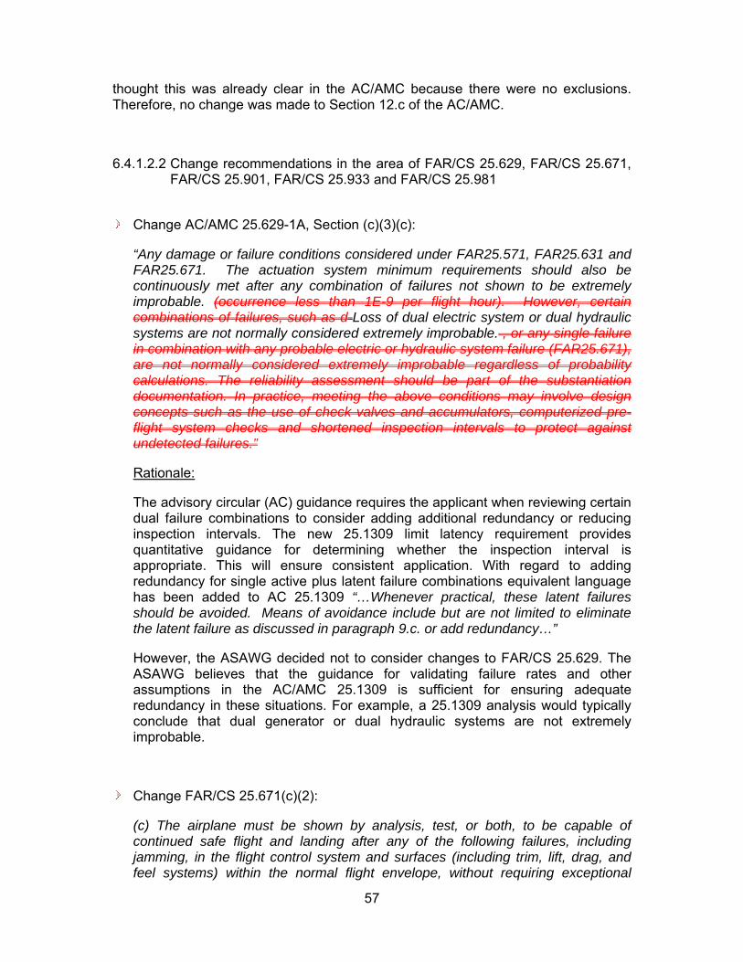
57
thought this was already clear in the AC/AMC because there were no exclusions. Therefore, no change was made to Section 12.c of the AC/AMC.
6.4.1.2.2 Change recommendations in the area of FAR/CS 25.629, FAR/CS 25.671, FAR/CS 25.901, FAR/CS 25.933 and FAR/CS 25.981
Change AC/AMC 25.629-1A, Section (c)(3)(c):
“Any damage or failure conditions considered under FAR25.571, FAR25.631 and FAR25.671. The actuation system minimum requirements should also be continuously met after any combination of failures not shown to be extremely improbable. (occurrence less than 1E-9 per flight hour). However, certain combinations of failures, such as d Loss of dual electric system or dual hydraulic systems are not normally considered extremely improbable. , or any single failure in combination with any probable electric or hydraulic system failure (FAR25.671), are not normally considered extremely improbable regardless of probability calculations. The reliability assessment should be part of the substantiation documentation. In practice, meeting the above conditions may involve design concepts such as the use of check valves and accumulators, computerized pre-flight system checks and shortened inspection intervals to protect against undetected failures.”
Rationale:
The advisory circular (AC) guidance requires the applicant when reviewing certain dual failure combinations to consider adding additional redundancy or reducing inspection intervals. The new 25.1309 limit latency requirement provides quantitative guidance for determining whether the inspection interval is appropriate. This will ensure consistent application. With regard to adding redundancy for single active plus latent failure combinations equivalent language has been added to AC 25.1309 “…Whenever practical, these latent failures should be avoided. Means of avoidance include but are not limited to eliminate the latent failure as discussed in paragraph 9.c. or add redundancy…”
However, the ASAWG decided not to consider changes to FAR/CS 25.629. The ASAWG believes that the guidance for validating failure rates and other assumptions in the AC/AMC 25.1309 is sufficient for ensuring adequate redundancy in these situations. For example, a 25.1309 analysis would typically conclude that dual generator or dual hydraulic systems are not extremely improbable.
Change FAR/CS 25.671(c)(2):
(c) The airplane must be shown by analysis, test, or both, to be capable of continued safe flight and landing after any of the following failures, including jamming, in the flight control system and surfaces (including trim, lift, drag, and feel systems) within the normal flight envelope, without requiring exceptional

58
piloting skill or strength. Probable failures must have only minor effects and must be capable of being readily counteracted by the pilot.
(2) Any combination of failures not shown to be extremely improbable. Furthermore, the flight controls must comply with FAR25.1309(b)(4). This paragraph excludes failures of the type defined in (c)(3). excluding jamming (for example, dual electrical or hydraulic system failures, or any single failure in combination with any probable hydraulic or electrical failure).
Change FAR/CS 25.671(c)(3)(iii):
(c) The airplane must be shown by analysis, test, or both, to be capable of continued safe flight and landing after any of the following failures, including jamming, in the flight control system and surfaces (including trim, lift, drag, and feel systems) within the normal flight envelope, without requiring exceptional piloting skill or strength. Probable failures must have only minor effects and must be capable of being readily counteracted by the pilot.
(3)Any failure or event that results in a jam of a flight control surface or pilot control that is fixed in position due to a physical interference. The jam must be evaluated as follows:
(iii) In the presence of a jam considered under this sub-paragraph, any combination of failures that are catastrophic shall comply with FAR25.1309(b)(4).additional failure states that could prevent continued safe flight and landing shall have a combined probability of less than 1 in 1000.
Change Post TAEIG draft AC/AMC 25.671:
If the guidance defined under the AC/AMJ 25.671 post TAEIG draft is adopted then it is recommended that all references to specific risk be deleted and a pointer be provided to the proposed revision to AC/AMC 25.1309 (see attached).
C:\Safety\TAEIG WG\Final Report\Latent\A
Rationale:
This regulation is associated with an issue paper and an ARAC FCHWG recommendation that implement limit latency and/or residual risk methodology. The ARAC FCHWG recommendation requires that in the presence of any single failure the sum of all remaining failures meet 1/1000 probability. This is a limit latency and residual risk requirement. The issue paper requirement requires that for any single failure in each individual failure sequence (e.g. cut set) that the remaining failures in that sequence be Remote. The issue paper requirement is a residual risk only requirement.

59
These previous means of compliances provide different criteria and different methodologies for calculating the criteria. The new 25.1309 regulation adopts both limit latency and residual risk criteria. The residual risk numerical objective of Remote is chosen using ARAC methodology of calculating sum of all remaining failures. This is more conservative than the existing standards, but has a reduced scope. Unlike the existing means of compliance, it does not apply to active – active failure combinations. Eliminating the active – active failure conditions from the specific risk criteria does not impact the over all safety benefits of the analysis because the conditions of concerned are covered under the average risk criteria of FAR/CS 25.671(c)(1) & (c)(2) and FAR/CS 25.1309(b)(1). With regard to residual risk the ASAWG was only concerned with situations in which the airplane could be operating one failure away from a Catastrophe for multiple flights.
Existing means of compliance for flight controls only consider residual risk for single latent failures. These practices do not apply residual risk assuming the presence of multiple latent failures. The ASAWG has kept to this philosophy in regards to quantitative residual criteria. As a result residual risk has the most impact on dual failures. Therefore the ASAWG has limited the residual risk application to dual failure combinations.
The ASAWG new limit latent regulation applies to individual latent failures rather than the sum of latent failures associated with a single active failure. The impact of 1/1000 on exposure times associated with multiple latent failure combinations was considered not significant. Therefore the limit latency requirement is also limited to dual failure combinations.
To be consistent with average risk calculation model the ASAWG decided not to adopt the maximum dormant model for latent failures. This is not a significant issue because this did not represent an order of magnitude change in inspection intervals. Further the applicant would not run two different types of fault tree calculations for latency. Therefore the application of maximum dormant model could effectively change fault trees from an average risk calculation to a maximum risk calculation by practice if not by requirement.
The change to FAR/CS 25.671(c)(3)(iii) affects dual failures where the active failure of the jam (normally encountered) is alleviated by a device that can be latent for more than one flight. The change is consistent with how other single failure plus latent failure combinations are addressed by the ASAWG. It is also consistent with the scope of the original rule.
Replace FAR25.901(c) with:
(c) The powerplant installation must comply with FAR25.1309(b), except that the effects of the following need not comply with FAR25.1309(b): (i) Engine case burn through or rupture; (ii) Uncontained engine rotor failure; and (iii) Propeller debris release.
Introduce AC/AMC 25.901:

60
C:\Safety\TAEIG WG\SR Meet 12\Latent\25
Rationale:
It was decided that FAR25.901 does not have latent specific risk criteria included in the rule; however, there is policy that require the review of latent related specific risk; therefore, a recommended change is provided. In addition, upon application of the proposed AC/ACJ 25.901 (see attached) compliance to the remote requirements of the proposed 25.1309(b)(4) has been included.
ASAWG Recommends adoption of the related ARAC PPIHWG and SDAHWG Recommendations as modified by the ASAWG recommendations made elsewhere in this report. Adoption of the ASAWG recommendations regarding FAR/CS 25.1309 would result in a level of safety for powerplant systems at least equivalent to that provided by the current interpretation of FAR/CS 25.901(c) while facilitating a more consistent and objective means of demonstrating compliance. For example, the “no single failure” requirement would be covered by the revision to FAR/CS 25.1309(b) proposed by ARAC SDAHWG and clarified by ASAWG recommendations. The avoidance of “latent plus one” failure conditions would be covered by the ASAWG recommendation to eliminate significant latent failures wherever practical. In addition the ASAWG recommendation would provide a more objective and hence consistent maximum acceptable residual risk when operating one failure away from a catastrophe.
Replace FAR/CS 25.933(a)(1) with:
(a) For turbojet reversing systems (1) Each system intended for ground operation only must be designed so that either— (i) The airplane can be shown to be capable of continued safe flight and landing during and after any thrust reversal in flight; or (ii) It can be demonstrated that inflight thrust reversal complies with FAR25.1309(b)(1) & FAR25.1309(b)(4). is extremely improbable and does not result from a single failure or malfunction. Introduce AC/AMC 25.933:
Replace Sections 8.b.2 and 8.b.3 of the attached TAEIG PPIHWG AC 25.933X with a Section 8.b.2 as follows:
In accordance with Arsenal Draft of AC/AMC 25.1309, Section 9.b.(6), whenever practical, latent failures should be avoided. It has traditionally been deemed practical to avoid catastrophic in-flight thrust reversal failure conditions due to any “single latent plus single active” (a.k.a “latent plus one”) failure combination.

61
C:\Safety\TAEIG WG\SR Meet 12\Latent\TA
Rationale:
A change to FAR/CS 25.933(a)(1)(ii) was recommended because the rule combined with recent policy implies latent specific risk criteria should be applied to thrust reversers. This policy is based on earlier ARAC recommendations currently being used and requires the review of latent related specific risk. Therefore, the introduction of the ARAC PPIHWG version of AC/ACJ 25.933 with the deletion of Sections 8.b.2 and 8.b.3 was provided to ensure consistency across the Industry and systems.
ASAWG Recommends adoption of the related ARAC PPIHWG and SDAHWG Recommendations as modified by the ASAWG recommendations made elsewhere in this report. Adoption of the ASAWG recommendations regarding FAR/CS 25.1309 would result in a level of safety for powerplant systems at least equivalent to that provided by the current interpretation of FAR/CS 25.933(a)(1)(ii) while facilitating a more consistent and objective means of demonstrating compliance. For example, the “no single failure” requirement would be covered by the revision to FAR/CS 25.1309(b) proposed by ARAC SDAHWG and clarified by ASAWG recommendations. The avoidance of “latent plus one” failure conditions would be covered by the ASAWG recommendation to eliminate significant latent failures wherever practical. In addition the ASAWG recommendation would provide a more objective and hence consistent maximum acceptable residual risk when operating one failure away from a catastrophe.
Change to FAR/CS 25.981(a)(3):
(a) No ignition source may be present at each point in the fuel tank or fuel tank system where catastrophic failure could occur due to ignition of fuel or vapors. This must be shown by: (3) Demonstrating compliance with FAR25.1309(b)(1) & FAR25.1309(b)(4). could not result from each single failure, from each single failure in combination with each latent failure condition not shown to be extremely remote, and from all combinations of failures not shown to be extremely improbable. The effects of manufacturing variability, aging, wear, corrosion, and likely damage must be considered.
Changes to AC/AMC 25.981-1/2:
The ASAWG did not have the experience to recommend changes to AC/AMC 25.981-1/2 but recognize the need to update these to at least result in more realistic consideration of the conditional probability that the presence of a potential ignition source will result in a catastrophic fuel tank explosion.
Rationale:

62
This regulation has been the discussion of many certification activities since it was adopted and in many cases the criteria could not be fully satisfied requiring exemptions of the rule. In addition, this rule is not harmonized between the FAA and EASA resulting in further disconnects between manufacturers. Therefore, all specific risk criteria have been eliminated from the rule and it is recommended that a similar task be done in the guidance.
However, it was agreed within the group that there was not adequate knowledge in the ASAWG of the criteria that went into the definitions related to a potential ignition source and how probabilities are related to these. The requirements provided in FAR/CS 25.1309(b) and the guidance of Arsenal Draft of AC/AMC 25.1309 are considered to provide adequate coverage for latent failure conditions.
6.4.1.3 Benefits of the Recommendations
ASAWG has made trade offs between invalidating existing designs, increasing the analytical burden and being conservative when deriving the recommended airplane level specific risk criteria. The key benefit Industry saw after several years of review and discussion was harmonization and consistency across all systems and between various regulation bodies. Unlike previous working groups that were tasked to respond to a specific event or threat that had occurred, this effort is more of a harmonization across the aircraft and regulatory bodies. Therefore, the identification of potential measurable safety benefits was not identified.
The proposed changes:
Eliminates the inconsistent application of various residual risk criteria via IPs and CRIs ranging from 1E-3 to 1E-6. Manufacturers and Regulators alike spend excessive time early in the airplane development cycle negotiating these based on their specific airplane and system designs. The cost related to this was impractical for the manufacturers and regulators to quantify but involve both non-recurring labor cost and recurring equipment costs.
Increases safety by providing applicants and regulators clear guidance that can be applied consistently across systems.
Avoids non-standardized system safety assessments across various critical systems making it hard to properly evaluate at the aircraft level, which could cause conflicting interpretations for conducting system safety assessments in aircraft certification programs, Currently, manufacturers performing aircraft level analysis or highly integrated system level analysis based on the worst case criteria. This has the potential to add cost and complexity to the systems. The actual value of this savings could not be quantified when looking at existing systems.
Provides for an acceptable level of safety across all systems and applications. This is intended to be adequate for coverage of all systems related to specific risk and minimize the generation of new rules, special conditions, IPs, CRIs, etc..., in the future.

63
6.4.1.4 Costs Impacts of the Recommendations
All the members of the ASAWG were requested to provide a Cost and Benefits (C/B) analysis in 2010 US dollars based on the proposed changes. The electronic suppliers abstained from the process on the basis they respond to the airframer’s requirements and any cost would be shown at that level. The engine suppliers did not provide any C/B analysis but one did provide a dissenting opinion (see Section 6.4.1.6) that was later addressed and closed with all the engine manufacturers supporting the proposal.
When reviewing the costs associated with the changes, manufacturers reviewed existing certified aircraft and determined what system or maintenance interval would be changed through the review of already released fault trees. The cost provided below is the cost to bring that airplane up to the proposed changes. Change cost was considered conservative but appropriate because many times manufacturers try to carry system designs forward to new models.
Likewise, potential savings that could be realized in systems that were driven by the more stringent requirements that got applied on an applicant by applicant basis or were the existing system level requirements have actually been relaxed was considered minimal. The rationale for this position was again the practice of the manufacturers not to make changes to already certified designs that could still be applied to a new product.
The cost benefit analysis performed by the various airframe members of the Working Group could be categorized into three unique responses:
Large aircraft over 100,000 lbs
New Business FBW aircraft
Smaller Business Jet aircraft
Large aircraft over 100,000lbs:
Airbus, Boeing and Embraer are the airframers that make up this sub-group. In all cases they identified potential impact to operations and/or the design of the aircraft. There were two methods recognized to resolve any impacts caused by the changes recommended. One was to change the design practices that were previously applied to existing aircraft resulting in potential increase in the cost of the aircraft and the other was to change maintenance intervals thus impacting the operational cost of the aircraft. These two methods are not exclusive of one another and because design philosophies vary from one airframer to another they will not be consistent from one another. However, there was a definitive resultant impact that can be derived from the three C/B analysis provided, they are:
Design Impacts:
o Total Non-Recurring Cost per Model range from $13M to $20M.
o Total Recurring Cost per Airplane range from $34K to $70K.
Operational Impacts:

64
o Added Maintenance Cost per Airplane per year is approximately $800.
o Added Fuel Burn per Airplane per year range from $2K to $3K.
The detail cost analysis worksheets that went into this summary are located in Appendix A section 6.4.5.1.
New FBW aircraft operating mainly under Part 91 and 135:
Dassault and Gulfstream provided the C/B analysis for this sub-group. For these two manufacturers, the only cost impact identified was a one time nonrecurring cost to update the policies and procedures to include automated software used to perform the analysis. Dassault identified this cost to be on the order of $100,000.
The detail cost analysis worksheets that went into this summary are located in Appendix A section 6.4.5.2.
Smaller aircraft operating mainly under Part 91 and 135:
There are several manufactures that make up the working group that have aircraft in this category; however, only one identified potential cost they may incur in future aircraft development. Their costs were:
Design Impacts:
o Total Non-Recurring Cost per Model was approximately $9M.
o Total Recurring Cost per Airplane was approximately $1.6M.
Operational Impacts:
o Added Maintenance Cost per Airplane per year is approximately $25K.
o Added Fuel Burn per Airplane per year is approximately $60K.
The detail cost analysis worksheets that went into this summary are located in Appendix A section 6.4.5.23.
6.4.1.5 Alternatives considered and why they weren’t chosen
The alternative of not making any of the changes described in section 6.4.1.2 was considered at each step of the review and recommendation development process of this tasking. In each case, the pros and cons were identified and recorded in the report under Task 2 and Task 3. The final Latent Task 4 change recommendation was established by taking into account the comments from all organizations as received during Task 4. There were only two areas that were identified in Task 3 for potential change that did not finally result in a change recommendation. They were FAR/CS 25.783 and FAR/CS 25.1709.
No change to FAR/CS 25.783:

65
Rationale:
As of today, FAR/CS 25.783 does not have latent specific risk criteria included in the rule. Though there was numerous safety requirements, both quantitative and qualitative, for fuselage doors, the Working Group did not see any peculiar requirements other than employing the average risk and no single failure criteria of FAR/CS 25.1309. It was also recognized by the Working Group, that applying specific average risk or no single failure safety design criteria to specific features within a specific functional area was appropriate. Section 25.783 requires that "Each door that could be a hazard if it unlatches must be designed so that unlatching during pressurized and unpressurized flight from the fully closed, latched, and locked condition is extremely improbable." In addition, the failure criteria in 25.1309(b)(4) would apply to any door whose opening would be catastrophic.
No change to FAR/CS 25.1709:
Rationale:
As of today FAR/CS 25.1709 does not have latent specific risk criteria included in the rule.
The FAR/CS 25.1709 is new and was never applied up to now. ASAWG sees the need for getting experience from first applications before any change should be foreseen.
The AC/AMC 25.1709 is giving means of compliance for the FAR/CS 25.1709. These means of compliance are giving quite detailed recommendation how to comply with FAR/CS 25.1709 in a qualitative approach, but there is no recommendation to comply in case of quantitative aspects. Any future foreseen change for the FAR/CS 25.1709 should lead also to detailed changes for the AC/AMC 25.1709 to make possible a consistent interpretation regarding appropriate means of compliance.
6.4.1.6 Dissenting Opinion and Discussion
6.4.1.6.1 Cessna
Cessna submitted the following dissenting opinion:
Cessna has the unique position of being the only aircraft OEM to certify three all new business jets using the process spelled out in SAE ARP 4761 as a means of showing compliance to 1309. At the same time, Cessna was the only aircraft OEM to vote NO on the latent section on the Task 4 report. The purpose of this dissenting opinion is to explain why.

66
It has not been demonstrated to Cessna that the following proposed AC and rule change results in a net safety increase or that it can be supported by a cost benefits analysis:
“25.1309 b(4) For each catastrophic failure condition that results from two failures, either of which is latent for more than one flight, it must be shown that -
(i) Given any single latent failure has occurred, the combined probability per flight hour of catastrophe due to any subsequent single failure is remote; and
(ii) The probability of occurrence of the latent failure is on the order of 1/1000 or less.”
Typical fault trees today used to show compliance to 1309 contain well over 1000 basic events; several hundred of those basic events may be latent. While the proposed AC changes do “bound the problem” and limits the “what if’s” to be considered, the applicant is forced to analyze and document the “bounded” cut sets. If the AC “bounds the problem” as stated in the Task 4 report, then typically there are 100 cut sets of interest for each catastrophic functional failure condition. Since each all new aircraft has close to 100 catastrophic functional failure conditions, the proposed process results in ~10,000 cases to look at (100 cut sets times ~100 functional failure conditions). While the fault tree program generates these, the cut sets have to be exported into another program (i.e. spreadsheet) and additional analysis has to be generated and documented.
Of course, as stated in the report “An alternative but more conservative method would be to rerun the fault tree probability calculation assuming for each model rerun that a different latent basic event had failed”. It is clear to Cessna, that no applicant will run and document ~10,000 additional fault trees.
In the spring of 2009, Cessna ran a test case to evaluate the costs and benefits of this activity. The aircraft used for this evaluation was Cessna’s most recent all new part 25 aircraft. The process this aircraft was evaluated against was the leading contender the ASAWG group was proposing. Cessna’s estimate is that it would take close to 2 million dollars to complete and document the analysis for an all new business jet aircraft. The “final” method published in the ASAWG task 4 report is 3 to 4 times more “work intensive” than what was run in the 2009 trial. Our “final” estimate to conduct this analysis on a part 25 business jet is 6 to 8 million dollars. For Cessna, this is about half the retail cost of a new part 25 aircraft.
It should be pointed out that all 110 catastrophic functional failure conditions were examined and none of them were flagged as being “non compliant” to the proposed rule. Cessna’s position is that this is an additional cost without a proportional safety benefit for part 25 business jets. Cessna can not support spending an additional 6 to 8 million dollars on certification when the result of the additional cost does not provide any safety benefit. Cessna is not taking this position because it has a tried and true design that would no longer be compliant. Cessna is taking this position because the documentation that Cessna would have to produce to show compliance is not supported by a cost benefits analysis and outweighs any gain to be had by the “harmonization and consistency” the Task 4 report proposes.
In some non-ETOPS two engine applications, it should be pointed out that if a latent failure causes an in flight shut down of an engine, the other engine will not be able to

67
meet the remote criteria of 1e-5. Most non-ETOPS part 25 engines have a failure rate close to 2~3e-5 per flight hour. When this is summed with the other residual risks, it is clear that the design will not support the requirement. This will introduce redundancy (a third engine) or system complexity (monitoring that has to be better than 2~3e-5). This will likely have an adverse effect on safety since most accidents are not caused by system failures, but by the crew not responding to a system fault correctly.
Finally, the ASAWG group failed to address the case where one latent combines with more than one active in more than one catastrophic functional failure condition. To demonstrate, let us assume that the same latent appears in a landing gear and flight controls catastrophic functional failure condition cut set listing that needs to be evaluated. In this example, the report does not address what the applicant would do, and it is open to interpretation. Since this is not explicitly addressed in the report, proposed preamble or proposed AC, Cessna is very concerned that the regulators would force the applicant to show that the total residual risk summed across all the functional failure conditions where the latent occurs is remote. In this case, our cost estimate would increase by 2 million to between 8 and 10 million dollars, or half the retail cost of a part 25 business jet, without a safety benefit.
ASAWG disposition of Cessna Dissenting opinion:
This response to Cessna's dissenting opinion is not a point by point rebuttal but more of a philosophical and general industry response.
First, the comment that Cessna is the only "aircraft OEM to certify three all new business jets using process spelled out in SAE ARP 4761 as a means of showing compliance to 1309." is not relevant and is misleading. First, both Airbus and Dassault have both certified Part 25 aircraft not only to the tools called out in ARP4761 but to the system engineering process called out in ARP4754 and the "diamond" version of AC/AMC 25.1309. In addition, both Boeing and Gulfstream have mature Part 25 aircraft certification programs ongoing with the FAA using both ARP4761 and ARP4754 modified to reflect the latest changes being made in Revision A of ARP4754 and CS25.1309. Finally, the focus of the ASAWG efforts have been harmonization from one system requirement to another as it relates to the aircraft system level requirements of 14CFR 25.1309. The fact that specific and unique safety analysis over and above the requirements of 25.1309 and AC 25.1309-1A must be performed for systems such as flight controls, thrust reversers, engines etc. is not addressed by Cessna.
In the cost analysis reviews done by all the current airframe manufacturers developing Part 25 aircraft it was recognized that there would be potential increase in scope and work related mainly avionics systems. However, because of the increasing integration and complexity of avionics support of flight controls, engine control, thrust reverser deployment, etc. the potential increase was acceptable provided the criteria established was completely implemented such that no existing or new system peculiar specific risk criteria for latent conditions would be specified on new projects.
Finally, to respond to Cessna's two concerns about implementation of the recommended rule. First, the engine example was reviewed in great detail with all four of the engine manufacturers expressing their concerns. The discussion on GE's

68
dissenting opinions is examples of these discussions of concerns and how they were resolved and dealt with. The qualitative term "remote" was used in the proposed 14CFR 25.1309(b)(4)(i) in lieu of a quantitative term such as less than 1E-5 to permit the OEMs and regulators to use the historical application of "remote" to mean "of-the-order-of" or "on-the-order-of" thus recognizing the potential for state of the art engines satisfying the requirement by being 2 or 3 E-5.
Cessna's final concern of a latent failure condition in a functional system that supports several aircraft systems that have independent catastrophic conditions was raised during Group discussions and the residual risk criteria from 25.1309(b)(4) is clearly seen as limited to one failure condition and has not to be applied across several failure conditions, where the same latent failure occurs. The proposed 25.1309(b)(4) starts therefore with "For each catastrophic failure ....".
For the reasons stated above, the ASAWG still sees merit in supporting the proposed changes to address latent specific risk in lieu of the concerns and cost that Cessna has identified.
6.4.1.6.2 EASA
EASA submitted the following dissenting opinion:
Ref: Section 6.4.1 of the draft ASAWG Final report produced after Cologne Meeting
The following documents EASA dissenting opinion on one particular aspect of the latent failure proposal regarding modification of 25.933(a)(ii) and associated advisory material.
This must be understood in the context of CS-25 updating following the recommendations from the ASAWG. It also relates to the particular situation of CS-25 (compared to FAR 25) where many of the previous recommendations coming from ARAC SD&A HWG and PPIHWG have already be incorporated, notably the 25.1309 one and the associated AC/AMC “Diamond” version as proposed by the SD&A HWG, 25.901 and 25.933 as proposed by the PPIHWG.
EASA is supportive of the concept of having an aircraft level harmonized approach for dealing with specific risk/latent failures.
As part of the latent failure task package, the ASAWG group proposal introduces a new 25.1309(b)(4) that specifies acceptable criteria for limiting latency/residual risk for a catastrophic failure condition resulting from the specific combination of two failures either of which can be latent for more than one flight.
The other aspects like minimization of latent failures, elimination of those latent failures whenever judged practical and considerations of multiple latents in combination with a single active have been included in the AC, but not formally covered in the rule following the deliberations of the Working Group.
Proposed revision to 25.933(a)(1)(ii) makes direct reference to compliance with 25.1309(b)(1) & (b)(4) for in-flight thrust reversal when “reliability option” is chosen. The AC/AMC FARFAR 8(b)(2) and 8(b)(3) “specific risk” criteria are proposed to be

69
deleted and reference is made to AC/AMC 25.1309 provisions that deal with 25.1309(b)(4) compliance.
As formally proposed, the revision to 25.933(a)(1)(ii) could be seen as a reduction of safety compared to what is currently achieved by compliance with CS 25.933(a)(1)(ii). This is mainly driven by the fact that the proposed 25.1309(b)(4) only addresses the combination of two failures, either of which could be latent.
Existing FAR 8(b)(2) would not allow for the configuration regulated through 25.1309(b)(4) (there should not be a combination of one active and one latent that results in in-flight thrust reversal). Existing FAR 8(b)(3) limits latency exposure for cases of three failures or more. Both paragraphs relate to currently accepted practices that have been shown to be practical and also introduced to cover adverse service experience.
Based on the currently proposed 25.1309(b)(4), provisions of the existing AMC FARFAR 8(b)(2) and 8(b)(3) should be kept as providing a clear reference of currently accepted practices for thrust reversers.
Other options may be available in case a more robust 25.1309(b)(4) is introduced.
ASAWG disposition of EASA Dissenting opinion:
When developing SR criteria and methodologies it was recognized by the ASAWG that the most conservative standard would not necessarily be adopted. Each area of design: Flight controls, TRs, etc had what was thought to be an acceptable standard and means of compliance for critical failure conditions. To state that the level of safety for 25.933 is unacceptably compromised implies that other existing standards today are unsafe. This is not a view shared by those other disciplines.
Dissent relates to acceptable standard, reference T/Rs. See response to FAA OPINION #2.
6.4.1.6.3 FAA
FAA dissenting opinion and ASAWG disposition:
OPINION #1:
The FAA has concerns about the term “on the order of” directly being in the rule. It makes little sense to define a specific numerical threshold and then intentionally make it vague. This will lead to the obvious question: what does “on the order of” mean numerically? The example in the Appendix clearly shows the intent is not to exceed the 1/1000 criterion, except in rare cases whose rationale can be presented as illustrated in the last sentence of this paragraph.
In lieu of using “on the order of,” the FAA would prefer to preface the 25.1309(b)(4)(ii) requirement with “Unless otherwise approved by the authority.” This would achieve the same objective, which is flexibility in rare cases.
ASAWG disposition to OPINION #1:

70
There was a lot of discussion over 3 years in the Group with the use of qualitative terms (e.g. Probable, Improbable, Remote, Extremely Remote, and Extremely Improbable) in lieu of the quantitative terms (see the preamble in Section 6.4.1 for more discussion on this). However, the use of qualitative term "probable" to mean "of-the-order-of 1E-3 or less" was not acceptable because the term "probable" is used several ways so the actual definition used in AC/AMJ 25.1309 was used as the requirement. The term "of-the-order-of" has been used in the Industry since Amendment 25-23 was released to 14CFR25 in 1970.
OPINION #2:
As stated at meeting #14 in Cologne, we agree with this AC material that “whenever practical, these latent failures should be avoided.”, but we are concerned this will not be enforceable and is “rulemaking by AC” given the intent of the AC material. Moreover, EASA and FAA both conveyed to the WG that without a means to back this up, the level of safety provided by the ARAC 25.933 recommendation could be unacceptably compromised. We re-iterate the necessity and importance of having a rule requiring elimination or minimization of significant latent failures unless impractical.
ASAWG disposition to OPINION #2:
The first part of dissent relates to enforcement of minimization criteria. The application of fail safe design philosophy as well as minimization of latency has been enforced by Industry for a number of years though it is not a rule. The rationale by the Group was to develop a minimum quantitative criterion that could be applied to all systems. The establishment of this quantitative requirement was in response to Industry's desires to have a known boundary that can be black and white and that cannot be passed. Minimization statements are too open but are recognized as good design practices and one that Industry implements. This is the reason for not putting an undefined term in the regulation; the minimum requirement is in the regulation.
The second part of dissent relates to acceptable standard. When developing SR criteria and methodologies it was recognized that ASAWG would not necessarily adopt the most conservative standard. Each area of design: Flight controls, TRs, etc had what was thought to be an acceptable standard and means of compliance for critical failure conditions. To state that the level of safety for 25.933 is unacceptably compromised implies that other existing standards that do not employ the same criteria as the thrust reversers are not as safe as the thrust reversers. This is not a view shared by those other disciplines and why combinations of several of these standards were used to derive the final recommendation.
OPINION #3:
The FAA continues to believe that revising AC 25.629-1A should only be done after consulting with the flutter community.
We therefore ask that each OEM represented on the ASAWG contact their flutter experts and explain the ASAWG proposed changes to 25.671 and 25.1309 and associated guidance, and the proposed solution for AC 25.629. The ASAWG-proposed change to AC 25.629 should be discussed as well as the FAA proposal, shown below. We also ask that those flutter experts, or appropriate representatives,

71
then contact Todd Martin ([email protected]) to provide their opinion on changes to AC 25.629.
FAA-proposal for AC 25.629-1A, Section 5.c.(3)(c):
“Any damage or failure conditions considered under FARFAR 25.571, 25.631, 25.671, and 25.1309.
The actuation system minimum requirements should also be continuously met after any combination of failures not shown to be extremely improbable (occurrence less than 10-9 per flight hour). However, certain combinations of failures, such as dual electric or dual hydraulic system failures, or any single failure in combination with certain electric or hydraulic system failures, are not normally considered extremely improbable based on service history. Therefore, a qualitative assessment should also be conducted in addition to the quantitative assessment. The latent failure criteria of FAR 25.1309(b)(4) must also be considered. The reliability assessment should be part of the substantiation documentation.”
ASAWG disposition to OPINION #3:
The concern that the flutter communities are not involved is not understood by the ASAWG. The ASAWG Industry members have been coordinating the proposed changes with the various functional organizations within their respective Companies since the beginning and is the reason for highlighting in the case of flutter 14CFR 25.629 and AC 25.629-1A for change.
The FAA proposal seems to want to retain specific risk criteria for active – active failure combinations, i.e. certain active – active failures that are not extremely improbable based on service history. This may be problematic if it is interpreted that ALL single failures in combination with certain electric or hydraulic system failures are not extremely improbable. It is far better to follow the 1309 AC process in making this determination. It is consistent with generating a standard means of compliance which was one of the primary objectives of the ASAWG.
OPINION #4:
Firstly, the proposed wording for (iii) developed in Cologne would need to be modified, as shown below, to be consistent with the ASAWG intent and the proposed AC 25.671 changes.
In the presence of a jam considered under this sub-paragraph, any single latent failure state that could prevent continued safe flight and landing when combined with the jam must satisfy the specific risk criteria of FAR/CS 25.1309(b)(4)(ii).
Secondly, even with this change, the FAA does not agree to change the FCHWG recommendation on 25.671(c)(3) for the following reasons:
(1) While the FCHWG proposal was deliberated exhaustively by numerous organizations and disciplines, there’s been no such deliberation on the ASAWG proposal as it was developed near the end of the Cologne meeting;
72
(2) the FCHWG proposal specifically addresses jams, which are a unique phenomena for which unique criteria are appropriate - the 1/1000 criterion would essentially apply to jam alleviation systems; (3) it would be more clear to simply state the requirement in 25.671(c)(3) rather than point to a subparagraph of 25.1309.
The FAA will deliberate further on both the FCHWG and ASAWG proposals for 25.671(c)(3), and will work with the authorities to develop the final harmonized proposal.
ASAWG disposition to OPINION #4:
The suggested change would limit the scope of latent specific risk to only the specific risk portion and not include residual risk. Per the definition in the FCHWG AC jams are considered a type of failure and include jam valves, etc; therefore, this condition should not have peculiar criteria. For the jam conditions resultant from external events then the ASAWG does concur with the FAA’s response in those conditions are “unique phenomena” and should be covered under the proposed AC/AMJ 25.1309 paragraph 11g or even in a peculiar criteria under 25.671 and can be appropriately handled by the FCHWG. As stated before, the intent is not to have specific application for one system but not another so the general reference to FAR/CS 25.1309(b)(4) and not just FAR/CS 25.1309(b)(4)(ii).
The statement that the CFR 25.671 was not discussed exhaustively does not seem relevant. The specific risk criteria have been discussed exhaustively and therefore the only relevant question would seem to be are the SR criteria applicable to this rule. Is it a latent plus one failure condition? It is not clear whether the second point is implying that 1/1000 criteria should be applied at the system level rather than the basic event level. However this would be inconsistent with ASAWG objectives.
6.4.1.6.4 Garmin
Garmin submitted the following dissenting opinion:
OPINION #1:
Section 6.4.1 Last paragraph:
Comment: Should not the comma after the word “yet” be after the word “aircraft”?
Dissent: If the change is not significant but some additional rules not in the existing airplane certification basis are determined necessary for the STC has not the applicant got a new certification basis for those aircraft affected by the STC? Garmin would say yes and per this wording would have to pick up the SR rule.
Recommendation: Finally, because these changes provide no measurable safety reduction at the aircraft, yet include the general system requirements provided in FAR/CS 25.1309 that are applicable across all systems, they should not be applied retroactively. For changes to existing TC/STC, the application of this proposed amendment of FAR/CS 25.1309 and associated guidance should only be required for those changes determined to be significant as defined by FAR/CS 21.101(b).

73
ASAWG disposition to OPINION #1:
This was the intent of this paragraph. It is the understanding of the ASAWG that when an applicant decides to step up to new regulations and/or guidance when not required to per 14CFR21.101(b) that these type of specific certification basis issues would be discussed and resolved as part of the applicants submittal of the change as not significant.
6.4.1.6.5 General Electric
GE dissenting opinion and ASAWG disposition:
C:\Safety\TAEIG WG\Final Report\Latent\G
The following is ASAWG's response to GE's dissenting opinion with GE's position in italics and green color. Since the development of this response, GE has reviewed the proposal and discussed with the other engine manufacturers on the ASAWG. GE currently concurs, that modern engine designs have good latency and residual risk levels on a fleet average basis and manage to appropriate deterioration levels. However, GE still has some concerns with the actual implementation, given that the specific risk of concern definition is too broad, potentially driving system complexity or maintenance action for new certifications that could be overly conservative and impact reliability more than they improve safety.
Certification Inconsistencies
“The primary ASAWG position has been that specific risk work was to address inconsistencies in the certification process, and was not addressing known accidents that could have been avoided with specific risk. While GE agrees that the FAA and other authorities should treat all applicants consistently, we disagree that consistency should require the exact same methodology to be used for mechanical and electronic systems, as an example. Mechanical systems with well understood revenue service experience have been safely certified to differing requirements than more complicated electronic systems.”
ASAWG was specifically restricted from considering the role of specific risk in historical accidents. We were tasked to harmonize the specific risk analysis methods and criteria across all aircraft system. However, it is recognized that, while the criteria should be the same regardless of the technology utilized, there will be differences in acceptable methodologies as a function of the technology, novelty and complexity. These accommodations are already inherent within the AC25.1309 guidance.
Golden Rule Numbers
“It was stated that specific risk changes were not intended to change the < 1E-9 level for average fleet risk. From the beginning, definitions for “specific risk “and “specific

74
risk of concern” were not accurate. As a result, the latency and residual risk numbers would drive the fleet average risk lower than 1E-10. GE’s primary issue is with the numerical values defined in what was referred to as the “Golden Rules. The minimum latency should have been no lower than 1E-2, instead of 1E-3. The minimum residual risk should have been 1E-4, instead of 1E-5.
For example, the ETOPS upper limit of 0.02 IFSDs per 1000 flight hours that the industry has been safely managing to, translates to a potential residual risk of 2E-5 when left with one engine. An engine just meeting ETOPS criteria, IFSD rate of 5E-5 to 2E-5/hour, would fail the golden rule on residual risk. This is a simple example that illustrates how the more restrictive specific risk numbers would drive the fleet average risk lower than 1E-10, and preclude the use of design architectures which have already demonstrated their safety over decades.”
ASAWG believes that GE provides no relevant evidence to compel ASAWG to increase the limiting latency or residual risk criteria.
The ETOPS residual risk example is an active-active failure case specifically covered elsewhere in our report, but to which FAR25.1309(b)(4) does not apply.
Furthermore, the quoted ETOPS criteria is not really a comparable residual risk criteria, but rather a threshold indicating sufficient design and operational maturity to enter ETOPS. However, the authorities still require any potentially endemic cause of IFSD be fixed to further reduce (i.e. minimize) the IFSD rate. This in turn has resulted in engine run reliabilities much better than these thresholds in most cases.
For further explanation of the relevant applicability of the "Golden Rule Numbers”, see our response to your “Cost Benefit Analysis” comments.
Specific Risk of Concern
“GE also has issues with the definitions associated with several terms used by the ASAWG. To define “specific risk of concern” as “the risk is greater than the average probability criteria provided in AC 25.1309 Arsenal for hazardous and catastrophic failure conditions” is incorrect since much of the 3 sigma risk deviation above the average occurs frequently and is no problem. By definition, half of any fleet will have risk above average. The specific risk of concern should be limited to particular conditions that exceed 1E-4. Again, this is a simple example that illustrates how the definition of specific risk of concern would drive the fleet the average risk lower than 1E-10.”
These definitions were developed to help ASAWG “scope” the task at hand. While we would agree that what is truly a specific risk of concern is one that does not meet the proposed FAR25.1309(b)(4) criteria, that was not the purpose of this term at the time it was defined. ASAWG sees nothing but disadvantages to re-writing history at this point.
Specific Risk Cause and Affect

75
“GE believes that the lack of identified accidents with root cause factors related to specific risk, supports the position that the real risk is a failure to model the unknown or unsuspected cause factors, or to correctly classify the severity of an effect, which out weighs specific risk concerns. Setting challenging latent and residual risk numbers will not protect against the failure to model what is unknown or not suspected to happen. FMECA models only model what is known.”
ASAWG doesn’t necessarily disagree that there may be more value added in improving other aspects of safety analyses. However, that fact is not relevant to completion of this tasking. Furthermore, we were specifically restricted from considering the role of specific risk in historical accidents. We were tasked to harmonize the specific risk analysis methods and criteria across all aircraft system. Consequently ASAWG does not intend to change our recommendations due to this GE Opinion.
Cost Benefit Analysis
“Finally, a cost-benefit analysis would show the industry driving very significant costs into design, manufacture, and maintenance of engines with no measurable safety benefit and a probable loss in system reliability if additional redundancy or monitoring is added. Again, the ASAWG “certification consistency” approach, with no identifiable safety benefit, has no cost benefit to off set the increased cost of certification, increased maintenance cost, and an increase in the disruptions to revenue service.
As noted above, the Golden Rules could prevent certification of any future twin-engine aircraft. This would introduce very significant costs to operators. Furthermore, certification will cost more due to the increased analysis of systems that do not pass the 1E-12 screening filter. For example, any progressive deterioration or loss of margin that might, in an envelope corner point with a thrust increase to Max. Continuous power, could lead to a second IFSD. An aerodynamic loss of stall margin, a loss of EGT margin, reduced thrust due to an air leak which opens up more under high power, a cracked blade which propagates to separation under high thrust, an electrical connection which gets more vibration at higher power, giving an intermittent fault, or a hot duct leak onto a fire detector are examples of latent conditions. Use of the Golden Rules would require either a proof that the hypothetical failure could never result in an IFSD, or significantly more analysis and monitoring or CMRs to limit their probability/latency period. Conservatively, the added design and analysis could add several million dollars to a new engine program.
With the addition of any new redundant or system monitoring features to limit the maintenance impact, comes a reduction in system reliability. Therefore, whether an operator pays for additional system complication or elects to increase maintenance or reduce maintenance intervals, the economic impact drives millions of dollars of cost to the airline operators.
As an engine manufacturer, it is difficult to see where there is any cost benefit to the current certification process.”
76
ASAWG is still working on the airplane level cost/benefit analysis, but with (and perhaps even without) being able to consider the role of specific risk in historical accidents, we agree that it will be very difficult to show a net dollar benefit. Consequently the quantitative costs will have to be assessed by both ASAWG and TAEIG against various noted qualitative benefits and a decision taken. Your Opinion that this change is not warranted will be noted in the final report.
Regarding the specific conditions referenced.
1. ASAWG does not agree that the golden rules could prevent certification of any future twin-engine aircraft in part because:
Total thrust loss failure condition due to most independent engine failures are not regulated by the golden rules, as these are active-active failure scenarios. Latent failure conditions that leave the airplane one engine failure away from a catastrophe mostly involve short at risk times (e.g. during takeoff, go-around, etc.). Consequently the resulting required relevant engine run reliability will be something less than 1E-4/hr. ICA’s should be adequate to prevent most degradation to progress to the point of functional failure. The failure modes identified within combinatorial SSA’s are typically limited to the known dominant failure modes of devices. This is because these are the failure modes that will dominate the risk of the top event. Only in single failure analysis would we look at the more obscure failure modes such as intermittent failures, specialized leaks, etc…
In any case, the airframe manufacturers in ASAWG have looked at their current airplanes and do not share this GE conclusion.
2. Your concern about failures which remain latent until some operating condition
triggers an active failure is valid. It should be noted that there is a difference between degradation within specifications that do not make the engine “fail” to perform as intended and those which do. The former are not covered by the 25.1309(b)(4) rule, but would be precluded by the “no single failure” provisions of both 25.901(c) and 25.1309(b) (as they would set up a single cascading catastrophic failure). Hence these would need suitable design or maintenance provisions (ICA’s) to prevent their occurrence. The later would need to be considered under 25.1309(b)(4), but as they would typically only be critical during some “at risk time”. Hence, again the required “good” engine run reliability would be less than the 1E-5/hr criteria. The “out of spec” degradation of the “bad” engine itself would have to be detected and corrected in accordance with the 1E-3 criteria. However, in meeting that criterion, conditional probability credit could be taken for the percentage of “good” engine IFSD that would occur under operating condition that would trigger the “bad” engine failure. So, this is the one area of potential and intentional impact.
3. While the IFSD impact of a blade failure is relevant, it should be noted that any
“engine rotor failure” related impacts (e.g. unbalanced loads, debris impact, etc.) are specifically excepted from these rules.
77
4. We do not understand the relevance of the hot air leak on the fire detector as that would be a single active failure resulting in at most a single engine safe shutdown.
6.4.1.6.6 TCCA
TCCA submitted the following dissenting opinion:
OPINION #1:
The proposed rule for 25.1309(b)(4)(ii) defines the limit latency criteria using the terminology “on the order of”. This terminology is found currently in AC 25.1309-1A and the Arsenal revised AC 25.1309 as guidance for defining (from a numerical probability standpoint) the meaning of “extremely improbable”, “extreme remote”, etc. The use of this terminology does not have any precedent in current regulatory standards. TCCA believes that the use of this terminology in a rule of general applicability, without further definition or boundaries, could lead to inconsistent interpretation by authorities and applicants alike.
The current application of the terminology “on the order of” in 25.1309 compliance exercises has been as a means of recognizing uncertainty in statistical analyses. In this process there have been a wide range of opinions of the boundaries associated with this terminology, a fact that was confirmed through the course of the ASAWG meetings. As a result, TCCA believes that a definition accompanying the proposed rule for the meaning of “on the order” should be included in the ASAWG revised AC 25.1309 to provide less ambiguous guidance for the authority and the applicant.
ASAWG disposition to OPINION #1:
As stated earlier, the "on-the-order-of" in 25.1309 compliance exercises has been a means of recognizing uncertainty in statistical analysis and as the FAA has pointed out this is addressed on a case by case bases based on the maturity and depth of data being used to establish compliance to the quantitative number. SAE documents ARP4761 and ARP4754 address these uncertainties and highlight the need to validate the failure rates being used to show compliance. The ASAWG believes the current approach using "on-the-order-of" has shown to be adequate over the past 40 years and there is no need to change that now. This should apply to a rule or guidance.
The TCCA comment requests a definition be added associated with the term "on the order of". This may be problematic given that current AC meaning recognizes conservatism in the numerical analysis while for rule the term on the order is more dependent on the inspection intervals chosen. The applicant may want to reduce out of phase inspections, there may be practical limits based on how much the applicant can reduce the inspection interval based on access, frequency of maintenance induced errors. Typically for the first inspection period maintenance checks should be limited to those functional checks that can verified by pulling CB etc. rather than disassembly.
OPINION #2:
78
The ASAWG Task Four Report contains a proposal to modify the Arsenal revised AC 25.1309 version to include a new section 9. (b)(6) related to latent failures with guidance identifying the intent that they be eliminated wherever practical. TCCA agrees with this approach and believes it is an important protocol especially for those instances where means of avoiding latent failures has proven to be practical, or in the interests of maintaining best practices. As a result, TCCA recommends that this proposed new section of the ASAWG revised AC 25.1309 be amended to include a statement to this effect that will support the efforts of the ASAWG to provide a specific risk standard for latent failures that can replace existing ARAC proposals. To achieve this objective TCCA would recommend addition of the following statement to paragraph 9.(b)(6) of the ASAWG revised AC 25.1309:
“Where means of avoiding significant latent failures that can contribute to catastrophic failure conditions is considered or has been shown to be practical (e.g. thrust reverser systems), such means shall be applied. ”
The most notable case in this respect would be the ARAC proposed 25.933(a)(1) for thrust reversers where specific reference to an example of accepted current practices would strengthen the proposed 25.1309(b)(4) rule.
ASAWG disposition to OPINION #2:
Wishes to add to AC “Where means of avoiding significant latent failures that can contribute to catastrophic failure conditions is considered or has been shown to be practical (e.g. thrust reverser systems), such means shall be applied.” may invoke current T/R SR methodologies or quantitative criteria. There was a lot of discussion within the ASAWG on giving examples and the potential for misunderstanding or application, not to mention this was supposed to be a generalized requirement applicable across all systems. The statement "Whenever practical, these latent failures should be avoided. Means of avoidance include but are not limited to: eliminate the latent failure as discussed in paragraph 9(c) or add redundancy." was intended to do just what TCCA was after without being overly prescriptive.
A lot of discussion of individual design requirements such as those found in the Doors or Stall Warning was felt the way to handle this requirement and not in a general guidance documents such as the proposed AC/AMC 25.1309.
OPINION #3:
The criteria proposed by 25.1309(b)(4)(ii) for limiting the exposure to significant latent failures focuses on those that in combination with a single evident failure will lead to a catastrophic failure condition. TCCA has pointed out on previous occasions that the proposed revision to the Arsenal revised AC 25.1309 paragraph 11.g introducing the statement “single failures in combination with an operational or environmental condition that lead to a catastrophic failure condition may be allowed on a case-by-case basis”, may have inadvertently left a gap in the consideration of significant latent failures. For example, it is possible with the proposed rule change and AC revision that the presence of a cargo fire (i.e. an operational condition occurring independent from any aircraft system failure) in combination with a latent failure of the cargo fire detection or suppression system leading to a catastrophic failure condition would not be addressed by the criteria of 25.1309(b)(4)(ii).
79
The current Arsenal AC 25.1309 guidance material defines a significant latent failure as “… one which would in combination with one or more specific failures or events result in a Hazardous or Catastrophic Failure Condition.”
A latent failure of a cargo fire protection system element would by the above definition be considered significant and not only because it provides a direct contribution to the catastrophic failure condition of an uncontrolled fire. These elements are also significant as they are integral components of the system providing the only means of protection against the operational condition under consideration. A case in point can be made from a comparison of the following recent rulemaking efforts:
• The design for security requirements instituted by the introduction of 25.795 places a significant emphasis on maintaining the integrity of the cargo fire protection systems from damage by an event external to any aircraft system (i.e. cargo compartment explosion). The means of compliance in the accompanying advisory circular implies that redundant distribution systems may even be required to ensure integrity of the fire extinguishant distribution system. The applicant in this instance is required to demonstrate a higher level of system availability in the presence of the operational condition.
• The regulatory changes to 25.772 and 25.795 for the enhanced cockpit door security designs also assessed the need to ensure that remote cockpit door locking systems have a level of reliability commensurate with the security function intended to support the operational strategies for intruder mitigation. In this instance, the relevant guidance material stated flightdeck door systems must be shown to comply with 25.1309(b)(1) and (b)(2) with a suitable reliability level on the order of 10-5 failure per flight hour.
As a result, TCCA believes that the revised Arsenal AC 25.1309 should be modified to state that the exposure to any latent failure in combination with an operational or environmental condition that leads to a catastrophic failure condition should be limited accordingly by the criteria of 25.1309(b)(4)(ii). Alternatively, having those systems that contain such significant latent failures be required to achieve a reliability level commensurate with the approaches used in the above rulemaking examples (i.e. failure rates in the improbable range) may also be considered acceptable.
ASAWG disposition to OPINION #3:
Requesting reliability guidance for a single latent failure in combination with operational or environmental conditions is not limited to just latent conditions but all conditions. The fire detection and/or suppression system is just one example. It was felt by the Group that emphasis should be placed on properly categorizing the functional hazard then it was trying to force a reliability criterion on a system because of an inherent latency tendency. The variability in the probabilities of external and/or environmental conditions and the difficulty in validating these probabilities also make it hard to determine the correct reliability criterion. The concern would be that you drive the design to be detectable but give up reliability and thus true availability.
The discussion above to the TCCA OPINION #2 is also applicable. The example given by TCCA is the cargo fire detection and suppression systems because it is related to an external event that is not deterministic. This is unlike the engine fire

80
detection and suppression system which is based on system design and the hazard that design may introduce. The method that should be employed for systems that their criticality is dependent on some external event (e.g. a stall barrier system, TAWS, etc.) should be covered by reliability guidance specific to that system and not by an aircraft level criteria that is only specific to latency.
6.4.1.6.7 Rockwell Collins
Rockwell Collins submitted the following dissenting opinion:
Rockwell Collins believes that modifications to the current regulations and associated certification process for avionics systems are unnecessary without a demonstrated industry "safety need" based on in-service accident or incident data. However should the industry produce this documented need, then Rockwell Collins believes that the Latent Task Recommendations are reasonable from a technical point of view.
ASAWG disposition of EASA Dissenting opinion:
As stated earlier, the key benefit Industry saw after several years of review and discussion was harmonization and consistency across all systems and between various regulation bodies. Early, in the Task 4 efforts TAEIG identified to the ASAWG that documented safety benefits would be difficult if not impossible and the focus should be placed on harmonization and consistency. The benefits identified by the working group of implementing the proposed changes would be invalidated without the complete implementation of all the changes in total by both the FAA and EASA. Therefore, it was a unanimous position from manufacturers that the proposed changes are either implemented in total or should not be implemented at all. Unlike previous working groups that were tasked to respond to a specific event or threat that had occurred, this effort is more of a harmonization across the aircraft and regulatory bodies. The identification of potential measurable safety benefits would require a forecast of a potentially hazardous or catastrophic event, therefore no safety benefits were identified.

81
6.4.2 Aging & Wear Task
In accordance with the ASAWG tasking, the ASAWG assessed the specific risk aspects of aging & wear and developed a recommendation that:
Clarifies appendix 3, b (1) of AC 25.1309 (Arsenal) / AMC 25.1309 for the consideration of system component aging & wear aspects.
Note: Although it is recognized that a revision of 25.1529, AC / AMC 25.19 and App. H 25.4 is out of the scope of the ASAWG ARAC tasking, the recommended changes provided in this section may require revision of 25.1529, AC / AMC 25.19 and App. H 25.4.
The following Aging & Wear Task 4 Recommendation gives its benefits, applicability, the recommendation itself with rationales and dissenting opinions.
6.4.2.1 Benefits of the Recommendations
The proposed change increases safety by providing applicants and regulators clear guidance that can be applied consistently across systems to
Ensure consistent documentation of system component replacement times that are necessary to protect against aging and wear out.
6.4.2.2 Applicability of the Recommended Rules/ACs
These changes will apply to new TC or STC and will not be applied retroactively.
6.4.2.3 The Recommendations
Changes to SDAHWG recommended AC 25.1309 (Arsenal) / AMC 25.1309
Revise appendix 3, b (1), as follow:
From: “The individual part, component, and assembly failure rates utilized in calculating the "Average Probability per Flight Hour" should be estimates of the mature constant failure rates after infant mortality and prior to wear-out and should be based on all causes of failure (operational, environmental, etc.). Where available, service history of same or similar components in the same or similar environment should be used”.
To: “The component failure rates utilized in calculating the "Average Probability per Flight Hour" should be estimates of the mature constant failure rates after infant mortality and prior to wear-out. For components whose probability of failure may be

82
associated with non-constant failure rates within the operational life of the aircraft, reliability analysis may be used to determine component replacement times. In either case, the failure rate should be based on all causes of failure (operational, environmental, etc.). Where available, service history of same or similar components in the same or similar environment should be used.
Aging and wear of similarly constructed and similarly loaded redundant components directly leading to or when in combination with one other failure leads to a catastrophic or hazardous failure condition should be assessed when determining scheduled maintenance tasks for such components.
Replacement times necessary to mitigate the risk due to aging and wear of those components whose failures could lead directly or in combination with one other failure to a catastrophic or hazardous failure conditions within the operational life of the aircraft should be assessed through the same methodology as other scheduled maintenance tasks required to satisfy 25.1309 (e.g. AC / AMC 25-19) and documented in the Airworthiness Limitation Section as appropriate”.
Rationale: ASAWG recognized that the Draft AC 25.1309 (Arsenal) / AMC 25.1309 currently addresses aging and wear issue: "… Average Probability per Flight Hour" should be estimates of the mature constant failure rates after infant mortality and prior to wear-out…”
Appendix 3, b (1) of AC 25.1309 (Arsenal) / AMC 25.1309 was proposed to be modified to clarify the consideration of system component aging & wear aspects. It was recognized by the ASAWG that replacement times associated to system components whose probability of failure may be associated with non-constant failure rates within the operational life of the aircraft have not been treated in same manner across applicants and across systems from a single applicant.
The recommended change ensures consistent documentation of system component replacement times that are necessary to protect against aging and wear out. The following aspects are taken into account by the recommended change:
By referencing to “the operational life of the aircraft” the recommended change avoids that replacement times being identified on all components that exhibit an increased failure rate beyond its operational life.
By referencing to “… same methodology as other scheduled maintenance tasks required to satisfy 25.1309 (e.g. AC / AMC 25-19) and documented in the Airworthiness Limitation Section…” the recommended change mentions the appropriate place for documenting the replacement times.
By referencing to “ ...those parts whose failures could lead directly or in combination with one other to a catastrophic or hazardous failure conditions...” the recommended change avoids that items (filters, batteries, etc…), which have to fail in combination with many others to cause a catastrophic or hazardous functional failure condition have to be documented in the Airworthiness Limitation Section.

83
6.4.2.4 General Comments on Costs and Benefits of the Recommendations
None identified beyond section 6.4.2.1.
6.4.2.5 Alternatives considered and why they weren’t chosen
The alternative of not making any of the changes described in section 6.4.2.3 was considered at each step of the review and recommendation development process. In each case, the benefits described in section 6.4.2.1 outweighed maintaining existing guidance that was not always applied in a consistent manner.
The final Aging & Wear Task 4 change recommendation was established by taking into account the comments from all organizations as received during Task 4.

84
6.4.3 MMEL Task
The final evaluation of the current policies and practices implemented by OEMs and the various regulatory organizations concerning the development and approval of the MMEL over the past several decades has consistently demonstrated a high level of reliability and comprehensiveness in maintaining the necessary safety margins that both the engineering and operations communities have come to expect and require. Our past and current MMEL development considerations have primarily been based on consideration of the “next worst case failure” and the impact of that failure on crew workload and the integrity of the aircraft after that failure. This report finds that these procedures have provided excellent aircraft safety margins and, as such, we recommend that these procedures be continued as the primary path for future MMEL development and approval. This report also recommends establishing a standardized numerical analysis methodology for proposed MMEL items – when a numerical analysis for a given MMEL dispatch configuration is considered useful. This report further recommends revising the Arsenal and current versions of AC 25.1309 / AMC 25.1309 statements relative to the MMEL. Dispatches with multiple inoperative MMEL items are handled separately by the FOEB and considered to be outside the scope of this proposed guidance.
6.4.3.1 Benefits of the Recommendations
When used to support a proposed MMEL item’s qualitative assessment, the recommended numerical analysis guidance would provide a standardized methodology that would maintain fleet average reliability objectives.
6.4.3.2 Applicability of the Recommended Rules/ACs These changes will apply to new TC or STC and is not intended to be applied retroactively, unless requested by the applicant. Changes to the Arsenal version of AC 25.1309 / AMC 25.1309, paragraphs 12.b.(1) and paragraph 12.d., and the current AC 25.1309 -1A, paragraph 12.d are recommended. These changes are intended to make it clear that reliability analyses concerning MMEL dispatches need not be included in the numerical analyses submitted for certification to show compliance with FAR/CS 25.1309(b).
6.4.3.3 The Recommendations
(A) Recommendations to Industry and the Authorities (FAA Flight Standards, EASA, TCCA, etc.) for potential incorporation into MMEL Development Process:
This guidance is provided as a recommendation to industry and the authorities, and is recognized as not the only means to support the primary qualitative justification for
85
a proposed MMEL item; therefore, this guidance is not mandatory. It should also be recognized that the FOEB Chairpersons have the authority to request additional analyses. This guidance is not intended to be applied retroactively to approved MMELs.
This guidance recognizes that under MMEL conditions, single failures leading to a potentially hazardous or catastrophic failure condition are normally not permitted at dispatch.
The results of numerical safety assessment of MMEL allowed dispatch with an inoperative item may be used to supplement the qualitative safety assessment review with the Authorities.
Numerical safety assessments are recommended when both of the following considerations are met:
1) Relief is proposed for items, functions and/or systems involved in Catastrophic or Hazardous failure conditions, and MMEL procedures do not mitigate the failure condition by operational procedures, limitations or a maintenance action prior to dispatch, and
2) When the operation with the inoperative item leaves the aircraft one failure away from a Hazardous failure condition, or one or two failures away from a Catastrophic failure conditions.
Items for which a numerical assessment is carried out to supplement the qualitative MMEL development process in accordance with the above mentioned considerations should be reported. Items for which the probabilities per flight hour of 1E-8 for Catastrophic failure conditions and 1E-6 for Hazardous failure conditions are not met in that dispatch configuration, should be reviewed with the Authorities. The following guidance applies to these proposed dispatches: This guidance includes equations to control how long these configurations are allowed to exist, such that the fleet average objectives will be achieved (see logic flowchart provided in Figure 6-1).
For Catastrophic Failure Conditions:
A probability per flight hour of ≤ 1E-8 is the objective when dispatching with the inoperative item. When this objective is met, no calculation for a maximum allowable dispatch time is considered necessary.
A limited number of items may be considered when the 1E-8/FH objective is not met. In these cases, the maximum allowable probability per flight hour when dispatching with the inoperative item should not exceed 1E-7/FH, and the maximum dispatch time should be less than that calculated using the following Equation (1).
The 1E-8/FH objective and 1E-7/FH upper limit apply to each catastrophic top event involving the inoperative-at-dispatch MMEL item. If more than one top level event is involved, the maximum allowable dispatch time should be the smallest of those calculated for the affected top events.
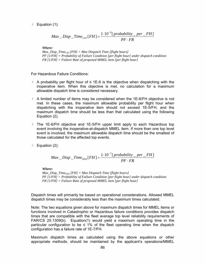
86
Equation (1):
FRPF
FHperyprobabilitFHTimeDispMax CAT
]__[101][__9
Where: Max_Disp_TimeCAT [FH] = Max Dispatch Time [flight hours] PF [1/FH] = Probability of Failure Condition [per flight hour] under dispatch condition FR [1/FH] = Failure Rate of proposed MMEL item [per flight hour]
For Hazardous Failure Conditions:
A probability per flight hour of ≤ 1E-6 is the objective when dispatching with the inoperative item. When this objective is met, no calculation for a maximum allowable dispatch time is considered necessary.
A limited number of items may be considered when the 1E-6/FH objective is not met. In these cases, the maximum allowable probability per flight hour when dispatching with the inoperative item should not exceed 1E-5/FH, and the maximum dispatch time should be less than that calculated using the following Equation (2).
The 1E-6/FH objective and 1E-5/FH upper limit apply to each Hazardous top event involving the inoperative-at-dispatch MMEL item. If more than one top level event is involved, the maximum allowable dispatch time should be the smallest of those calculated for the affected top events.
Equation (2):
FRPF
FHperyprobabilitFHTimeDispMax HAZ
]__[101][__7
Where: Max_Disp_TimeHAZ [FH] = Max Dispatch Time [flight hours] PF [1/FH] = Probability of Failure Condition [per flight hour] under dispatch condition FR [1/FH] = Failure Rate of proposed MMEL item [per flight hour]
Dispatch times will primarily be based on operational considerations. Allowed MMEL dispatch times may be considerably less than the maximum times calculated.
Note: The two equations given above for maximum dispatch times for MMEL items or functions involved in Catastrophic or Hazardous failure conditions provides dispatch times that are compatible with the fleet average top level reliability requirements of FAR/CS 25.1309(b). Equation(1) would yield a maximum operating time in the particular configuration to be ≤ 1% of the fleet operating time when the dispatch configuration has a failure rate of 1E-7/FH.
Maximum dispatch times as calculated using the above equations or other appropriate methods, should be maintained by the applicant’s operations/MMEL

87
group. That group will work with the Flight Operations Evaluation Boards (FOEB/OEBs) to decide on an acceptable MMEL entry.
Example Aircraft Level:
When a quantitative analysis is desired to support the qualitative assessment of an MMEL inoperative item dispatch, the following example may be helpful:
a) Use the fault trees for the Catastrophic failure conditions affected by the proposed MMEL item, where that failure condition cannot be mitigated by operational procedures, limitations or a maintenance action prior to dispatch.
b) Review the fault trees to determine whether operation with the inoperative MMEL item (item probability set to 1) leads to a probability per flight hour (at dispatch) of ≤ 1E-8/FH.
If Yes (≤ 1E-8/FH): No numerical analysis needed for maximum allowable dispatch time
If No (> 1E-8/FH): go to c)
c) Calculate the Maximum Dispatch Time using equation Equation(1):
Example numbers:
Probability of Failure (PF) condition per flight hour under Dispatch condition – determined from fault tree with probability of MMEL item to 1:
PF: 3E-8/FH
Failure Rate (FR) of proposed MMEL item per flight hour
FR: 1E-4/FH
Maximum Dispatch Time ≤ (1E-9)/[(3E-8) x (1E-4)]
Maximum Dispatch Time ≤ 333 flight hours
This may result in a 10 day, Category C relief listing in the MMEL.
(B) Changes to Arsenal version of AC 25.1309 / AMC 25.1309 and AC 25.1309-1A:
The following recommended wording changes to the Arsenal version of AC 25.1309 / AMC 25.1309 will allow better coordination and improved clarity between the AC’s / AMC´s recommended certification compliance requirements for FAR/CS 25.1309 and this report's recommendations concerning the MMEL development process. The last
88
paragraph, paragraph 12.d, is also contained in the current AC 25.1309 -1A. The following changes shown in paragraph 12.d are also recommended for the current -1A AC. The advisory circular for FAR/CS 25.1309 should not imply that MMEL configurations be included in the reliability analyses required by that regulation for aircraft certification.
The proposed changes to AC 25.1309 (Arsenal) / AMC 25.1309 paragraph 12.b.(1) and 12.d. are:
b. Maintenance Action. Credit may be taken for correct accomplishment of reasonable maintenance tasks, for both qualitative and quantitative assessments. The maintenance tasks needed to show compliance with FAR/CS 25.1309(b) should be established. In doing this, the following maintenance scenarios can be used:
(1) For failures known to the flight crew see paragraph 12.d.
(2) Latent failures will be identified by a scheduled maintenance task. If this approach is taken, and the Failure Condition is Hazardous or Catastrophic, then a CCMR maintenance task should be established. Some Latent Failures can be assumed to be identified based upon return to service test on the LRU following its removal and repair (component Mean Time Between Failures (MTBF) should be the basis for the check interval time).
c. Candidate Certification Maintenance Requirements.
(1) By detecting the presence of, and thereby limiting the exposure time to significant latent failures that would, in combination with one or more other specific failures or events identified by safety analysis, result in a Hazardous or Catastrophic Failure Condition, periodic maintenance or flight crew checks may be used to help show compliance with FAR/CS 25.1309(b). Where such checks cannot be accepted as basic servicing or airmanship they become CCMRs. AC/AMJ 25.19 details the handling of CCMRs.
(2) Rational methods, which usually involve quantitative analysis, or relevant service experience should be used to determine check intervals. This analysis contains inherent uncertainties as discussed in paragraph 11.e.(3). Where periodic checks become CMRs these uncertainties justify the controlled escalation or exceptional short term extensions to individual CMRs allowed under AC/AMJ 25.19.
d. Flight with Equipment or Functions Known to be Inoperative. An applicant may elect to develop a list of equipment and functions which need not be operative for flight, based on stated compensating precautions that should be taken, e.g., operational or time limitations, flight crew procedures, or ground crew checks. The documents used to show compliance with FAR/CS 25.1309, together with any other relevant information, should be considered in the development of this list. Experienced engineering and operational judgment should be applied during the development of this list. When more than one flight is made with equipment known to be inoperative and that equipment affects the probabilities associated with Hazardous and/or Catastrophic failure conditions, time limits may be needed for the number of flights or allowed operation time in that aircraft configuration. These time

89
limits should be established in accordance with the recommendations contained in FAA Flight Standards Policy.
6.4.3.4 General Comments on Costs and Benefits of the Recommendations
MMEL - Provides a better foundation for potential harmonization between the FOEB and JOEB.
6.4.3.5 Alternatives considered and why they weren’t chosen
None
6.4.3.6 Dissenting Opinions
None
Note: A number of discussions have been tracked in the attached appendix as a record of associated rational.
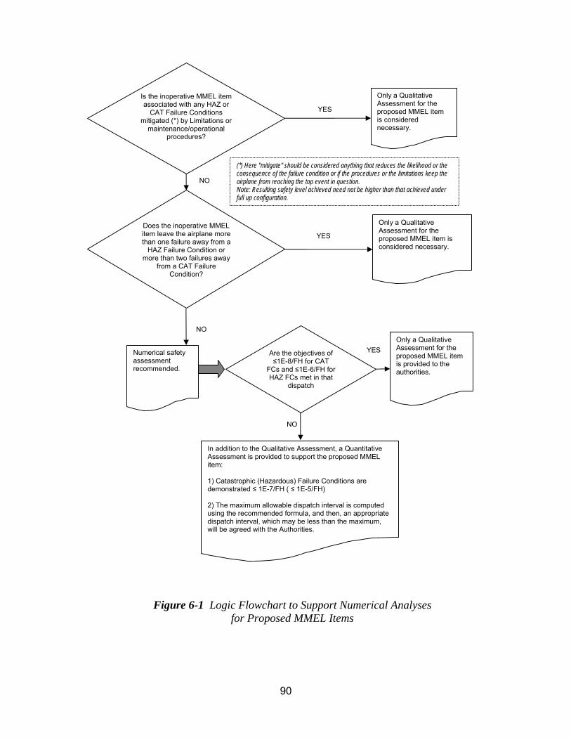
90
Only a Qualitative Assessment for the proposed MMEL item is considered necessary.
Numerical safety assessment recommended.
Is the inoperative MMEL item associated with any HAZ or
CAT Failure Conditions mitigated (*) by Limitations or
maintenance/operational procedures?
NO
Does the inoperative MMEL item leave the airplane more than one failure away from a
HAZ Failure Condition or more than two failures away
from a CAT Failure Condition?
YES
YES
NO
Are the objectives of ≤1E-8/FH for CAT
FCs and ≤1E-6/FH for HAZ FCs met in that
dispatch
YES
Only a Qualitative Assessment for the proposed MMEL item is considered necessary.
Only a Qualitative Assessment for the proposed MMEL item is provided to the authorities.
In addition to the Qualitative Assessment, a Quantitative Assessment is provided to support the proposed MMEL item: 1) Catastrophic (Hazardous) Failure Conditions are demonstrated ≤ 1E-7/FH ( ≤ 1E-5/FH) 2) The maximum allowable dispatch interval is computed using the recommended formula, and then, an appropriate dispatch interval, which may be less than the maximum, will be agreed with the Authorities.
Figure 6-1 Logic Flowchart to Support Numerical Analyses for Proposed MMEL Items
NO
(*) Here "mitigate" should be considered anything that reduces the likelihood or the consequence of the failure condition or if the procedures or the limitations keep the airplane from reaching the top event in question. Note: Resulting safety level achieved need not be higher than that achieved under full up configuration.

91
6.4.4 Flight & Diversion Time Task
In accordance with the ASAWG tasking, the ASAWG assessed the specific risk aspects of Flight Phase, Maximum flight time versus average flight time, and Average diversion time versus maximum allowed diversion time and developed recommendations that:
Clarify section 10 of AC 25.1309 (Arsenal) / AMC 25.1309 for the consideration of intensifying and alleviating factors particularly with respect to flight duration, flight phase, and diversion time.
Clarify section 11 of AC 25.1309 (Arsenal) / AMC 25.1309 for how environmental or operational factors are combined with single failures to address inconsistency that has caused misunderstandings between the regulators and applicants.
Revise Appendix 4 tables of AC 25.1309 (Arsenal) / AMC 25.1309 to clearly focus on environmental conditions and operational factors.
Revise ETOPS AC 1535-1X Chapter 3 Paragraph 16.a (3) and (4) for the use of mission time and diversion times in ETOPS safety analysis.
The following Flight & Diversion Time Task 4 Recommendation gives its benefits, applicability, the recommendation itself with rationales and dissenting opinions.
6.4.4.1 Benefits of the Recommendations
The proposed changes increase safety through elimination of errors in the application of the guidance and by providing applicants and regulators clear guidance that can be applied consistently across systems.
Treat flight time, flight phase and diversion time in the FHA in same manner across applicants and across systems from a single applicant.
Ensure correct hazard classification in FHAs take into account intensifying factors, such that specific risk concerns worthy of being addressed are not overlooked.
Eliminate confusion with respect to the compounding nature of factors in defining the hazard classifications in an FHA.
Eliminate the misunderstandings due to unclear guidance on how environmental or operational factors are combined with single failures.
Appendix 4 tables of AC 25.1309 (Arsenal) / AMC 25.1309 modified to eliminate confusion between failures and environmental conditions and operational factors.
Harmonized use of average long-range flight duration and maximum diversion time for both type 1 and type 2 systems in compliance to the new ETOPS rule (25.1535).
92
6.4.4.2 Applicability of the Recommended Rules/ACs
These changes will apply to new TC or STC and will not be applied retroactively.
6.4.4.3 The Recommendations
6.4.4.3.1 A. Changes to SDAHWG recommended AC 25.1309-Arsenal / AMC 25.1309. Changes are shown in bolded letters.
Add specific risk and specific risk of concern definitions to Section 5 Definitions: “Specific Risk. The risk on a given flight due to a particular condition”.
Rationale: New terms used to define and scope specific risk.
Revise paragraph 10c(2)(ii) to:
(ii) Regardless of the types of assessment used, the classification of Failure Conditions should always be accomplished with consideration of all relevant factors; e.g., system, crew, performance, operational, external. Examples of factors include the nature of the failure modes, any effects or limitations on performance, and any required or likely crew action. It is particularly important to consider factors that would alleviate or intensify the severity of a Failure Condition. Where flight duration, flight phase, or diversion time can adversely affect the FHA outcome, they must be considered as intensifying factors. Other intensifying factors include conditions (not related to the failure, such as weather or adverse operational or environmental conditions), which reduce the ability of the crew to cope with a Failure Condition. An example of an alleviating factor is the continued performance of identical or operationally similar functions by other systems not affected by the Failure Condition. Combinations of factors need only be considered if they are anticipated to occur together.
Rationale: This paragraph was modified to clarify the consideration of intensifying and alleviating factors particularly with respect to flight duration, flight phase, and diversion time. It was recognized by the ASAWG that flight time, flight phase and diversion time have not been treated in the FHA in same manner across applicants and often across systems from a single applicant. While this is not strictly a specific risk concept, it is an imperative that the FHA define the hazard classification for a given failure condition correctly, and without properly accounting for intensifying factors in the FHA, specific risk concerns, worthy of being addressed, may be missed while still in this criteria setting activity.
Specific changes include deleting the second sentence in the paragraph based on the rationale that this sentence does not provide any useful guidance and adds confusion by mixing up relevant factors with effects of failure. A new sentence was added to specifically address flight duration, flight phase and diversion time

93
as relevant factors, and the following sentence was modified slightly to accommodate this sentence and not lose the existing examples of intensifying factors.
The final sentence of the paragraph was added to address confusion with respect to the compounding nature of factors in defining the hazard classifications in an FHA. Obviously, compounding factors that are in and of themselves extremely improbable need not be considered, but the question of what must be considered is a constant source of confusion both with the regulatory specialists and the applicants. The sentence provided seemed to best capture both historical concepts and the concern that the FHA is a qualitative assessment, and therefore to avoid terms that would be interpreted as requiring a probabilistic assessment. Hence the words “Combinations of Factors need only be considered if they are anticipated to occur together”. While it was unavoidable that this still has a certain probabilistic aspect to it (i.e. FAA has already equated "not extremely remote" with "anticipated to occur" via latent failure specific risk provisions such as those used for compliance with FAR25.901(c), FAR25.981(a)(3), etc.) It is the intent of this discussion to make clear that a probabilistic assessment of what to consider as relevant factors is not required, but a qualitative consideration regarding the likelihood of factors and their independence should be part of the assumptions documented with functional failure described in the FHA.
Revise section 11g to:
Operational or Environmental Conditions. A probability of one should usually be used for encountering a discrete condition for which the airplane is designed, such as instrument meteorological conditions or Category III weather operations. However, Appendix 4 contains allowable probabilities which may be assigned to various operational and environmental conditions for use in computing the average probability per flight hour of failure conditions, resulting from multiple independent failures, without further justification. Single failures in combination with operational or environmental conditions leading to catastrophic failure conditions are in general not acceptable. Limited cases that are properly justified, (e.g. operational events or environmental conditions that are extremely remote) may be considered on a case-by-case basis (e.g. operational events or environmental conditions that are extremely remote). (cases that had been accepted in the past are e.g. operational events or environmental conditions that are extremely remote RTO for a cause independent from the failure).
Appendix 4 is provided for guidance and is not intended to be exhaustive or prescriptive. At this time, a number of items have no accepted standard statistical data from which to derive a probability figure. However, these items are included for either future consideration or as items for which the applicant may propose a probability figure supported by statistically valid data or supporting service experience. The applicant may propose additional conditions or different probabilities from those in Appendix 4 provided they are based on statistically valid data or supporting service experience. The applicant should obtain early concurrence of the Certification Authority when such conditions are to be included in an analysis. When combining the probability of such a random condition with

94
that of a system failure(s), care should be taken to ensure that the condition and the system failure(s) are independent of one another, or that any dependencies are properly accounted for.
Rationale: During the ASAWG’s investigation of how single failures are treated for specific risk purposes, the team found that paragraph 11g has unclear guidance for how environmental or operational factors are combined with single failures. The first paragraph above was modified to address this inconsistency within the paragraph that has caused misunderstandings between the regulators and applicants. The contradictory text is in the second sentence where is stated “However, Appendix 4 contains allowable probabilities which may be assigned to various operational and environmental conditions for use in computing the average probability per flight hour of failure conditions resulting from multiple independent failures, without further justification.”; and the last sentence in the third paragraph above which states “When combining the probability of such a random condition with that of a system failure, care should be taken to ensure that the condition and the system failures are independent of one another, or that any dependencies are properly accounted for.” The second sentence of the first paragraph has been modified a new third and forth sentence added to more clearly state when multiple and single failures can combine with the allowable probabilities of Appendix 4. While these inputs are to an average risk calculation method, how operational and environmental conditions are handled whether in average or specific risk calculations is related to the section 10 material above.
Revised Appendix 4 lead paragraph, Environmental Factors and Other Events table:
APPENDIX 4. ALLOWABLE PROBABILITIES.
The following probabilities may be used for environmental conditions and operational factors not due to airplane failure causes in quantitative safety analyses:
Environmental Factors
Condition Model or other Justification Probability
Dispatch into Appendix C Icing 1
Icing outside Appendix C No Accepted Standard data
Probability of specific icing conditions (largest water droplet, temperature etc) within a given flight
No accepted standard data
Head wind >25 kts AC 120-28 10-2 per flight

95
Condition Model or other Justification Probability
during takeoff and landing JAR-AWO
Tail wind >10 kts
during takeoff and landing
AC 120-28
JAR-AWO
10-2 per flight
Cross wind >20 kts
during takeoff and landing
AC 120-28
JAR-AWO
10-2 per flight
Limit design gust and turbulence FAR/JAR 25.341(Under review by Structures Harmonization Working Group)
10-5 per flight hour
Air temperature < -70oC No accepted standard data
Lightning strike No accepted standard data
HIRF conditions No accepted standard data
Other Events
Event Model or other Justification
Probability
Fire in a lavatory not due to airplane failure causes
No accepted standard data
Fire in a cargo compartment not due to airplane failure causes
No accepted standard data
Fire in APU compartment No accepted standard data
Engine fire No accepted standard data
Cabin high altitude requiring passenger oxygen
No accepted standard data

96
Rationale: During the ASAWG’s investigation of single failures as described in 11g rationale above, the team found that Appendix 4 required to be clearly focused on environmental conditions and operational factors. Some of the items listed as “Other Events” in the table in Appendix 4 are system failures, not environmental or operational conditions. These failures were removed from the table and remaining items revised to delineate from system failures. No attempt was made by the team to modify the table for completeness or re-justify the probability values.
Reference to HIRF and Lightning were removed from the table to avoid confusion that numerical analyses are always required for compliance to 25.1309 when effects of HIRF and lightning are considered. coordinate with existing rules changes that control HIRF and Lightning by qualitative means. FAR25.1316 and 25.1317 and their respective ACs (AC 20-158 for HIRF and AC 20-136A for lightning) and guidance material ARP5583 (Guide to Certification of Aircraft in a High Intensity Radiated Field (HIRF) Environment) and ARP5415A (User's Manual for Certification of Aircraft Electrical/Electronic Systems for the indirect Effects of Lightning) document the qualitative means.”
6.4.4.3.2 B. ETOPS (changes to draft AC 1535-1X)
The actual recommendation revising draft AC 1535-1X Chapter 3 Paragraph 16.a (3) and (4):
(3) Airplane system safety assessments for ETOPS are addressed under the specific objectives of FAR25.901(c) and 25.1309, considering the maximum flight time and longest diversion time for which the applicant seeks approval. The ETOPS rule does not modify how ETOPS airplane safety assessments were conducted using the guidelines in AC 120-42A. The main impact that ETOPS will have on airplane system safety assessments is a potentially more severe hazard when considering the long-range and maximum ETOPS diversion distances associated with a maximum ETOPS flight. For example, a failure(s) in an airplane’s environmental control system resulting in either a very hot or very cold cabin temperature could be potentially life-threatening during a five-hour diversion, whereas the same failure would merely be an uncomfortable inconvenience during a 30-minute diversion. What may be considered a minor or major effect during a short diversion may have a hazardous or even catastrophic effect over a longer period. Such time-related effects must be considered in the safety assessments of these types of failures to ensure that any potentially unsafe failure conditions are identified and the proper hazard classification defined. Section K25.1.1 of Appendix K requires the applicant to show that the airplane systems meet the safety objectives of FAR25.901(c) and 25.1309 for any failure condition that has an more severe failure effect when considering a maximum ETOPS diversion following the failure.
(4) Considering the maximum flight time per FAR K25.1.1 does not mean that the numerical probability objectives (for example, on the order of 1E-9/hr for a catastrophic failure condition, on the order of 1E-7/hr for a hazardous failure condition, etc.) for showing compliance with FAR25.1309(b) must be met solely
97
by using the maximum flight time. For ETOPS group 1 significant systems, an applicant may use the “maximum ETOPS mission time” instead. For ETOPS and group 2 significant systems, the probability calculations may be based on average fleet mission time for ETOPS operated aircraft, assuming a maximum diversion time. (Note - not average risk mission time for the whole fleet). The average fleet risk mission time for ETOPS operated aircraft should be estimated based on the applicant’s expectations for how the ETOPS operated aircraft will be used in service. The average fleet risk mission time for ETOPS operated aircraft should include potential ETOPS routes within the maximum range capability of the airplane. This normally results in a longer average flight time than would be used for basic Part 25 certification of non-ETOPS airplanes. For ETOPS group 1 and group 2 significant systems, where a diversion is the probable outcome of a failure condition, e.g. an engine shutdown, a maximum length ETOPS diversion should be assumed in the safety assessment. For example, as discussed in Paragraph (3) above, the cabin thermal environment should consider the maximum diversion time to define the hazard and compliance criteria. For ETOPS group 2 significant systems, the average ETOPS flight time used in numerical probability analyses may be inclusive of all diversion times up to the maximum. The exception for group 2 ETOPS significant systems would be for failure conditions that are diversion time dependent. In those cases, the maximum ETOPS diversion time should be used.
Rationale: Revise group 1 calculation approach from using maximum ETOPS mission time to using the average ETOPS flight duration. Harmonize advisory material to FAA and EASA expectations and pending guidance material.
The use of average fleet risk mission time for ETOPS operated aircraft is proposed to be consistent with the fleet average approach of 25.1309, considering the ETOPS fleet, and IL-20/GAI20X06 Appendix 2 and past EASA practice. This change does not affect system capability, capacity and performance, which should be sized for maximum mission time and maximum diversion time as appropriate.
6.4.4.4 General Comments on Costs and Benefits of the Recommendations
None identified beyond section 6.4.4.1.
6.4.4.5 Alternatives considered and why they weren’t chosen The alternative of not making any of the changes described in section 6.4.4.3 was considered at each step of the review and recommendation development process. In each case, the benefits described in the rationale section for each proposed change outweighed maintaining existing guidance that was not always applied in a consistent manner.
HIRF and Lightning considerations in 25.1309, 25.1316, and 25.1317

98
The ASAWG deliberated exception of HIRF and lightning from 25.1309, but consensus was not achieved due to dissension from all of the certification authorities (ANAC, EASA, FAA, and TCCA.) However, the ASAWG agreed that HIRF and Lightning issues (identified below) should be addressed by a future committee with representation from Systems, Safety, and EME disciplines. The ASAWG concluded this discussion was both outside of the tasking and that the ASAWG did not have adequate representation from the EME community to collectively disposition the subjects listed below. With the exception of removing HIRF and Lightning from the Appendix 4 table for reasons noted above, status quo for H/L considerations should be maintained until that proposed future committee addresses them.
1. Because the failures of HIRF and Lightning protection features are often latent, clear guidance should be provided as to whether qualitative evaluation of failure conditions involving protection features is adequate, and if so, how should such qualitative evaluation be performed. Establish a basis for a qualitative assessment of the architecture to confirm that it is robust and it can withstand such risk.
2. Current practice typically does not include the probabilities of these environmental conditions in safety analyses for initial certification, although the probabilities at times are included in the safety analyses for continued airworthiness determination. If numerical analysis is needed to show compliance, guidance on how this is done should be provided.
3. Instructions for continued airworthiness and its use for HIRF and Lightning Protection features should be clearly explained, particularly if credit is allowed in qualitative and quantitative analyses.
4. AC 20-158 for HIRF and AC 20-136A for lightning, and guidance material ARP5583 (Guide to Certification of Aircraft in a High Intensity Radiated Field (HIRF) Environment) and ARP5415A (User's Manual for Certification of Aircraft Electrical/Electronic Systems for the indirect Effects of Lightning) should be re-evaluated along with AC 25.1309 to establish unambiguous guidelines towards means of compliance to these rules for HIRF and Lightning.
5. Provide explicit guidance for Failure modes and Effects Analyses and Particular Risk Assessments on how to manage HIRF and Lighting protection features if there are any unique requirements.
6. Clear guidance on relationship to HIRF and Lightning Test Levels with respect to common cause aspect of the threat.
7. Ensure that guidance establishes the correct system architecture requirements to protect the airplane when the airplane configuration changes due to various reasons (MMEL, latent failures, corrosion, etc.), as opposed to setting only test levels.
8. There is a need for Lightning assessment under 25.1309 for mechanical systems, in light of ARP 5577 which addresses mechanical systems in a general sense.

99
6.4.4.6 Dissenting Opinions
6.4.4.6.1 Garmin dissenting opinion on changes to AC 25.1309 / AMC 25.1309 paragraph 11g:
To be consistent with the agreed approach to not address HIRF and Lightning in the ASAWG, but rather to maintain the status quo until a new ARAC team can fully address the issues defined, Garmin recommends that the last two sentences of 1st paragraph of 11g be revised from: “Single failures in combination with operational or environmental conditions leading to catastrophic failure conditions are in general not acceptable. Limited cases that are properly justified, (e.g. operational events or environmental conditions that are extremely remote) may be considered on a case-by-case basis (e.g. RTO for a cause independent from the failure).”
To: “Single failures in combination with operational or environmental conditions leading to catastrophic failure conditions are in general not acceptable. Limited cases that are properly justified may be considered on a case-by-case basis.”
The new text may be open enough to leave existing certification practice for HIRF and lightning unchanged until this issue can be resolved. In a separate issue the current AC task 4 report 11g proposal does not provide any other criterion for determining acceptability other than “single failure in combination with operational events or environmental conditions that are extremely remote”. As such in practice it may become the only acceptable criterion even though this may not be appropriate for all situations (e.g. HIRF/L) and is not the intent of the ASAWG. I have been concerned that there is the potential that existing AC numerical reliability and design assurance objectives could be superseded by the new 25.1309 AC/AMC guidance. Specifically when considering operational conditions such as CFIT and entry into stall that are not extremely remote (< 1E-7/FH).
The example criterion is more conservative than other existing AC/AMC system guidance. For example TAWS and stick pusher availability is 1E-4 and level C. No single failure implies multiple redundancy and level A software for loss of function. By removing the example criteria this concern is diminished and may allow me to recommend that the current Garmin recommendation to change the current criteria (see Garmin dissent) to the one below, be withdrawn.
DISSENT EXAMPLE: If the crew were to perform an abort and there was a throttle jam (after power set), the asymmetric thrust (on wing mounted engines) - because of one stuck throttle - will cause the aircraft to laterally depart the runway. For the purpose of the example this is assumed to be a potential catastrophic failure condition. The probability of a throttle jam was/is on-the-order-of 1E-7/FH. The exposure period for the jam - after power set and before V1 - is approximately 20 seconds. The probability of a jam is 1E-7*(20/3600) = 5.5E-10. The probability of an abort due to an external event is about 1 in 2000 takeoffs. This is not extremely remote per the new AC guidance. The applicant cannot combine the "jam probability" with the "probability of an abort". Therefore the applicant does not meet the new “no single failure” criterion proposed by the ASAWG AC/AMC 25.1309 guidance.

100
ASAWG disposition of Garmin Dissenting opinion - ASAWG reviewed Garmin’s dissenting opinion above and recommended change to the wording of 11g. The ASAWG has agreed to remove the parenthetical “e.g. RTO for a cause independent from the failure” and the revised 11g is shown in 6.4.4.3.1 above. However, the ASAWG disagrees with the removal of the parenthetical “e.g. operational events or environmental conditions that are extremely remote”. It was felt that the example “operational or environmental conditions that are extremely remote”, offered an example for cases where one or more operational or environmental condition could be stacked up to represent an unrealistic failure condition. This is not intended to prevent other arguments such as the obscurity of the failure mode, but to provide one example of an acceptable criterion.
6.4.4.6.2 Garmin dissenting opinions on HIRF and Lightning considerations in 25.1309, 25.1316, and 25.1307:
Garmin provided dissenting opinions on the HIRF and Lightning considerations in 25.1309, 25.1316, and 25.1307 (see chapter 6.4.4.5 “Alternatives considered and why they weren’t chosen”). Garmin Dissenting opinion (1): Section 6.4.4.5 bullet 2: Dissent: “The term safety analysis is too broad when related to probability of one assumption. Typically for EME a probability of 1 is limited to common cause analyses. Bullet 2 should also be clarified that numerical analysis is in relation to probabilistic criteria.” Recommendation: Current practice typically does not include the probabilities of these environmental conditions in common cause analyses for initial certification, although the probabilities at times are included in the safety analyses for continued airworthiness determination. If numerical analysis is needed to show compliance to probabilistic criteria, guidance on how this is done should be provided. ASAWG disposition of Garmin Dissenting opinion (1): ASAWG did not intend to imply that a probability of 1 should be used for analysis other than common cause analyses. The ASAWG does not believe this is conveyed by the sentence in bullet 2. Garmin Dissenting opinion (2): Section 6.4.4.5 bullet 5: Dissent: It is not clear what this is asking for in relation to unique requirements. How can the new group provide FMEA & PRA guidance for undefined requirements? What is meant by the word “manage”? Testing ensures that there is no failure that can affect the full up airplane so what is the purpose of FMEA? ASAWG disposition of Garmin Dissenting opinion (2): Though it could perhaps be worded better, the intent of this bullet was to ensure that if the future committee identifies any unique requirements on how to treat HIRF and Lightning in FMEAs and PRAs, then the future committee should also provide guidance that is explicit for FMEAs and PRAs. Therefore no change is recommended to proposal at this time.

101
Garmin Dissenting opinion (3): Section 6.4.4.5 bullet 5: Dissent: This is already done today by the guidance provided in the HIRF/Lightning AC. Recommendation: This bullet should be removed or otherwise clarify more specifically the concern. ASAWG disposition of Garmin Dissenting opinion (3): It was not clear to the ASAWG when reviewing the AC guidance that the test levels adequately addressed multiple units providing redundancy for a specific function. This was the intent of bullet 6. If the future committee concurs with the dissenting opinion that the existing guidance adequately addresses this issue, then recommendation can be ignored. Garmin Dissenting opinion (4): Section 6.4.4.5 bullet 7: Dissent: The text of bullet 7 implies the current practice is unacceptable. The language should be more neutral. It is the new committee responsibility to determine what is acceptable. Recommendation: The review should consider whether the current guidance/practice establishes adequate system architecture requirements to protect the airplane when the airplane configuration changes due to various reasons (MMEL, latent failures, corrosion, etc.). ASAWG disposition of Garmin Dissenting opinion (4): ASAWG disagrees that the Bullet 7 implies that the current practice is unacceptable. The intent was to identify the various aspects that the future committee should consider. Garmin Dissenting opinion (5): Section 6.4.4.6.1 Dissenting opinion Dissent: The ASAWG disposition of the Garmin dissent does not address the first paragraph of the existing dissent (reference section 6.4.4.6.1, page 88). Further, Garmin wishes to modify its existing dissent to include the following paragraph. This paragraph will expand and clarify an existing point being made by Garmin, by the current text, which was not fully understood. Recommendation: “The example [i.e. operational events or environmental conditions that are extremely remote] in paragraph 11g generated discussions with the ASAWG on its potential impact for HIRF/Lightning design and testing. It was recommended by the ASAWG that there should be a subsequent committee to address these issues raised as documented in section 6.4.4.5 of the report. However given that the AC 25.1309 may be released prior to the formation of committee or even regulatory acceptance of the recommendation it seems premature to adopt this example in the AC that could result in additional costs to applicant if interpreted to apply to HIRF and Lightning. These cost aspects have yet to be determined by the ASAWG. For example, the interpretation of this criterion could result in the demonstration by test of multiple level A paths to mitigate HIRF and lightning effects. ” ASAWG disposition of Garmin Dissenting opinion (5):

102
Report is clearly states that "With the exception of removing HIRF and Lightning from the Appendix 4 table for reasons noted above, status quo for H/L considerations should be maintained until that proposed future committee addresses them."

103
Appendix A
6.4.5 Appendix to Latent Failure Task
6.4.5.1 Large Aircraft Cost Worksheets
C:\Safety\TAEIG WG\Final Report\Latent\A
C:\Safety\TAEIG WG\Final Report\Latent\A
C:\Safety\TAEIG WG\Final Report\Latent\A
6.4.5.2 Large Business Aircraft Cost Worksheets
C:\Safety\TAEIG WG\Final Report\Latent\A
C:\Safety\TAEIG WG\Final Report\Latent\A
6.4.5.3 Cessna Cost Worksheets
C:\Safety\TAEIG WG\Final Report\Latent\A

104
6.4.5.4 Example of FAR/CS 25.1309(b)(4)
The following example illustrate how the quantitative criteria of FAR/CS 25.1309 (b)(4) is to be implemented. The methodology used is based on the identification of the minimal cut sets associated with the top event of the generic system level fault tree provided in Figure 7-1.
The term minimal cut set refers to the smallest set of components whose failure is sufficient to cause system failure or in this case the failure condition of concern. The list of cut sets should be produced by cut set order. This will group all dual order cut sets or failure combinations. The list of dual order cut sets should then be reduced further based on the probability of each cut sets. Dual failures whose probability is less than 1E-12/FH need not be considered for further analysis. The entire list of cut sets of the fault tree in Figure 7-1 are provided in Table 7-1.
The cut sets that contain a basic event that is latent for more than one flight are then identified from the list in Table 7-1. The probability of each of these latent events should be less than 1E-3. Then group those dual order cut sets that contain the same latent basic event. For each group assume that latent basic event has failed and sum the remaining active failure probabilities. For each group the sum of the active failures should be less than 1E-5/FH. An alternative but more conservative method would be to rerun the fault tree probability calculation assuming for each model rerun that a different latent basic event had failed.
The result of the limit latency analysis is provided in Table 7-1. Events L002, L003, L004 and L005 comply with the requirements of FAR/CS 25.1309(b)(4)(ii), Latent event L001 is not in compliance.
The result of the residual risk analysis is also provided in Table 7-1. Cutsets #1, #2 and #5 comply with the requirements of FAR/CS 25.1309(b)(4)(i), Cutset #3 fails to comply due to active event A002.

105
TOP
TOP
9 . 9 8 E- 10
GAT E 1
G0 0 1
4 . 7 2 E- 10
LAT 1
L0 0 1
p=4 . 5 0 E- 0 3 10 0 0 H 9 . 0 0 E- 0 6 / H
GAT E 5
G0 0 5
1. 0 5 E- 0 7
ACT 1
A0 0 1
p=1. 0 0 E- 0 7 1. 0 0 H 1. 0 0 E- 0 7 / H
GAT E 7
G0 0 7
5 . 0 0 E- 0 9
ACT 2
A0 0 2
p=2 . 0 0 E- 0 5 1. 0 0 H 2 . 0 0 E- 0 5 / H
LAT 2
L0 0 2
p=2 . 5 0 E- 0 4 10 0 H 5 . 0 0 E- 0 6 / H
GAT E 2
G0 0 2
2 . 0 0 E- 10
ACT 2
A0 0 2
p=2 . 0 0 E- 0 5 1. 0 0 H 2 . 0 0 E- 0 5 / H
LAT 3
L0 0 3
p=1. 0 0 E- 0 5 10 . 0 0 H 2 . 0 0 E- 0 6 / H
GAT E 3
G0 0 3
3 . 2 5 E- 10
ACT 3
A0 0 3
p=6 . 5 0 E- 0 7 1. 0 0 H 6 . 5 0 E- 0 7 / H
LAT 4
L0 0 4
p=5 . 0 0 E- 0 4 5 0 0 H 2 . 0 0 E- 0 6 / H
GAT E 4
G0 0 4
5 . 0 0 E- 13
ACT 4
A0 0 4
p=1. 0 0 E- 0 6 1. 0 0 H 1. 0 0 E- 0 6 / H
LAT 5
L0 0 5
p=5 . 0 0 E- 0 7 10 . 0 0 H 1. 0 0 E- 0 7
Figure 7-1: Example of FAR/CS 25.1309(b)(4) Fault Tree

106
TOP Event = 9.98E-10/FH
# Inputs Description Rate
(per hour) Exposure
(hour) Event Prob Probability Application of 25.1309(b)(4)
A001 ACT 1 1.0E-7 1 1.0E-7 1
L001 LAT 1 9.0E-6 1000 4.5E-3 4.50E-10
It does NOT meet the limit latency criterion since L001 is higher than 1E-3.
A003 ACT 3 6.5E-7 1 6.5E-7 2
L004 LAT 4 2.0E-6 500 5.0E-4 3.25E-10
It does meet both residual risk and limit latency criteria.
A002 ACT 2 2.0E-5 1 2.0E-5 3
L003 LAT 3 2.0E-6 10 1.0E-5 2.00E-10
It does NOT meet the residual risk criterion since A002 is higher than 1E-5/FH.
A002 ACT 2 2.0E-5 1 2.0E-5
L001 LAT 1 9.0E-6 1000 4.5E-3 4
L002 LAT 2 5.0E-6 100 2.5E-4
2.25E-11
Although L001 is higher than 1E-3 and A002 is higher than 1E-5/FH, this is NOT applied since is more than dual failure combination. Note: L001 is the same failure that contributes in failure combination #1.
A004 ACT 4 1.0E-6 1 1.0E-6 5
L005 LAT 5 1.0E-7 10 5.0E-7 5.00E-13
Although It does meet both residual risk and limit latency criteria, this is NOT applied to this failure combination since it is lower than 1E-12/FH.
Flight Time = considering 1 hour of flight.
2][ TFR
xLatP
Table 7-1: Example of FAR/CS 25.1309(b)(4) Minimal Cut Set

Specific Risk_________________________________________________________107
ARAC ASAWG Report April 2010 Rev 5.0
6.4.5.5 Comments to chapter 6.4.1
The following comments to chapter 6.4.1 were provided. These general comments should be reviewed when preparing the final NRPM.
Comments from ANAC:
Comments from ANAC to Final ASAWG
Comments from the FAA:
Comments from FAA to Final ASAWG Repo
Note: The dissenting opinion #1 and #2 and the significant comment #1 and #2 in the above attached file are reviewed in detail in chapter 6.4.1.6 “Dissenting Opinion and Discussion” of this report.
Comments from the Boeing:
Boeing agrees with the recommendation of the ASAWG, however, we request that it be noted in the report that our acceptance is contingent on the entire set of recommendations being followed. Selecting particular items out of the recommendation (like implementing the latent rule and guidance changes in 25.1309 without changing the associated specific risk regulations (25.671, 25.933, etc.)) will cause Boeing to re-evaluate the costs and benefits of this change.
Boeing also requests that it be documented that applicability is clear, the rule and guidance are not applied retroactively; i.e. Change Product Rule 14 CFR 21.101 applies.
Finally, Boeing wants to ensure that it is clear that the failure condition considered in the new latency rule is not the result of a single failure and an environmental or operational condition (covered by paragraph 11g of AC 25.1309 proposal) and recommends additional discussion of this in the preamble to the rule.
Comments from Garmin:

Specific Risk_________________________________________________________108
ARAC ASAWG Report April 2010 Rev 5.0
Comment (1): Section 6.4.1, 3rd paragraph: Comment: This sentence is incomplete. What happens if these changes are not implemented is not conveyed by the sentence. Recommendation: This sentence should convey that without these changes the benefits of section 6.1.4.1 are not met. Comment (2): Section 6.4.1 8th paragraph: Comment: The introductory words to this sentence can be stated more clearly. Recommendation: Change “The limitations to include this criteria…” to “The decision to limit this criteria…” Comment (3): Section 6.4.1 9th paragraph: Comment: The phrase statistical fall out does not seem to be accurate. The applicable AC text refers to adequate design margin. Recommendation: Finally, the 1E-12 limit criterion was established following a review by different companies on the impact of the specific risk criteria. This impact included an evaluation of analytical workload versus benefit. Comment: Given the location of this 1E-12 limit in the AC 9.b.(6) it should be made clear that the review of latent failures for multiple latent failure combinations is qualitative. Recommendation: “Further when considering multiple latent failures the 1E-12 limit should be considered to define the scope of the qualitative evaluation to avoid latency. Typically such a review would not need to address quadruple redundancy or dual active – monitor designs etc.” Comment (4): Section 6.4.1.1.2 Change AC/AMC 25.629-1A, Section (c)(3)(c): Comment: Previously the first sentence stated “However, the ASAWG decided not to consider adding a specific sentence to address active – active failure combinations.” This was a lead in to the next sentence. For example the second sentence refers to “redundancy in these situations”. However what situations are being referred to is no longer clear from the modified first sentence. Recommendation: Add the word “other” to the first sentence. “However, the ASAWG decided not to consider other changes to FAR/CS 25.629…”

Specific Risk_________________________________________________________109
ARAC ASAWG Report April 2010 Rev 5.0
Comment (5):
Section 6.4.1.1.1 Add to Arsenal Draft of AC/AMC 25.1309, Section 9.b.(6):
Section 9.b.(6) of the proposed AC can be interpreted to be more severe than the quantitative requirements of the regulation. As written, even if the applicant’s design is triple redundant or better (e.g. 2 latents plus an active), it may still not be viewed as sufficient even though all aspects of the rule had been satisfied. What is sufficient seems to be is subjective and unbounded other than the E-12 statement. During the final stages of the design substantiation the regulatory authorities could review the SSA and in theory could request additional redundancy. Since adequacy is subjective and unbounded, the application may differ from ACO to ACO. This falls short of the committee objective to standardize the treatment of specific risk management.
Recommendation: It is recommended that the 25.1309 (b) (4) rule or AC 25.1309 guidance be revised to limit the addition of redundancy to dual failure conditions where a latent failure is present for more than one flight. This is still consistent with the guidance for 25.629 and 25.933. Given that CFR 25.629, 25.933 and 25.981 together addresses no more than three catastrophic failure conditions out of the total that has to be evaluated by all rules such as 25.671 and 25.1309, this recommendation does not deviate from the ASAWG objective of adopting a consistent certification standard. The quantitative requirements of 25.981 were not considered warranted by the ASAWG when compared to current evaluation performed for the majority of critical systems.
Comment from Airbus: Consistency between AC/AMC 25.629 and FAR/CS 25.671 (c)(2) : - AC/AMC 25.629 proposal : “Any damage or failure conditions considered under
FAR25.571, FAR25.631 and FAR25.671. The actuation system minimum requirements should also be continuously met after any combination of failures not shown to be extremely improbable (occurrence less than 1E-09 per flight hour). However, certain combinations of failures, such as d Loss of dual electric system or dual hydraulic systems are not normally considered extremely improbable.
- FAR/CS 25.671 (c)(2) proposal : Any combination of failures not shown to be extremely improbable. Furthermore, the flight controls must comply with FAR25.1309(b)(4). This paragraph excludes failures of the type defined in (c)(3). , excluding jamming (for example, dual electrical or hydraulic system failures, or any single failure in combination with any probable hydraulic or electrical failure).
On FAR25.671 proposal, examples of combination of failures non Extremely Improbable were removed whereas the same examples are kept in AC/AMC 25.629. What is the rational ? Why not to refer to FAR25.1309(b)(4) in both texts as follows : - “Any damage or failure conditions considered under FAR25.571, FAR25.631 and
FAR25.671. The actuation system minimum requirements should also be continuously

Specific Risk_________________________________________________________110
ARAC ASAWG Report April 2010 Rev 5.0
met after any combination of failures not shown to be extremely improbable (occurrence less than 1E-09 per flight hour). However, certain combinations of failures, such as d Loss of dual electric system or dual hydraulic systems are not normally considered extremely improbable. and under condition of FAR25.1309(b)(4).
6.4.6 Appendix to Aging & Wear Task
None
6.4.7 Appendix to MMEL Task
6.4.7.1 MMEL Recommendation
The following provides discussions following the Cedar Rapids meeting where resolutions have been found but it was considered to be of value that these discussions be recorded.
Those discussions lead to tweak some wording in order to clarify the intent and get a consensus on the attached flowchart. Those discussions and agreement have been tracked through the issuance of an interim final report dated July 17, 2009.
In parallel, the same day , TCCA expressed mainly a concern on the use in the MMEL process of mitigation factors to alleviate and further proposed a change to the first box of the flowchart
Dassault Aviation requested clarifications on the proposed change to the flowchart. Following discussions with EASA and TCCA, Dassault Aviation was satisfied by their answers and cleared the proposed text (Extract from Dassault mail dated August 21 and 25, 2009).
Extract from Dassault Aviation mai
During the meeting in March2010, consensus was reached between members to modify the body of the report based on Boeings latest proposal.
Boeing mail extract 06 Feb 10.doc
Specific Risk_________________________________________________________111
ARAC ASAWG Report April 2010 Rev 5.0
6.4.8 Appendix to Flight & Diversion Time Task
The following comments to chapter 6.4.4 were provided by Garmin. These general comments should be reviewed when preparing the final NRPM.
Comment (1):
Section 6.4.4.3 The Recommendations:
Comment: The terms specific risk and specific risk of concern are not used in the AC 25.1309.
Recommendation: Delete definitions.
Comment (2):
Section 6.4.1.6:
Comment: Can it be better clarified how the residual risk criterion is to be addressed. Perhaps include an example. It seems that the ASAWG is stating that the failure of the good engine (one without the pre-existing fault) cannot result in a condition that would cause the other engine fault to propagate to a failure (loss of engine or reduced thrust in icing conditions, WAT operations) that would be catastrophic. Similarly if engine with pre-existing fault encounters a condition that causes reduced thrust or engine failure prior to the good engine failure then is it assumed that the time between the first engine failure and landing the airplane can be applied as the exposure time to the good engine such that it will meet the residual risk?
EXCOM Update For TAEIG
April 14, 2010
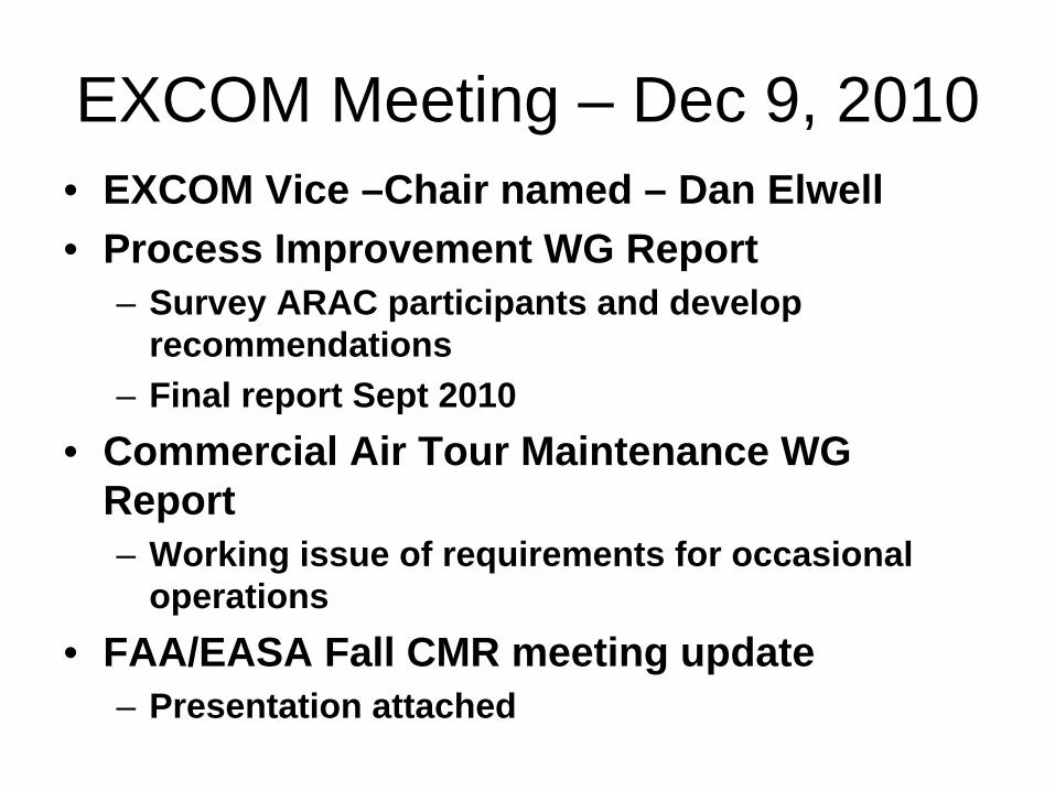
EXCOM Meeting – Dec 9, 2010• EXCOM Vice –Chair named – Dan Elwell• Process Improvement WG Report
– Survey ARAC participants and develop recommendations
– Final report Sept 2010• Commercial Air Tour Maintenance WG
Report– Working issue of requirements for occasional
operations • FAA/EASA Fall CMR meeting update
– Presentation attached

EASA/FAA/TCCA Progress Update on
Rulemaking Cooperation

2009 Progress – Meetings
July 2009 (Ottawa – working group meeting):
• Acknowledged importance to meet the building expectations from industry and to keep the momentum going.
• TCCA announced that, as of June 22nd, flight standards rulemaking projects would be included in this cooperation effort.
• Developed means for improving communication.

2009 Progress – Meetings
July 2009 (Ottawa – working group meeting):• Continued to identify new areas of
common interest for 2010 and beyond, using the authorities respective rulemaking inventories.
• Developed common rulemaking inventory containing tasks of joint interest.
• Agreed on structure and content for online collaborative platform.

2009 Progress – Meetings
October 2009 (Washington DC– Certification, Maintenance, and Rulemaking meeting):• Agreed to explore the possibility for
inclusion of air traffic and airport rulemakings in cooperation effort.
• Acknowledged the importance of including guidance material (ACs) in cooperation discussions.
• Discussed significant changes in direction and joint involvement in disposition of comments.

7 Test Cases• Case #1 – Protection From Debris• Case #2 – Flight Crew Alerting• Case #3 – Widespread Fatigue Damage• Case #4 – Certification of Turbojets• Case #5 – Damage Tolerance
Evaluation of Metallic Rotorcraft Structures
• Case #6 – Part 129 Operations Specifications
• Case #7 – Safety Management System

7 Test Cases – Lessons Learned• Although focal points are communicating,
we need to improve communication tools and expand existing collaborative platform.
• Need to monitor process to ensure that progress is being made and goals of cooperation effort are being met.
• Focal points need a better understanding of their roles and responsibilities.

Next Steps• Want to expand beyond test case
scenarios to include additional rulemakings of common interest.
• Continue to institutionalize use of online communication tool.
• Launch formal training for focal points.• Continue to improve monitoring of
process.

TCCA Report
TAEIG April 14th 2010

CAR 521 is Now Law
• Came in to effect Dec 01, 2009• Car 521 replaces 16 regulations with 1
– Removal of CAR 511, 513, 516, 522, 523, 525, 527, 59, 531, 533, 535, 537, 541, 551, 591, 593
• Removal of 4 standards– AWM Chapter 511 – Approval of the Type Design of an Aeronautical
Product– AWM Chapter 513 - Approval of Modification and Repair Designs– Standard 591 - Service Difficulty Reporting– Standard 593 – Airworthiness Directives

C-Series
• Bombardier filed an application Dec 10th 2009• Will be certified under CAR 521• Concurrent Validation with FAA and EASA
– Initial Type Board Meeting May 26-27 • Invitation for EASA and FAA
• Of interest:– Will use Pratt and Whitney Geared Turbo Fan– Extensive use of Composites– Fly by wire– Integrated Modular Avionics

AAWG Report to TAEIGAAWG Report to TAEIG April 14, 2010April 14, 2010
Dr. Rao VaranasiDr. Rao VaranasiCo ChairCo Chair
Airworthiness Assurance Airworthiness Assurance Working Group (AAWG)Working Group (AAWG)
April 14, 2010April 14, 2010 AAWG Report to the TAEIGAAWG Report to the TAEIG 22
Airworthiness Assurance Airworthiness Assurance Working GroupWorking Group•• MembershipMembership•• MeetingsMeetings•• Current TaskCurrent Task•• StatusStatus

April 14, 2010April 14, 2010 AAWG Report to the TAEIGAAWG Report to the TAEIG 33
AAWG Membership: AAWG Membership: No changesNo changesName Company AAWG Member E-mail Address
Rao Varanasi Boeing Yes (Co-Chair) [email protected]
Roger Skinner Boeing No [email protected]
Andreas Behrmann Airbus Yes [email protected]
Ralph Sykes LMCO Yes [email protected]
Mark Yerger FedEx Yes (Co-Chair) [email protected]
Phil Ashwell British Airways Yes [email protected]
Joe Moses Continental Airlines Yes [email protected]
Greg Pattison Northwest Airlines Yes [email protected]
Ed Walton UPS Yes [email protected]
Harry Demarest American Airlines Yes [email protected]
Jon Oberdick US Airways Yes [email protected]
Larry Williams United Airlines Yes [email protected]
Jun Yamanaka
Shinichi Yoshizaki
Japan Airlines
ANA
No
No
Joe Freese ABX Air Yes [email protected]
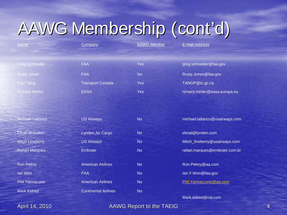
April 14, 2010April 14, 2010 AAWG Report to the TAEIGAAWG Report to the TAEIG 44
AAWG Membership (contAAWG Membership (cont’’d)d)Name Company AAWG Member E-mail Address
Greg Schneider FAA Yes [email protected]
Rusty Jones FAA No [email protected]
Paul Tang Transport Canada Yes [email protected]
Richard Mintor EASA Yes [email protected]
Michael Tallarico US Airways No [email protected]
Ethan Brandon Lynden Air Cargo No [email protected]
Mitch Lineberry US Airways No [email protected]
Rafael Marques Embraer No [email protected]
Ron Pekny American Airlines No [email protected]
Ian Won FAA No [email protected]
Phil Yannacone American Airlines No [email protected]
Mark Eldred Continental Airlines [email protected]
April 14, 2010April 14, 2010 AAWG Report to the TAEIGAAWG Report to the TAEIG 55
MeetingsMeetings
•• There was one meeting of the AAWG on February 10There was one meeting of the AAWG on February 10-- 11, 2010 since the last TAEIG meeting in September 11, 2010 since the last TAEIG meeting in September 23, 200923, 2009
•• The next AAWG meeting is tentatively scheduled in The next AAWG meeting is tentatively scheduled in June 2010 at a venue TBD June 2010 at a venue TBD

April 14, 2010April 14, 2010 AAWG Report to the TAEIGAAWG Report to the TAEIG 66
Current TasksCurrent Tasks•• AASFR Task:AASFR Task:
–– Tasked Tasked -- May 13, 2004;May 13, 2004;–– Status Status -- In work and on schedule;In work and on schedule;–– Two Phases:Two Phases:
•• Phase 1 is complete as of April 2007Phase 1 is complete as of April 2007•• Scheduled Completion for Phase 2 is December Scheduled Completion for Phase 2 is December
20092009-- Task 4Task 4–– Development of model specific programsDevelopment of model specific programs–– AAWG to provide oversight function and guidance for AAWG to provide oversight function and guidance for
some STG technical issuessome STG technical issues
..

April 14, 2010April 14, 2010 AAWG Report to the TAEIGAAWG Report to the TAEIG 77
Task 4Task 4 AAWG DiscussionsAAWG Discussions•• Operator Implementation Plan (OIP) Using TCH Operator Implementation Plan (OIP) Using TCH
Compliance DocumentsCompliance Documents•• Operator concerns, views and suggestions on TCH Operator concerns, views and suggestions on TCH
Compliance DocumentsCompliance Documents•• Part 26 Rule Situation for AD Affected StructurePart 26 Rule Situation for AD Affected Structure•• Part 26 Rule Requirements for Production ChangesPart 26 Rule Requirements for Production Changes•• Part 26 Subpart E compliance resulted in a program Part 26 Subpart E compliance resulted in a program
requiring far more resources than the earlier estimates requiring far more resources than the earlier estimates due to conservative interpretations by the FAA and the due to conservative interpretations by the FAA and the DAH. If the operators also implement conservative DAH. If the operators also implement conservative interpretations in their compliance to the Aging Airplane interpretations in their compliance to the Aging Airplane Safety Final (Operational) Rule, there will be severe Safety Final (Operational) Rule, there will be severe resource concerns and industrial capacity concerns resource concerns and industrial capacity concerns

April 14, 2010April 14, 2010 AAWG Report to the TAEIGAAWG Report to the TAEIG 88
Rule Issues Requiring TAEIG HelpRule Issues Requiring TAEIG Help
•• Sufficient guidance and training to PMI for Sufficient guidance and training to PMI for timely approval of individual operator timely approval of individual operator OIPsOIPs
•• Eliminate the need for duplicate approvals for Eliminate the need for duplicate approvals for Part 26 and AD affected structurePart 26 and AD affected structure–– Provide FAA Guidance that Part 26 approvals serve as Provide FAA Guidance that Part 26 approvals serve as
approvals for all AD affected structure where the AD approvals for all AD affected structure where the AD required actions are based on Damage Tolerance required actions are based on Damage Tolerance (same as the Part 26 Rule requirement) (same as the Part 26 Rule requirement)
•• NonNon--harmonized elements of FAA/EASA Aging harmonized elements of FAA/EASA Aging Airplane Rules, remain as a concern to Airplane Rules, remain as a concern to DAHsDAHs and Operatorsand Operators

Questions?Questions?
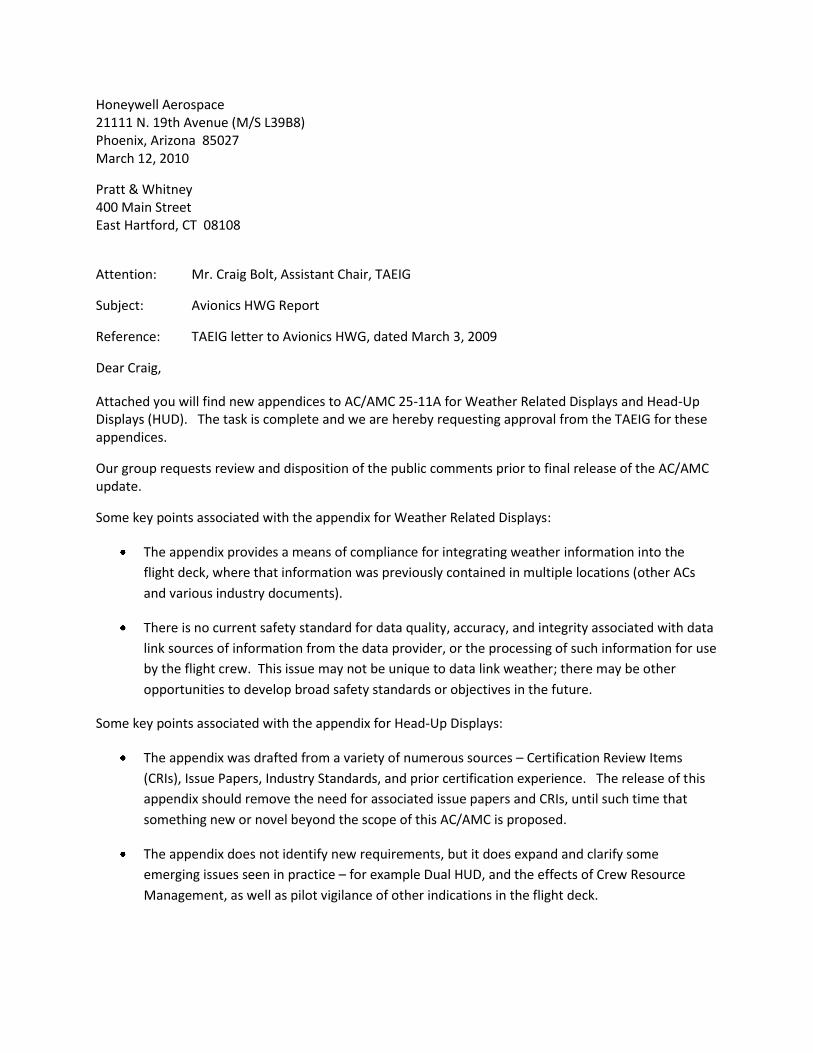
Honeywell Aerospace 21111 N. 19th Avenue (M/S L39B8) Phoenix, Arizona 85027 March 12, 2010
Pratt & Whitney 400 Main Street East Hartford, CT 08108
Attention: Mr. Craig Bolt, Assistant Chair, TAEIG
Subject: Avionics HWG Report
Reference: TAEIG letter to Avionics HWG, dated March 3, 2009
Dear Craig,
Attached you will find new appendices to AC/AMC 25-11A for Weather Related Displays and Head-Up Displays (HUD). The task is complete and we are hereby requesting approval from the TAEIG for these appendices.
Our group requests review and disposition of the public comments prior to final release of the AC/AMC update.
Some key points associated with the appendix for Weather Related Displays:
The appendix provides a means of compliance for integrating weather information into the
flight deck, where that information was previously contained in multiple locations (other ACs
and various industry documents).
There is no current safety standard for data quality, accuracy, and integrity associated with data
link sources of information from the data provider, or the processing of such information for use
by the flight crew. This issue may not be unique to data link weather; there may be other
opportunities to develop broad safety standards or objectives in the future.
Some key points associated with the appendix for Head-Up Displays:
The appendix was drafted from a variety of numerous sources – Certification Review Items
(CRIs), Issue Papers, Industry Standards, and prior certification experience. The release of this
appendix should remove the need for associated issue papers and CRIs, until such time that
something new or novel beyond the scope of this AC/AMC is proposed.
The appendix does not identify new requirements, but it does expand and clarify some
emerging issues seen in practice – for example Dual HUD, and the effects of Crew Resource
Management, as well as pilot vigilance of other indications in the flight deck.

The material in the appendix is consistent with relevant guidance contained in the new draft of
AC/AMC 25-1309, the new draft of AC/AMC 25-1322, and AC/AMC 25-1329.
Other recommendations and notes:
Our group still offers the assistance to review the draft 20-series AC on SVS and EVS, to help ensure consistency and potential impact to AC/AMC 25-11A. Please let us know how we can help.
Certification airworthiness standards for weather may be helpful long term. For example the safety
objectives cited in this AC are based on history and practice – but there are no airworthiness standards.
The introduction of and dependence on weather awareness products in the “Next Gen” environment
may result in a higher dependence of the weather information being presented to the pilots. To help
drive the need for future airworthiness standards, we recommend collaboration between Avionics and
Weather experts to address key issues, and future trends, to identify top level safety objectives for the
long term.
AC 25-11A and future versions were intended to be used in conjunction with new draft rules 25.1322
and 25.1302. The quick release of these items is recommended.
The group again discussed whether a rule for electronic displays would provide a better integrated
approach to the basic requirements of flight deck display systems. While AC 25-11A does a good job of
reconciling current (multiple and related) rules, many of the rules were predicated on electromechanical
instruments, and do not consider a holistic view of the flight deck.
Based on our continued work in developing guidance for display systems, and considering the
airworthiness impact to the “Next Gen” environment, our group endorses a future task to study new
rulemaking for modern flight deck displays.
The draft HUD Appendix provides guidance for recording specific HUD operational parameters, which
could have implications on flight data recorder and data acquisition changes.
There is no equivalence in Part 27 or Part 29 for this type of guidance material. We recognize that our
task is specific to Part 25 applications, but we recommend that the latest AC/AMC be considered as a
starting point for a future Part 27 / 29 AC. Consistency (between Parts) would help minimize impact to
both industry and regulatory efforts.
While our group plans to continue the task for Airport Surface Guidance Systems and Cockpit Display of
Traffic Information (CDTI), we understand that a new task may be requested (Low-Airspeed Awareness).
We are prepared to work both tasks in a reasonable timeframe.
I would like to thank the group members for all of their dedication to this effort.

Sincerely,
Clark Badie, Chair Avionics HWG
Copy: Mike Kaszycki – FAA-NWR
TAEIG Distribution List
AVHWG Distribution List

1
AC 25-11A Head-Up Display Appendix
1 INTRODUCTION
The material provided in this appendix provides additional guidance related to the unique aspects and characteristics, the design, analysis, testing, and definition of intended functions of head-up displays (HUD) for transport category airplanes.
In most applications, the HUD provides an indication of primary flight references which allow the pilot to rapidly evaluate the aircraft attitude, energy status, and position during the phases of flight for which the HUD is designed. A common objective of HUD information presentation is to enhance pilot performance in such areas as the transition between instrument and visual flight in variable outside visibility conditions. HUDs may be used to display enhanced and synthetic vision imagery, however the scope of this appendix does not include specific guidance for systems that provide this imagery.
This appendix addresses HUDs which are designed for a variety of different operational concepts and intended functions. It includes guidance for HUDs that are intended to be used as a supplemental display, where the HUD contains the minimum information immediately required for the operational task associated with the intended function. It also addresses HUDs that are intended to be used effectively as primary flight displays. This appendix addresses both the installation of a single HUD, typically for use by the left-side pilot, as well as special considerations related to the installation and use of dual HUDs, one for each pilot. These dual HUD special considerations will be called out in the appropriate sections which follow.
For guidance associated with specific operations using a HUD, such as low visibility approach and landing operations, see the relevant requirements and guidance material (e.g. CS-AWO, AC120-28D).
Additional guidance for the design and evaluation of HUDs can be found in ARP 5288, AS 8055 and ARP 5287.
2 HUD FUNCTION
The applicant is responsible for identifying the intended function of the HUD. The intended function should include the operational phases of flight, concept of operation, including how, when, and for what purpose the HUD is intended to be used. For example, the HUD systems may provide a head-up display of situational information and/or guidance information that may be used during all phases of flight.
2.1 Primary Flight Information
If the HUD is providing primary flight information, its primary flight information should be presented to allow easy recognition by the pilot while causing no confusion due to ambiguity with similar information presented on other aircraft flight deck displays.
If a HUD displays primary flight information, it is considered the de facto primary flight information while the pilot is using it, even if it is not the pilot’s sole display of this information.
Primary flight information displayed on the HUD should comply with all the requirements associated with such information in Part 25 (e.g., §§ 25.1303(b) and 25.1333(b)). The requirements for arranging primary flight information are specified in § 25.1321(b). For specific guidance regarding the display of primary flight information see the main body of this AC and also Appendix 1.

2
2.2 Other Information
Other information displayed on a HUD may be dependent on the phases of flight and flight operations supported by the HUD. This additional information is mainly related to the display of command guidance or situational information.
For example, if the HUD is to be used to monitor the autopilot, the following information should be displayed:
a. Situation information based on independent raw data;
b. Autopilot operating mode;
c. Autopilot disconnect warning (visual).
Additional information should also be displayed if required to enable the pilot to perform aircraft maneuvers during phases of flight for which the HUD is approved. These may include:
a. Flight path indication;
b. Target airspeed references and speed limit indications;
c. Target altitude references and altitude awareness (e.g., DH, MDA) indications;
d. Heading or course references.
2.3 Head-Up to Head-Down Transition
Events that may lead to transition between the HUD and the Head Down Display (HDD) should be identified and scenarios developed for evaluation (e.g., simulation, flight test). These scenarios should include systems failures, as well as events leading to unusual attitudes. Transition capability should be shown for all foreseeable modes of upset.
There may be differences between the way in which the head up and head down displays present
information (e.g., flight path, situational, or aircraft performance information). Differences
between the head up format and head down format should not create pilot confusion,
misinterpretation, unacceptable delay, or otherwise hinder the pilot’s transition between the two
displays. HUD information should be easy to recognize and interpret by the pilot while causing
no confusion due to ambiguity with similar information presented on other aircraft flight deck
displays.
The HUD symbols should be consistent, but not necessarily identical, with those used on head
down instruments to prevent misinterpretation or difficulty in transitioning between the two types
of display. Similar symbols on the HUD and on the head down displays should have the same
meaning.
The use of similar symbols on the HUD and on the head down displays to represent different
parameters is not acceptable.
2.4 Dual HUDs
The applicant should define the operational concept for the use of the dual-HUD installation that details Pilot-Flying/Pilot-Not-Flying (PF/PNF) tasks and responsibilities in regards to using and monitoring head-down displays (HDD) and HUD’s during all phases of flight. The Dual HUD concept of operation should specifically address the simultaneous use of the HUD by both pilots during each phase of flight, as well as cross cockpit transfer of control.
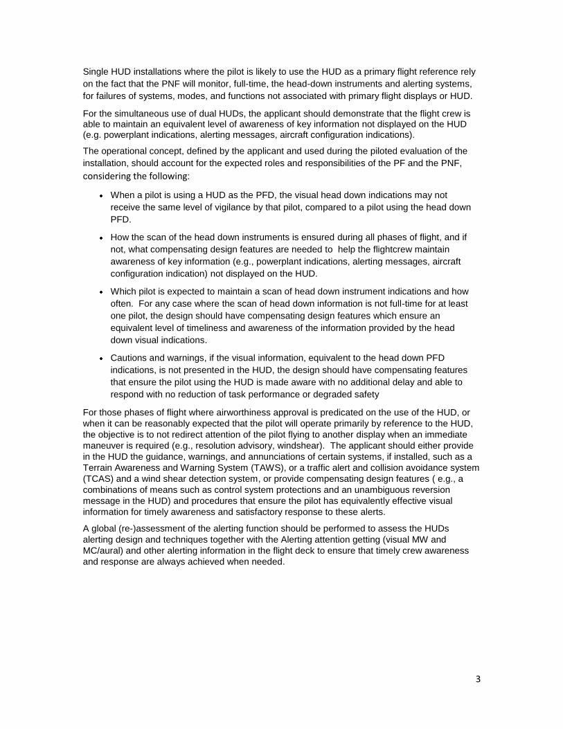
3
Single HUD installations where the pilot is likely to use the HUD as a primary flight reference rely
on the fact that the PNF will monitor, full-time, the head-down instruments and alerting systems,
for failures of systems, modes, and functions not associated with primary flight displays or HUD.
For the simultaneous use of dual HUDs, the applicant should demonstrate that the flight crew is able to maintain an equivalent level of awareness of key information not displayed on the HUD (e.g. powerplant indications, alerting messages, aircraft configuration indications).
The operational concept, defined by the applicant and used during the piloted evaluation of the
installation, should account for the expected roles and responsibilities of the PF and the PNF,
considering the following:
When a pilot is using a HUD as the PFD, the visual head down indications may not
receive the same level of vigilance by that pilot, compared to a pilot using the head down
PFD.
How the scan of the head down instruments is ensured during all phases of flight, and if
not, what compensating design features are needed to help the flightcrew maintain
awareness of key information (e.g., powerplant indications, alerting messages, aircraft
configuration indication) not displayed on the HUD.
Which pilot is expected to maintain a scan of head down instrument indications and how
often. For any case where the scan of head down information is not full-time for at least
one pilot, the design should have compensating design features which ensure an
equivalent level of timeliness and awareness of the information provided by the head
down visual indications.
Cautions and warnings, if the visual information, equivalent to the head down PFD
indications, is not presented in the HUD, the design should have compensating features
that ensure the pilot using the HUD is made aware with no additional delay and able to
respond with no reduction of task performance or degraded safety
For those phases of flight where airworthiness approval is predicated on the use of the HUD, or
when it can be reasonably expected that the pilot will operate primarily by reference to the HUD,
the objective is to not redirect attention of the pilot flying to another display when an immediate
maneuver is required (e.g., resolution advisory, windshear). The applicant should either provide
in the HUD the guidance, warnings, and annunciations of certain systems, if installed, such as a
Terrain Awareness and Warning System (TAWS), or a traffic alert and collision avoidance system
(TCAS) and a wind shear detection system, or provide compensating design features ( e.g., a
combinations of means such as control system protections and an unambiguous reversion
message in the HUD) and procedures that ensure the pilot has equivalently effective visual
information for timely awareness and satisfactory response to these alerts.
A global (re-)assessment of the alerting function should be performed to assess the HUDs
alerting design and techniques together with the Alerting attention getting (visual MW and
MC/aural) and other alerting information in the flight deck to ensure that timely crew awareness
and response are always achieved when needed.
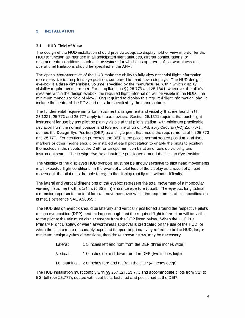
4
3 INSTALLATION
3.1 HUD Field of View
The design of the HUD installation should provide adequate display field-of-view in order for the HUD to function as intended in all anticipated flight attitudes, aircraft configurations, or environmental conditions, such as crosswinds, for which it is approved. All airworthiness and operational limitations should be specified in the AFM.
The optical characteristics of the HUD make the ability to fully view essential flight information more sensitive to the pilot's eye position, compared to head down displays. The HUD design eye-box is a three dimensional volume, specified by the manufacturer, within which display visibility requirements are met. For compliance to §§ 25.773 and 25.1301, whenever the pilot's eyes are within the design eyebox, the required flight information will be visible in the HUD. The minimum monocular field of view (FOV) required to display this required flight information, should include the center of the FOV and must be specified by the manufacturer.
The fundamental requirements for instrument arrangement and visibility that are found in §§
25.1321, 25.773 and 25.777 apply to these devices. Section 25.1321 requires that each flight
instrument for use by any pilot be plainly visible at that pilot’s station, with minimum practicable
deviation from the normal position and forward line of vision. Advisory Circular (AC) 25.773-1
defines the Design Eye Position (DEP) as a single point that meets the requirements of §§ 25.773
and 25.777. For certification purposes, the DEP is the pilot’s normal seated position, and fixed
markers or other means should be installed at each pilot station to enable the pilots to position
themselves in their seats at the DEP for an optimum combination of outside visibility and
instrument scan. The Design Eye Box should be positioned around the Design Eye Position.
The visibility of the displayed HUD symbols must not be unduly sensitive to pilot head movements
in all expected flight conditions. In the event of a total loss of the display as a result of a head
movement, the pilot must be able to regain the display rapidly and without difficulty.
The lateral and vertical dimensions of the eyebox represent the total movement of a monocular
viewing instrument with a 1/4 in. (6.35 mm) entrance aperture (pupil). The eye-box longitudinal
dimension represents the total fore-aft movement over which the requirement of this specification
is met. (Reference SAE AS8055).
The HUD design eyebox should be laterally and vertically positioned around the respective pilot's
design eye position (DEP), and be large enough that the required flight information will be visible
to the pilot at the minimum displacements from the DEP listed below. When the HUD is a
Primary Flight Display, or when airworthiness approval is predicated on the use of the HUD, or
when the pilot can be reasonably expected to operate primarily by reference to the HUD, larger
minimum design eyebox dimensions, than those shown below, may be necessary.
Lateral: 1.5 inches left and right from the DEP (three inches wide)
Vertical: 1.0 inches up and down from the DEP (two inches high)
Longitudinal: 2.0 inches fore and aft from the DEP (4 inches deep)
The HUD installation must comply with §§ 25.1321, 25.773 and accommodate pilots from 5’2” to
6’3” tall (per 25.777), seated with seat belts fastened and positioned at the DEP.

5
3.2 Obstruction of View
When installed, whether deployed or not, the HUD equipment must not create additional significant obstructions to either pilot's compartment view (§ 25.773). The equipment must not restrict either pilot's view of any controls, indicators or other flight instruments.
The HUD should not significantly degrade the necessary pilot compartment view of the outside world for normal, non-normal, or emergency flight maneuvers during any phase of flight for a pilot seated at the DEP. The HUD should be evaluated to ensure that it does not significantly affect the ability of any crewmember to spot other traffic, distinctly see approach lights, runways, signs, markings, or other aspects of the external visual scene.
The optical performance of the HUD must not degrade, distort or detract from the pilot's view of external references or in regards to seeing and avoiding other aircraft such that it would not enable them to safely perform any maneuvers within the operating limits of the airplane (§25.773). Where the windshield optically modifies the pilot's view of the outside world, the conformal HUD symbols must be optically consistent with the perceived outside view. The combination of the windshield and the HUD must meet the requirements of § 25.773(a)(1).
The optical qualities of the HUD should be uniform across the entire field of view. When viewed by both eyes from any off-center position within the eyebox, non-uniformities shall not produce perceivable differences in binocular view. Additional guidance is provided in ARP 5288.
3.3 Crew Safety
The HUD system must be designed and installed to prevent the possibility of pilot injury in the event of an accident or any other foreseeable circumstance such as turbulence, hard landing, bird strike, etc. The installation of the HUD, including overhead unit and combiner, must comply with the head injury criteria (HIC) of § 25.562 (c)(5). Additionally, the HUD installation must comply with the retention requirements of § 25.789(a) and occupant injury requirements of §§ 25.785 (d) and (k).
For a dual HUD installation, there is the potential for both pilots to experience an incapacitating injury as a result of flight or gust loads. This becomes a safety of flight issue, since the entire flightcrew would be incapacitated. The types of injuries of concern may be long duration, low impact, high load, as opposed to the high impact, short duration injuries assessed by HIC. A dedicated method of compliance may be needed should analysis of the installation geometry indicate that flight or gust loads will produce occupant contact with the HUD installation.
For compliance to §§ 25.803, 25.1307, 25.1411 and 25.1447, the HUD installation must not interfere with or restrict the use of other installed equipment such as emergency oxygen masks, headsets, or microphones. The installation of the HUD must not adversely affect the emergency egress provisions for the flight crew, or significantly interfere with crew access. The system must not hinder the crew's movement while conducting any flight procedures.
3.4 HUD Controls
For compliance to § 25.777, the means of controlling the HUD, including its configuration and display modes, must be visible to, identifiable, accessible, and within the reach of, the pilots from their normal seated position. For compliance to §§ 25.777, 25.789 and 25.1301, the position and movement of the HUD controls must not lead to inadvertent operation. For compliance to § 25.1381, the HUD controls must be adequately illuminated for all normal ambient lighting conditions, and must not create any objectionable reflections on the HUD or other flight instruments. Unless a fixed level of illumination is satisfactory under all lighting conditions, there should be a means to control its intensity.

6
To the greatest extent practicable, the HUD controls should be integrated with other associated flight deck controls, to minimize the crew workload associated with HUD operation and to enable flightcrew awareness.
HUD controls, including the controls to change or select HUD modes, should be implemented to minimize pilot workload for data selection or data entry and allow the pilot to easily view and perform all mode control selections from his seated position.
4 INFORMATION PRESENTATION
4.1 Displayed Information
The HUD information display requirements will depend on the intended function of the HUD. Specific guidance for displayed information is contained within the main body and Appendix 1 of this AC. In addition, the following sections provide guidance related to unique characteristics of the HUD. As in the case of other flight deck displays, new and/or novel display formats may be subject to an Authority human factors pilot interface evaluation(s).
4.1.1 Alternate Formats of Displaying Primary Flight Information
There may be certain operations and phases of flight during which certain primary flight reference indications in the HUD do not need to have the analog cues for trend, deviation, and quick glance awareness that would normally be necessary. For example, during the precision approach phase, HUD formats have been accepted that provide a digital only display of airspeed and altitude. Acceptance of these displays has been predicated on the availability of compensating features that provide clear and distinct warning to the flight crew when these and certain other parameters exceed well-defined tolerances around the nominal approach state (e.g., approach warning), and these warnings have associated procedures that require the termination of the approach.
Formats with digital-only display of primary flight information (e.g., airspeed, altitude, attitude, heading) should be demonstrated to provide at least:
a satisfactory level of task performance,
a satisfactory awareness of proximity to limit values, like Vs, VMO and VFE, or
a satisfactory means to avoid violating such limits.
If a different display format is used for go-around than that used for the approach, the format transition should occur automatically as a result of the normal go-around or missed approach procedure.
Changes in the display format and primary flight data arrangement should be minimized to prevent confusion and to enhance the pilots' ability to interpret vital data.
4.1.2 Aircraft Control Considerations
For those phases of flight where airworthiness approval is predicated on the use of the HUD, or when it can be reasonably expected that the pilot will operate primarily by reference to the HUD, the HUD should adequately provide:
information to permit instant pilot evaluation of the airplane's flight state and position. This should be shown to be adequate for manually controlling the airplane, and for monitoring the performance of the automatic flight control system. Use of the HUD for manual control of the airplane and monitoring of the automatic flight control system, should not

7
require exceptional skill, excessive workload, or excessive reference to other flight displays.
cues for the pilot to instantly recognize unusual attitudes and shall not hinder its recovery.
If the HUD is designed to provide guidance or information for recovery from upsets or
unusual attitudes, recovery steering guidance commands should be distinct from, and not
confused with, orientation symbology such as horizon “pointers.” This capability should
be shown for all foreseeable modes of upset, including crew mishandling, autopilot failure
(including "slowovers"), and turbulence/gust encounters.
4.1.3 Airspeed Considerations
As with other electronic flight displays, the HUD airspeed indications may not typically show the entire range of airspeed. Section 25.1541 (b)(2) of the Federal Aviation Regulations states: "The airplane must contain - Any additional information, instrument markings, and placards required for the safe operation if there are unusual design, operating, or handling characteristics. "
Low speed awareness cues presented on the HUD should provide adequate visual cues to the pilot that the airspeed is below the reference operating speed for the airplane configuration (i.e., weight, flap setting, landing gear position, etc.); similarly, high speed awareness cues should provide adequate visual cues to the pilot that the airspeed is approaching an established upper limit that may result in a hazardous operating condition.
The cues should be readily distinguishable from other markings such as V-speeds and speed targets (bugs). The cues should not only indicate the boundary value of speed limit, but also clearly distinguish between the normal speed range and the unsafe speed range beyond those limiting values. Cross-hatching may be acceptable to provide delineation between zones of different meaning.
4.1.4 Flight Path Considerations
An indication of the aircraft’s velocity vector, or flight path vector, is considered essential to most HUD applications. Earth-referenced flight path display information provides an instantaneous indication of where the aircraft is actually going. During an approach this information can be used to indicate the aircraft’s impact or touchdown point on the runway. The earth referenced flight path will show the effects of wind on the motion of the airplane. The flight path vector can be used by the pilot to set a precise climb or dive angle relative to the conformal outside scene or relative to the HUD’s flight path (pitch) reference scale and horizon displays. In the lateral axis the flight path symbols should indicate the aircraft track relative to the boresight.
Air mass derived flight path may be displayed as an alternative, but will not show the effects of wind on the motion of the airplane. In this case the lateral orientation of the flight path display represents the aircraft’s sideslip while the vertical position relative to the reference symbol represents the aircraft’s angle of attack.
The type of flight path information displayed (e.g., earth referenced, air mass) may be dependent on the operational characteristics of a particular aircraft and the phase of flight during which the flight path is to be displayed.
4.1.5 Attitude Considerations
An accurate, easy, quick glance interpretation of attitude by the pilot should be possible for all unusual attitude situations and command guidance display configurations. The pitch attitude

8
display should be such that during all maneuvers a horizon reference remains visible with enough margin to allow the pilot to recognize pitch and roll orientation. For HUDs that are capable of displaying the horizon conformally, display of a non-conformal horizon reference should be distinctly different than the display of a conformal horizon reference.
In addition, extreme attitude symbology and automatically decluttering the HUD at extreme attitudes has been found acceptable (extreme attitude symbology should not be visible during normal maneuvering).
When the HUD is designed not to be used for recovery from unusual attitude, there should be:
compensating features (e.g., characteristics of the airplane and the HUD system),
immediate direction to the pilot to use the head down PFD for recovery, and
satisfactory demonstration of timely recognition and correct recovery maneuvers.
4.2 Display Compatibility
The content, arrangement and format of the HUD information should be sufficiently compatible and consistent with the head down displays to preclude pilot confusion, misinterpretation, or excessive cognitive workload. Transitions between the HUD and head down displays, whether required by navigation duties, failure conditions, unusual airplane attitudes, or other reasons, should not present difficulties in data interpretation or delays/interruptions in the flight crew's ability to manually control the airplane or to monitor the automatic flight control system.
The HUD and HDD formats and data sources need to be compatible to ensure that the same information presented on both displays have the same intended meaning. HUD and HDD parameters should be consistent to avoid misinterpretation of similar information, but the display presentations need not be identical.
Deviation from these guidelines may be unavoidable due to conflict with other information display characteristics or requirements unique to head up displays. These may include minimization of display clutter, minimization of excessive symbol flashing, and the presentation of certain information conformal to the outside scene. Deviations from these guidelines will require additional pilot evaluation.
The following should be considered:
(a) Symbols that have the same meaning should be the same format; (b) Information (symbols) should appear in the same general location relative to other information; (c) Alphanumeric readouts should have the same resolution, units, and labeling (e.g., the command reference indication for “vertical speed” should be displayed in the same foot-per-minute increments and labeled with the same characters as the head-down displays); (d) Analogue scales or dials should have the same range and dynamic operation (e.g., a Glideslope Deviation Scale displayed head-up should have the same displayed range as the Glideslope Deviation Scale displayed head-down, and the direction of movement should be consistent); (e) FGS modes (e.g. autopilot, flight director, autothrust) and state transitions (e.g. land 2 to land 3) should be displayed on the HUD, and except for the use of colour, should be displayed using consistent methods (e.g., the method used head-down to indicate a flight director mode transitioning from armed to captured should also be used head-up); and (f) Information sources should be consistent between the HUD and the head-down displays used by the same pilot.
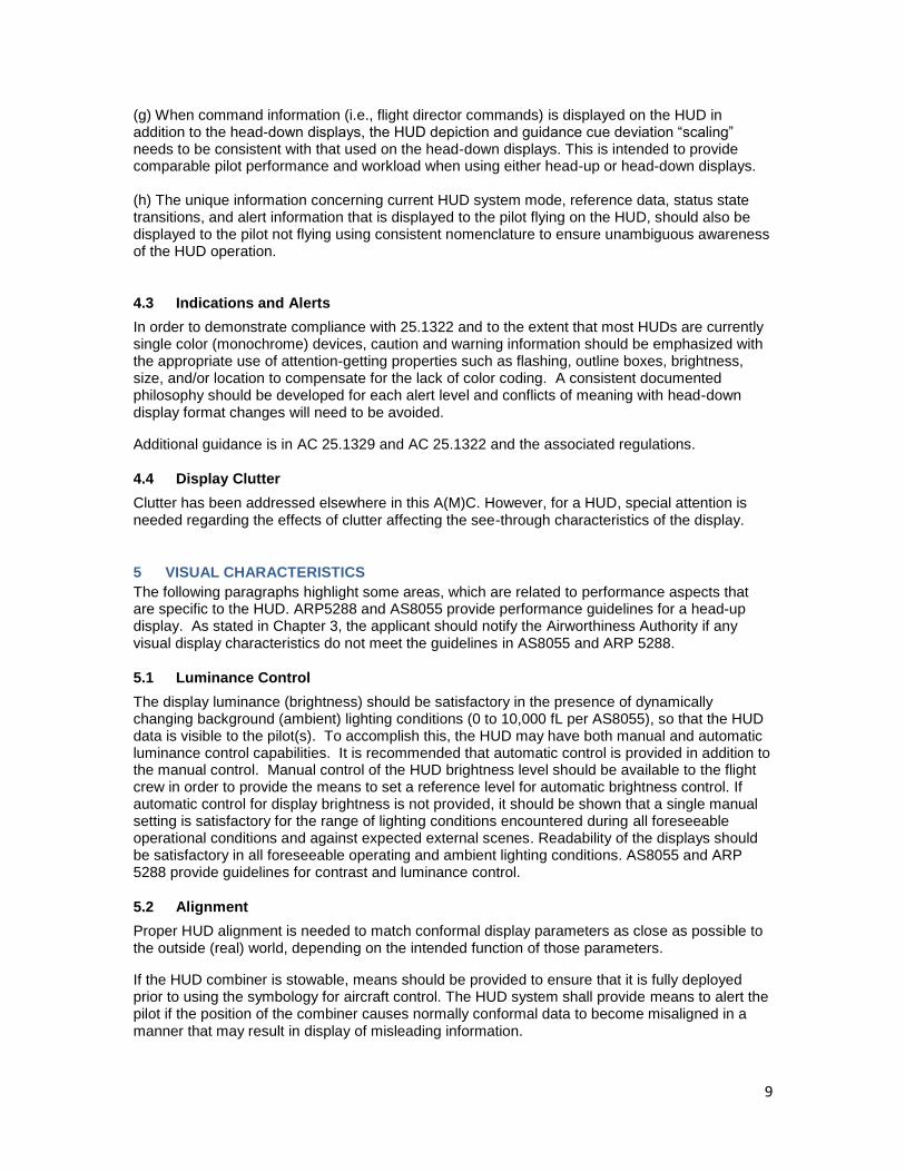
9
(g) When command information (i.e., flight director commands) is displayed on the HUD in addition to the head-down displays, the HUD depiction and guidance cue deviation “scaling” needs to be consistent with that used on the head-down displays. This is intended to provide comparable pilot performance and workload when using either head-up or head-down displays. (h) The unique information concerning current HUD system mode, reference data, status state transitions, and alert information that is displayed to the pilot flying on the HUD, should also be displayed to the pilot not flying using consistent nomenclature to ensure unambiguous awareness of the HUD operation.
4.3 Indications and Alerts
In order to demonstrate compliance with 25.1322 and to the extent that most HUDs are currently single color (monochrome) devices, caution and warning information should be emphasized with the appropriate use of attention-getting properties such as flashing, outline boxes, brightness, size, and/or location to compensate for the lack of color coding. A consistent documented philosophy should be developed for each alert level and conflicts of meaning with head-down display format changes will need to be avoided.
Additional guidance is in AC 25.1329 and AC 25.1322 and the associated regulations.
4.4 Display Clutter
Clutter has been addressed elsewhere in this A(M)C. However, for a HUD, special attention is needed regarding the effects of clutter affecting the see-through characteristics of the display.
5 VISUAL CHARACTERISTICS
The following paragraphs highlight some areas, which are related to performance aspects that are specific to the HUD. ARP5288 and AS8055 provide performance guidelines for a head-up display. As stated in Chapter 3, the applicant should notify the Airworthiness Authority if any visual display characteristics do not meet the guidelines in AS8055 and ARP 5288.
5.1 Luminance Control
The display luminance (brightness) should be satisfactory in the presence of dynamically changing background (ambient) lighting conditions (0 to 10,000 fL per AS8055), so that the HUD data is visible to the pilot(s). To accomplish this, the HUD may have both manual and automatic luminance control capabilities. It is recommended that automatic control is provided in addition to the manual control. Manual control of the HUD brightness level should be available to the flight crew in order to provide the means to set a reference level for automatic brightness control. If automatic control for display brightness is not provided, it should be shown that a single manual setting is satisfactory for the range of lighting conditions encountered during all foreseeable operational conditions and against expected external scenes. Readability of the displays should be satisfactory in all foreseeable operating and ambient lighting conditions. AS8055 and ARP 5288 provide guidelines for contrast and luminance control.
5.2 Alignment
Proper HUD alignment is needed to match conformal display parameters as close as possible to the outside (real) world, depending on the intended function of those parameters.
If the HUD combiner is stowable, means should be provided to ensure that it is fully deployed prior to using the symbology for aircraft control. The HUD system shall provide means to alert the pilot if the position of the combiner causes normally conformal data to become misaligned in a manner that may result in display of misleading information.

10
The range of motion of conformal symbology can present certain challenges in rapidly changing and high crosswind conditions. In certain cases, the motion of the guidance and the primary reference cue may be limited by the field of view. It should be shown that, in such cases, the guidance remains usable and that there is a positive indication that it is no longer conformal with the outside scene. It should also be shown that there is no interference between the indications of primary flight information and the flight guidance cues.
5.2.1 Symbol Positioning Accuracy (External)
External Symbol Positioning Accuracy, or Display Accuracy, is a measure of the relative
conformality of the HUD display with respect to the real world view seen by the pilot through the
combiner and windshield from any eye position within the HUD Eyebox. Display Accuracy is a
monocular measurement, and, for a fixed field point, is numerically equal to the angular difference
between the position of a real world feature as seen through the combiner and windshield, and
the HUD projected symbology.
The total HUD system display accuracy error budget (excluding sensor and windshield errors)
includes installation errors, digitization errors, electronic gain and offset errors, optical errors,
combiner positioning errors, errors associated with the CRT and yoke (if applicable),
misalignment errors, environmental conditions (i.e., temperature and vibration), and component
variations. Optical errors are both head position and field angle dependent and are comprised of
three sources: uncompensated pupil and field errors originating in the optical system aberrations,
image distortion errors, and manufacturing variations. The optical errors are statistically
determined by sampling the HUD FOV and Eyebox. (See 4.2.10 of SAE 8055 for a discussion of
field of view and Eyebox sampling);
The optical errors shall represent 95.4% (2 sigma) of all sampled points.
The display accuracy errors are characterized in both the horizontal and vertical planes.
Total display accuracy shall be characterized as the root-sum square (RSS) errors of
these two component errors.
All display errors shall be minimized across the display field of view consistent with the intended
function of the HUD. The following are the allowable display accuracy errors for a conformal HUD
as measured from the HUD Eye Reference Point:
HUD Boresight <= 5.0 mrad
<= 10° diameter <= 7.5 mrad (2 Sigma)
<= 30° diameter <=10.0 mrad (2 Sigma)
>30° diameter < 10 mrad + kr[(FOV)(in degrees) - 30)] (2 Sigma)
kr = 0.2 mrad of error per degree of FOV
The HUD manufacturer shall specify the maximum allowable installation error. In no case shall
the display accuracy error tolerances cause hazardously misleading data to be presented to the
pilot viewing the HUD.
5.2.2 Symbol Positioning Alignment
Symbols which are interpreted relative to each other shall be aligned to preclude erroneous
interpretation of information. Symbols which are not interpreted relative to each other may overlap
but shall not cause erroneous interpretation of display data, even when they overlap.
5.2.3 Combiner Position Alignment:
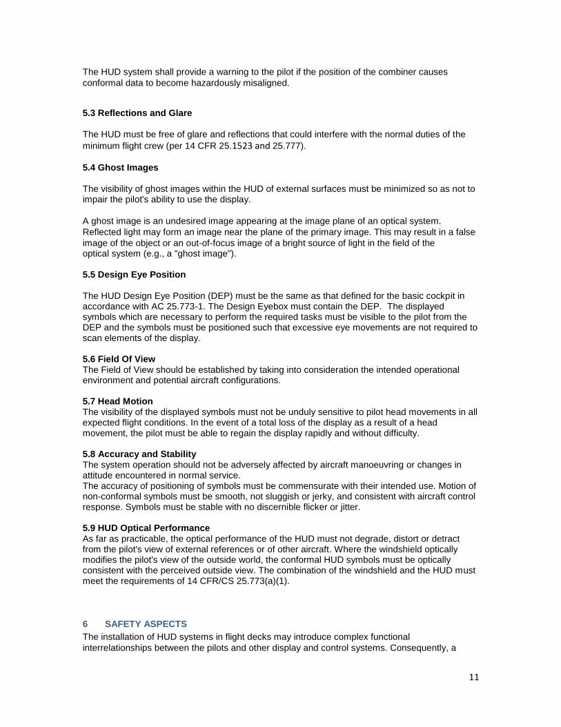
11
The HUD system shall provide a warning to the pilot if the position of the combiner causes
conformal data to become hazardously misaligned.
5.3 Reflections and Glare The HUD must be free of glare and reflections that could interfere with the normal duties of the
minimum flight crew (per 14 CFR 25.1523 and 25.777).
5.4 Ghost Images The visibility of ghost images within the HUD of external surfaces must be minimized so as not to impair the pilot's ability to use the display.
A ghost image is an undesired image appearing at the image plane of an optical system.
Reflected light may form an image near the plane of the primary image. This may result in a false
image of the object or an out-of-focus image of a bright source of light in the field of the optical system (e.g., a "ghost image"). 5.5 Design Eye Position
The HUD Design Eye Position (DEP) must be the same as that defined for the basic cockpit in accordance with AC 25.773-1. The Design Eyebox must contain the DEP. The displayed symbols which are necessary to perform the required tasks must be visible to the pilot from the DEP and the symbols must be positioned such that excessive eye movements are not required to scan elements of the display. 5.6 Field Of View The Field of View should be established by taking into consideration the intended operational environment and potential aircraft configurations. 5.7 Head Motion The visibility of the displayed symbols must not be unduly sensitive to pilot head movements in all expected flight conditions. In the event of a total loss of the display as a result of a head movement, the pilot must be able to regain the display rapidly and without difficulty. 5.8 Accuracy and Stability The system operation should not be adversely affected by aircraft manoeuvring or changes in attitude encountered in normal service. The accuracy of positioning of symbols must be commensurate with their intended use. Motion of non-conformal symbols must be smooth, not sluggish or jerky, and consistent with aircraft control response. Symbols must be stable with no discernible flicker or jitter. 5.9 HUD Optical Performance As far as practicable, the optical performance of the HUD must not degrade, distort or detract from the pilot's view of external references or of other aircraft. Where the windshield optically modifies the pilot's view of the outside world, the conformal HUD symbols must be optically consistent with the perceived outside view. The combination of the windshield and the HUD must meet the requirements of 14 CFR/CS 25.773(a)(1).
6 SAFETY ASPECTS
The installation of HUD systems in flight decks may introduce complex functional
interrelationships between the pilots and other display and control systems. Consequently, a

12
Functional Hazard Assessment (FHA) which requires a top down approach, from an airplane
level perspective, should be developed in accordance with FAR/CS 25.1309. Development of a
FHA for a particular installation requires careful consideration of the role the HUD plays within the
flight deck in terms of integrity of function and availability of function, as well the operational
concept of the installation to be certified (dual vs single, type and amount of information
displayed, etc.). Chapter 4 of this AC provides material that may be useful in supporting the FHA
preparation.
All alleviating flight crew actions that are considered in the HUD safety analysis need to be
validated for incorporation in the airplane flight manual procedures section or for inclusion in type-
specific training.
Since the flight information displayed on the HUD is visible only to one pilot, and since in most
cases, failures of flight parameters shown on the HUD are not independent of those shown on the
same pilot’s head down primary flight display, the HUD may not be a suitable means to comply
with 25.1333(b) following loss of primary head down flight displays. The rule requires that at least
one display of information essential to safety of flight remain available to the (both) pilots, not just
one pilot.
7 CONTINUED AIRWORTHINESS
Depending on the type of operation and the intended function of the HUD, instructions for the continued airworthiness of a display system and its components have to be prepared to show compliance with §§ 25.1309 and 25.1529 (including Appendix H)
8 FLIGHT DATA RECORDING
The installation of HUDs has design aspects and unique operational characteristics requiring
specific accident recording considerations. HUD guidance modes and status (in use or
inoperative) and display declutter mode should be considered to be recorded to comply with §
25.1459(e) and 121.344.

1
Appendix W Weather Displays
1. Background and Scope: This appendix provides additional guidance for displaying weather information in the flight
deck. Weather displays provide the flight crew with additional tools to help the flight crew
make decisions based on weather information.
Sources of weather information may include, but would not be limited to: onboard, real-time
weather, data-linked weather, turbulence information, pilot/air traffic reports, and may be
displayed in a variety of graphical or text formats.
Because there are many sources of weather information, it is important that the applicant identify
and assess the intended function for a particular source and display of weather information, and
apply the guidance contained within this AC/AMC.
2. Key Characteristics In addition to the general guidelines provided in this AC, there are unique aspects of the display
of weather information so that the information is being used as intended.
A. The display should enable the flight crew to quickly, accurately, and consistently
differentiate among sources of displayed weather, as well as differentiate between time-
critical weather information and dated, non-time critical weather information.
B. Weather presentations (display format, the use of colors, labels, data formats, and
interaction with other display parameters) should be clear and unambiguous and not
result in a flight crew member’s misunderstanding or misinterpretation of the weather
information being displayed. Weather displays may use red and amber/yellow provided
that all of the following criteria are met;
1. The use of color is in compliance with 14 CFR/CS 25.1322, AC 25.1322, and this
AC.
2. The use of color is appropriate to the task and context of use, and,
3. The proposed use does not affect the attention getting qualities of flight crew alerting
and does not adversely affect the alerting functions across the flight deck, and,
4. Color conventions (such as ARINC 708; AC 20-149) are utilized.
Note: AC 20-149 indicates an exclusion to the acceptability of DO-267A (paragraph 7.d) for part
25 airplanes.
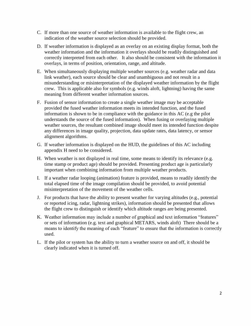
2
C. If more than one source of weather information is available to the flight crew, an
indication of the weather source selection should be provided.
D. If weather information is displayed as an overlay on an existing display format, both the
weather information and the information it overlays should be readily distinguished and
correctly interpreted from each other. It also should be consistent with the information it
overlays, in terms of position, orientation, range, and altitude.
E. When simultaneously displaying multiple weather sources (e.g. weather radar and data
link weather), each source should be clear and unambiguous and not result in a
misunderstanding or misinterpretation of the displayed weather information by the flight
crew. This is applicable also for symbols (e.g. winds aloft, lightning) having the same
meaning from different weather information sources.
F. Fusion of sensor information to create a single weather image may be acceptable
provided the fused weather information meets its intended function, and the fused
information is shown to be in compliance with the guidance in this AC (e.g the pilot
understands the source of the fused information). When fusing or overlaying multiple
weather sources, the resultant combined image should meet its intended function despite
any differences in image quality, projection, data update rates, data latency, or sensor
alignment algorithms.
G. If weather information is displayed on the HUD, the guidelines of this AC including
appendix H need to be considered.
H. When weather is not displayed in real time, some means to identify its relevance (e.g.
time stamp or product age) should be provided. Presenting product age is particularly
important when combining information from multiple weather products.
I. If a weather radar looping (animation) feature is provided, means to readily identify the
total elapsed time of the image compilation should be provided, to avoid potential
misinterpretation of the movement of the weather cells.
J. For products that have the ability to present weather for varying altitudes (e.g., potential
or reported icing, radar, lightning strikes), information should be presented that allows
the flight crew to distinguish or identify which altitude ranges are being presented.
K. Weather information may include a number of graphical and text information “features”
or sets of information (e.g. text and graphical METARS, winds aloft) There should be a
means to identify the meaning of each “feature” to ensure that the information is correctly
used.
L. If the pilot or system has the ability to turn a weather source on and off, it should be
clearly indicated when it is turned off.

3
M. When weather information is presented in a vertical situation display (VSD), it should be
depicted sufficiently wide to contain the weather information that is relevant to the
current phase of flight or flight path. In addition:
1. Weather information displayed on VSD shall be accurately depicted with respect to
the scale factors of the display (i.e., vertical and horizontal), all vertical path
information displayed, including glide slope, approach path, or angle of descent.
2. Consideration should be given to making the weather information display width
consistent with the display width used by other systems, including Terrain Awareness
and Warning System (TAWS), if displayed.
3. On-Board Weather Radar Information On-Board Weather Radar may provide forward-looking weather detection, including windshear
and turbulence detection.
The display of on-board weather radar information should be in accordance with the applicable
portions of RTCA DO-220, “Minimum Operational Performance Standards for Airborne
Weather Radar With Forward-Looking Windshear Capability.”
The weather display echoes from precipitation and ground returns should be clear, automatic,
timely, concise and distinct for rapid pilot interpretation so flight crews can easily analyze and
avoid areas of detected hazards. The radar range, elevation, and azimuth indications should
provide sufficient indication to the flight crew to allow for safe avoidance maneuvers.
4. Predictive Windshear Information The display of windshear information, if provided, should be clear, automatic, timely, concise
and distinct for rapid pilot interpretation so flight crews can easily detect and avoid areas of
windshear activity.
When a windshear threat is detected, the corresponding display may be automatically presented
or selected by pilot action, at a range which is appropriate to identify the windshear threat. Pilot
workload necessary for its presentation should be minimized and should not take more than one
action when the cockpit is configured for normal operating procedures.
The display of a predictive windshear threat, including relative position and azimuth with respect
to the nose of the airplane, should be presented in an unambiguous manner to effectively assist
the flight crew in responding to the windshear threat; the symbol should be presented in
accordance with DO-220.
The size and location of the windshear threat should be presented using a symbol that is
sufficient to allow the pilot to recognize and respond to the threat
The range selected by the pilot for the windshear display should be sufficient to allow the pilot to
distinguish the event from other displayed information. Amber radial lines may be used to
4
extend from the left and right radial boundaries of the icon extending to the upper edge of the
display.
5. Safety Aspects Both the loss of weather information plus the display of misleading weather information should
be addressed in the functional hazard assessment (FHA). In particular, this should only address
failures of the display system that could result in loss of or misleading weather information, not
the sensor itself.
In accordance with paragraph 4 of this AC, display of misleading weather radar includes the
display of weather radar information that would lead the pilot to make a bad decision and
introduce a potential hazard. Examples of misleading weather radar information include, but are
not limited to: storm cells presented on the display that are not in the correct position, are at the
wrong intensity, not displayed when they should be displayed, or mis-registered in the case of a
combined (e.g fused) image.
1
AIA SLD Working Group

2
Background
IPHWG submitted results of Task 2, Phase IV review to TAEIG for review/vote
March 19th, 2009
After submittal, some new concerns were raised by IPHWG members
IPHWG consensus could not be obtained prior to the June ’09 TAEIG meeting
After TAEIG discussion, a vote was held to accept the IPHWG recommendation as presented, but include the concerns with the submittal

3
Background (continued)
A teleconference was held with the IPHWG to discuss the concerns
Were notified by FAA that TAEIG’s vote to approve the working group report had completed the ARAC assigned tasks
IPHWG had no authority to meet or provide further recommendations
Any further discussions must be documented as required disclosure of “Ex Parte” contacts
Possible to continue discussions as an industry group
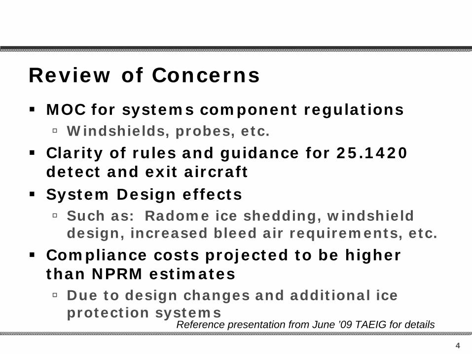
4
Review of Concerns
MOC for systems component regulations
Windshields, probes, etc.
Clarity of rules and guidance for 25.1420 detect and exit aircraft
System Design effects
Such as: Radome ice shedding, windshield design, increased bleed air requirements, etc.
Compliance costs projected to be higher than NPRM estimates
Due to design changes and additional ice protection systems
Reference presentation from June ’09 TAEIG for details

5
AIA SLD Working Group
An AIA “ad hoc” SLD Working Group was formed to review the issues
Concerns remain after more detailed reviewPrimary concerns are with compliance methods as
discussed in guidance materialsPotential for reduced regulatory benefits due to
additional compliance costs (initial as well as recurring)
Will the draft advisory materials be released as part of the NPRM?
Is the June date for NPRM publication still accurate?
What are the options for the industry working group recommendations at this stage of rulemaking?
What options are there for recommending changes to advisory materials?

6
Discussion/Questions?