
APS-3 with FieldGenius -...
54
APS-3 with FieldGenius Configuration Manual Version 1.3
Transcript of APS-3 with FieldGenius -...

APS-3 with FieldGenius Configuration Manual
Version 1.3

1
1
1
Table of contents
1 Getting Started .................................................................................... 2
1.1 Hardware requirements ..................................................................................... 2
1.2 Installing FIELDGenius ......................................................................................... 2
2 Septentrio FIELDGenius Startup ........................................................ 3
2.1 Launch Septentrio FieldGenius .......................................................................... 3
2.2 Create a new project ........................................................................................... 4
2.2.1 Give the project a name ......................................................................................... 4
2.2.2 Unit Settings ............................................................................................................ 5
2.2.3 Coordinate System Settings .................................................................................. 5
3 Instrument Selection .......................................................................... 6
3.1 GPS Reference ...................................................................................................... 6
3.1.1 Add GPS Reference Profile .................................................................................... 6
3.1.2 Model and Communication ................................................................................... 7
3.1.3 Set a Reference Position ...................................................................................... 12
3.1.4 Link Configure ....................................................................................................... 20
3.1.5 Instrument Disconnect ........................................................................................ 23
3.2 GPS Rover ............................................................................................................ 25
3.2.1 Add GPS Rover Profile .......................................................................................... 26
3.2.2 Model and Communication ................................................................................. 27
3.2.3 Link Configure ....................................................................................................... 31
3.2.4 Raw Data Logging ................................................................................................. 42
4 Additional Functions ......................................................................... 46
4.1 Check APS-3 Battery Levels .............................................................................. 46
4.2 Check RTK Corrections (Link Information) ..................................................... 48
4.3 Measurement ..................................................................................................... 49
5 Technical Support .............................................................................. 51
6 Appendix ............................................................................................ 52
6.1 Antenna Offsets ................................................................................................. 52
6.1.1 NGS Calibration ..................................................................................................... 52
6.1.2 Slant Height Dimensions ..................................................................................... 53
2
2
Getting Started
2
1 Getting Started
1.1 Hardware requirements
FIELDGenius 8 may be installed on most Windows CE, PocketPC, and Windows Mobile
devices, as well as any Desktop, Laptop, or Tablet PC running Windows XP SP3, Windows
Vista SP2, or Windows 7.
For a complete list of compatible mobile devices, please refer to MicroSurvey Software’s
FIELDGenius manual.
1.2 Installing FIELDGenius
If you purchased a new data collector with FIELDGenius 8 from Septentrio, it should come
pre-loaded with Septentrio FieldGenius software. If it is not installed, or you need to
upgrade to a newer version, please perform these steps:
Establish a Microsoft ActiveSync or Windows Mobile Device Center connection
between your computer and data collector.
Locate and execute the FIELDGenius 8 install file, found either on the CD that
came with your purchase or downloaded from www.septentrio.com/support.
(Credentials can be provided by Septentrio support team). Follow the prompts to
complete install.

3
3
Septentrio FIELDGenius Startup
3
2 Septentrio FIELDGenius Startup
Before Power On of the APS-3, ensure the following are done:
SD card and SIM card (if used) are installed and rear door closed
UHF antenna is connected
Batteries are installed
Note the serial number of the APS-3 (located on the underside) for Bluetooth
identification within the program.
2.1 Launch Septentrio FieldGenius
Launch FIELDGenius by
selecting the program from
the Start menu.
The Splash screen will
then appear.

4
4
Septentrio FIELDGenius Startup
4
2.2 Create a new project
Create a new project by selecting New Project
from the Project Manager screen.
2.2.1 Give the project a
name
Double-tap the project name field to
begin typing
Enter a name for your project.
Select OK.
5
5
Septentrio FIELDGenius Startup
5
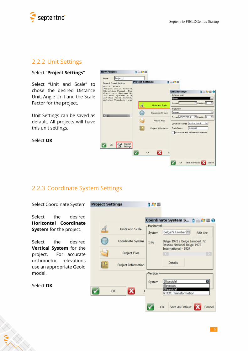
2.2.2 Unit Settings
Select “Project Settings”
Select “Unit and Scale” to
chose the desired Distance
Unit, Angle Unit and the Scale
Factor for the project.
Unit Settings can be saved as
default. All projects will have
this unit settings.
Select OK
2.2.3 Coordinate System Settings
Select Coordinate System
Select the desired
Horizontal Coordinate
System for the project.
Select the desired
Vertical System for the
project. For accurate
orthometric elevations
use an appropriate Geoid
model.
Select OK.

6
6
Instrument Selection
6
3 Instrument Selection
3.1 GPS Reference
3.1.1 Add GPS Reference Profile
Select GNSS Reference
Select Add
Very important: It is not possible to
output corrections from the base (RTCM
messages) without having a position.
Use the serial number of the APS-3 for
easy identification
Select Save.
7
7
Instrument Selection
7
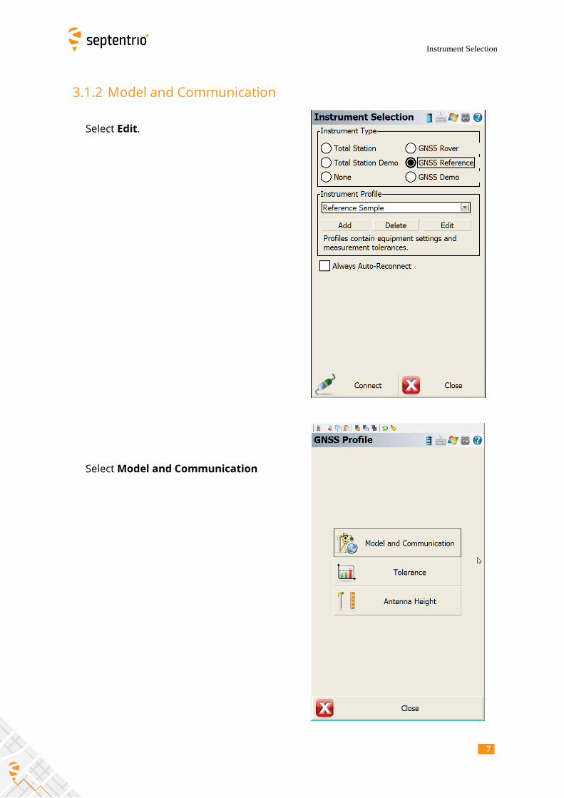
3.1.2 Model and Communication
Select Edit.
Select Model and Communication

8
8
Instrument Selection
8
Select Altus for Make
Select the appropriate Model from the
drop-down menu.
Note: The APS-3 model can be determined
by the Serial Number on the underside of
the unit.
For serial numbers in the 10000 series,
select APS-3 Rev 1.
For serial numbers in the 20000 series,
select APS-3 Rev 2.
3.1.2.1 Bluetooth Pairing
Select Bluetooth as the Port.
Select Bluetooth Device List

9
9
Instrument Selection
9
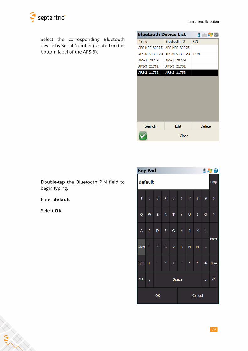
Select the corresponding Bluetooth device
by Serial Number (located on the bottom
label of the APS-3).
If the device is not in the list, select
Refresh List.
Double-tap the Bluetooth PIN field to
begin typing.

10 1
Instrument Selection
10
Enter default
Select OK.
Select Close

11 1
Instrument Selection
11
Select Connect.
Verify the Bluetooth LED on the APS-
3 Reference comes on.
12 1
Instrument Selection
12
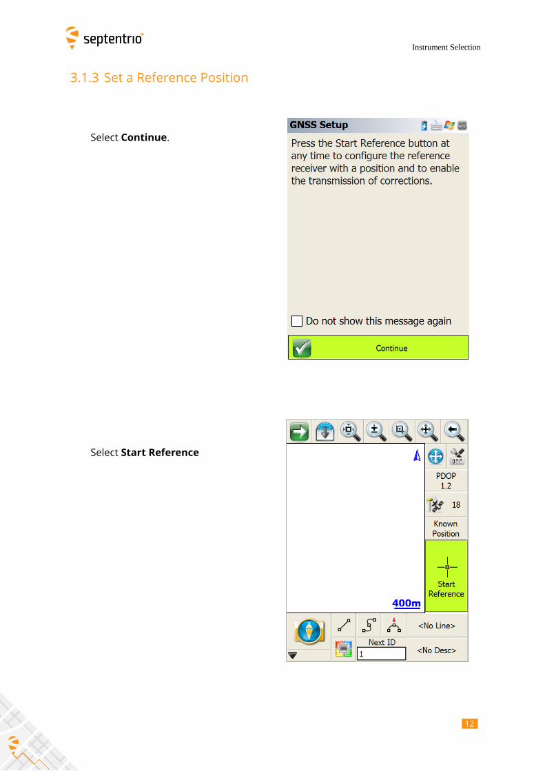
3.1.3 Set a Reference Position
Select Continue.
Select Start Reference
13 1
Instrument Selection
13
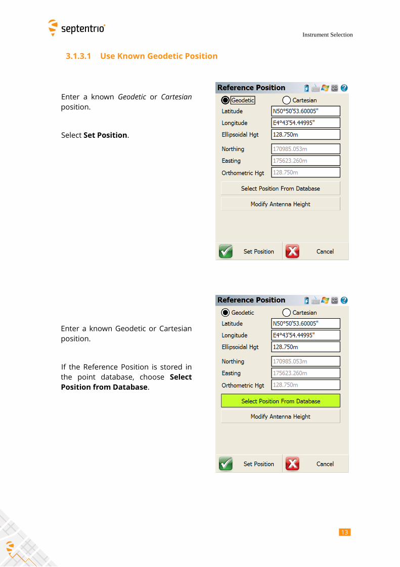
3.1.3.1 Use Known Geodetic Position
Enter a known Geodetic or Cartesian
position.
Select Set Position.
Enter a known Geodetic or Cartesian
position.
If the Reference Position is stored in
the point database, choose Select
Position from Database.

14 1
Instrument Selection
14
Enter the Point ID if known, or select
List.
Select the point representing the
Reference position.
Choose Select

15 1
Instrument Selection
15
Choose Select
Select Modify Antenna Height
16 1
Instrument Selection
16
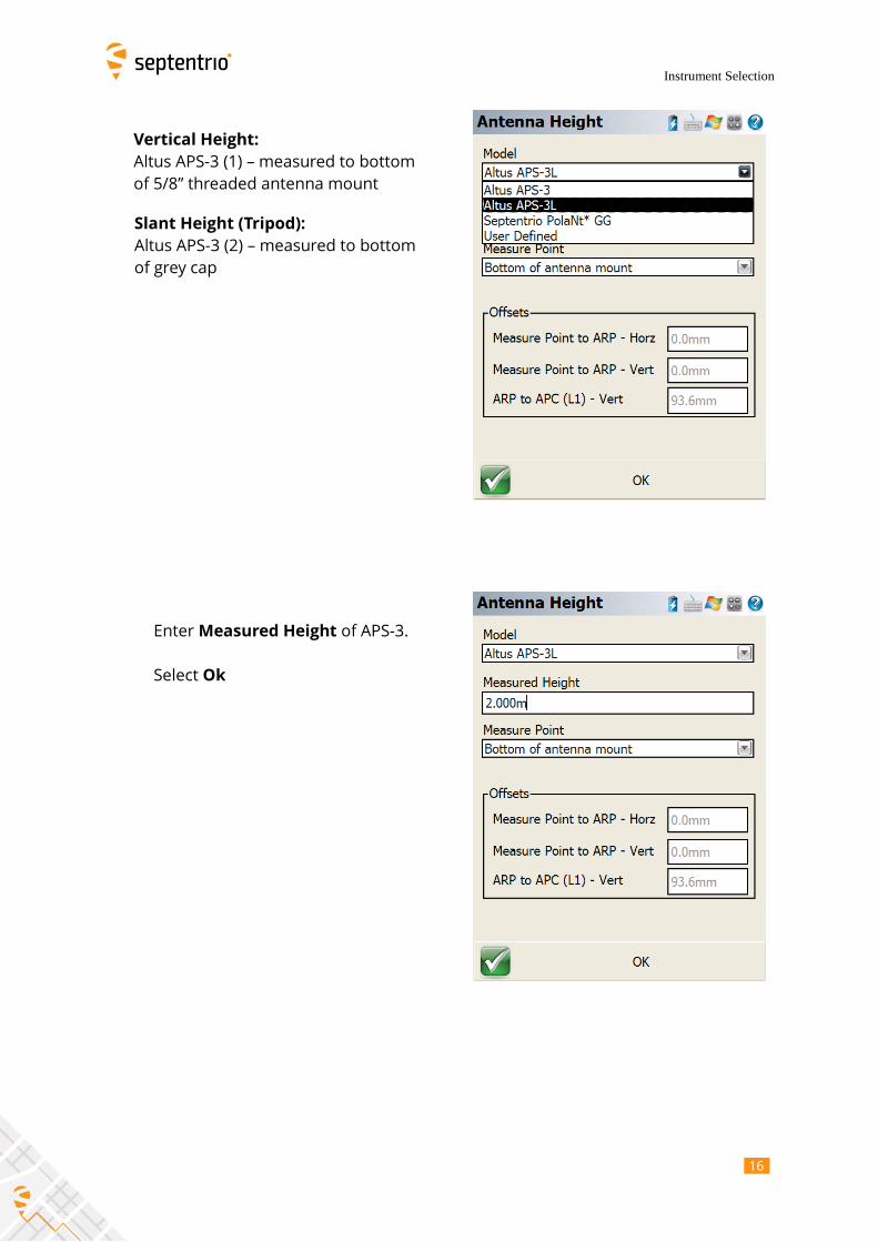
Vertical Height:
Altus APS-3 (1) – measured to bottom
of 5/8” threaded antenna mount
Slant Height (Tripod):
Altus APS-3 (2) – measured to bottom
of grey cap
Enter Measured Height of APS-3.
Select Ok

17 1
Instrument Selection
17
Select Set Position
3.1.3.2 Use Averaged Geodetic Position
Select Averaged Geodetic Position

18 1
Instrument Selection
18
Select Yes to save the Reference
Position to the points database.
Enter a Description for the Reference
Position.

19 1
Instrument Selection
19
Select Store Pnt
If prompted, select Yes to add the
description to the automap library.

20 2
Instrument Selection
20
3.1.4 Link Configure
3.1.4.1 Data Format
The Data Format must match at both
Reference and Rover to receive RTK
corrections.
RTCM 3 format is recommended
3.1.4.2 Internal UHF Radio
Satel Radio:
Link Device: Select Satel
Link Communication: Set GPS Port to
Internal Device to use the internal UHF
radio
Data Format: Set Data Port to RTCM 3
Select Setup

21 2
Instrument Selection
21
Select the desired Channel
number/frequency.
The Channel frequency must match at
both Reference and Rover to receive
RTK corrections.
Select the desired Channel spacing.

22 2
Instrument Selection
22
Select the desired Protocol (Satel is
recommended).
The Protocol type must match at both
Reference and Rover to receive RTK
corrections.
The FEC setting must match at both
Reference and Rover to receive RTK
corrections.

23 2
Instrument Selection
23
Select a Transmit Power for the
internal radio.
500mW gives optimal performance.
Note that a higher transmit power is a
trade-off between range and power
consumption.
Select OK to complete the Reference
configuration
3.1.5 Instrument Disconnect

24 2
Instrument Selection
24
Select to open the Instrument
Settings menu.
Select Instrument Disconnect

25 2
Instrument Selection
25
3.2 GPS Rover
Select to open the Instrument
Selection menu.
A GPS Rover Instrument Profile must be
created before first use
From Instrument Type, select GNSS
Rover
From Instrument Profile, select an
existing APS-3 Rover profile, or select
Internal GPS to Create a new one.

26 2
Instrument Selection
26
3.2.1 Add GPS Rover Profile
Select Add to create a new GPS Rover profile
Enter a name for the Instrument Profile that
identifies the APS-3 Rover by serial number.
Select Ok and then Save.

27 2
Instrument Selection
27
Select Edit
3.2.2 Model and Communication
Select Model and Communication

28 2
Instrument Selection
28
Select Altus for Make
Select the appropriate Model from the
drop-down menu.
Note: The APS-3 model can be
determined by the Serial Number on
the underside of the unit.
For serial numbers in the 10000 series,
select APS-3 Rev1.
For serial numbers in the 20000 series,
select APS-3 Rev 2.
3.2.2.1 Bluetooth Pairing
Select Bluetooth as the Port
Select Bluetooth Search
29 2
Instrument Selection
29
Select the corresponding Bluetooth
device by Serial Number (located on the
bottom label of the APS-3).
Double-tap the Bluetooth PIN field to
begin typing.
Enter default
Select OK

30 3
Instrument Selection
30
Select Connect
Verify the Bluetooth LED on the APS-3
Reference comes on.

31 3
Instrument Selection
31
3.2.3 Link Configure
Select to open the Instrument Settings menu and select Link Configure.
3.2.3.1 Data Format
The Data Format must match at both
Reference and rover to receive RTK
corrections.
RTCM 3 format is recommended
32 3
Instrument Selection
32
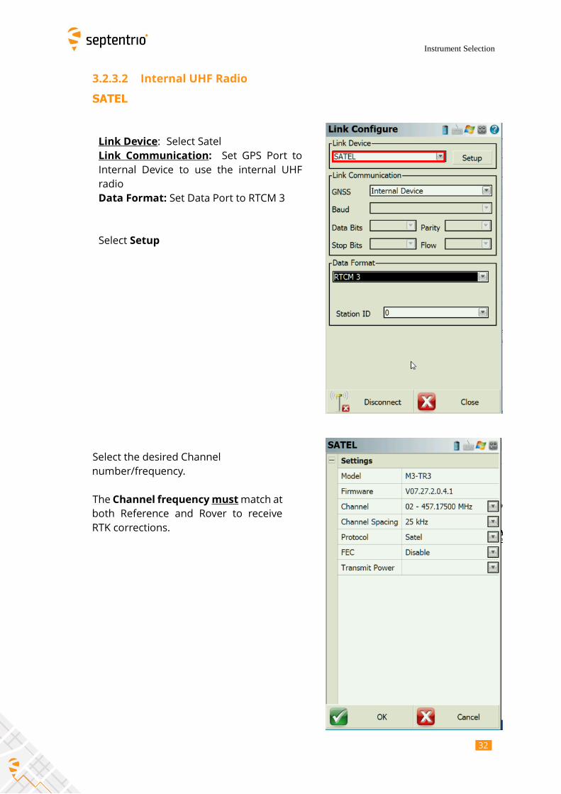
3.2.3.2 Internal UHF Radio
SATEL
Link Device: Select Satel
Link Communication: Set GPS Port to
Internal Device to use the internal UHF
radio
Data Format: Set Data Port to RTCM 3
Select Setup
Select the desired Channel
number/frequency.
The Channel frequency must match at
both Reference and Rover to receive
RTK corrections.

33 3
Instrument Selection
33
Select the desired Channel spacing.
Select the desired Protocol (Satel is
recommended).
The Protocol type must match at both
Reference and Rover to receive RTK
corrections.

34 3
Instrument Selection
34
The FEC setting must match at both
Reference and Rover to receive RTK
corrections.
Select a Transmit Power for the
internal radio.
500mW gives optimal performance.
Note that a higher transmit power is a
trade-off between range and power
consumption.

35 3
Instrument Selection
35
Select OK to complete the Rover
configuration
Device configuration is now completed

36 3
Instrument Selection
36
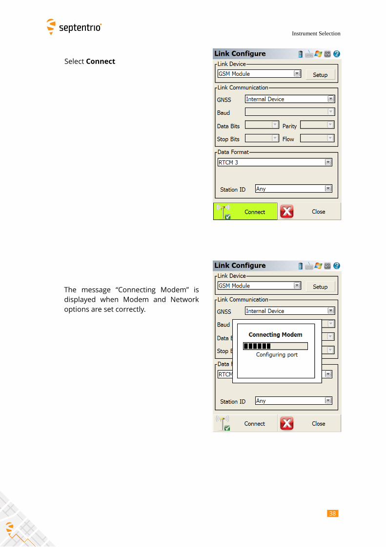
3.2.3.3 Internal GSM Modem
Link Device: GSM Module
Link Communication: select Internal
Device
Select Setup
For Data Source, select either GPRS
(TCP/IP) or NTRIP

37 3
Instrument Selection
37
For Network Options, enter the specific
settings for the SIM card used.
An APN server name must be entered,
even if the other Network Options are
blank.
Select Press to Modify to enter the
connection details for the RTK network
being accessed under NTRIP Options.
An NTRIP connection requires:
User ID
Password
IP Address
TCP/IP Port
A GPRS connection requires:
IP Address
TCP/IP Port
Select Ok
38 3
Instrument Selection
38
Select Connect
The message “Connecting Modem” is
displayed when Modem and Network
options are set correctly.

39 3
Instrument Selection
39
Select Request Sourcetable
The sourcetable is requested from the
network.

40 4
Instrument Selection
40
Select the desired Mount Point.
Choose Select
Select the desired Correction Format.
RTCM 3 format is recommended.

41 4
Instrument Selection
41
Wait few seconds.
When “RTK Fixed” is achieved the survey
may begin.

42 4
Instrument Selection
42
3.2.4 Raw Data Logging
Select to open the Instrument
Settings menu.
Select Raw Data Logging
43 4
Instrument Selection
43
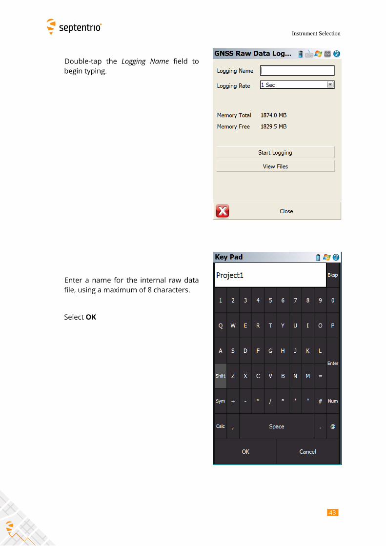
Double-tap the Logging Name field to
begin typing.
Enter a name for the internal raw data
file, using a maximum of 8 characters.
Select OK

44 4
Instrument Selection
44
Select a Logging Rate for the data file.
Select Start Logging to begin writing the
data file to the internal SD card.
Verify the Internal Data Logging LED on
the APS-3 comes on.
45 4
Instrument Selection
45
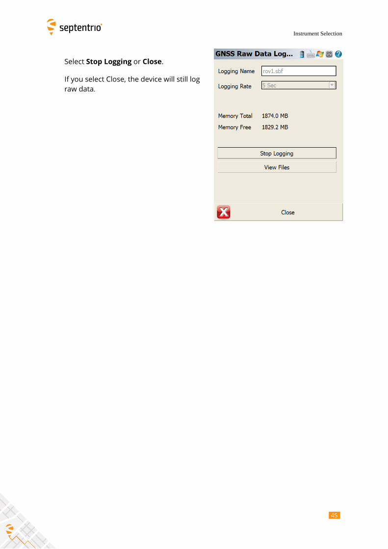
Select Stop Logging or Close.
If you select Close, the device will still log
raw data.

46 4
Additional Functions
46
4 Additional Functions
4.1 Check APS-3 Battery Levels
Select to open the Instrument
Settings menu.
Select Sensor Information

47 4
Additional Functions
47
View levels for Battery A (Right) and
Battery B (Left).
In this example, Battery A has been
depleted and is in Stand By. It is safe to
remove Battery A and replace with a
charged battery for continued
operation. This is known as “Hot
Swapping”.
Removing an In Use battery will
restart the APS-3.

48 4
Additional Functions
48
4.2 Check RTK Corrections (Link Information)
Select to open the Instrument
Settings menu.
Select Link Information

49 4
Additional Functions
49
View Data Age to confirm RTK
corrections are updating frequently.
4.3 Measurement
Select to measure a point.

50 5
Additional Functions
50
Select Store Position.
The tolerance can be changed selecting
and then “Sensor Configuration”.
It is possible to give a name to the point
to measure, description, etc.
When finished, select Store Pnt

51 5
Technical Support
51
5 Technical Support
For any further questions about configuring the APS-3 with Septentrio FieldGenius, which
may not be covered in this manual, contact your local dealer.
Email Septentrio technical support at [email protected]
Apart from configuring the APS-3 GNSS receiver, additional information and support for
Septentrio FieldGenius software features are available from MicroSurvey Software’s
Technical Support and website.
MicroSurvey offers a 90-day complimentary support period for all registered users. Please
visit their helpdesk at http://www.microsurvey.com/helpdesk/ to create a support ticket
or search for solutions.

52 5
Appendix
52
6 Appendix
6.1 Antenna Offsets
6.1.1 NGS Calibration
Phase Center Location
NGS Vertical Offsets Absolute Relative
L1 Offset (mm) 95.3 113.5 L2 Offset (mm) 86.4 94.1
Absolute - http://www.ngs.noaa.gov/ANTCAL/LoadFile?file=APS_APS-3_NONE.003 APS_APS-3 NONE ALTUS GNSS RCVR/ANT, P/N:10015, PNL TO N NGS ( 3)
08/10/07
1.3 -0.5 95.3
0.0 1.1 1.8 2.1 2.0 1.6 1.1 0.6 0.2 -0.1
-0.3 -0.4 -0.4 -0.4 -0.4 -0.2 0.1 0.0 0.0
-1.0 3.2 86.4
0.0 -1.0 -1.4 -1.3 -1.0 -0.6 -0.3 -0.3 -0.5 -0.9
-1.5 -2.0 -2.5 -2.9 -3.2 -3.2 -2.5 0.0 0.0
Relative - http://www.ngs.noaa.gov/ANTCAL/LoadFile?file=ant_info.003 APS_APS-3 NONE ALTUS GNSS RCVR/ANT, P/N:10015, PNL TO N NGS ( 3)
08/10/07
0.7 -0.1 113.5
0.0 1.3 2.7 4.0 5.2 6.2 7.1 7.7 8.1 8.1
7.8 7.0 5.8 4.1 1.9 -0.9 -4.4 0.0 0.0
-0.9 3.8 94.1
0.0 -0.9 -0.9 -0.2 0.8 2.0 3.1 3.9 4.3 4.3
3.8 2.9 1.5 -0.1 -1.9 -3.7 -5.3 0.0 0.0

53 5
Appendix
53
6.1.2 Slant Height Dimensions
Height of ARP=√(Slant Height)2-0.089𝑚2-0.0606m