Approximate Analysis of the Temperature Induced Stresses and Deformations...
23
Approximate Analysis of the Temperature Induced Stresses and Deformations of Composite Shells LAszLO P. KoLLAR* Department of Aeronautics and Astronautics Stanford University Stanford, CA 94305 (Received February 5, 1993) ABSTRACT: In this paper simple formulas are presented which can be used to estimate the response of composite plates and shells to hygrothermal loads. The layup of the shell can be arbitrary (i.e., it can be symmetric or unsymmetric, bal- anced or unbalanced). The formulas serve two purposes. First, they can be used to calculate directly the stresses, strains, and displacements caused by a temperature and a moisture gradient. Sec- ond, the formulas can be used to determine the "effective" thermal and moisture expansion coefficients which are the parameters needed in more accurate numerical (FEM) calcula- tions. The accuracies of the approximate formulas were assessed by sample problems. In these problems the hygrothermal deformations of cylinders and cylindrical segments were calculated by the present approximate formulas and by an exact, three-dimensional analy- sis. The results of the exact and approximate methods were compared. These comparisons showed that the approximate formulas yield the deformations with a high degree of ac- curacy. 1. INTRODUCTION C OMPOSITE CYLINDERS AND cylindrical segments are important structural elements. Their response to a change in temperature (or moisture content) is unexpected; the curvature of cylindrical segments with symmetric layups changes when they are subjected to a constant change in temperature. (This plays the ma- jor role in the angle change occurring in the corners of composite laminates dur- ing cure, e.g., References [1-61.) This phenomenon is referred to as "springback" (or "spring-forward"). It occurs because of the thickening of the laminate, or *Visiting associate professor. On leave from the Technical University of Budapest, Department of Reinforced Con- crete Structures, Hungary-1521. 392 Journal of COMPOSITE MATERIALS, Vol. 28, No. 5/1994 0021-9983/94/05 392-23 $6.00/0 © 1994 Technomic Publishing Co., Inc.
Transcript of Approximate Analysis of the Temperature Induced Stresses and Deformations...
Approximate Analysis of the TemperatureInduced Stresses and Deformations
of Composite Shells
LAszLO P. KoLLAR*Department of Aeronautics and Astronautics
Stanford UniversityStanford, CA 94305
(Received February 5, 1993)
ABSTRACT: In this paper simple formulas are presented which can be used to estimatethe response of composite plates and shells to hygrothermal loads.
The layup of the shell can be arbitrary (i.e., it can be symmetric or unsymmetric, bal-anced or unbalanced).
The formulas serve two purposes. First, they can be used to calculate directly thestresses, strains, and displacements caused by a temperature and a moisture gradient. Sec-ond, the formulas can be used to determine the "effective" thermal and moisture expansioncoefficients which are the parameters needed in more accurate numerical (FEM) calcula-tions.
The accuracies of the approximate formulas were assessed by sample problems. In theseproblems the hygrothermal deformations of cylinders and cylindrical segments werecalculated by the present approximate formulas and by an exact, three-dimensional analy-sis. The results of the exact and approximate methods were compared. These comparisonsshowed that the approximate formulas yield the deformations with a high degree of ac-curacy.
1. INTRODUCTION
C OMPOSITE CYLINDERS AND cylindrical segments are important structuralelements. Their response to a change in temperature (or moisture content) is
unexpected; the curvature of cylindrical segments with symmetric layups changeswhen they are subjected to a constant change in temperature. (This plays the ma-jor role in the angle change occurring in the corners of composite laminates dur-ing cure, e.g., References [1-61.) This phenomenon is referred to as "springback"(or "spring-forward"). It occurs because of the thickening of the laminate, or
*Visiting associate professor. On leave from the Technical University of Budapest, Department of Reinforced Con-crete Structures, Hungary-1521.
392 Journal of COMPOSITE MATERIALS, Vol. 28, No. 5/1994
0021-9983/94/05 392-23 $6.00/0© 1994 Technomic Publishing Co., Inc.

Temperature Induced Stresses and Deformations of Composite Shells 393
more precisely, because of the difference between the in-plane and out-of-planestrains in the plies due to the change in temperature and moisture content [1-6].
This effect can be investigated by three-dimensional elasticity solutions [5-11],by three-dimensional finite element methods (e.g., References [2,4]) or by higherorder shell theories [12].
Our aim is to determine simple formulas instead of 3-D analysis, based on theclassical laminated plate theory [13], to calculate the stresses and strains in com-posite shells with arbitrary layups subjected to constant and linear temperatureand moisture gradients.
Approximate formulas were derived only for cylindrical segments with sym-metric layups subjected to a constant change in temperature ([2,3] see Equation(39) of this paper), not for unsymmetric, unbalanced, doubly curved shells.
2. PROBLEM STATEMENT
Consider a composite shell which consists of unidirectional fiber reinforcedplies. There is no restriction on the orientation of the plies, the laminate can beunsymmetric and unbalanced. The middle surface of the shell can be flat, cylin-drical, or any doubly curved shape (Figure 1). The shell is subjected to lineartemperature and moisture gradients through the thickness:
AT = AT + zAT„ Ac = Ac, + zzlc (1)
where z is the coordinate perpendicular to the surface, and z is equal to zero onthe middle surface. The aim is to determine the stresses and deformations in thecomposite shell.
For plates and cylinders, we will give the expressions of stresses and strains.For general shells only the "effective thermal expansion coefficients" and the "ef-fective moisture expansion coefficients" [13-15] which are necessary inputs in theconstitutive relationships for more efficient (analytical or numerical) calcula-tions. The constitutive law is the following:
(Z) = (AB DD) i( Ex) — T. (X TO) — AT (x:,) — Aco (X :̀.) — AC, (x:,)i
(2)
where N and M are the vectors of forces and moments induced in the shell, A,
Figure 1. The structures considered.
394
LAszLO P. KOLLAR
B, and D are the stiffness matrices, E° and x are the vectors of strains and curva-ture changes of the middle surface. 6- 0 ,x, 0 , and 0- 1 0( 7- 1 are the "effective ther-mal expansion coefficients" for constant and linear change in temperature; andec'0 ,,Go, and are the "effective moisture expansion coefficients" for con-stant and linear change in moisture.
3. METHOD OF SOLUTION
Temperature and moisture affect the deformations of a shell in a similar man-ner [Equation (2)]. For simplicity hereafter we include only the temperature inthe analysis with the understanding that the moisture content can be included inan identical manner as the temperature.
The deformations of a laminated composite shell will be calculated using thethin shell approximation [16]. However, the effect of "thickening" due to thechange in temperature will be taken into account by modifying the effective ther-mal expansion coefficients.
The calculation of deformations and stresses will be evaluated in three steps:
1. First we investigate a plate which has the same layup as the shell in question.We apply a constant change in temperature (AT = AT = 1) and determinethe deformations of the middle surface. These deformations, the in planestrains (0- 0 ,„) and the curvatures (x 7- 0, ,,) are the "effective thermal expan-sion coefficients" of a plate for a constant change in temperature. Then we ap-ply a linear change in temperature (AT = zAT, = z) and determine thedeformations of the middle surface. These deformations (El . i, „ i,„) arethe "effective thermal expansion coefficients" of a plate for a linear change intemperature. Due to the above loads the thickness of the plate may change,which causes no additional stresses.
2. Second, we modify the effective thermal expansion coefficients calculated fora plate taking into account the effect of the curved middle surface. Note thatthis modification may vary with position on the middle surface depending onthe shell geometry.
3. In order to solve for the deformation in a shell with given geometry, loads,and boundary conditions, we have to consider the equilibrium, strain-displacement, and constitutive relationships. The constitutive law is given byEquation (2). To solve these equations we can use any analytical or numerical(FEM) method, which provides the displacements, stresses and strains in theshell. The solution of the aforementioned equation system is not the subjectof this paper, but instead we concentrate on the determination of the effectivethermal expansion coefficients. However, we will consider some simple casesin which the approximate deformations may readily be obtained: cylindersand cylindrical segments subjected to a change in temperature which variesthrough the thickness but not along the surface.
We assume that the material behaves in a linearly elastic manner, the deforma-tions are small, and the normals of the undeformed middle surface remainstraight and normal to the middle surface after the deformations.

Temperature Induced Stresses and Deformations of Composite Shells 395
3=z
Figure 2. The build up of the laminate and the coordinate system.
4. EFFECTIVE THERMAL EXPANSION COEFFICIENTSOF COMPOSITE PLATES
The first step, as we mentioned in the previous section, is to determine thedeformations of a composite plate due to the change in temperature.
4.1 Notations and Definitions
We use the classical laminated plate theory. The global, off axis, coordinatesystem is 1,2,3, while the local, on axis coordinate system is x, y, z (Figure 2).The origin of both coordinate systems is on the middle surface. The basic nota-tions and the well-known relationships [13] are listed in Table 1.
In the laminated plate theory, plane stress is assumed. The out-of-plane straincan be calculated as follows [13]:
where
S„,p —
Er = S„,„a
.)
(3)
(4)
The on axis thermal expansion coefficients are denoted by a_ay,az
4.2 Effective Thermal Expansion Coefficientsfor Constant Change in Temperature
Let an unconstrained plate be subjected to the constant change in temperature:AT = AT, = 1. The strains and curvatures of the middle surface due to thisloading (denoted by E3- 0. ,, and x T o ,p ) are the effective thermal expansion coeffi-cients for a constant change in temperature.

396
LAszLO P. KOLLAR
Table 1. Stresses and strains in the laminated plate theory. The superscriptsx and 1 refer to the coordinate systems x,y,z and 1,2,3 respectively.
If there is no superscript, the stress or strain is in the global1,2,3 coordinate system.
Strains
Stresses
Ex =
fi x =
1 or e = " 6:12)
ac:ss) or 0=0'=::
ay
:)
Generalized strains in the middle surface:
(1 1
E° = E°' = E'; and x = x' = x2d )r,
E = E° + Z X
Generalized stresses in the middle surface:
N, M,N = N' = N, = adz and M = M' = M, = za'dz
N, (h) /1/h (h)
Constitutive Equations
(E" — AT«) = S'a" a" = C1"(E" — ATa)
where
1 - Pyx
ExEx
- Pyx 1S' —
Ex T,
0 0
0
0 a =
'10 and Q" = [ST
1Es (continued)
Temperature Induced Stresses and Deformations of Composite Shells 397
Table 1. (continued).
Constitutive equations for a plate if the change in temperature is zero:
((M) B tglA, B, and D are given in Reference [1].
Transformations between stresses, strains, and stiffnesses:
a x = Jug', Ex = 1x1-1E = Q = kild'OxP
where
and J; 2 is the transpose of J12.
cos' a1,Jiy = sin' am
- cos au sin coy
sin' aix
COS' cox
cos cox sin «Ix
2 cos co x Sin a12
—2 cos a lx sin cox(cos' a l , - sin' coy)
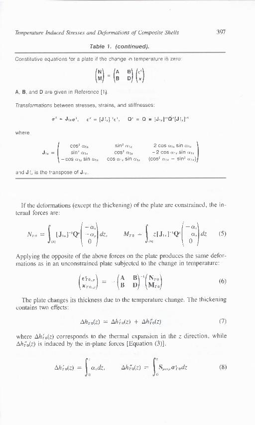
If the deformations (except the thickening) of the plate are constrained, the in-ternal forces are:
— a, — a„NTO = [J ij-V" — ay dZ, MTO = Z[J1x] -1Q' —ay dz (5)
(h) 0 (h) 0
Applying the opposite of the above forces on the plate produces the same defor-mations as in an unconstrained plate subjected to the change in temperature:
XTO,p1 (AB DB) ' (MNT:13)
(6)
The plate changes its thickness due to the temperature change. The thickeningcontains two effects:
Ah T0(z) = 0(z) + .K0(z) (7)
where A16 0(z) corresponds to the thermal expansion in the z direction, whileOho(z) is induced by the in-plane forces [Equation (3)].
AN- 0(z) = adz, AhA(z) = Sperp (qodz (8)0 0
where
with
398
LAszLO P. KOLLAR
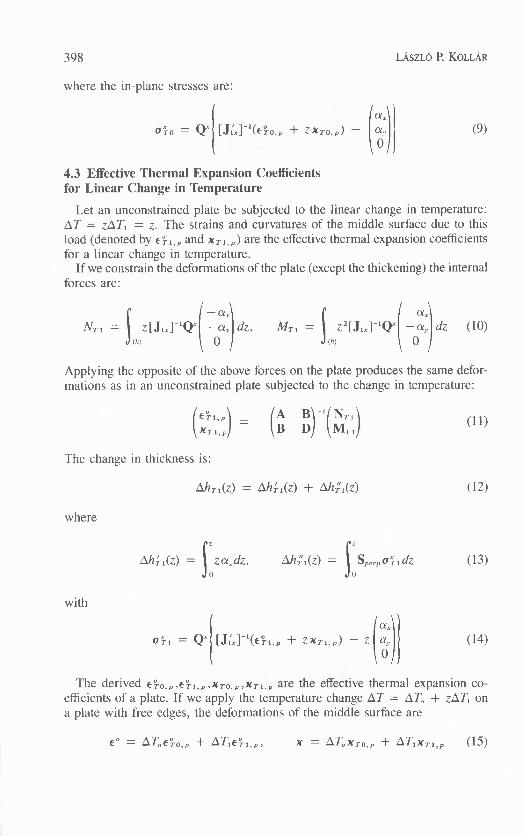
where the in-plane stresses are:
a)}= Q'[K,]-1(6-0,, + zxTo,p) — ay (9)
0
4.3 Effective Thermal Expansion Coefficientsfor Linear Change in Temperature
Let an unconstrained plate be subjected to the linear change in temperature:AT = zATi = z. The strains and curvatures of the middle surface due to thisload (denoted by E7 1, , and x T , ,p ) are the effective thermal expansion coefficientsfor a linear change in temperature.
If we constrain the deformations of the plate (except the thickening) the internalforces are:
NT , = z[1.1 -1 (r —04 dz, M7' 1 = Z2P lx1 -1 (r( —a, dz (10)(h) 0 (h) 0
Applying the opposite of the above forces on the plate produces the same defor-mations as in an unconstrained plate subjected to the change in temperature:
()= ( AB D) I ( MNTT1)XT1,p
The change in thickness is:
AhT1(z) = ANi(z) + AhCi(z) (12)
6,h; i(z) = zceAz, AWi(z) = Sp,oi,dz (13)0 0
a Tl = Qx[Ed-'(E3-1,„ + zxTi,p) — za„,ax)1
(14)
The derived 6-0,p,eri,p,XTo,p,X7-1,p are the effective thermal expansion co-efficients of a plate. If we apply the temperature change AT = AT 0 + z,AT, ona plate with free edges, the deformations of the middle surface are
0
E° = AT„€3 0,p +
x = ATo xro ,p + ATi xr i,p (15)
Temperature Induced Stresses and Deformations of Composite Shells 399
However, if the middle surface is curved, we have to modify these deforma-tions as it will be shown in the next section.
5. THERMAL EXPANSION COEFFICIENTS OF COMPOSITE SHELLS
In this section we will investigate the stresses and deformations which must beadded to those in a plate, caused by the thickening of the shell and by the stretch-ing of the middle surface. First we introduce a new coordinate system,where is perpendicular to the surface, E, n are in the planes of the principal cur-vatures. The radii of curvatures of the shell in the and in then, planes aredenoted by RE and R,,.
Let us transform the effective thermal expansion coefficients into the E,nscoordinate system:
= = [K,E] -1 XT,p (16)
In this section we apply the subscript T instead of TO or Tl, with the understand-ing that the expressions are valid for both the constant and the linear temperaturedistribution.
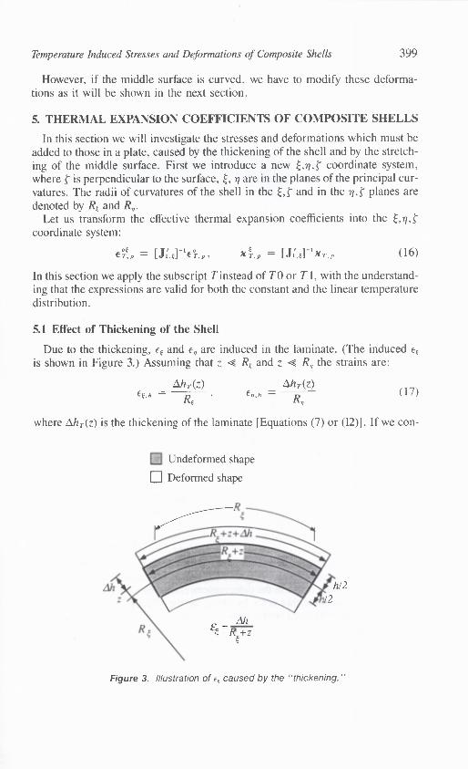
5.1 Effect of Thickening of the Shell
Due to the thickening, Et and e, are induced in the laminate. (The induced Et
is shown in Figure 3.) Assuming that z 4 RE and z R, the strains are:
Oh T (Z) Zih, (z) Et. h RE ' R,
where Ai/Az) is the thickening of the laminate [Equations (7) or (12)]. If we con-
Undeformed shape
q Deformed shape
Figure 3. Illustration of E E caused by the "thickening."
(17)
400
LAsnO P. KOLLAR
strain the deformations the internal stresses are as follows:
Nh = Q[Etl(En,h)dz,(h) 0
Mh
Et, h
zQ[Et]€„,)dz (18)(h) 0
Applying the opposite of these forces, the additional deformations of the middlesurface due to the thickening can be calculated:
=, ( AB D) 1 ( MNh h)XTh
5.2 Effect of Stretching of the Middle Surface of the Shell
In the laminated plate theory the strains (c) in a plate can be calculated fromthe deformations (6° and x) of the middle surface:
E = + z x
or in the coordinate system:
E E = EZ zxt , En = zx„, -yE„ = + zx t ,, (20)
These are also the usual approximations of thin shell theory. However, in a shellthe strains are not linear through the thickness, we can approximate them as[16,17]
E E = + zxt)(1 — Rt E, = (E zx„)(I —
(21)70/ = Z En
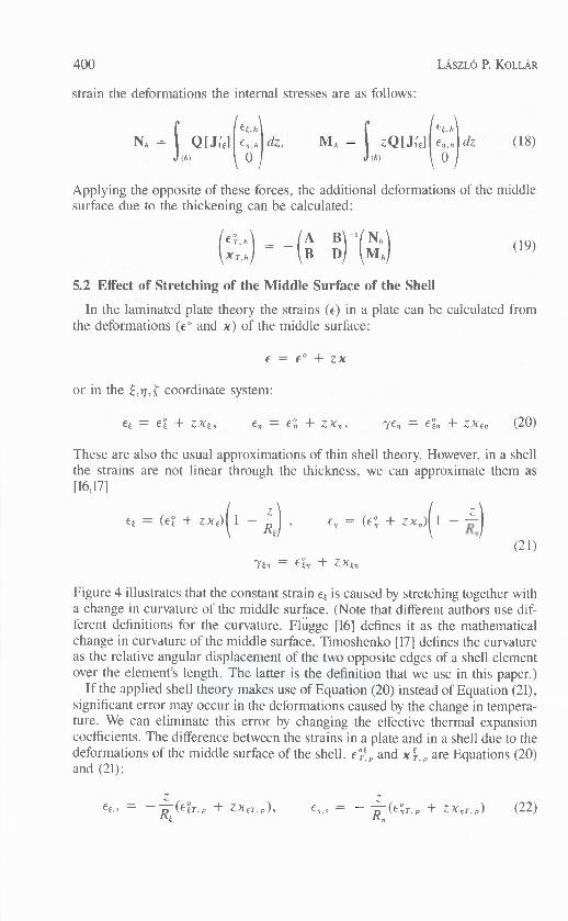
Figure 4 illustrates that the constant strain Et is caused by stretching together witha change in curvature of the middle surface. (Note that different authors use dif-ferent definitions for the curvature. Flugge [16] defines it as the mathematicalchange in curvature of the middle surface. Timoshenko [17] defines the curvatureas the relative angular displacement of the two opposite edges of a shell elementover the element's length. The latter is the definition that we use in this paper.)
If the applied shell theory makes use of Equation (20) instead of Equation (21),significant error may occur in the deformations caused by the change in tempera-ture. We can eliminate this error by changing the effective thermal expansioncoefficients. The difference between the strains in a plate and in a shell due to thedeformations of the middle surface of the shell, c",E, „ and x;, , „ are Equations (20)and (21):
(19)
E t, s = (E p Z X ET, p ), = Ten(E,'IT,p zxo-,p ) (22)
Temperature Induced Stresses and Deformations of Composite Shells 401
Undeformed shape
q Deformed shape1
Figure 4. Illustration of a constant e t caused by "stretching" and change in curvature of themiddle surface.
where OT, p and c°,77- ,p are the first two elements of E T!, and xer ,p and x„T,p arethe first two elements of [Equation (21)]. To get the deformations of themiddle surface we have to follow the same steps as in the case of the thickening.If we constrain the deformations the internal stresses are as follows:
Et,,
Ns = QiEtlen , ․)dz, M. = dz (23)(h) 0 (h) 0
Applying the opposite of these forces, the additional deformations caused by thestretching of the middle surface can be calculated:
(xT, ․ )
(AB D13)-1(MN)
(24)
5.3 The Effective Thermal Expansion CoefficientsTo get the effective thermal expansion coefficients for a shell we have to modify
those of a plate. For constant or linear change in temperature:
( () () (0., ․ )
XT XT,p XT,h XT,s
- - -plate thickening stretching
The terms in Equation (25) are defined by Equations (6), (11), (19) and (24).
(25)
402 LAszLO P. KOLLM2
5.4 Stresses in a Ply
In the calculation of stresses in a shell we have to take into account the thicken-ing and the stretching of the middle surface. Hence the stresses are:
a' = Q' (E° + zx)—AT,J,',, ce, — A To i; t 1{ (%
0—R
[ — A h T 0(z) + Z(E4o,, + ZX,ro,p)]
—1--AhTo(z) + z(E4 0, „ + zxuo,p)1
,
0
1 —Ahn(z) + Z(Ci r 1,p + ZXET1,p)]
— zATI L( ay — AT1Ea,
—1?
[— Ahn(z) + ZX,r1,010
0
••••■■,,,■,*
plate thickening stretching(26)
where E° and x are the deformations of the middle surface.Let us emphasize again that the terms due to the "stretching" are necessary only
if shell theory defines the curvature due to Reference [17] and make use of Equa-tion (20).
5.5 Approximate Calculation of the Thermal ExpansionCoefficients for Constant Change in Temperature
We can further simplify the expressions derived in the previous sections forconstant change in temperature approximating the displacement h (z) [Equation(7)] by a linear function:
.h(z) = zcx., p(27)
and neglecting the second (quadratic) terms in Equation (22)
zZ—EE,s =— T,p,
= R E 'IT'"RE „(28)
/(
E. )
X TO
— ( _f *Ti 0 2 )
\X 1.0p)
+
/1F(RE
000
1TO,P — a..p)
'
(30)
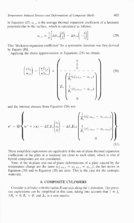
Temperature Induced Stresses and Deformations of Composite Shells 403
In Equation (27) a =, „ is the average thermal expansion coefficient of a laminateperpendicular to the surface, which is calculated as follows:
a''P = [Ah (1ONTO( 11
1
TO 2 2
This "thickness expansion coefficient" for a symmetric laminate was first derivedby Pagano [181.
Applying the above approximation in Equations (25) we obtain:
(29)
Ez 1 ,
Ri,TO,p — az,p),kel
\ 0 //
and the internal stresses from Equation (26) are:
a' = I' + Z X) — AT .L(ar — AT,„L',z 1
,
0
lei T p — « T)
R, (6°, TO,p — az,TO,p)
RE
a
F. ..o.p
0 /
\ 1/ 1 ,
(31)
These simplified expressions are applicable if the out-of-plane thermal expansioncoefficients of the plies in a laminate are close to each other, which is true ifhybrid composites are not considered.
Note, if the in-plane and out-of-plane deformations of a plate caused by thetemperature change are the same (6'i.TO.p = en.TO.p = a, ,p ), the last terms inEquation (30) and in Equation (31) are zero. This is the case for the isotropicmaterials.
6. COMPOSITE CYLINDERS
Consider a cylinder with the radius R and axis along the 1 direction. The previ-ous expressions can be simplified in this case, taking into account that 1 ---7- E,1/RE = 0, R, = R, and I t is a unit matrix.

404 LAszLO P. KOLLAR
The approximate expression for a constant change in temperature [Equation(30)] is:
01ero,p\)6.0,p)
WI TO — a 1
0
and the internal stresses are:
ETO)XTO
000
0(32)
/ 0
a' =a,
° + zx) — AT0J,',a) — AToz0 R1/ TO — )
' (33)
0 /
The third step in the solution (see "Method of Solution" Section) is to deter-mine the stresses and deformations in the shell due to the applied loads consider-ing the equilibrium equations and the relationships between the strains anddisplacements.
The displacements of the middle surface in the axial x,, circumferential 0 (orx2), and radial r (or x3) directions are denoted by u, v, and w, respectively. Therelationships between the displacements and the deformations of the middle sur-face of the cylinder are [17]:
au aV w au aVEl = E2ax, Rae R ' — Rae ax
a2w
XI — axt
(34)
1 (av a 2 w 1 (av a2w)X2 R 2 ae 30 2 ) '6 R ax axae
If the strains are constant in the cylinder, x, must be zero and the expressionsfor the displacements from Equation (34) are as follows:
U = OR(E6 — Rx6)
v = OR 2 x 2 + xRx6 (35)
w R(e2 — Rx2)
S= 3
Temperature Induced Stresses and Deformations of Composite Shells 405
6.1 Cylindrical Segments
Consider a cylindrical segment subjected to a change in temperature whichdoes not vary on the surface. In this case, the deformations of the middle surface(E°,x) and the forces (N,M) are constant in the shell (except in the neighborhoodof the curved boundaries). Hence we can determine the twelve elements of(E°,x,N,M) from the following twelve equations:
( MN) = (AB DB) t(cx°) _ O[°(X7) _
,6,7,1(x`4-T1,)} (36)
N, = 0, M, = 0, M6 = 0, x, = 0
(37)
Knowing E° and x the stresses in the segment can be calculated from Equation(26).
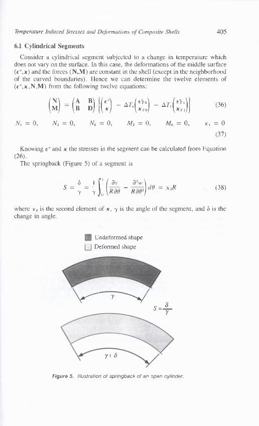
The springback (Figure 5) of a segment is
S = a = ay — a2w )c10 = x2R7 7 0 Rao Raw
where x 2 is the second element of x, y is the angle of the segment, and (5 is thechange in angle.
Undeformed shape
111 Deformed shape
(38)
y+
Figure 5. Illustration of springback of an open cylinder.
406
LAszLO P. KOLLAR
If a cylindrical segment with symmetric layup is subjected to a constant changein temperature, x, 0, , = 0 and the calculation of springback becomes even sim-pler. From Equations (32) and (36)-(38):
S To (E3 , a„„)
(39)
This expression is identical to the formula of References [2] and [3].
6.2 Closed Cylinders
Consider a closed cylinder subjected to a change in temperature which does notvary on the surface. The deformations of the middle surface (E° ,x) and the forces(N,M) are constant in the shell (except in the neighborhood of the curvedboundaries), hence the displacements are described by Equation (35), and
X 1 = 0
(40)
The displacements must be periodic functions of 0, therefore from Equation (35):
X2 = 0, e6— R x6= 0
(41)
The cylinder is neither loaded by an axial force, nor by an internal pressure, norby a torque, hence from the equilibrium equations [17]:
= 0, N2 = 0, RN6 + M6 = 0
(42)
The twelve unknowns in e° and x can be determined from Equations (36) and(40)-(42). Knowing the strains, the stresses in the cylinder can be calculatedfrom Equation (26).
7. SAMPLE PROBLEMS
In order to investigate the accuracy of the derived approximate formulas sam-ple problems were calculated for cylinders and cylindrical segments with dif-ferent layups and geometries. These results are designated as "APPROXIMATE."The calculated deformations and stresses were compared to the "EXACT" solu-tions, obtained by the "Segment" code un. We compared the results also to thoseobtained by further simplifications, calculating the deformations and stresseswithout taking into account the effect of stretching and thickening. These calcula-tions are referred to as "PLATE" solutions.
In every example the shell is made out of E-glass epoxy composite. The mate-rial properties are listed in Table 2.
7.1 Cylinders and Cylindrical Segments Subjectedto Constant Change in Temperature
In the following examples the laminates are subjected to a constant change intemperature, O T = 1°C at both the inner and the outer surfaces. The approx-imate formulas given by Equations (32) and (33) were used.

Temperature Induced Stresses and Deformations of Composite Shells 407
Table 2. Material properties of E-glass/epoxy composites (11.
Stiffness Parameters• longitudinal Young's modulus• transverse in-plane Young's modulus• transverse out-of-plane Young's modulus• shear moduli
• Poisson's ratios
Thermal Expansion Coefficients• longitudinal• transverse
E, = 38.6 GPaEy = 8.27 GPaEz = 8.27 GPa
Gxz = G, = 4.14 GPaGzy = 2.95 GPavyz = 0.4vz. = vyx = 0.26
a„ = 8.6 10-6/°Cay = az = 22.1 10-6/°C
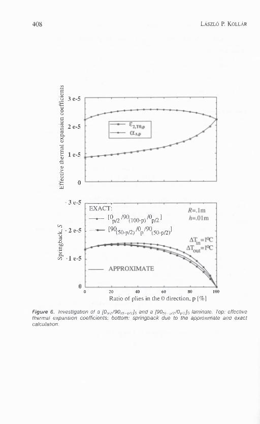
First, symmetric, cross ply cylindrical segments were investigated. The dataare plotted as a function of the percentage of zero direction plies. (The zero direc-tion is parallel to the axis of the cylinder.) In the approximate calculation for sym-metric laminates, the layup has no effect on the deformations; only the ratio of thezero to ninety direction plies affects the effective thermal expansion coefficients(see the top of Figure 6). The springback [Equation (38)] of the segments areshown in the bottom of Figure 6. The approximate value is the difference betweenthe thermal expansion coefficients plotted at the top of the figure. Using the platesolution, the calculated springback is zero. The exact calculations were per-formed for two extreme cases, first, if all the zero direction plies are in the mid-dle of the laminate, second, if all the zero plies are at the two outer surfaces ofthe laminate.
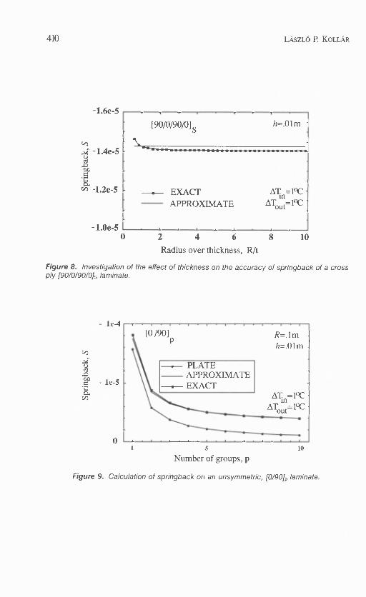
The springback of symmetric angle ply laminates is investigated in Figure 7.Figure 8 shows the effect of the radius/thickness ratio on the springback for a
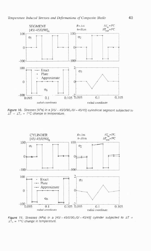
symmetric cross ply segment.Unsymmetric cross ply laminates were investigated in Figure 9.In Figures 10 and 11 the stresses for a cylindrical segment and for a closed
cylinder are given. In both cases the ratio of the radius to the thickness is ten andthe layup is [45/ — 45/0/90 2/0/ — 45/45].
In all the above cases we found good agreement between the exact and approx-imate calculations. (cr3 is not predictable by the approximate calculation, but thisstress is much smaller than a, and a2.)
7.2 Cylindrical Segments Subjected to Linear Change in Temperature
In the following examples symmetric composite cylindrical segments are con-sidered. The radius is 0.1 m and the thickness is 0.01 m in every case. The seg-ments are subjected to linear change in temperature, AT = z, the inner surfaceis cooled down by 0.005°C, the outer is heated up by 0.005°C.
Figure 12 shows the calculated springback of cross ply segments. There is
408 LASZLÓ P. KOLLAR
3 e-5
UUO
.7, 2 e-5crsra.a.)
1 e-5
O.0
LTJ
- 3 e 5
- 2 e-5UcC
au>
v -1e-5
00
20 40 60 80
100
Ratio of plies in the 0 direction, p [%1
Figure 6. Investigation of a (0,/2/9050-pids and a [9050 -p/2 /0p/2h laminate. Top: effectivethermal expansion coefficients; bottom: springback due to the approximate and exactcalculation.

Temperature Induced Stresses and Deformations of Composite Shells 409
3 e 5U
8UU
O• 2 e-5
Ca.
1 e-5
-3 e 5
-2 e-5C.)cZ
.1ZOA
cl)• -1 e-5
0
APPROXIMATE
R=.1mh=.01m
--.-- EXACT
ATout 1°C .
30 60
90
Direction of the plies, 4) [0]
Figure 7. Investigation of a [0 – Ns laminate. Top: effective thermal expansion coeffi-cients; bottom: springback due to the approximate and exact calculation.
[90/0/90/0] s h=.01m
--.— EXACT
ATin=1°C - APPROXIMATE
AT0=1°C
le-4
0
[0 /90] R=. lm •h=.01m .
—.— PLATE APPROXIMATE
EXACTAT =1°Ciu
ATout=1°C
410
LAszLO P. KOLLAR
-1.6e 5
-1.4e-50ao
C4C4 -1.2e-5
-1.0e-50 2 4 6
8
10
Radius over thickness, R/t
Figure 8. Investigation of the effect of thickness on the accuracy of springback of a crossply /90/0/90/0/s laminate.
5
10
Number of groups, p
Figure 9. Calculation of springback on an unsymmetric, [0/90], laminate.
02
•
SEGMENT[45/-45/0/90]s
100
-100
R=.1m ATn=1°C
h=.01m ATout=1°C
100
100
0.1radial coordinate
0.105
100 — Exact— Plate— Approximate
66
-1000 095
0.1radial coordinate
CYLINDER[45/-45/0/90/s
100
— Exact— Plate- Approximat
06
-100 0 095 0.1
radial coordinate
61
-100
100
R=.1mh=.01m
100 02
ATi=1°CAT =1°Cout
100
0.1radial coordinate
Temperature Induced Stresses and Deformations of Composite Shells 411
Figure 10. Stresses (kPa) in a [45/-45/0/90 2/0/-45/45] cylindrical segment subjected toAT = AT° = 1°C change in temperature.
Figure 11. Stresses (kPa) in a [45/ – 45/0/902/0/ – 45/45] cylinder subjected to AT =AT° = 1°C change in temperature.

190(50-p/2) /Up/90
(50-p/2)1
[0p/2
/90(1 00-P)
/0Pa
]
AT =-.005°Cin
'aJout=.°°5cC
0
— Exact— Plate— Approximate
6306
WI?
SEGMENT[45/-45/0/90ls
R=.1mh=.01m
0.4
0
4Ti0=-.005 CATout=-.005qC
-10.3
0
-0.3
412
LASZLO P. KOLLAR
3e 6
0 20 40 60 80 100
Ratio of plies in the 0 direction, p [%]
Figure 12. Investigation of the springback of 10p/2/90100- p/ZIS and of [90loo- p/2/0p/2 ]s lami-nates subjected to linear change in temperature. The results from the exact, approximate,and plate calculations are on the top of each other.
practically no difference between the results obtained by the exact, approximateand plate calculations.
The stresses of a [45/ — 45/0/90 2 /0/ — 45/45] cylindrical segment subjected to alinear change in temperature are given in Figure 13. The stresses (except a3) dueto the exact and approximate calculation are practically identical, the results fromthe plate solution are also very close.
0.095
0.1
0.105 0.095 0.1
0.105radial coordinate radial coordinate
Figure 13. Stresses (kPa) in a [45/-45/0/902/0/-45/45] cylindrical segment subjected tolinear change in temperature.
0
1
06
0.095 0.1radial coordinate
(113
-.0000.105 0.095 0.1
radial coordinate
0.105
SEGMENT[01s
2
0
2
.000
0
al
— Exact- Plate— Approximate
Temperature Induced Stresses and Deformations of Composite Shells 413
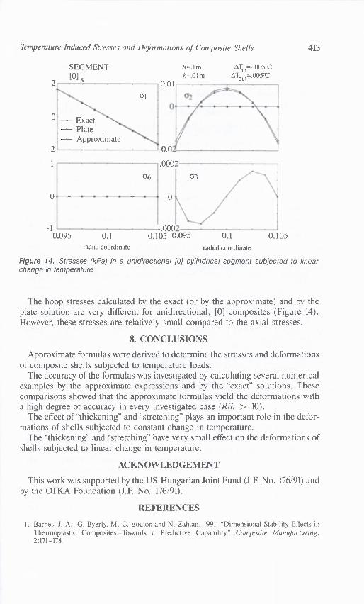
Figure 14. Stresses (kPa) in a unidirectional [0] cylindrical segment subjected to linearchange in temperature.
The hoop stresses calculated by the exact (or by the approximate) and by theplate solution are very different for unidirectional, [0] composites (Figure 14).However, these stresses are relatively small compared to the axial stresses.
8. CONCLUSIONS
Approximate formulas were derived to determine the stresses and deformationsof composite shells subjected to temperature loads.
The accuracy of the formulas was investigated by calculating several numericalexamples by the approximate expressions and by the "exact" solutions. Thesecomparisons showed that the approximate formulas yield the deformations witha high degree of accuracy in every investigated case (R/h > 10).
The effect of "thickening" and "stretching" plays an important role in the defor-mations of shells subjected to constant change in temperature.
The "thickening" and "stretching" have very small effect on the deformations ofshells subjected to linear change in temperature.
ACKNOWLEDGEMENT
This work was supported by the US-Hungarian Joint Fund (J.F. No. 176/91) andby the OTKA Foundation (J.F. No. 176/91).
REFERENCES
1. Barnes, J. A., G. Byerly, M. C. Bouton and N. Zahlan. 1991. "Dimensional Stability Effects inThermoplastic Composites—Towards a Predictive Capability," Composite Manufacturing,2:171-178.
414
LAszLO P. KOLLAR
2. Zahlan, N. and J. M. O'Neill. 1989. "Design and Fabrication of Composite Components; theSpring-Forward Phenomenon," Composites, 20:77-81.
3. Radford, D. W. and R. J. Diefendorf. 1990. "Shape Instabilities in Composites Resulting fromLaminate Anisotropy," Japan US Conference, Maui, HI, pp. 439-448.
4. Hamamoto, A. and W. T. Chang. 1990. "Deformation of Composite Box Beam Walls duringCure," Japan US Conference, Maui, HI, pp. 476-485.
5. Nelson, R. H. 1989. "Prediction of Dimensional Changes in Composite Laminates during Cur-ing," 34th International SAMPE Symposium, pp. 2397-2410.
6. Spencer, A. J. M., P. Watson and T. G. Rogers. 1991. "Mathematical Analysis of Springback Ef-fect in Laminated Thermoplastic Channel Sections," Composite Manufacturing, 2:253-258.
7. Roy, A. K. and S. W. Tsai. 1988. "Design of Thick Composite Cylinders," Journal of PressureVessel Techniques, ASME, 110:255-262.
8. Roy, A. K. 1991. "Response of Thick Laminated Composite Rings to Thermal Stresses," Compos-ite Structures, 18:125-138.
9. Kollar, L. P. and G. S. Springer. 1992. "Stress Analysis of Anisotropic Laminated Cylinders andCylindrical Segments," International Journal of Solids and Structures, 29:1499-1517.
10. Kollar, L. P., J. M. Patterson and G. S. Springer. 1992. "Composite Cylinders Subjected toHygrothermal and Mechanical Loads," International Journal of Solids and Structures, 29:1519-1534.
11. Kollar, L. P. and J. M. Patterson. 1993. "Composite Cylindrical Segments Subjected to Hygro-thermal and Mechanical Loads," submitted to the International Journal of Solids and Structures.
12. Noor, A. K., W. S. Burton and J. M. Peters. 1991. "Assessment of Computational Models forMultilayered Composite Cylinders," International Journal of Solids and Structures, 27:1269-1286.
13. Tsai, S. W. 1988. Composite Design (4th Edition). Dayton: Think Composites.14. Doxsee, L. E., Jr., W. I. Lee and G. S. Springer. 1985. "Temperature and Moisture Induced
Deformations in Composite Sandwich Panels," Journal of Reinforced Plastic and Composites,4:326-353.
15. Barnes, J. A., I. J. Simms, G. J. Farrow, D. Jacson, G. Wostenholm and B. Yates. 1990. "ThermalExpansion Behaviour of Thermoplastic Composite Materials," Journal of Thermoplastic Com-posite Materials, 3:66-80.
16. Fliigge, W. 1973. Stresses in Shells (2nd Edition). Berlin, etc.: Springer.17. Timoshenko, S. P. and J. M. Gere. 1961. Theory of Elastic Stability (2nd Edition). New York,
etc.: McGraw-Hill.18. Pagano, N. J. 1974. "Thickness Expansion Coefficients of Composite Laminates," Journal of
Composite Materials, 8:310-312, 1269-1286.