Applying Science to Cold Flow and Shrinkage Porosity...Applying Science to Cold Flow and Shrinkage...
37
Applying Science to Cold Flow and Shrinkage Porosity Graham Wilson
Transcript of Applying Science to Cold Flow and Shrinkage Porosity...Applying Science to Cold Flow and Shrinkage...

Applying Science to Cold Flow
and Shrinkage Porosity
Graham Wilson

Die Casting Rejects
• Most rejects are self-inflicted
• They have been designed into the process
• They can be designed out of the process
• Typical reject rates are 4% to 10%, or more
• 4% is 40,000 parts per million (ppm)
• 10% is 100,000 parts per million (ppm)
• This is an extraordinary amount of waste

Die Casting Rejects
• A more acceptable reject rate might be 0.5%
• This is still 5000 ppm
• The target reject rate should be 0.005%
• This is 50 ppm
• This target should exclude start-up rejects
• To minimise start-up rejects, the process must run 24 hours per day for the whole batch

Table of Causes
Most companies spend too much time and effort on the Operational Factors.
They would get better results if they spent more time and effort on the Design and Development Factors.
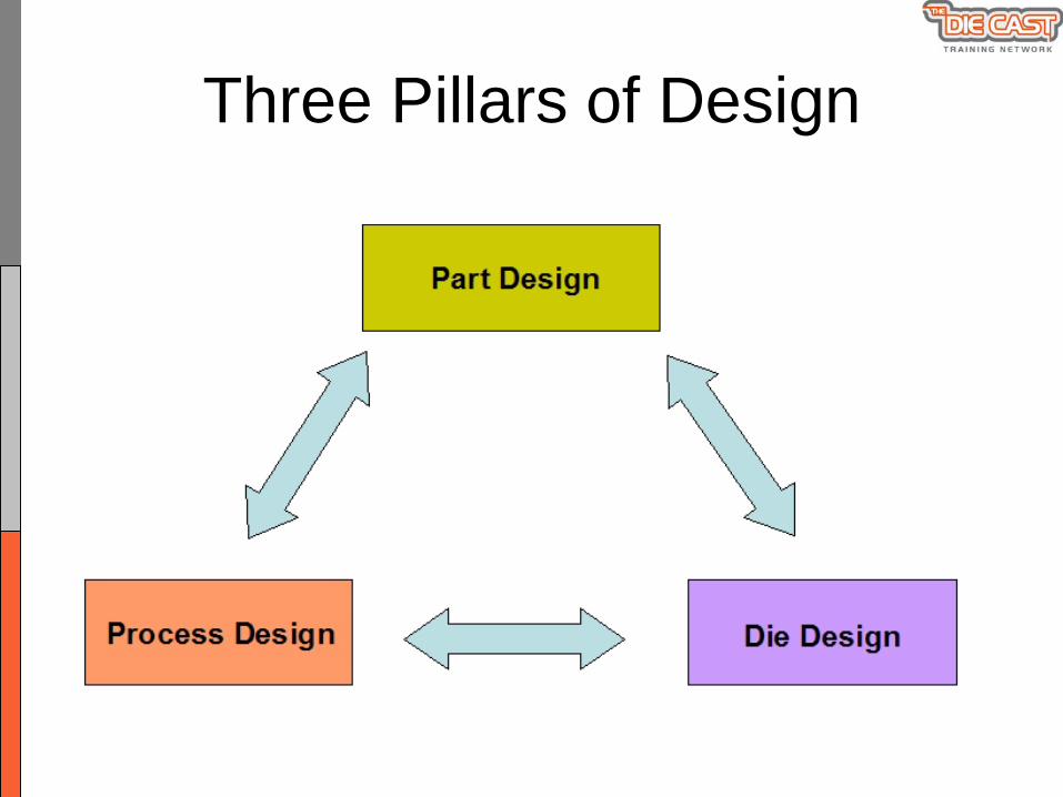
Three Pillars of Design

Some Objectives of Process Design
1. To ensure that the casting process can meet the specifications of the customer and the application of the component.
2. To align the process parameters with the required properties of the casting.
3. To design a process that will not produce rejects.
4. To minimise the total manufacturing cost of the component.

High Pressure Die Casting
• Venting Phase• Cavity Filling Phase• Solidification Phase• Ejection Phase
Cold Flow
Shrinkage Porosity
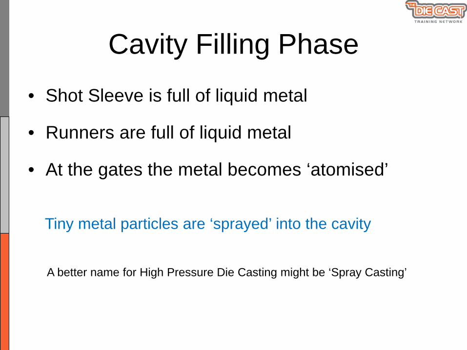
Cavity Filling Phase
• Shot Sleeve is full of liquid metal
• Runners are full of liquid metal
• At the gates the metal becomes ‘atomised’
Tiny metal particles are ‘sprayed’ into the cavity
A better name for High Pressure Die Casting might be ‘Spray Casting’
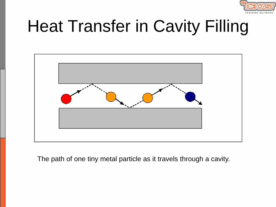
Heat Transfer in Cavity Filling
The path of one tiny metal particle as it travels through a cavity.

Heat Transfer in Cavity Filling
The path of another tiny metal particle as it travels through a cavity.

At the Instant of Cavity Fill
Some particles are still liquid
Some particles have solidified
This defines the parameter known as ‘the percentage of solids’

Cold Flow
A series of spotty marks or streaks on the surface of the casting.
Zinc alloy castings are particularly susceptible to cold flow.

Generic Cause of Cold FlowAn excessive amount of solidified metal particles forming while the cavity is being filled.
These particles clump together and block the path of other particles being sprayed into the cavity.
The result is the typical surface defect patterns known as ‘cold flow’.
Cold Flow is therefore directly related to the parameter known as ‘the percentage of solids at the instant of cavity fill’.
It is also related to the defects known as ‘short shots’, ‘incomplete fill’ and ‘misruns’.
Determining the Percentage of Solids
• It cannot be measured directly
• It can only be determined indirectly
• It can be calculated and predicted
• It is an important parameter in Process Design

Parameters which affect the % Solids
• Metal Temperature - Ti (º C)
• Die Temperature - Td (º C)
• Cavity Fill Time - t ( seconds)
• Wall Thickness - x (mm)
• Alloy and Die Steel properties
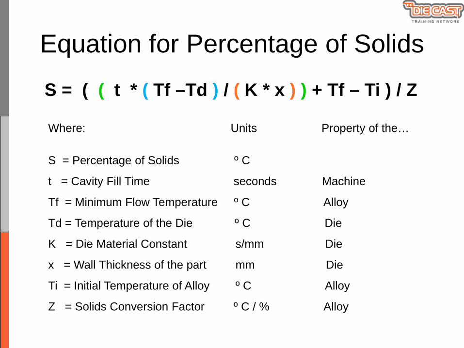
Equation for Percentage of Solids
S = ( ( t * ( Tf –Td ) / ( K * x ) ) + Tf – Ti ) / Z
Where: Units Property of the…
S = Percentage of Solids º C
t = Cavity Fill Time seconds Machine
Tf = Minimum Flow Temperature º C Alloy
Td = Temperature of the Die º C Die
K = Die Material Constant s/mm Die
x = Wall Thickness of the part mm Die
Ti = Initial Temperature of Alloy º C Alloy
Z = Solids Conversion Factor º C / % Alloy

Grouping the Parameters

Minimum Flow Temperature (Tf)
Alloy Tf ° CMg 510Al: 360, 380, 384 570Al: 390 595Zn: 3, 5, 7 382Zn: 12, 27 445Cu: 60/40 900Cu: 85-5-5-5 930Pb: 280

The Die Material Factor (K)
Die Material For Alloys of.... Value of K (s/mm )
P20 Steel Zn 0.0312
Pb 0.0156
H13 or H21 Steel Al, Zn, Mg, Brass 0.0346
Pb 0.0173
Tungsten Zn, Mg, Al, Brass 0.0124

Solids Conversion Factor (Z)
Alloy Z ° C / %
Mg 2.5
Al 3.8
Zn: 3, 5, 7 2.5
Zn: 12, 27 3.2
Cu 4.7
Pb 2.1

Worked Example 1: Zn Alloy 3
Wall Thickness: 1.0 mm
Metal Temperature: Ti = 420 ºC
Die Temperature: Td = 180 ºC
Cavity Fill Time: t = 18 ms = 0.018 sDie Steel: H13
Alloy: ZA3
From the tables:
Die Material Factor: K = 0.0346
Minimum Flow Temp: Tf = 382 ºC
Solids Conversion Factor: Z = 2.5 ºC/%
S = ( ( t * ( Tf –Td ) / ( K * x ) ) + Tf – Ti ) / Z S = (( 0.018 * (382-180) / (0.0346 * 1)) + 382 – 420 ) / 2.5
S = (105 + 382 -420) / 2.5
S = 26.8 %

Worked Example 2: Zn Alloy 3
Wall Thickness: 1.0 mm
Metal Temperature: Ti = 420 ºC
Die Temperature: Td = 200 ºC
Cavity Fill Time: t = 10 ms = 0.010 sDie Steel: H13
Alloy: ZA3
From the tables:
Die Material Factor: K = 0.0346
Minimum Flow Temp: Tf = 382 ºC
Solids Conversion Factor: Z = 2.5 ºC/%
S = ( ( t * ( Tf –Td ) / ( K * x ) ) + Tf – Ti ) / Z S = (( 0.010 * (382-200) / (0.0346 * 1)) + 382 – 420 ) / 2.5
S = (52 + 382 -420) / 2.5
S = 5.6 %

Rule of Thumb for % Cold FlowFor zinc based Die Cast parts, a good rule of thumb is that the percentage of the surface area of a casting which displays cold flow is two times the percentage of solids.
% Cold Flow = 2 * Percentage of Solids at Cavity Fill
Worked example 1: Cold Flow % = 26.8 * 2 = :53.6 %
Worked example 2: Cold Flow % = 5.6 * 2 = :11.2 %

Worked Example 3: Aluminium
Wall Thickness: 3.2 mm
Metal Temperature: Ti = 670 ºC
Die Temperature: Td = 240 ºC
Cavity Fill Time: t = 47 ms = 0.047 sDie Steel: H13
Alloy: CA313
From the tables:
Die Material Factor: K = 0.0346
Minimum Flow Temp: Tf = 570 ºC
Solids Conversion Factor: Z = 3.8 ºC/%
S = ( ( t * ( Tf –Td ) / ( K * x ) ) + Tf – Ti ) / Z S = (( 0.047 * (570-240) / (0.0346 * 3.2)) + 570 – 670 ) / 3.8
S = (139 + 570 -670) / 3.8
S = 10.2 %

% Solids Guidelines for Cold Flow
% Solids Cold Flow Severity and Casting Application
0 % Cold Flow eliminated.
Required for electroplated castings and A1 surface finish
1 - 5 % A small amount of cold flow will be present
May be OK for powder coating, or castings which are not highly visible.
6 – 10 % A lot of cold flow will be present.
May still be OK for unseen castings.
11 – 25 % Extensive cold flow on the castings.

Cold Flow Summary
• The % Solids at cavity fill is an important Process Parameter
• It should be calculated in the Process Design stage
• The % Solids is directly related to the amount of Cold Flow on the casting
• The % Solids also affects the Shrinkage Porosity inside the casting

Shrinkage PorositySolidification begins at the die surface
A thin, dense layer forms on the surface of the casting
The inside of the casting is still liquid
Die
Die

Shrinkage PorosityAluminium shrinks about 8% by volume as it solidifies
Small voids appear in the liquid metal near the centre
The voids are created by the direction and sequence of the solidification
Die
Die
They reach maximum size when solidification is complete

% Solids and Shrinkage
If the percentage of Solids is zero, all of the metal particles in the above diagram will be red. They will all be in the liquid state.
Therefore the maximum shrinkage will occur as it solidifies, say 8%
Therefore all the metal in the cavity will be subject to shrinkage.

% Solids and Shrinkage
The shrinkage that occurs will therefore be reduced by 30%.
If the percentage of solids is 30%, then 30% of the particles will have already solidified when the cavity is full.
So, instead of 8% shrinkage, it becomes 5.6%.

% Solids and Shrinkage
If the percentage of solids is increased to 50%, then the shrinkage which occurs will be reduced by 50%.
So, instead of 8% shrinkage, it becomes 4%.
This will have a significant effect on the amount, and the size, of shrinkage porosity in the parts.

The Process Design Challenge
• Increasing the % Solids decreases the shrinkage in the parts
• However, the Cold Flow will increase• The process design might have choose a
compromise• Thin walled zinc castings are more concerned
with Cold Flow• Thick Al castings usually focus on shrinkage

Eliminating Shrinkage Porosity
• Increasing the % Solids will not eliminate shrinkage porosity rejects
• This must be done by controlling the heat flow paths through the tool steel
• However, increasing the % Solids will assist, by reducing the amount of shrinkage that takes place during the solidification phase

Summary
• The % Solids at cavity fill is an important Process Parameter
• It should be calculated in the Process Design stage
• The % Solids is directly related to the amount of Cold Flow on the casting
• The % Solids also affects the Shrinkage Porosity inside the casting
Acknowledgements
• E.A. Herman for his series of text books on Die Casting Die and Process Design, for both NADCA and ADCA
• The Die Cast Training Network for images and text from the online training subjects

Further Learning
• You can continue your learning about these aspects of the Die Casting process online at the following website:
• www.diecasttraining.net
• ADCA is planning more in-depth seminars on these topics in 2017 and beyond.

The End