Applying Open Architecture Concepts to Mission and … · Applying Open Architecture Concepts to...
21
Applying Open Architecture Concepts to Mission and Ship Systems John M. Green Gregory Miller Senior Lecturer Lecturer Department of Systems Engineering
Transcript of Applying Open Architecture Concepts to Mission and … · Applying Open Architecture Concepts to...
Applying Open Architecture Concepts to Mission and Ship Systems
John M. Green Gregory MillerSenior Lecturer Lecturer
Department of Systems Engineering

2
Introduction
• Purpose: to introduce a simulation based methodology to facilitate development of a software product line architecture concept for the Navy’s C5ISR systems.
• Two key advantages to the proposed methodology:1. it provides a formal systems approach to the verification of the product
line architecture requirements consistent with the Department ofDefense Architecture Framework.
2. it provides a medium for the iterative development of architectures that blend the operational concepts of FORCEnet with the system and technical imperatives of Open Architecture and Services-Oriented Architecture (SOA).
C2 GridC2 Grid
Sensor GridSensor Grid
Engagement GridEngagement Grid
3
What I’m Going to Tell You
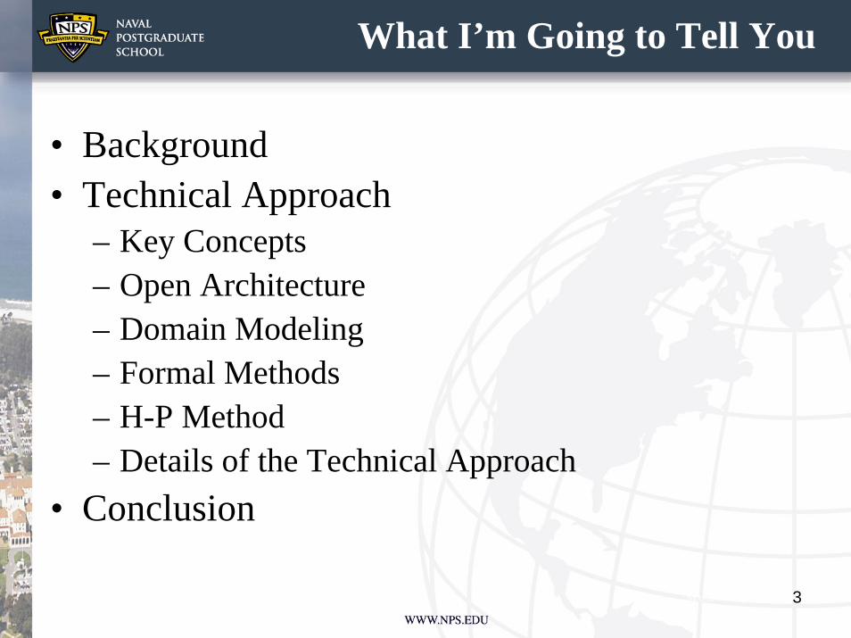
• Background• Technical Approach
– Key Concepts– Open Architecture– Domain Modeling– Formal Methods– H-P Method– Details of the Technical Approach
• Conclusion

4
Background
• The last 15 years (or thereabouts) has seen a number of interesting developments in the technologies that support C4ISR system development. – For example, the advent of CEC and GPS provided the impetus for the
conceptual development of Network-Centric Warfare (NCW), Network-Centric Operations (NCO) and FORCEnet [Alberts, Garstka, and Stein 2000].
– Yet, despite all that has been written about the concepts of FORCEnet and Open Architecture (OA), there has been little written on how these two concepts will come together in the naval C4ISR systems of the future.
• The main emphasis has been on technologies such as InternetProtocol version 6 (IPv6), not the architecture.
• As a result, there is no commonly shared or understood model of what this end state may look like.

5
More Background
• There is a tendency to view the system architecture using existing paradigms that were used to develop the “stove-piped” systems that are now proving to be limited in their capability.
• This is a “paving the cow paths”approach and has made developing FORCEnet capable systems difficult.
• European firms such as Thales, Saabtech and Terma have already validated the concepts of open architecture, software product lines, and software reuse as applied to combat systems

6
Key Concepts
• In addition to lessons learned from European firms, the proposed Technical approach is built upon lessons learned from Lockheed Martin’s Norwegian Frigate Project and a predecessor program, Taiwan’s PFG-2 Class Frigate project
• Valuable lessons were also learned from the predecessor program to OA, the Common Command and Decision (Common C&D) project.
• Common C&D resulted in the development of several FORCEnet related concepts that were briefed to the Assistant Secretary of the Navy for Research and Development.

7
OA Principles
• The key Open Architecture principles espoused by the Navy are [Naval OA Strategy]:– Modular design and design disclosure– Reusable application software– Interoperable joint warfighting applications and secure information
exchange– Life-cycle affordability– Encouraging competition and collaboration through development of
alternative solutions and sources• The first two principles are especially relevant to this paper. It
is the authors’ belief that proper attention to these principleswill result in software product lines that provide domain specific solutions.

8
The Details of the Technical Approach
• The ability to make good design decisions early in the process is a significant driver in effectively lowering life-cycle cost and system development time.
• There are two key issues to be addressed with the use of the Open Architecture concept:– What is the structure of the various product lines
required to support the various warfare domains, and
– What is the technical approach?
9
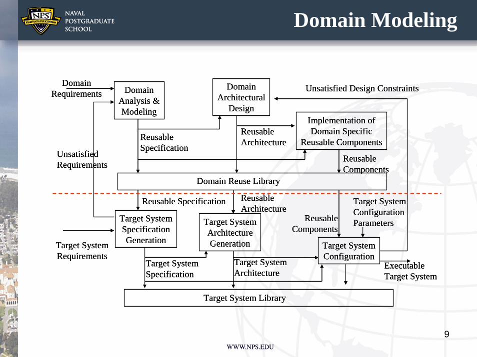
Domain Modeling
DomainAnalysis &Modeling
DomainArchitectural
DesignImplementation ofDomain Specific
Reusable Components
Domain Reuse Library
Target SystemSpecificationGeneration
Target System Library
DomainRequirements
Target SystemRequirements
ReusableSpecification
ReusableArchitecture
ReusableComponents
Unsatisfied Design Constraints
Unsatisfied Requirements
Target SystemArchitectureGeneration Target System
Configuration
Reusable Specification ReusableArchitecture
Target SystemSpecification
Target SystemArchitecture
ExecutableTarget System
ReusableComponents
Target SystemConfigurationParameters
10
Formal Methods
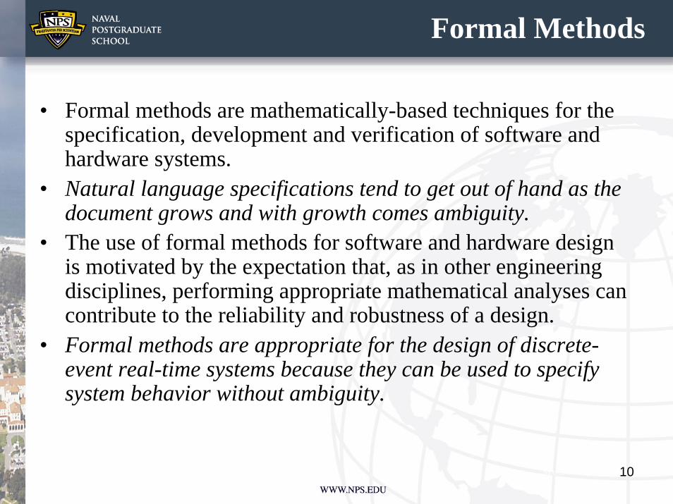
• Formal methods are mathematically-based techniques for the specification, development and verification of software and hardware systems.
• Natural language specifications tend to get out of hand as the document grows and with growth comes ambiguity.
• The use of formal methods for software and hardware design is motivated by the expectation that, as in other engineering disciplines, performing appropriate mathematical analyses can contribute to the reliability and robustness of a design.
• Formal methods are appropriate for the design of discrete-event real-time systems because they can be used to specify system behavior without ambiguity.
11
The Approach
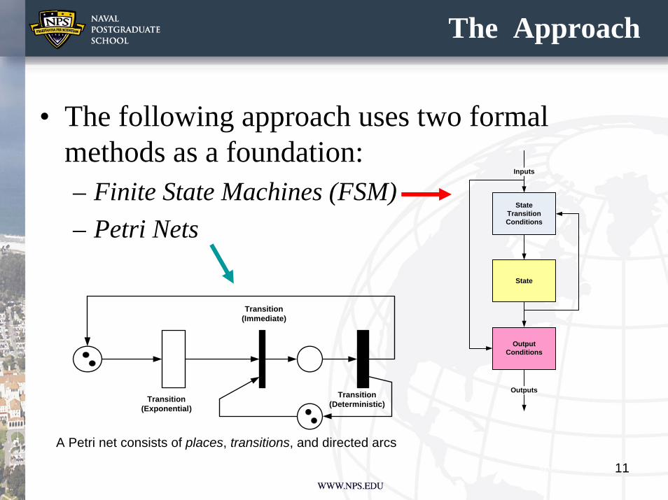
• The following approach uses two formal methods as a foundation: – Finite State Machines (FSM)– Petri Nets
State
OutputConditions
Outputs
Inputs
StateTransitionConditions
Transition(Immediate)
Transition(Exponential)
Transition(Deterministic)
A Petri net consists of places, transitions, and directed arcs

12
The Methodology
• Centered around the Hatley-Pirbhai “Process for Systems Architecture and Requirements Engineering” (PSARE)– Model-based process that uses FSM & Petri Nets– Accommodates HW, SW & PW– Can be described using SYSML/UML or EFFBD’s (to
name two) (not tool dependent)– Results in both a functional and architectural specification
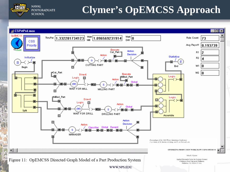
model– Can be captured with Clymer’s OpEMCSS modeling
approach which represents both FSM and Petri Nets• Core elements are the process/control model and the
architecture templateOperational Evaluation Modeling for Context Sensitive Systemshttp://www.ecs.fullerton.edu/~jclymer/

13
Hatley-Pirbhai Process/Control Model
Process Model
Control Model
ProcessActivators
DataConditions
Input ProcessedOutput
ControlOutputs
ControlInputs
DecisionTable
EventLogic 2
ActionLogic
StateTransitionDiagram
EventLogic 1
List ofInternalSignals
List ofInternalSignals
List ofEventsList of
Events
List ofActions
List ofInput
Signals
List ofInput
Signals
14
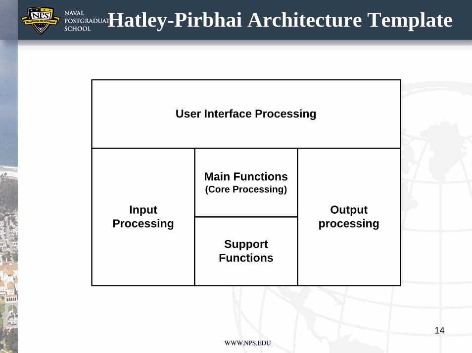
Hatley-Pirbhai Architecture Template
User Interface Processing
Main Functions(Core Processing)
Outputprocessing
InputProcessing
Support Functions

15
H-P Overview
The steps
The elements
Figures used with permission from H&A Systems Engineeringhttp://www.hasys.com/
H-P originally used Yourdon-DeMarco
notation

16
Allocating to HW, SW & PWAllocating to HW, SW & PW
Figure used with permission from H&A Systems Engineeringhttp://www.hasys.com/
17
Clymer’s OpEMCSS Approach

18
H-P Advantages
Figure used with permission from H&A Systems Engineeringhttp://www.hasys.com/
19
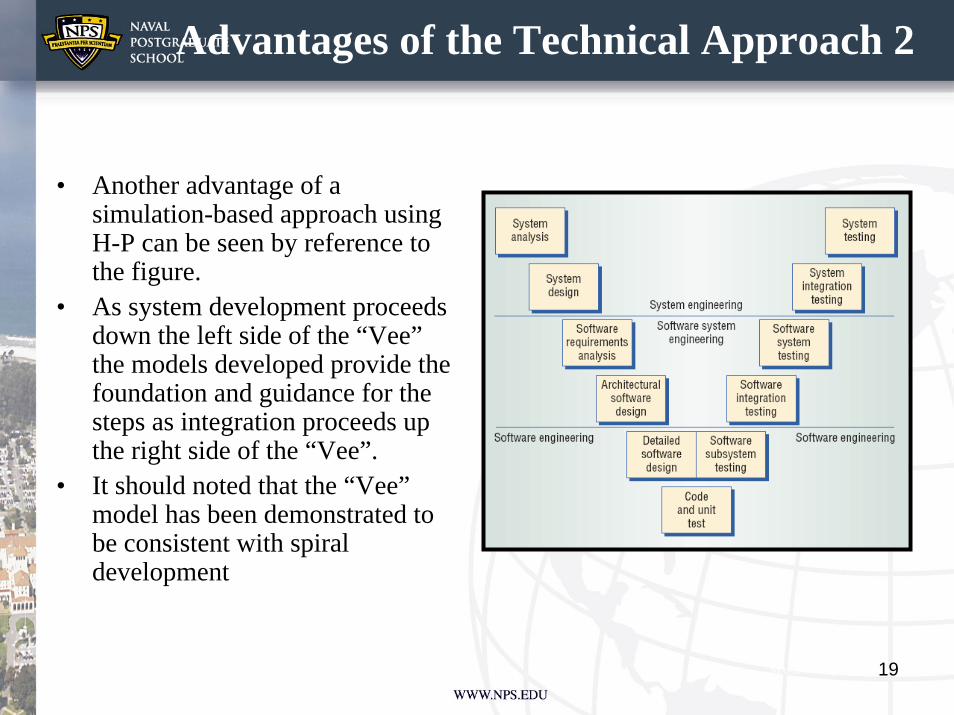
Advantages of the Technical Approach 2
• Another advantage of a simulation-based approach using H-P can be seen by reference to the figure.
• As system development proceeds down the left side of the “Vee” the models developed provide the foundation and guidance for the steps as integration proceeds up the right side of the “Vee”.
• It should noted that the “Vee” model has been demonstrated to be consistent with spiral development

20
Conclusion• The presented work gives emphasis to the value of a formal process in
architecture development. • In this case formal will mean that the architecture requirements will be
validated through the use of simulation as part of a defined methodology as described.
• Specifically, the model driven architecture approach has the following advantages:
– It is a formal method for tying the architecture requirements process to the architecture verification process.
– It is consistent with acquisition policy– It provides a methodology to test Network Centric Operations concepts such as
MDA, CMD, and TCT. • The use of a simulation-based methodology will result in the requisite
DODAF artifacts required for both requirements capture and the description of the system functional behavior.
• In addition, it supports the development of architectures that incorporate modular design and the identification of reusable and interoperable modules/applications.
• This approach is consistent with the development of a capability/systems-based architecture using a spiral or “Vee” approach.
21
Future Work
• Incorporation of the use case paradigm• Mapping to DoDAF• Incorporation of Clymer’s work • Merging notations/languages into a universal
architecture descriptive framework