Applied Thermal Engineering - Yuwen...
10
Research Paper Cumulative effects of using pin fin heat sink and porous metal foam on thermal management of lithium-ion batteries Shahabeddin K. Mohammadian, Yuwen Zhang ⇑ Department of Mechanical and Aerospace Engineering, University of Missouri, Columbia, MO 65211, USA highlights 3D transient thermal analysis of a pouch Li-ion cell has been carried out. Using pin fin heat sink improves the temperature reduction at low pumping powers. Using pin fin heat sink enhances the temperature uniformity at low air flow rates. Porous aluminum foam insertion with pin fins improves temperature reduction. Porous aluminum foam insertion with pin fins enhances temperature uniformity. article info Article history: Received 22 October 2016 Revised 30 January 2017 Accepted 28 February 2017 Available online 3 March 2017 Keywords: Lithium-ion battery pack Thermal management Pin fin heat sink Porous metal foam Hybrid electric vehicles abstract Three-dimensional transient thermal analysis of an air-cooled module was carried out to investigate cumulative effects of using pin fin heat sink and porous metal foam on thermal management of a Li- ion (lithium-ion) battery pack. Five different cases were designed as Case 1: flow channel without any pin fin or porous metal foam insertion, Case 2: flow channel with aluminum pin fins, Case 3: flow channel with porous aluminum foam pin fins, Case 4: fully inserted flow channel with porous aluminum foam, and Case 5: fully inserted flow channel with porous aluminum foam and aluminum pin fins. The effects of porous aluminum insertions, pin fin types, air flow inlet temperature, and air flow inlet velocity on the temperature uniformity and maximum temperature inside the battery pack were systematically investi- gated. The results showed that using pin fin heat sink (Case 2) is appropriate only for low air flow veloc- ities. In addition, the use of porous aluminum pin fins or embedding porous aluminum foam inside the air flow channel (Cases 3 and 4) are not beneficial for thermal management improvement. The combination of aluminum pin fins and porous aluminum foam insertion inside the air flow channel (Case 5) is a proper option that improves both temperature reduction and temperature uniformity inside the battery cell. Ó 2017 Elsevier Ltd. All rights reserved. 1. Introduction The climate change is mostly resulted in from burning fossil fuels which threatens human health and the balance of the ecosys- tem. Many researchers are looking for ways to replace fossil fuels through new energy transportation technology for hybrid electric vehicles—some of which will use rechargeable batteries. Lithium ion (Li-ion) batteries have high energy density and are not subject to the memory effect [1]. These batteries are one of the best candi- dates for clean energy transportation. However, heat generation inside the Li-ion batteries during charge and discharge processes increases their temperature. This rise in temperature reduces their reliability and subjects them to the danger of thermal runaway. Therefore, thermal management is crucial to ensure thermal stabil- ity and long-term durability of Li-ion batteries. Among the many different kinds of thermal management sys- tems, air cooling has attracted the attention of many researchers due to its simplicity. Fan et al. [2] studied an air-cooled Li-ion bat- tery pack computationally. They decreased the maximum temper- ature rise by increasing the air flow rate and lowering the gap spacing. They also showed that for the same gap spacing and air- flow rate, two-side cooling is more effective than one-side cooling. A simple modeling methodology that describes thermal behavior of an air-cooled Li-ion battery system was proposed by Choi and Kang [3]. Their model can simulate convective heat transfer cooling during battery operation accurately. Battery thermal behavior and design parameters were exam- ined by Karimi and Li [4] using natural convection, forced convec- tion, and phase change materials (PCM) cooling methods. Their http://dx.doi.org/10.1016/j.applthermaleng.2017.02.121 1359-4311/Ó 2017 Elsevier Ltd. All rights reserved. ⇑ Corresponding author. E-mail address: [email protected] (Y. Zhang). Applied Thermal Engineering 118 (2017) 375–384 Contents lists available at ScienceDirect Applied Thermal Engineering journal homepage: www.elsevier.com/locate/apthermeng
Transcript of Applied Thermal Engineering - Yuwen...

Applied Thermal Engineering 118 (2017) 375–384
Contents lists available at ScienceDirect
Applied Thermal Engineering
journal homepage: www.elsevier .com/locate /apthermeng
Research Paper
Cumulative effects of using pin fin heat sink and porous metal foam onthermal management of lithium-ion batteries
http://dx.doi.org/10.1016/j.applthermaleng.2017.02.1211359-4311/� 2017 Elsevier Ltd. All rights reserved.
⇑ Corresponding author.E-mail address: [email protected] (Y. Zhang).
Shahabeddin K. Mohammadian, Yuwen Zhang ⇑Department of Mechanical and Aerospace Engineering, University of Missouri, Columbia, MO 65211, USA
h i g h l i g h t s
� 3D transient thermal analysis of a pouch Li-ion cell has been carried out.� Using pin fin heat sink improves the temperature reduction at low pumping powers.� Using pin fin heat sink enhances the temperature uniformity at low air flow rates.� Porous aluminum foam insertion with pin fins improves temperature reduction.� Porous aluminum foam insertion with pin fins enhances temperature uniformity.
a r t i c l e i n f o
Article history:Received 22 October 2016Revised 30 January 2017Accepted 28 February 2017Available online 3 March 2017
Keywords:Lithium-ion battery packThermal managementPin fin heat sinkPorous metal foamHybrid electric vehicles
a b s t r a c t
Three-dimensional transient thermal analysis of an air-cooled module was carried out to investigatecumulative effects of using pin fin heat sink and porous metal foam on thermal management of a Li-ion (lithium-ion) battery pack. Five different cases were designed as Case 1: flow channel without anypin fin or porous metal foam insertion, Case 2: flow channel with aluminum pin fins, Case 3: flow channelwith porous aluminum foam pin fins, Case 4: fully inserted flow channel with porous aluminum foam,and Case 5: fully inserted flow channel with porous aluminum foam and aluminum pin fins. The effectsof porous aluminum insertions, pin fin types, air flow inlet temperature, and air flow inlet velocity on thetemperature uniformity and maximum temperature inside the battery pack were systematically investi-gated. The results showed that using pin fin heat sink (Case 2) is appropriate only for low air flow veloc-ities. In addition, the use of porous aluminum pin fins or embedding porous aluminum foam inside the airflow channel (Cases 3 and 4) are not beneficial for thermal management improvement. The combinationof aluminum pin fins and porous aluminum foam insertion inside the air flow channel (Case 5) is a properoption that improves both temperature reduction and temperature uniformity inside the battery cell.
� 2017 Elsevier Ltd. All rights reserved.
1. Introduction
The climate change is mostly resulted in from burning fossilfuels which threatens human health and the balance of the ecosys-tem. Many researchers are looking for ways to replace fossil fuelsthrough new energy transportation technology for hybrid electricvehicles—some of which will use rechargeable batteries. Lithiumion (Li-ion) batteries have high energy density and are not subjectto the memory effect [1]. These batteries are one of the best candi-dates for clean energy transportation. However, heat generationinside the Li-ion batteries during charge and discharge processesincreases their temperature. This rise in temperature reduces theirreliability and subjects them to the danger of thermal runaway.
Therefore, thermal management is crucial to ensure thermal stabil-ity and long-term durability of Li-ion batteries.
Among the many different kinds of thermal management sys-tems, air cooling has attracted the attention of many researchersdue to its simplicity. Fan et al. [2] studied an air-cooled Li-ion bat-tery pack computationally. They decreased the maximum temper-ature rise by increasing the air flow rate and lowering the gapspacing. They also showed that for the same gap spacing and air-flow rate, two-side cooling is more effective than one-side cooling.A simple modeling methodology that describes thermal behaviorof an air-cooled Li-ion battery system was proposed by Choi andKang [3]. Their model can simulate convective heat transfer coolingduring battery operation accurately.
Battery thermal behavior and design parameters were exam-ined by Karimi and Li [4] using natural convection, forced convec-tion, and phase change materials (PCM) cooling methods. Their
Nomenclature
A cross section area of the channel (m2)C inertial resistance (1/m)CF inertial coefficientCp specific heat (J/kg K)D viscous resistance (1/m2)E energyF Faraday numberh sensible enthalpyi discharge current of a Li-ion unit cell per unit volume
(A/m3)I discharge current (A)J distribution fluxk thermal conductivity (W/m2 K)K permeability (m2)_Q heat generation rate (W)_q internal heat generation rate per unit volume (W/m3)Ri internal equivalent resistance of unit volume (X/m3)p pressure (Pa)PCM phase change materialS!
source termShf fluid enthalpy source termSDT standard deviation of the temperature field inside the
battery (K)SOC state of charget discharge duration (h)T temperature (�C or K)
u velocity (m/s)U open-circuit voltage (V)_V volumetric flow rate (m3/s)V unit cell voltage (V)DS entropy change (J/mol K)
Greekq density (kg/m3)c porositym viscosity (kg/m s)v!
velocity vector (m/s)��s stress tensor
Subscriptave averageb batteryeff effectivef fluidH.S. heat sinkin inletmin minimummax maximumout outlets solid
376 S.K. Mohammadian, Y. Zhang / Applied Thermal Engineering 118 (2017) 375–384
distributed air cooling improved the temperature uniformity insidethe battery and enhanced the thermal performance of the batterypack. In another study, Karimi and Dehghan [5] investigated a Li-ion battery pack using different operating conditions. They founduniform temperature distribution as well as uniform voltage distri-bution inside the battery pack by considering more than one inletfor cooling fluid flow. In a similar study, Fathabadi [6] used dis-tributed thin ducts to cool the Li-ion battery pack and showed thatthe proposed battery pack satisfied all thermal and physical issuesrelated to vehicle battery packs. An air cooled active control bat-tery pack was studied by He et al. [7]. They reduced the energyconsumption required for cooling by combining air flow recipro-cating and active controlling. Mohammadian and Zhang [8]designed a special pin fin heat sink and showed that their aircooled thermal management module can improve temperatureuniformity inside the battery pack. Chen et al. [9] considered fourdifferent cooling methods and found that under their assumptionssimple air cooling needs more energy compare with direct liquidcooling, indirect liquid cooling, and fin cooling. A thermo-electro-chemical model for forced convection air cooled method was pro-posed by Tong et al. [10].
Combination of air cooling and porous metal foams is anotherform of cooling systems designed for Li-ion batteries. A metalfoam-based air-cooled thermal management system for high-capacity lithium-titanate batteries was fabricated by Giulianoet al. [11]. They showed that their air-cooled system is an effectivemethod for the thermal management of automotive battery packs.Mohammadian et al. [12] inserted aluminum porous metal foaminside the flow channels of an air-cooled Li-ion battery modulepartially and found significant thermal management improvement.On another study, Wang et al. [13] showed that using aluminumfoam enhanced the temperature uniformity of the PCM by speed-ing up the melting process and keeps the Li-ion battery in lowertemperature. Recently, Mohammadian and Zhang [14] utilizedthe combination of metal and non-metal foams for an air cooled
Li-ion battery module. They found that, partial use of ceramic foamas part of the heat sink combined with partial insertion of alu-minum foam in the air flow channel improves the temperatureuniformity of the battery significantly.
Liquid cooling is another cooling method that some researchersfollowed it. Liquid metals was used by Yang et al. [15] for a Li-ionbattery pack. Compare with water, lower temperature and highertemperature uniformity were obtained under the same flow condi-tions. Lan et al. [16] proposed a novel minichannel cooling methodand showed that this method reduced the maximum temperaturerise and improved temperature difference across the whole bat-tery. On another study Xu et al. [17] found that for a single cell,minichannel cooling cannot prevent thermal runaway. However,it can prevent battery fratricide due to thermal runaway propaga-tion between cells.
Some researchers have tried to improve the thermal manage-ment of the Li-ion batteries considering the shape of the batterypacks and the battery arrangements. Park [18] enhanced the cool-ing performance of an existing air-cooled battery module byemploying a tapered manifold and a pressure relief ventilation.Xu and He [19] showed that shortening the air flow path by chang-ing the battery arrangement from a longitudinal position to a hori-zontal position improves the heat dissipation performance of abattery pack. A design concept of a ‘‘Z-type” flow pack was identi-fied by Sun and Dixon [20]. They showed that the use of taperedinlet and outlet ducts reduces the variation of flow rates in the cool-ing channels. Thermal performance of a battery module under dif-ferent cell arrangements was investigated by Wang et al. [21], whodetermined that, the best cooling performance can be obtained byinstalling the fan on top of the module. They also concluded thata cubic arrangement was the most desired structure based on cool-ing costs, and a hexagonal structure was given as the optimalarrangement based on the space utilization of the battery module.Martín-Martín et al. [22] designed, build, and tested an improvedthermal management system of a li-ion battery module.

S.K. Mohammadian, Y. Zhang / Applied Thermal Engineering 118 (2017) 375–384 377
Since, temperature uniformity inside the Li-ion batteries has animportant role on the electrical performance of Li-ion batteries,some researchers have given it special attention. Thermal behaviorof flat-plate and cylindrical batteries was investigated by Xun et al.[23]. They found that temperature uniformity decreases byincreasing the cooling channel size. Liu et al. [24] showed that,even though the air was distributed by wedge-shaped plenums,the air flow distribution in the parallel cooling channels wasnon-uniform. Yu et al. [25] investigated an air cooled thermal man-agement system that contains two types of air ducts with indepen-dent intake channels and fans. They found that temperatureuniformity of the battery pack can be improved significantly. Inanother study, Mohammadian et al. [26] proposed a novel internalcooling method utilizing liquid electrolytes as the coolant. Theyshowed that their proposed internal cooling method improvesthe temperature uniformity inside the battery much better thanexternal cooling methods. Recently, Mohammadian and Zhang[27] investigated thermo-electrical effects of size of microchannelson an internally cooled Li-ion battery cell. They found that increas-ing the size of the microchannels improved the thermal perfor-mance of the battery cell and caused a bit decrease on the cellvoltage.
Constant height pin fin heat sinks are beneficial tools that havebeen utilized in many cooling systems. These heat sinks can reducethe overall temperature inside the battery significantly. However,they are unable to improve the temperature uniformity acceptably.Therefore, in this study aluminum foam were inserted inside theair flow channels of the heat sink to prepare a compatible thermalmanagement system for Li-ion batteries by improving the temper-ature uniformity. To be sure about the results, it was tried to inves-tigate different combinations of pin fins and aluminum foaminsertion.
In order to fulfill the requirement of the thermal managementfor Li-ion batteries that prepares a uniform temperature distribu-tion inside the battery pack (that improves the electrochemicalperformance of the battery cell) and prevents the battery packfrom thermal runaway, a three-dimensional transient thermalanalysis of an air-cooled module will be investigated (Fig. 1). Fivedifferent cases were studied by utilizing (1) solid or porous alu-minum pin fins, and (2) embedding porous aluminum foam insidethe air flow channel. The different cases are illustrated in Fig. 2. Toquantify the temperature uniformity inside the battery pack, Stan-dard Deviation of the Temperature field (SDT) will be utilized.Lower SDT leads to better temperature uniformity inside the bat-tery pack. Meanwhile, the maximum temperature inside the bat-tery pack (Tmax) will be investigated to prevent battery pack fromthermal runaway.
2. Mathematical model
To simplify the simulations and reduce costs, just one symmet-rical part of the battery pack was considered. The air flow channelheight and the thickness of the heat sink were 3 mm and 0.5 mm,respectively. Staggered arrangement with longitudinal and trans-verse pitch to diameter ratios of SL/d = 2 and ST/d = 1 was utilized.The diameter and heights of the pin fins were 2 mm and 3 mm,respectively. Boundary conditions are presented in Table 1. Thedimensions and properties of the pouch cell are in Table 2.
Heat generation inside the battery cells depends on the electro-chemical reaction rate. The correlation proposed by Bernardi et al.[28] was utilized to calculate heat generation in this study. This cor-relation has been derived from the thermodynamic energy balanceof a completecell. A simplified formof this correlation follows[4,29]:
_Q ¼ IðU � VÞ � I T@U@T
� �ð1Þ
where _Q , I, U, V, and T are the heat generation rate, electric currentpassing through the unit cell, open-circuit voltage of the unit cell,cell voltage, and the cell temperature, respectively. The first termof the right-hand side of Eq. (1) is the irreversible heat generationdue to charge-transfer over potentials at the interface, Ohmic lossesin the cell, and mass transfer limitations. The second term is rever-sible heat generation due to entropic changes [30]. In this study, itwas assumed that there is no mixing effects or phase change. Also, itwas assumed that only one electrochemical reaction occurs in thebatteries during normal operation, and thermal radiation isnegligible.
Eq. (1) can be reformulated as follow [4–6,31]:
_q ¼ Rii2 � iT
DSF
ð2Þ
where _q, Ri, i, ΔS, and F are the rate of internal heat generation perunit volume, internal equivalent resistance of the unit cell, dis-charge current of the Li-ion unit cell per unit volume, entropychange, and the Faraday number (96,485 C/mol), respectively. Theinternal equivalent resistance of a unit cell depends on both thetemperature and state of charge (SOC) of the battery and can bemeasured as shown below [4–6,31]:
Ri ¼2:258� 10�6SOC�0:3952 T ¼ 20 �C1:857� 10�6SOC�0:2787 T ¼ 30 �C1:659� 10�6SOC�0:1692 T ¼ 40 �C
8><>: ð3Þ
Entropy change was measured as [6,31]:
DS �99:88SOC � 76:67 0 6 SOC 6 0:7730 0:77 6 SOC 6 0:87�20 0:87 6 SOC 6 1
8><>: ð4Þ
where SOC was defined as:
SOC ¼ 1� I:tC0
ð5Þ
where I is the discharge current, C0 (=15 A h) is the electric capacityof the proposed battery, and t is the discharge duration.
The energy conservation equation of battery can be expressedas [32,33]:
@
@tðqbCp;bTbÞ ¼ r � ðkbrTbÞ þ _q ð6Þ
where qb, Cp,b, and kb are the density, heat capacity, and thermalconductivity of the battery, respectively. Similarly, the energy con-servation of heat sink is:
@
@tðqH:S:Cp;H:S:TH:S:Þ ¼ r � ðkH:S:rTH:S:Þ ð7Þ
where qH.S., Cp,H.S., and kH.S. are the density, heat capacity, and ther-mal conductivity of heat sink, respectively. The energy conservationequation of air flow is [34]:
@
@tðcqf Ef þ ð1� cÞqsEsÞ þ r � ðv!ðqf Ef þ pÞÞ
¼ r � ðkeffrT �X
hJ� �
þ ð��s � v!ÞÞ þ Shf ð8Þ
where v!, Ef, Es, c, keff, h, J, ��s, and Sf
h are the velocity vector, total fluidenergy, total solid medium energy, porosity of the medium, effec-tive thermal conductivity of the medium, sensible enthalpy, diffu-sion flux, stress tensor, and fluid enthalpy source term, respectively.
Effective thermal conductivity of the porous medium (keff) iscomputed as the volume average of the fluid conductivity andthe solid conductivity [34]:
keff ¼ ckf þ ð1� cÞks ð9Þ

Fig. 1. Schematic of the thermal management system.
Fig. 2. Schematic of the different cases.
378 S.K. Mohammadian, Y. Zhang / Applied Thermal Engineering 118 (2017) 375–384
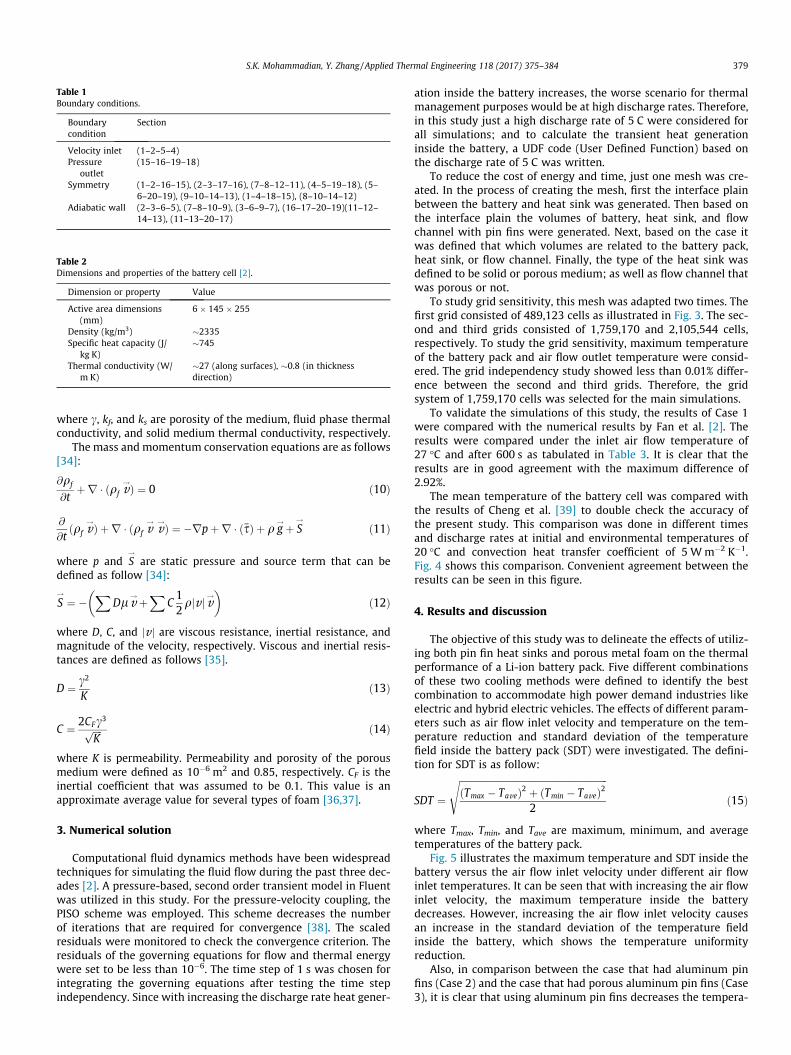
Table 1Boundary conditions.
Boundarycondition
Section
Velocity inlet (1–2–5–4)Pressure
outlet(15–16–19–18)
Symmetry (1–2–16–15), (2–3–17–16), (7–8–12–11), (4–5–19–18), (5–6–20–19), (9–10–14–13), (1–4–18–15), (8–10–14–12)
Adiabatic wall (2–3–6–5), (7–8–10–9), (3–6–9–7), (16–17–20–19)(11–12–14–13), (11–13–20–17)
Table 2Dimensions and properties of the battery cell [2].
Dimension or property Value
Active area dimensions(mm)
6 � 145 � 255
Density (kg/m3) �2335Specific heat capacity (J/
kg K)�745
Thermal conductivity (W/m K)
�27 (along surfaces), �0.8 (in thicknessdirection)
S.K. Mohammadian, Y. Zhang / Applied Thermal Engineering 118 (2017) 375–384 379
where c, kf, and ks are porosity of the medium, fluid phase thermalconductivity, and solid medium thermal conductivity, respectively.
The mass and momentum conservation equations are as follows[34]:
@qf
@tþr � ðqf v
!Þ ¼ 0 ð10Þ
@
@tðqf v
!Þ þr � ðqf v!v!Þ ¼ �rpþr � ð��sÞ þ q g
!þ S!
ð11Þ
where p and S!
are static pressure and source term that can bedefined as follow [34]:
S!¼ �
XDlv
!þX
C12qjv jv!
� �ð12Þ
where D, C, and jvj are viscous resistance, inertial resistance, andmagnitude of the velocity, respectively. Viscous and inertial resis-tances are defined as follows [35].
D ¼ c2
Kð13Þ
C ¼ 2CFc3ffiffiffiffiK
p ð14Þ
where K is permeability. Permeability and porosity of the porousmedium were defined as 10�6 m2 and 0.85, respectively. CF is theinertial coefficient that was assumed to be 0.1. This value is anapproximate average value for several types of foam [36,37].
3. Numerical solution
Computational fluid dynamics methods have been widespreadtechniques for simulating the fluid flow during the past three dec-ades [2]. A pressure-based, second order transient model in Fluentwas utilized in this study. For the pressure-velocity coupling, thePISO scheme was employed. This scheme decreases the numberof iterations that are required for convergence [38]. The scaledresiduals were monitored to check the convergence criterion. Theresiduals of the governing equations for flow and thermal energywere set to be less than 10�6. The time step of 1 s was chosen forintegrating the governing equations after testing the time stepindependency. Since with increasing the discharge rate heat gener-
ation inside the battery increases, the worse scenario for thermalmanagement purposes would be at high discharge rates. Therefore,in this study just a high discharge rate of 5 C were considered forall simulations; and to calculate the transient heat generationinside the battery, a UDF code (User Defined Function) based onthe discharge rate of 5 C was written.
To reduce the cost of energy and time, just one mesh was cre-ated. In the process of creating the mesh, first the interface plainbetween the battery and heat sink was generated. Then based onthe interface plain the volumes of battery, heat sink, and flowchannel with pin fins were generated. Next, based on the case itwas defined that which volumes are related to the battery pack,heat sink, or flow channel. Finally, the type of the heat sink wasdefined to be solid or porous medium; as well as flow channel thatwas porous or not.
To study grid sensitivity, this mesh was adapted two times. Thefirst grid consisted of 489,123 cells as illustrated in Fig. 3. The sec-ond and third grids consisted of 1,759,170 and 2,105,544 cells,respectively. To study the grid sensitivity, maximum temperatureof the battery pack and air flow outlet temperature were consid-ered. The grid independency study showed less than 0.01% differ-ence between the second and third grids. Therefore, the gridsystem of 1,759,170 cells was selected for the main simulations.
To validate the simulations of this study, the results of Case 1were compared with the numerical results by Fan et al. [2]. Theresults were compared under the inlet air flow temperature of27 �C and after 600 s as tabulated in Table 3. It is clear that theresults are in good agreement with the maximum difference of2.92%.
The mean temperature of the battery cell was compared withthe results of Cheng et al. [39] to double check the accuracy ofthe present study. This comparison was done in different timesand discharge rates at initial and environmental temperatures of20 �C and convection heat transfer coefficient of 5 Wm�2 K�1.Fig. 4 shows this comparison. Convenient agreement between theresults can be seen in this figure.
4. Results and discussion
The objective of this study was to delineate the effects of utiliz-ing both pin fin heat sinks and porous metal foam on the thermalperformance of a Li-ion battery pack. Five different combinationsof these two cooling methods were defined to identify the bestcombination to accommodate high power demand industries likeelectric and hybrid electric vehicles. The effects of different param-eters such as air flow inlet velocity and temperature on the tem-perature reduction and standard deviation of the temperaturefield inside the battery pack (SDT) were investigated. The defini-tion for SDT is as follow:
SDT ¼ffiffiffiffiffiffiffiffiffiffiffiffiffiffiffiffiffiffiffiffiffiffiffiffiffiffiffiffiffiffiffiffiffiffiffiffiffiffiffiffiffiffiffiffiffiffiffiffiffiffiffiffiffiffiffiffiffiffiffiffiffiffiffiffiðTmax � TaveÞ2 þ ðTmin � TaveÞ2
2
sð15Þ
where Tmax, Tmin, and Tave are maximum, minimum, and averagetemperatures of the battery pack.
Fig. 5 illustrates the maximum temperature and SDT inside thebattery versus the air flow inlet velocity under different air flowinlet temperatures. It can be seen that with increasing the air flowinlet velocity, the maximum temperature inside the batterydecreases. However, increasing the air flow inlet velocity causesan increase in the standard deviation of the temperature fieldinside the battery, which shows the temperature uniformityreduction.
Also, in comparison between the case that had aluminum pinfins (Case 2) and the case that had porous aluminum pin fins (Case3), it is clear that using aluminum pin fins decreases the tempera-
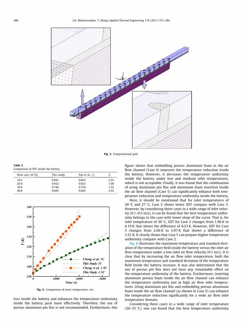
Fig. 3. Computational grid.
Table 3Comparison of SDT inside the battery.
Flow rate (m3/h) This study Fan et al. [2] %
10.2 0.841 0.863 2.5520.4 0.832 0.823 1.0830.6 0.746 0.756 1.3240.8 0.685 0.665 2.92
Fig. 4. Comparison of inner temperature rise.
380 S.K. Mohammadian, Y. Zhang / Applied Thermal Engineering 118 (2017) 375–384
ture inside the battery and enhances the temperature uniformityinside the battery pack more effectively. Therefore, the use ofporous aluminum pin fins is not recommended. Furthermore, this
figure shows that embedding porous aluminum foam in the airflow channel (Case 4) improves the temperature reduction insidethe battery. However, it decreases the temperature uniformityinside the battery under low and medium inlet temperatures,which is not acceptable. Finally, it was found that the combinationof using aluminum pin fins and aluminum foam insertion insidethe air flow channel (Case 5) can significantly enhance both tem-perature reduction and temperature uniformity inside the battery.
Here, it should be mentioned that for inlet temperatures of20 �C and 27 �C, Case 2 shows lower SDT compare with Case 5.However, by considering these cases in a wide range of inlet veloc-ity (0.1–0.5 m/s), it can be found that the best temperature unifor-mity belongs to the case with lower slope of the curve. That is, forinlet temperature of 20 �C, SDT for Case 2 changes from 1.96 K to6.19 K that shows the difference of 4.23 K. However, SDT for Case5 changes from 2.66 K to 5.97 K that shows a difference of3.31 K. It clearly shows that Case 5 can prepare higher temperatureuniformity compare with Case 2.
Fig. 6 illustrates the maximum temperature and standard devi-ation of the temperature field inside the battery versus the inlet airflow temperature under a low inlet air flow velocity (0.1 m/s). It isclear that by increasing the air flow inlet temperature, both themaximum temperature and standard deviation of the temperaturefield inside the battery increase. It was also determined that theuse of porous pin fins does not have any remarkable effect onthe temperature uniformity of the battery. Furthermore, insertingaluminum porous foam inside the air flow channel can enhancethe temperature uniformity just at high air flow inlet tempera-tures. Using aluminum pin fins and embedding porous aluminumfoam inside the air flow channel (as shown in Case 5) can enhancethe temperature reduction significantly for a wide air flow inlettemperature domain.
Considering these cases in a wide range of inlet temperature(20–35 �C), one can found that the best temperature uniformity
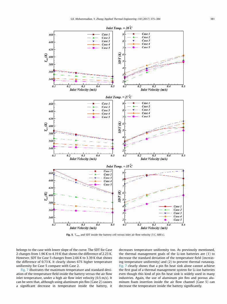
Fig. 5. Tmax and SDT inside the battery cell versus inlet air flow velocity (5 C, 600 s).
S.K. Mohammadian, Y. Zhang / Applied Thermal Engineering 118 (2017) 375–384 381
belongs to the case with lower slope of the curve. The SDT for Case2 changes from 1.96 K to 4.19 K that shows the difference of 2.23 K.However, SDT for Case 5 changes from 2.66 K to 3.39 K that showsthe difference of 0.73 K. It clearly shows 67% higher temperatureuniformity for Case 5 compare with Case 2.
Fig. 7 illustrates the maximum temperature and standard devi-ation of the temperature field inside the battery versus the air flowinlet temperature, under a high air flow inlet velocity (0.5 m/s). Itcan be seen that, although using aluminum pin fins (Case 2) causesa significant decrease in temperature inside the battery, it
decreases temperature uniformity too. As previously mentioned,the thermal management goals of the Li-ion batteries are (1) todecrease the standard deviation of the temperature field (increas-ing temperature uniformity) and (2) to prevent thermal runaway.Fig. 7 clearly shows that a pin fin heat sink alone cannot achievethe first goal of a thermal management system for Li-ion batterieseven though this kind of pin fin heat sink is widely used in manyindustries. Again, the use of aluminum pin fins and porous alu-minum foam insertion inside the air flow channel (Case 5) candecrease the temperature inside the battery significantly.

Fig. 6. Tmax and SDT inside the battery cell versus inlet air flow temperature for air flow velocity of 0.1 m/s (5 C, 600 s).
Fig. 7. Tmax and SDT inside the battery cell versus inlet air flow temperature for air flow velocity of 0.5 m/s (5 C, 600 s).
382 S.K. Mohammadian, Y. Zhang / Applied Thermal Engineering 118 (2017) 375–384
After comparing the thermal behavior of the battery cell in thedifferent cases and observing the effects of the metal foaminsertion, the next step was to take the energy cost into consider-ation. Therefore, all five different cases were compared to eachother based on their pumping power, which is defined as:
P ¼ _Vðpin � poutÞ ð16Þwhere pin and pout are the pressures at the inlet and outlet of thechannel, respectively. _V is the volumetric flow rate (m3/s), whichis defined as:
_V ¼ uinAin ð17Þwhere Ain and uin are cross section areas of the channel and velocityat the inlet, respectively.
Fig. 8 shows the maximum temperature and standard deviationof the temperature field inside the battery versus the pumpingpower under different air flow inlet temperatures. Here, it shouldbe mentioned that the amount of pumping power in Fig. 8 is justfor the test section that was described in Fig. 1. The pumping powerrelated to the whole battery pack would be much higher. FromFig. 8, it is clear that based on the amount of energy that needs tobe consumed for cooling the battery pack, the use of aluminumpin fins (Case 2) and porous aluminum foam pin fins (Case 3) wereunable to improve the temperature reduction inside the batterypack for a wide range of air flow inlet temperatures. However, they
can enhance the temperature uniformity inside the battery. Usingporous aluminum foam without utilizing any pin fin (Case 4) candecrease the maximum temperature inside the battery. However,Case 4’s porous aluminum foam without pin fin is unable toimprove the temperature uniformity. Finally, utilizing aluminumpin fins and inserting porous aluminum foam inside the air flowchannel (Case 5) enhances the temperature reduction, andimproves the temperature uniformity inside the battery pack.
5. Conclusions
Three-dimensional transient thermal analysis was carried out toinvestigate an air-cooledmodule of Li-ion battery cells with five dif-ferent kind of heat sinks. The effects of porous aluminum insertion,types of pin fins (solid or porous), air flow inlet temperature, and airflow inlet velocity on themaximumtemperature and standard devi-ation of the temperature field inside the battery cell were investi-gated. The results of this research led to the following conclusions:
� At all air flow inlet velocities and low pumping powers, the useof pin fins decreases the maximum temperature inside the bat-tery cell. However, at high pumping powers, pin fins causehigher temperature. Furthermore, at all pumping powers andlow air flow velocities, all solid (non-porous) aluminum pin finscan improve the temperature uniformity inside a Li-ion battery.

Fig. 8. Tmax and SDT inside the battery cell versus pumping power (5 C, 600 s).
S.K. Mohammadian, Y. Zhang / Applied Thermal Engineering 118 (2017) 375–384 383
� Porous aluminum pin fins are unable to enhance the tempera-ture reduction or improve the temperature uniformity insidethe Li-ion battery.
� Embedding porous aluminum foam inside the air flow channelenhances temperature reduction inside the battery. However,it is unable to improve temperature uniformity.
� The combination of inserting porous aluminum foam and alu-minum pin fins inside the air flow channel reduces the tempera-ture inside the battery and improves temperature uniformity.This combination is recommended for use in high power demandindustries.
References
[1] M.R. Giuliano, S.G. Advani, A.K. Prasad, Thermal analysis and management oflithium–titanate batteries, J. Power Sources 196 (15) (2011) 6517–6524.
[2] L. Fan, J.M. Khodadadi, A.A. Pesaran, A parametric study on thermalmanagement of an air-cooled lithium-ion battery module for plug-in hybridelectric vehicles, J. Power Sources 238 (2013) 301–312.
[3] Y.S. Choi, D.M. Kang, Prediction of thermal behaviors of an air-cooled lithium-ion battery system for hybrid electric vehicles, J. Power Sources 270 (2014)273–280.
[4] G. Karimi, X. Li, Thermal management of lithium-ion batteries for electricvehicles, Int. J. Energy Res. 37 (1) (2013) 13–24.

384 S.K. Mohammadian, Y. Zhang / Applied Thermal Engineering 118 (2017) 375–384
[5] G. Karimi, A.R. Dehghan, Thermal analysis of high-power lithium-ion batterypacks using flow network approach, Int. J. Energy Res. 38 (14) (2014) 1793–1811.
[6] H. Fathabadi, A novel design including cooling media for lithium-ion batteriespack used in hybrid and electric vehicles, J. Power Sources 245 (2014) 495–500.
[7] F. He, H. Wang, L. Ma, Experimental demonstration of active thermal control ofa battery module consisting of multiple Li-ion cells, Int. J. Heat Mass Transf. 91(2015) 630–639.
[8] S.K. Mohammadian, Y. Zhang, Thermal management optimization of an air-cooled Li-ion battery module using pin-fin heat sinks for hybrid electricvehicles, J. Power Sources 273 (2015) 431–439.
[9] D. Chen, J. Jiang, G. Kim, C. Yang, A. Pesaran, Comparison of different coolingmethods for lithium ion battery cells, Appl. Therm. Eng. 94 (2016) 846–854.
[10] W. Tong, K. Somasundaram, E. Birgersson, A.S. Mujumdar, C. Yap, Thermo-electrochemical model for forced convection air cooling of a lithium-ionbattery module, Appl. Therm. Eng. 99 (2016) 672–682.
[11] M.R. Giuliano, A.K. Prasad, S.G. Advani, Experimental study of an air-cooledthermal management system for high capacity lithium–titanate batteries, J.Power Sources 216 (2012) 345–352.
[12] S.K. Mohammadian, S.M. Rassoulinejad-Mousavi, Y. Zhang, Thermalmanagement improvement of an air-cooled high-power lithium-ion batteryby embedding metal foam, J. Power Sources 296 (2015) 305–313.
[13] Z. Wang, Z. Zhang, L. Jia, L. Yang, Paraffin and paraffin/aluminum foamcomposite phase change material heat storage experimental study based onthermal management of Li-ion battery, Appl. Therm. Eng. 78 (2015) 428–436.
[14] S.K. Mohammadian, Y. Zhang, Temperature uniformity improvement of an air-cooled high-power lithium-ion battery using metal and nonmetal foams, J.Heat Transf. 138 (11) (2016), 114502–114502-4.
[15] X.-H. Yang, S.-C. Tan, J. Liu, Thermal management of Li-ion battery with liquidmetal, Energy Convers. Manage. 117 (2016) 577–585.
[16] C. Lan, J. Xu, Y. Qiao, Y. Ma, Thermal management for high power lithium-ionbattery by minichannel aluminum tubes, Appl. Therm. Eng. 101 (2016) 284–292.
[17] J. Xu, C. Lan, Y. Qiao, Y. Ma, Prevent thermal runaway of lithium-ion batterieswith minichannel cooling, Appl. Therm. Eng. 110 (2017) 883–890.
[18] H. Park, A design of air flow configuration for cooling lithium ion battery inhybrid electric vehicles, J. Power Sources 239 (2013) 30–36.
[19] X.M. Xu, R. He, Research on the heat dissipation performance of battery packbased on forced air cooling, J. Power Sources 240 (2013) 33–41.
[20] H. Sun, R. Dixon, Development of cooling strategy for an air cooled lithium-ionbattery pack, J. Power Sources 272 (2014) 404–414.
[21] T. Wang, K.J. Tseng, J. Zhao, Z. Wei, Thermal investigation of lithium-ionbattery module with different cell arrangement structures and forced air-cooling strategies, Appl. Energy 134 (2014) 229–238.
[22] L. Martín-Martín, J. Gastelurrutia, N. Nieto, J.C. Ramos, A. Rivas, I. Gil, Modelingbased on design of thermal management systems for vertical elevationapplications powered by lithium-ion batteries, Appl. Therm. Eng. 102 (2016)1081–1094.
[23] J. Xun, R. Liu, K. Jiao, Numerical and analytical modeling of lithium ion batterythermal behaviors with different cooling designs, J. Power Sources 233 (2013)47–61.
[24] Z. Liu, Y. Wang, J. Zhang, Z. Liu, Shortcut computation for the thermalmanagement of a large air-cooled battery pack, Appl. Therm. Eng. 66 (1–2)(2014) 445–452.
[25] K. Yu, X. Yang, Y. Cheng, C. Li, Thermal analysis and two-directional air flowthermal management for lithium-ion battery pack, J. Power Sources 270(2014) 193–200.
[26] S.K. Mohammadian, Y.-L. He, Y. Zhang, Internal cooling of a lithium-ion batteryusing electrolyte as coolant through microchannels embedded inside theelectrodes, J. Power Sources 293 (2015) 458–466.
[27] S.K. Mohammadian, Y. Zhang, Effects of size of microchannels on thermo-electrical performance of an internally cooled Li-ion battery cell, J.Electrochem. En. Conv. Stor. 13 (4) (2017), 044501–044501-5.
[28] D. Bernardi, E. Pawlikowski, J. Newman, A general energy balance for batterysystems, J. Electrochem. Soc. 132 (1) (1985) 5–12.
[29] W.B. Gu, C.Y. Wang, Thermal-electrochemical modeling of battery systems, J.Electrochem. Soc. 147 (8) (2000) 2910–2922.
[30] T.M. Bandhauer, Electrochemical-thermal Modeling and Microscale PhaseChange for Passive Internal Thermal Management of Lithium Ion Batteries(PHD Dissertation), School Mechanical Engineering, Georgia Institute ofTechnology, 2011.
[31] H. Fathabadi, High thermal performance lithium-ion battery pack includinghybrid active–passive thermal management system for using inhybrid/electric vehicles, Energy 70 (2014) 529–538.
[32] J. Zhao, Z. Rao, Y. Li, Thermal performance of mini-channel liquid cooledcylinder based battery thermal management for cylindrical lithium-ion powerbattery, Energy Convers. Manage. 103 (2015) 157–165.
[33] Y. Huo, Z. Rao, X. Liu, J. Zhao, Investigation of power battery thermalmanagement by using mini-channel cold plate, Energy Convers. Manage. 89(2015) 387–395.
[34] ANSYS Inc, Ansys Fluent 12.0 User’s Guide, 2009.[35] W.M. Clearman, Measurement and Correlation of Directional Permeability and
Forchheimer’s Inertial Coefficient of Microporous Structures Used in PulseTube Cryocoolers (MSc thesis), Georgia Institute of Technology, 2007.
[36] R.C. Givler, S.A. Altobelli, A determination of the effective viscosity for theBrinkman-Forchheimer flow model, J. Fluid Mech. 258 (1994) 355–370.
[37] D.W. Kim, Convection and Flow Boiling in Microgaps and Porous Foam Coolers(Ph.D. dissertation), Department of Mechanical Engineering, University ofMaryland, College Park, 2007.
[38] D.A. Jones, D.B. Clarke, Simulation of Flow Past a Sphere using the Fluent Code,Australian Government, Department of Defence (Defence Science andTechnology Organization), 2008, p. DSTO-TR-2332.
[39] L. Cheng, Ke Chen, Fengchun Sun, Peng Tang, Hongwei Zhao, Research onThermophysical Properties Identification and Thermal Analysis of EV Li-ionBattery, IEEE, 2009, pp. 1643–1648.