Applicaton Note - · PDF fileUMTS P-CPICH Demodulation option,
11
Applicaton Note UMTS measurements with the Selective Radiation Meter SRM-3000 Determining field exposure levels in the vicinity of UMTS transmitting equipment UMTS, the Universal Mobile Telecommunications System, is a third- generation mobile phone standard (3G). UMTS is widely used in Europe. Compared with GSM (2G), UMTS allows variable and much higher data transmission rates. Since a higher data rate is coupled with a shorter range, a higher density of transmitting stations is required. Other wireless services as well as UMTS and GSM often share the same antenna location, so the proportion of the total field exposure level due to UMTS can only be determined by selective measurement. This Application Note describes an example field emission measurement on UMTS transmitting equipment using the SRM-3000 and its evaluation from the point of view of human safety. Contents 1 Background Page 2 2 Standards and regulations Page 3 3 Preparation for measurement Page 3 4 Fundamental measurement settings Page 4 5 UMTS frequency channel measurement using Safety Evaluation mode Page 5 6 UMTS frequency channel measurement using Spectrum Analysis mode Page 6 7 Measuring a UMTS channel using Spectrum Analysis mode Page 6 8 Measuring UMTS cells using UMTS P-CPICH Demodulation mode Page 7 9 Determining maximum field exposure level by extrapolation Page 7 Typical multiple antenna array for GSM 900, GSM 1800 and UMTS 10 Evaluating the results and generating a report Page 8 Annex: Calculating the center frequency; Abbreviations Page 10 References Page 11 © 2008 Narda Safety Test Solutions GmbH Sandwiesenstr. 7 72793 Pfullingen, Deutschland Tel.: +49 7121 9732-777 Fax: +49 7121 9732-790 E-mail: [email protected] www.narda-sts.de AN_HF_1007_UMTS_Measurements Page 1 of 11
Transcript of Applicaton Note - · PDF fileUMTS P-CPICH Demodulation option,

Applicaton Note
UMTS measurements with the Selective Radiation Meter SRM-3000 Determining field exposure levels in the vicinity of UMTS transmitting equipment UMTS, the Universal Mobile Telecommunications System, is a third-generation mobile phone standard (3G). UMTS is widely used in Europe. Compared with GSM (2G), UMTS allows variable and much higher data transmission rates. Since a higher data rate is coupled with a shorter range, a higher density of transmitting stations is required. Other wireless services as well as UMTS and GSM often share the same antenna location, so the proportion of the total field exposure level due to UMTS can only be determined by selective measurement. This Application Note describes an example field emission measurement on UMTS transmitting equipment using the SRM-3000 and its evaluation from the point of view of human safety.
Contents
1 Background Page 2 2 Standards and regulations Page 3 3 Preparation for measurement Page 3 4 Fundamental measurement settings Page 4 5 UMTS frequency channel measurement using
Safety Evaluation mode Page 5 6 UMTS frequency channel measurement using
Spectrum Analysis mode Page 6 7 Measuring a UMTS channel using Spectrum Analysis mode Page 6 8 Measuring UMTS cells using
UMTS P-CPICH Demodulation mode Page 7 9 Determining maximum field exposure level by extrapolation Page 7 Typical multiple antenna array for GSM 900, GSM 1800
and UMTS 10 Evaluating the results and generating a report Page 8
Annex: Calculating the center frequency; Abbreviations Page 10 References Page 11 © 2008 Narda Safety Test Solutions GmbH Sandwiesenstr. 7 72793 Pfullingen, Deutschland Tel.: +49 7121 9732-777 Fax: +49 7121 9732-790 E-mail: [email protected] www.narda-sts.de
AN_HF_1007_UMTS_Measurements Page 1 of 11

1 Background UMTS utilizes a wide-band code-division multiple access procedure (W-CDMA) for transmitting voice and data signals. The transmitted voice and data channels differ in the way they are coded, but not necessarily in their frequencies. UMTS frequency channels Each provider has obtained a license to use one or more frequency channels, each having a bandwidth of 5 MHz. Each UMTS base station (Node-B) operates on one of these frequency channels. Thus, many cells utilize one and the same frequency. There are two variants: UMTS-FDD occupies separate pairs of frequency channels for the uplink and downlink, while UMTS-TDD uses a common frequency channel for both directions (see table). As TDD is seldom used, this Application Note only looks at FDD. Normally, only the downlink (from the base station to the mobile device) is of interest when considering human safety because its field strength predominates in close proximity to the transmitter location. Code channels The information in the separate voice and data channels is encoded individually by a Channelization Code and simultaneously spread over the entire width of a frequency channel. The complete information stream in the downlink for a cell is again scrambled using a Scrambling Code. There are 512 sets of scrambling codes which are used to distinguish the individual cells from one another. P-CPICH One P-CPICH (Primary Common Pilot Channel) per cell is embedded in the multiplex signal. This channel is transmitted continuously at a constant power level. The field strength of this channel can be measured by decoding it, and assigned to the particular cell by means of the scrambling code. The value can be used to extrapolate the “worst case” scenario, i.e. the maximum field strength when the cell capacity is fully utilized.
Universal Mobile Telecommunications System Frequency range for FDD uplink
1920 – 1980 MHz (12 frequency channels of 5 MHz)
Frequency range for FDD downlink
2110 – 2170 MHz (12 frequency channels of 5 MHz)
Frequency ranges for TDD 1900 – 1920 MHz (4 frequency channels of 5 MHz) 2010 – 2025 MHz (3 frequency channels of 5 MHz)
Carrier frequency (center frequency)
Can be freely chosen by the provider within a frequency channel, but must be an integer multiple of 100 kHz
Number of channels per carrier
Variable, depends on the data transmission rates of the individual channels
Modulation QPSK; 6-QAM also used for HSDPA
Access type CDMA
Left: Overview of commonly used UMTS frequencies and other UMTS properties. Uplink: from the mobile device (phone) to the base station (Node B). Downlink: from the base station to the mobile device – this is usually the subject of measurements. Many service providers give a channel number to the exact center frequency of a UMTS frequency channel they are using. The calculation of the associated frequency is described in the Annex.
Schematic diagram of the frequency spectrum of UMTS channels.
Provider 2 Provider 1 Traffic Traffic P-CPICH
P-CPICH Traffic
Traffic
P-CPICH P-CPICH 5 MHz 5 MHz 5 MHz 5 MHz
Typical arrangement of UMTS antennas, viewed from above. The antennas are so-called sector antennas, each covering an angle of 120°. Two antennas on adjacent masts radiate in each direction (space diversity). Thus, a total of three cells is installed and fed from just three Node B base stations, which are differentiated by three scrambling codes. Several such arrays may be installed at one and the same location. The external appearance of UMTS antennas is very similar to that of GSM antennas.
AN_HF_1007_UMTS_Measurements Page 2 of 11

2 Standards and regulations Limit value curves for electric field strength as per ICNIRP.
transient peak values
Frequency
Electricfield strength (A/m)
In 1998 the International Commission for Non-Ionizing Radiation Protection (ICNIRP) published its “Guidelines on Limiting Exposure to Non-Ionizing Radiation” [1, 2]. These guidelines include frequency-dependent limit values in the form of two different limit value curves: a higher one for protection in the work environment (occupational) and a lower one for the general public. The higher values apply in controlled areas where safety measures have been taken and which are only accessible to specially trained personnel. This applies, for example, to mobile phone antenna sites, for which operators have to define safe distances. The limit values, as well as their division into two parts, are reflected in the European guidelines. Occupational safety is governed by Guideline 2004/40/EC of 29 April 2004 [3], whereas Recommendation 1999/519/EC [4] for protecting the general public was published much earlier, on 12 July 1999. In addition, many countries have their own national standards, most of which are based on the ICNIRP limit values, although some specify lower levels for the limit values.
The measuring equipment depends on the measurement task. A complete set of equipment comprises: • SRM Mainframe with the latest firmware
(download from www.narda-sts.de) as well as the UMTS P-CPICH Demodulation option,
• Three-axis (isotropic) E-field antenna for SRM-3000 up to 3 GHz – or – single-axis E-field antenna for the frequency range up to 3 GHz,
• RF cable, 1.5 m, • AC Adapter / Charger or spare rechargeable
battery if no power supply available on site, • Writing materials for noting down measurement
setups, local conditions, frequencies, measurement settings and possible sources of interference – or – Notebook PC with the latest SRM-TS PC software for controlling the SRM, saving measurement results and recording comments (download from www.narda-sts.de)
If you are using the dot matrix measurement method with a single-axis antenna, you will also need: • Tripod • Antenna holder for single- and three-axis
measuring antennas • RF cable, 5 m.
3 Preparation for measurement UMTS measurements can generally be made “on the move”. The measuring antenna can be mounted directly on the SRM basic unit or connected to it by the 1.5 m long RF cable for this purpose. The three-axis (isotropic) E-field antenna is recommended for making measurements using the dot matrix method, where specific points in the space are measured according to a fixed pattern. The SRM basic unit then determines the isotropic (non-directional) result for each measured point automatically. You can also use a single-axis antenna for the dot matrix method, but the procedure is more time-consuming. Refer to the SRM-3000 Operating Manual under “Isotropic measurements with a single-axis antenna” for more information. Either the three-axis or the single-axis E-field antenna can be used for the pendulum method, where the spatial volume is swept continuously. If the antenna is connected to the SRM basic unit using the 1.5 m long RF cable, the instrument can be attached to a belt and the antenna panned through the space by hand. The single-axis antenna should be rotated during panning to take account of the polarization of the field. This is not necessary if the three-axis antenna is used. Important: When using the pendulum method, the panning rate must be slow enough for the SRM to make two or three measurements for each position of the antenna.
AN_HF_1007_UMTS_Measurements Page 3 of 11

4 Fundamental measurement settings Setting the measurement range (MR) In most cases, the automatic “MR Search” function will be the quickest way to set the measurement range in all operating modes. The measurement range must be set manually only when field strengths from impulse type sources such as radar located nearby predominate (see Application Note AN_HF_1003 “Radar Measurements”). The setting can of course be made individually following the results of an overview measurement.
Figure 1: The overview measurement shows fields from GSM-900, GSM-1800, and UMTS at 2100 MHz.Measurement settings: Minimum Frequency 75 MHz Maximum Frequency 3 GHz Resolution Bandwidth 5 MHz MR depends on field situation Unit V/m Result Type MAX
Overview measurement in Spectrum Analysis mode An overview measurement of the entire available frequency range setting (Full Span) is always recommended if there are other dominant field sources in the vicinity of the UMTS transmitting equipment such as radio transmitters, which can affect control of the measuring instrument (figure 1). Starting from a large measurement range MR (low sensitivity), the MR is progressively reduced (sensitivity increased) until the spectrum becomes clearly separated from the noise signal. Using the “Highest Peak” marker function, the field strength of the highest spectral line peak is read off and the measurement range set to approximately twice this value. Setting the frequency range (Span) It is sensible to restrict the frequency range to the frequencies of interest to achieve good screen resolution and fast measurement speeds. The upper and lower frequency limits can be selected using “Fmin / Fmax” or the zoom functions can be used for this (figures 2, 3; also refer to the Operating Manual).
Figure 2: The frequency range can also be set using Zoom min / Zoom max.
Setting the resolution bandwidth (RBW) Since UMTS uses a frequency channel spacing of 5 MHz, a resolution bandwidth of 5 MHz is also sufficient to resolve the spectrum into individual channels. The SRM uses a special algorithm to ensure that the real value is displayed when making evaluations with the Peak Table or using the Highest Peak marker function even if the selection filter is not exactly tuned to the channel center frequency. This does not apply if the marker is positioned using the rotary control. Setting the result type (Result Type) The Result Type depends on the purpose of the measurement and the standard or regulation used to assess the results.
Figure 3: UMTS downlink spectrum. Measurement settings differing from those above: Resolution Bandwidth 1 MHz Unit mV/m Result Type AVG
Setting the display units (Display Unit) The choice that needs to be made here is whether to measure in physical units (V/m, A/m, W/m2, dBµV/m etc.) or as a percentage of the limit value (%, see section 10). Subsequent conversion from one set of physical units to another is possible.
AN_HF_1007_UMTS_Measurements Page 4 of 11
5 UMTS frequency channel measurement using Safety Evaluation mode The SRM 3000 “Safety Evaluation” mode is useful if a quick assessment of the overall field situation is required, since it is the easiest way to display the results. It does however require that corresponding Service Tables defining the frequency ranges of the UMTS frequency channels of interest (e.g. according to service providers) are stored in the instrument. Recommended settings:
Figure 4: Safety Evaluation using a service table specially created for German UMTS service providers and ACT evaluation mode. Results are displayed in units of field strength.
• Resolution bandwidth RBW: 50 kHz • Measurement Range MR: as described in section 4 • Result Type: As defined by the standard or regulation to be used for
evaluating the results. Example: Client-specific Service Table “UMTS_D” and ACT evaluation mode (figure 4). The SRM displays the instantaneous downlink field strength values here, broken down according to providers, together with the Total value. “Others” represents the field strengths that lie between the defined frequency channels. Results below a pre-settable threshold value are shown by the SRM as “less than” (e.g. <7.261 mV/m). These values can in any case be ignored when calculating the overall field exposure level. The environmental impact at the measurement location can be read off directly.
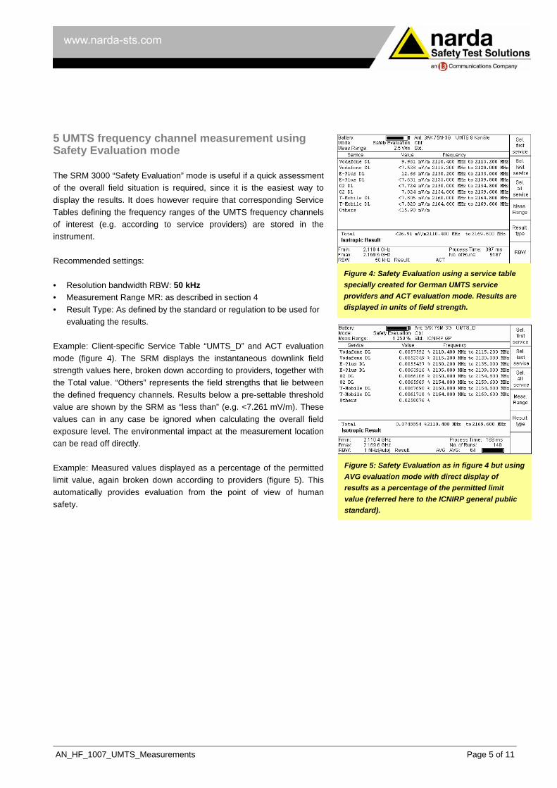
Figure 5: Safety Evaluation as in figure 4 but using AVG evaluation mode with direct display of results as a percentage of the permitted limit value (referred here to the ICNIRP general public standard).
Example: Measured values displayed as a percentage of the permitted limit value, again broken down according to providers (figure 5). This automatically provides evaluation from the point of view of human safety.
AN_HF_1007_UMTS_Measurements Page 5 of 11

6 UMTS frequency channel measurement using Spectrum Analysis mode “Spectrum Analysis” mode allows measurement of field strengths over the entire UMTS frequency channel, just like “Safety Evaluation” mode. The evaluation is a bit more complex, but the measurement gives additional information about the type of spectrum.
Figure 6: Field strength spectrum in the UMTS frequency band (FDD downlink). Measurement settings: Minimum Frequency 2.1 GHz Maximum Frequency 2.171 GHz Resolution Bandwidth 1 MHz The values at the marker position are displayed top right. As a service table has been recorded, the name of the service provider is also shown in each case.
Recommended settings: • Frequency range (Span):
Fmin, Fmax corresponding to the downlink frequency range • Resolution bandwidth (RBW):
1 MHz or less • Result Type:
ACT to view the instantaneous value MAX to view the maximum value during the measurement period AVG to determine the average over e.g. a period of 6 minutes
Spatial averaging: Refer to the Application Note “GSM Measurements with the Selective Radiation Meter SRM-3000” (AN_HF_1005). The Integration over Frequency Band function can be used to determine the field strength of the entire UMTS frequency channel (see section 10). 7 Measuring a UMTS channel using Spectrum Analysis mode Figure 7: Using the Zoom function to manually
restrict the frequency range to a single UMTS frequency band.
The spectrum analysis measurement described above can be used to determine the field strength of a UMTS frequency channel by setting the integration limits accordingly. More exact information about the channel spectrum can be obtained by restricting the frequency range to the apparent channel width using the Zoom function (figure 7) or by entering the exact frequencies numerically (figure 8): • Frequency range (Span):
Fcent corresponding to the center frequency used by the UMTS service provider. If the provider specifies a channel number, the frequency can be calculated using a simple formula (see Annex). Fspan = 10 MHz
• Resolution bandwidth (RBW): 20 kHz, maximum 1/10 Fspan Figure 8: Field strength of a UMTS frequency
band. Measurement settings: Center Frequency 2.1128 GHz Frequency Span 7.42 MHz Resolution Bandwidth 20 kHz
• Result Type: ACT to view the instantaneous value MAX to view the maximum value during the measurement period AVG to determine the average over e.g. a period of 6 minutes
AN_HF_1007_UMTS_Measurements Page 6 of 11

8 Measuring a UMTS cell using UMTS P-CPICH Demodulation mode In “UMTS P-CPICH Demodulation” mode (option), the SRM decodes all the scrambling codes that are present in a selected UMTS frequency channel. In his way, the instrument can separately determine and list the contribution of each individual cell to the overall field strength of a UMTS frequency channel. It also calculates the total of all these contributions. In addition to this, the SRM displays the analog measurement value. This corresponds to the actual field exposure level integrated over the complete UMTS frequency channel of 5 MHz.
Figure 9: Field strengths of individual UMTS cells within a UMTS frequency band. Measurement settings: Center frequency Fcent 2.1128 GHz Result Type ACT
Results: Scr. Identity of the UMTS cell given by the
decoded scrambling code number Value Measured instantaneous P-CPICH
field strength in mV/m Max. Value Maximum P-CPICH field strength that
has occurred since the start of the measurement
Value/Analog Ratio of the instantaneous P-CPICH value of one UMTS cell to the analog field strength measurement value for the entire UMTS frequency band in dB
Total Total field strength of all decoded P-CPICHs (power sum)
Analog Analog field strength measurement value for the entire UMTS frequency band.
Recommended settings: • Frequency:
Fcent corresponding to the center frequency used by the UMTS service provider, to the exact 100 kHz. It is easier to enter the UMTS channel number (setting made using the CONF menu).
• Demodulation algorithm: FAST if a high measurement speed is needed, e.g. when using the pendulum method SENSITIVE if weak signals from distant cells are also to be detected and decoded
• Result Type: ACT to view the instantaneous value AVG to determine the average over e.g. a period of 6 minutes
Save the result(s) and evaluate as described in section 10. 9 Determining maximum field exposure level by extrapolation By means of a settable extrapolation factor, the SRM can calculate the worst case situation which would occur if all cells were operating at full capacity. The ratio of the total possible transmitted power level to the power level of the P-CPICH is known and can therefore be requested from the service provider. Figure 10: Field strengths of individual UMTS cells
within a UMTS frequency band with extrapolation to give the possible maximum value. Setting: Extrapolation factor 3.3 All the results except the analog value are now multiplied by the extrapolation factor, even though they are displayed here in dBµV/m.
The extrapolation factor applies to all cells equally, i.e. the SRM multiplies all the individual results (Value, Max. Value) and the total result (Total) by this extrapolation factor, but not the result of the analog measurement.
AN_HF_1007_UMTS_Measurements Page 7 of 11

Figure 12: Spectrum evaluation using the SRM-TS PC software and the Integration over Frequency Band function.
Figure 13: You can switch between different physical units in all operating modes in the SRM itself as well as in the PC software.
Figure 11: Results of a Safety Evaluation displayed using the SRM-TS PC software.
10 Evaluating the results and generating a report The client requesting measurements of field emissions is ultimately interested in knowing whether field strengths are within the permitted limit values, or which service provider is exceeding the limits (and by how much) and who therefore needs to reduce output power. Hence, an assessment of the results relative to the limit values is part of the evaluation. It is useful to have the results in terms of physical units when making environmental measurements so that they can be compared with the limit values prescribed for the measurement location, for example. Results expressed as a percentage of the permitted limit value are most convenient when making measurements in connection with human safety. Safety Evaluation This operating mode supplies the results for the UMTS frequency band and individual frequency channels or providers corresponding to the recorded Service Table (figure 11). Physical values only need to be compared with the permitted values. The results as a percentage of the permitted limit value are shown directly – a special feature of the SRM-3000. Spectrum Analysis: Evaluation using Integration over Frequency Band The result in this operating mode must be determined using the “Integration over Frequency Band” function. The SRM can perform this function directly (figure 8). It is more convenient to use the SRM-TS PC software (figure 12). For example, results can be integrated over precisely the frequency band occupied by a service provider. The field exposure caused by the antennas of this provider can then be read off directly in figures. Integration over measured values obtained using the MAX result type tends to result in over-estimation of the field exposure level because the maximum values do not necessarily all occur at the same time.
AN_HF_1007_UMTS_Measurements Page 8 of 11

Spectrum Analysis: Evaluation using the Peak Table
Figure 14: Extra-polation performed after measure-ment using the SRM-TS PC software.
The Peak Table gives a rapid overview during evaluation. It can be opened in the SRM-TS PC software and in the data memory of the SRM itself for each spectrum. UMTS P-CPICH Demodulation As described in section 9, the SRM uses the variable extrapolation factor to automatically extrapolate the instantaneous field strength to give the maximum possible field strengths. The extrapolation factor can also be set or adjusted subsequently (figure 14). Accounting for measurement uncertainty Measurement uncertainty must be taken into account in all results. Please refer to our Application Note “Accounting for Measurement Uncertainty in the SRM-3000” (AN_HF_1004). A measurement report is usually prepared to record the evaluation and assessment. The SRM-TS PC software is very useful for this. The measurement data can be copied directly into the measurement report using simple copy and paste functions, or the measurement data sets can be exported to standard spreadsheet applications.
AN_HF_1007_UMTS_Measurements Page 9 of 11

Annex: Calculating the center frequency from the channel number
Service providers often specify a number denoting the exact center frequency of a UMTS frequency channel that they are using. This number is known as the UARFCN. The corresponding frequency is determined using the following equation:
MHzUARFCNf5
=
Example: UARFCN = 10836 Center frequency = 2167.2 MHz The SRM allows you to enter the channel number and calculates the corresponding center frequency automatically. Abbreviations 16-QAM 16-stage quadrature amplitude modulation E-field Electric field FDD Frequency Division Duplex HSDPA High Speed Downlink Packet Access ITU International Telecommunication Union MR Measurement range P-CPICH Primary Common Pilot Channel QPSK Quadrature Phase Shift Keying RBW Resolution bandwidth RMS Root mean square SRM Selective Radiation Meter TCH Traffic channel TDD Time Division Duplex UARFCN UMTS Absolute Radio Frequency Channel Number W-CDMA Wideband Code Division Multiple Access
AN_HF_1007_UMTS_Measurements Page 10 of 11

References [1] Guidelines on Limiting Exposure to Non-Ionizing Radiation. International Commission on Non-Ionizing Radiation
Protection (ICNIRP), July 1999; ISBN 3-9804789-6-3. [2] Directive 2004/40/EC of the European Parliament and the Council of Europe on the minimum health and safety
requirements regarding the exposure of workers to the risks arising from physical agents (electromagnetic fields) (18th separate directive according to Article 16 Paragraph 1 of Directive 89/391/EEC) of 29 April 2004.
[3] Council Recommendation of 12 July on the limitation of exposure of the general public to electromagnetic fields
(0 Hz to 300 GHz) (1999/519/EC). Official Journal of the European Communities L 199/59, 30.7.1999. [4] BGV B11: Unfallverhütungsvorschrift Elektromagnetische Felder (Berufsgenossenschaftliche Vorschrift für
Sicherheit und Gesundheit bei der Arbeit). 1st June 2001. [5] Sechsundzwanzigste Verordnung zur Durchführung des Bundes-Immissionsschutzgesetzes (Verordnung über
elektromagnetische Felder – 26. BImSchV). 16th December 1996. [6] prEN 50413:2005: Basic standard for measurement and calculation methods for the exposure of persons to
electric, magnetic and electromagnetic fields (0 Hz to 300 GHz). [7] DIN VDE 0848-1 (VDE 0848 Teil 1):2000-08: Sicherheit in elektrischen, magnetischen und elektromagnetischen
Feldern. Teil 1: Definitionen, Mess- und Berechnungsverfahren. [8] Revised ECC Recommendation (02)04: Measuring non-ionising electromagnetic radiation (9 kHz – 300 GHz).
Electronic Communications Committee (ECC) within the European Conference of Postal and Telecommuni-cations Administrations (CEPT). Edition October 2003.
[9] Mobilfunk-Basisstationen (UMTS – FDD), Messempfehlung. Schweizerisches Bundesamt für Umwelt, Wald und
Landschaft BUWAL. Draft of 17.9.2003. Authors: Claudia Eskerski, Product Manager, Narda Safety Test Solutions Burkhard Braach, Freelance Trade Journalist
AN_HF_1007_UMTS_Measurements Page 11 of 11


