Applications & Tools - Siemens · PDF fileApplications & Tools Answers for industry. Cover...
74
Applications & Tools Answers for industry. Cover Distributed Use of a Safety Laser Scan- ner on a SIMATIC F-CPU, with Monitor- ing Case Switching Using an F-CPU SIMATIC Safety Integrated for Factory Automation Application Description March 2012
-
Upload
nguyenhanh -
Category
Documents
-
view
225 -
download
0
Transcript of Applications & Tools - Siemens · PDF fileApplications & Tools Answers for industry. Cover...

Applications & Tools
Answers for industry.
Cover
Distributed Use of a Safety Laser Scan-ner on a SIMATIC F-CPU, with Monitor-ing Case Switching Using an F-CPU
SIMATIC Safety Integrated for Factory Automation
Application Description March 2012

2 Safety Laser Scanner with Monitoring Case Switching Using F-CPU
V1.0, Entry ID: 58804919
Co
pyr
igh
t
Sie
me
ns
AG
20
12
All
righ
ts r
ese
rve
d
Siemens Industry Online Support
This document is taken from Siemens Industry Online Support. The following link takes you directly to the download page of this document:
http://support.automation.siemens.com/WW/view/en/58804919
Caution The functions and solutions described in this entry predominantly confine them-selves to the realization of the automation task. Please also take into account that corresponding protective measures have to be taken in the context of Industrial Security when connecting your equipment to other parts of the plant, the enterprise network or the Internet. For more information, please refer to Entry ID 50203404.
http://support.automation.siemens.com/WW/view/en/50203404.
If you have any questions concerning this document please e-mail us to the follow-ing address:
mailto:[email protected]
Please also actively use our technical forum from Siemens Industry Online Support regarding this subject. Share your questions, suggestions or problems and discuss them with our strong forum community:
http://www.siemens.com/forum-applications

Safety Laser Scanner with Monitoring Case Switching Using F-CPU V1.0, Entry ID: 58804919 3
Co
pyr
igh
t
Sie
me
ns
AG
20
12
All
righ
ts r
ese
rve
d
s
SIMATIC Safety Laser Scanner with Monitor-ing Case Switching Using F-CPU
Problem
1
Solution
2 SICK S3000 PROFINET IO Basics
3
Functional Mechanisms
4 Configuration of the SIMATIC Components
5
Configuration of the SICK Laser Scanner
6
Installation and Commissioning
7
Operation of the Application Example
8
Evaluation according to IEC 62061 and ISO 13849-1
9
Safety Function
10
Glossary
11
References
12
History
13

Warranty and Liability
4 Safety Laser Scanner with Monitoring Case Switching Using F-CPU
V1.0, Entry ID: 58804919
Co
pyr
igh
t
Sie
me
ns
AG
20
12
All
righ
ts r
ese
rve
d
Warranty and Liability
Note The application examples are not binding and do not claim to be complete re-garding the circuits shown, equipping and any eventuality. The application ex-amples do not represent customer-specific solutions. They are only intended to provide support for typical applications. You are responsible for ensuring that the described products are correctly used. These application examples do not re-lieve you of the responsibility of safely and professionally using, installing, oper-ating and servicing equipment. When using these application examples, you recognize that Siemens cannot be made liable for any damage/claims beyond the liability clause described. We reserve the right to make changes to these application examples at any time without prior notice. If there are any deviations between the recommendations provided in these application examples and other Siemens publications – e.g. Catalogs – then the contents of the other documents have priority.
We do not accept any liability for the information contained in this document.
Any claims against us – based on whatever legal reason – resulting from the use of the examples, information, programs, engineering and performance data etc. de-scribed in this application example shall be excluded. Such an exclusion shall not apply in the case of mandatory liability, e.g. under the German Product Liability Act (“Produkthaftungsgesetz”), in case of intent, gross negligence, or injury of life, body or health, guarantee for the quality of a product, fraudulent concealment of a defi-ciency or breach of a condition which goes to the root of the contract (“wesentliche Vertragspflichten”). However, claims arising from a breach of a condition which goes to the root of the contract shall be limited to the foreseeable damage which is intrinsic to the contract, unless caused by intent or gross negligence or based on mandatory liability for injury of life, body or health. The above provisions do not im-ply a change in the burden of proof to your detriment.
It is not permissible to transfer or copy these application examples or excerpts of them without first having prior authorization from Siemens Industry Sector in writ-ing.

Table of Contents
Safety Laser Scanner with Monitoring Case Switching Using F-CPU V1.0, Entry ID: 58804919 5
Co
pyr
igh
t
Sie
me
ns
AG
20
12
All
righ
ts r
ese
rve
d
Table of Contents Warranty and Liability ................................................................................................. 4 1 Problem .............................................................................................................. 7
1.1 Starting point ........................................................................................ 7 1.2 Problem ................................................................................................ 7
2 Solution............................................................................................................... 8 2.1 Overview .............................................................................................. 8 2.1.1 Core components ................................................................................. 8 2.1.2 Core functionality.................................................................................. 9 2.2 Hardware and software components used......................................... 10 2.2.1 Hardware components ....................................................................... 10 2.2.2 Software components......................................................................... 11 2.2.3 Downloads for the application example ............................................. 11 2.3 Advantages ........................................................................................ 12 2.4 Required knowledge........................................................................... 12
3 SICK S3000 PROFINET IO Basics .................................................................. 13 3.1 Field of application ............................................................................. 13 3.2 Principle of operation.......................................................................... 13 3.3 Field set and monitoring case ............................................................ 14 3.4 Communication via PROFINET ......................................................... 16
4 Functional Mechanisms.................................................................................. 17 4.1 Functionality of the application example ............................................ 17 4.1.1 Overview ............................................................................................ 17 4.1.2 Start machine ..................................................................................... 17 4.1.3 Stop machine ..................................................................................... 19 4.1.4 Time relationships .............................................................................. 20 4.1.5 Monitoring case switching .................................................................. 21 4.1.6 Reintegration of F-I/O......................................................................... 22 4.2 Code description (STEP 7 project)..................................................... 23 4.2.1 User program structure ...................................................................... 23 4.2.2 Function circuit diagram ..................................................................... 24 4.2.3 Program block: Start_Stop_Machine ................................................. 25 4.2.4 Program block: On_Off_Machine....................................................... 26 4.2.5 Interaction of Start_Stop_Machine / On_Off_Machine ...................... 27 4.2.6 Program block: Safety ........................................................................ 28 4.2.7 Program block: Monitoring_Case_Switching ..................................... 29 4.2.8 Program block: Reintegration............................................................. 31
5 Configuration of the SIMATIC Components ................................................. 32 5.1 Preliminary remark ............................................................................. 32 5.2 Requirements ..................................................................................... 32 5.3 Device configuration........................................................................... 33 5.3.1 PROFINET network............................................................................ 33 5.3.2 PLC_1 ................................................................................................ 34 5.3.3 S3000 ................................................................................................. 35 5.3.4 F-CPU................................................................................................. 36 5.3.5 F-DI..................................................................................................... 37 5.3.6 F-DO................................................................................................... 40 5.4 Safety Administration ......................................................................... 42
6 Configuration of the SICK Laser Scanner..................................................... 43 6.1 Preliminary remark ............................................................................. 43 6.2 Requirements ..................................................................................... 43

Table of Contents
6 Safety Laser Scanner with Monitoring Case Switching Using F-CPU
V1.0, Entry ID: 58804919
Co
pyr
igh
t
Sie
me
ns
AG
20
12
All
righ
ts r
ese
rve
d
6.3 PROFIsafe address............................................................................ 45 6.4 Inputs.................................................................................................. 46 6.5 Field sets ............................................................................................ 47 6.6 Monitoring cases ................................................................................ 48 6.7 Restart ................................................................................................ 48
7 Installation and Commissioning .................................................................... 49 7.1 Overview of the steps......................................................................... 49 7.2 Loading the downloads to the PG/PC................................................ 49 7.2.1 Code for the F-CPU............................................................................ 49 7.2.2 Configuration file for the laser scanner .............................................. 49 7.3 Installing the hardware ....................................................................... 50 7.3.1 Installation .......................................................................................... 50 7.3.2 Overview of the configuration............................................................. 51 7.3.3 DI wiring ............................................................................................. 52 7.3.4 F-DI wiring .......................................................................................... 53 7.3.5 F-DO wiring ........................................................................................ 54 7.4 Setting the F-CPU to the initial state .................................................. 55 7.5 Setting the laser scanner to the initial state ....................................... 57 7.6 Downloading the code to the F-CPU.................................................. 58 7.7 IP address and device name for the laser scanner............................ 59 7.8 Downloading the configuration file to the laser scanner .................... 60
8 Operation of the Application Example .......................................................... 61 8.1 Creating the initial state of the setup.................................................. 61 8.2 Operating monitoring case 1 .............................................................. 62 8.3 Setting monitoring case 2................................................................... 62 8.4 Operating monitoring case 2 .............................................................. 63 8.5 Error when switching the monitoring case ......................................... 63 8.6 Watch and force table ........................................................................ 64 8.7 PLC tags............................................................................................. 65 8.8 Indications on the laser scanner ........................................................ 67
9 Evaluation according to IEC 62061 and ISO 13849 ...................................... 68 9.1 Information on the standards ............................................................. 68 9.2 Safety function.................................................................................... 68
10 Safety Function................................................................................................ 69 10.1 Mapping of the safety function ........................................................... 69 10.2 Assessment of Detect ........................................................................ 70 10.2.1 Evaluation according to IEC 62061.................................................... 70 10.2.2 Evaluation according to ISO 13849-1 ................................................ 70 10.3 Assessment of Evaluate..................................................................... 71 10.3.1 Evaluation according to IEC 62061.................................................... 71 10.3.2 Evaluation according to ISO 13849-1 ................................................ 71 10.4 Assessment of React ......................................................................... 71
11 Glossary ........................................................................................................... 72 12 References ....................................................................................................... 73 13 History............................................................................................................... 74
1 Problem
Safety Laser Scanner with Monitoring Case Switching Using F-CPU V1.0, Entry ID: 58804919 7
Co
pyr
igh
t
Sie
me
ns
AG
20
12
All
righ
ts r
ese
rve
d
1 Problem
1.1 Starting point
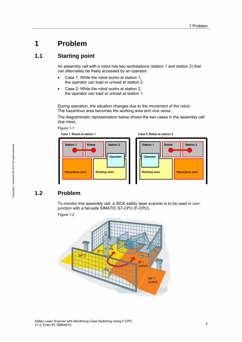
An assembly cell with a robot has two workstations (station 1 and station 2) that can alternately be freely accessed by an operator:
• Case 1: While the robot works at station 1, the operator can load or unload at station 2.
• Case 2: While the robot works at station 2, the operator can load or unload at station 1.
During operation, the situation changes due to the movement of the robot: The hazardous area becomes the working area and vice versa.
The diagrammatic representation below shows the two cases in the assembly cell (top view).
Figure 1-1
1.2 Problem
To monitor this assembly cell, a SICK safety laser scanner is to be used in con-junction with a fail-safe SIMATIC S7-CPU (F-CPU).
Figure 1-2

2 Solution
8 Safety Laser Scanner with Monitoring Case Switching Using F-CPU
V1.0, Entry ID: 58804919
Co
pyr
igh
t
Sie
me
ns
AG
20
12
All
righ
ts r
ese
rve
d
2 Solution
2.1 Overview
2.1.1 Core components
A SICK safety laser scanner is operated on a fail-safe SIMATIC controller via PROFINET.
The following figure schematically shows the most important components of the application example:
• F-CPU (IO controller) with central I/O (DI, F-DI, F-DO)
• Safety laser scanner (IO device), connected via PROFINET on a distributed basis
Figure 2-1

2 Solution
Safety Laser Scanner with Monitoring Case Switching Using F-CPU V1.0, Entry ID: 58804919 9
Co
pyr
igh
t
Sie
me
ns
AG
20
12
All
righ
ts r
ese
rve
d
2.1.2 Core functionality
The following functions are implemented in the application example:
• Switching a machine (*1)
• Monitoring changing hazardous areas:
– Stop of the machine when the active protective field is violated
– Switching between two monitoring cases (*2)
• Reintegration of passivated F-I/O (*3)
In the safety laser scanner, two field sets are configured for the two monitoring cases:
• Field set 1: Protective field 1 (SF1) and warning field 1 (WF1)
• Field set 2: Protective field 2 (SF2) and warning field 2 (WF2)
(*1): The machine is simulated with an indicator light.
(*2): The application example is prepared for four monitoring cases.
(*3): F-DI, F-DO, safety laser scanner

2 Solution
10 Safety Laser Scanner with Monitoring Case Switching Using F-CPU
V1.0, Entry ID: 58804919
Co
pyr
igh
t
Sie
me
ns
AG
20
12
All
righ
ts r
ese
rve
d
2.2 Hardware and software components used
The application example was created with the following components.
2.2.1 Hardware components
Manufactured by Siemens
Table 2-1
Component Type Qty. Order no.
DIN rail Length: 585 mm 1 6ES7390-1AF85-0AA0
Power supply PS307 24V/5A 1 6ES7307-1EA01-0AA0
Fail-safe S7-CPU CPU 315F-2PN/DP 1 6ES7315-2FJ14-0AB0
SIMATIC Micro Memory Card 2 MB 1 6ES7953-8LL20-0AA0
Digital input module (DI) SM 321; DI 16 x 24 VDC 1 6ES7321-1BH02-0AA0
Fail-safe digital input module (F-DI) SM 326; DI 24 x 24 VDC 1 6ES7326-1BK02-0AB0
Fail-safe digital output module (F-DO) SM 326; DO 8 x 24 VDC/2 A PM 1 6ES7326-2BF41-0AB0
Front connector for DI 20-pin 1 6ES7392-1BJ00-0AA0
Front connector for F-DI, F-DO 40-pin 2 6ES7392-1BM00-0AA0
Sensor for monitoring case 1, 2 (NC)
SIRIUS mechanical position switch / safety position switch
2 3SE5 / 3SF1
Pushbutton for start, acknowledgement (NO)
SIRIUS pushbutton, indicator light 2 3SB2, 3SB3, 3SF5
Pushbutton for stop (NC) SIRIUS pushbutton, indicator light 1 3SB2, 3SB3, 3SF5
Indicator light SIRIUS pushbutton, indicator light 1 3SB2, 3SB3, 3SF5
Manufactured by SICK
Table 2-2
Component Type Qty. Part no.
SICK S3000 PROFINET IO safety laser scanner
Type: S3000-M Advanced Device type: S30A-6111CP
1 1045652
Plug connector with cable for S3000 PROFINET IO
Device type: Sx1A-B0201L 1 2049575
Connecting cable to connect the configu-ration port to the serial interface of the PC
--- 1 6021195
2 Solution
Safety Laser Scanner with Monitoring Case Switching Using F-CPU V1.0, Entry ID: 58804919 11
Co
pyr
igh
t
Sie
me
ns
AG
20
12
All
righ
ts r
ese
rve
d
2.2.2 Software components
Siemens software components
Table 2-3
Component Type Order no. Note
STEP 7 Professional V11 SP1, Update 2 6ES7822-1A.01-.. ---
STEP 7 Safety Advanced V11 --- 6ES7833-1FA11-0YA5 ---
SICK software components
Table 2-4
Component Type Order no. Note
Configuration & Diagnostic Software (CDS)
CDS V3.6.6 --- Supplied with the laser scanner, can alternatively be downloaded at /1/
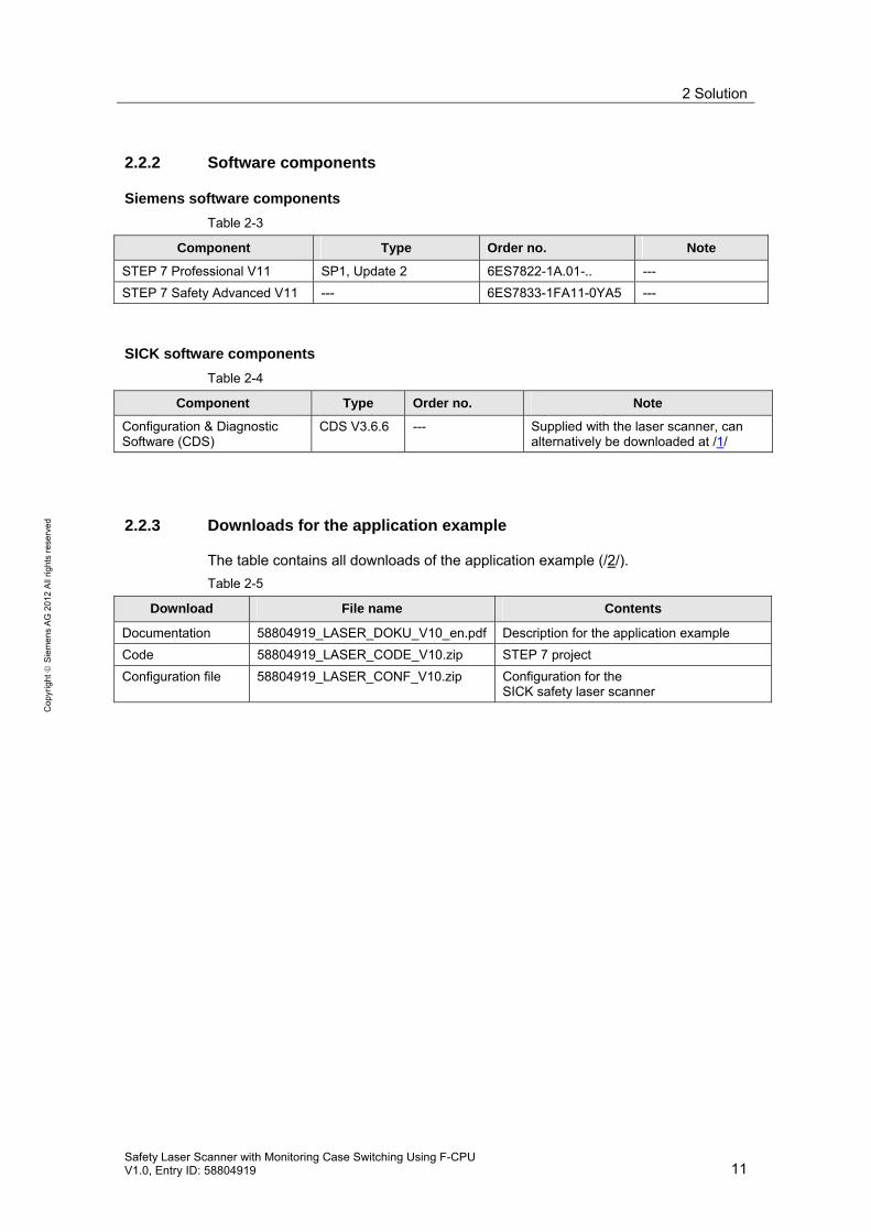
2.2.3 Downloads for the application example
The table contains all downloads of the application example (/2/).
Table 2-5
Download File name Contents
Documentation 58804919_LASER_DOKU_V10_en.pdf Description for the application example
Code 58804919_LASER_CODE_V10.zip STEP 7 project
Configuration file 58804919_LASER_CONF_V10.zip Configuration for the SICK safety laser scanner

2 Solution
12 Safety Laser Scanner with Monitoring Case Switching Using F-CPU
V1.0, Entry ID: 58804919
Co
pyr
igh
t
Sie
me
ns
AG
20
12
All
righ
ts r
ese
rve
d
2.3 Advantages
SIMATIC Safety Integrated for Factory Automation
In SIMATIC, standard applications and safety-related applications can be imple-mented with a single system (hardware and software):
This has the following advantages:
• One controller for both applications
• Uniform engineering for both applications
• One bus system for communication for both applications
• Uniform, centrally accessible diagnostics for both applications
• Easy connection of the safety program to the standard user program
SICK S3000 PROFINET IO laser scanner (/1/)
The laser scanner allows flexible protection of hazardous areas:
• Ideal cost-effective, customized solution for direct integration into bus systems
• Communicates all I/O signals directly with the network or the higher level con-trol, including detailed diagnosis
• Up to 8 protective/warning fields
• 3 scanning range variants, each with 4 or 8 protective fields
• Instructive acyclic diagnosis messages
• Simple process image
• Future-oriented and extendable
Examples of fields of application:
• Protection of machines with changing protection areas
• Entry/exit systems
• Hazardous area protection in robot cells and production systems
2.4 Required knowledge
The application example shows the principle of how a laser scanner can be oper-ated on an F-CPU. It does not describe details. Therefore, basic knowledge of the following topics is required:
• Software for SIMATIC controllers:
– STEP 7 V11 (/22/)
– STEP 7 Safety Advanced V11 (/9/)
• SIMATIC S7 modular controllers: S7-300 (/3/, /16/)
• Industrial communication: PROFINET (/20/)
• Safety laser scanners: SICK S3000 PROFINET IO (/1/)
3 SICK S3000 PROFINET IO Basics
Safety Laser Scanner with Monitoring Case Switching Using F-CPU V1.0, Entry ID: 58804919 13
Co
pyr
igh
t
Sie
me
ns
AG
20
12
All
righ
ts r
ese
rve
d
3 SICK S3000 PROFINET IO Basics The application example focuses on the use of a safety laser scanner for SIMATIC Safety Integrated for Factory Automation.
A safety laser scanner from SICK is used as an example.
This chapter describes the basics of the SICK S3000 PROFINET IO safety laser scanner (/1/).
3.1 Field of application
The S3000 PROFINET IO safety laser scanner is used for personnel and plant pro-tection. The laser scanner allows monitoring of hazardous areas on machines or vehicles.
Examples of applications:
• Protection of machines with changing hazardous areas
• Hazardous area protection in robot cells and production systems
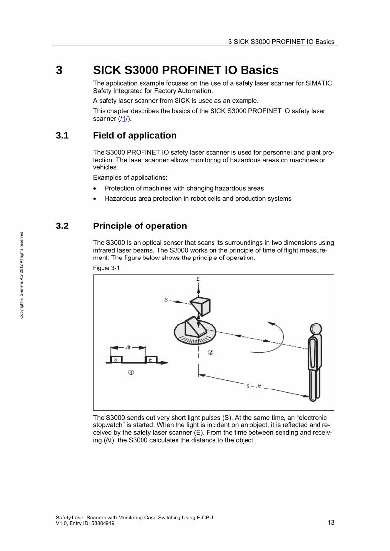
3.2 Principle of operation
The S3000 is an optical sensor that scans its surroundings in two dimensions using infrared laser beams. The S3000 works on the principle of time of flight measure-ment. The figure below shows the principle of operation.
Figure 3-1
The S3000 sends out very short light pulses (S). At the same time, an “electronic stopwatch” is started. When the light is incident on an object, it is reflected and re-ceived by the safety laser scanner (E). From the time between sending and receiv-ing (Δt), the S3000 calculates the distance to the object.

3 SICK S3000 PROFINET IO Basics
14 Safety Laser Scanner with Monitoring Case Switching Using F-CPU
V1.0, Entry ID: 58804919
Co
pyr
igh
t
Sie
me
ns
AG
20
12
All
righ
ts r
ese
rve
d
In the S3000, there is also a mirror rotating at a constant speed that deflects the light pulses so that they cover an arc of 190° (Figure 3-2). By determining the angle of rotation of the mirror, the S3000 determines the direction of the object.
From the measured distance and the direction of the object, the safety laser scan-ner determines the exact position of the object.
Figure 3-2
3.3 Field set and monitoring case
Protective field and warning field
The protective field (Figure 3-3, (1)) secures the hazardous area on a machine or vehicle. As soon as the safety laser scanner detects an object in the protective field, the S3000 switches the OSSD signal output (*1) to the off status (“0” signal) and thus initiates the shutdown of the machine or stop of the vehicle.
The warning field (Figure 3-3 , ((2)) can be defined so that the safety laser scanner detects an object before the actual hazardous area and, for example, triggers a warning signal.
Figure 3-3
(*1):
OSSD (output signal switching device): Signal output of the protective device that is used to stop the dangerous movement.

3 SICK S3000 PROFINET IO Basics
Safety Laser Scanner with Monitoring Case Switching Using F-CPU V1.0, Entry ID: 58804919 15
Co
pyr
igh
t
Sie
me
ns
AG
20
12
All
righ
ts r
ese
rve
d
Field set
Protective field and warning field form a pair, the so-called field set. With the aid of the Configuration & Diagnostic Software (CDS, /8/), these field sets are configured and transferred to the S3000. Up to eight field sets can be defined and saved in the S3000 PROFINET IO.
Monitoring case
With the S3000 safety laser scanner, you can define different monitoring cases to match the protective fields and warning fields to the situation on the machine. This allows situation-specific monitoring of changing hazardous areas, for example dur-ing the different production phases of a machine.
When configuring using the Configuration & Diagnostic Software (CDS, /8/), a monitoring case x is assigned a field set y (protective field y, warning field y).
Example
Figure 3-4 shows an example of hazardous area protection with two areas to be monitored. Two monitoring cases are defined in the robot cell shown in this figure:
• Monitoring case 1: Warning field 1 (WF1) and protective field 1 (SF1)
• Monitoring case 2: Warning field 2 (WF2) and protective field 2 (SF2)
Depending on where the robot is located in the robot cell, the respective monitoring case is active:
• The robot is located on the left: Monitoring case 2 is active
• The robot is located on the right: Monitoring case 1 is active
Figure 3-4
In the figure, the robot is located on the right of the robot cell, i.e. monitoring case 1 is active. This means:
• When the operator enters protective field 1, the robot will stop.
• The operator may enter protective field 2 and warning field 2.

3 SICK S3000 PROFINET IO Basics
16 Safety Laser Scanner with Monitoring Case Switching Using F-CPU
V1.0, Entry ID: 58804919
Co
pyr
igh
t
Sie
me
ns
AG
20
12
All
righ
ts r
ese
rve
d
3.4 Communication via PROFINET
The S3000 PROFINET IO is operated as an IO device on PROFINET. All input signals and output signals of the laser scanner are exchanged with the IO control-ler via the PROFINET interface.
Secure communication
Safety-related components and standard components can be operated together on PROFINET. This is enabled by PROFIsafe, an extension of PROFINET.
PROFIsafe defines how safety-related IO devices (e.g., a SICK safety laser scan-ner) securely communicate with safety-related IO controllers (e.g., a SIMATIC F-CPU) via a network.
Process image of the SIMATIC F-CPU
F-CPU and safety laser scanner cyclically exchange signals via the process image.
Figure 3-5
Examples of input signals of the laser scanner (F-CPU outputs):
• Number of the monitoring case
• Reset protective field
• Initialize
Examples of output signals of the laser scanner (F-CPU inputs):
• Protective field unoccupied
• Warning field unoccupied
• Contamination

4 Functional Mechanisms
Safety Laser Scanner with Monitoring Case Switching Using F-CPU V1.0, Entry ID: 58804919 17
Co
pyr
igh
t
Sie
me
ns
AG
20
12
All
righ
ts r
ese
rve
d
4 Functional Mechanisms
4.1 Functionality of the application example
4.1.1 Overview
The following functions are implemented in the application example:
• Switching a machine (*1)
• Monitoring changing hazardous areas:
– Stop of the machine when the active protective field is violated
– Switching between two monitoring cases (*2)
• Reintegration of passivated F-I/O (*3)
In the safety laser scanner, two field sets are configured for the two monitoring cases:
• Field set 1: Protective field 1 (SF1) and warning field 1 (WF1)
• Field set 2: Protective field 2 (SF2) and warning field 2 (WF2)
(*1): The machine is simulated with an indicator light.
(*2): The application example is prepared for four monitoring cases.
(*3): F-DI, F-DO, safety laser scanner
4.1.2 Start machine
The start of the machine depends on how the machine was previously stopped.
The following events cause the machine to stop:
• Stop pushbutton
• Error:
– Protective field violation
– Passivation (F-DI, F-DO, laser scanner)
– Error when switching the monitoring case
Start after: Stop pushbutton
The machine will only be started again when (AND):
• Start pushbutton pressed
• No error has occurred
See Figure 4-1.
4 Functional Mechanisms
18 Safety Laser Scanner with Monitoring Case Switching Using F-CPU
V1.0, Entry ID: 58804919
Co
pyr
igh
t
Sie
me
ns
AG
20
12
All
righ
ts r
ese
rve
d
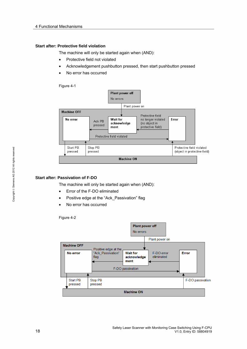
Start after: Protective field violation
The machine will only be started again when (AND):
• Protective field not violated
• Acknowledgement pushbutton pressed, then start pushbutton pressed
• No error has occurred
Figure 4-1
Start after: Passivation of F-DO
The machine will only be started again when (AND):
• Error of the F-DO eliminated
• Positive edge at the “Ack_Passivation” flag
• No error has occurred
Figure 4-2
4 Functional Mechanisms
Safety Laser Scanner with Monitoring Case Switching Using F-CPU V1.0, Entry ID: 58804919 19
Co
pyr
igh
t
Sie
me
ns
AG
20
12
All
righ
ts r
ese
rve
d
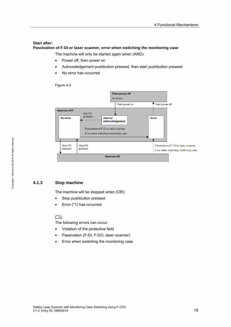
Start after: Passivation of F-DI or laser scanner, error when switching the monitoring case
The machine will only be started again when (AND):
• Power off, then power on
• Acknowledgement pushbutton pressed, then start pushbutton pressed
• No error has occurred
Figure 4-3
4.1.3 Stop machine
The machine will be stopped when (OR):
• Stop pushbutton pressed
• Error (*1) has occurred
(*1):
The following errors can occur:
• Violation of the protective field
• Passivation (F-DI, F-DO, laser scanner)
• Error when switching the monitoring case

4 Functional Mechanisms
20 Safety Laser Scanner with Monitoring Case Switching Using F-CPU
V1.0, Entry ID: 58804919
Co
pyr
igh
t
Sie
me
ns
AG
20
12
All
righ
ts r
ese
rve
d
4.1.4 Time relationships
The figure below shows the time relationships:
• Start and stop of the machine using pushbuttons
• Stop due to a violation of the active protective field
• Start when the active protective field is unoccupied again and acknowledge-ment has been made.
Explanation of the signals shown in Figure 4-4.
Table 4-1
Signal Hardware Explanations
START Start pushbutton Positive edge: Start the machine
STOP Stop pushbutton "0" Signal: Stop the machine
ACK Acknowledgement pushbutton Positive edge: Acknowledgement
OSSD Laser scanner “0” Signal: Protective field violation
ACTUATOR Machine (indicator light) ---
Time characteristic of the signals:
Figure 4-4
Explanation of the above times tx:
Time Explanations
t1 Start the machine
t2 Stop the machine
t3 Start the machine
t4 Violation of the active protective field: Stop the machine
t5 Protective field free again
t6 Machine cannot be started due to missing acknowledgement
t7 Acknowledgement
t8 Start the machine

4 Functional Mechanisms
Safety Laser Scanner with Monitoring Case Switching Using F-CPU V1.0, Entry ID: 58804919 21
Co
pyr
igh
t
Sie
me
ns
AG
20
12
All
righ
ts r
ese
rve
d
4.1.5 Monitoring case switching
Monitoring cases
Two monitoring cases are implemented in the application example. The monitoring cases are selected using two sensors (e.g., position switches):
• Sensor 1 has “0”, sensor 2 has “1”: Monitoring case 1 is selected
• Sensor 1 has “1”, sensor 2 has “0”: Monitoring case 2 is selected
Note: The application example can be extended to four monitoring cases. For this purpose, preparations were made in the code. To extend the application example, basically perform the following steps:
• Connect additional sensors for case switching (connection to F-DI)
• Configure additional monitoring cases and field sets (with CDS /8/)
Monitoring the case switching
Switching from monitoring case 1 to monitoring case 2 means:
• Sensor 1 changes from “0” to “1”
• Within the switching time, sensor 2 changes from “1” to “0”
The maximum permissible time (switching time) for switching between two monitor-ing cases is monitored by the F-CPU. The permissible switching time depends on the specific application. Therefore, the switching time can be parameterized in the application example.
Figure 4-5 shows the correlations for four sensors and switching from monitoring case 1 to monitoring case 2.
Figure 4-5

4 Functional Mechanisms
22 Safety Laser Scanner with Monitoring Case Switching Using F-CPU
V1.0, Entry ID: 58804919
Co
pyr
igh
t
Sie
me
ns
AG
20
12
All
righ
ts r
ese
rve
d
4.1.6 Reintegration of F-I/O
If an error occurs in a component of the F-I/O, this results in the passivation of this component. Once the error has been eliminated, the passivated component must be reintegrated.
In the application example, reintegration is implemented in different ways:
• F-DI and laser scanner: Reintegration without operator intervention
• F-DO: Reintegration with operator intervention (generation of a positive edge at the Ack_Passivation flag)

4 Functional Mechanisms
Safety Laser Scanner with Monitoring Case Switching Using F-CPU V1.0, Entry ID: 58804919 23
Co
pyr
igh
t
Sie
me
ns
AG
20
12
All
righ
ts r
ese
rve
d
4.2 Code description (STEP 7 project)
4.2.1 User program structure
Preliminary remark
The code contains the user program (STEP 7 project) for the F-CPU.
The user program consists of:
• Standard user program
• Safety program
Overview
Standard user program:
Figure 4-6
Safety program:
Figure 4-7
Program blocks of the standard user program
Table 4-2
Program block Function
Start_Stop_Machine Request to start or stop the machine
Program blocks of the safety program
Table 4-3
Program block Function
Safety Call of the following blocks:
• Reintegration
• Monitoring_Case_Switching
• On_Off_Machine
Reintegration Reintegration of passivated F-I/O
Monitoring_Case_Switching Monitoring case switching
On_Off_Machine Switching the machine (indicator light) on or off
Password for the safety program
A password for the safety program is not used in the code of the application exam-ple.

4 Functional Mechanisms
24 Safety Laser Scanner with Monitoring Case Switching Using F-CPU
V1.0, Entry ID: 58804919
Co
pyr
igh
t
Sie
me
ns
AG
20
12
All
righ
ts r
ese
rve
d
4.2.2 Function circuit diagram
The figure shows the following correlations:
• Hardware / user program
• Standard user program / safety program
Figure 4-8
Explanations
NO: Pushbutton (NO)
NC: Pushbutton (NC)
Contents of the legends in the figure: Variables of the user program

4 Functional Mechanisms
Safety Laser Scanner with Monitoring Case Switching Using F-CPU V1.0, Entry ID: 58804919 25
Co
pyr
igh
t
Sie
me
ns
AG
20
12
All
righ
ts r
ese
rve
d
4.2.3 Program block: Start_Stop_Machine
Program
Standard user program
Function
The block generates a request to start or stop the machine. The request is evalu-ated in the safety program.
The block evaluates:
• Start pushbutton
• Stop pushbutton
• “Enable” signal from the safety program (On_Off_Machine)
The block provides to the safety program (On_Off_Machine):
• “Condition” signal
Parameters of the function block
Figure 4-9
Table 4-4
Parameter Declaration Type Description
--- --- --- ---
Implementation
Description: See chapter 4.2.5.
It describes the interaction of the following two program blocks:
• Start_Stop_Machine
• On_Off_Machine

4 Functional Mechanisms
26 Safety Laser Scanner with Monitoring Case Switching Using F-CPU
V1.0, Entry ID: 58804919
Co
pyr
igh
t
Sie
me
ns
AG
20
12
All
righ
ts r
ese
rve
d
4.2.4 Program block: On_Off_Machine
Program
Safety program
Function
The block implements the start or stop of the machine.
The block evaluates:
• Acknowledgement pushbutton
• “Flag_Condition” signal from the standard user program (Start_Stop_Machine)
• “OSSD” signal from the laser scanner
The block provides to the standard user program:
• “Enable” signal
Parameters of the function block
Figure 4-10
Table 4-5
Parameter Declaration Type Description
Ack IN Bool Signal from the acknowledgement pushbutton
OSSD IN Bool Safety-related signal from the laser scanner. “0” signal: Active protective field violated
Condition (*1) IN Bool The signal is generated in the standard user program. “0” signal: Prevents the machine from starting.
Actuator OUT Bool Signal to the machine (indicator light)
(*1):
“Condition” must be transferred to the safety program via a flag (“Condition_Flag”).
Implementation
Description: See chapter 4.2.5.
It describes the interaction of the following two program blocks:
• Start_Stop_Machine
• On_Off_Machine

4 Functional Mechanisms
Safety Laser Scanner with Monitoring Case Switching Using F-CPU V1.0, Entry ID: 58804919 27
Co
pyr
igh
t
Sie
me
ns
AG
20
12
All
righ
ts r
ese
rve
d
4.2.5 Interaction of Start_Stop_Machine / On_Off_Machine
The figure shows the interaction of the following two blocks:
• Start_Stop_Machine
• On_Off_Machine
Description of functionality:
• See chapter 4.1.2 and 4.1.3.
Figure 4-11
Explanations of the figure
For the flipflop (SR), reset (R) has priority.
Meaning of the variables:
Table 4-6
Variable Explanation
Start Positive edge: Request to start the machine
Stop “0” signal: Stop of the machine
Ack Negative edge: The machine can be started again
Enable “0” signal: Prevents the machine from starting “1” signal: The machine can be started
OSSD “0” signal: Stop of the machine
Condition (*1) “0” signal: Prevents the machine from starting
Actuator "1" signal: Signal to the machine (indicator light)
(*1):
“Condition” must be transferred to the safety program via a flag (“Condition_Flag”).
4 Functional Mechanisms
28 Safety Laser Scanner with Monitoring Case Switching Using F-CPU
V1.0, Entry ID: 58804919
Co
pyr
igh
t
Sie
me
ns
AG
20
12
All
righ
ts r
ese
rve
d
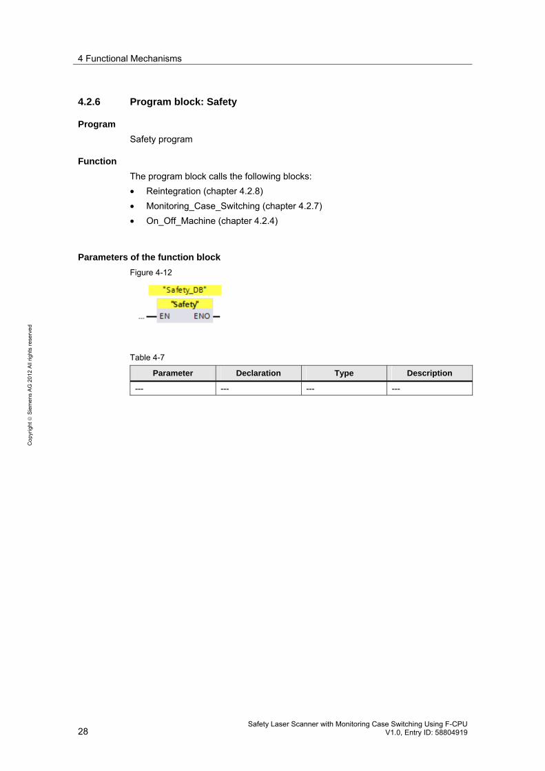
4.2.6 Program block: Safety
Program
Safety program
Function
The program block calls the following blocks:
• Reintegration (chapter 4.2.8)
• Monitoring_Case_Switching (chapter 4.2.7)
• On_Off_Machine (chapter 4.2.4)
Parameters of the function block
Figure 4-12
Table 4-7
Parameter Declaration Type Description
--- --- --- ---

4 Functional Mechanisms
Safety Laser Scanner with Monitoring Case Switching Using F-CPU V1.0, Entry ID: 58804919 29
Co
pyr
igh
t
Sie
me
ns
AG
20
12
All
righ
ts r
ese
rve
d
4.2.7 Program block: Monitoring_Case_Switching
Program
Safety program
Function
Monitoring case switching
This block implements monitoring case switching of max. four monitoring cases.
For this purpose, the F-CPU reads in the status of max. 4 sensors, derives the monitoring case number from this information and writes the respective control sig-nals (A1, A2, B1, B2) to the laser scanner. The laser scanner activates the field set that is allocated to the monitoring case number.
One sensor (NC) is allocated to each monitoring case:
• Monitoring case 1: Sensor 1
• Monitoring case 2: Sensor 2
• Monitoring case 3: Sensor 3
• Monitoring case 4: Sensor 4
Monitoring case x is selected when the following applies (AND):
• The sensor for monitoring case x is active (“0” signal)
• All other sensors are not active (“1” signal)
Switching time monitoring
The time that is required to switch between two monitoring cases (switching time) is monitored. The switching time can be parameterized on the block.
The following conditions are monitored:
• After switching a sensor from “0” to “1”, another sensor must switch from “1” to “0” within the monitoring time.
• After switching, exactly one of the following cases must be present:
– Sensor 1 has “0” signal and all other sensors have “1” signal
– Sensor 2 has “0” signal and all other sensors have “1” signal
– Sensor 3 has “0” signal and all other sensors have “1” signal
– Sensor 4 has “0” signal and all other sensors have “1” signal
If the above conditions are not met, an error has occurred.
Response in the event of an error
The control signals (from the F-CPU to the laser scanner) for switching the monitor-ing cases (A1, A2, B1, B2) are deleted (“0”).
In the laser scanner, the deletion of the control signals (“0”) causes the following actions:
• Reset of the OSSD bit (signal from the laser scanner to the F-CPU): This causes the stop of the machine via the F-CPU.
• Error display on the laser scanner: “Incorrect operation of the control inputs” (see chapter 8.8).

4 Functional Mechanisms
30 Safety Laser Scanner with Monitoring Case Switching Using F-CPU
V1.0, Entry ID: 58804919
Co
pyr
igh
t
Sie
me
ns
AG
20
12
All
righ
ts r
ese
rve
d
Implementation in the application example
Two monitoring cases are implemented in the application example. The code is prepared for max. 4 monitoring cases. To use additional monitoring cases, perform the following steps:
• Configure the additional field sets and allocate the monitoring cases using the CDS (/8/)
• Interconnect the additional sensors for the monitoring cases at the call inter-face of the program block
Parameters of the function block
Figure 4-13
Table 4-8
Parameter Declaration Type Description
sensor_case_1 IN Bool Sensor for monitoring case 1 (*1)
sensor_case_2 IN Bool Sensor for monitoring case 2 (*1)
sensor_case_3 IN Bool Sensor for monitoring case 3 (*1)
sensor_case_4 IN Bool Sensor for monitoring case 4 (*1)
switch_time_max IN Time Maximum permissible switching time
case_bit_A1 OUT Bool
case_bit_A2 OUT Bool
case_bit_B1 OUT Bool
case_bit_B2 OUT Bool
Control signals for switching the monitoring cases: Monitoring case number (*2)
error_switch_time OUT Bool Error when monitoring the switching time
(*1): Non-existent sensors must be interconnected with a “1” signal.

4 Functional Mechanisms
Safety Laser Scanner with Monitoring Case Switching Using F-CPU V1.0, Entry ID: 58804919 31
Co
pyr
igh
t
Sie
me
ns
AG
20
12
All
righ
ts r
ese
rve
d
(*2): The following table shows the allocation:
Table 4-9
Sensor for monitoring case Control signals from F-CPU to laser scanner
sensor_ case_1
sensor_case_2
sensor_ case_3
sensor_case_4
case_ bit_B2
case_ bit_B1
case_ bit_A2
case_ bit_A1
Monitoring case
0 1 1 1 0 1 0 1 1
1 0 1 1 0 1 1 0 2
1 1 0 1 1 0 0 1 3
1 1 1 0 1 0 1 0 4
4.2.8 Program block: Reintegration
Program
Safety program
Function
Components of the F-I/O (F-DI, F-DO, laser scanner) can passivate.
Examples of events that cause passivation:
• Wire break on the F-DO
• Missing power supply on the F-DI
• No communication between laser scanner and F-CPU
The block reintegrates passivated components. Reintegration is implemented dif-ferently in the code:
• Reintegration without operator intervention
– F-DI
– Laser scanner
• Reintegration with operator intervention (*1)
– F-DO
(*1): After passivation, a positive edge must be generated at a flag bit (Ack_Passivation) (chapter 8.6).
Parameters of the function block
Figure 4-14
Table 4-10
Parameter Declaration Type Description
--- --- --- ---

5 Configuration of the SIMATIC Components
32 Safety Laser Scanner with Monitoring Case Switching Using F-CPU
V1.0, Entry ID: 58804919
Co
pyr
igh
t
Sie
me
ns
AG
20
12
All
righ
ts r
ese
rve
d
5 Configuration of the SIMATIC Components
5.1 Preliminary remark
This chapter describes the most important settings that were made in the applica-tion example for the SIMATIC components:
• Settings in the Device Configuration of STEP 7
• Settings in the Safety Administration of STEP 7
Note
It is not necessary to make the settings in the application example, they are already included in the code. This chapter is for information only.
5.2 Requirements
The SICK safety laser scanner must be integrated into the STEP 7 hardware cata-log. The laser scanner comes with a CD-ROM that includes the device master file (GSDML file). New IO devices installed via GSDML files can be found in “Other field devices” in the hardware catalog.
Figure 5-1

5 Configuration of the SIMATIC Components
Safety Laser Scanner with Monitoring Case Switching Using F-CPU V1.0, Entry ID: 58804919 33
Co
pyr
igh
t
Sie
me
ns
AG
20
12
All
righ
ts r
ese
rve
d
5.3 Device configuration
Open the Device configuration as follows:
• Start the TIA Portal
• Open the project view
• Open the “laser_scanner_03” project
• In the project tree: Open “PLC_1 (CPU 315-F-2 PN/DP)” device > Open the Device configuration
5.3.1 PROFINET network
Actions in the Device configuration:
• In the workspace: Open the Network view
• In the Inspector window: Open the Network overview
Result:
Figure 5-2
5 Configuration of the SIMATIC Components
34 Safety Laser Scanner with Monitoring Case Switching Using F-CPU
V1.0, Entry ID: 58804919
Co
pyr
igh
t
Sie
me
ns
AG
20
12
All
righ
ts r
ese
rve
d
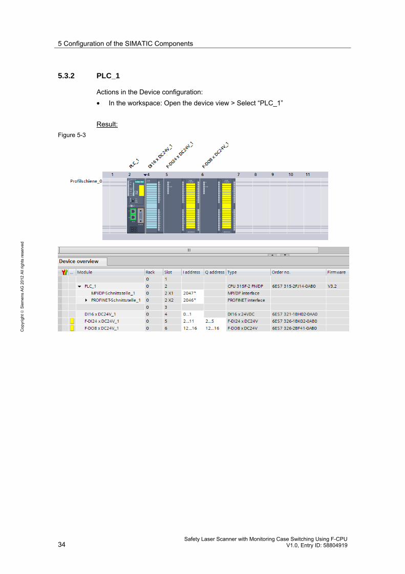
5.3.2 PLC_1
Actions in the Device configuration:
• In the workspace: Open the device view > Select “PLC_1”
Result:
Figure 5-3

5 Configuration of the SIMATIC Components
Safety Laser Scanner with Monitoring Case Switching Using F-CPU V1.0, Entry ID: 58804919 35
Co
pyr
igh
t
Sie
me
ns
AG
20
12
All
righ
ts r
ese
rve
d
5.3.3 S3000
Actions in the Device configuration:
• In the workspace:
– Open the device view > Select “S3000”
– In the device overview: Select “S3000 In/Out_1”
• In the Inspector window:
– Select the “Properties” tab > Select “PROFIsafe”
Result:
Figure 5-4
The PROFIsafe address (F_Dest_Add) of the laser scanner is read out here.
CDS (/8/) is used to enter the value in the configuration file of the laser scanner (chapter 6.3).

5 Configuration of the SIMATIC Components
36 Safety Laser Scanner with Monitoring Case Switching Using F-CPU
V1.0, Entry ID: 58804919
Co
pyr
igh
t
Sie
me
ns
AG
20
12
All
righ
ts r
ese
rve
d
5.3.4 F-CPU
Actions in the Device configuration:
• In the workspace:
– Open the device view > Select “PLC_1”
• In the Inspector window:
– Select the “Properties” tab
– Select “Fail-safe” (see result 1)
– Select “F-parameter” (see result 2)
Result 1:
Figure 5-5
F-monitoring time for central F-I/O: 150 ms (Default)
Result 2:
Figure 5-6
F-monitoring time for F-I/O of this interface: 150 ms (Default)

5 Configuration of the SIMATIC Components
Safety Laser Scanner with Monitoring Case Switching Using F-CPU V1.0, Entry ID: 58804919 37
Co
pyr
igh
t
Sie
me
ns
AG
20
12
All
righ
ts r
ese
rve
d
5.3.5 F-DI
Actions in the Device configuration:
In the workspace:
• Open the device view > Select “F-DI24 xDC24V_1”
In the Inspector window:
• Select the “Properties” tab
• Select “F-parameter” (see result 1)
• “DI parameter” > “Supply group 1Vs/3Vs”) (see result 2)
• “DI parameter” > “Supply group 2Vs/4Vs”) (see result 3)
Result 1:
Figure 5-7
On the F-DI, the F-destination address is set on the DIP switch.

5 Configuration of the SIMATIC Components
38 Safety Laser Scanner with Monitoring Case Switching Using F-CPU
V1.0, Entry ID: 58804919
Co
pyr
igh
t
Sie
me
ns
AG
20
12
All
righ
ts r
ese
rve
d
Result 2:
Figure 5-8
Settings:
• Internal sensor supply / short circuit test activated
• Channel 0,12: 1oo1 evaluation
• Channel 1,13: 1oo1 evaluation
• All other channels: Not activated
Channel assignment:
• Channel 0: Sensor for monitoring case 1
• Channel 1: Sensor for monitoring case 2

5 Configuration of the SIMATIC Components
Safety Laser Scanner with Monitoring Case Switching Using F-CPU V1.0, Entry ID: 58804919 39
Co
pyr
igh
t
Sie
me
ns
AG
20
12
All
righ
ts r
ese
rve
d
Result 3:
Figure 5-9
Settings:
• Internal sensor supply / short circuit test not activated
• All channels: Not activated

5 Configuration of the SIMATIC Components
40 Safety Laser Scanner with Monitoring Case Switching Using F-CPU
V1.0, Entry ID: 58804919
Co
pyr
igh
t
Sie
me
ns
AG
20
12
All
righ
ts r
ese
rve
d
5.3.6 F-DO
Actions in the Device configuration:
In the workspace:
• Open the device view > Select “F-DO8 xDC24V_1”
In the Inspector window:
• Select the “Properties” tab
• Select “F-parameter” (see result 1)
• Select “DO parameter” (see result 2)
Result 1:
Figure 5-10
On the F-DO, the F-destination address is set on the DIP switch.

5 Configuration of the SIMATIC Components
Safety Laser Scanner with Monitoring Case Switching Using F-CPU V1.0, Entry ID: 58804919 41
Co
pyr
igh
t
Sie
me
ns
AG
20
12
All
righ
ts r
ese
rve
d
Result 2:
Figure 5-11
Settings:
• Channel 0: Activated
• All other channels: Not activated
Channel assignment:
• Channel 0: Machine (indicator light)

5 Configuration of the SIMATIC Components
42 Safety Laser Scanner with Monitoring Case Switching Using F-CPU
V1.0, Entry ID: 58804919
Co
pyr
igh
t
Sie
me
ns
AG
20
12
All
righ
ts r
ese
rve
d
5.4 Safety Administration
Open the Safety Administration as follows:
• Start the TIA Portal
• Open the project view
• Open the “laser_scanner_03” project
• In the project tree:
– Open the “PLC_1 (CPU 315-F-2 PN/DP)” device
– Open the Safety Administration
• In the workspace, select “F-runtime groups”
Result:
Figure 5-12
(1): Define the F-runtime group
(2): Set the monitoring time for the F-runtime group
1
2

6 Configuration of the SICK Laser Scanner
Safety Laser Scanner with Monitoring Case Switching Using F-CPU V1.0, Entry ID: 58804919 43
Co
pyr
igh
t
Sie
me
ns
AG
20
12
All
righ
ts r
ese
rve
d
6 Configuration of the SICK Laser Scanner
6.1 Preliminary remark
This chapter describes the most important settings that were made in the applica-tion example for the SICK safety laser scanner:
• Settings with the Configuration & Diagnostic Software (CDS, /8/)
Note
It is not necessary to make the settings in the application example, they are already included in the configuration file. This chapter is for information only.
6.2 Requirements
For the requirements, see /1/, /8/.
Configuration & Diagnostic Software (CDS)
For the configuration, the laser scanner must be connected to the PG/PC. The CDS must be installed on the PG/PC.
The CDS can be used to configure all available parameters of the S3000 and de-fine the field geometries of the protective fields and warning fields.
The result of the configuration is stored in a configuration file (name.skp). The con-figuration file is downloaded to the laser scanner.

6 Configuration of the SICK Laser Scanner
44 Safety Laser Scanner with Monitoring Case Switching Using F-CPU
V1.0, Entry ID: 58804919
Co
pyr
igh
t
Sie
me
ns
AG
20
12
All
righ
ts r
ese
rve
d
Configuration of the laser scanner
For the application example, the configuration was performed via the local serial in-terface of the laser scanner.
Figure 6-1
Figure 6-2 shows an example of the user interface of the Configuration & Diagnos-tic Software (CDS).
Figure 6-2
6 Configuration of the SICK Laser Scanner
Safety Laser Scanner with Monitoring Case Switching Using F-CPU V1.0, Entry ID: 58804919 45
Co
pyr
igh
t
Sie
me
ns
AG
20
12
All
righ
ts r
ese
rve
d
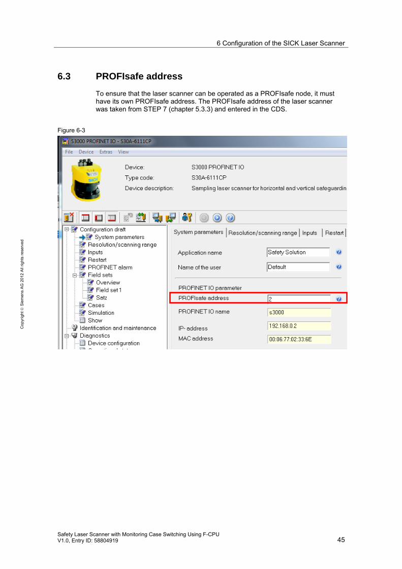
6.3 PROFIsafe address
To ensure that the laser scanner can be operated as a PROFIsafe node, it must have its own PROFIsafe address. The PROFIsafe address of the laser scanner was taken from STEP 7 (chapter 5.3.3) and entered in the CDS.
Figure 6-3

6 Configuration of the SICK Laser Scanner
46 Safety Laser Scanner with Monitoring Case Switching Using F-CPU
V1.0, Entry ID: 58804919
Co
pyr
igh
t
Sie
me
ns
AG
20
12
All
righ
ts r
ese
rve
d
6.4 Inputs
Two monitoring cases are implemented in the application example, four monitoring cases are prepared. Therefore, the “Input A-B” case is configured.
Figure 6-4
6 Configuration of the SICK Laser Scanner
Safety Laser Scanner with Monitoring Case Switching Using F-CPU V1.0, Entry ID: 58804919 47
Co
pyr
igh
t
Sie
me
ns
AG
20
12
All
righ
ts r
ese
rve
d
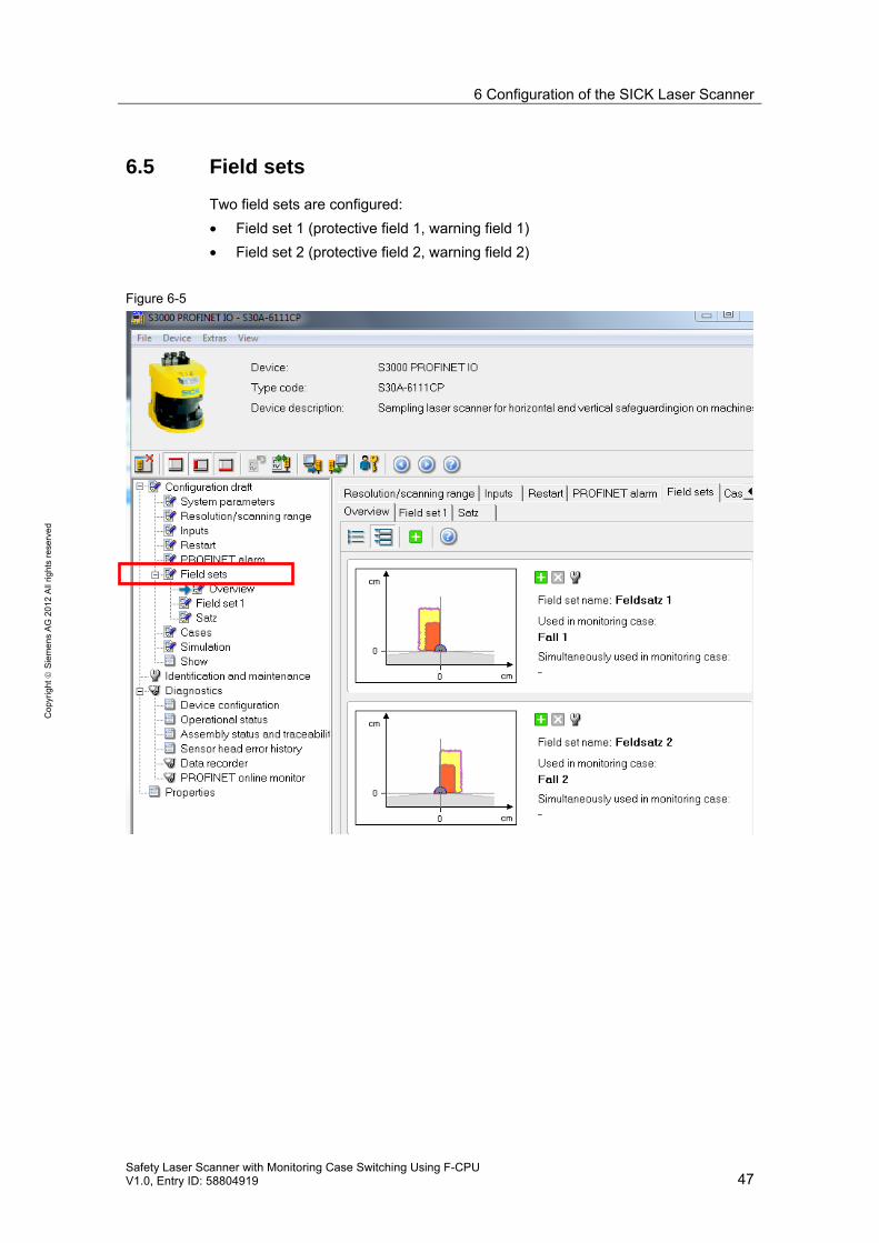
6.5 Field sets
Two field sets are configured:
• Field set 1 (protective field 1, warning field 1)
• Field set 2 (protective field 2, warning field 2)
Figure 6-5

6 Configuration of the SICK Laser Scanner
48 Safety Laser Scanner with Monitoring Case Switching Using F-CPU
V1.0, Entry ID: 58804919
Co
pyr
igh
t
Sie
me
ns
AG
20
12
All
righ
ts r
ese
rve
d
6.6 Monitoring cases
Two monitoring cases are configured:
• Monitoring case 1 with field set 1
• Monitoring case 2 with field set 2
Figure 6-6
6.7 Restart
The “without restart interlock” case is configured.
In the code (STEP 7 project), a restart interlock is implemented in the user program of the F-CPU.

7 Installation and Commissioning
Safety Laser Scanner with Monitoring Case Switching Using F-CPU V1.0, Entry ID: 58804919 49
Co
pyr
igh
t
Sie
me
ns
AG
20
12
All
righ
ts r
ese
rve
d
7 Installation and Commissioning
7.1 Overview of the steps
The following steps are necessary to install the application example:
• Load the downloads to the PG/PC:
– Code (STEP 7 project) for the F-CPU
– Configuration file for the laser scanner
• Install the hardware:
– SIMATIC components
– SICK safety laser scanner
• Create a defined initial state:
– F-CPU
– Laser scanner
• Download the code to the F-CPU
• For the laser scanner: Assign the IP address and device name
• Download the configuration file to the laser scanner
The following chapters describe the steps.
7.2 Loading the downloads to the PG/PC
The downloads for the application example are listed in chapter 2.2.3.
7.2.1 Code for the F-CPU
To install the code (STEP 7 project) on the PG/PC, the following actions are nec-essary:
• Download the “58804919_LASER_CODE_V10.zip” code to any directory on the PG/PC.
• Unzip the file.
7.2.2 Configuration file for the laser scanner
To install the configuration file on the PG/PC, the following actions are necessary:
• Download the “58804919_LASER_CONF_V10.zip” configuration file to any directory on the PG/PC.
• Unzip the file.

7 Installation and Commissioning
50 Safety Laser Scanner with Monitoring Case Switching Using F-CPU
V1.0, Entry ID: 58804919
Co
pyr
igh
t
Sie
me
ns
AG
20
12
All
righ
ts r
ese
rve
d
7.3 Installing the hardware
For the necessary hardware components, please refer to chapter 2.2.1.
NOTICE Follow the installation guidelines for PROFINET (/4/), SICK laser scanner (/1/) and SIMATIC S7-300 (/3/, /16/). Refer to the relevant manuals.
7.3.1 Installation
The table shows the procedure to install the hardware.
Table 7-1
No. Hardware Action
1. F-CPU and MMC Delete the SIMATIC Micro Memory Card (MMC) for the F-CPU and insert the MMC into the F-CPU.
2. F-DI Set the PROFIsafe address on the DIP switch (*1)
3. F-DO Set the PROFIsafe address on the DIP switch (*1)
4. S7-300 mounting rail Mount the following devices on the mounting rail: PS, F-CPU, DI, F-DI, F-DO
5. DI Wire the 3 pushbuttons
6. F-DI Wire the 2 sensors
7. F-DO Wire the indicator light
8. PROFINET cable Connect:
• F-CPU to laser scanner
• F-CPU to PG/PC.
9. Power supply (PS) Complete all necessary connections:
• For the SIMATIC components
• For the laser scanner
(*1):
The PROFIsafe addresses are automatically assigned when configuring the fail-safe signal modules in STEP 7:
• F-DI: See chapter 5.3.5
• F-DO: See chapter 5.3.6

7 Installation and Commissioning
Safety Laser Scanner with Monitoring Case Switching Using F-CPU V1.0, Entry ID: 58804919 51
Co
pyr
igh
t
Sie
me
ns
AG
20
12
All
righ
ts r
ese
rve
d
7.3.2 Overview of the configuration
The figure schematically shows the configuration of the application example.
Figure 7-1
7 Installation and Commissioning
52 Safety Laser Scanner with Monitoring Case Switching Using F-CPU
V1.0, Entry ID: 58804919
Co
pyr
igh
t
Sie
me
ns
AG
20
12
All
righ
ts r
ese
rve
d
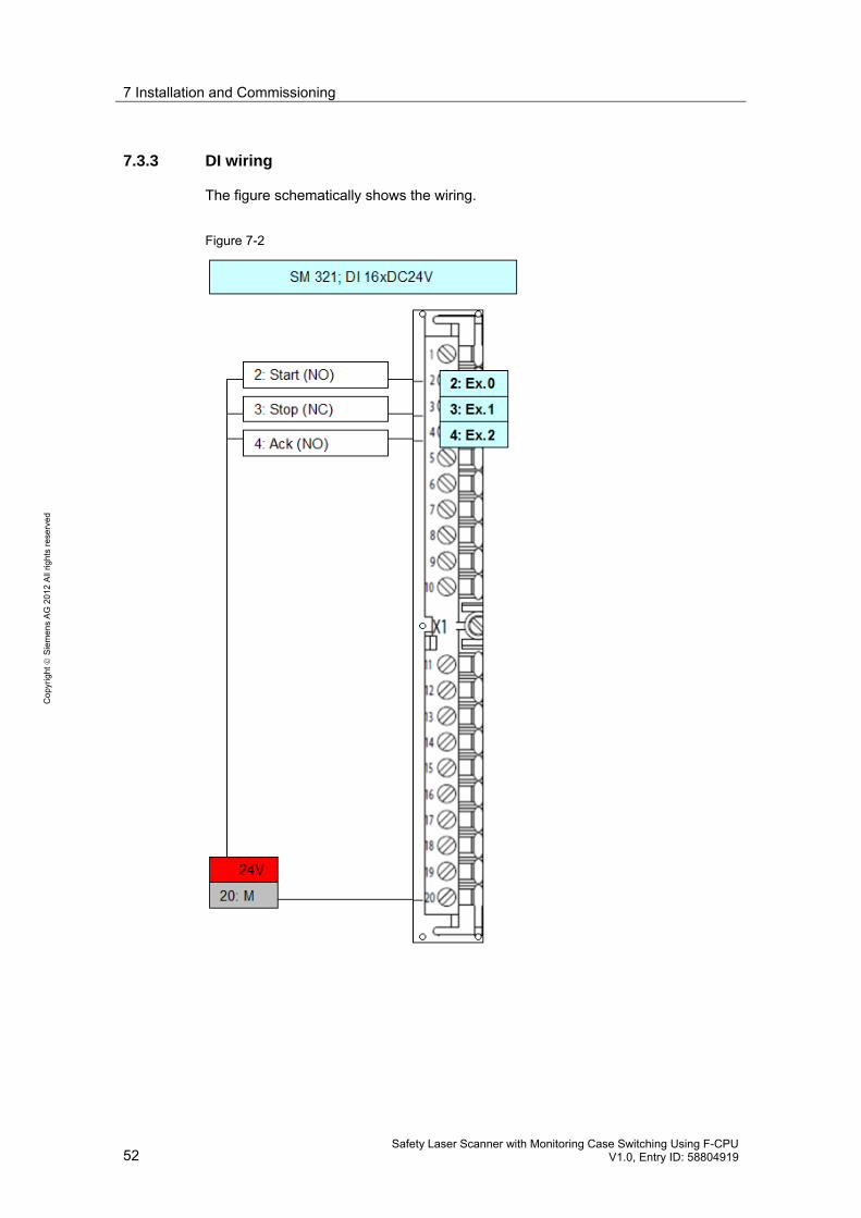
7.3.3 DI wiring
The figure schematically shows the wiring.
Figure 7-2
7 Installation and Commissioning
Safety Laser Scanner with Monitoring Case Switching Using F-CPU V1.0, Entry ID: 58804919 53
Co
pyr
igh
t
Sie
me
ns
AG
20
12
All
righ
ts r
ese
rve
d
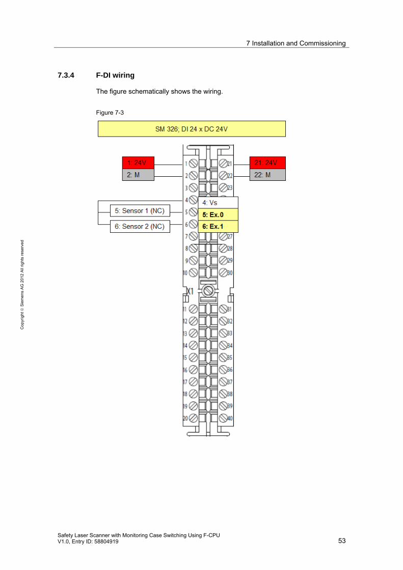
7.3.4 F-DI wiring
The figure schematically shows the wiring.
Figure 7-3
7 Installation and Commissioning
54 Safety Laser Scanner with Monitoring Case Switching Using F-CPU
V1.0, Entry ID: 58804919
Co
pyr
igh
t
Sie
me
ns
AG
20
12
All
righ
ts r
ese
rve
d
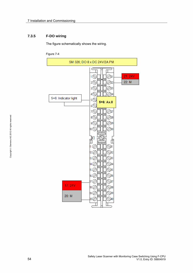
7.3.5 F-DO wiring
The figure schematically shows the wiring.
Figure 7-4

7 Installation and Commissioning
Safety Laser Scanner with Monitoring Case Switching Using F-CPU V1.0, Entry ID: 58804919 55
Co
pyr
igh
t
Sie
me
ns
AG
20
12
All
righ
ts r
ese
rve
d
7.4 Setting the F-CPU to the initial state
Initial state means:
• F-CPU has the factory setting
• SIMATIC Micro Memory Card (MMC) is empty (deleted)
Prerequisite:
• PG/PC is connected to F-CPU via Ethernet
• STEP 7 V11 is installed on PG/PC
Restore the F-CPU to factory setting
Prerequisite:
• No MMC is inserted in the F-CPU.
• The F-CPU is in STOP mode (mode selector in position STOP)
Procedure:
• Select in the project tree the F-CPU
• Select in the toolbar the "Go online" button
• Open the online and diagnostics view of the F-CPU
• Select: “Functions” > “Reset to factory settings”
• Select the “Reset” button
Result:
• RAM, internal load memory and all operand areas have been deleted.
• All parameters have been reset to their default values.
• The diagnostic buffer and the time has been deleted.
• The IP address and the PROFINET device name has been deleted.
Display in “Accessible Nodes” for the F-CPU:
Table 7-2
Device Device type Type Address MAC address
Accessible device S7-300 ISO --- 00-1B-1B-17-4C-3D (example)

7 Installation and Commissioning
56 Safety Laser Scanner with Monitoring Case Switching Using F-CPU
V1.0, Entry ID: 58804919
Co
pyr
igh
t
Sie
me
ns
AG
20
12
All
righ
ts r
ese
rve
d
Delete the MMC
Procedure:
• Insert the MMC into the programming device
• In the project tree:
– Select: "SIMATIC Card Reader" > "Internal prommer"
– Select "Micro Memory Card"
• In the Project menu, select: “SIMATIC Card Reader” > “Format memory card”
Insert the empty MMC
Prerequisite:
• The F-CPU is in STOP mode (mode selector in position STOP)
Procedure:
• Switch off the power supply of the F-CPU
• Insert the MMC into the F-CPU
• Switch on the power supply of the F-CPU

7 Installation and Commissioning
Safety Laser Scanner with Monitoring Case Switching Using F-CPU V1.0, Entry ID: 58804919 57
Co
pyr
igh
t
Sie
me
ns
AG
20
12
All
righ
ts r
ese
rve
d
7.5 Setting the laser scanner to the initial state
Initial state means:
• Laser scanner has no settings for PROFINET
Prerequisite:
• PG/PC is connected to the laser scanner via the serial interface
• CDS (Configuration & Diagnostic Software) is installed on the PG/PC
Procedure:
• Call the CDS
• Select COM1 and right-click:
– Select “Identify”
– Select the "Continue" button
• Answer the question “Do you want to read the current device configuration?” with “Yes”
• Select the “S3000 PROFINET IO” device and right-click:
– Select “Open device window”
• In the tree, select “Identification and maintenance”
– Delete the following values: PROFINET IO name, IP address, subnet, gateway
– Select the “Transfer” button
• In the “Change user group” window:
– In “Password”, edit: SICKSAFE
– Select the “Log on” button
• Select the "Continue" button
• Close the CDS, without saving the current project
Result:
• The PROFINET settings have been deleted
• Laser scanner display:
– LED: STOP (red)
– Segment: P
Display in “Accessible Nodes” in STEP 7:
Table 7-3
Device Device type Type Address MAC address
Accessible device SICK-S3000PROFIsafe ISO - 00-06-77-02-33-6E (example)

7 Installation and Commissioning
58 Safety Laser Scanner with Monitoring Case Switching Using F-CPU
V1.0, Entry ID: 58804919
Co
pyr
igh
t
Sie
me
ns
AG
20
12
All
righ
ts r
ese
rve
d
7.6 Downloading the code to the F-CPU
Prerequisite:
• Initial state of the F-CPU (chapter 7.4)
• On the PG/PC an interface is installed, which is physically connected to the F-CPU
Procedure:
• Start the TIA Portal
• Open the Project view
• Open the “laser_scanner_03” project
• In the project tree
– Select: “PLC_1(CPU 315F-2 PN/DP)”
– Right-click and select: “Download to device” > “Software (all blocks)”
• In the “Extended download to device” window:
– Activate the “Show all accessible devices” option
– In the “Accessible devices in target subnet” table, select the “S7-300” row
– Select the “Load” button
• In the “Load preview” window: Select the “Load” button
• In the “Load results” window: Select the “Finish” button
• Switch the F-CPU to RUN (mode selector in position STOP)
Result:
• LED RUN: On (greeen)
• LED SF: On (red)
• LED BF2: Flashing (red)

7 Installation and Commissioning
Safety Laser Scanner with Monitoring Case Switching Using F-CPU V1.0, Entry ID: 58804919 59
Co
pyr
igh
t
Sie
me
ns
AG
20
12
All
righ
ts r
ese
rve
d
7.7 IP address and device name for the laser scanner
Prerequisite
Initial state of the laser scanner (chapter 7.5).
Procedure
Open the Device configuration:
• Start the TIA Portal
• Open the Project view
• Open the “laser_scanner_03” project
• In the project tree:
– Open the following device: “PLC_1(CPU 315F-2 PN/DP)”
– Open the Device configuration
Actions in the Device configuration:
• In the workspace, select: “Network view”
• Select “Subnet PN/IE_1”
• Right-click
• Select “Assign device name”
Actions in the “Assign PROFINET device name” window:
• Select the “Accessible devices in the network“ button
• In the “PROFINET device name” drop-down list, select “s3000”
• In the table, select the “SICK-S3000PROFIsafe” row
• Select the “Assign name” button
• Select the “Accessible devices in the network“ button
Result
Display in “Accessible devices in the network”:
Table 7-4
IP address MAC address Type Name Status
192.168.0.1 00-1B-1B-17-C-3D (example)
S7-300 plc_1 ok
192.168.0.2 00-06-77-02-33-6E (example)
SICK-S3000PROFIsafe s3000 ok
Notifications on the F-CPU:
• LED RUN: On (green)
7 Installation and Commissioning
60 Safety Laser Scanner with Monitoring Case Switching Using F-CPU
V1.0, Entry ID: 58804919
Co
pyr
igh
t
Sie
me
ns
AG
20
12
All
righ
ts r
ese
rve
d
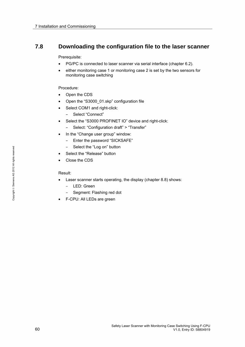
7.8 Downloading the configuration file to the laser scanner
Prerequisite:
• PG/PC is connected to laser scanner via serial interface (chapter 6.2).
• either monitoring case 1 or monitoring case 2 is set by the two sensors for monitoring case switching
Procedure:
• Open the CDS
• Open the “S3000_01.skp” configuration file
• Select COM1 and right-click:
– Select “Connect”
• Select the “S3000 PROFINET IO” device and right-click:
– Select: “Configuration draft” > “Transfer”
• In the “Change user group” window:
– Enter the password “SICKSAFE”
– Select the “Log on” button
• Select the “Release” button
• Close the CDS
Result:
• Laser scanner starts operating, the display (chapter 8.8) shows:
– LED: Green
– Segment: Flashing red dot
• F-CPU: All LEDs are green

8 Operation of the Application Example
Safety Laser Scanner with Monitoring Case Switching Using F-CPU V1.0, Entry ID: 58804919 61
Co
pyr
igh
t
Sie
me
ns
AG
20
12
All
righ
ts r
ese
rve
d
8 Operation of the Application Example Prerequisite:
• Hardware and software have been installed as described in chapter 7.
The chapter describes the following actions:
• Creating the initial state of the setup
• Operating monitoring case 1
• Setting monitoring case 2
• Operating monitoring case 2
• Error when switching the monitoring case
8.1 Creating the initial state of the setup
Set monitoring case 1:
• Switch the F-CPU to RUN
• Switch off the power supplies for F-CPU, signal modules and laser scanner (state: power off)
• Activate sensor 1 (“0” signal), deactivate sensor 2 (“1” signal)
• Switch on the power supplies for F-CPU, signal modules and laser scanner (state: power on)
Monitoring area of the laser scanner:
• No object in the monitoring area
Result:
• Indicator light is off
• Laser scanner with active monitoring case 1 (field set 1)

8 Operation of the Application Example
62 Safety Laser Scanner with Monitoring Case Switching Using F-CPU
V1.0, Entry ID: 58804919
Co
pyr
igh
t
Sie
me
ns
AG
20
12
All
righ
ts r
ese
rve
d
8.2 Operating monitoring case 1
Table 8-1
Indicator light Laser scanner No. Action Explanation
Response State Display (*1)
1 Press the acknowledge-ment pushbutton
Acknowledgement necessary after power on
--- Off No error
2 Press the start pushbutton --- Off > On On No error
3 Press the stop pushbutton --- On > Off Off No error
4 Press the start pushbutton --- Off > On On No error
5 Set object in warning field 2
Non-active monitoring case
--- On No error
6 Set object in protective field 2
Non-active monitoring case
--- On No error
7 Set object in warning field 1
Active monitoring case
--- On Warning field violated
8 Set object in protective field 1
Active monitoring case
On > Off Off Protective field violated
9 Press the start pushbutton --- --- Off Protective field violated
10 Remove object from field set 1
Restart interlock --- Off No error
11 Press the start pushbutton Restart interlock --- Off No error
12 Press the acknowledge-ment pushbutton
--- --- Off No error
13 Press the start pushbutton --- Off > On On No error
(*1): See chapter 8.8.
8.3 Setting monitoring case 2
Table 8-2
Indicator light Laser scannerNo. Action Explanation
Response State Display (*1)
14 Switch ... ... from monitoring case 1: Sensor 1 = “0” Sensor 2 = “1” ... to monitoring case 2: Sensor 1 = “1” Sensor 2 = “0”
Switching must be performed within the time parameterized in the “Monitoring_Case_Switching” block (switching time).
--- On No error
(*1): See chapter 8.8.

8 Operation of the Application Example
Safety Laser Scanner with Monitoring Case Switching Using F-CPU V1.0, Entry ID: 58804919 63
Co
pyr
igh
t
Sie
me
ns
AG
20
12
All
righ
ts r
ese
rve
d
8.4 Operating monitoring case 2
Table 8-3
Indicator light Laser scanner No. Action Explanation
Response State Display (*1)
15 Set object in warning field 1
Non-active monitoring case
--- On No error
16 Set object in protective field 1
Non-active monitoring case
--- On No error
17 Set object in warning field 2
Active monitoring case
--- On Warning field violated
18 Set object in protective field 2
Active monitoring case
On > Off Off Protective field violated
19 Press the start pushbutton --- Off Protective field violated
20 Remove object from field set 2
Restart interlock --- Off No error
21 Press the start pushbutton Restart interlock --- Off No error
22 Press the acknowledge-ment pushbutton
--- Off No error
23 Press the start pushbutton Off > On On No error
(*1): See chapter 8.8.
8.5 Error when switching the monitoring case
Indicator light Laser scanner No. Action Explanation
Response State Display (*1)
24 Sensor 1: Unchanged “1” Sensor 2: From “0” to “1”
Non-permissible switch-ing state of the sensors
On > Off Off Incorrect operation of the control inputs
25 Press the start pushbutton --- Off Incorrect operation of the control inputs
26 Press the acknowledge-ment pushbutton
--- Off Incorrect operation of the control inputs
27 Press the start pushbutton --- Off Incorrect operation of the control inputs
28 Sensor 1: Unchanged “1” Sensor 2: From “1” to “0”
--- Off Incorrect operation of the control inputs
29 Power off --- --- ---
30 Power on --- Off No error
31 Press the acknowledge-ment pushbutton
Acknowledgement nec-essary after power on
--- Off No error
(*1): See chapter 8.8.

8 Operation of the Application Example
64 Safety Laser Scanner with Monitoring Case Switching Using F-CPU
V1.0, Entry ID: 58804919
Co
pyr
igh
t
Sie
me
ns
AG
20
12
All
righ
ts r
ese
rve
d
8.6 Watch and force table
The “Watch_Table_1” table can be used to
• display if a component of the F-I/O is passivated (laser scanner, F-DI, F-DO)
• reintegrate the passivated F-DO: Positive edge at “Ack_Passivation” (Modify variable)
Open the table as follows:
• Open the Project tree
• Open “PLC_1 (CPU 315F-2 PN/DP)”
• Open “Watch and force tables”
• Open the “Watch_Table_1” table
• Select “Go online”
• Select “Monitor all”
Result:
Figure 8-1
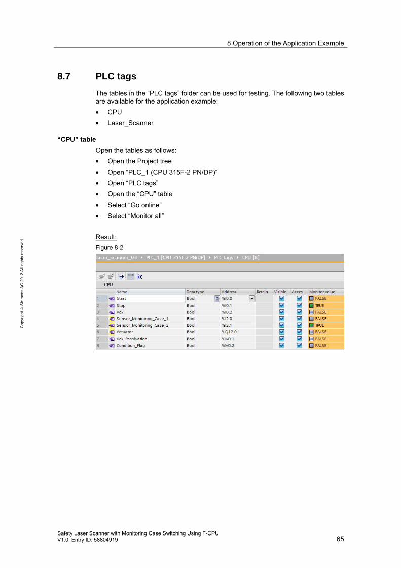
8 Operation of the Application Example
Safety Laser Scanner with Monitoring Case Switching Using F-CPU V1.0, Entry ID: 58804919 65
Co
pyr
igh
t
Sie
me
ns
AG
20
12
All
righ
ts r
ese
rve
d
8.7 PLC tags
The tables in the “PLC tags” folder can be used for testing. The following two tables are available for the application example:
• CPU
• Laser_Scanner
“CPU” table
Open the tables as follows:
• Open the Project tree
• Open “PLC_1 (CPU 315F-2 PN/DP)”
• Open “PLC tags”
• Open the “CPU” table
• Select “Go online”
• Select “Monitor all”
Result:
Figure 8-2

8 Operation of the Application Example
66 Safety Laser Scanner with Monitoring Case Switching Using F-CPU
V1.0, Entry ID: 58804919
Co
pyr
igh
t
Sie
me
ns
AG
20
12
All
righ
ts r
ese
rve
d
“Laser_Scanner” table
Open the tables as follows:
• Open the Project tree
• Open “PLC_1 (CPU 315F-2 PN/DP)”
• Open “PLC tags”
• Open the “Laser_Scanner” table
• Select “Go online”
• Select “Monitor all”
Result:
Figure 8-3

8 Operation of the Application Example
Safety Laser Scanner with Monitoring Case Switching Using F-CPU V1.0, Entry ID: 58804919 67
Co
pyr
igh
t
Sie
me
ns
AG
20
12
All
righ
ts r
ese
rve
d
8.8 Indications on the laser scanner
The display of the laser scanner shows the laser scanner states. The following ta-ble shows examples of indications on the laser scanner (/1/).
Table 8-4
Laser scanner display State
LED Segment
Explanations
No error Green: On
---
Warning field violated
Green: On Yellow: On
Object in the warning field
Protective field violated
Green: On Yellow: On
Object in the protective field
Incorrect opera-tion of the con-trol inputs
Green: On
Incorrect operation of the control inputs for switching the monitoring cases

9 Evaluation according to IEC 62061 and ISO 13849
68 Safety Laser Scanner with Monitoring Case Switching Using F-CPU
V1.0, Entry ID: 58804919
Co
pyr
igh
t
Sie
me
ns
AG
20
12
All
righ
ts r
ese
rve
d
9 Evaluation according to IEC 62061 and ISO 13849
9.1 Information on the standards
Overview
For an overview of IEC 62061, please refer to the following Safety Functional Ex-ample:
Practical Application of IEC 62061 Illustrated Using an Application Example with SIMATIC S7 Distributed Safety (/11/)
For an overview of ISO 13849-1, please refer to the following book:
Funktionale Sicherheit von Maschinen und Anlagen. Umsetzung der europäischen Maschinenrichtlinie in der Praxis (/12/).
Calculations
Support for the calculations is provided by:
Safety Evaluation Tool (SET) (/15/)
9.2 Safety function
The following considerations are based on the following safety function (example):
“When the active protective field is violated, the machine must be stopped.”
The application example does not consider the entire safety function:
Table 9-1
Tasks of a safety function
Detect Evaluate React
Is considered Is considered Is not considered
In the following, the above-listed tasks of a safety function are evaluated according to the two standards EN 62061 and EN ISO 13849-1.
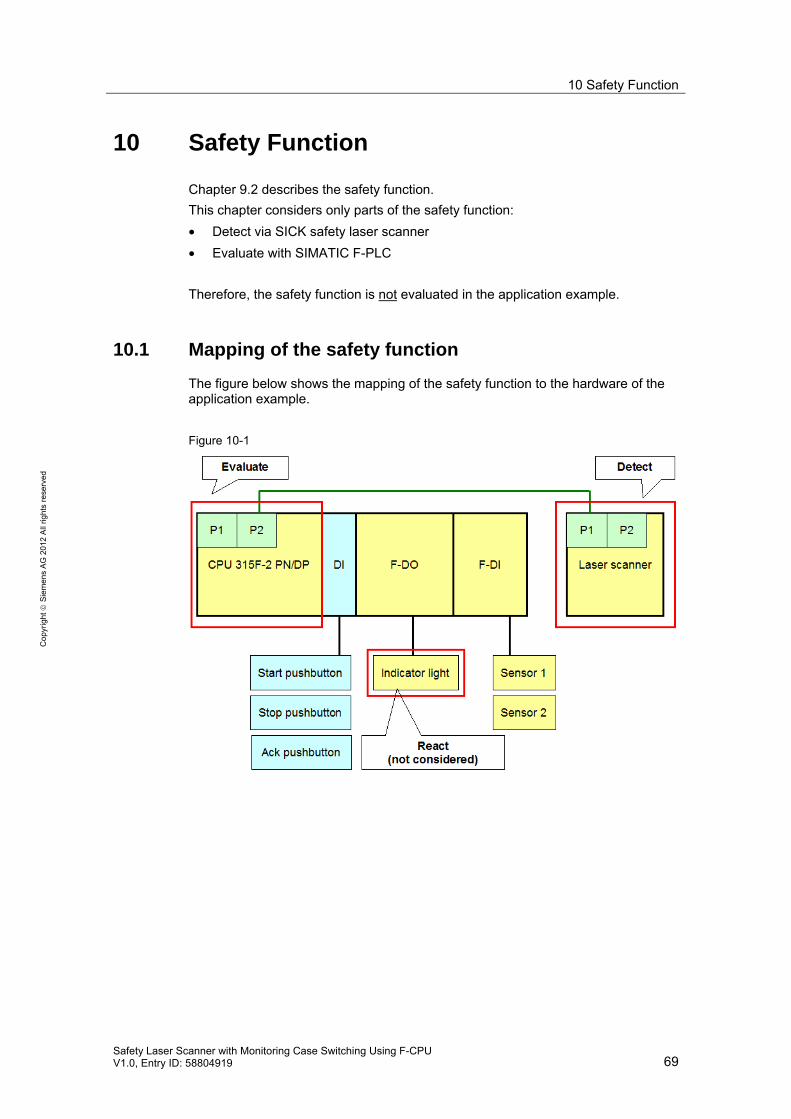
10 Safety Function
Safety Laser Scanner with Monitoring Case Switching Using F-CPU V1.0, Entry ID: 58804919 69
Co
pyr
igh
t
Sie
me
ns
AG
20
12
All
righ
ts r
ese
rve
d
10 Safety Function
Chapter 9.2 describes the safety function.
This chapter considers only parts of the safety function:
• Detect via SICK safety laser scanner
• Evaluate with SIMATIC F-PLC
Therefore, the safety function is not evaluated in the application example.
10.1 Mapping of the safety function
The figure below shows the mapping of the safety function to the hardware of the application example.
Figure 10-1

10 Safety Function
70 Safety Laser Scanner with Monitoring Case Switching Using F-CPU
V1.0, Entry ID: 58804919
Co
pyr
igh
t
Sie
me
ns
AG
20
12
All
righ
ts r
ese
rve
d
10.2 Assessment of Detect
Component involved:
SICK safety laser scanner
10.2.1 Evaluation according to IEC 62061
Result:
Table 10-1
Result Reason
SILCL 2
PFHD 76.7 * 10-9
Specified by the manufacturer, SICK AG
10.2.2 Evaluation according to ISO 13849-1
Result:
Table 10-2
Result Reason
PL d
Average probability of a dangerous failure per hour
76.7 * 10-9
Specified by the manufacturer, SICK AG
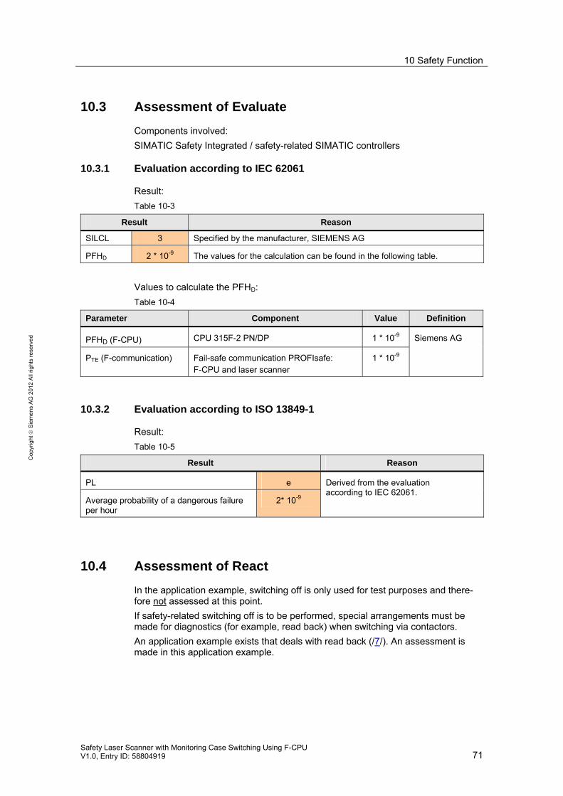
10 Safety Function
Safety Laser Scanner with Monitoring Case Switching Using F-CPU V1.0, Entry ID: 58804919 71
Co
pyr
igh
t
Sie
me
ns
AG
20
12
All
righ
ts r
ese
rve
d
10.3 Assessment of Evaluate
Components involved:
SIMATIC Safety Integrated / safety-related SIMATIC controllers
10.3.1 Evaluation according to IEC 62061
Result:
Table 10-3
Result Reason
SILCL 3 Specified by the manufacturer, SIEMENS AG
PFHD 2 * 10-9 The values for the calculation can be found in the following table.
Values to calculate the PFHD:
Table 10-4
Parameter Component Value Definition
PFHD (F-CPU) CPU 315F-2 PN/DP 1 * 10-9
PTE (F-communication) Fail-safe communication PROFIsafe: F-CPU and laser scanner
1 * 10-9
Siemens AG
10.3.2 Evaluation according to ISO 13849-1
Result:
Table 10-5
Result Reason
PL e
Average probability of a dangerous failure per hour
2* 10-9
Derived from the evaluation according to IEC 62061.
10.4 Assessment of React
In the application example, switching off is only used for test purposes and there-fore not assessed at this point.
If safety-related switching off is to be performed, special arrangements must be made for diagnostics (for example, read back) when switching via contactors.
An application example exists that deals with read back (/7/). An assessment is made in this application example.

11 Glossary
72 Safety Laser Scanner with Monitoring Case Switching Using F-CPU
V1.0, Entry ID: 58804919
Co
pyr
igh
t
Sie
me
ns
AG
20
12
All
righ
ts r
ese
rve
d
11 Glossary
Table 11-1
Abbreviation / term in the document
Meaning
“1” signal Signal has the TRUE logic state
CDS Tool to configure and diagnose the SICK S3000 safety laser scanner: Con-figuration & Diagnostic Software
ESPE Electro-sensitive protective equipment
Field set x Field set x consists of protective field x and warning field x. Field set x can be allocated to monitoring case y.
MMC SIMATIC Micro Memory Card
OSSD Output signal switching device: Signal output of the protective device that is used to stop the dangerous movement.
PG/PC Programming device / personal computer
Power off The power supply for F-CPU, signal modules and laser scanner is switched off.
Power on The power supply for F-CPU, signal modules and laser scanner is switched on.
PROFIsafe address Each fail-safe component has its own PROFIsafe address. Safety mode requires that the PROFIsafe address be configured in the hard-ware configuration and set on the component. Depending on the component, this is done via the DIP switch or configuration.
User program User program = safety program + standard user program The term “safety program” refers to the fail-safe part of the user program and is used instead of “fail-safe user program”, “F-program”, etc. For differentia-tion purposes, the non-safety-related part of the user program is referred to as the “standard user program”.

12 References
Safety Laser Scanner with Monitoring Case Switching Using F-CPU V1.0, Entry ID: 58804919 73
Co
pyr
igh
t
Sie
me
ns
AG
20
12
All
righ
ts r
ese
rve
d
12 References Notes with reference (/x/) in the document:
Table 12-1
Topic Link / source
SICK S3000 Safety Laser Scanner Operating Instructions
www.sick.com /1/
SICK S3000 PROFINET IO and S3000 PROFINET IO-OF Safety Laser Scanner Addendum Operating Instructions
/2/ Reference to the document http://support.automation.siemens.com/WW/view/en/58804919
/3/ SIMATIC S7-300, CPU 31xC and CPU 31x: Installation / Operating Instructions
http://support.automation.siemens.com/WW/view/en/13008499
/4/ PROFINET / System Manual http://support.automation.siemens.com/WW/view/en/19292127
/7/ Integration of the Readback Signal in an Application of Category 4 according to EN 954-1: 1996 (with evaluation according to EN 62061 and EN ISO 13849-1: 2006)
http://support.automation.siemens.com/WW/view/en/21331098
/8/ SICK / Help on configuration S3000/S300/S200 Configuration & Diagnostic Software
CD-ROM for CDS
/9/ SIMATIC Industrial Software SIMATIC Safety – Configuring and Programming
http://support.automation.siemens.com/WW/view/en/54110126
/11/ Practical Application of IEC 62061 Illustrated Using an Application Example with SIMATIC S7 Distributed Safety
http://support.automation.siemens.com/WW/view/en/23996473
/12/ Funktionale Sicherheit von Maschinen und Anlagen. Umsetzung der europäischen Ma-schinenrichtlinie in der Praxis.
ISBN-13: 978-3-89578-281-7, ISBN-10: 3-89578-281-5
/15/ Safety Evaluation Tool http://www.industry.siemens.com/topics/global/en/safety-integrated/machine-safety/safety-evaluation-tool/Pages/Default.aspx
/16/ SIMATIC / Automation System S7-300 ET 200M Distributed I/O Device Fail-safe signal modules Installation and Operating Manual
http://support.automation.siemens.com/WW/view/en/19026151
/18/ System Description: Safety Engineering in SIMATIC S7
http://support.automation.siemens.com/WW/view/en/12490443
/20/ PROFINET with STEP 7 V11 Function Manual
http://support.automation.siemens.com/WW/view/en/49948856
/21/ SIMATIC Safety Getting Started
http://support.automation.siemens.com/WW/view/en/49972838
/22/ STEP 7 Professional V11.0 SP2 http://support.automation.siemens.com/WW/view/en/57185407
Notes without reference (/x/) in the document:
Table 12-2
Topic Link / source
Siemens Industry Online Support http://support.automation.siemens.com

13 History
74 Safety Laser Scanner with Monitoring Case Switching Using F-CPU
V1.0, Entry ID: 58804919
Co
pyr
igh
t
Sie
me
ns
AG
20
12
All
righ
ts r
ese
rve
d
13 History
Version Date Modification
V1.0 03/2012 First edition