Applications of Petri Nets to Human-in-the-Loop Control for
30
167 7 Applications of Petri Nets to Human-in-the-Loop Control for Discrete Automation Systems Jin-Shyan Lee and Pau-Lo Hsu 1. Introduction For discrete automation systems, certain human operations may violate de- sired safety requirements and result in catastrophic failure. For such human- in-the-loop systems, this paper proposes a systematic approach to developing supervisory agents which guarantee that manual operations meet required safety specifications. In the present approach, Petri nets (PN) are applied to construct a system model and synthesize a desired supervisor. Applications to 1) a rapid thermal process (RTP) in semiconductor manufacturing controlled over the Internet (Lee and Hsu, 2003) and 2) a two-robot remote surveillance system (Lee et al., 2005) are provided to demonstrate the practicability of the developed supervisory control approach. The technique developed in this pa- per is significant in industrial applications. 1.1 General Review Basically, an automated process is inherently a discrete event system (DES). The Petri net (PN) has been developed as a powerful tool for modelling, analy- sis, simulation, and control of DES. PN was named after Carl A. Petri (1962), who created a net-like mathematical tool for describing relations between the conditions and the events. PN was further developed to meet the need in specifying process synchronization, asynchronous events, concurrent opera- tions, and conflicts or resource sharing for a variety of industrial automated systems at the discrete-event level. Starting in the late of 1970’s, researchers in- vestigated possible industrial applications of PN in discrete-event systems as in the survey/tutorial papers of Murata (1989), Zurawski and Zhou (1994), David and Alla (1994), and Zhou and Jeng (1998). Recently, due to the rapid development of Internet technology, system moni- toring and control no longer needs to be conducted within a local area. Several Source: Manufacturing the Future, Concepts - Technologies - Visions , ISBN 3-86611-198-3, pp. 908, ARS/plV, Germany, July 2006, Edited by: Kordic, V.; Lazinica, A. & Merdan, M. Open Access Database www.i-techonline.com
Transcript of Applications of Petri Nets to Human-in-the-Loop Control for

167
7
Applications of Petri Nets to Human-in-the-Loop
Control for Discrete Automation Systems
Jin-Shyan Lee and Pau-Lo Hsu
1. Introduction
For discrete automation systems, certain human operations may violate de-
sired safety requirements and result in catastrophic failure. For such human-
in-the-loop systems, this paper proposes a systematic approach to developing
supervisory agents which guarantee that manual operations meet required
safety specifications. In the present approach, Petri nets (PN) are applied to
construct a system model and synthesize a desired supervisor. Applications to
1) a rapid thermal process (RTP) in semiconductor manufacturing controlled
over the Internet (Lee and Hsu, 2003) and 2) a two-robot remote surveillance
system (Lee et al., 2005) are provided to demonstrate the practicability of the
developed supervisory control approach. The technique developed in this pa-
per is significant in industrial applications.
1.1 General Review
Basically, an automated process is inherently a discrete event system (DES).
The Petri net (PN) has been developed as a powerful tool for modelling, analy-
sis, simulation, and control of DES. PN was named after Carl A. Petri (1962),
who created a net-like mathematical tool for describing relations between the
conditions and the events. PN was further developed to meet the need in
specifying process synchronization, asynchronous events, concurrent opera-
tions, and conflicts or resource sharing for a variety of industrial automated
systems at the discrete-event level. Starting in the late of 1970’s, researchers in-
vestigated possible industrial applications of PN in discrete-event systems as
in the survey/tutorial papers of Murata (1989), Zurawski and Zhou (1994),
David and Alla (1994), and Zhou and Jeng (1998).
Recently, due to the rapid development of Internet technology, system moni-
toring and control no longer needs to be conducted within a local area. Several
Source: Manufacturing the Future, Concepts - Technologies - Visions , ISBN 3-86611-198-3, pp. 908, ARS/plV, Germany, July 2006, Edited by: Kordic, V.; Lazinica, A. & Merdan, M.
Ope
n A
cces
s D
atab
ase
ww
w.i-
tech
onlin
e.co
m

Manufacturing the Future: Concepts, Technologies & Visions 168
remote approaches have been proposed which allow people to monitor the
automated processes from great distances (Weaver et al., 1999; Yang et al.,
2002; Kress et al., 2001; Lee and Hsu, 2004; Huang and Mak, 2001).
Practically, to perform maintenance functions in hazardous environments
without their exposure to dangers is a unique application of the remote tech-
nology. By conducting remote access using IP-based networks, an entire Inter-
net-based control system is inherently a DES and its state change is driven by
occurrences of individual events. The supervisory control theory provides a
suitable framework for analyzing DES (Ramadge and Wonham, 1987, 1989;
Balemi et al., 1993) and most existing methods are based on automata models.
The calculus of communicating systems (CCS), which was invented by Robin
Milner (1989), is another classical formalism for representing systems of con-
current processes. However, these available methods often involve exhaustive
searches of overall system behaviours and result in state-space explosion de-
sign as system becomes more complex. On the other hand, PN is an efficient
approach to model the DES and its models are normally more compact than
the automata models. Also, PN is better suitable for modelling systems with
parallel and concurrent activities. In addition, PN has an appealing graphical
representation with a powerful algebraic formulation for supervisory control
design (Giua and DiCesare, 1991; Moody and Antsaklis, 1998; Uzam et al.,
2000).
1.2 Problem Statement
Typically, an Internet-based control system (remote access using IP-based
networks) is a “human-in-the-loop” system since people use a general web
browser or specific software to monitor and control remotely located systems.
As shown in Figure 1 (a), the human operator is involved in the loop and
sends control commands according to the observed status displayed by the
state and/or image feedback. Research results indicate that approximately 80%
of industrial accidents are attributed to human errors, such as omitting a step,
falling asleep and improper control of the system (Rasmussen et al., 1994).
However, the Internet-based control literature provides few solutions for re-
ducing or eliminating the possibility of human errors. Therefore, solutions to
reduce or eliminate the possibility of human errors are required in the Inter-
net-based control systems.
Applications of Petri Nets to Human-in-the-Loop Control for Discrete… 169
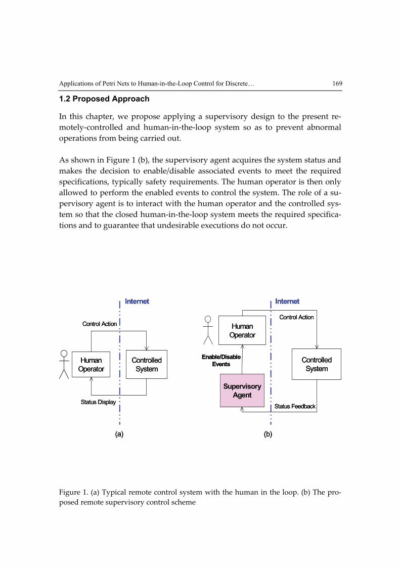
1.2 Proposed Approach
In this chapter, we propose applying a supervisory design to the present re-
motely-controlled and human-in-the-loop system so as to prevent abnormal
operations from being carried out.
As shown in Figure 1 (b), the supervisory agent acquires the system status and
makes the decision to enable/disable associated events to meet the required
specifications, typically safety requirements. The human operator is then only
allowed to perform the enabled events to control the system. The role of a su-
pervisory agent is to interact with the human operator and the controlled sys-
tem so that the closed human-in-the-loop system meets the required specifica-
tions and to guarantee that undesirable executions do not occur.
Controlled
System
Supervisory
Agent
Human
Operator
Enable/Disable
Events
Status Feedback
Control Action
Internet
Controlled
System
Human
Operator
Control Action
Status Display
Internet
(a) (b)
Controlled
System
Supervisory
Agent
Human
Operator
Enable/Disable
Events
Status Feedback
Control Action
Internet
Controlled
System
Human
Operator
Control Action
Status Display
Internet
(a) (b)
Figure 1. (a) Typical remote control system with the human in the loop. (b) The pro-
posed remote supervisory control scheme

Manufacturing the Future: Concepts, Technologies & Visions 170
2. PN-Based Modelling
2.1 Basic PN Concepts
A PN is identified as a particular kind of bipartite directed graph populated by
three types of objects. They are places, transitions, and directed arcs connect-
ing places and transitions. Formally, a PN can be defined as
),,,( OITPG = (1)
where,
},...,,{ 21 mpppP = is a finite set of places, where 0>m ;
},...,,{ 21 ntttT = is a finite set of transitions with ∅≠∪TP and ∅=∩TP ,
where 0>n ;
NTPI →×: is an input function that defines a set of directed arcs from P to
T, where N = {0, 1, 2, …};
NPTO →×: is an output function that defines a set of directed arcs from T
to P.
A marked PN is denoted as (G, M0), where M0: P → N is the initial marking. A
transition t is enabled if each input place p of t contains at least the number of
tokens equal to the weight of the directed arc connecting p to t. When an en-
abled transition fires, it removes the tokens from its input places and deposits
them on its output places. PN models are suitable to represent the systems that
exhibit concurrency, conflict, and synchronization.
Some important PN properties in manufacturing systems include bounded-
ness (no capacity overflow), liveness (freedom from deadlock), conservative-
ness (conservation of non-consumable resources), and reversibility (cyclic be-
havior). The concept of liveness is closely related to the complete absence of
deadlocks. A PN is said to be live if, no matter what marking has been reached
from the initial marking, it is possible to ultimately fire any transition of the
net by progressing through some further firing sequences. This means that a
live PN guarantees deadlock-free operation, no matter what firing sequence is
chosen. Validation methods of these properties include reachability analysis,
invariant analysis, reduction method, siphons/traps-based approach, and
simulation (Zhou and Jeng, 1998).

Applications of Petri Nets to Human-in-the-Loop Control for Discrete… 171
2.2 Elementary PN Models
At the modelling stage, one needs to focus on the major operations and their
sequential or precedent, concurrent, or conflicting relationships. The basic rela-
tions among these processes or operations can be classified as follows.
1. Sequential: As shown in Figure 2 (a), if one operation follows the other,
then the places and transitions representing them should form a cascade
or sequential relation in PNs.
2. Concurrent: If two or more operations are initiated by an event, they form a
parallel structure starting with a transition, i.e., two or more places are the
outputs of a same transition. An example is shown in Figure 2 (b). The
pipeline concurrent operations can be represented with a sequentially-
connected series of places/transitions in which multiple places can be
marked simultaneously or multiple transitions are enabled at certain mar-
kings.
3. Cyclic: As shown in Figure 2 (c), if a sequence of operations follow one af-
ter another and the completion of the last one initiates the first one, then a
cyclic structure is formed among these operations.
4. Conflicting: As shown in Figure 2 (d), if either of two or more operations
can follow an operation, then two or more transitions form the outputs
from the same place.
5. Mutually Exclusive: As shown in Figure 2 (e), two processes are mutually
exclusive if they cannot be performed at the same time due to constraints
on the usage of shared resources. A structure to realize this is through a
common place marked with one token plus multiple output and input arcs
to activate these processes.
In this chapter, PN models of the human behaviours will be constructed based
on these elementary models.
2.3 System Modeling
The human behaviors can be modeled using the command/response concept.
As shown in Figure 3, each human operation is modeled as a task with a start
transition, end transition, progressive place and completed place. Transitions
drawn with dark symbols are events that are controllable by the remote-
located human through the network. Note that the start transition is a control-
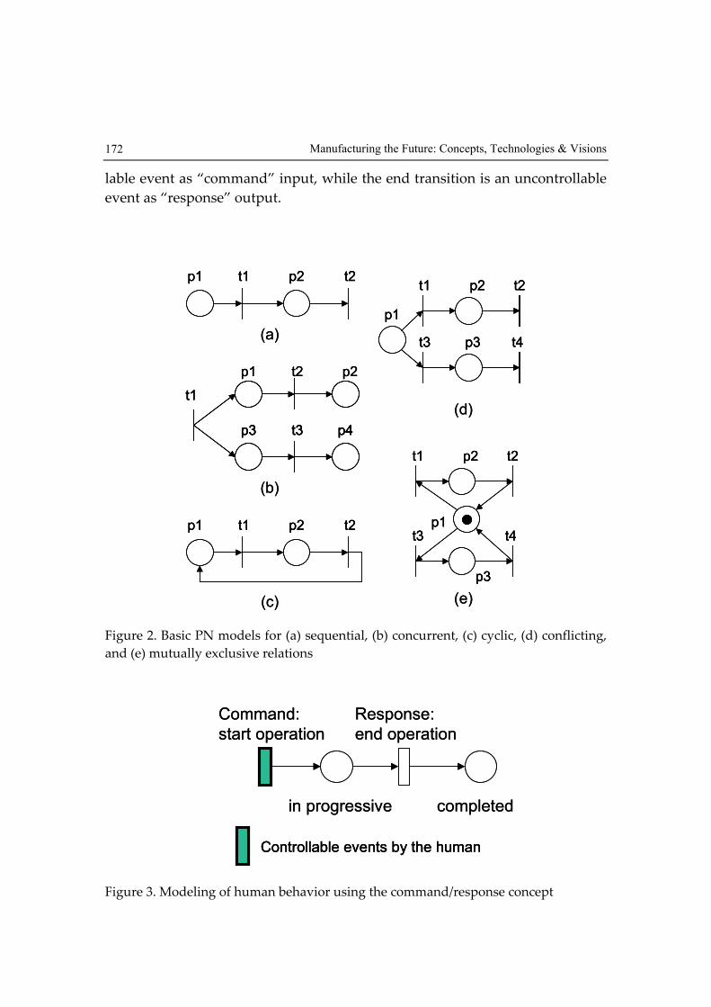
Manufacturing the Future: Concepts, Technologies & Visions 172
lable event as “command” input, while the end transition is an uncontrollable
event as “response” output.
p2t1p1 t2
(a)
p1 t2 p2
t1
t3p3 p4
(b)
t2
p1
t3
t1 p2
t4p3
(d)
p2t1p1 t2
(c)
t2
t3
t1 p2
t4
p3
p1
(e)
p2t1p1 t2p2t1p1 t2
(a)
p1 t2 p2
t1
t3p3 p4
p1 t2 p2
t1
t3p3 p4
t1
t3p3 p4
(b)
t2
p1
t3
t1 p2
t4p3
t2
p1
t3
t1 p2
t4p3
(d)
p2t1p1 t2p2t1p1 t2
(c)
t2
t3
t1 p2
t4
p3
p1
t2
t3
t1 p2
t4
p3
p1
(e)
Figure 2. Basic PN models for (a) sequential, (b) concurrent, (c) cyclic, (d) conflicting,
and (e) mutually exclusive relations
completedin progressive
Command:
start operation
Response:
end operation
Controllable events by the human
completedin progressive
Command:
start operation
Response:
end operation
Controllable events by the humanControllable events by the human
Figure 3. Modeling of human behavior using the command/response concept
Applications of Petri Nets to Human-in-the-Loop Control for Discrete… 173
3. PN-Based Supervisor Synthesis
3.1 Control Modes
For remote control via the Internet, we are interested in the following two con-
trol modes:
1. Automatic mode: When the system is in automatic control mode, the auto-
matic controller autonomously controls the manufacturing process with-
out user intervention (the human operator only needs to push a button to
start the control cycle). Generally, an active sequence controller is used to
automatically complete several operations in a certain order.
2. Manual mode: A system often must be open to manual control for various
purposes, such as for test runs and fault diagnosis. Here, we examine the
case in which the user can directly perform each operation. To ensure that
safety constraints are not violated, the supervisory agent is on-line exe-
cuted to acquire the system status and decide to either enable or disable
specific operations.
3.2 Specification Types
The objective of the supervisor is to restrict the behavior of the system so that
it is contained within the set of admissible states, called the specification. Two
types of specifications are classified as follows:
1. Explicit specifications for control sequences: Generally, these specifications are
“recipe-dependent”. They are enforced by a sequence controller in auto-
matic mode or by a human operator in manual mode so as to accomplish
certain tasks in a desired logical order.
2. Implicit specifications for safety requirements: These specifications are “recipe-
independent” and thus must always be obeyed throughout the whole op-
eration of the system. Basically, these specifications are required to satisfy
safety and liveness constraints. The safety specification prevents the sys-
tem from performing undesirable actions, while the liveness specification
ensures that a given behavior is repeatable. In automatic mode, these
specifications can be effectively dealt with by the sequence controller. In
manual mode, the supervisor enforces these specifications by restricting
the commands available to human operators.
Manufacturing the Future: Concepts, Technologies & Visions 174
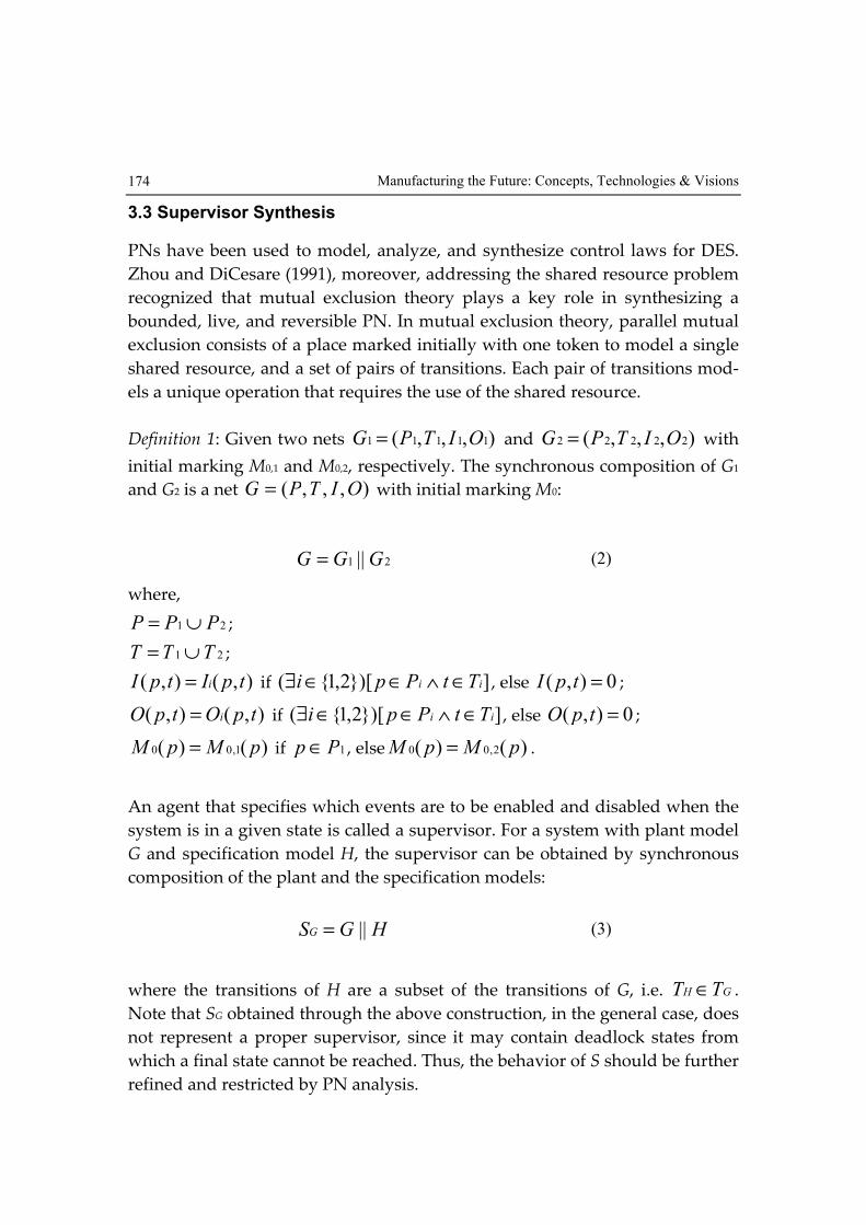
3.3 Supervisor Synthesis
PNs have been used to model, analyze, and synthesize control laws for DES.
Zhou and DiCesare (1991), moreover, addressing the shared resource problem
recognized that mutual exclusion theory plays a key role in synthesizing a
bounded, live, and reversible PN. In mutual exclusion theory, parallel mutual
exclusion consists of a place marked initially with one token to model a single
shared resource, and a set of pairs of transitions. Each pair of transitions mod-
els a unique operation that requires the use of the shared resource.
Definition 1: Given two nets ),,,( 11111 OITPG = and ),,,( 22222 OITPG = with
initial marking M0,1 and M0,2, respectively. The synchronous composition of G1
and G2 is a net ),,,( OITPG = with initial marking M0:
21 ||GGG = (2)
where,
21 PPP ∪= ;
21 TTT ∪= ;
),(),( tpItpI i= if ]})[2,1{( ii TtPpi ∈∧∈∈∃ , else 0),( =tpI ;
),(),( tpOtpO i= if ]})[2,1{( ii TtPpi ∈∧∈∈∃ , else 0),( =tpO ;
)()( 1,00 pMpM = if 1Pp∈ , else )()( 2,00 pMpM = .
An agent that specifies which events are to be enabled and disabled when the
system is in a given state is called a supervisor. For a system with plant model
G and specification model H, the supervisor can be obtained by synchronous
composition of the plant and the specification models:
HGSG ||= (3)
where the transitions of H are a subset of the transitions of G, i.e. GH TT ∈ .
Note that SG obtained through the above construction, in the general case, does
not represent a proper supervisor, since it may contain deadlock states from
which a final state cannot be reached. Thus, the behavior of S should be further
refined and restricted by PN analysis.

Applications of Petri Nets to Human-in-the-Loop Control for Discrete… 175
In this chapter, we adopt mutual exclusion concept to build the PN specifica-
tion model and then compose it with the plant model to design the supervisor.
The supervisor design procedure consists of the following steps:
Step 1) Construct the PN model of the human behaviors for system plants.
Step 2) Construct the PN model of specifications using the mutual exclusion
concept for shared resources.
Step 3) Compose the behavior and specification models to synthesize the
preliminary supervisor model.
Step 4) Analyze and verify the properties of the composed model.
Step 5) Refine the model to obtain a deadlock-free, bounded, and reversible
model.
4. Agent-based Implementation
4.1 Agent Technology
The agent technology is a new and important technique in recent novel re-
searches of the artificial intelligence. Using agent technology leads to a number
of advantages such as scalability, event-driven actions, task-orientation, and
adaptivity (Bradshaw, 1997). The concept of an agent as a computing entity is
very dependent on the application domain in which it operates. As a result,
there exists many definitions and theories on what actually constitutes an
agent and the sufficient and necessary conditions for agency. Wooldridge and
Jennings (1995) depicts an agent as a computer system that is situated in some
environment, and that is capable of autonomous actions in this environment in
order to meet its design objectives. From a software technology point of view,
agents are similar to software objects, which however run upon call by other
higher-level objects in a hierarchical structure. On the contrary, in the narrow
sense, agents must run continuously and autonomously. In addition, the dis-
tributed multiagent coordination system is defined as the agents that share the
desired tasks in a cooperative point of view, and they are autonomously exe-
cuting at different sites. For our purposes, we have adopted the description of
an agent as a software program associated to the specific function of remote
supervision for the manufacturing system. A supervisory agent is imple-
mented to acquire the system status and then enable and disable associated
tasks so as to advise and guide the manager in issuing commands.

Manufacturing the Future: Concepts, Technologies & Visions 176
4.2 Client/Server Architecture
Figure 4 shows the client/server architecture for implementing the remote su-
pervisory control system. On the remote client, the human operator uses a
Java-capable web browser, such as Netscape Navigator or Microsoft Internet
Explorer, to connect to the web server through the Internet. On the web server
side, a Java servlet handles user authentication, while a Java applet is provides
a graphical human/machine interface (HMI) and invokes the supervisory
agent. In this chapter, we use Java technology to implement the supervisory
agent on an industrial PLC, with a built-in Java-capable web server assigned to
handle the client requests.
Remote Client
(with Java-capable Web browser)
Internet
I/O Bus
� Java Servlet:
for user authentication
� Java Applet:
for graphical HMI and to
invoke supervisory agent
� Ladder Logic Diagram:
for direct sense and control
of I/O devices
Industrial PLC(with built-in Java-capable Web server)
Controlled
System
Figure 4. Implementation architecture of the supervisory control system
4.3 Interactive Modeling
A sequence diagram of the UML (Booch et al., 1999) is applied to model cli-
ent/server interaction in the remote control system. Within a sequence dia-
gram, an object is shown as a box at the top of a vertical dashed line, called the
object’s lifeline and representing the life of the object during the interaction.
Messages are represented by horizontal arrows and are drawn chronologically
from the top of the diagram to the bottom.
Figure 5 shows the sequence diagram of the implemented remote supervisory
control system. At the first stage, the Remote Client sends a hypertext transfer
protocol (HTTP) request to the Web Server. Next, the Web Server sends an HTTP
response with an authentication web page, on which the Remote Client can

Applications of Petri Nets to Human-in-the-Loop Control for Discrete… 177
login to the system by sending a request with user/password. The Web Server
then invokes a Java servlet to authenticate the user. If the authentication fails,
the Java servlet will respond with the authentication web page again. On the
other hand, if the authentication succeeds, the response of the Java servlet will
be a control web page with a Java applet. The Java applet first builds a graphi-
cal HMI and constructs a socket on the specified port to maintain continuous
communication with the server. Then, the Java applet acquires the system
status through the constructed socket and displays it on the control web page
iteratively by invoking the Device Handler to fetch the sensor states of Device
objects. Finally, the supervisory agent called by the Java applet determines en-
able/disable control buttons on the HMI according to the current system status
so as to meet the required specifications. Thus, the Remote Client can send an
action command by pushing an enabled button to control the remote system
through the constructed socket.
HTTP request
Remote
Client
Time
HTTP response (authentication page)
[Fail] HTTP response (authentication page)
HTTP request (Login request)
Check user by
Java Servlet
[Success] HTTP response (control page)
1. Build graphic HMI by Java Applet.
2. Build socket-communication.
3. Acquire and display system status via
socket iteratively.
4. Run supervisory agent (enable/disable
control buttons).
Request via socket (action command)
Device
Handler
getSensor*getSensor
returnreturn(data)
Iteration
setActuatorsetActuator
Device
(sensor/
actuator)
Web
Server
HTTP request
Remote
Client
Time
HTTP response (authentication page)
[Fail] HTTP response (authentication page)
HTTP request (Login request)
Check user by
Java Servlet
[Success] HTTP response (control page)
1. Build graphic HMI by Java Applet.
2. Build socket-communication.
3. Acquire and display system status via
socket iteratively.
4. Run supervisory agent (enable/disable
control buttons).
Request via socket (action command)
Device
Handler
getSensor*getSensor
returnreturn(data)return(data)
Iteration
setActuatorsetActuator
Device
(sensor/
actuator)
Web
Server
Figure 5. Interactive modeling with sequence diagram
Manufacturing the Future: Concepts, Technologies & Visions 178
5. Application 1: A Rapid Thermal Process
5.1 System Description
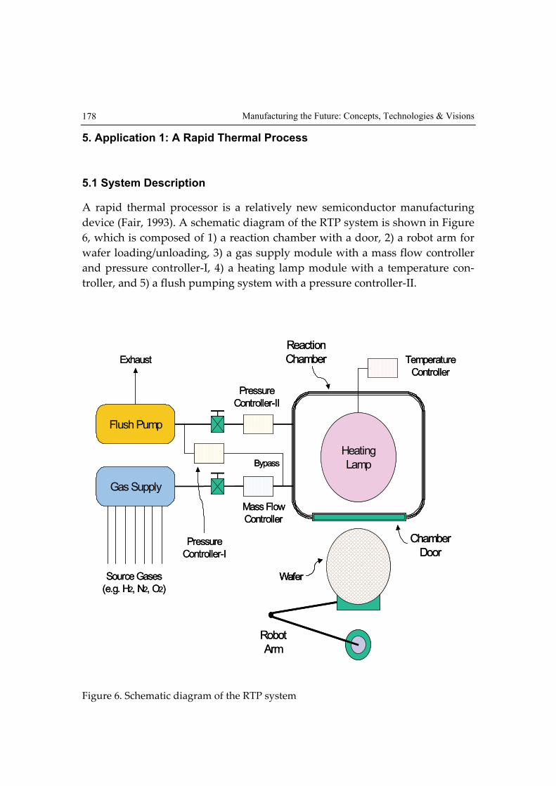
A rapid thermal processor is a relatively new semiconductor manufacturing
device (Fair, 1993). A schematic diagram of the RTP system is shown in Figure
6, which is composed of 1) a reaction chamber with a door, 2) a robot arm for
wafer loading/unloading, 3) a gas supply module with a mass flow controller
and pressure controller-I, 4) a heating lamp module with a temperature con-
troller, and 5) a flush pumping system with a pressure controller-II.
Temperature
Controller
Heating
Lamp
Flush Pump
Gas Supply
Pressure
Controller-I
Pressure
Controller-II
Mass Flow
Controller
Chamber
Door
Robot
Arm
Wafer
Exhaust
Source Gases
(e.g. H2, N2, O2)
Bypass
Reaction
Chamber Temperature
Controller
Heating
Lamp
Flush Pump
Gas Supply
Pressure
Controller-I
Pressure
Controller-II
Mass Flow
Controller
Chamber
Door
Robot
Arm
WaferWafer
Exhaust
Source Gases
(e.g. H2, N2, O2)
Bypass
Reaction
Chamber
Figure 6. Schematic diagram of the RTP system

Applications of Petri Nets to Human-in-the-Loop Control for Discrete… 179
A realistic “recipe” of the hydrogen baking process, i.e. the explicit specifica-
tion as mentioned in Section 3.2, is as follows:
Step 6) Load the raw wafer.
Step 7) Close the chamber door.
Step 8) Open the gas valve to supply gases with a desired gas flow rate and
pressure of 2.8 liters per minute (lpm) and 0.5 Torr, respectively.
Step 9) Close the gas valve.
Step 10) Turn on the heating lamp to bake the wafer with a desired baking
temperature and duration of 1000 C° and 4 seconds, respectively.
Step 11) Turn off the heating lamp to cool down the chamber to a desired
temperature of less than 20 C° .
Step 12) Turn on the flush pump with a desired pressure of less than 0.05
Torr.
Step 13) Turn off the flush pump.
Step 14) Open the chamber door.
Step 15) Unload the processed wafer.
The initial state of the components in the RTP is either closed or off, except that
the door is open. The following safety specifications, i.e. the implicit specifica-
tion mentioned in Section 3.2, must be enforced throughout system operation.
Spec-1: Wafer Loading is allowed only when no wafer is in the chamber.
Spec-2: Wafer Loading/unloading is allowed only when the door is open.
Spec-3: The gas valve must be closed when the flush pump is applied to the
chamber.
Spec-4: The gas valve, heating lamp, and flush pump cannot be started when
the door is open.
Manufacturing the Future: Concepts, Technologies & Visions 180
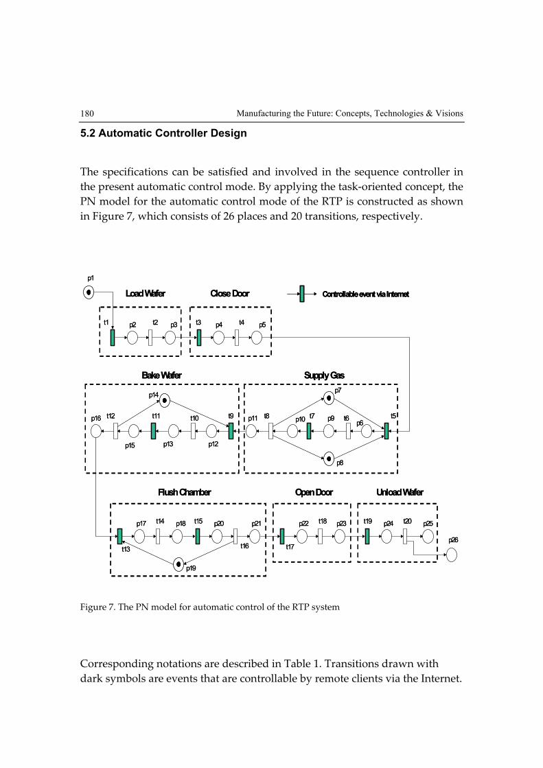
5.2 Automatic Controller Design
The specifications can be satisfied and involved in the sequence controller in
the present automatic control mode. By applying the task-oriented concept, the
PN model for the automatic control mode of the RTP is constructed as shown
in Figure 7, which consists of 26 places and 20 transitions, respectively.
p2 p3t2t1 p4 p5t4t3
p1
p6p9 t6 t5
p12p13
t10 t9 p10p11 t8 t7
p15
p16 t12 t11
p14
p8
p7
Load Wafer Close Door
Supply GasBake Wafer
p20 p21
t16
t15p17 p18t14
t13
p24 p25t20t19p22 p23t18
t17
Unload WaferOpen DoorFlush Chamber
p26
p19
Controllable event via Internet
p2 p3t2t1 p4 p5t4t3
p1
p6p9 t6 t5
p12p13
t10 t9 p10p11 t8 t7
p15
p16 t12 t11
p14
p8
p7
Load Wafer Close Door
Supply GasBake Wafer
p20 p21
t16
t15p17 p18t14
t13
p24 p25t20t19p22 p23t18
t17
Unload WaferOpen DoorFlush Chamber
p26
p19
Controllable event via InternetControllable event via Internet
Figure 7. The PN model for automatic control of the RTP system
Corresponding notations are described in Table 1. Transitions drawn with
dark symbols are events that are controllable by remote clients via the Internet.

Applications of Petri Nets to Human-in-the-Loop Control for Discrete… 181
Place Description Transition Description
p1 Raw wafer buffer t1 Cmd: start loading wafer
p2 Loading wafer t2 Re: end loading wafer
p3 Loading wafer completed t3 Cmd: start closing chamber door
p4 Closing chamber door t4 Re: end closing chamber door
p5 Closing chamber door completed t5 Cmd: start opening gas valve
p6 Opening gas valve t6 Re: end opening gas valve
p7 Mass flow controller ready t7 Cmd: start closing gas valve
p8 Pressure controller-I ready t8 Re: end closing gas valve
p9 Opening gas valve completed t9 Cmd: start turning on heating lamp
p10 Closing gas valve t10 Re: end turning on heating lamp
p11 Closing gas valve completed t11 Cmd: start turning off heating lamp
p12 Turning on heating lamp t12 Re: end turning off heating lamp
p13 Turning on heating lamp completed t13 Cmd: start turning on flush pump
p14 Temperature controller ready t14 Re: end turning on flush pump
p15 Turning off heating lamp t15 Cmd: start turning off flush pump
p16 Turning off heating lamp completed t16 Re: end turning off flush pump
p17 Turning on flush pump t17 Cmd: start opening chamber door
p18 Turning on flush pump completed t18 Re: end opening chamber door
p19 Pressure controller-II ready t19 Cmd: start unloading wafer
p20 Turning off flush pump t20 Re: end unloading wafer
p21 Turning off flush pump completed
p22 Opening chamber door
p23 Opening chamber door completed
p24 Unloading wafer
p25 Unloading wafer completed
p26 Processed wafer buffer
Table 1. Notations for the PN of the RTP system in Figure 7
5.3 Supervisor Synthesis
For manual control mode, the plant model is formed by unconnecting each
pair of transitions for the tasks in Figure 7. In the specification model, Spec-1
and Spec-2 are modeled as the pre-conditions of the associated operations,
while Spec-3 and Spec-4 are built by using the mutual exclusion concept. The
Manufacturing the Future: Concepts, Technologies & Visions 182
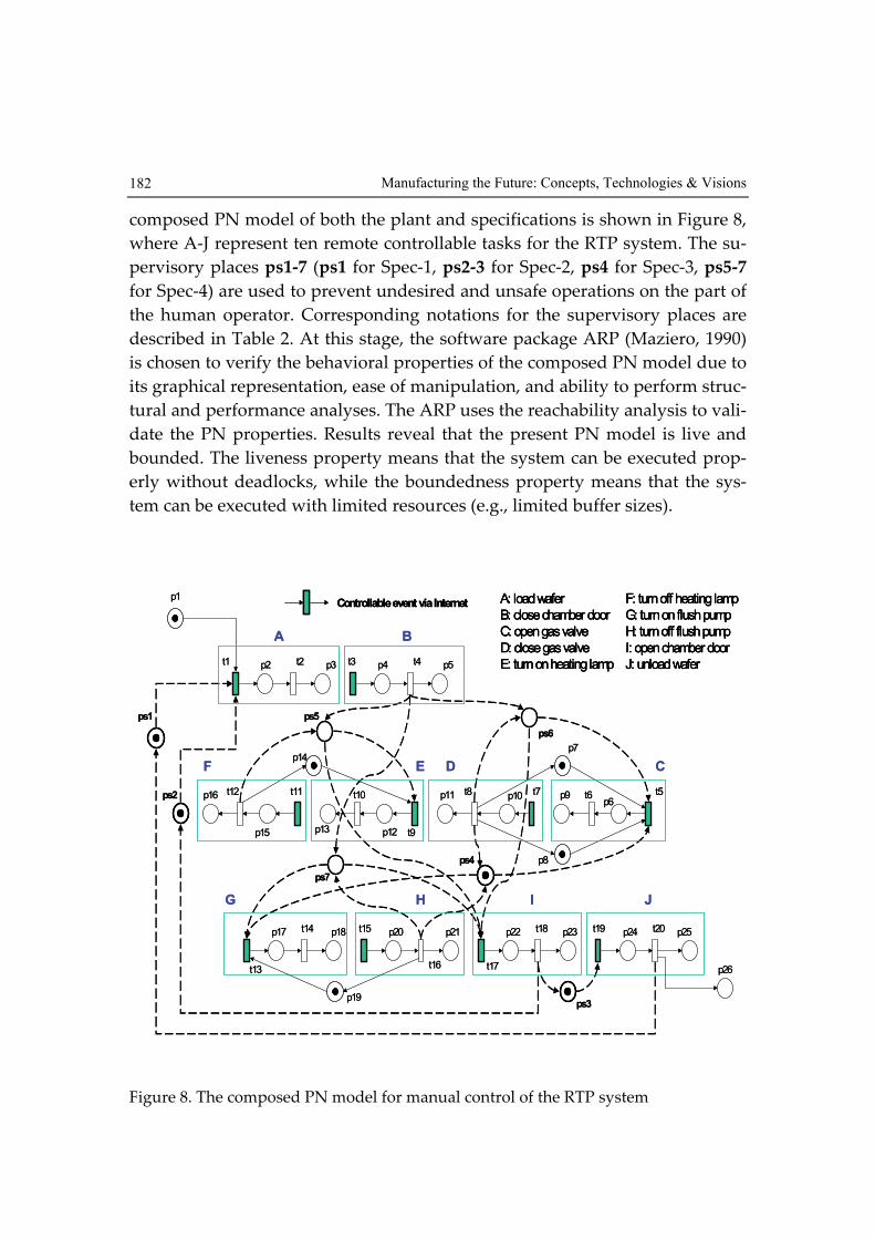
composed PN model of both the plant and specifications is shown in Figure 8,
where A-J represent ten remote controllable tasks for the RTP system. The su-
pervisory places ps1-7 (ps1 for Spec-1, ps2-3 for Spec-2, ps4 for Spec-3, ps5-7
for Spec-4) are used to prevent undesired and unsafe operations on the part of
the human operator. Corresponding notations for the supervisory places are
described in Table 2. At this stage, the software package ARP (Maziero, 1990)
is chosen to verify the behavioral properties of the composed PN model due to
its graphical representation, ease of manipulation, and ability to perform struc-
tural and performance analyses. The ARP uses the reachability analysis to vali-
date the PN properties. Results reveal that the present PN model is live and
bounded. The liveness property means that the system can be executed prop-
erly without deadlocks, while the boundedness property means that the sys-
tem can be executed with limited resources (e.g., limited buffer sizes).
p20 p21
t16
t15p17 p18t14
t13
p24 p25t20t19p22 p23t18
t17
ps2
p2 p3t2t1 p4 p5t4t3
p1
p6p9 t6 t5
p12p13
t10
t9
p10p11 t8 t7
p15
p16 t12 t11
p14
p8
p7
ps1
ps6
ps3
ps5
ps4
ps7
p26
p19
A
H IG
F E D C
B
J
A: load wafer
B: close chamber door
C: open gas valve
D: close gas valve
E: turn on heating lamp
F: turn off heating lamp
G: turn on flush pump
H: turn off flush pump
I: open chamber door
J: unload wafer
Controllable event via Internet
p20 p21
t16
t15p17 p18t14
t13
p24 p25t20t19p22 p23t18
t17
ps2
p2 p3t2t1 p4 p5t4t3
p1
p6p9 t6 t5
p12p13
t10
t9
p10p11 t8 t7
p15
p16 t12 t11
p14
p8
p7
ps1
ps6
ps3
ps5
ps4
ps7
p26
p19
A
H IG
F E D C
B
J
A: load wafer
B: close chamber door
C: open gas valve
D: close gas valve
E: turn on heating lamp
F: turn off heating lamp
G: turn on flush pump
H: turn off flush pump
I: open chamber door
J: unload wafer
A: load wafer
B: close chamber door
C: open gas valve
D: close gas valve
E: turn on heating lamp
F: turn off heating lamp
G: turn on flush pump
H: turn off flush pump
I: open chamber door
J: unload wafer
Controllable event via InternetControllable event via Internet
Figure 8. The composed PN model for manual control of the RTP system

Applications of Petri Nets to Human-in-the-Loop Control for Discrete… 183
Place Description
ps1 Spec-1: chamber is empty
ps2 Spec-2: chamber door is open
ps3 Spec-2: chamber door is open
ps4 Spec-3: gas is closed/pump is off
ps5 Spec-4: door is closed/lamp is off
ps6 Spec-4: door is closed/gas is closed
ps7 Spec-4: door is closed/pump is off
Table 2. Notations for supervisory places of PN in Figure 8
5.4 Implementation with Agent Technology
The system modeling and design developed in previous stages provide super-
visory control models for implementation with agent technology. The devel-
oped supervisory agent is implemented on the Mirle SoftPLC (80486-100
CPU), an advanced industrial PLC with built-in Web server and Java virtual
machine so that it can interpret the LLD, HTTP requests, and Java programs
(Mirle Automation Corporation, 1999; SoftPLC Corporation, 1999).
The developed HMI, shown in Figure 9, is carefully designed to make its web
pages more user-friendly and also to increase download speed by avoiding
unnecessary images. Since the client users will be mainly operators and engi-
neers, they will want effective information delivery and will not be interested
in flashy graphics (Shikli, 1997).
The current system status is placed on the left, the system message is in the
center, and the button control area is on the right. Figure 9 also shows the web
pages for manual control mode after the Open Valve button has just been
pushed (Step 3 in Section 5.1). In this situation, since one wafer is already in
the chamber and the door is closed, the Load Wafer and Unload Wafer but-
tons are both disabled by the supervisory agent to meet Spec-1 and Spec-2.
Moreover, the Turn_On Pump and Open Door buttons are disabled to meet
Spec-3 and Spec-4, respectively. Thus, the safety requirements of the RTP
processing are guaranteed as human operations are conducted.

Manufacturing the Future: Concepts, Technologies & Visions 184
Figure 9. Interactive web page in manual control mode at Step 3 of RTP processing
(seven buttons are enabled)
6. Application 2: A Two-Robot Remote Surveillance System
6.1 System Description
Figure 10 shows a human-computer interactive system (HCIS), in which a hu-
man operator issues a command to trigger a human-controlled (semi-
autonomous) robot and a computer controller automatically regulates a com-
puter-controlled (fullly autonomous) robot both with the status feedback from
the overall controlled system (i.e. both robots) through a network. Such HCIS
can be applied as a remote surveillance system, which is composed of one hu-
man-controlled robot (simplified as Robot-h) and one computer-controlled ro-
bot (simplified as Robot-c). These two robots are placed on a floor with five
rooms, and the moving directions for each robot are shown in Figure 11, re-
spectively.

Applications of Petri Nets to Human-in-the-Loop Control for Discrete… 185
The Robot-h and Robot-c must traverse each doorway in the direction indi-
cated. Moreover, in order to avoid possible collisions, Robot-h and Robot-c are
not allowed simultaneously in the same room during the surveillance period.
The initial states of the Robot-h and Robot-c are in R5 and R2, respectively.
Supervisory
Agent
Human
OperatorHuman
Command
Network
Computer
Controller
Controlled
System
Computer
Command
Human-Controlled
Robot
Computer-Controlled
Robot
Status
Feedback
Command
Advice
Command
Advice
Supervisory
Agent
Human
OperatorHuman
Command
Network
Computer
Controller
Controlled
System
Computer
Command
Human-Controlled
Robot
Computer-Controlled
Robot
Status
Feedback
Command
Advice
Command
Advice
Figure 10. A two-robot human-computer interactive system
R1
R5R4
R3R2
Robot-c
R1
R5R4
R3R2
Robot-h
(a) (b)
R1
R5R4
R3R2
Robot-c
R1
R5R4
R3R2
Robot-h
R1
R5R4
R3R2
Robot-c
R1
R5R4
R3R2
Robot-c
R1
R5R4
R3R2
Robot-h
R1
R5R4
R3R2
Robot-h
(a) (b)
Figure 11. The schematic diagram of the two-robot remote surveillance system with the mov-
ing directions for (a) human-controlled robot, and (b) computer-controlled robot.

Manufacturing the Future: Concepts, Technologies & Visions 186
6.2 PN-Based System Modeling
By applying the command/response concept and based on the system descrip-
tion, the PN model for the human-controlled robot is constructed as shown in
Figure 12 (a). It consists of 13 places and 16 transitions, respectively. On the
other hand, for the computer-controlled robot, the PN model is directly built
according to its located room, as shown in Figure 12 (b), which respectively
consists of 5 places and 6 transitions. Corresponding notation of both the PN
models is described in Table 3.
ph3 ph1ph2 th1
t1
ph8
ph6
ph5
ph4
ph7
ph9
ph10
ph11
ph12
ph13
th2
th3
th4
th5
th6
th7 th8
th9
th10
th11
th12
th13 th14
th15th16
Controllable events by the human
(a)
ph3 ph1ph2 th1
t1
ph8
ph6
ph5
ph4
ph7
ph9
ph10
ph11
ph12
ph13
th2
th3
th4
th5
th6
th7 th8
th9
th10
th11
th12
th13 th14
th15th16
Controllable events by the human
ph3 ph1ph2 th1
t1
ph8
ph6
ph5
ph4
ph7
ph9
ph10
ph11
ph12
ph13
th2
th3
th4
th5
th6
th7 th8
th9
th10
th11
th12
th13 th14
th15th16
ph3 ph1ph2 th1
t1
ph8
ph6
ph5
ph4
ph7
ph9
ph10
ph11
ph12
ph13
th2
th3
th4
th5
th6
th7 th8
th9
th10
th11
th12
th13 th14
th15th16
Controllable events by the humanControllable events by the human
(a)
pc1tc3 tc6
pc4pc2
pc5
tc2 tc5tc1 tc4
pc3 pc1tc3 tc6
pc4pc2
pc5
tc2 tc5tc1 tc4
pc3 pc1tc3 tc6
pc4pc2
pc5
tc2 tc5tc1 tc4
pc3
(b)
Figure 12. PN models of (a) human-controlled robot, and (b) computer-controlled robot

Applications of Petri Nets to Human-in-the-Loop Control for Discrete… 187
Place Description Transition Description
ph1 Robot-h is in R2 th1 Cmd: start moving to R1
ph2 Moving to R1 th2 Re: end moving to R1
ph3 Robot-h is in R1 th3 Cmd: start moving to R4
ph4 Moving to R4 th4 Re: end moving to R4
ph5 Robot-h is in R4 th5 Cmd: start moving to R2
ph6 Moving to R2 th6 Re: end moving to R2
ph7 Moving to R3 th7 Cmd: start moving to R3
ph8 Robot-h is in R3 th8 Re: end moving to R3
ph9 Moving to R5 th9 Cmd: start moving to R5
ph10 Robot-h is in R5 th10 Re: end moving to R5
ph11 Moving to R2 th11 Cmd: start moving to R2
ph12 Moving to R5 th12 Re: end moving to R2
ph13 Moving to R4 th13 Cmd: start moving to R5
th14 Re: end moving to R5
th15 Cmd: start moving to R4
th16 Re: end moving to R4
pc1 Robot-c is in R2 tc1 Move to R4
pc2 Robot-c is in R4 tc2 Move to R1
pc3 Robot-c is in R1 tc3 Move to R2
pc4 Robot-c is in R5 tc4 Move to R5
pc5 Robot-c is in R3 tc5 Move to R3
tc6 Move to R2
Table 3. Notation for the Petri nets in Figure 12
6.3 PN-Based Supervisor Synthesis
The five rooms represent the resources shared by the two robots. Since more
than one robot may require access to the same room, but in order to avoid col-
lisions, each room can only be allowed to have one robot at a time, operations
with collisions and deadlocks may thus occur. Hence, the objective is to design
a supervisor to insure the whole system against these undesired situations.
The required two main specifications are formulated as follows:

Manufacturing the Future: Concepts, Technologies & Visions 188
Spec-1: Collision-free motions: Robot-h or Robot-c moving to Room i is al
lowed only when Room i is available, where i = 1, 2, …, 5. Thus, we
have five sub-specifications denoted as Spec-1.1 to Spec-1.5.
Spec-2: Deadlock-free operations: No deadlock states occur throughout system
operation.
In the specification models, Spec-1.1 to Spec-1.5 are enforced by using the mu-
tual exclusion concept. The composed PN model of both the systems and
specifications is shown in Figure 13. The supervisory arcs are shown with
dashed lines and the places showing the supervisory positions are drawn
thicker than those showing the system positions. A supervisory place is mod-
eled as an input place of the transitions that need such a resource, and as an
output place of those that release this resource. Take an example of ps1 that
physically means Room 1 being available. It makes two transitions th1 and tc2
mutually exclusive. Intuitively, performance of th1 is only allowed if Room 1 is
available and tc2 has not yet been fired. If tc2 has been fired, th1 cannot be exe-
cuted until tc3 is given to signal that Room 1 is available again. Thus, only one
robot is allowed to be in Room 1 at any time, thereby avoiding the collision
there.
The supervisory places ps1 to ps5 (for Spec-1.1 to Spec-1.5, respectively) are
used to prevent the remote human operator and computer controller from is-
suing undesired commands leading to resource conflicts on the part of the sys-
tem. The corresponding notation for the supervisory places (ps1-ps5) is de-
scribed in Table 4.
Place Description
ps1 Spec-1.1: R1 is available.
ps2 Spec-1.2: R2 is available.
ps3 Spec-1.3: R3 is available.
ps4 Spec-1.4: R4 is available.
ps5 Spec-1.5: R5 is available.
ps6Spec-2.1: Robot-h is admitted into R1.
Robot-c is admitted into R4.
ps7 Spec-2.2: Robot-h is admitted into R3.
Robot-c is admitted into R5.
Table 4. Notation for the supervisory places in Figure 13
Applications of Petri Nets to Human-in-the-Loop Control for Discrete… 189
Controllable events by human
ps1
ph3 ph1ph2 th1
t1
ph8
ph6
ph5
ph4
ph7
ph9
ph10
ph11
ph12
ph13
th2
th3
th4 th5
th6
th7 th8
th9
th10th11
th12
th13
th14
th15th16
pc1tc3 tc6
pc4pc2
pc5
tc2 tc5tc1 tc4
pc3
ps3
ps2
ps4 ps5
Controllable events by humanControllable events by human
ps1
ph3 ph1ph2 th1
t1
ph8
ph6
ph5
ph4
ph7
ph9
ph10
ph11
ph12
ph13
th2
th3
th4 th5
th6
th7 th8
th9
th10th11
th12
th13
th14
th15th16
pc1tc3 tc6
pc4pc2
pc5
tc2 tc5tc1 tc4
pc3
ps3
ps2
ps4 ps5
Figure 13. Preliminary composed PN model of the remote surveillance system
6.4 System Verification and Deadlock Resolution
Again, the software package ARP (Maziero, 1990) is used to verify the behav-
ioral properties of the composed PN model using the reachability analysis. The
validation result shows that two deadlocks occur with the marked places {ph3,
pc2, ps2, ps3, ps5} and {ph8, pc4, ps1, ps2, ps4}, respectively. Figure 14 shows
the real situations of the two deadlock states, of which the physical meaning is
that if Room 1 (or Room 3) is occupied with Robot-h and Room 4 (or Room 5)
is held by Robot-c, respectively, then no new events can be fired by the human
or computer, and the system is deadlocked. Hence, for deadlock-free require-
ments, Spec-2 has two sub-specifications as follows:
Spec-2.1: Robot-h is allowed to enter Room 1 only when Robot-c is not in
Room 4, and vice versa.
Spec-2.2: Robot-h is allowed to enter Room 3 only when Robot-c is not in
Room 5, and vice versa.

Manufacturing the Future: Concepts, Technologies & Visions 190
As shown in Figure 15, ps6 and ps7 are further designed by using the mutual
exclusion concept and then combined with the PN model in Figure 13. Take an
example of ps6. It makes transitions th1 and tc1 mutually exclusive. That
means either Robot-h moving to R1 or Robot-c moving to R4 is allowed to per-
form at a time. If tc1 has been fired, th1 cannot be executed until tc2 is given to
signal that Robot-c is not in R4.
Validation results (with ps6 and ps7) reveal that the present PN model is dead-
lock-free, bounded, and reversible. The deadlock-free property means that the
system can be executed properly without deadlocks, while boundedness indi-
cates that the system can be executed with limited resources, and reversibility
implies that the initial system configuration is always reachable. The corre-
sponding notation for the supervisory places (ps6 and ps7) is described in Ta-
ble 4.
R1
R5R4
R3
R2Robot-h
Robot-c
Robot-h
Robot-c
Deadlock 1 Deadlock 2
R1
R5R4
R3
R2Robot-h
Robot-c
Robot-h
Robot-c
Deadlock 1 Deadlock 2
Figure 14. Two deadlock states of the PN model in the Figure 13
ps6
tc1
tc2
th1
th4
ps7
tc4
tc5
th7
th10
ps6
tc1
tc2
th1
th4
ps6
tc1
tc2
th1
th4
ps7
tc4
tc5
th7
th10
ps7
tc4
tc5
th7
th10
Figure 15. Supervisory places for the deadlock resolution

Applications of Petri Nets to Human-in-the-Loop Control for Discrete… 191
6.5 Discussions
On the part of the human-controlled robot, in the proposed supervisory
framework, the human behavior is advised and restricted to satisfy the specifi-
cations so that the collision and deadlock are avoid during the surveillance pe-
riod. As shown in Table 5, without supervisory control, the state space is 65,
including the undesired collision and deadlock states. By using our proposed
approach, in the preliminary supervision, i.e., only the collision-free specifica-
tion (Spec-1.1 to Spec-1.5) is enforced, the state space reduces to 44. Finally,
with the deadlock resolution, the state space is limited to 40 only. That means
the undesired collision and deadlock states will be successfully avoided dur-
ing the surveillance period. In this approach, the supervisor only consists of places
and arcs, and its size is proportional to the number of specifications that must be sat-
isfied.
Petri net
models
Unsupervised
system
Preliminary supervision
(with deadlocks)
Complete supervision
(deadlock-free)
Places 18 23 25
Transitions 22 22 22
State space 65 44 40
Table 5. Comparison between unsupervised and supervised systems
7. Conclusion
This chapter has presented a PN-based framework to design supervisors for
human-in-the-loop systems. The supervisor is systematically synthesized to
enforce the requirements. To demonstrate the practicability of the proposed
supervisory approach, an application to 1) the RTP system in semiconductor
manufacturing controlled over the Internet and 2) the two-robot remote sur-
veillance system are provided. According to the feedback status of the re-
motely located system, the designed supervisory agent guarantees that all re-
quested commands satisfy the desired specifications. On the part of human-

Manufacturing the Future: Concepts, Technologies & Visions 192
controlled systems, the developed supervisor can be implemented as an intel-
ligent agent to advise and guide the human operator in issuing commands by
enabling or disabling the associated human-controlled buttons. Hence, for
human-in-the-loop systems, the proposed approach would be also beneficial to
the human-machine interface design.
Future work includes the extension of specifications to timing constraints, the
multiple-operator access, and error recovery functions. Moreover, constructive
definition of the synthesis algorithm should be investigated. Also, for the scal-
ability of the supervisor synthesis, the hierarchical design can be further ap-
plied to more complex and large-scale systems.
8. References
Balemi, S.; Hoffmann, G. J.; Gyugyi, P.; Wong-Toi, H. & Franklin, G. F. (1993).
Supervisory control of a rapid thermal multiprocessor. IEEE Trans.
Automat. Contr., Vol. 38, No. 7, pp. 1040-1059.
Booch, G.; Rumbaugh, J. & Jacobson, I. (1999). The Unified Modeling Language
User Guide, Addison-Wesley, Reading, MA.
Bradshaw, J. M. (1997), Introduction to software agents, Software Agents, Brad-
shaw, J. M. Ed., Cambridge, MA: AAAI Press/MIT Press.
David, R. & Alla, H. (1994), Petri nets for modeling of dynamics systems– A
survey, Automatica, Vol. 30, No. 2, pp. 175-202.
Fair, R. B. (1993), Rapid Thermal Processing: Science and Technology, New York:
Academic.
Giua, A. & DiCesare, F. (1991), Supervisory design using Petri nets, Proceedings
of IEEE Int. Conf. Decision Contr., pp. 92-97, Brighton, England.
Huang, G. Q. & Mak, K. L. (2001), Web-integrated manufacturing: recent de-
velopments and emerging issues, Int. J. Comput. Integrated Manuf., Vol.
14, No. 1, pp. 3-13, (Special issue on Web-integrated manufacturing).
Kress, R. L., Hamel, W. R., Murray, P. & Bills, K. (2001), Control strategies for
teleoperated Internet assembly, IEEE/ASME Trans. Mechatronics, Vol. 6,
No. 4, pp. 410-416, (Focused section on Internet-based manufacturing
systems).
Lee, J. S. & Hsu, P. L. (2003), Remote supervisory control of the human-in-the-
loop system by using Petri nets and Java, IEEE Trans. Indu. Electron.,
Vol. 50, No. 3, pp. 431-439.

Applications of Petri Nets to Human-in-the-Loop Control for Discrete… 193
Lee, J. S. & Hsu, P. L. (2004), Design and implementation of the SNMP agents
for remote monitoring and control via UML and Petri nets, IEEE Trans.
Contr. Syst. Technol., Vol. 12, No. 2, pp. 293-302.
Lee, J. S.; Zhou M. C. & Hsu P. L. (2005), An application of Petri nets to super-
visory control for human-computer interactive systems, IEEE Transac-
tions on Industrial Electronics, Vol. 52, No. 5, pp. 1220-1226.
Maziero, C. A. (1990), ARP: Petri Net Analyzer. Control and Microinformatic
Laboratory, Federal University of Santa Catarina, Brazil.
Milner R. (1989), Communication and Concurrency. Englewood Cliffs, NJ: Pren-
tice Hall.
Mirle Automation Corporation (1999), SoftPLC Controller User’s Manual Version
1.2. Hsinchu, Taiwan.
Moody, J. O. & Antsaklis, P. J. (1998), Supervisory Control of Discrete Event sys-
tems Using Petri Nets. Boston, MA: Kluwer.
Murata, T. (1989), Petri nets: Properties, analysis, and applications, Proc. IEEE,
Vol. 77, No. 4, pp. 541-580.
Petri, C. A. (1962), Kommunikation mit Automaten. Bonn: Institut für Instrumen-
telle Mathematik, Schriften des IIM Nr. 2. English translation, Communi-
cation with Automata. New York: Griffiss Air Force Base, Tech.l Rep.
RADC-TR-65--377, Vol. 1, pages 1-Suppl. 1. 1966.
Ramadge, P. J. & Wonham, W. M. (1987), Supervisory control of a class of dis-
crete event processes, SIAM J. Contr. Optimiz., Vol. 25, No. 1, pp. 206-
230.
Ramadge, P. J. & Wonham, W. M. (1989), The control of discrete event systems,
Proc. IEEE, Vol. 77, No. 1, pp. 81-98.
Rasmussen, J., Pejtersen, A. M. & Goodstein, L. P. (1994), Cognitive Systems En-
gineering. New York, NY: John Wiley and Sons.
Shikli, P. (1997), Designing winning Web sites for engineers, Machine Design,
Vol. 69, No. 21, pp. 30-40.
SoftPLC Corporation (1999), SoftPLC-Java Programmer’s Toolkit. Spicewood, TX.
Uzam, M., Jones, A. H. & Yücel, I. (2000), Using a Petri-net-based approach for
the real-time supervisory control of an experimental manufacturing sys-
tem, Int. J. Adv. Manuf. Tech., Vol. 16, No. 7, pp. 498-515.
Weaver, A., Luo, J. & Zhang, X. (1999), Monitoring and control using the Inter-
net and Java, Proceedings of IEEE Int. Conf. Industrial Electronics, pp. 1152-
1158, San Jose, CA.
Wooldridge, M. & Jenkins, M. R. (1995), Intelligent agents: theory and practice,
Knowledge Engineering Review, Vol. 10, No. 2, pp. 115–152.

Manufacturing the Future: Concepts, Technologies & Visions 194
Yang, S. H., Chen, X. & Alty, J. L. (2002), Design issues and implementation of
Internet-based process control systems, Contr. Engin. Pract., Vol. 11, No.
6, pp. 709-720.
Zhou, M. C. & DiCesare, F. (1991), Parallel and sequential mutual exclusions
for Petri net modeling for manufacturing systems, IEEE Trans. Robot.
Automat., Vol. 7, No. 4, pp. 515-527.
Zhou, M. C. & Jeng, M. D. (1998), Modeling, analysis, simulation, scheduling,
and control of semiconductor manufacturing systems: A Petri net ap-
proach, IEEE Trans. Semicond. Manuf., Vol. 11, No. 3, pp. 333-357, (Spe-
cial section on Petri nets in semiconductor manufacturing).
Zurawski, R. & Zhou, M. C. (1994), Petri nets and industrial applications: a tu-
torial, IEEE Trans. Ind. Electron., Vol. 41, No. 6, pp. 567-583, (Special sec-
tion on Petri nets in manufacturing).

Manufacturing the FutureEdited by Vedran Kordic, Aleksandar Lazinica and Munir Merdan
ISBN 3-86611-198-3Hard cover, 908 pagesPublisher Pro Literatur Verlag, Germany / ARS, Austria Published online 01, July, 2006Published in print edition July, 2006
InTech EuropeUniversity Campus STeP Ri Slavka Krautzeka 83/A 51000 Rijeka, Croatia Phone: +385 (51) 770 447 Fax: +385 (51) 686 166www.intechopen.com
InTech ChinaUnit 405, Office Block, Hotel Equatorial Shanghai No.65, Yan An Road (West), Shanghai, 200040, China
Phone: +86-21-62489820 Fax: +86-21-62489821
The primary goal of this book is to cover the state-of-the-art development and future directions in modernmanufacturing systems. This interdisciplinary and comprehensive volume, consisting of 30 chapters, covers asurvey of trends in distributed manufacturing, modern manufacturing equipment, product design process,rapid prototyping, quality assurance, from technological and organisational point of view and aspects of supplychain management.
How to referenceIn order to correctly reference this scholarly work, feel free to copy and paste the following:
Jin-Shyan Lee and Pau-Lo Hsu (2006). Applications of Petri Nets to Human-in-the-Loop Control for DiscreteAutomation Systems, Manufacturing the Future, Vedran Kordic, Aleksandar Lazinica and Munir Merdan (Ed.),ISBN: 3-86611-198-3, InTech, Available from:http://www.intechopen.com/books/manufacturing_the_future/applications_of_petri_nets_to_human-in-the-loop_control_for_discrete_automation_systems

© 2006 The Author(s). Licensee IntechOpen. This chapter is distributed under the terms of theCreative Commons Attribution-NonCommercial-ShareAlike-3.0 License, which permits use,distribution and reproduction for non-commercial purposes, provided the original is properly citedand derivative works building on this content are distributed under the same license.