Application Reference Number: WWO10001 Tunnel and Bridge Assessments · PDF fileTunnel and...
54
Tunnel and Bridge Assessments Eastern Zone Cable and Wireless Utility Bridge over Limehouse Cut at A13 Commercial Road Doc Ref: 9.15.90 Folder 105 September 2013 DCO-DT-000-ZZZZZ-091500 Thames Tideway Tunnel Thames Water Utilities Limited Application for Development Consent Application Reference Number: WWO10001
Transcript of Application Reference Number: WWO10001 Tunnel and Bridge Assessments · PDF fileTunnel and...

Tunnel and Bridge AssessmentsEastern ZoneCable and Wireless Utility Bridge over Limehouse Cut at A13 Commercial RoadDoc Ref: 9.15.90
Folder 105 September 2013DCO-DT-000-ZZZZZ-091500 U
tilit
y Br
idge
ove
r Lim
ehou
se C
ut
at A
13 C
omm
erci
al R
oad
Thames Tideway Tunnel Thames Water Utilities Limited
Application for Development ConsentApplication Reference Number: WWO10001


PRIVATE AND CONFIDENTIAL
Utillity Bridge over Limehouse Cut at A13 Commercial Road 307-RG-TPI-BR483-000001 Revision - AB Date approved -
i Printed 06/09/2012
PRIVATE AND CONFIDENTIAL
Thames Tunnel
Assessment Report
Utility Bridge over Limehouse Cut at A13 Commercial Road
List of contents
Page number
1 Introduction ...................................................................................................... 4
1.1 Project Description .................................................................................. 4
1.2 Works at Utility Bridge over Limehouse Cut at A13 Commercial Road ... 4
1.3 Scope of Assessment .............................................................................. 4
1.4 Other Third Party Interface / Related Assessments ................................. 5
2 Structure Details .............................................................................................. 6
2.1 Description of Structure ........................................................................... 6
2.2 Structure Type ......................................................................................... 6
2.3 Foundation Type ...................................................................................... 7
2.4 Span Arrangements ................................................................................. 7
2.5 Articulations Arrangements...................................................................... 7
2.6 Year of Construction ................................................................................ 7
3 Inspection and Data Collection ....................................................................... 8
3.1 Inspection Summary ................................................................................ 8
3.2 Reference Data ....................................................................................... 8
3.3 Adequacy of Data and Assumptions ........................................................ 8
4 Ground Movement Assessment ..................................................................... 9
4.1 Method of Ground Movement Calculation ............................................... 9
4.2 Ground Conditions ................................................................................. 10
4.3 Ground Movement Results .................................................................... 10
5 Structural Assessment .................................................................................. 16
5.1 General .................................................................................................. 16
5.2 Reference Documents ........................................................................... 16
5.3 Structure Records .................................................................................. 16
5.4 Assumptions and Codes used in the Assessment ................................. 16
5.5 Structural Assessment Methodology ..................................................... 17
5.6 Assessment Results .............................................................................. 17
6 Monitoring and Mitigation ............................................................................. 22

PRIVATE AND CONFIDENTIAL
Utillity Bridge over Limehouse Cut at A13 Commercial Road 307-RG-TPI-BR483-000001 Revision - AB Date approved -
ii Printed 06/09/2012
PRIVATE AND CONFIDENTIAL
6.1 Route-Wide Monitoring .......................................................................... 22
6.2 Asset-Specific Monitoring and Mitigation ............................................... 22
7 Conclusions and Recommendations ........................................................... 23
7.1 Conclusions ........................................................................................... 23
7.2 Recommendations ................................................................................. 24
8 Further Work ................................................................................................... 25
Appendices ............................................................................................................. 26
Appendix A – Location Plan and Proposed Tunnel Alignment .......................... 27
Appendix B – Settlement Trough .......................................................................... 28
Appendix C – Certificate of Assessment and Checking (Structural) ................. 29
Appendix D – Certificate of Assessment and Checking (Geotechnical) ............ 30
List of tables
Page number
Table 1: Utility Bridge calculated ground movements at the tunnel completion ........ 11
Table 2: Utility Bridge – horizontal ground movements parallel to the bridge centreline ................................................................................................................. 13
Table 3: Utility Bridge – horizontal ground movements perpendicular to the bridge centreline ................................................................................................. 14
List of figures
Page number
Figure 1: Utility Bridge over Limehouse Cut – South Elevation .................................. 6
Figure 2: Utility Bridge over Limehouse Cut – Structural Diagram .............................. 7
Figure 3: Utility Bridge orientation plan ..................................................................... 11
Figure 4: Vertical settlement profiles at foundation level as the TBM progresses below the Utility Bridge. ........................................................................... 12
Figure 5: Summary of vertical movements at the Utility Bridge superstructure level. 12
Figure 6: Horizontal ground movement parallel to the bridge centreline at foundation level as the TBM progresses below the Utility Bridge. ............................. 13
Figure 7: Summary of horizontal movements parallel to the bridge centreline at the Utility Bridge superstructure level. ........................................................... 13
Figure 8: Horizontal ground movement perpendicular to the bridge centreline at foundation level as the TBM progresses below the Utility Bridge. ........... 14
Figure 9: Summary of horizontal movements perpendicular to the bridge centreline at the Utility Bridge superstructure level. ..................................................... 15

PRIVATE AND CONFIDENTIAL
Utillity Bridge over Limehouse Cut at A13 Commercial Road 307-RG-TPI-BR483-000001 Revision - AB Date approved -
iii Printed 06/09/2012
PRIVATE AND CONFIDENTIAL
Figure 10: Utility Bridge south elevation – vertical bending moment [kNm] due to vertical settlement [mm] ........................................................................... 18
Figure 11: Utility Bridge south elevation – steel beam stress [N/mm2] due to vertical settlement [mm] ....................................................................................... 18
Figure 12: Utility Bridge south elevation – steel beam compression [kN] due to horizontal ground movement parallel to the bridge centreline [mm]......... 18
Figure 13: Utility Bridge south elevation – steel beam compressive stress [N/mm2] due to horizontal ground movement parallel to the bridge centreline [mm] ................................................................................................................. 19
Figure 14: Utility Bridge plan – horizontal bending moment [kNm] due to horizontal ground movement perpendicular to the bridge centreline [mm] ............... 19
Figure 15: Utility Bridge plan – steel beam stress [N/mm2] due to horizontal ground movement perpendicular to the bridge centreline [mm] ........................... 19
List of abbreviations
CSO Combined Sewer Overflow
TT Thames Tunnel
PBA Peter Brett Associates
STW Sewage Treatment Works
EPB Earth Pressure Balance
TBM Tunnel Boring Machine

PRIVATE AND CONFIDENTIAL
Utillity Bridge over Limehouse Cut at A13 Commercial Road 307-RG-TPI-BR483-000001 Revision - AB Date approved -
4 Printed 06/09/2012
PRIVATE AND CONFIDENTIAL
1 Introduction
1.1 Project Description
Thames Water is currently progressing with its planned London Thames Tideway Improvements programme. The improvement works consists of construction of two new tunnels, the Thames Tunnel and the Lee Tunnel, together with a programme of Sewage Treatment Works (STW) upgrades.
Construction of the Thames Tunnel (TT), stretching approximately 23km under the River Thames from West London to East London, is due to commence in 2014. The Tunnel will intercept the flow from the most polluting Combined Sewer Overflows (CSO) of the existing system. The planned alignment runs mainly beneath the River Thames at depths of up to 40m below the river bed in order to minimise the potential impact on third party assets.
The main Thames Tunnel is currently planned to be 7.2m internal diameter with a primary and secondary lining giving an effective 8.5m external diameter with an excavated cut diameter of 8.8m. A number of smaller additional tunnels are required to connect the existing CSOs to the main tunnel.
As part of the works, Thames Tunnel Project Team has appointed Peter Brett Associates (PBA), and their sub-consultant Arup, to undertake an assessment of the effects of tunnelling-induced ground movement on the Utility Bridge over Limehouse Cut at A13 Commercial Road.
1.2 Works at Utility Bridge over Limehouse Cut at A13 Commercial Road
The main Thames Tunnel is to be constructed west of the Utility Bridge over Limehouse Cut at A13 Commercial Road running northeast between Limehouse and Bromley-by-Bow, at a depth of 55.3m below ground level. The excavated diameter of the tunnel will be 8.8m, internal finished diameter 7.2m.
Refer to the drawing included in Appendix A for a location plan of the bridge and the proposed alignment of the Thames Tunnel.
1.3 Scope of Assessment
The scope is limited to assessing the Utility Bridge over Limehouse Cut at A13 Commercial Road for the effects of ground movements due to the proposed construction of the Thames Tunnel in accordance with the Approval-in-Principle document no. 307-EA-TPI-BR483-000001.
The assessment has determined the differences in load and serviceability effects due to the tunnelling works and does not represent a full assessment of the capacity of the structure.

PRIVATE AND CONFIDENTIAL
Utillity Bridge over Limehouse Cut at A13 Commercial Road 307-RG-TPI-BR483-000001 Revision - AB Date approved -
5 Printed 06/09/2012
PRIVATE AND CONFIDENTIAL
Reference should be made to the Approval-in-Principle, which has been issued separately to this document, for the detailed scope of work and input parameters for the assessment.
1.4 Other Third Party Interface / Related Assessments
The adjacent Britannia Bridge highway bridge, the Limehouse Cut canal walls, and the retaining walls running parallel to the canal are the subject of separate detailed assessments commissioned by Thames Tunnel.

PRIVATE AND CONFIDENTIAL
Utillity Bridge over Limehouse Cut at A13 Commercial Road 307-RG-TPI-BR483-000001 Revision - AB Date approved -
6 Printed 06/09/2012
PRIVATE AND CONFIDENTIAL
2 Structure Details
2.1 Description of Structure
The Utility Bridge over Limehouse Cut at A13 Commercial Road is located over Limehouse Cut south of the Britannia Bridge that carries the A13 Commercial Road. It is a steel three span bridge carrying utilities over the Limehouse Cut. The structure is believed to be owned by Cable and Wireless.
For photographs and description of the condition of the structure, reference should be made to the Inspection Report 307-RI-TPI-BR483-000001.
2.2 Structure Type
2.2.1 Superstructure
The Utility Bridge over Limehouse Cut at A13 Commercial Road is formed of modern rolled steel girders supported across two piers, spanning 12.5m pier to pier and approximately 2.5m from the east pier and 4m from the west pier to the end of the bridge. Refer to Figure 1 below.
Figure 1: Utility Bridge over Limehouse Cut – South Elevation
The two main girders are estimated to be 457 x 152 UB sections; spanning between the bottom flanges of these girders are flat plate sections roughly 1m in length which are bolted to the bottom flanges.
A thin ‘weather’ plate covers the bridge and is slightly curved.
Splice plates are visible on both the flange and web of the main girders as marked in Figure 1 above.

PRIVATE AND CONFIDENTIAL
Utillity Bridge over Limehouse Cut at A13 Commercial Road 307-RG-TPI-BR483-000001 Revision - AB Date approved -
7 Printed 06/09/2012
PRIVATE AND CONFIDENTIAL
2.2.2 Substructure
The eastern and western piers are in the form of a rectangular braced frame made up of EA 150x150 sections bolted together.
The bridge curves down into the ground at the western end and appears to be encased in concrete at ground level. The eastern end of the bridge appears to be built into a brick retaining wall.
2.3 Foundation Type
Foundations appear to be concrete footings visible at the base of the western end and pier of the utility bridge. It is assumed that similar foundations exist at the eastern end and pier but this could not be confirmed on site due to access arrangements. No information is currently available on the foundation depth but there is no evidence of settlement or other foundation problems, from the areas that were visible during the inspection.
2.4 Span Arrangements
The structure is a three span utility bridge. Refer to Figure 2 for span lengths.
Figure 2: Utility Bridge over Limehouse Cut – Structural Diagram
2.5 Articulations Arrangements
There are no bearings or expansion joints anywhere on the structure. The ends of the bridge are built into brick retaining walls on both ends of the structure although it is unlikely that moment connection is achieved, thus the structure will be considered as a three span continuous beam as shown in Figure 2 above.
2.6 Year of Construction
The year of construction is not known.

PRIVATE AND CONFIDENTIAL
Utillity Bridge over Limehouse Cut at A13 Commercial Road 307-RG-TPI-BR483-000001 Revision - AB Date approved -
8 Printed 06/09/2012
PRIVATE AND CONFIDENTIAL
3 Inspection and Data Collection
3.1 Inspection Summary
A visual inspection of the bridge was carried out from publicly accessible areas on 29th May 2012. The inspection determined that the visible elements of the Utility Bridge over Limehouse Cut at A13 Commercial Road are generally in good condition.
Reference should be made to the Inspection Report 307-RI-TPI-BR483-000001 for a more detailed description of the condition of the structure and photographs. A summary of the findings is given below:
• A condition factor of 1.0 will be used for assessment of the steel structure,
• There are no finishes, or structural details, that are particularly sensitive to the effects of foundation movements.
3.2 Reference Data
No previous inspection or assessment reports or any record drawings have been received for this structure to date.
The line and level of the tunnel has been taken from the following alignments:
• Abbey Mills Route – Provisional Horizontal Alignment for Phase 2 Consultation. CAD File Ref: 100-DO-DES-00000-017402-AL
• Abbey Mills Route – Provisional Vertical Alignment for Phase 2 Consultation. CAD File Ref: 100-DO-DES-00000-017423-AI
3.3 Adequacy of Data and Assumptions
Below the substructure, foundation details are unknown. It has been assumed that the foundation level, for ground movement assessment, is at a maximum of 4m below ground level.
No additional assumptions were required in order to proceed with the assessment.

PRIVATE AND CONFIDENTIAL
Utillity Bridge over Limehouse Cut at A13 Commercial Road 307-RG-TPI-BR483-000001 Revision - AB Date approved -
9 Printed 06/09/2012
PRIVATE AND CONFIDENTIAL
4 Ground Movement Assessment
This section describes the methods of “Greenfield” ground movement calculation, the methods of assessing the ground movement effects on the bridge and gives the results for movements of the structure.
4.1 Method of Ground Movement Calculation
Sub-surface greenfield ground movements are calculated using empirical methods, Mair et al. (1993) and Taylor (1995), where a settlement trough perpendicular to the new tunnel can be estimated using an inverted normal probability curve (Gaussian curve). The three dimensional form of movement is calculated using the Attewell & Woodman (1982) methodology. This methodology is used by the Oasys program XDisp which has been used to carry out these calculations.
For tunnelling in London Clay, Lambeth Group, Thanet Sand and Chalk and where no geological anomalies such as scour holes have been detected, a volume loss of 1% in accordance with Thames Tunnel’s moderately conservative value has been adopted. The adopted value is conservative when compared with recorded parameters for similar tunnel projects in London. Experience from Channel Tunnel Rail Link Contract 220 (CTRL), indicates that an average volume loss of 0.5% was achieved for tunnelling with an 8.11m diameter EPB TBM even in soft ground conditions, Wongsaroj et al (2006).
A trough width parameter, k of 0.5 at ground surface has been used for the assessment. The k value at any particular elevation is derived from an empirical equation in relation to depth below ground surface and distance from surface to tunnel axis level using the Mair et al. (1993) method.
The effect of the longitudinal “bow” wave settlement on the bridge supports as the TBM progresses has been assessed. Settlement with TBM progress is simulated as discrete tunnel sequence steps as it approaches and passes underneath the bridge, based on an estimated TBM progress of 10m/day.
4.1.1 Geotechnical References
a. Attewell P B and Woodman J P (1982). Predicting the dynamics of ground settlement and its derivatives caused by tunnelling in soil. Ground Engineering, November 1982, 13 - 36.
b. Mair R. J., Taylor R. N. and Bracegirdle A. (1993). Subsurface settlement profiles above clay in tunnels. Géotechnique 43 No. 2, pp. 315-320.
c. Burland J B (1995) Assessment of risk of damage to buildings due to tunnelling and excavation, Invited Special Lecture: 1st International Conference of Earthquake Geotechnical Engineering, IS Tokyo, 1995.

PRIVATE AND CONFIDENTIAL
Utillity Bridge over Limehouse Cut at A13 Commercial Road 307-RG-TPI-BR483-000001 Revision - AB Date approved -
10 Printed 06/09/2012
PRIVATE AND CONFIDENTIAL
d. Taylor R N (1995), Tunnelling in soft ground in the UK. In: Underground. Construction in Soft Ground. K Fujita and O Kusakabe (Eds). Balkema. pp123-126.
e. Wongsaroj J, Borghi F X, Soga K, Mair R J, Sugiyama T, Hagiwara T and Bowers K H. Effect of TBM driving parameters on ground surface movements: Channel Tunnel Rail Link Contract 220. Geotechnical aspects of underground construction in soft ground, Bakker et al (eds), 2006.
4.2 Ground Conditions
Review of borehole logs at the bridge/tunnel interface has been undertaken in order to confirm the stratigraphy as indicated on Thames Tunnel drawings (refer to the settlement trough in Appendix B). The review determined that the tunnel is located within structured chalk. No geological anomalies were identified during the review.
4.3 Ground Movement Results
On completion of tunnel construction, the main effect of ground movement will be vertical settlement and horizontal ground movement (parallel and perpendicular to the bridge centreline) towards the tunnel. The effect of ground slope, causing rotation of the bridge foundations toward the tunnel, will also be considered.
The main Thames Tunnel is to be constructed west of the Utility Bridge over Limehouse Cut at A13 Commercial Road running northeast between Limehouse and Bromley-by-Bow, at a depth of 55.3m below ground level. The excavated diameter of the tunnel will be 8.8m, internal finished diameter 7.2m.
Calculated ground movements vary with foundation depth. For Utility Bridge over Limehouse Cut at A13 Commercial Road, the foundation level was estimated, as the actual depth of foundation is not known.
Considering the difference in ground movements between River Bed Level and Foundation Level, it can be seen that there is little difference in the magnitude of the ground movements. For differential vertical settlements and horizontal ground movements the more onerous values are those calculated at foundation level. Therefore the values at assumed foundation level will be used in further assessment.
The calculated ground movements are tabulated below (see Table 1). In addition, the settlement trough is shown in Appendix B. For orientation reference should be made to Figure 3.

PRIVATE AND CONFIDENTIAL
Utillity Bridge over Limehouse Cut at A13 Commercial Road 307-RG-TPI-BR483-000001 Revision - AB Date approved -
11 Printed 06/09/2012
PRIVATE AND CONFIDENTIAL
Figure 3: Utility Bridge orientation plan
Table 1: Utility Bridge calculated ground movements at the tunnel completion
West [mm]
East [mm]
Vertical settlement Ground Level 8.4 7.0
Foundation 8.8 7.1
Horizontal Displacement (parallel)
Ground Level 1.6 1.9
Foundation 1.8 2.1
Horizontal Displacement (perpendicular)
Ground Level 1.2 1.4
Foundation 1.3 1.5
4.3.1 Vertical settlements
Vertical movements in the bridge elevation are at their greatest on completion of the tunnel construction. The maximum vertical settlement differential between east and west bridge ends also occurs at the tunnel completion. Refer to Figure 4 for a graph showing how the movement develops as the tunnel is constructed and to Figure 5 below for a summary of the calculated effects.
Parallel
(+ve)
Perpendicular (+ve)

PRIVATE AND CONFIDENTIAL
Utillity Bridge over Limehouse Cut at A13 Commercial Road 307-RG-TPI-BR483-000001 Revision - AB Date approved -
12 Printed 06/09/2012
PRIVATE AND CONFIDENTIAL
Figure 4: Vertical settlement profiles at foundation level as the TBM progresses below the Utility Bridge.
Figure 5: Summary of vertical movements at the Utility Bridge superstructure level.
As the bridge substructure is narrow at approximately 1m, the difference in the vertical movements between the bridge centreline and corners of the foundations will be negligible and will not be further considered.

Utillity Bridge over Limehouse Cut at A13 Commercial Road 307-RG-TPI-BR483-000001 Revision - AB Date approved -
4.3.2 Horizontal ground movements
Horizontal movements parallel to the bridge centre line in plan are at their greatest on completion of the tunnel construction. Refer to Figure 6. The slope of the ground (estimated from the settlement trough) beneath the bridge foundations willsuperstructure level. Figure 7 below.
Table 2: Utility Bridge bridge centreline
Ground movement parallel to the bridge centre line
[mm]
West 1.8
East 2.1
Figure 6: Hcentreline at foundation level as the TBM progresses below
Figure 7: Summary of horizontal movements parallel to the bridge centreline at the
PRIVATE AND CONFIDENTIAL
13
PRIVATE AND CONFIDENTIAL
Horizontal ground movements – parallel to the bridge centreline
Horizontal movements parallel to the bridge centre line in plan are at their greatest on completion of the tunnel construction. Refer to Figure 6. The slope of the ground (estimated from the settlement trough) beneath the bridge foundations will further increase the values of this movement at the superstructure level. The final values are summarised in Table 2 and
Bridge – horizontal ground movements parallel to the bridge centreline
movement parallel to the bridge centre line
Ground slope parallel to the bridge centreline
Additional horizontal parallel movement at the superstructure level due to the ground slope
1: [mm]
14000 0.4
14000 0.4
Horizontal ground movement parallel to the bridge centreline at foundation level as the TBM progresses below
Bridge.
: Summary of horizontal movements parallel to the bridge centreline at the Utility Bridge superstructure level.
Printed 06/09/2012
centreline
Horizontal movements parallel to the bridge centre line in plan are at their greatest on completion of the tunnel construction. Refer to Figure 6. The slope of the ground (estimated from the settlement trough) beneath the
further increase the values of this movement at the The final values are summarised in Table 2 and
horizontal ground movements parallel to the
Total parallel horizontal movement at the bridge superstructure level
[mm]
2.2
2.5
orizontal ground movement parallel to the bridge centreline at foundation level as the TBM progresses below the Utility
: Summary of horizontal movements parallel to the bridge Bridge superstructure level.

PRIVATE AND CONFIDENTIAL
Utillity Bridge over Limehouse Cut at A13 Commercial Road 307-RG-TPI-BR483-000001 Revision - AB Date approved -
14 Printed 06/09/2012
PRIVATE AND CONFIDENTIAL
4.3.3 Horizontal ground movements – perpendicular to the bridge centreline
The direction of the horizontal movement perpendicular to the bridge centre line in plan varies with the location of the TBM. In the first stage the bridge supports move horizontally in the southern direction and towards the approaching TBM. In the second stage the bridge supports move horizontally in the northern direction as the tunnel construction progresses below and away from the structure. The magnitude of movement depends on the position of the bridge support in relation to the tunnel construction. Refer to Figure 8.
The horizontal movement at the superstructure level will be increased due to the ground slope beneath the bridge foundations perpendicular to the bridge centre line. The final values are summarised in Table 3 and Figure 9 below.
Table 3: Utility Bridge – horizontal ground movements perpendicular to the bridge centreline
Ground movement perpendic-ular to the bridge centre line
Ground slope perpendic-ular to the bridge centreline
Additional horizontal perpendicular movement at the superstructure level due to the ground slope
Total perpendicular horizontal movement at the bridge superstructure level
[mm] 1: [mm] [mm]
West 1.3 25000 0.2 1.5
East 1.5 25000 0.2 1.7
Figure 8: Horizontal ground movement perpendicular to the bridge centreline at foundation level as the TBM progresses below the Utility
Bridge.

PRIVATE AND CONFIDENTIAL
Utillity Bridge over Limehouse Cut at A13 Commercial Road 307-RG-TPI-BR483-000001 Revision - AB Date approved -
15 Printed 06/09/2012
PRIVATE AND CONFIDENTIAL
Figure 9: Summary of horizontal movements perpendicular to the bridge centreline at the Utility Bridge superstructure level.

PRIVATE AND CONFIDENTIAL
Utillity Bridge over Limehouse Cut at A13 Commercial Road 307-RG-TPI-BR483-000001 Revision - AB Date approved -
16 Printed 06/09/2012
PRIVATE AND CONFIDENTIAL
5 Structural Assessment
5.1 General
A structural assessment has been undertaken for the bridge to determine the effects of tunnelling-induced ground movement on the structure. The structural assessment uses information gained from the inspection, to assess any impact that may arise due to the induced ground movements. The inspection has verified, as far as possible within the limitations of public access, the current condition of the bridge.
The assessment has determined the differences in load and serviceability effects due to the tunnelling works and does not represent a full assessment of the capacity of the structure. In addition the assessment considered whether monitoring or mitigation works would be required to accommodate the effects of the ground movement.
5.2 Reference Documents
The assessment has been carried out in accordance with the signed Approval-in-Principle, document no. 307-EA-TPI-BR483-000001.
5.3 Structure Records
For the list of information that has been used in the assessment of the Utility Bridge over Limehouse Cut at A13 Commercial Road refer to section 3.2 above.
5.4 Assumptions and Codes used in the Assessment
5.4.1 Assumptions
It should be noted that the following simplifications and assumptions have been made during Utility Bridge over Limehouse Cut at A13 Commercial Road assessment as it is not intended to be a full bridge capacity assessment:
• The structure is a continuous three span steel beam. The canal span is supported by flexible columns pinned at both top and bottom. The end supports are built into the adjacent brick structures but it is assumed that no moment restraint is provided. Refer to Figure 2 for assumed structural diagram.
• Assumptions have been made regarding the section size of the bridge main elements based on information gathered during visual inspection. The section size of the main bridge beams has been assumed as UB457x152x82. The section of the bridge supporting frame has been assumed as EA150x150x18
5.4.2 List of Codes

PRIVATE AND CONFIDENTIAL
Utillity Bridge over Limehouse Cut at A13 Commercial Road 307-RG-TPI-BR483-000001 Revision - AB Date approved -
17 Printed 06/09/2012
PRIVATE AND CONFIDENTIAL
• BD 2/05 Technical Approval of Highway Structures
• BD 21/01 The Assessment of Highway Bridges and Structures.
• BA 16/97 The Assessment of Highway Bridges and Structures. Including amendments 1 and 2
• BD 37/01 Loads for Highway Bridges.
• BD 56/10 The Assessment of Steel Highway Bridges and Structures
5.5 Structural Assessment Methodology
At the Utility Bridge over Limehouse Cut at A13 Commercial Road, on completion of tunnel construction, the main effect is a settlement trough with associated vertical and horizontal ground movements.
The structural assessment was undertaken to determine the impact of the ground movement from the tunnelling and is reported below.
5.5.1 Bridge superstructure
The superstructure of the Utility Bridge consists of a three span continuous steel beam. Therefore the assessment covered checks of stress increase in the main structural elements due to the tunnelling induced ground movements.
5.5.2 Bridge substructures and foundations
The Utility Bridge is supported by a steel frames on both sides of the Limehouse Cut. These are assumed pinned at both top and bottom. Therefore no stresses will be induced in the bridge substructure due to the tunnelling works.
The foundations are located behind the existing Limehouse Cut canal walls. No information is currently available on the foundations of the Utility Bridge. It is expected that the foundation will be either masonry or concrete. There is no evidence of settlement or other foundation problems.
5.6 Assessment Results
5.6.1 Bridge superstructure
A) Vertical settlement
The main bridge element is a three span continuous beam as show in Figure 2 above. There will be an additional bending moment induced in this beam due to the differential support settlement. The differential vertical settlement is small at 1.7mm and the existing beam is not overly stiff with the span to depth ratio of 27. The induced stresses in the steel beam due to the differential vertical settlement are small at a maximum of 2.1 N/mm2 (Figure 11) which is approximately 1% of the minimum characteristic yield strength of the steel of 230 N/mm2 as assumed in accordance with BD21/01.

PRIVATE AND CONFIDENTIAL
Utillity Bridge over Limehouse Cut at A13 Commercial Road 307-RG-TPI-BR483-000001 Revision - AB Date approved -
18 Printed 06/09/2012
PRIVATE AND CONFIDENTIAL
Figure 10: Utility Bridge south elevation – vertical bending moment [kNm] due to vertical settlement [mm]
Figure 11: Utility Bridge south elevation – steel beam stress [N/mm2] due to vertical settlement [mm]
Based on the above it is concluded that the differential vertical settlement will have negligible effect on the Utility Bridge carrying capacity.
B) Horizontal movement parallel to the bridge centreline
The horizontal ground movement parallel to the bridge centreline is towards the tunnel centreline. As the tunnel is located behind the west end of the bridge both supports will move in one direction resulting in small 0.3mm differential movement at the superstructure level. The west support moves less than the east support resulting in overall span shortening of 0.3mm. Refer to Figure 7. The induced stresses in the steel beam due to the differential ground movement parallel to the bridge centreline are small at maximum of 3.3 N/mm2 (Figure 13) which is approximately 1.5% of the minimum characteristic yield strength of the steel of 230 N/mm2 as assumed in accordance with BD21/01. This is conservative as the bridge is curved as shown in Figure 5 and therefore it is likely that the span shortening will be accommodated by flexure of the beams.
Figure 12: Utility Bridge south elevation – steel beam compression [kN] due to horizontal ground movement parallel to the bridge
centreline [mm]
-3.228
3.030 1.7001.700
-2.055
1.9281.7001.700
-33.99
0.3000

PRIVATE AND CONFIDENTIAL
Utillity Bridge over Limehouse Cut at A13 Commercial Road 307-RG-TPI-BR483-000001 Revision - AB Date approved -
19 Printed 06/09/2012
PRIVATE AND CONFIDENTIAL
Figure 13: Utility Bridge south elevation – steel beam compressive stress [N/mm2] due to horizontal ground movement parallel to the
bridge centreline [mm]
Based on the above it is concluded that the differential horizontal ground movement parallel to the bridge centreline will have negligible effect on the Utility Bridge carrying capacity.
C) Horizontal movement perpendicular to the bridge centreline
The horizontal ground movement perpendicular to the bridge centreline is towards the tunnel centreline. The west support moves less than the east support resulting in small differential movement of 0.2mm. Refer to Figure 8. The induced stresses in the steel beam due to the differential ground movement perpendicular to the bridge centreline are small at maximum of 0.1 N/mm2 (Figure 15) which is approximately 0.05% of the minimum characteristic yield strength of the steel of 230 N/mm2 as assumed in accordance with BD21/01.
Figure 14: Utility Bridge plan – horizontal bending moment [kNm] due to horizontal ground movement perpendicular to the bridge
centreline [mm]
Figure 15: Utility Bridge plan – steel beam stress [N/mm2] due to horizontal ground movement perpendicular to the bridge centreline
[mm]
Based on the above it is concluded that the differential horizontal ground movement perpendicular to the bridge centreline will have negligible effect on the Utility Bridge carrying capacity. It is also noted that the bridge is supported by flexible frames and therefore the above bending moments (Figure 14) will be of even smaller magnitude.
-3.237
0.3000
-0.01271
0.011880.20000.2000
0.08331
-0.077830.20000.2000
PRIVATE AND CONFIDENTIAL
Utillity Bridge over Limehouse Cut at A13 Commercial Road 307-RG-TPI-BR483-000001 Revision - AB Date approved -
20 Printed 06/09/2012
PRIVATE AND CONFIDENTIAL
5.6.2 Bridge substructure
The bridge is supported by vertical steel frames at both ends of the span over Limehouse Cut as shown in Figure 3.These are pinned at both top and bottom. Therefore no stresses will be induced in the bridge substructure due to the calculated horizontal ground movements parallel to the bridge centreline.
The frames consist of vertical and cross members made up from equal angle sections. Refer to Figure 1. The cross bracing is riveted to the vertical members. It is anticipated that the small amount of differential horizontal movement perpendicular to the bridge centreline (less than 0.2mm) will be accommodated in the rotation of the riveted connections with no stresses induced in the main frame members.
5.6.3 Foundations
The ground movements are very small and, by inspection, will have negligible impact on the foundations of the bridge.
Reference should be made to the Inspection Report 307-RI-TPI-BR483-000001 for a more detailed description of the condition of the substructure and photographs.
5.6.4 Services
Currently it is believed that the bridge contains a cast iron pipe with communication ducts inside. It is thought that the cast iron pipe is the remaining part of the London Hydraulic Power Company network now owned and operated by Cable and Wireless.
As the services are fully enclosed within the Utility Bridge it was not possible to verify the number and size of cast iron pipes during visual inspection. However, the typical pipes of the hydraulic power network had an internal diameter between 2” and 10” and a thickness of 1” to allow for pumping of water at a pressure of 850 pounds per square inch. However the size of the Utility Bridge suggests that a larger pipe may have been used at this location. The maximum pipe diameter that would fit within the bridge structure is estimated at 1’6” external diameter. Therefore this pipe size will be considered in further assessment as it produces the largest stresses.
The following assumptions have been made for the purpose of this assessment:
Utility Type: Communications
Owner: Cable and Wireless
Ducts: Plastic ducts in 1’6” internal diameter by 1” thick cast iron pipe
A) Plastic duct and communication cables consideration:
Vertical and horizontal ground movements perpendicular to the bridge centreline will cause curvatures in the ducts and cables as the bridge settles to accommodate the ground movements. The ground movements will not induce any shearing effect on the cables.

PRIVATE AND CONFIDENTIAL
Utillity Bridge over Limehouse Cut at A13 Commercial Road 307-RG-TPI-BR483-000001 Revision - AB Date approved -
21 Printed 06/09/2012
PRIVATE AND CONFIDENTIAL
Cables of uPVC construction, plastic ducts, and fibre optic cables are all inherently flexible. The risk of damage due to small settlement and horizontal movement of the structure is considered negligible.
B) Cast iron pipe of the hydraulic network
Vertical and horizontal ground movements perpendicular to the bridge centreline will cause curvatures in the cast iron pipe. It is assumed that the pipe is supported by the Utility Bridge structure and as such will experience similar bending moments to those shown in Figures 10 and 14. The induced stresses in the cast iron pipe due to the differential ground movement perpendicular to the bridge centreline and vertical settlements are small at maximum of 2.1N/mm2 which is approximately 5% of the maximum tensile strength of the cast iron of 46 N/mm2 as assumed in accordance with BD21/01.
The horizontal ground movement parallel to the bridge centreline is towards the tunnel centreline. The west support moves less than the east support resulting in overall span shortening of 0.3mm (Figure 10). The induced stresses in the cast iron pipe due to the differential ground movement parallel to the bridge centreline are small at maximum of 3.3 N/mm2 which is approximately 2% of the maximum compressive strength of the cast iron of 164 N/mm2 as assumed in accordance with BD21/01.
The calculated stresses are very small and conservative as a rigid pipe with no flexible connections has been assumed in the assessment. They are considered to be well within the capacity of the cast iron pipe and will not affect the cables located inside.

PRIVATE AND CONFIDENTIAL
Utillity Bridge over Limehouse Cut at A13 Commercial Road 307-RG-TPI-BR483-000001 Revision - AB Date approved -
22 Printed 06/09/2012
PRIVATE AND CONFIDENTIAL
6 Monitoring and Mitigation
6.1 Route-Wide Monitoring
A route-wide Instrumentation and Monitoring Plan has yet to be developed by the Thames Tunnel Project Team. It would include provision for monitoring of vertical and horizontal ground movements, on sections transverse to the centreline of the tunnel, at regular centres. This would monitor the performance of the tunnelling contractor and ensure that ground movements are in line with those predicted by the analysis.
6.2 Asset-Specific Monitoring and Mitigation
The assessment has shown that the effects of tunnelling on Utility Bridge over Limehouse Cut at A13 Commercial Road are very small. Therefore no specific asset mitigation measures are required.
The site-wide monitoring outlined above will be adequate to ensure that ground movements are in line with those predicted by the analysis and therefore no asset-specific monitoring is proposed.
PRIVATE AND CONFIDENTIAL
Utillity Bridge over Limehouse Cut at A13 Commercial Road 307-RG-TPI-BR483-000001 Revision - AB Date approved -
23 Printed 06/09/2012
PRIVATE AND CONFIDENTIAL
7 Conclusions and Recommendations
7.1 Conclusions
Settlement Calculations
Greenfield settlement calculations have been undertaken for the proposed Thames Tunnel using OASYS XDisp analysis. The results of this analysis indicate the following ground movements at the Utility Bridge over Limehouse Cut at A13 Commercial Road:
a. The maximum vertical settlement, occurring at the west support will be no more than 8.8mm. The maximum differential vertical settlement between the two ends of the bridge will be less than 1.7mm,
b. The absolute horizontal movement parallel to the bridge centre line at the bridge superstructure level will be less than 2.5mm. The maximum differential horizontal ground movement parallel to the bridge centreline between the two ends of the bridge will be less than 0.3mm,
c. The absolute horizontal movement perpendicular to the bridge centre line will be less than 1.7mm. The differential horizontal movement perpendicular to the bridge will be no more than 0.2mm.
Structural Assessment Results
A structural assessment of the Utility Bridge over Limehouse Cut at A13 Commercial Road has been carried out to assess the impact of the anticipated ground movements on the bridge, based on an inspection from publicly accessible areas.
It is considered that the bridge will be able to comfortably accommodate the moderately conservative values of the calculated movements.
a. Vertical ground settlement will induce small bending stresses in the bridge main beams. The stresses are maximum of 2.1 N/mm2 which is approximately 1% of the minimum characteristic yield stress of the steel of 230 N/mm2 as assumed in accordance with BD21/01. This is considered to be negligible and will not affect the overall bridge capacity.
b. Horizontal ground movements parallel to the bridge centreline will induce small compressive stresses in the bridge main beams. The stresses are maximum of 3.3 N/mm2 which is approximately 1.5% of the minimum characteristic yield stress of the steel of 230 N/mm2 as assumed in accordance with BD21/01. This is considered to be negligible and will not affect the overall bridge capacity.
c. Horizontal ground movements perpendicular to the bridge centreline will induce small bending stresses in the bridge main beams. The stresses are maximum of 0.1 N/mm2 which is approximately 0.05% of the minimum characteristic yield stress of the steel of 230 N/mm2 as

PRIVATE AND CONFIDENTIAL
Utillity Bridge over Limehouse Cut at A13 Commercial Road 307-RG-TPI-BR483-000001 Revision - AB Date approved -
24 Printed 06/09/2012
PRIVATE AND CONFIDENTIAL
assumed in accordance with BD21/01. This is considered to be negligible and will not affect the overall bridge capacity.
d. Horizontal ground movements parallel to the bridge centreline will not induce any additional stresses in the bridge substructure as the supporting frames are pinned at both top and bottom.
Utility Assessment Results
The assessment of the impact on the services due to the Thames Tunnel works has shown that:
a. Cables of uPVC construction, plastic ducts, and fibre optic cables are all inherently flexible. The risk of damage due to small settlement and horizontal movement of the structure is considered negligible.
b. The induced stresses in the cast iron pipe due to the differential ground movements are small at maximum of 2.1N/mm2 tensile stress which is approximately 5% of the maximum tensile strength of the cast iron of 46 N/mm2, and 3.3N/mm2 compressive stress which is approximately 2% of the maximum compressive strength of the cast iron of 164N/mm2 as assumed in accordance with BD21/01. These values are small and considered to be well within the pipe capacity, bearing in mind that the pipe is no longer subject to internal pressure.
7.2 Recommendations
Based on the results of this assessment, no asset-specific monitoring is proposed. A route-wide Instrumentation and Monitoring Plan will be developed by the Thames Tunnel Project Team. It will include provision for monitoring of vertical and horizontal ground movements, on sections transverse to the centreline of the tunnel, at regular centres. This will demonstrate that the ground movements at Utility Bridge over Limehouse Cut at A13 Commercial Road are in line with those calculated in the assessment.
PRIVATE AND CONFIDENTIAL
Utillity Bridge over Limehouse Cut at A13 Commercial Road 307-RG-TPI-BR483-000001 Revision - AB Date approved -
25 Printed 06/09/2012
PRIVATE AND CONFIDENTIAL
8 Further Work
No further assessment of the Utility Bridge over Limehouse Cut at A13 Commercial Road is required.
The number and form of services carried by the Utility Bridge should be further investigated and confirmed prior to the start of the construction in order to confirm assumptions made in this assessment report.
A route-wide Instrumentation and Monitoring Plan will be developed by the Thames Tunnel Project Team in order to monitor the performance of the tunnelling contractor and ensure that ground movements are in line with those predicted by the analysis.

PRIVATE AND CONFIDENTIAL
Appendices
Utillity Bridge over Limehouse Cut at A13 Commercial Road 307-RG-TPI-BR483-000001 Revision - AB Date approved -
26 Printed 06/09/2012
PRIVATE AND CONFIDENTIAL
Appendices
List of figures
Page number
Figure A.1 Location Plan .......................................................................................... 27
Figure A.2 Proposed Thames Tunnel Alignment at Utility Bridge over Limehouse Cut at A13 Commercial Road ................................................................................. 27
Figure B.1 Utility Bridge over Limehouse Cut at A13 Commercial Road .................. 28

Appendices
Utillity Bridge over Limehouse Cut at A13 Commercial Road 307-RG-TPI-BR483-000001 Revision - AB Date approved -
Appendix A – Location Plan and Proposed Tunnel Alignment
The line and level of the tunnel has been taken from the following alignments:
• Abbey Mills Route Consultation. CAD File
• Abbey Mills Route Consultation. CAD File Ref: 100
Figure A.1 Location Plan
Figure A.2 Proposed Thames Tunnel Alignment at Utility Bridge over Limehouse Cut at A13 Commercial Road
PRIVATE AND CONFIDENTIAL
27
PRIVATE AND CONFIDENTIAL
Location Plan and Proposed Tunnel
The line and level of the tunnel has been taken from the following alignments:
Abbey Mills Route – Provisional Horizontal Alignment for Phase 2 Consultation. CAD File Ref: 100-DO-DES-00000-017402
Abbey Mills Route – Provisional Vertical Alignment for Phase 2 Consultation. CAD File Ref: 100-DO-DES-00000-017423
Location Plan
Proposed Thames Tunnel Alignment at Utility Bridge over Commercial Road
Printed 06/09/2012
Location Plan and Proposed Tunnel
The line and level of the tunnel has been taken from the following alignments:
Provisional Horizontal Alignment for Phase 2 017402-AL
Provisional Vertical Alignment for Phase 2 017423-AI
Proposed Thames Tunnel Alignment at Utility Bridge over

PRIVATE AND CONFIDENTIAL
Appendices
Utillity Bridge over Limehouse Cut at A13 Commercial Road 307-RG-TPI-BR483-000001 Revision - AB Date approved -
28 Printed 06/09/2012
PRIVATE AND CONFIDENTIAL
Appendix B – Settlement Trough
Figure B.1 Utility Bridge over Limehouse Cut at A13 Commercial Road

PRIVATE AND CONFIDENTIAL
Appendices
Utillity Bridge over Limehouse Cut at A13 Commercial Road 307-RG-TPI-BR483-000001 Revision - AB Date approved -
29 Printed 06/09/2012
PRIVATE AND CONFIDENTIAL
Appendix C– Certificate of Assessment and Checking (Structural)

PRIVATE AND CONFIDENTIAL
Appendices
Utillity Bridge over Limehouse Cut at A13 Commercial Road 307-RG-TPI-BR483-000001 Revision - AB Date approved -
30 Printed 06/09/2012
PRIVATE AND CONFIDENTIAL
Appendix D– Certificate of Assessment and Checking (Geotechnical)

307-RI-TPI-BR483-000001 | AA | 20 June 2012
Inspection Report Detailed Bridge Assessments Sub-Package 2C
Utility Bridge over Limehouse Cut at A13 Commercial Road Cable and Wireless
THIS REPORT INCLUDING THE DRAWINGS AND OTHER SUPPORTING DOCUMENTATION IS PROVIDED FOR THE PURPOSE OF IDENTIFYING AND AGREEING THE LIKELY EFFECTS OF THE CONSTRUCTION OF THE THAMES TUNNEL ON THE ASSETS AND INFRASTRUCTURE OF THE PARTY IN RECEIPT OF THIS REPORT AND FOR THE PURPOSE OF SECURING APPROVAL IN PRINCIPLE TO THE DESIGN OF THE THAMES TUNNEL. THE REPORT IS CONFIDENTIAL TO THAMES WATER AND THE INTENDED RECIPIENT AND THEIR CONSULTANTS [APPOINTED WITH THE AGREEMENT OF THAMES WATER]. THE REPORT SHALL NOT BE PROVIDED TO ANY THIRD PARTY WITHOUT THE EXPRESS WRITTEN PERMISSION OF THAMES WATER UTILITIES LIMITED.


DRAFT AND CONFIDENTIAL
Utility Bridge over Limehouse Cut at A13 Commercial Road 307-RI-TPI-BR483-000001 Revision - AA Date approved -
i Printed 20/06/2012
DRAFT AND CONFIDENTIAL
Thames Tunnel
Inspection Report – Utility Bridge over Limehouse Cut at A13 Commercial Road
List of contents
Page number
1 Executive summary ......................................................................................... 3
1.1 Project Description .................................................................................. 3
1.2 Works at Utility Bridge over Limehouse Cut at A13 Commercial Road ... 3
1.3 Purpose of this Document ....................................................................... 3
2 Desk Study........................................................................................................ 4
3 Site Inspection Purpose and Methodology .................................................... 4
4 Description of the Structure ............................................................................ 4
4.1 General .................................................................................................... 4
4.2 History ..................................................................................................... 5
5 Access Arrangements ..................................................................................... 6
6 Findings of the Inspection............................................................................... 6
6.1 Superstructure ......................................................................................... 6
6.2 Substructure ............................................................................................ 7
6.3 Foundations ............................................................................................. 7
6.4 Bearings and expansion joints ................................................................. 7
6.5 Parapets .................................................................................................. 7
6.6 Stairs ....................................................................................................... 7
6.7 Services and Utilities ............................................................................... 8
6.8 Condition Factors for Assessment ........................................................... 8
7 Adjacent Structures ......................................................................................... 8
8 Discussion ........................................................................................................ 8
8.1 Review of Available Data ......................................................................... 8
8.2 Structural Issues ...................................................................................... 9
8.3 Finishes ................................................................................................... 9
8.4 Heritage Issues ........................................................................................ 9
8.5 Services and Utilities ............................................................................... 9
9 Conclusions and Recommendations ............................................................. 9
Appendices ............................................................................................................. 10
Appendix A – List of Reviewed Information ......................................................... 10
Appendix B – Photographic Records ................................................................... 11

DRAFT AND CONFIDENTIAL
Utility Bridge over Limehouse Cut at A13 Commercial Road 307-RI-TPI-BR483-000001 Revision - AA Date approved -
ii Printed 20/06/2012
DRAFT AND CONFIDENTIAL
List of figures
Page number
Figure 1 - Location Plan ............................................................................................. 5
Figure 2 - Proposed Thames Tunnel Alignment ......................................................... 5
Figure 3 - Sketch of Utillity Bridge over Limehouse Cut at A13 Commercial Road ..... 6
List of abbreviations
CSO Combined Sewer Overflow
TT Thames Tunnel
PBA Peter Brett Associates
STW Sewage Treatment Works
RMS Road Management Services

DRAFT AND CONFIDENTIAL
Utility Bridge over Limehouse Cut at A13 Commercial Road 307-RI-TPI-BR483-000001 Revision - AA Date approved -
3 Printed 20/06/2012
DRAFT AND CONFIDENTIAL
1 Executive summary
1.1 Project Description
Thames Water is currently progressing with its planned London Thames Tideway Improvements programme. The improvement works consists of construction of two new tunnels, the Thames Tunnel and the Lee Tunnel, together with a programme of Sewage Treatment Works (STW) upgrades.
Construction of the Thames Tunnel (TT), stretching approximately 23km under the River Thames from West London to East London, is due to commence in 2014. The Tunnel will intercept the flow from the most polluting Combined Sewer Overflows (CSO) of the existing system. The planned alignment runs mainly beneath the River Thames at depths of up to 40m below the river bed in order to minimise the potential impact on third party assets.
The main Thames Tunnel is currently planned to be 7.2m internal diameter with a primary and secondary lining giving an effective 8.5m external diameter with an excavated cut diameter of 8.8m. A number of smaller additional tunnels are required to connect the existing CSOs to the main tunnel.
As part of the works, Thames Tunnel Project Team has appointed Peter Brett Associates (PBA), and their sub-consultant Arup, to carry out the Thames Tunnel Detailed Bridge Assessments for Sub-Package 2C bridges. The Utility Bridge over Limehouse Cut at A13 Commercial Road is being assessed as an addition to this Sub-Package. The purpose is to demonstrate that the predicted effects from ground movements, induced by the TT works, are within acceptable limits.
1.2 Works at Utility Bridge over Limehouse Cut at A13 Commercial Road
A tunnel is to be constructed west of the Utility Bridge over Limehouse Cut at A13 Commercial Road running northeast between Limehouse and Bromley, at a depth of approximately 55.3m below ground level. The excavated diameter of the tunnel will be 8.8m, internal finished diameter 7.2m. A location plan of the bridge is included in Section 4.1.
1.3 Purpose of this Document
This Inspection Report presents the findings of the desk study and visual and element specific inspection, carried out in order to inform subsequent assessment of the bridge for the effects of ground movements due to tunnel construction. It will discuss the observations made, in both the desk study and inspection, and state recommendations for further work, as appropriate.

DRAFT AND CONFIDENTIAL
Utility Bridge over Limehouse Cut at A13 Commercial Road 307-RI-TPI-BR483-000001 Revision - AA Date approved -
4 Printed 20/06/2012
DRAFT AND CONFIDENTIAL
2 Desk Study
A desk study was carried out prior to the site inspection, with the following aims:
a. To gain an understanding of the structural behaviour of the bridge;
b. To review the available information, and determine where additional information might be required in order to carry out the assessment;
c. To prepare for, and plan, the site inspection.
3 Site Inspection Purpose and Methodology
The site inspection was carried out with the following aims:
a. To gain an understanding of the structural behaviour of the Utility Bridge over Limehouse Cut at A13 Commercial Road to supplement that gained from desk study;
b. Where possible, to confirm that the data made available for this structure reflects the current situation;
c. To note any features of the structure that may be particularly affected by settlement due to the construction of the Thames Tunnel;
d. To confirm, wherever possible, the locations of utility services within the bridge or that may be affected by settlement of the bridge itself;
e. And to note any heritage features of the structure.
The inspection was carried out on the 29th May 2012 in dry and sunny conditions.
The inspection comprised of a visual inspection of all accessible elements of the bridge, from public areas only. The inspection was carried out from ground level and no intrusive works were undertaken.
The area of investigation was all areas of the bridge that were easily accessible within the vicinity of the bridge, including footpaths and the adjacent canal towpath.
A photographic record of the inspection is given in Appendix B.
4 Description of the Structure
4.1 General
The Utility Bridge over Limehouse Cut at A13 Commercial Road is located over Limehouse Cut south of the Britannia Bridge that carries the A13 Commercial Road. It is a steel three span bridge carrying utilities over the Limehouse Cut. Refer to Photos in Appendix B.
The structure is located in the London Borough of Tower Hamlets at Grid Reference TQ 367 811 and a location plan is shown below.

DRAFT AND CONFIDENTIAL
Utility Bridge over Limehouse Cut at A13 Commercial Road 307-RI-TPI-BR483-000001 Revision - AA Date approved -
5 Printed 20/06/2012
DRAFT AND CONFIDENTIAL
The scope of this report covers the steel utility bridge and the steel staircase, but does not cover the adjacent Britannia Road Bridge (previously assessed by Arup), the canal walls, or the retaining walls running parallel to the canal.
Figure 1 - Location Plan
Figure 2 - Proposed Thames Tunnel Alignment
4.2 History
History of the structure is unknown.
Utility Bridge over Limehouse Cut at A13 Commercial Road
Proposed Thames Tunnel
Utility Bridge over Limehouse Cut at A13 Commercial Road

DRAFT AND CONFIDENTIAL
Utility Bridge over Limehouse Cut at A13 Commercial Road 307-RI-TPI-BR483-000001 Revision - AA Date approved -
6 Printed 20/06/2012
DRAFT AND CONFIDENTIAL
5 Access Arrangements
The structure can be inspected visually from the surrounding roads and footpaths / towpaths. To carry out a more detailed inspection special access provisions would have to be arranged including working from water and at height. Further inspection is not proposed at this stage.
6 Findings of the Inspection
The Utility Bridge over Limehouse Cut at A13 Commercial Road appeared to be in good condition based on the elements that were visible during inspection, with very minimal corrosion present and no thinning of steel plates noted.
6.1 Superstructure
The Utility Bridge over Limehouse Cut at A13 Commercial Road (Photos B.1 & B.2) is formed of modern steel rolled girders supported across two piers, spanning 12.5m pier to pier and approximately 2.5m from the east pier and 4m from the west pier to the ends of the bridge. Refer to Figure 3 below.
Figure 3 - Sketch of Utillity Bridge over Limehouse Cut at A13 Commercial Road
The two main girders are estimated to be 457 x 152 UB sections; spanning between the bottom flanges of these girders are flat plate sections roughly 1m in length which are bolted to the bottom flanges. See Photos B.3, B.9, B.11, and B.12.
A thin ‘weather’ plate covers the bridge and is slightly curved as can be seen in Photo B.5.

DRAFT AND CONFIDENTIAL
Utility Bridge over Limehouse Cut at A13 Commercial Road 307-RI-TPI-BR483-000001 Revision - AA Date approved -
7 Printed 20/06/2012
DRAFT AND CONFIDENTIAL
Splice plates are visible on both the flange and web of the main girders just west of the eastern pier. Refer to Photos B.9 and B.10.
All steel members appeared to be in good condition with no thinning of plates noted and only small localised areas of corrosion around the bolts.
6.2 Substructure
The western pier is in the form of a rectangular braced frame made up of single angle sections bolted together. Refer to Photo B.4.
The western pier can be seen to be supported on a concrete foundation. The eastern pier is just visible from above the bridge and is situated behind the adjacent brickwork infill wall. The pier appears to be slightly angled with the top towards the canal (Photo B.8); the foundation detail is expected to be similar to that of the western pier but was not visible during the site inspection.
The bridge curves down into the ground at the western end and appears to be encased in concrete at ground level. The eastern end of the bridge is not visible due to its position below the stairs and behind the adjacent brick wall.
6.3 Foundations
Foundations appear to be concrete footings visible at the base of the western end and pier of the utility bridge. It is assumed that similar foundations exist at the eastern end and pier but this could not be confirmed on site due to access arrangements.
6.4 Bearings and expansion joints
There were no bearings or expansion joints visible during the site inspection.
6.5 Parapets
The bridge structure has no parapets as it is a utility bridge and is not designed for access.
The steps have a steel handrail on both sides.
6.6 Stairs
The stairs are located to the east of the Utility Bridge over Limehouse Cut at A13 Commercial Road (Photo B.6). They are of steel construction with steps bolted between two PFC sections of dimensions 300 x 100. The steps are 1740mm wide with 22 steps in total. A steel capping has been welded to the bottom flange of the channel section on the western side to cover the top of the infill brickwork wall below the stairs (Photo B.7). There is a locked access door within this brickwork infill.

DRAFT AND CONFIDENTIAL
Utility Bridge over Limehouse Cut at A13 Commercial Road 307-RI-TPI-BR483-000001 Revision - AA Date approved -
8 Printed 20/06/2012
DRAFT AND CONFIDENTIAL
The eastern end of the utility bridge is situated below the top platform of the steps.
To the east of the steps is a brickwork wall supporting buildings above, between this and the steps is a gap of approximately 300mm wide that is covered at step level with a steel plate running the length of the steps.
6.7 Services and Utilities
Due to the utilities being encased within the bridge it was not possible to identify them during the site inspection.
Manholes within the adjacent locality were noted but did not provide any further insight.
The ownership of the bridge and the identification of utilities are yet to be confirmed.
6.8 Condition Factors for Assessment
A condition factor of 1.0 will be used where applicable during assessment due to the generally good condition of the visible elements.
7 Adjacent Structures
The scope of this report covers the steel utility bridge and the services inside as well as the adjacent steel steps. It does not cover the adjacent road bridge (previously assessed by Arup), the canal walls, or the retaining walls running parallel to the canal as described below.
There are brick retaining walls in line with the west and east ends of the bridge extending along the Limehouse Cut to the north and south of the bridge. It is understood that these are owned by adjacent landowners, following discussion with Road Management Services (A13) Plc (RMS) who maintain Commercial Road on behalf of Transport for London (TFL).
The front wall to the east of the bridge blocks access below the steel stairs leading from Limehouse Cut towpath up to Commercial Road. The back wall positioned at the back of the stairs supports buildings above.
8 Discussion
8.1 Review of Available Data
Currently no drawings are available for the Utility Bridge over Limehouse Cut at A13 Commercial Road. Some limited dimensional data has been obtained during the visual inspection.
As discussed in more detail below, it will be possible to undertake a simple assessment of the bridge with the existing data but more information is required on the services carried by a bridge. It is recommended that

DRAFT AND CONFIDENTIAL
Utility Bridge over Limehouse Cut at A13 Commercial Road 307-RI-TPI-BR483-000001 Revision - AA Date approved -
9 Printed 20/06/2012
DRAFT AND CONFIDENTIAL
additional information be obtained regarding the dimensions and materials of the structure if any detailed assessment is subsequently required.
8.2 Structural Issues
The structure is to be assessed for the effects of ground movements due to the proposed construction of the Thames Tunnel.
The effects on the structure due to the ground movements are anticipated to be small.
8.3 Finishes
There are no particularly sensitive finishes to the structure that could be adversely affected by movements of the foundations.
8.4 Heritage Issues
The Utillity Bridge over Limehouse Cut at A13 Commercial Road is not a listed structure.
8.5 Services and Utilities
Due to the utilities being encased within the bridge it was not possible to identify them during the site inspection.
The ownership of the bridge and the identification of utilities are yet to be confirmed. Further information is required about the services within the bridge in order for an assessment of the effects of the anticipated settlements to be carried out.
9 Conclusions and Recommendations
The visual and element specific inspection was carried out on 29th May 2012 and the data from the inspection was collated with that from desk studies. The following conclusions were reached:
The available information broadly reflects the current arrangement and condition of the structure.
There are no finishes, or structural details, that are particularly sensitive to the effects of foundation movements.
There are no heritage features of concern.
Calculations are being carried out as part of the Thames Tunnel Detailed Bridge Assessments, to determine the effects of anticipated settlements on the Utility Bridge over Limehouse Cut at A13 Commercial Road. Information is available to carry out a simple assessment of the effects on the bridge structure but as noted above further information is needed in order to carry out an assessment of the services.

DRAFT AND CONFIDENTIAL
Appendices
Utility Bridge over Limehouse Cut at A13 Commercial Road 307-RI-TPI-BR483-000001 Revision - AA Date approved -
10 Printed 20/06/2012
DRAFT AND CONFIDENTIAL
Appendices
List of figures
Page number
Figure B.1 Utility Bridge over Limehouse Cut at A13 Commercial Road .................. 11
Figure B.2 View from footpath to the east showing utility bridge and adjacent steps 11
Figure B.3 Utility bridge looking towards western end .............................................. 12
Figure B.4 Western pier ............................................................................................ 13
Figure B.5 View of top of utility bridge showing capping plate .................................. 14
Figure B.6 Stair case from adjacent Britannia Road to the Limehouse Cut canal towpath ............................................................................................................ 15
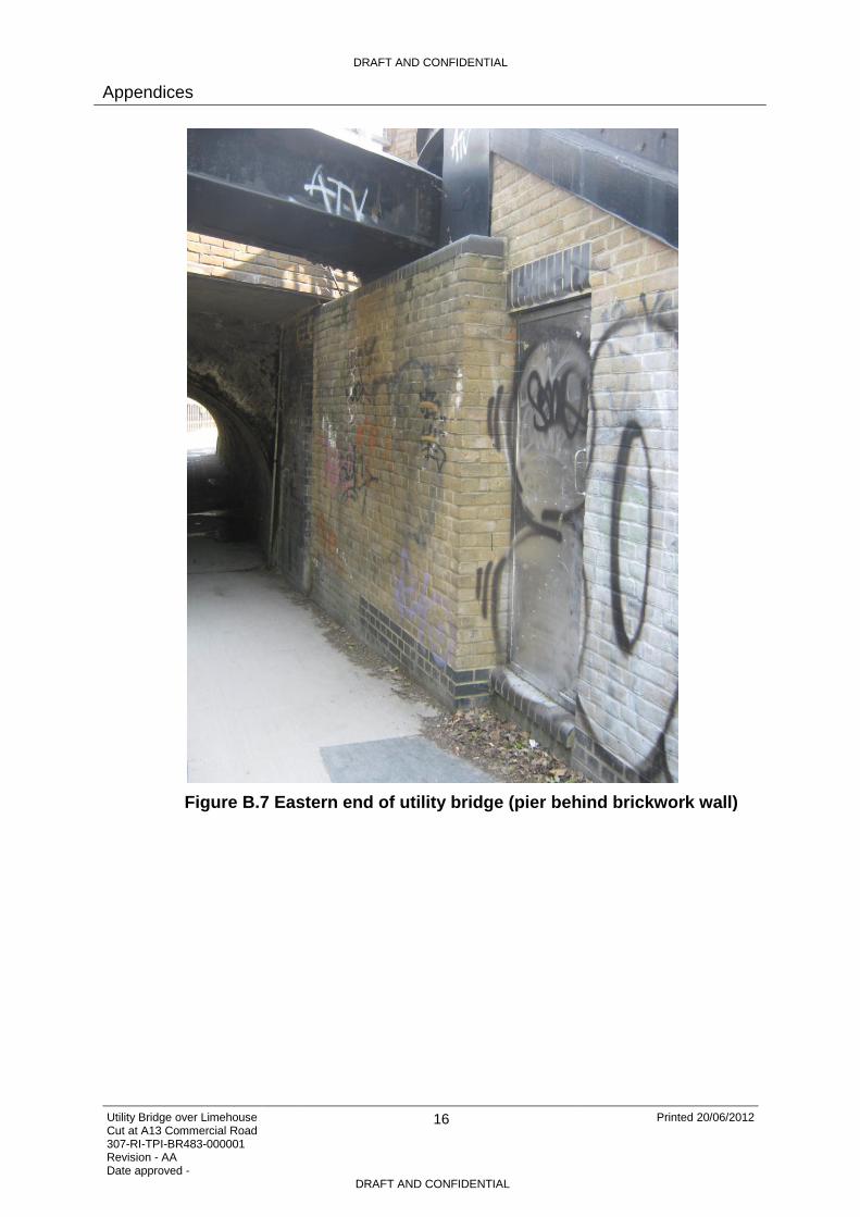
Figure B.7 Eastern end of utility bridge (pier behind brickwork wall) ........................ 16
Figure B.8 Cavity behind wall at eastern end of bridge, pier can just be seen angled behind the wall ................................................................................................. 17
Figure B.9 View from below of eastern end of utility bridge ...................................... 17
Figure B.10 Eastern end of utility bridge, bolted construction of I-section and plates visible ............................................................................................................... 18
Figure B.11 Bolted detail between bottom flange of longitudinal member and transverse plates .............................................................................................. 18
Figure B.12 View of underside of utility bridge (metal loop attached through hole in bottom flange) .................................................................................................. 19
Appendix A – List of Reviewed Information
A.1 Drawings
Department of Transport for London Regional Office: A13 Commercial Road London Britannia Bridge Partial Reconstruction: Volume 3: Contract Drawings
A.2 Reports
Water Regeneration: Jan 2001: Action Plan Limehouse Cut

DRAFT AND CONFIDENTIAL
Appendices
Utility Bridge over Limehouse Cut at A13 Commercial Road 307-RI-TPI-BR483-000001 Revision - AA Date approved -
11 Printed 20/06/2012
DRAFT AND CONFIDENTIAL
Appendix B – Photographic Records
Figure B.1 Utility Bridge over Limehouse Cut at A13 Commercial Road
Figure B.2 View from footpath to the east showing utility bridge and adjacent steps

DRAFT AND CONFIDENTIAL
Appendices
Utility Bridge over Limehouse Cut at A13 Commercial Road 307-RI-TPI-BR483-000001 Revision - AA Date approved -
12 Printed 20/06/2012
DRAFT AND CONFIDENTIAL
Figure B.3 Utility bridge looking towards western end

DRAFT AND CONFIDENTIAL
Appendices
Utility Bridge over Limehouse Cut at A13 Commercial Road 307-RI-TPI-BR483-000001 Revision - AA Date approved -
13 Printed 20/06/2012
DRAFT AND CONFIDENTIAL
Figure B.4 Western pier

DRAFT AND CONFIDENTIAL
Appendices
Utility Bridge over Limehouse Cut at A13 Commercial Road 307-RI-TPI-BR483-000001 Revision - AA Date approved -
14 Printed 20/06/2012
DRAFT AND CONFIDENTIAL
Figure B.5 View of top of utility bridge showing capping plate

DRAFT AND CONFIDENTIAL
Appendices
Utility Bridge over Limehouse Cut at A13 Commercial Road 307-RI-TPI-BR483-000001 Revision - AA Date approved -
15 Printed 20/06/2012
DRAFT AND CONFIDENTIAL
Figure B.6 Stair case from adjacent Britannia Road to the Limehouse Cut canal towpath
DRAFT AND CONFIDENTIAL
Appendices
Utility Bridge over Limehouse Cut at A13 Commercial Road 307-RI-TPI-BR483-000001 Revision - AA Date approved -
16 Printed 20/06/2012
DRAFT AND CONFIDENTIAL
Figure B.7 Eastern end of utility bridge (pier behind brickwork wall)

DRAFT AND CONFIDENTIAL
Appendices
Utility Bridge over Limehouse Cut at A13 Commercial Road 307-RI-TPI-BR483-000001 Revision - AA Date approved -
17 Printed 20/06/2012
DRAFT AND CONFIDENTIAL
Figure B.8 Cavity behind wall at eastern end of bridge, pier can just be seen angled behind the wall
Figure B.9 View from below of eastern end of utility bridge

DRAFT AND CONFIDENTIAL
Appendices
Utility Bridge over Limehouse Cut at A13 Commercial Road 307-RI-TPI-BR483-000001 Revision - AA Date approved -
18 Printed 20/06/2012
DRAFT AND CONFIDENTIAL
Figure B.10 Eastern end of utility bridge, bolted construction of I-section and plates visible
Figure B.11 Bolted detail between bottom flange of longitudinal member and transverse plates

DRAFT AND CONFIDENTIAL
Appendices
Utility Bridge over Limehouse Cut at A13 Commercial Road 307-RI-TPI-BR483-000001 Revision - AA Date approved -
19 Printed 20/06/2012
DRAFT AND CONFIDENTIAL
Figure B.12 View of underside of utility bridge (metal loop attached through hole in bottom flange)

Copyright notice Copyright © Thames Water Utilities Limited September 2013. All rights reserved. Any plans, drawings, designs and materials (materials) submitted by Thames Water Utilities Limited (Thames Water) as part of this application for Development Consent to the Planning Inspectorate are protected by copyright. You may only use this material (including making copies of it) in order to (a) inspect those plans, drawings, designs and materials at a more convenient time or place; or (b) to facilitate the exercise of a right to participate in the pre-examination or examination stages of the application which is available under the Planning Act 2008 and related regulations. Use for any other purpose is prohibited and further copies must not be made without the prior written consent of Thames Water. Thames Water Utilities LimitedClearwater Court, Vastern Road, Reading RG1 8DB The Thames Water logo and Thames Tideway Tunnel logo are © Thames Water Utilities Limited. All rights reserved.
Copyright notice Copyright © Thames Water Utilities Limited September 2013. All rights reserved. Any plans, drawings, designs and materials (materials) submitted by Thames Water Utilities Limited (Thames Water) as part of this application for Development Consent to the Planning Inspectorate are protected by copyright. You may only use this material (including making copies of it) in order to (a) inspect those plans, drawings, designs and materials at a more convenient time or place; or (b) to facilitate the exercise of a right to participate in the pre-examination or examination stages of the application which is available under the Planning Act 2008 and related regulations. Use for any other purpose is prohibited and further copies must not be made without the prior written consent of Thames Water. Thames Water Utilities LimitedClearwater Court, Vastern Road, Reading RG1 8DB The Thames Water logo and Thames Tideway Tunnel logo are © Thames Water Utilities Limited. All rights reserved.
10243-A4P-Copyright-imp-V01.pdf p1 12:03:39 September 21, 2013