Fast Thyristor/Diode and Thyristor/Thyristor (MAGN-A-PAK ...
1
Abstract—In the early days of power transmission problems
like voltage deviation during load changes and power transfer limitation were observed due to reactive power requirements of the transmission system. Today these problems have even higher impact on reliable and secure power supply in the world of globalisation and privatisation of electrical systems and energy transfer. Fast and highly reliable power electronic devices (thyristor valves) in Static Var Compensators (SVC) and HVDC applications proved their effectiveness in HV transmission systems to reduce energy transfer limitations. Influence of reactive power unbalances on the transmission systems and application of dynamic shunt compensation [1,2,3,4] ie SVC is discussed. Detailed information about the used components in SVCs is provided.
Index Terms—SVC, Reactive Power Compensation, FACTS
I. INTRODUCTION
OWER transmission based on three phase systems started in the late 19th century. The supply of electrical energy
developed from separated utilities to large interconnected systems. In former times distributed power generation supplied load centers within a limited supply area. These smaller systems were operated at lower voltage levels. Nowadays there is increased power exchange over larger distances at highest system voltages allowing reserve sharing and competition. Electrical energy shall be made available at most locations at minimum cost and at highest reliability. Following problems have been observed in three-phase-systems already at early times of power transfer: Voltage control at various load conditions Reactive power balance (voltage, transmission losses) Stability problems at energy transfer over long distances Increase of short circuit power in meshed systems Coupling of asynchronous systems Coupling of systems with different system frequencies
The last two problems can be solved using HVDC technology and the upper ones can be solved by proper use of reactive power compensation based on FACTS devices.
H. K Tyll is with Siemens AG, Erlangen, Germany High Voltage Division, PTD H16 Reactive Power Compensation and FACTS devices (e-mail: [email protected]).
II. EFFECTS OF REACTIVE POWER ON SYSTEM OPERATION AND
HOW IT CAN BE INFLUENCED
Reactive power is made available by components which are included in the system itself and by other components which are added to the system for balancing the system reactive power.
1) Types of Var Sources a) System components Inductances in electrical machines,
transmission lines, transformers, reactors Capacitances in transmission lines, cables
b) Compensation components Mechanically switched reactors and capacitors Synchronous condensers Thyristor controlled shunt and series compensation [1] Converter controlled shunt and series compensation
2) Influences in steady state system operation The influence on voltage from reactive power changes can be described simplified by the equation:
Psc
QV
∆=∆
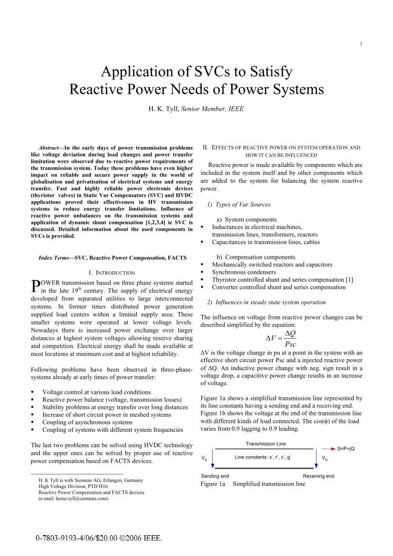
∆V is the voltage change in pu at a point in the system with an effective short circuit power Psc and a injected reactive power of ∆Q. An inductive power change with neg. sign result in a voltage drop, a capacitive power change results in an increase of voltage. Figure 1a shows a simplified transmission line represented by its line constants having a sending end and a receiving end. Figure 1b shows the voltage at the end of the transmission line with different kinds of load connected. The cos(φ) of the load varies from 0.9 lagging to 0.9 leading.
Figure 1a Simplified transmission line
Application of SVCs to Satisfy Reactive Power Needs of Power Systems
H. K. Tyll, Senior Member, IEEE
P
Line constants: x’, r’, c’, g’VS VR
S=P+jQTransmission Line
Sending end Receiving end
2
Figure 1 b Voltage at the end of the line at various power transfer levels P/PSIL and different load factors Using an appropriate compensation the voltage can be kept const for most load conditions. Above curve shows also that there are power transfer limits beyond no stable power transfer will exist. Above curves are based on a 200 km long transmission line. A safe distance to the "noses" of above curves should be used to avoid instability problems at transient system events. Figure 2 below shows a power plant which is connected to a larger system via a double line transmission system(upper part). The lower part of the figure shows simplified the voltages at the end of the transmission system for various load cases :
heavy load light load outage of one line during heavy load condition load rejection at the end of the line
According to the loading conditions voltage decreases and increases will occur with larger deviations at contingency conditions. An SVC will be typically designed in size to limit voltage deviations during normal load conditions and a good voltage profile is kept for this operation. At other contingency conditions larger voltage deviation will occur due to the sizing for normal conditions.
Figure 2 Voltages at the end of a transmission system under various operating conditions
3) Influences in transient system operation Figure 3 below shows the case of load rejection. The voltage rises rapidly in will be reduced by the voltage control means of the system ie voltage controllers in power plants. If a SVC is connected close the voltage will also rise rapidly but will be reduced in only a few cycles by the fast reaction of a SVC. The first peak cannot be influenced because the SVC control must first abserve the increase and can only react afterwards.
Figure 3 Action of a SVC on load rejection Figure 4 below shows a transmission system with strong active power oscillations after a severe line fault followed by fault clearing and switch off the faulted line.
Figure 4 Damping of power oscillations by SVC Without a SVC the oscillations continue at low damping for a long time. Using a SVC with voltage control already helps in damping of the oscillations and reducing the oscillation time. Using an SVC with a specific POD (power oscillation damping) control function will even damp out the oscillations quite faster and increase thus the margin in system stability. Providing damping to the system as the primary purpose during this critical system condition means that voltage control is no longer the main task and deviations from the anticipated system voltage is allowed.
III. SVC TECHNOLOGY
1) Tasks of SVCs
Load
SVC
230 kV - 300 km
V2 V1
Grid
without SVC
with SVC
1.2 1.1 1.0 0.9 0.8
a b c d
V2
V2N
a Heavy load b Light load c Outage of 1 line (at full load) d Load rejection at bus 2
System Conditions:
• Voltage control at steady-state and during transient system conditions

3
• Dynamic reactive power control for dynamic loads and Var management
• Damping of active power oscillations • Improvement of system stability • Voltage symmetrization
2) Basic branches of an SVC The dynamic controllable branches of an SVC are the TCR (Thyristor-controlled-reactor) and the TSC (Thyristor-switched-capacitor). Figure 5 below shows the basic circuit of a TCR.
Figure 5 Basic circuit of a TCR Antiparallel connected thyristors are series-connected with a reactor of high quality (very low losses). A sinusoidal voltage will result in a sinusoidal current when the thyristors are continuously conducting (α = 90°). By delaying the start of the current in each halve cycle by delaying the firing signal for the thyristors the current will start later and end earlier as seen in the lower part of figure 5 (example for α = 120°). Such a chopped current wave form contains fundamental and harmonic currents. The advantage of the TCR is the fine control of its installed reactive power from full load to zero and vice versa. The chopped current waves contain all harmonics of order 3, 5, 7, 9, 11, 13 etc within the single branch of a TCR. By connecting three TCR branches in delta all triplen harmonics will be suppressed. In reality the line current does not only contain the so-called characteristic six pulse harmonic currents but also non-characteristic currents which arise mainly due to negative sequence voltage content in the system voltage (all triplen harmonics) and even harmonics which result from tolerances on the firing pulses in positive and negative direction.
The figure 6 below shows a set of harmonic currents based on 1% neg. seq. voltage content and a firing angle unsymmetry of
± 0.1°. Figure 6 Characteristic and noncharacteristic harmonic currents The x-axis shows the harmonic number, the y-axis shows the amount of harmonic content in % related to the 90°-current of the TCR. Figure 7 below shows the basic circuit of a TSC.
Figure 7 Basic circuit of a TSC Here the reactor of the TCR is replaced by a capacitor. At full conduction of the valves the synusoidol voltage Vsys results in a 90° phase shifted capacitive current I. If the thyristors are no longer switched by firing pulses the current I through the capacitor stops and the voltage Vc of the capacitor does no longer follow the system voltage Vsys and remains at the voltage at the time of blocking. The best time to reconnect the capacitor is at the point of time where system voltage and the capacitor voltage are equal. At that point only minimum transients due to switching-on will occur. At all other times
I
a = 90°
a = 120°
Vsys
I120
Vsys
I90
I
a = 90°
a = 120°
Vsys
I120
Vsys
I90
Even Harmonics due to Tolerances
Characteristic Harmonics of TCROdd Harmonics due to Negative Sequence
0.01
0.1
1
10
1 3 5 7 9 11 13 15 17 19 21 23 25
Even Harmonics due to Tolerances
Characteristic Harmonics of TCROdd Harmonics due to Negative SequenceEven Harmonics due to Tolerances
Characteristic Harmonics of TCROdd Harmonics due to Negative Sequence
0.01
0.1
1
10
1 3 5 7 9 11 13 15 17 19 21 23 25
Vsys
I
Vsys
Vc
VcI
blocking switch-in
Vsys
I
Vsys
Vc
VcI
blocking switch-in
more or less strong transients will occur and therefore only step-wise control of the TSC is allowed.

4 3) Configurations of SVCs Using TCR-, TSC- and Filter (or so-called fixed connected: FC) branches result in possible configurations as shown below:
Figure 8a Six pulse arrangements Figure 8b Twelve pulse arrangements Figure 8a shows a combination of TCR and FC without using a TSC branch. The TCR branch must be designed to compensate the FC branch and in addition to absorb reactive power from the system if required. In the arrangement TCR, TSC and FC the capacitive installed power is sub divided in a TSC branch and the FC branch. The FC branch typically will be arranged as two filters tuned to 5th and 7th harmonic. The inductive operating point will now be reached together with a smaller rated FC branch . The TCR branch is therefore designed on a lower power level. The power of the TCR must
be slightly larger than the TSC branch to avoid hunting at switch-over points. Figure 8c Direct connection Direct connection of TCR and Filter branches may also be used for system voltages below 36 kV. 4) V / I Characteristics of SVCs All SVCs based on the described configurations have a V/I characteristic similar to figure 9.
Figure 9 Typical V/I Characteristic as seen from the high voltage system The V/I characteristic is limited by a straight line on the left side according to the installed capacitive power of the SVC. The straight line on the right side is the limitation according to the required inductive design point. At low voltages the SVC output follows the capacitive limitation, at higher voltages the SVC output follows the inductive limitation. The SVC will work on a controlled basis in a typical system operating voltage range between reference voltages of 0.95 to 1.05 pu.
TCR, FC TSR, TSCTCR, TSC, FC
HV
LV1
LTCR12
TCR 1
LTCR12
Filter 1
LF1
CF1
13 kV
LTCR22
TCR 2
LTCR22
Filter 2
LF2
CF2
LV2 13 kV
LTCR2
TCR
LTCR2
Filter 3
LF3
CF3
V <36 kV
Filter 1
LF1
CF1
Filter 2
LF2
CF2
Restrictionto 150 MVar
Ind. RangeCap. Range
VHV
Minimumoperatingvoltage
1.3
pu
1.1
1.0
0.5
2 %
5 %
10 %
10 %
5 %
2 %
VBase = 400 kVIBase = 100 MVA
Continuous Operation
Restricted Operation
Inductivedesign point75 MVarat 1.02 pu
Capacitivedesign point-150 MVarat 0.95 pu
-2.0 -1.5 -1.0 -0.5 0.0 0.5 1.0 IHV [pu]

5
Figure 10 Typical V/I Characteristic as seen from the low voltage SVC bus At capacitive operation the secondary side voltage increases due to the leakage inductance of the transformer winding. At this operating points any saturation of the transformer must be avoided. Contrary to typical system transformers this results in magnetization knee point of 1.2 to 1.4 pu depending on specified operating requirements. 5) Design considerations for SVC main components [5] The tables below summarizes main tasks of the various components on the left side and show also some design aspects on the right side.
The decision of three phase or single phase transformers are typically based on spare part considerations ie availability constraints. Environmental conditions like noise requirements sometimes lead to noise shielding.
Figure11 Three phase transformer enclosed by a brick wall building for noise reduction
Figure 12 Single phase transformers separated by fire protection walls
The decision for single phase reactors (TCR) is based typically on spare part requirements.
Figure 13 Typical arrangement of double-stacked TCR reactors
Figure 13 Capacitor bank (externally fused)
Restrictionto 150 MVar
Capacitivedesign point-150 MVarat 0.95 pu
Ind. RangeCap. Range
Minimumoperatingvoltage
1.3
pu
1.1
1.0
0.5
2 %5 %
10 %
10 %
5 %
2 %
VBase = 14 kVIBase = 100 MVA
Continuous OperationRestricted Operation
VLV
Inductivedesign point75 MVarat 1.02 pu
-2.0 -1.5 -1.0 -0.5 0.0 0.5 1.0 ILV [pu]
Restrictionto 150 MVar
Capacitivedesign point-150 MVarat 0.95 pu
Ind. RangeCap. Range
Minimumoperatingvoltage
1.3
pu
1.1
1.0
0.5
2 %5 %
10 %
10 %
5 %
2 %
VBase = 14 kVIBase = 100 MVA
Continuous OperationRestricted Operation
VLV
Inductivedesign point75 MVarat 1.02 pu
-2.0 -1.5 -1.0 -0.5 0.0 0.5 1.0 ILV [pu] Reactors • Single phase air core reactors
in different 3phase arrangement • Iron core reactors with air gaps
as three phase units
• Continuous operating range • Short time overload • Harmonic stresses • Spare parts • Transportation limitations • Environmental conditions
Transformer • Matching to the system • Single or three phase units
or 3-winding transformers • short circuit impedance
• Continuous operating range • Short time overload • Harmonic stresses • Spare parts • Transportation limitations • Environmental conditions
Capacitors • Series and parallel connection of
small units • Outdoor / indoor installation • Internal / external fusing
• Continuous operating range • Overload requirements • Harmonic stresses • Protection systems

6
Figure 14 (below) Thyristor valve phase modul based on 8 kV, Light triggered thyristors, integrated overvoltage protection on silicon wafer
Figure 15 Simplified voltage control block diagram In most cases SVCs are used for system voltage control ie fast capacitive support in critical system conditions. In some conditions additional control functions may be included for better system control:
Power oscillation damping control to improve system stability
Reactive power control direct compensation of large industrial plants or in conjunction with Var management schemes
Degraded operating control modes to increases the total operating flexibility of the SVC
Automatic gain adjustment to provide in all system situations best control response.
IV. SUMMARY
Major surplus or lack of reactive power in transmission systems can result in severe voltage stability and/or power transfer problems. Dynamic shunt compensation devices like the SVC help to overcome these problems also during critical system conditions. More than 80 % of these dynamic Vars are using highly reliable thyristor based configurations. It is most important to specify [6] the required operating characteristics correct together with system conditions on harmonics and fault level to be sure that the devices will function as expected.
V. REFERENCES
Papers Presented at Conferences (Unpublished): [1] H. K. Tyll, "FACTS Technology for Reactive Power Compensation and
System Control", presented at IEEE T&D Conference Sao Paulo, 2004
Books: [2] Y.H. Song and A.T. Johns, "Flexible ac transmission systems (FACTS)",
IEE 1999, ISBN 0-85296-771 3 [3] N.G. Hingorani and L. Gyugyi, "Understanding FACTS", IEEE PRESS,
ISBN 0-7803-1196-6 [4] T.J.E. Miller, Reactive Power Control in Electric Systems, John Wiley
&Sons, 1982
Technical Reports: [5] H.K.Tyll et all, "Design considerations for the Eddy County Static Var
Compensator", 93-SM-450-7 PWRD
Standards: [6] IEEE Functional Specification sand Application of Static Var
Compensators, IEEE Standard 1031-2002
VI. BIOGRAPHY
Heinz Karl Tyll (M’88, SM’93) was born in Hof, Federal Republic of Germany on May 15, 1947. In 1968 he graduated in Electrical Engineering from Coburg Polytechnikum. In 1974 he received the Diplom degree from the Technical University of Berlin. After joining Siemens AG, he worked in their High Voltage Transmission Engineering Department since 1975 in the field of network and SVC system analysis with transient network analyzer and digital programs. In 1988 he transferred to the System Engineering Group of the HVDC and SVC Sales Department. Since 1996 he
is responsible for Basic Design of SVC, SC and FACTS applications. He contributed to CIGRE WG 38 TFs and to relevant IEEE WG. He is member of IEEE and VDE.
Valves • TCR, TSR or TSC valves • Optimum use of thyristor ratings
• Continuous operating range • Overload requirements • Stresses during system faults and
false firing events • Insulation co-ordination
Control and protection • ON / OFF control • Local / remote control • Control characteristics
− Voltage control − Reactive power control − Power oscillation damping − Symmetrization
• Use of conventional protection
• Type of control • Control requirements • Harmonic instability • System characteristics
− Network impedance − System unbalances
• Component design ratings
Power SystemVT
Vact
Vref
∆VSystemVoltage
Evaluation
TCR TSCFC BSVC
VoltageController
TSCController
TCR/TSRController
LV
HVPower System
VT
Vact
Vref
∆VSystemVoltage
Evaluation
TCR TSCFC BSVC
VoltageController
TSCController
TCR/TSRController
LV
HV


![Rail Power Conditioner Based on Indirect AC/DC/AC … · speed and high power railways systems, ... or static synchronous compensators (STATCOMs) [5]. The main disadvantage of SVCs](https://static.fdocuments.net/doc/165x107/5ae271257f8b9a5d648cb0f1/rail-power-conditioner-based-on-indirect-acdcac-and-high-power-railways-systems.jpg)