
Application of High Strength Microalloyed Steel in a New ...
8
Application of High Strength Microalloyed Steel in a New Automotive Crankshaft Young Sang Ko, Jin Woo Park, Hyounsoo Park, Jong Dae Lim Hyundai and Kia Motor Company Research and Development Division 722-1, Changduk Whasung, Kyunggi 445-850 Korea Tel: 82-31-368-7355 Fax: 82-31-368-7355 E-mail: [email protected], [email protected] David K. Matlock Advanced Steel Processing and Products Research Center Colorado School of Mines Golden, CO 80401 Tel: 303-273-3025 Fax: 303-273-3016 E-mail: [email protected] Key Words: microalloyed steel, forging, crankshaft INTRODUCTION Applications of steels for new forged automotive components require a complete understanding of material properties and design requirements. Today there are many potential combinations of steel bar compositions and surface hardening methods that can be employed. Generally plain carbon steels, alloy steels, and microalloyed steels are used for forged bar applications and nitriding, induction hardening, or fillet rolling are applied to selected highly-stressed areas to produced optimum performance. At the preliminary stage in the design of a new model several factors must be considered. Cost, infrastructure requirements, and lead time are considered together to ensure proper selection of material alloy and hardening method. Currently many crankshaft forging companies have eliminated quenching and tempering (Q&T) heat-treatment facilities from their shops, and thus in the production of crankshafts it is not easy to apply alloy steels that require Q&T processing. The use of microalloyed steels in crankshafts have been shown to be a viable alternative to Q&T steels, particularly in engines that require significant improvements in performance [1]. High strength of microalloyed bar steels develop desired properties through additions of microalloying elements such as V, Ti, Nb [2] in conjunction with control of processing which may include direct cooling. For specific applications, the use of microalloy additions provides the optimum method to tailor the material properties for a specific crankshaft application. In this paper, the development and choice of steel for a new crankshaft application are used to illustrate the stages in the process of selecting materials for new applications. The major processes required in the production of new prototype crankshafts were investigated and highlights of the results demonstrate a methodology for material selection. The goal of this study is to optimize selection of the appropriate microalloyed bar steel that simultaneously satisfies strength requirements to meet the criteria in specific areas listed below for high performance as well as achieves the required properties, i.e. hot formability and machinability, required to successfully and economically produce the parts. Specific mechanical properties that must be met include high fatigue strength in fillets and high surface hardnesses on journal surfaces to prevent abrasive wear at high contact forces. For reference, Figure 1 summarizes the steps involved in evaluating materials for new crankshaft applications. 3 2006 New Developments in Long and Forged Products Proceedings
Transcript of Application of High Strength Microalloyed Steel in a New ...

Application of High Strength Microalloyed Steel in a New Automotive Crankshaft
Young Sang Ko, Jin Woo Park, Hyounsoo Park, Jong Dae Lim Hyundai and Kia Motor Company
Research and Development Division 722-1, Changduk
Whasung, Kyunggi 445-850 Korea
Tel: 82-31-368-7355 Fax: 82-31-368-7355
E-mail: [email protected], [email protected]
David K. Matlock Advanced Steel Processing and Products Research Center
Colorado School of Mines Golden, CO 80401 Tel: 303-273-3025 Fax: 303-273-3016
E-mail: [email protected]
Key Words: microalloyed steel, forging, crankshaft
INTRODUCTION Applications of steels for new forged automotive components require a complete understanding of material properties and design requirements. Today there are many potential combinations of steel bar compositions and surface hardening methods that can be employed. Generally plain carbon steels, alloy steels, and microalloyed steels are used for forged bar applications and nitriding, induction hardening, or fillet rolling are applied to selected highly-stressed areas to produced optimum performance. At the preliminary stage in the design of a new model several factors must be considered. Cost, infrastructure requirements, and lead time are considered together to ensure proper selection of material alloy and hardening method. Currently many crankshaft forging companies have eliminated quenching and tempering (Q&T) heat-treatment facilities from their shops, and thus in the production of crankshafts it is not easy to apply alloy steels that require Q&T processing. The use of microalloyed steels in crankshafts have been shown to be a viable alternative to Q&T steels, particularly in engines that require significant improvements in performance [1]. High strength of microalloyed bar steels develop desired properties through additions of microalloying elements such as V, Ti, Nb [2] in conjunction with control of processing which may include direct cooling. For specific applications, the use of microalloy additions provides the optimum method to tailor the material properties for a specific crankshaft application. In this paper, the development and choice of steel for a new crankshaft application are used to illustrate the stages in the process of selecting materials for new applications. The major processes required in the production of new prototype crankshafts were investigated and highlights of the results demonstrate a methodology for material selection. The goal of this study is to optimize selection of the appropriate microalloyed bar steel that simultaneously satisfies strength requirements to meet the criteria in specific areas listed below for high performance as well as achieves the required properties, i.e. hot formability and machinability, required to successfully and economically produce the parts. Specific mechanical properties that must be met include high fatigue strength in fillets and high surface hardnesses on journal surfaces to prevent abrasive wear at high contact forces. For reference, Figure 1 summarizes the steps involved in evaluating materials for new crankshaft applications.
32006 New Developments in Long and Forged Products Proceedings

Concept Design requirement
Selection Alloy design and strengthening
Making Bar steel Evaluate the properties
Making forged part Evaluate the properties
Making machined part
Simulation of forging Optimize the process parameters
New crankshaft
Figure 1 Flow chart illustrating the multiple steps required in the production of a new prototype crankshaft.
EXPERIMENTAL PROCEDURES Table I summarizes the compositions of the four steels chosen for this study. Steel T1 is an alloy steel, typically processed by Q&T processing, and is used as a reference. Steel T2 is a conventional medium carbon microalloyed steel, and steels T3 and T4 are microalloyed steels with higher Si, Mn, and V contents in comparison to T2. The higher alloy additions in T3 and T4 were designed to increase strength in comparison to the properties of steel T2. The limited strength of the conventional microalloyed steel T2 makes it unsuitable for high performance components. The steel properties were evaluated utilizing standard metallographic, mechanical testing, and machinability tests.
Table I Chemical composition of the steels for crankshafts (wt. pct.)
Steel C Si Mn S Cr Mo V Al S N (ppm)
T1 0.43 0.24 0.85 0.01 1.00 0.16 0.015 0.030 max 60-100
T2 0.45 0.20 1.10 0.06 0.16 ≤0.05 0.10 ≤0.02 0.04-0.07 60-100
T3 0.39 0.67 1.38 0.05 0.12 ≤0.05 0.14 ≤0.02 0.04-0.07 80-120
T4 0.43 0.62 1.41 0.05 0.15 ≤0.05 0.25 ≤0.02 0.04-0.07 80-120
RESULTS AND DISCUSSIONS Microstructure Evaluation of Bar Steels The microalloyed steels exhibited ferrite-pearlite microstructures as illustrated in Figure 2 which shows light optical micrographs for steels T3 and T4 as viewed on metallographic samples removed from as-forged crankshafts. The prior austenite grain size (AGS) of steel T3 is 105 µm which corresponds to an ASTM grain size number 3, and the AGS of steel T4 is finer with an ASTM grain size number of 4~5. The finer grain size is due in part to the combination of Al and N in the steels. Strength in these steels is derived from a combination of grain size control, pearlite volume fraction control, solid solution strengthening, and precipitation hardening [3].
4 2006 New Developments in Long and Forged Products Proceedings

100�
100�
(a) T3 (b) T4
Figure 2 Light optical micrographs of samples removed from forged crankshafts: (a) steel T3 and (b) steel T4. (2 % Nital etch) Mechanical Properties of Forged Crankshafts The mechanical properties of the forged crankshafts evaluated in this study are demonstrated by using tensile, fatigue, and full component tests. Table II shows the mechanical test results from tensile and hardness testing with the test specimen coupons removed from as-forged crankshafts. It should be noted that the strengths of T3 and T4 were 922 MPa and 1008 MPa respectively which are similar or higher than for alloy steel T1. Due to the higher Si and Mn contents, these strengths are consistent with and slightly higher than predicted from extrapolation of the results of Sawada et al. [4] that show the combined effects of carbon content and microalloy additions on the mechanical properties of forging steels.
Table II Mechanical properties of forged crankshaft
Steels UTS (MPa) EL (%) RA (%) Hardness (HB)
T1 977 12 37 287 T2 882 12 35 231 T3 922 12 26 280 T4 1008 11 21 312
Figure 3 shows the results of rotating bending fatigue tests of samples machined from forged crankshafts of steels T1, T3 and T4. The fatigue strength of the T1 alloy steel is approximately 400 MPa and that of steel T3 is 390 MPa. In comparison, the fatigue strength of steel T4 is higher at approximately 448 MPa. An analysis of the data in Table 2 and Figure 3 shows that based on a consideration of mechanical properties, microalloyed steel T4 can replace the Q&T alloyed steel without any loss in strength. The results also show good agreement with the general ratio of fatigue strength to UTS. Thus, microalloyed steel T4 was recommended to obtain the necessary high strength in the finished crankshaft.
Number of Cycles
Rot
atin
g Be
ndin
g S
tress
(MPa
)
steels.
Figure 3 Rotating bending fatigue properties of experimental Forging Process Simulation In the production of crankshafts, one of the most difficult components to forge is the V-shape crankshaft. Difficulties in forging arise because the V-type engine crankshaft is not symmetric and possesses unbalanced shapes as illustrated in the images presented in Figure 4. The results in Figure 4 were obtained from a finite element (FE) model applied to the crankshaft and used to predict the strain and strain rate histories experienced by each point in the part. In this study, the FE model was used to eliminate costly trial and
52006 New Developments in Long and Forged Products Proceedings

error work often employed to produce proper dies for V-shaped crankshafts. Normally a V-shape crankshaft has two big weight balances at the front and rear side and these locations are weak points during hot forging. Hot forming simulation can be used to evaluate potential problems with the die and work piece during forging. To illustrate results obtained from the FE model, Figure 5 shows point tracking surveys at the blocking stage. At each point indicated in Figure 5a, the strain history and strain rate history were monitored as summarized in Figures 5b and 5c, respectively. These data were coupled with the high temperature flow curves measured with a Gleeble® and selected curves are shown in Figure 6. From the characteristics of the strain behavior at each stage in the operation, the die design was optimized by minimizing the development of excessive strain at any specific location during forging. These results were used to successfully guide crankshaft prototyping by tracking strains at specific points and this information was used to avoid the development of any forging defects. The FE model successfully predicted the material response during forging.
Busting Blocking Rolling
Figure 4 Solid model predictions obtained from the finite element model for forging of V-shape crankshafts. Images illustrate the complex non-uniformity associated with the unbalanced crankshaft geometry.
(a)
0.0
0.2
0.4
0.6
0.8
1.0
1.2
1.4
0 1 2 3 4 5 6 7
Time (sec)
Effe
ctiv
e st
rain
1
2
3
4
5
0
2
4
6
8
10
12
14
16
18
0 1 2 3 4 5
Time (sec)
Stra
in ra
te (p
er s
ec)
1
2
3
4
5
(b) (c)
Figure 5 Finite element model predictions of the point tracking survey at the blocking stage: (a) cut through solid model showing
locations for predictions of (b) strain versus time data and (c) strain rate versus time.
6 2006 New Developments in Long and Forged Products Proceedings
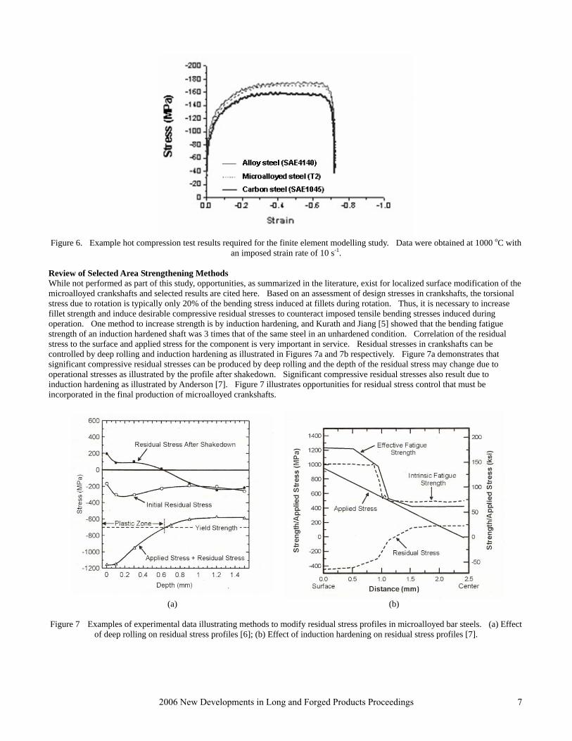
Figure 6. Example hot compression test results required for the finite element modelling study. Data were obtained at 1000 oC with
an imposed strain rate of 10 s-1. Review of Selected Area Strengthening Methods While not performed as part of this study, opportunities, as summarized in the literature, exist for localized surface modification of the microalloyed crankshafts and selected results are cited here. Based on an assessment of design stresses in crankshafts, the torsional stress due to rotation is typically only 20% of the bending stress induced at fillets during rotation. Thus, it is necessary to increase fillet strength and induce desirable compressive residual stresses to counteract imposed tensile bending stresses induced during operation. One method to increase strength is by induction hardening, and Kurath and Jiang [5] showed that the bending fatigue strength of an induction hardened shaft was 3 times that of the same steel in an unhardened condition. Correlation of the residual stress to the surface and applied stress for the component is very important in service. Residual stresses in crankshafts can be controlled by deep rolling and induction hardening as illustrated in Figures 7a and 7b respectively. Figure 7a demonstrates that significant compressive residual stresses can be produced by deep rolling and the depth of the residual stress may change due to operational stresses as illustrated by the profile after shakedown. Significant compressive residual stresses also result due to induction hardening as illustrated by Anderson [7]. Figure 7 illustrates opportunities for residual stress control that must be incorporated in the final production of microalloyed crankshafts.
(a) (b)
Figure 7 Examples of experimental data illustrating methods to modify residual stress profiles in microalloyed bar steels. (a) Effect
of deep rolling on residual stress profiles [6]; (b) Effect of induction hardening on residual stress profiles [7].
72006 New Developments in Long and Forged Products Proceedings
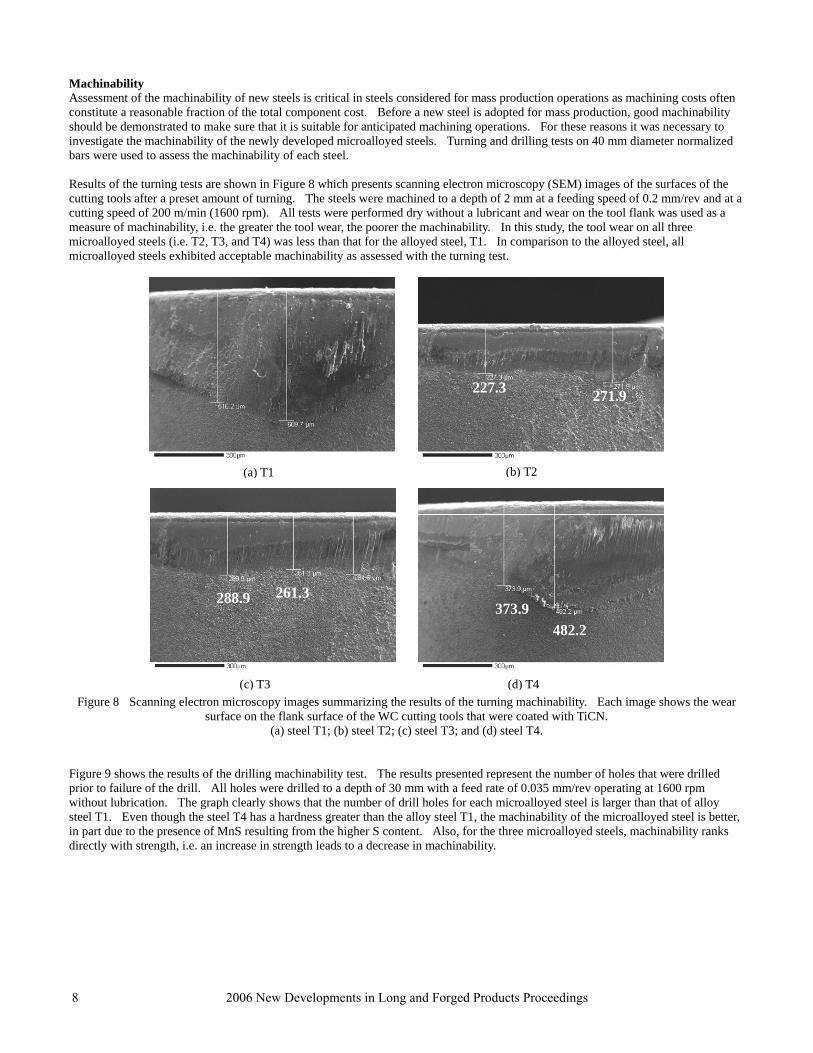
Machinability Assessment of the machinability of new steels is critical in steels considered for mass production operations as machining costs often constitute a reasonable fraction of the total component cost. Before a new steel is adopted for mass production, good machinability should be demonstrated to make sure that it is suitable for anticipated machining operations. For these reasons it was necessary to investigate the machinability of the newly developed microalloyed steels. Turning and drilling tests on 40 mm diameter normalized bars were used to assess the machinability of each steel. Results of the turning tests are shown in Figure 8 which presents scanning electron microscopy (SEM) images of the surfaces of the cutting tools after a preset amount of turning. The steels were machined to a depth of 2 mm at a feeding speed of 0.2 mm/rev and at a cutting speed of 200 m/min (1600 rpm). All tests were performed dry without a lubricant and wear on the tool flank was used as a measure of machinability, i.e. the greater the tool wear, the poorer the machinability. In this study, the tool wear on all three microalloyed steels (i.e. T2, T3, and T4) was less than that for the alloyed steel, T1. In comparison to the alloyed steel, all microalloyed steels exhibited acceptable machinability as assessed with the turning test.
373.9482.2
T
261.3288.9
271.9227.3
( T1 (bT1
) T3 Figure 8 Scanning electron m copy images summarizing the results of the turning inability. Each image shows the wear
surface on the flank surface of the WC cutting tools that were
T3 (d(d(d
(a) steel T1; (b) steel T2; (c) steel T3; and (d) stee Figure 9 shows the results of the drilling machinability test. The results presented represprior to failure of the drill. All holes were drilled to a depth of 30 mm with a feed rate ofwithout lubrication. The graph clearly shows that the number of drill holes for each micrsteel T1. Even though the steel T4 has a hardness greater than the alloy steel T1, the macin part due to the presence of MnS resulting from the higher S content. Also, for the thredirectly with strength, i.e. an increase in strength leads to a decrease in machinability.
8 2006 New Developments in Long and Forged Products
T(d)mach) T4) T4) T4
Tb)) T2
(a)(a)(cicros
(c)
coated with TiCN. l T4.
ent the number of holes that were drilled 0.035 mm/rev operating at 1600 rpm oalloyed steel is larger than that of alloy hinability of the microalloyed steel is better, e microalloyed steels, machinability ranks
Proceedings
0
10
20
30
40
50
60
70
80
90
100
T1 T2 T3 T4
Tested steels
Num
ber o
f hol
es
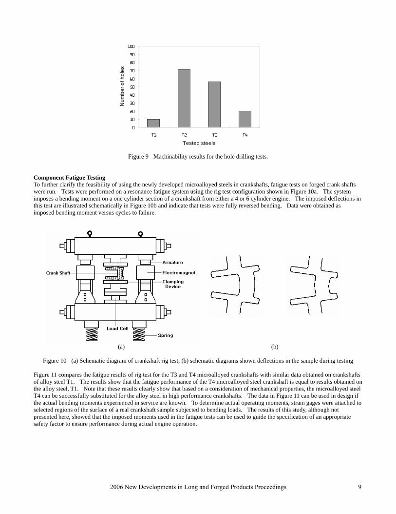
Figure 9 Machinability results for the hole drilling tests.
Component Fatigue Testing To further clarify the feasibility of using the newly developed microalloyed steels in crankshafts, fatigue tests on forged crank shafts were run. Tests were performed on a resonance fatigue system using the rig test configuration shown in Figure 10a. The system imposes a bending moment on a one cylinder section of a crankshaft from either a 4 or 6 cylinder engine. The imposed deflections in this test are illustrated schematically in Figure 10b and indicate that tests were fully reversed bending. Data were obtained as imposed bending moment versus cycles to failure.
(a) (b)
Figure 10 (a) Schematic diagram of crankshaft rig test; (b) schematic diagrams shown deflections in the sample during testing Figure 11 compares the fatigue results of rig test for the T3 and T4 microalloyed crankshafts with similar data obtained on crankshafts of alloy steel T1. The results show that the fatigue performance of the T4 microalloyed steel crankshaft is equal to results obtained on the alloy steel, T1. Note that these results clearly show that based on a consideration of mechanical properties, the microalloyed steel T4 can be successfully substituted for the alloy steel in high performance crankshafts. The data in Figure 11 can be used in design if the actual bending moments experienced in service are known. To determine actual operating moments, strain gages were attached to selected regions of the surface of a real crankshaft sample subjected to bending loads. The results of this study, although not presented here, showed that the imposed moments used in the fatigue tests can be used to guide the specification of an appropriate safety factor to ensure performance during actual engine operation.
92006 New Developments in Long and Forged Products Proceedings

Ben
ding
Fat
igue
Mom
ent (
Nm
)
Number of Cycles
Figure 11 Results of rig test crankshaft fatigue tests.
SUMMARY
This paper has highlighted the results of an extensive study to certify the use of microalloyed steels in crankshafts for high performance engines. It was shown that an optimal alloy design for a new microalloyed steel was proposed to achieve excellent mechanical properties and to potentially replace an alloy steel. The desirable performance of the microalloyed steels resulted from control of the volume fraction of pearlite through proper choice of carbon, grain size refinement, and precipitation hardening due the presence of V. These steels exhibited machinability, due to the presence of MnS, that is superior to the alloy steel used as a reference. Finally, it was concluded that the microalloyed steels can replace the alloy steel with equal or improved fatigue performance, but at a reduced cost that results from eliminating expensive alloying elements and Q&T heat treating cycles and by producing a material with improved machinability.
ACKNOWLEDGEMENTS The authors express their sincere appreciation to Mr. Sung-Do Wang and his colleagues of Seah Besteel Co. for their experimental support in alloy development and evaluation. One author (DKM) acknowledges the support of the sponsors of the Advanced Steel Processing and Products Research Center, an Industry-University Cooperative Research Center at the Colorado School of Mines.
REFERENCES 1. “The World’s Top 10 Best Engines Use Steel,” American Iron and Steel Institute, Southfield, MI (2004),
<http://www.autosteel.org>. 2. M.Cristinace and P.E. Reynolds, ”The Current Status of the Development and Use of Air Cooled Steels for the Automotive
Industry”, in Fundamentals and Applications of Microalloying Forging Steels, ed. by C.J. Van Tyne, G. Krauss, and D.K. Matlock, TMS-AIME, Warrendale, PA, 1996, pp. 29-43.
3. D.K. Matlock, G. Krauss, and J.G. Speer, “New Microalloyed Steel Applications for the Automotive Sector,” Materials Science Forum, Vols. 500-501, 2005, pp. 87-96.
4. Y. Sawada, R.P. Foley, S.W. Thompson, and G. Krauss, “Microstructure-Property Relationships in Plain-carbon, and V and V+Nb Microalloyed Medium-carbon Steels,” Proceedings of the 35th Mechanical Working and Steel Processing Conference, Vol. XXXI, ISS-AIME, Warrendale, PA (1994), pp. 263-286.
5. P. Kurath and Y. Jiang, “Analysis of residual Stresses and Cyclic Deformation for Induction Hardened Component”, SAEpublication No. 950707, Warrendale, Pa, 1995.
5, pp. 384-389 6. F. Galzy, H.Michaud and J.M. Sprauel, “Approach of Residual Stress Generated by Deep Rolling Application to the
Reinforcement of the Fatigue Resistance of Crankshafts,” Materials Science Forum, Vols. 490-491, 2007. P.I. Anderson, “Induction Hardening Response of Ferrite and Pearlite Banded Steel,” MS Thesis, Colorado School of Mines,
Golden, Colorado, 2005.
10 2006 New Developments in Long and Forged Products Proceedings


