Application of Crystal Plasticity to Fatigue Damage Modeling for...
25
Application of Crystal Plasticity to Fatigue Damage Modeling for Al 7075-T651 David Littlewood and Antoinette Maniatty [email protected] Mechanical, Aerospace, and Nuclear Engineering Rensselaer Polytechnic Institute Collaborators: Tony Ingraffea (Cornell), Tony Rollett (Carnegie Mellon), Hasso Weiland (Alcoa), Mark Horstemeyer (Mississippi State), Bob Wei and Gary Harlow (Lehigh) Sponsor: DARPA SIPS program (Northrop-Grumman) WCCM 2006 – slide 1/19
Transcript of Application of Crystal Plasticity to Fatigue Damage Modeling for...
Application of Crystal Plasticity to FatigueDamage Modeling for Al 7075-T651
David Littlewood and Antoinette [email protected]
Mechanical, Aerospace, and Nuclear Engineering
Rensselaer Polytechnic Institute
Collaborators: Tony Ingraffea (Cornell), Tony Rollett (Carnegie Mellon),
Hasso Weiland (Alcoa), Mark Horstemeyer (Mississippi State),
Bob Wei and Gary Harlow (Lehigh)
Sponsor: DARPA SIPS program (Northrop-Grumman)
WCCM 2006 – slide 1/19

Outline
F Motivation
F Methodology
F Constitutive model
F Finite element formulation
F Metrics for damage accumulation
F Implementation
F Results
F Calibration results
F Example: 45-grain polycrystal
F Future work
WCCM 2006 – slide 2/19
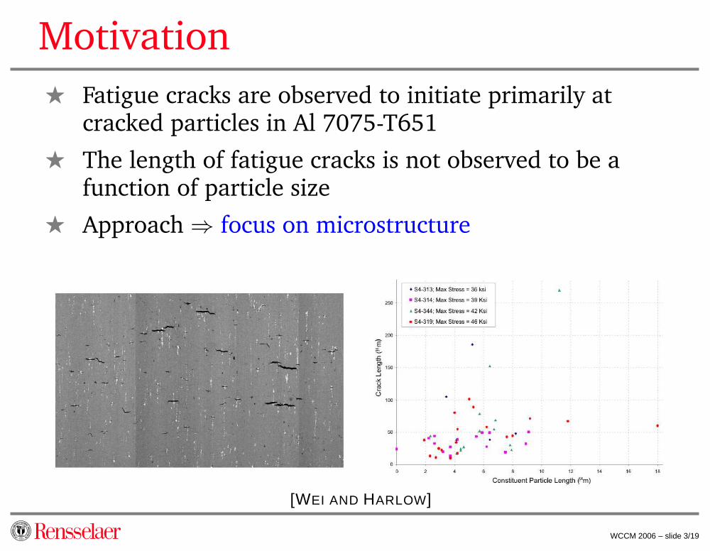
Motivation
F Fatigue cracks are observed to initiate primarily atcracked particles in Al 7075-T651
F The length of fatigue cracks is not observed to be afunction of particle size
F Approach ⇒ focus on microstructure
[WEI AND HARLOW]
WCCM 2006 – slide 3/19

Multiscale Nature of Problem
[WEI AND HARLOW, WEILAND, WIEZOREK]
WCCM 2006 – slide 4/19

Collaborative Approach
Orowan Looping
Cornell, RPI
RPI
ConstitutiveCrystal
Model
UnderlyingPhenomena
ExperimentalObservations
Lehigh, AlcoaCMU, MSU, NG
PolycrystalModel
WCCM 2006 – slide 5/19

Methodology
Constitutive Model
Deformation gradient F = eF pF
Green strain tensor eE = 12
(eFT eF − I
)
Hyperelastic potential ψ = 12
eE : C : e
E
Second Piola-Kirchoff stress S = C : eE
Anisotropic elasticity Cijkn = Cjikn = Cijnk = Cknij
[Kocks (1966), Hart (1972), Schmitt, Lipinski,
Berveiller (1997), Han, Wagoner and Barlat (2004)]
WCCM 2006 – slide 6/19

Methodology
Slip Model
Plastic velocity gradient pL =∑12
α=1 γα Pα
Schmid tensor Pα = sα⊗ mα
Slip rate γα = γoτα
gα
∣∣∣ τα
gα
∣∣∣1
m−1
Hardness evolution gα = Go
(go−gα
gs−go
)Hαβ
Projection factor Hαβ =∑
β 2∣∣∣Sα
ij Sβij
∣∣∣∣∣γβ
∣∣
WCCM 2006 – slide 7/19
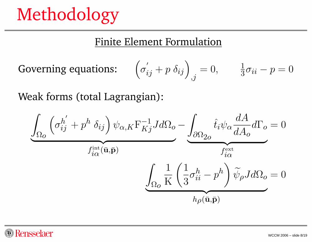
Methodology
Finite Element Formulation
Governing equations:(σ
′
ij + p δij
)
,j= 0, 1
3σii − p = 0
Weak forms (total Lagrangian):
∫
Ωo
(σh
′
ij + ph δij
)ψα,KF−1
KjJdΩo
︸ ︷︷ ︸f int
iα(u,p)
−
∫
∂Ω2o
tiψαdA
dAodΓo
︸ ︷︷ ︸fext
iα
= 0
∫
Ωo
1
K
(1
3σh
ii − ph
)ψρJdΩo
︸ ︷︷ ︸hρ(u,p)
= 0
WCCM 2006 – slide 8/19

Methodology
Finite Element Formulation
Linearized equations:
Kriαjβ ∆ujβ + Gr
iαϕ ∆pϕ = f extiα − f int
iα (ur, pr)
Hrρjβ ∆ujβ + Mr
ρϕ ∆pϕ = 0 − hρ (ur, pr)
Discontinuous pressure field allows for a ∆p solution on theelement level:
∆pϕ = −Mr−1
ϕρ
(hρ (ur, pr) + Hr
ρjβ ∆ujβ
)
WCCM 2006 – slide 9/19

Methodology
Transition from Damage Accumulation to Fatigue Cracking
F Trigger fatigue cracking with plastic damage metrics
F Fatigue cracks inserted in model (Cornell)
F Metrics for damage accumulation
F Total accumulated plastic slip over all slip systems
F Maximum accumulated plastic slip on a single slip
system
F Maximum accumulated plastic slip on a slip plane
WCCM 2006 – slide 10/19

Implementation
F Software developed in C++
F Developed within Cornell FEM framework
F Utilized MPICH for parallel processing
F PETSc used for solving global system of equations
MPICH
Crystal PlasticityModel
RPI
FemLib (Cornell)
RPIDriver
DriverCornell
PETSc
WCCM 2006 – slide 11/19

Implementation
F Running on large-scale systemsF SCOREC Medusa RedHat Linux cluster
? 32 nodes, dual Xeon 2.0 GHz processors, 2 GB RAM
F Cornell Theory Center Windows cluster? 170 nodes, dual Xeon 3.6 GHz processors, 4 GB RAM
F SDSC DataStar AIX Unix system (p655 partition)? 272 nodes, eight 1.5 GHz processors, 16 GB RAM
F Performance analysis [Scott Owens]
WCCM 2006 – slide 12/19

Calibration Results
Calibrated Material Parametersm 0.005 γo 1 s
−1
go 220 MPa µ 28.3 GPa
gs 250 MPa λ 60.9 GPa
Go 120 MPa η 5.1 GPa
WCCM 2006 – slide 13/19
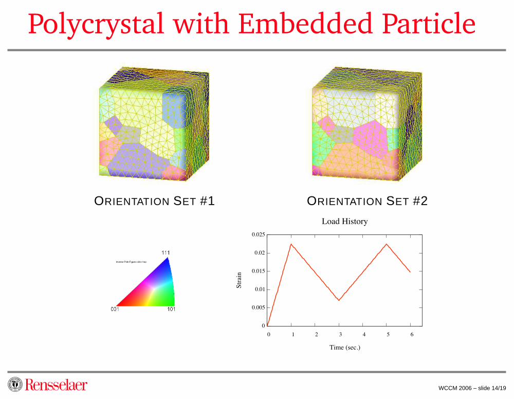
Polycrystal with Embedded Particle
ORIENTATION SET #1 ORIENTATION SET #2
WCCM 2006 – slide 14/19
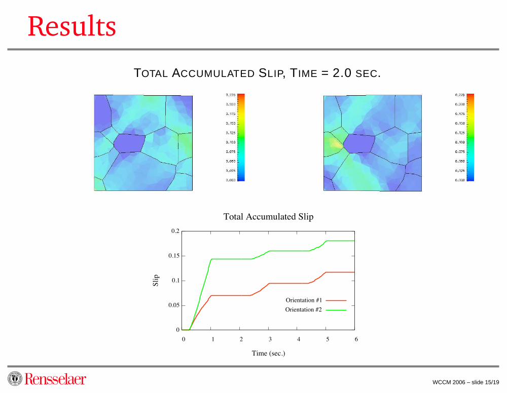
Results
TOTAL ACCUMULATED SLIP, TIME = 2.0 SEC.
WCCM 2006 – slide 15/19

Results
TOTAL ACCUMULATED SLIP, TIME = 4.0 SEC.
WCCM 2006 – slide 15/19

Results
TOTAL ACCUMULATED SLIP, TIME = 6.0 SEC.
WCCM 2006 – slide 15/19

Results
MAX ACCUMULATED SLIP ON SINGLE SLIP SYSTEM, TIME = 2.0 SEC.
WCCM 2006 – slide 16/19

Results
MAX ACCUMULATED SLIP ON SINGLE SLIP SYSTEM, TIME = 4.0 SEC.
WCCM 2006 – slide 16/19

Results
MAX ACCUMULATED SLIP ON SINGLE SLIP SYSTEM, TIME = 6.0 SEC.
WCCM 2006 – slide 16/19
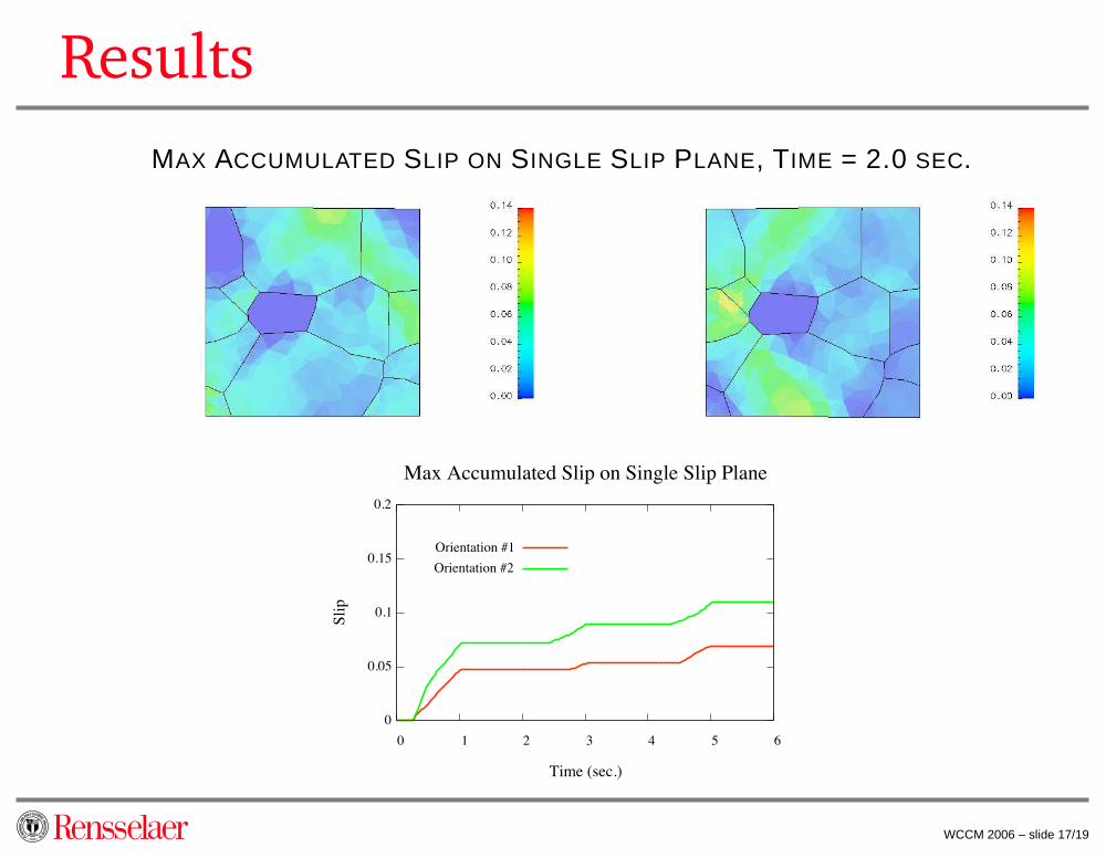
Results
MAX ACCUMULATED SLIP ON SINGLE SLIP PLANE, TIME = 2.0 SEC.
WCCM 2006 – slide 17/19

Results
MAX ACCUMULATED SLIP ON SINGLE SLIP PLANE, TIME = 4.0 SEC.
WCCM 2006 – slide 17/19

Results
MAX ACCUMULATED SLIP ON SINGLE SLIP PLANE, TIME = 6.0 SEC.
WCCM 2006 – slide 17/19

Future Work
F Project results into high-cycle regime
F Move between different time scales
F Fatigue crack insertion
F Dictated by plastic damage metrics
F FEM model altered to include crack (Cornell)
F Fatigue crack propagation
F Direction of propagation influenced by microstructure
F Particle-free zones
F Material properties altered near grain boundaries
WCCM 2006 – slide 18/19
Questions?
Application of Crystal Plasticity to FatigueDamage Modeling for Al 7075-T651
David Littlewood and Antoinette Maniatty
WCCM 2006 – slide 19/19

![Crystal Plasticity Finite Element Method[...]](https://static.fdocuments.net/doc/165x107/5863704f1a28ab0e30907cbf/crystal-plasticity-finite-element-method.jpg)