Application of Alumina/Graphene Nanocomposite to Enhance ...
20
1 Application of Alumina/Graphene Nanocomposite to Enhance the Surface Quality of Al7175-T74 Specimens S. Khalilpourazary 1,* , S.S. Meshkat 2 , J. Salehi 3 1,* Assistant professor, Faculty of Mechanical Engineering, Urmia University of Technology, Urmia, Iran 2 Assistant professor, Faculty of Chemical Engineering, Urmia University of Technology, Urmia, Iran 3 Bachelor, Faculty of Mechanical Engineering, Urmia University of Technology, Urmia, Iran Abstract: The burnishing process is one of the non-removal finishing processes, which is employed to enhance surface quality, corrosion property, and surface microhardness. In this study, the dry burnishing process was performed on the surface of Al7175-T74 specimens. Furthermore, nanofluid containing alumina/graphene nanocomposite was employed to perform the Nano burnishing process on the same specimens. The results show that the arithmetic surface roughness parameter in nanofluid burnished samples is decreased by approximately 0.277 μm, 0.233 μm, and 0.345 μm for the penetration depths of 0.2, 0.3, and 0.4mm comparing to those of dry burnishing process. Moreover, microhardness values in Nano and dry burnishing processes are directly related to the penetration depth parameter. The results reveal that the values of microhardness for the nanofluid burnished samples with four penetration depths of 0.2, 0.3, 0.4, and 0.5 mm are increased about 3, 28, 42, and 39 Vickers comparing to those values of dry burnishing process. The results prove that the minimum surface roughness and maximum microhardness values can be reached in Nano and dry roller burnishing processes at the penetration depth of 0.4 mm. Eventually, analyzing elements distribution on the surface of burnished aluminum alloy specimens confirm that the alumina/graphene nanocomposite embedded in the burnished surfaces during Nano burnishing process. Keywords: Roller Burnishing, Alumina, Graphene, Nanofluid, Surface Characteristics 1. Introduction ACCEPTED MANUSCRIPT
Transcript of Application of Alumina/Graphene Nanocomposite to Enhance ...
1
Application of Alumina/Graphene Nanocomposite to Enhance the Surface
Quality of Al7175-T74 Specimens
S. Khalilpourazary 1,*, S.S. Meshkat 2, J. Salehi3
1,*Assistant professor, Faculty of Mechanical Engineering, Urmia University of Technology, Urmia, Iran 2Assistant professor, Faculty of Chemical Engineering, Urmia University of Technology, Urmia, Iran
3Bachelor, Faculty of Mechanical Engineering, Urmia University of Technology, Urmia, Iran
Abstract:
The burnishing process is one of the non-removal finishing processes, which is employed to enhance
surface quality, corrosion property, and surface microhardness. In this study, the dry burnishing process
was performed on the surface of Al7175-T74 specimens. Furthermore, nanofluid containing
alumina/graphene nanocomposite was employed to perform the Nano burnishing process on the same
specimens. The results show that the arithmetic surface roughness parameter in nanofluid burnished
samples is decreased by approximately 0.277 μm, 0.233 μm, and 0.345 μm for the penetration depths of
0.2, 0.3, and 0.4mm comparing to those of dry burnishing process. Moreover, microhardness values in
Nano and dry burnishing processes are directly related to the penetration depth parameter. The results
reveal that the values of microhardness for the nanofluid burnished samples with four penetration depths
of 0.2, 0.3, 0.4, and 0.5 mm are increased about 3, 28, 42, and 39 Vickers comparing to those values of
dry burnishing process. The results prove that the minimum surface roughness and maximum
microhardness values can be reached in Nano and dry roller burnishing processes at the penetration depth
of 0.4 mm. Eventually, analyzing elements distribution on the surface of burnished aluminum alloy
specimens confirm that the alumina/graphene nanocomposite embedded in the burnished surfaces during
Nano burnishing process.
Keywords:
Roller Burnishing, Alumina, Graphene, Nanofluid, Surface Characteristics
1. Introduction
ACCEPTED MANUSCRIPT

2
Sequential finishing operations, such as grinding process, are employed to improve the surface quality
and overcome the design requirements of the specimens manufactured through conventional machining
processes. The finishing process as a subtractive process not only removes the materials in the chip form
but also requires extra expenses to purchase a new precision machine tool which increases the cost of
products [1] . Furthermore, the finishing process is of greater importance in lightweight metals such as
aluminum due to their wide applications in various industries. The burnishing process is one of the non-
removal machining processes, which is utilized to enhance surface quality, corrosion property, wear-
resistance, and surface resistance against fatigue [2]. In this method, there is no chip produced throughout
the process; also there is almost no need to use lubricant and coolant [3-5]. In the burnishing process the
applied tool pressure which is greater than yield strength limit of the material results in cold plastic
deformation on its surface. In other words, the combination of burnishing tool pressure and machine feed
rate along with burnished length decreases the height of surface peaks which in turn fills the valleys on
the surface in microscale. Previous researches have proved that the surface microhardness increases after
burnishing process due to the plastic deformation. The surface microhardness has a direct relationship
with the number of passes and the force applied to the workpiece surface during the burnishing process
[6-8]. To promote the performance of the burnishing process, a great deal of research has aimed at
studying the factors effective on it. The impressive parameters on the burnishing process can be divided
into i) the characteristics of the burnishing tool, ii) using or not using lubricant and coolant during the
process, iii) burnishing parameters such as speed, depth of penetration, and the number of passes and iv)
the workpiece material.
2. A survey on research conducted
Sachin et al. have studied the effect of minimum quantity lubrication (MQL) in the diamond burnishing
process of stainless steel [9]. The results declared that the suggested burnishing tool has a significant
effect to enhance the surface quality and surface hardness under MQL condition. Also, Sachin et al.
experimentally investigated the influence of the cryogenic diamond burnishing process on the surface
ACCEPTED MANUSCRIPT

3
quality and residual stress of 17-4 pH stainless steel [10]. The results revealed that the surface
quality/microhardness values are generally more decreased/increased in the suggested burnishing process
compared with MQL and dry burnishing processes. Ebeid and Ei-Taweel used a hybrid approach
combining electrochemical turning and roller burnishing processes to achieve minimum surface
roughness and maximum material removal rate on Al-Zn-Mg alloy workpieces [11]. The optimum input
parameters to gain this goal were determined via the Taguchi method. Luo et al. evaluated the effect of
burnishing parameters such as feed rate, workpiece speed, and penetration depth on the burnishing force
of the Al-alloy LY12 and Brass H62 in the turning process [12]. The results presented that the penetration
depth has the greatest impact on the burnishing force.
Özkul studied the effect of the force, feed rate, and the number of passes on the surface quality of Al6013
in the ball burnishing process [13]. To investigate the effect of these parameters on the surface quality
analysis of variance method (ANOVA) was employed. The results revealed that the high force and feed
ratio directly increase the final surface quality in the ball burnishing process. Also, experiments proved
that the number of passes has minimum effect on the surface quality.
Kalilpourazary and Salehi investigated the effect of alumina nanoparticles (ANs) nanofluid in the roller
burnishing process of Al7175 [14]. The roller burnishing process was performed in dry and nanofluid
types to scrutinize the final surface quality and microhardness values of the burnished samples. The input
parameters of the burnishing process were selected the same in both burnishing strategies. The results
indicated the use of the alumina nanofluid significantly increases the surface quality and surface
microhardness values comparing to the conventional dry burnishing process.
The effect of nanoparticles on the machining process can be studied in terms of the following concepts: i)
the type/size of nanoparticles being used, ii) the effect of nanoparticles on the characteristics of machined
surface such as surface quality and microhardness, and iii) the effect of nanoparticles on the tool wear,
tool life, etc. [15].
ACCEPTED MANUSCRIPT

4
The main goal of this research is to investigate the effect of alumina/graphene nanocomposite (AGNC)
dispersed in ethanol as a nanofluid on the surface quality and microhardness values in roller burnishing
process of Al7175.
In this study, each of the dry and AGNC burnishing processes was carried out on two separate groups of 5
samples made of Al7175-T74. The input parameters such as penetration depth, burnishing depth, number
of passes, feed rate, speed, and burnishing tool were selected to be the same for all the samples in the
burnishing process. To assess the effect of using AGNC in the burnishing process, the arithmetic surface
roughness (Ra), and microhardness parameters were investigated. Moreover, by using the Electron
Dispersion spectroscope (EDS), the elements on the surface of the Al7175 specimens after performing the
burnishing process were analyzed.
3. Materials and methods
The initial material used in experiments is Al7175-T74. It is a common aluminum alloy in industrial
applications such as automotive and aerospace industries due to its high machinability and formability. It
has the highest ductility compared to the other variants of 7175 aluminum. The chemical percentages of
the used Al7175-T74 are given in Table 1.
Table 1. Chemical composition of Al7175 (Temperature: 25 °C, Moisture: 29%).
other Si Cu Sb Pb Zn Mg Al Element
0.672 0.105 1.975 0.122 0.166 5.49 2.27 89.2 Weight (%)
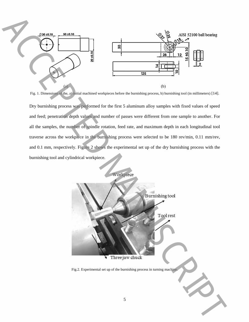
Before the burnishing, the machining process was performed on cylindrical workpieces of Al7175-T74 on
Colchester Tornado CNC turning machine. A roller bearing made of AISI 52100 with high carbon and
chromium content was used to perform the roller burnishing process on the CNC turning machine. Figure
1 reflects the machined workpieces and burnishing tool drawings (in millimeters).
ACCEPTED MANUSCRIPT
5
(a) (b)
Fig. 1. Dimensions of the, a) initial machined workpieces before the burnishing process, b) burnishing tool (in millimeters) [14].
Dry burnishing process was performed for the first 5 aluminum alloy samples with fixed values of speed
and feed; penetration depth values and number of passes were different from one sample to another. For
all the samples, the number of spindle rotation, feed rate, and maximum depth in each longitudinal tool
traverse across the workpiece in the burnishing process were selected to be 180 rev/min, 0.11 mm/rev,
and 0.1 mm, respectively. Figure 2 shows the experimental set up of the dry burnishing process with the
burnishing tool and cylindrical workpiece.
Fig.2. Experimental set up of the burnishing process in turning machine.
ACCEPTED MANUSCRIPT

6
Al7175-T74 contains hard silicon particles in the microstructure which can increase the tool wear rate.
Many scientists showed that aluminum series 7xxx can be machined effectively at low cutting speeds and
feeds [16, 17].
In the burnishing process, as the feed rate of the burnishing tool decreases, because of the long-time that
the burnishing tool is in contact with the surface of specimens, the bearing stress applied to the surface
increases and obtaining high surface quality becomes possible. Rotational speed 180 rev/min is selected
as an optimized value in aluminum series 7xxx burnishing process [18].
3-1- Nanofluid preparation
3-1-1- Alumina nanoparticles
To perform the burnishing process on the second group of aluminum alloy workpieces, a nanofluid
including AGNC was prepared. Alumina as a ceramic material has good physical property, high chemical
stability, and hardness [19]. General information to characterize the mechanical and thermal properties of
γ−Al2O3 nanoparticles are given in Table 2. In this paper, the used alumina nanoparticles have been
provided by Shanghai Xinglu Chemical Technology Co. Figure 3 presents a scanning electron
microscopy (SEM) image of the ANs.
Fig. 3. SEM image of the alumina nanoparticles.
ACCEPTED MANUSCRIPT

7
Table 2. Characteristics of the γ−Al2O3 nanoparticles [14].
Parameter Value
Purity 99%
Color White
Particle Average Size 50 nm
Morphology spherical
Density 3720 3Kg/m
3-1-2- Graphene
In this paper, graphene was employed as a carbon-based nanomaterial with a high surface area when
mixed with alumina nanoparticle [20-22]. Graphene with layered structure increases the lubrication
property of the metals surface and toughness [23]. Compared to the carbon nanotubes, graphene can be
homogeneously distributed in a matrix. The graphene layers are related to each other with weak Van Der
Waals forces, and their movement on each other improves lubrication characteristics.
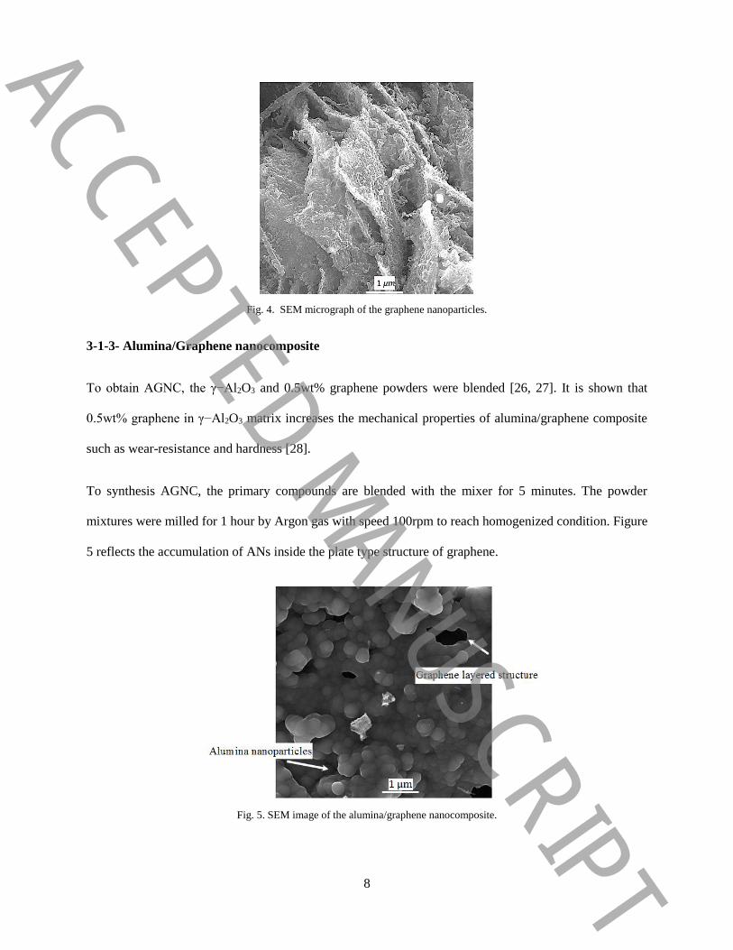
The graphene nanoparticles have been synthesized by the authors of this work using the chemical vapor
deposition (CVD) method. In this method, methane gas (CH4) was used as a carbon source. Also, NiO
nanoparticles were synthesized through Sol-gel process and were used as the Catalyst [24]. Methane gas
and hydrogen with ratio of 4:1 were utilized as the carrier gas in this method. A gas mixture was passed
through the quartz tube for 30 min, and the furnace was heated up to 900-1000 °C. To acquire the pure
nanoporous Graphene, the prepared graphene was stirred in acid solution (HCl) for about 16h then it was
rinsed with distilled water several times to achieve the neutral pH [25]. Figure 4 represents the
morphology of graphene nanoparticles with a layered structure.
ACCEPTED MANUSCRIPT
8
Fig. 4. SEM micrograph of the graphene nanoparticles.
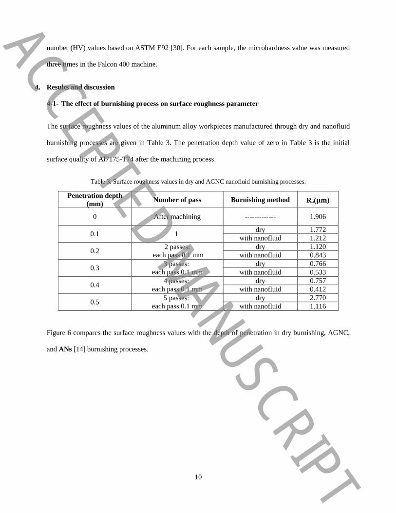
3-1-3- Alumina/Graphene nanocomposite
To obtain AGNC, the γ−Al2O3 and 0.5wt% graphene powders were blended [26, 27]. It is shown that
0.5wt% graphene in γ−Al2O3 matrix increases the mechanical properties of alumina/graphene composite
such as wear-resistance and hardness [28].
To synthesis AGNC, the primary compounds are blended with the mixer for 5 minutes. The powder
mixtures were milled for 1 hour by Argon gas with speed 100rpm to reach homogenized condition. Figure
5 reflects the accumulation of ANs inside the plate type structure of graphene.
Fig. 5. SEM image of the alumina/graphene nanocomposite.
ACCEPTED MANUSCRIPT

9
In this study, a carrier fluid including Ethanol alcohol (C2H5OH) named nanofluid is employed to deliver
AGNC to the workpiece surface in the burnishing process. Ethanol alcohol is a volatile liquid and
evaporates in room temperature, and has never been utilized as a coolant and lubricant in the machining
or burnishing processes. According to equation (1), AGNC is not soluble in Ethanol alcohol and there is
no chemical reaction among Ethanol alcohol, graphene, and ANs.
2 3 2 5 grapheneAl Al O C H OH C No Re action (1)
To provide the uniform AGNC in an Ethanol alcohol solution, an ultrasonic bath has been used for 5
minutes. According to the hydrophobic and hydrophilic groups on the graphene surface, graphene
solution in Ethanol alcohol is stable and stays uniform during the burnishing process; therefore the
graphene is not agglomerated in the inorganic solutions.
3-2- Nanofluid burnishing parameters
For five samples in the nanofluid burnishing process, the values for speed and feed rate were fixed.
However, the values for penetration depth and the number of passes were the same as those in the first
group. The speed, feed rate values, burnishing length, and maximum depth in each longitudinal tool
traverse across the workpiece were selected to be 180 rev/min, 0.11mm/rev, 50 mm, and 0.1 mm,
respectively.
3-3- Investigation the surface roughness and microhardness parameters
After the dry and nanofluid burnishing processes, the values for surface roughness and microhardness
were investigated. To obtain the surface quality of burnished specimens a portable surface roughness
device, model MarSurf TS1, was used. Then, the cut off length and the arithmetic surface roughness
values were assessed in both of the burnishing groups according to the ISO 4288 standard [29]. Each
burnished sample was investigated three times to ensure the accuracy of the measurements. Also, four
samples with penetration values of 0.2, 0.3, 0.4, and 0.5 mm were chosen to assess Vickers hardness
ACCEPTED MANUSCRIPT
10
number (HV) values based on ASTM E92 [30]. For each sample, the microhardness value was measured
three times in the Falcon 400 machine.
4. Results and discussion
4-1- The effect of burnishing process on surface roughness parameter
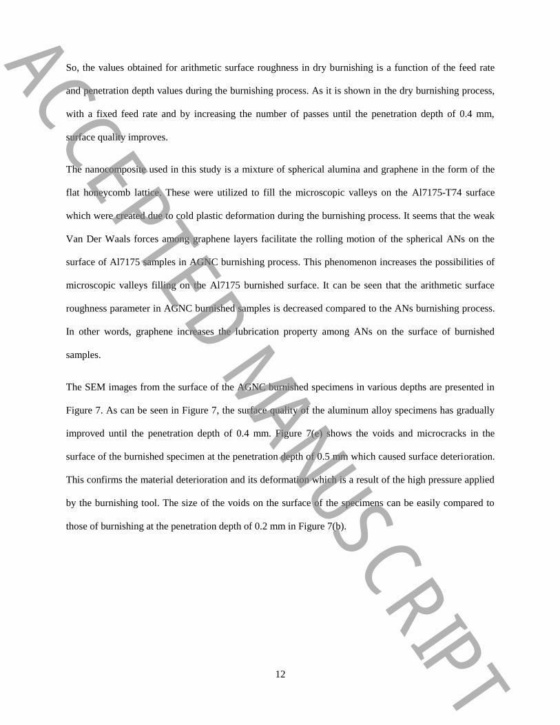
The surface roughness values of the aluminum alloy workpieces manufactured through dry and nanofluid
burnishing processes are given in Table 3. The penetration depth value of zero in Table 3 is the initial
surface quality of Al7175-T74 after the machining process.
Table 3. Surface roughness values in dry and AGNC nanofluid burnishing processes.
)𝛍𝐦(aR Burnishing method Number of pass Penetration depth
(mm)
1.906 ------------- After machining 0
1.772 dry 1 0.1
1.212 with nanofluid
1.120 dry 2 passes:
each pass 0.1 mm 0.2
0.843 with nanofluid
0.766 dry 3 passes:
each pass 0.1 mm 0.3
0.533 with nanofluid
0.757 dry 4 passes:
each pass 0.1 mm 0.4
0.412 with nanofluid
2.770 dry 5 passes:
each pass 0.1 mm 0.5
1.116 with nanofluid
Figure 6 compares the surface roughness values with the depth of penetration in dry burnishing, AGNC,
and ANs [14] burnishing processes.
ACCEPTED MANUSCRIPT

11
Fig. 6. Surface roughness versus depth of penetration in dry, AGNC and ANs burnishing processes.
According to the previous researches performing burnishing process on the surface of metals is, to a
certain depth, effective in decreasing surface roughness values; this depends on workpiece material,
machining parameters, and the type of burnishing tool. But generally after a while surface quality falls
due to material deterioration. Table 3 indicates that by performing burnishing in both dry and AGNC
burnishing processes, surface roughness values are continuously decreased until the penetration depth of
0.4 mm. These results are compared with ANs burnishing process [14] in Fig. 6. For all burnishing
processes, the surface roughness value reached its minimum value in the penetration depth of 0.4 mm and
thus the best surface quality is obtained. For the penetration depth of 0.5 mm, the surface experienced
deterioration, and surely the surface roughness value significantly increased compared to that of the
penetration depth of 0.4 mm. In this study, the burnishing feed rate was selected to be the minimum and
equal to 0.11 mm/rev. Based on previous researches, as the feed rate of the burnishing tool decreases,
because of the long time that the tool is in contact with the surface of specimens, the bearing stress
applied to the surface increases, and obtaining high surface quality becomes possible [14, 31]. From Table
3 it becomes apparent that by employing AGNC nanofluid in the penetration depth of 0.5 mm, the
arithmetic surface roughness value decreases by almost 1.6μm comparing to the dry burnishing process
ACCEPTED MANUSCRIPT
12
So, the values obtained for arithmetic surface roughness in dry burnishing is a function of the feed rate
and penetration depth values during the burnishing process. As it is shown in the dry burnishing process,
with a fixed feed rate and by increasing the number of passes until the penetration depth of 0.4 mm,
surface quality improves.
The nanocomposite used in this study is a mixture of spherical alumina and graphene in the form of the
flat honeycomb lattice. These were utilized to fill the microscopic valleys on the Al7175-T74 surface
which were created due to cold plastic deformation during the burnishing process. It seems that the weak
Van Der Waals forces among graphene layers facilitate the rolling motion of the spherical ANs on the
surface of Al7175 samples in AGNC burnishing process. This phenomenon increases the possibilities of
microscopic valleys filling on the Al7175 burnished surface. It can be seen that the arithmetic surface
roughness parameter in AGNC burnished samples is decreased compared to the ANs burnishing process.
In other words, graphene increases the lubrication property among ANs on the surface of burnished
samples.
The SEM images from the surface of the AGNC burnished specimens in various depths are presented in
Figure 7. As can be seen in Figure 7, the surface quality of the aluminum alloy specimens has gradually
improved until the penetration depth of 0.4 mm. Figure 7(e) shows the voids and microcracks in the
surface of the burnished specimen at the penetration depth of 0.5 mm which caused surface deterioration.
This confirms the material deterioration and its deformation which is a result of the high pressure applied
by the burnishing tool. The size of the voids on the surface of the specimens can be easily compared to
those of burnishing at the penetration depth of 0.2 mm in Figure 7(b).
ACCEPTED MANUSCRIPT

13
(c) (b) (a)
(e) (d)
Fig. 7. SEM Images of the burnished surfaces in AGNC burnishing process at (a) 0.1 mm, (b) 0.2 mm, (c) 0.3 mm, (d) 0.4 mm,
and (e) 0.5 mm penetration depth.
4-2- The rate of alumina/graphene nanocomposite embedded on the aluminum alloy burnished
surface in nanofluid burnishing process
In the present study, the EDS analysis of elements distribution is achieved using an EDS connected to an
SEM. Moreover, by using the EDS images of the surface of the AGNC burnished Al7175-T74 specimens
in various penetration depths; it is possible to specify the distribution of the elements on the surface and
to comprehend the presence of aluminum and oxygen elements in alumina and carbon element in
graphene. Since in this research the specimens are made of Al7175-T74, the images of aluminum element
cannot properly reveal the distribution of alumina nanoparticles on the AGNC burnished surfaces.
However, to evaluate the distribution of AGNC on the burnished surface, images of carbon and oxygen
ACCEPTED MANUSCRIPT

14
elements can be employed, respectively. Table 4 depicts the aluminum; oxygen and carbon elements
distribution on the surface of AGNC burnished samples.
Table 4. EDS images of oxygen, carbon, and aluminum distribution on the cylindrical surface of AGNC nanofluid
burnished samples.
Penetration
depth
(mm)
Element
Aluminum Oxygen Carbon
0.1
0.2
0.3
0.4
0.5
ACCEPTED MANUSCRIPT

15
The images of carbon and oxygen elements remarkably prove that the AGNC embeds on the surface of
aluminum alloy samples. Almost in all EDS images the amount of carbon and oxygen elements on the
surface increases as the penetration depth is chosen to be higher. Based on previous researches, the
presence of graphene on the surface of specimens has a positive effect on their mechanical behavior [32-
34]. For instance, when the temperature increases due to wear, the graphene on the surface of metals
changes into a sacrificial layer and increases the heat transfer as well as decreasing the temperature on the
surface of the workpiece. It can be elicit that the alumina graphene nanocomposite on the surface of the
aluminum alloy increases simultaneously the physical and heat transfer properties and can be used in the
aluminum shafts, and gears burnishing process for reaching high mechanical and thermal surface strength.
It is shown that the graphene has attracted great attention worldwide due to its unique combination of
mechanical and thermal properties [35, 36]. Thus, graphene is an ideal second phase to improve
simultaneously the mechanical, electrical, and thermal properties of metals, ceramics and polymers [37].
4-3- The effect of burnishing process on microhardness
To scrutinize the effect of the burnishing process on microhardness of Al7175-T74 specimens, the
average initial hardness values of this material were measured before the burnishing process. Four
samples of the specimens burnished through dry and AGNC burnishing processes at penetration depths of
0.2, 0.3, 0.4, and 0.5 mm were selected. It should be noted that the similarity of the parameters for both
the dry and AGNC burnishing processes makes the comparison of microhardness values easier. The
achieved values of microhardness of aluminum alloy workpieces manufactured through dry and AGNC
burnishing processes are presented in Table 5.
Table 5. The microhardness values of aluminum workpieces burnished by dry and AGNC nanofluid strategies.
Penetration depth (mm) Number of pass Burnishing
method
Microhardness
(HV)
Raw material ------------- ------------- 148
0.2 2 passes:
each pass 0.1 mm
dry 155
with nanofluid 158
0.3 3 passes:
each pass 0.1 mm
dry 164
with nanofluid 192
ACCEPTED MANUSCRIPT
16
0.4 4 passes:
each pass 0.1 mm
dry 173
with nanofluid 215
0.5 5 passes:
each pass 0.1 mm
dry 189
with nanofluid 228
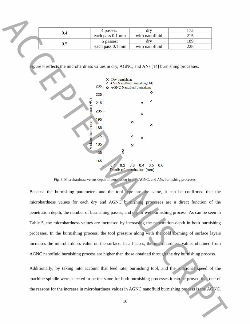
Figure 8 reflects the microhardness values in dry, AGNC, and ANs [14] burnishing processes.
Fig. 8. Microhardness versus depth of penetration in dry, AGNC, and ANs burnishing processes.
Because the burnishing parameters and the tool type are the same, it can be confirmed that the
microhardness values for each dry and AGNC burnishing processes are a direct function of the
penetration depth, the number of burnishing passes, and dry or wet burnishing process. As can be seen in
Table 5, the microhardness values are increased by increasing the penetration depth in both burnishing
processes. In the burnishing process, the tool pressure along with the cold forming of surface layers
increases the microhardness value on the surface. In all cases, the microhardness values obtained from
AGNC nanofluid burnishing process are higher than those obtained through the dry burnishing process.
Additionally, by taking into account that feed rate, burnishing tool, and the rotational speed of the
machine spindle were selected to be the same for both burnishing processes it can be proved that one of
the reasons for the increase in microhardness values in AGNC nanofluid burnishing process is the AGNC.
ACCEPTED MANUSCRIPT
17
Transferring AGNC by ethanol alcohol to the burnishing zone along with tool pressure and cold
deformation on the material surface traps the nanoparticles on the surface. The EDS images of the AGNC
burnished surfaces prove that the amount of oxygen element, as an element of alumina, increases with
increasing the penetration depth and at the penetration depth of 0.5 mm reach the maximum level.
Therefore, a high amount of embedded ANs can enhance the microhardness value on the surface of
burnished specimens.
Also, the EDS images of the AGNC nanofluid burnished surfaces show that the amount of carbon
element increases with increasing the penetration depth up to 0.5 mm. Previous researches confirmed that
graphene in Al2O3 matrix significantly increases the final hardness of the nanocomposite [23, 26, 27].
According to Fig. 8, the microhardness values obtained from AGNC nanofluid burnishing process are
higher than those obtained through the alumina nanofluid burnishing process. In Table 5, the low
difference of microhardness values in the penetration depth of 0.2 mm can be due to the limited plastic
deformation on the surface of the specimen which traps low AGNC.
5. Conclusions
As a novel method using nanofluid containing AGNC in the burnishing process was offered. Also, to
scrutinize the effects of nanocomposite on the surface characteristics of burnished samples, the results
were compared to those obtained from dry and ANs nanofluid burnishing processes. The results can be
summarized as follows:
1. Using dry and AGNC nanofluid burnishing processes in Al7175-T74 specimens continuously decrease
arithmetic surface roughness until the penetration depth of 0.4 mm.
2. By performing dry and AGNC nanofluid burnishing processes in the penetration depth of 0.5 mm the
surface of the specimens experience high deterioration and surface roughness parameter in this case
significantly increases compared to the penetration depth of 0.4 mm.
ACCEPTED MANUSCRIPT
18
3. The results showed that the arithmetic surface roughness parameter in AGNC nanofluid burnished
samples is decreased by approximately 0.277 μm, 0.233 μm, and 0.345 μm for the penetration depths of
0.2, 0.3, and 0.4mm comparing to those of dry burnishing process.
4. The results showed that the arithmetic surface roughness parameter in AGNC nanofluid burnished
samples is decreased approximately 0.14 μm, 0.231 μm, and 0.235 μm for the penetration depths of 0.2,
0.3, and 0.4mm comparing to those of ANs nanofluid burnishing process.
5. SEM images showed that the size of voids and cracks increased due to the surface deterioration of
Al7175-T74 samples at the penetration depth of 0.5 mm.
6. The difference in microhardness values enhanced by increasing the penetration depth in both
burnishing processes; in all cases, the microhardness values obtained from the nanofluid burnishing
process were higher than the dry and alumina burnishing process.
7. Figure 8 reflects that the values of microhardness for the AGNC nanofluid burnished samples with
four penetration depths of 0.2, 0.3, 0.4, and 0.5 mm are increased about 3 HV, 28 HV, 42 HV and 39 HV
comparing to those values of dry burnishing process.
8. Figure 8 reflects that the values of microhardness for the AGNC nanofluid burnished samples with
three penetration depths of 0.3, 0.4, and 0.5mm are increased by about 17 HV, 13 HV, and 11 HV
comparing to those values of ANs nanofluid burnishing process.
9. In dry and AGNC nanofluid burnishing processes of Al7175-T74 samples, minimum surface
roughness and high microhardness values can be reached at the penetration depth of 0.4 mm.
10. The EDS images proved that AGNC has embedded on the surface of burnished samples.
References
[1] M. El-Khabeery, M. El-Axir, Experimental techniques for studying the effects of milling roller-
burnishing parameters on surface integrity, International Journal of machine tools and manufacture,
41(12) (2001) 1705-1719.
[2] S. Sattari, A. Atrian, Investigation of deep rolling effects on the fatigue life of Al–SiC nanocomposite,
Materials Research Express, 5(1) (2018) 015052.
ACCEPTED MANUSCRIPT
19
[3] B. Buldum, S. Cagan, Study of ball burnishing process on the surface roughness and microhardness of
AZ91D alloy, Experimental Techniques, 42(2) (2018) 233-241.
[4] H. Luo, J. Liu, L. Wang, Q. Zhong, Investigation of the burnishing process with PCD tool on non-
ferrous metals, The International Journal of Advanced Manufacturing Technology, 25(5-6) (2005) 454-
459.
[5] D.S. Rao, H.S. Hebbar, M. Komaraiah, U. Kempaiah, Investigations on the effect of ball burnishing
parameters on surface hardness and wear resistance of HSLA dual-phase steels, Materials and
Manufacturing processes, 23(3) (2008) 295-302.
[6] M.S. John, N. Banerjee, K. Shrivastava, B. Vinayagam, Optimization of roller burnishing process on
EN-9 grade alloy steel using response surface methodology, Journal of the Brazilian Society of
Mechanical Sciences and Engineering, 39(8) (2017) 3089-3101.
[7] S. Randjelovic, B. Tadic, P.M. Todorovic, D. Vukelic, D. Miloradovic, M. Radenkovic, C. Tsiafis,
Modelling of the ball burnishing process with a high-stiffness tool, The International Journal of Advanced
Manufacturing Technology, 81(9-12) (2015) 1509-1518.
[8] W.B. Saï, J. Lebrun, Influence of finishing by burnishing on surface characteristics, Journal of
Materials Engineering and Performance, 12(1) (2003) 37-40.
[9] B. Sachin, S. Narendranath, D. Chakradhar, Sustainable diamond burnishing of 17-4 PH stainless steel
for enhanced surface integrity and product performance by using a novel modified tool, Materials
Research Express, 6(4) (2019) 046501.
[10] B. Sachin, S. Narendranath, D. Chakradhar, Effect of working parameters on the surface integrity in
cryogenic diamond burnishing of 17-4 PH stainless steel with a novel diamond burnishing tool, Journal of
Manufacturing Processes, 38 (2019) 564-571.
[11] S. Ebeid, T. Ei-Taweel, Surface improvement through hybridization of electrochemical turning and
roller burnishing based on the Taguchi technique, Proceedings of the Institution of Mechanical Engineers,
Part B: Journal of Engineering Manufacture, 219(5) (2005) 423-430.
[12] H. Luo, J. Liu, L. Wang, Q. Zhong, The effect of burnishing parameters on burnishing force and
surface microhardness, The International Journal of Advanced Manufacturing Technology, 28(7-8)
(2006) 707-713.
[13] I. Ozkul, Ball burnishing process effects on surface roughness for Al 6013 alloy, Turkish Journal of
Engineering, 3(1) (2019) 9.
[14] S. Khalilpourazary, J. Salehi, How alumina nanoparticles impact surface characteristics of Al7175 in
roller burnishing process, Journal of Manufacturing Processes, 39 (2019) 1-11.
[15] S. Khalilpourazary, S. Meshkat, Investigation of the effects of alumina nanoparticles on spur gear
surface roughness and hob tool wear in hobbing process, The International Journal of Advanced
Manufacturing Technology, 71(9-12) (2014) 1599-1610.
[16] B. Mills, Machinability of engineering materials, Springer Science & Business Media, 2012.
[17] J.G. Kaufman, Introduction to aluminum alloys and tempers, ASM international, 2000.
[18] U.G.-T.M.P. PROCESU, Use of grey based Taguchi method in ball burnishing process for the
optimization of surface roughness and microhardness of AA 7075 aluminum alloy, Materiali in
tehnologije, 44(3) (2010) 129-135.
[19] S. Said, S. Mikhail, M. Riad, Recent processes for the production of alumina nano-particles,
Materials Science for Energy Technologies, 3 (2020) 344-363.
[20] Z. Ma, X. Zhao, Q. Tang, Z. Zhou, Computational prediction of experimentally possible g-C3N3
monolayer as hydrogen purification membrane, international journal of hydrogen energy, 39(10) (2014)
5037-5042.
[21] T. Huang, Y. Xin, T. Li, S. Nutt, C. Su, H. Chen, P. Liu, Z. Lai, Modified graphene/polyimide
nanocomposites: reinforcing and tribological effects, ACS applied materials & interfaces, 5(11) (2013)
4878-4891.
[22] J. Wang, Z. Li, G. Fan, H. Pan, Z. Chen, D. Zhang, Reinforcement with graphene nanosheets in
aluminum matrix composites, Scripta Materialia, 66(8) (2012) 594-597.
ACCEPTED MANUSCRIPT
20
[23] R. Jiang, H. Zhu, Y. Fu, S. Jiang, E. Zong, J. Yao, Photocatalytic decolorization of Congo red
wastewater by magnetic ZnFe2O4/graphene nanosheets composite under simulated solar light irradiation,
Ozone: Science & Engineering, 42(2) (2020) 174-182.
[24] N.N.M. Zorkipli, N.H.M. Kaus, A.A. Mohamad, Synthesis of NiO nanoparticles through sol-gel
method, Procedia chemistry, 19 (2016) 626-631.
[25] S. Pourmand, M. Abdouss, A. Rashidi, Preparation of nanoporous graphene via nanoporous zinc
oxide and its application as a nanoadsorbent for benzene, toluene and xylenes removal, International
Journal of Environmental Research, 9(4) (2015) 1269-1276.
[26] E. Klyatskina, A. Borrell, E. Grigoriev, A. Zholnin, M. Salvador, V. Stolyarov, Structure features
and properties of graphene/Al 2 O 3 composite, J. Ceram. Sci. Technol, 9 (2018) 215-224.
[27] X. Liu, Y.C. Fan, Q. Feng, L.J. Wang, W. Jiang, Preparation of graphene nanosheet/alumina
composites, in: Materials Science Forum, Trans Tech Publ, 2013, pp. 534-538.
[28] A.K. Sharma, A.K. Tiwari, A.R. Dixit, Progress of nanofluid application in machining: a review,
Materials and Manufacturing Processes, 30(7) (2015) 813-828.
[29] D.E. ISO, Geometrical Product Specifications (GPS)—Surface Texture: Profile Method: Rules and
Procedures for the Assessment of Surface Texture, (1996).
[30] E. ASTM, 92: 2003: Standard Test Method for Vickers Hardness of Metallic Materials, ASTM
International, (2006).
[31] J. Maximov, A. Anchev, G. Duncheva, N. Ganev, K. Selimov, Influence of the process parameters
on the surface roughness, micro-hardness, and residual stresses in slide burnishing of high-strength
aluminum alloys, Journal of the Brazilian Society of Mechanical Sciences and Engineering, 39(8) (2017)
3067-3078.
[32] A.D. Moghadam, E. Omrani, P.L. Menezes, P.K. Rohatgi, Mechanical and tribological properties of
self-lubricating metal matrix nanocomposites reinforced by carbon nanotubes (CNTs) and graphene–a
review, Composites Part B: Engineering, 77 (2015) 402-420.
[33] L.-Y. Lin, D.-E. Kim, W.-K. Kim, S.-C. Jun, Friction and wear characteristics of multi-layer
graphene films investigated by atomic force microscopy, Surface and Coatings Technology, 205(20)
(2011) 4864-4869.
[34] S.F. Bartolucci, J. Paras, M.A. Rafiee, J. Rafiee, S. Lee, D. Kapoor, N. Koratkar, Graphene–
aluminum nanocomposites, Materials Science and Engineering: A, 528(27) (2011) 7933-7937.
[35] A.A. Balandin, S. Ghosh, W. Bao, I. Calizo, D. Teweldebrhan, F. Miao, C.N. Lau, Superior thermal
conductivity of single-layer graphene, Nano letters, 8(3) (2008) 902-907.
[36] L.S. Walker, V.R. Marotto, M.A. Rafiee, N. Koratkar, E.L. Corral, Toughening in graphene ceramic
composites, ACS nano, 5(4) (2011) 3182-3190.
[37] M. Liu, C. Chen, J. Hu, X. Wu, X. Wang, Synthesis of magnetite/graphene oxide composite and
application for cobalt (II) removal, The Journal of Physical Chemistry C, 115(51) (2011) 25234-25240.
ACCEPTED MANUSCRIPT