Application Note Electric Power Steering (EPS)
16
October 2008 Sensors Application Note V 0.1 Electric Power Steering (EPS) with GMR-Based Angular and Linear Hall Sensor
Transcript of Application Note Electric Power Steering (EPS)

October 2008
Sensors
Appl icat ion NoteV 0.1
Electr ic Power Steer ing (EPS)with GMR-Based Angular and Linear Hal l Sensor

Edition 2008-10-23Published byInfineon Technologies AG81726 München, Germany© 2007 Infineon Technologies AGAll Rights Reserved.
Legal DisclaimerThe information given in this document shall in no event be regarded as a guarantee of conditions or characteristics. With respect to any examples or hints given herein, any typical values stated herein and/or any information regarding the application of the device, Infineon Technologies hereby disclaims any and all warranties and liabilities of any kind, including without limitation, warranties of non-infringement of intellectual property rights of any third party.
InformationFor further information on technology, delivery terms and conditions and prices, please contact the nearest Infineon Technologies Office (www.infineon.com).
WarningsDue to technical requirements, components may contain dangerous substances. For information on the types in question, please contact the nearest Infineon Technologies Office.Infineon Technologies components may be used in life-support devices or systems only with the express written approval of Infineon Technologies, if a failure of such components can reasonably be expected to cause the failure of that life-support device or system or to affect the safety or effectiveness of that device or system. Life support devices or systems are intended to be implanted in the human body or to support and/or maintain and sustain and/or protect human life. If they fail, it is reasonable to assume that the health of the user or other persons may be endangered.

Application Note 3 V 0.1, 2008-10-23
Electric Power Steering
We Listen to Your CommentsAny information within this document that you feel is wrong, unclear or missing at all? Your feedback will help usto continously improve the quality of this document. Please send your proposal (including a reference to thisdocument) to:[email protected]
Electric Power Steering (EPS) with GMR-Based Angular and Linear Hall Sensor Revision History: 2008-10-23, V 0.1Previous Version: Page Subjects (major changes since last revision)
Electric Power Steering
Table of Contents
Application Note 4 V 0.1, 2008-10-23
Table of Contents . . . . . . . . . . . . . . . . . . . . . . . . . . . . . . . . . . . . . . . . . . . . . . . . . . . . . . . . . . . . . . . . 4
List of Figures . . . . . . . . . . . . . . . . . . . . . . . . . . . . . . . . . . . . . . . . . . . . . . . . . . . . . . . . . . . . . . . . . . . 5
1 Electric Power Steering with GMR-based Angular Sensors . . . . . . . . . . . . . . . . . . . . . . . . . . . . . . 71.1 Introduction . . . . . . . . . . . . . . . . . . . . . . . . . . . . . . . . . . . . . . . . . . . . . . . . . . . . . . . . . . . . . . . . . . . . . . 7
2 EPS Systems . . . . . . . . . . . . . . . . . . . . . . . . . . . . . . . . . . . . . . . . . . . . . . . . . . . . . . . . . . . . . . . . . . . . 72.1 EPS Electric Control Unit . . . . . . . . . . . . . . . . . . . . . . . . . . . . . . . . . . . . . . . . . . . . . . . . . . . . . . . . . . . 8
3 Infineon Sensors . . . . . . . . . . . . . . . . . . . . . . . . . . . . . . . . . . . . . . . . . . . . . . . . . . . . . . . . . . . . . . . . . 93.1 Infineon Angle Sensors . . . . . . . . . . . . . . . . . . . . . . . . . . . . . . . . . . . . . . . . . . . . . . . . . . . . . . . . . . . . . 93.1.1 TLE5011 . . . . . . . . . . . . . . . . . . . . . . . . . . . . . . . . . . . . . . . . . . . . . . . . . . . . . . . . . . . . . . . . . . . . . . 93.1.2 TLE5012 . . . . . . . . . . . . . . . . . . . . . . . . . . . . . . . . . . . . . . . . . . . . . . . . . . . . . . . . . . . . . . . . . . . . . . 93.2 Infineon’s Linear Hall Sensors . . . . . . . . . . . . . . . . . . . . . . . . . . . . . . . . . . . . . . . . . . . . . . . . . . . . . . . 93.2.1 TLE4990 . . . . . . . . . . . . . . . . . . . . . . . . . . . . . . . . . . . . . . . . . . . . . . . . . . . . . . . . . . . . . . . . . . . . . 103.2.2 TLE4997 . . . . . . . . . . . . . . . . . . . . . . . . . . . . . . . . . . . . . . . . . . . . . . . . . . . . . . . . . . . . . . . . . . . . . 103.2.3 TLE4998P . . . . . . . . . . . . . . . . . . . . . . . . . . . . . . . . . . . . . . . . . . . . . . . . . . . . . . . . . . . . . . . . . . . . 103.2.4 TLE4998S . . . . . . . . . . . . . . . . . . . . . . . . . . . . . . . . . . . . . . . . . . . . . . . . . . . . . . . . . . . . . . . . . . . . 103.2.5 TLE4998C . . . . . . . . . . . . . . . . . . . . . . . . . . . . . . . . . . . . . . . . . . . . . . . . . . . . . . . . . . . . . . . . . . . . 10
4 Rotor Position Sensor . . . . . . . . . . . . . . . . . . . . . . . . . . . . . . . . . . . . . . . . . . . . . . . . . . . . . . . . . . . 11
5 Steering-Angle Sensor . . . . . . . . . . . . . . . . . . . . . . . . . . . . . . . . . . . . . . . . . . . . . . . . . . . . . . . . . . . 13
6 Torque Sensor . . . . . . . . . . . . . . . . . . . . . . . . . . . . . . . . . . . . . . . . . . . . . . . . . . . . . . . . . . . . . . . . . 14
Table of Contents

Electric Power Steering
List of Figures
List of Figures
Figure 1 EPS Systems . . . . . . . . . . . . . . . . . . . . . . . . . . . . . . . . . . . . . . . . . . . . . . . . . . . . . . . . . . . . . . . . . . 7Figure 2 EPS Application . . . . . . . . . . . . . . . . . . . . . . . . . . . . . . . . . . . . . . . . . . . . . . . . . . . . . . . . . . . . . . . . 8Figure 3 EPS Block Diagram . . . . . . . . . . . . . . . . . . . . . . . . . . . . . . . . . . . . . . . . . . . . . . . . . . . . . . . . . . . . . 8Figure 4 Possible setup for rotor position detection (1) . . . . . . . . . . . . . . . . . . . . . . . . . . . . . . . . . . . . . . . . 11Figure 5 Possible setup for rotor position detection (2) . . . . . . . . . . . . . . . . . . . . . . . . . . . . . . . . . . . . . . . . 11Figure 6 Additional angle error vs. motor-speed. . . . . . . . . . . . . . . . . . . . . . . . . . . . . . . . . . . . . . . . . . . . . . 12Figure 7 Excitation signal of one coil vs. rotor position . . . . . . . . . . . . . . . . . . . . . . . . . . . . . . . . . . . . . . . . . 12Figure 8 Possible Setup for Steering-Angle Sensor . . . . . . . . . . . . . . . . . . . . . . . . . . . . . . . . . . . . . . . . . . . 13Figure 9 Output . . . . . . . . . . . . . . . . . . . . . . . . . . . . . . . . . . . . . . . . . . . . . . . . . . . . . . . . . . . . . . . . . . . . . . . 13Figure 10 Torsion Bar . . . . . . . . . . . . . . . . . . . . . . . . . . . . . . . . . . . . . . . . . . . . . . . . . . . . . . . . . . . . . . . . . . . 14Figure 11 Torque Sensor - Rotor . . . . . . . . . . . . . . . . . . . . . . . . . . . . . . . . . . . . . . . . . . . . . . . . . . . . . . . . . . 14Figure 12 Torque Sensor - Stator . . . . . . . . . . . . . . . . . . . . . . . . . . . . . . . . . . . . . . . . . . . . . . . . . . . . . . . . . . 14Figure 13 Torque sensor - Concentrator with Sensor. . . . . . . . . . . . . . . . . . . . . . . . . . . . . . . . . . . . . . . . . . . 15
Application Note 5 V 0.1, 2008-10-23

Electric Power Steering
List of Figures
Application Note 6 V 0.1, 2008-10-23

Application Note 7 V 0.1, 2008-10-23
Electric Power Steering
Electric Power Steering with GMR-based Angular Sensors
1 Electric Power Steering with GMR-based Angular Sensors
1.1 IntroductionPower steering is a system for reducing the steering effort on cars by using an external power source to assist inturning the wheels.Electro Hydraulic Power Steering (EHPS) is an advanced system that uses conventional hydraulic power steeringwith an electric motor-driven hydraulic pump.Electric Power Steering (EPS) is the latest system in which the electric motor (“E-motor”) is attached directly to thesteering gearbox without a hydraulic system. Sensors detect the motion of the steering column and a processormodule applies assistive power via an electric motor. This allows varying amounts of assistance depending ondriving conditions.With electronic systems becoming more and more common in cars, EPS is the future power steering system thatthey will use. Unlike its conventional counterpart, EPS is active only during the actual steering process. It alsoeliminates maintenance on steering hydraulics and cuts fuel consumption by as much as 0.4 l/100 km.
2 EPS SystemsDifferent EPS systems are in use (see Figure 1).
Figure 1 EPS Systems
Which EPS type will be used depends on the steering rack force (see Figure 2). The column drive is used for small and lower mid-sized cars. The motor is located in the passenger compartment.Its advantage is its better performance at reduced temperatures, and sealing.The pinion drive is used for mid-sized cars, and the dual pinion drive is used for upper mid-sized cars. Both ofthese drives are located in the engine compartment.Another possibility is the rack drive. This type is appropriate for large vehicles such as Sports Utility Vehicles(SUVs) and trucks.
Source: IQPC Advanced Steering Systems, ZF Lenksysteme, Dr.G.Ruck, May 2006
Column Type Pinion Type Dual Pinion Type APA Rack Type

Electric Power Steering
EPS Systems
Application Note 8 V 0.1, 2008-10-23
Figure 2 EPS Application
2.1 EPS Electric Control UnitEach EPS Electric Control Unit (ECU) handles the data from different sensors. The sensors send informationabout the steering torque, driving speed, and the steering angle. Figure 3 is an example of a block diagram of anEPS ECU. Using this information from the sensors, the ECU calculates the necessary steering assist and controlsthe 3-Phase Driver.
Figure 3 EPS Block Diagram
Car Segments150001400013000
Upper Segment 1200011000105001000095009000
Middle Segment 850080007500
Small Car 7000Mini 6500
Servolectric with 12V
LowerMiddle Segment
UpperMiddle Segment
SUV/Trucks
Steering RackForce [N] Column Pinion Dual Pinion APA - Rack
Withadvancedsteeringtechnology
EPSc high…
Source: IQPC Advanced Steering Systems, ZF Lenksysteme, Dr.G.Ruck, May 2006
Differential Hall IC
TLE4941/42
8-Bit Microcontroller
XC866
16-/32-Bit Microcontroller
XC2364
CAN/LINTransceiver
TLE6251DS/G,
TLE6258,6285G
Senso
r In
terf
ace
(opti
nal)
TrackerTLE4250/51
SupplyICsTLE 6361TLE 6389
OptiMOS-T 40V
IBP180N04S3-02
IBP180N04S3-H2
x 6
Rotor Position
HS-CAN-Bus
Fail Safe
SteeringAngle
Torque
Speed
+12V Rail
Rotor Position
TLE5011/12
Current Sense(Shunt
Substitute )2xTLE4990/98
3-P
hase D
river
IC
TLE
718
3F
TLE
718
9F
TLE
71
8X
Master
Electric Power
SteeringECU
TLE5011TLE4998
Torque Sensor
Steering Angle Sensor
2x TLE5011/12
8-Bit Microcontroller
XC866/8
Application Note 9 V 0.1, 2008-10-23
Electric Power Steering
Infineon Sensors
3 Infineon Sensors
3.1 Infineon Angle SensorsInfineon offers some angle sensors based on GMR technology. This section gives a short overview of Infineon’sangle-sensor portfolio. For more detailed information, please refer to the products’ individual datasheets.
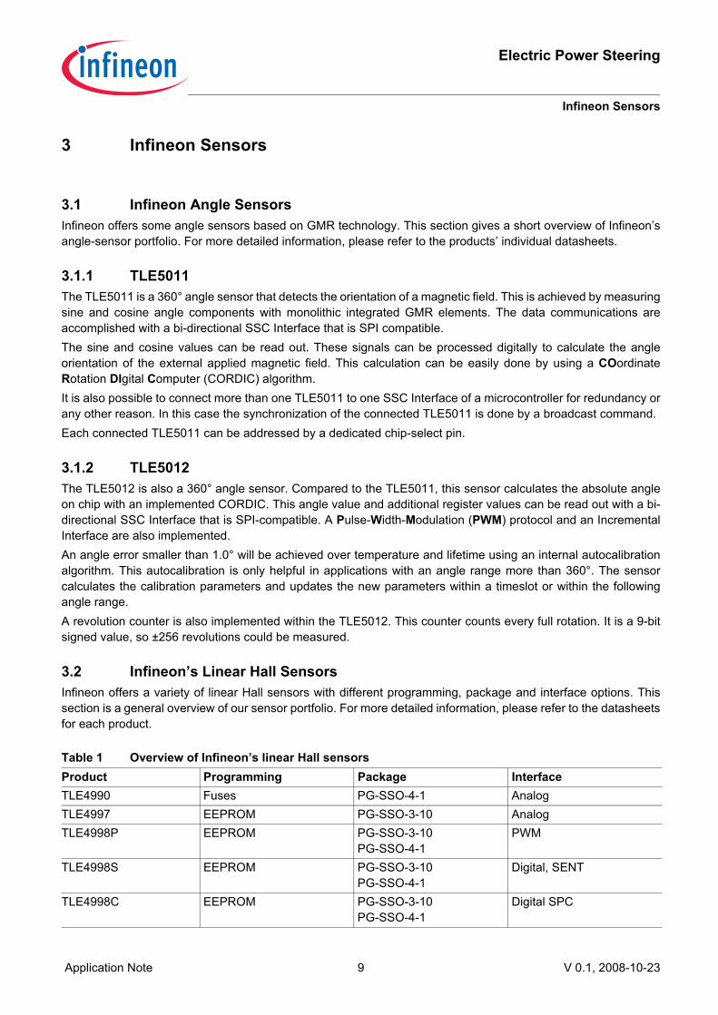
3.1.1 TLE5011The TLE5011 is a 360° angle sensor that detects the orientation of a magnetic field. This is achieved by measuringsine and cosine angle components with monolithic integrated GMR elements. The data communications areaccomplished with a bi-directional SSC Interface that is SPI compatible. The sine and cosine values can be read out. These signals can be processed digitally to calculate the angleorientation of the external applied magnetic field. This calculation can be easily done by using a COordinateRotation DIgital Computer (CORDIC) algorithm.It is also possible to connect more than one TLE5011 to one SSC Interface of a microcontroller for redundancy orany other reason. In this case the synchronization of the connected TLE5011 is done by a broadcast command.Each connected TLE5011 can be addressed by a dedicated chip-select pin.
3.1.2 TLE5012The TLE5012 is also a 360° angle sensor. Compared to the TLE5011, this sensor calculates the absolute angleon chip with an implemented CORDIC. This angle value and additional register values can be read out with a bi-directional SSC Interface that is SPI-compatible. A Pulse-Width-Modulation (PWM) protocol and an IncrementalInterface are also implemented.An angle error smaller than 1.0° will be achieved over temperature and lifetime using an internal autocalibrationalgorithm. This autocalibration is only helpful in applications with an angle range more than 360°. The sensorcalculates the calibration parameters and updates the new parameters within a timeslot or within the followingangle range. A revolution counter is also implemented within the TLE5012. This counter counts every full rotation. It is a 9-bitsigned value, so ±256 revolutions could be measured.
3.2 Infineon’s Linear Hall SensorsInfineon offers a variety of linear Hall sensors with different programming, package and interface options. Thissection is a general overview of our sensor portfolio. For more detailed information, please refer to the datasheetsfor each product.
Table 1 Overview of Infineon’s linear Hall sensorsProduct Programming Package InterfaceTLE4990 Fuses PG-SSO-4-1 AnalogTLE4997 EEPROM PG-SSO-3-10 AnalogTLE4998P EEPROM PG-SSO-3-10
PG-SSO-4-1PWM
TLE4998S EEPROM PG-SSO-3-10PG-SSO-4-1
Digital, SENT
TLE4998C EEPROM PG-SSO-3-10PG-SSO-4-1
Digital SPC

Electric Power Steering
Infineon Sensors
Application Note 10 V 0.1, 2008-10-23
3.2.1 TLE4990The TLE4990 is Infineon's basic linear Hall sensor with analog signal processing and fuse programmability. Thesensor is end-of-line programmable, meaning that its gain and sensitivity can be set in a two-point calibration inthe module. Due to its thin PG-SSO-4-1 package, it fits in small air gaps. The TLE4990 has been field-proven overthe last few years and is well established for automotive applications such as gas-pedal position sensing.
3.2.2 TLE4997The TLE4997 has been designed to improve on some of the shortcomings of an analog compensation scheme asthe one used in the TLE4990 and most competing products, including offset and sensitivity drifts over temperature,range of the programmable parameters, and accuracy. The signal processing in the TLE4997 is entirely shifted tothe digital domain, making the influence of the programmed parameters completely deterministic. Temperatureeffects of the Hall probe can readily be compensated for by pre-calibration in Infineon's fabrication. The TLE4997is also the first sensor on the market that offers independent, programmable parameters for both first- and second-order temperature coefficients of the application sensitivity. The TLE4997 has an analog, ratiometric output andcan be used as a robust replacement for potentiometers. It comes in a small 3-pin PG-SSO-3-10 package and istherefore suited for use in the limited space inside magnetic circuits.
3.2.3 TLE4998PThe TLE4998 family is the successor of the TLE4997, providing innovations on the interface side. The signalprocessing concept is based on the TLE4997 design, offering high-precision analog-to-digital signal conversionand a deterministic digital signal processing. The TLE4998P features a PWM interface in which the duty cyclecarries the Hall signal information. It offers 12-bit resolution on the output, and combined with accurate detectionon the microcontroller side, is more accurate than an analog interface.
3.2.4 TLE4998SThe TLE4998S is equivalent to the TLE4998P except for the interface, which is implemented as SAE's1) SingleEdge Nibble Transmission (SENT) standard. SENT offers a low-cost alternative to CAN and LIN, but stillincorporates a coded digital signal transmission with a Cyclic Redundancy Check (CRC) to check the validity of atransmission. Apart from an industry-leading 16-bit Hall value, the transmitted SENT frame includes 8-bittemperature information and 4-bit sensor status information. The status information finally allows for a massiveimprovement of overall system safety.
3.2.5 TLE4998CThe TLE4998C features a Short PWM Code (SPC) protocol, which is an extension to the standard SENT protocoland therefore has all the advantages already present in the TLE4998S such as high resolution, status,temperature, and CRC information. The sensor does not, however, send out the measured values indefinitely, butonly after being triggered by the ECU. This functionality permits synchronized transmission of data. The protocolmakes it possible to select one of four sensors, which are connected to a single bus line.
1) SAE: Society of Automotive Engineers

Application Note 11 V 0.1, 2008-10-23
Electric Power Steering
Rotor Position Sensor
4 Rotor Position SensorThe rotor position is very important for correct commutation of the motor, independent of the motor type(Permanent Magnet Synchronous Motor (PMSM); Brush Less Direct Current (BLDC); Asynchronous Motor(ASM)). For detection of rotor position, a TLE5011 or TLE5012 could be used as depicted in Figure 4 a.Figure 5.
Figure 4 Possible setup for rotor position detection (1)
Figure 5 Possible setup for rotor position detection (2)
The angle information tells the system which coil has to be excited next. The angle detection has to be done veryfast. Depending on the number of poles used and the rotation speed, an additional error has to be considered forthe electrical commutation, which is depicted in Figure 6. With one pole pair, the electrical 360° (one period)matches the mechanical 360° (one rotation). With a rotor with two pole pairs, the switching in the coils has to bedone two times faster. This means the electrical period must be completed within a half rotation (Figure 7).
EC-Motor Magnet
Sensor
Pinion Gear
Sensor
EC-Motor MagnetPinion Gear

Electric Power Steering
Rotor Position Sensor
Application Note 12 V 0.1, 2008-10-23
Figure 6 Additional angle error vs. motor-speed
Figure 7 Excitation signal of one coil vs. rotor position
Additional Angle Error vs. Application Speed (Sensor Update Rate = 80µs)
0,01
0,1
1
10
100
100 1000 10000 100000
Motor-Speed [1/min]
Ang
le E
rror
[°]
PP=1 PP=2 PP=3 PP=4 PP=5
Mech. Angle
0° 360°
Excitation Signal of one coil with 1
polpair
Excitation Signal of one coil with 2
polpairs
180°
Application Note 13 V 0.1, 2008-10-23
Electric Power Steering
Steering-Angle Sensor
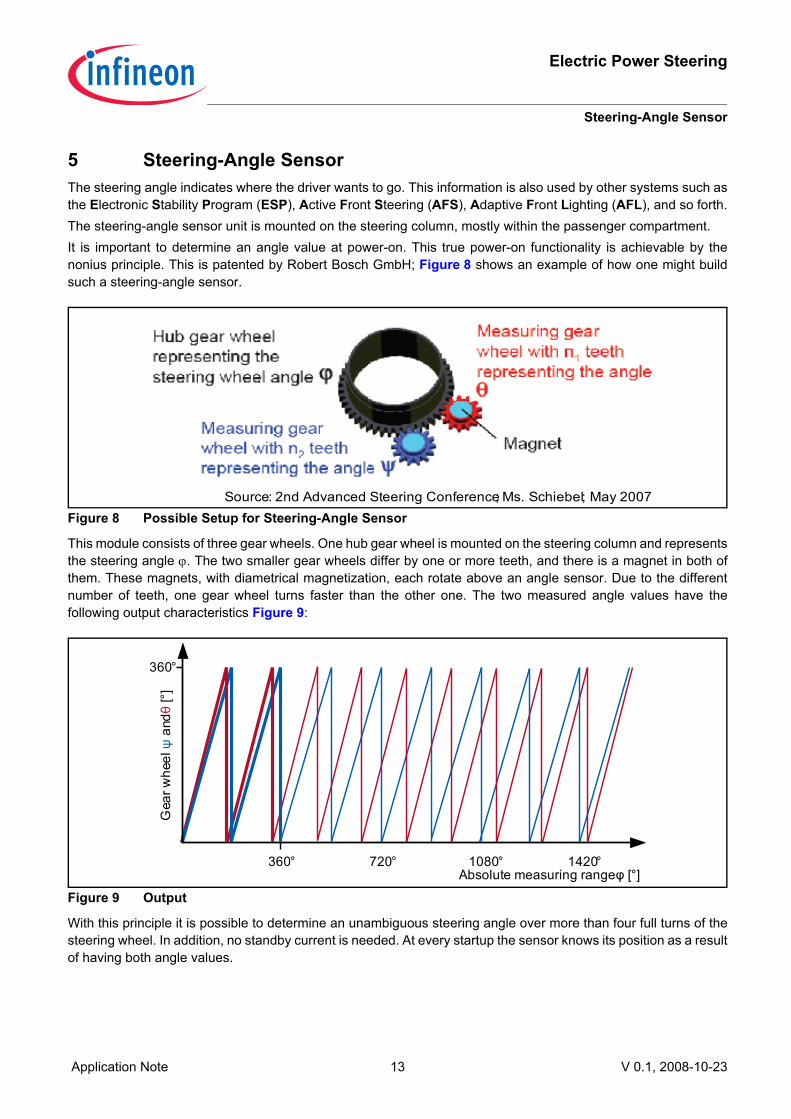
5 Steering-Angle SensorThe steering angle indicates where the driver wants to go. This information is also used by other systems such asthe Electronic Stability Program (ESP), Active Front Steering (AFS), Adaptive Front Lighting (AFL), and so forth.The steering-angle sensor unit is mounted on the steering column, mostly within the passenger compartment.It is important to determine an angle value at power-on. This true power-on functionality is achievable by thenonius principle. This is patented by Robert Bosch GmbH; Figure 8 shows an example of how one might buildsuch a steering-angle sensor.
Figure 8 Possible Setup for Steering-Angle Sensor
This module consists of three gear wheels. One hub gear wheel is mounted on the steering column and representsthe steering angle ϕ. The two smaller gear wheels differ by one or more teeth, and there is a magnet in both ofthem. These magnets, with diametrical magnetization, each rotate above an angle sensor. Due to the differentnumber of teeth, one gear wheel turns faster than the other one. The two measured angle values have thefollowing output characteristics Figure 9:
Figure 9 Output
With this principle it is possible to determine an unambiguous steering angle over more than four full turns of thesteering wheel. In addition, no standby current is needed. At every startup the sensor knows its position as a resultof having both angle values.
Source: 2nd Advanced Steering Conference; Ms. Schiebel; May 2007
360°
Gea
r whe
el ψ
andθ
[°]
360°Absolute measuring range φ [°]
720° 1080° 1420°

Electric Power Steering
Torque Sensor
Application Note 14 V 0.1, 2008-10-23
6 Torque SensorThe power-steering control unit uses a torque sensor as the main input for determining the amount of steeringassistance needed. The steering column is split into two parts: The input shaft, from the steering wheel to thetorque sensor; and the output shaft, from the torque sensor to the steering shaft coupler. The input and outputshafts are separated by a torsion bar (Figure 10), where the torque sensor is located. The torque sensormeasures the shift angle between input and output shaft. One possible torque sensor from Moving MagnetTechologies (MMT) is described below. Please note that this design is covered by a patent1) and should give onlyan idea how to implement torque sensing with linear Hall sensors.
Figure 10 Torsion Bar
The sensor by itself is split into two parts, the rotor and the stator. The rotor, a multipole magnet ring, is mountedon one side of the shaft (Figure 11).
Figure 11 Torque Sensor - Rotor
The stator consists of two parts. They are made of soft ferromagnetic material, and are mounted on the oppositeside of the torsion bar (Figure 12).
Figure 12 Torque Sensor - Stator
1) US patent 2004-0011138
Input Shaft Output Shaft
Torsion Bar
Multipole Magnet Ring
Stator

Application Note 15 V 0.1, 2008-10-23
Electric Power Steering
Torque Sensor
To detect the shift angle, a stationary fixed concentrator is necessary. This concentrator also contains the linearHall sensor and is put over the stator (Figure 13). When torsion occurs between input and output shaft, a fluxvariation is detected by the sensor, which is proportional to the shift angle. This information is processed by the EPS ECU, which controls the EC motor via the 3-Phase Driver IC
Figure 13 Torque sensor - Concentrator with Sensor
-----------------------------------------------------------------------------------------------------------------------------------------------------Infineon Technologies AG und Infineon Technologies Austria AG leisten keine wie immer gearteten Garantien undübernehmen keine wie immer geartete Gewährleistung für die übermittelte(n) Informatione(n). InfineonTechnologies AG und Infineon Technologies Austria AG haften darüber hinaus dem Empfänger nicht fürAnsprüche Dritter in bezug auf die übermittelte(n) Information(en) oder deren Gebrauch.-------------No warranties of any kind are given and no liability of any kind shall be assumed by Infineon Technologies AG andInfineon Technologies Austria AG with respect to the information provided or any use thereof, nor shall InfineonTechnologies AG and Infineon Technologies Austria AG indemnify the Recipient against or be liable for any thirdparty claims with respect to such information or any use thereof.-----------------------------------------------------------------------------------------------------------------------------------------------------
Sensor (e.g. TLE4998)Fluxconcentrator
Stator