Application manual KNX room temperature controller … · Application manual KNX room temperature...
74
Application manual KNX room temperature controller EK-EP2-TP
Transcript of Application manual KNX room temperature controller … · Application manual KNX room temperature...
Application manual KNX room temperature controller
EK-EP2-TP
Application manual
KNX room temperature controller EK-EP2-TP
Release 3.00 - Updating: 20/06/2016 Application Manual © SBS S.p.A. - All rights reserved Page 2
Index
Foreword ............................................................................................................................................................. 6 1 General information ....................................................................................................................................... 6
1.1 Function ................................................................................................................................................. 6 1.2 Main funcional features .......................................................................................................................... 6 1.3 Technical data ........................................................................................................................................ 7 1.4 Design .................................................................................................................................................... 7 1.5 Delivery .................................................................................................................................................. 8 1.6 Accessories ............................................................................................................................................ 8 1.7 Marks and certification ........................................................................................................................... 8
2 Installation ...................................................................................................................................................... 9
2.1 Connection ............................................................................................................................................. 9
2.1.1 Connection of the bus line .............................................................................................................. 9 2.1.2 Connection of the inputs ................................................................................................................ 9
3 Configuration and commissioning ............................................................................................................... 11
3.1 Configuration ........................................................................................................................................ 11
3.1.1 Tree structure of the application program .................................................................................... 11 3.1.2 Languages of the application program ......................................................................................... 12
3.2 Commissioning .................................................................................................................................... 12
3.2.1 Displaying physical address and firmware release ...................................................................... 13
4 User interface .............................................................................................................................................. 14
4.1 LCD-display ......................................................................................................................................... 14
4.1.1 Information displaying .................................................................................................................. 14 4.1.2 Segment test ................................................................................................................................ 15 4.1.3 Backlight ....................................................................................................................................... 16
4.2 Rockers ................................................................................................................................................ 16
5 Sensors ........................................................................................................................................................ 17
5.1 Temperature sensor ............................................................................................................................. 17 5.2 Brightness sensor ................................................................................................................................ 17
6 Input variables ............................................................................................................................................. 18 7 Application program for ETS ....................................................................................................................... 19
7.1 About EK-EP2-TP ................................................................................................................................ 19
7.1.1 General ......................................................................................................................................... 20 7.1.2 Parameters ................................................................................................................................... 20
7.2 Internal sensors ................................................................................................................................... 22
7.2.1 Parameters ................................................................................................................................... 22 7.2.2 Temperature sensor ..................................................................................................................... 22
7.2.2.1 Parameters and communication objects ................................................................... 22
7.2.3 Brightness sensor ........................................................................................................................ 24
7.2.3.1 Parameters and communication objects ................................................................... 24
7.3 Inputs ................................................................................................................................................... 26
Application manual
KNX room temperature controller EK-EP2-TP
Release 3.00 - Updating: 20/06/2016 Application Manual © SBS S.p.A. - All rights reserved Page 3
7.3.1 Input X .......................................................................................................................................... 26 7.3.2 Parameters and communication objects ...................................................................................... 26
7.4 External sensors (from bus) ................................................................................................................. 30
7.4.1 Parameters and communication objects ...................................................................................... 30
7.5 Weighted temperature value ................................................................................................................ 33
7.5.1 Parameters and communication objects ...................................................................................... 33
7.6 LCD-display ......................................................................................................................................... 35
7.6.1 Parameters ................................................................................................................................... 35
7.7 Leds ..................................................................................................................................................... 37
7.7.1 Parameters and communication objects ...................................................................................... 37
7.8 Temperature control ............................................................................................................................. 40
7.8.1 Settings ........................................................................................................................................ 40
7.8.1.1 Parameters and communication objects ................................................................... 40 7.8.1.2 Heating/cooling switchover ....................................................................................... 43 7.8.1.3 Valve protection function ........................................................................................... 45 7.8.1.4 Remote Setpoint modification ................................................................................... 45 7.8.1.5 Remote operative mode modification ....................................................................... 45
7.8.2 Heating ......................................................................................................................................... 47
7.8.2.1 Parameters and communication objects ................................................................... 47
7.8.3 Cooling ......................................................................................................................................... 51
7.8.3.1 Parameters and communication objects ................................................................... 51
7.8.4 Main and auxiliary ventilation ....................................................................................................... 55
7.8.4.1 Parameters and communication objects ................................................................... 55 7.8.4.2 Delayed fan start (“hot-start”) function ...................................................................... 58 7.8.4.3 Antistratification function ........................................................................................... 58 7.8.4.4 The 2-stage configuration with fan-coils as auxiliary stage ...................................... 58 7.8.4.5 Remote fan speed modification................................................................................. 59
7.8.5 Scenes ......................................................................................................................................... 61
7.8.5.1 Parameters and communication objects ................................................................... 61
7.9 Energy saving ...................................................................................................................................... 63
7.9.1 Window contacts .......................................................................................................................... 63
7.9.1.1 Parameters and communication objects ................................................................... 63
7.9.2 Presence sensors ........................................................................................................................ 64
7.9.2.1 Parameters and communication objects ................................................................... 64
7.9.3 Card holder ................................................................................................................................... 65
7.9.3.1 Parameters and communication objects ................................................................... 65
7.10 Additional warnings .............................................................................................................................. 67 7.11 Logic functions ..................................................................................................................................... 68
7.11.1 Parameters and communication objects ...................................................................................... 68
8 List of communication objects ..................................................................................................................... 70
Application manual
KNX room temperature controller EK-EP2-TP
Release 3.00 - Updating: 20/06/2016 Application Manual © SBS S.p.A. - All rights reserved Page 4
9 Diagnostics .................................................................................................................................................. 73 10 Warnings ...................................................................................................................................................... 74 11 Other information ......................................................................................................................................... 74
Application manual
KNX room temperature controller EK-EP2-TP
Release 3.00 - Updating: 20/06/2016 Application Manual © SBS S.p.A. - All rights reserved Page 5
Revision Updating Date
3.00
ETS application version: VER 3.00.
Modified and/or added features:
Heating/cooling status out and Heating/cooling status in communication objects (more enhanced management)
Communication objects for operating modes’ remote control, setpoint temperature and auto/manual mode of fan.
Logic functions AND, OR, EXOR, 4 inputs, 8 channels
20/06/2016
1.00 Emission 02/04/2015
Application manual
KNX room temperature controller EK-EP2-TP
Release 3.00 - Updating: 20/06/2016 Application Manual © SBS S.p.A. - All rights reserved Page 6
Foreword
The present document describes the ekinex® KNX room temperature controller with LC-display (EK-EP2-TP
version).
1 General information
The device described in the present document works as an electronic digital temperature controller for a
room or a zone (consisting e.g. in a group of rooms or a whole floor) of a building and is part of the
secundary regulation for heating and cooling. The room temperature controller was developed according to
the KNX standard for use in systems of control of homes and buildings.
Through the integrated sensor, the device can measure directly the room temperature value that can be
used for control and regulation tasks of heating, cooling and ventilation. Via the bus the device can
furthermore receive temperature values from other bus devices. The integrated display visualizes a series of
information concerning the room controller function. The device is provided with two rockers that can be
used for controlling the thermostat function. The two physical inputs may be configured independently as
analogic or digital and allow to extend the basic functions, optimizing comfort, safety and energy savings
depending on the user or building needs.
1.1 Function
The main function of the device is to control the temperature of the air mass of the room by means of the
actual temperature (Teff), measured by the device itself or received by the bus, and of the setpoint
temperature (Tset) set by the user; comparing the two values and a series of parameters set before the
commissioning, the regulation algorithm of the device calculates the control variable value that is converted
to a telegram and transmitted on the bus toward KNX actuators (such as binary outputs, fan-coli controllers,
valve drives, etc.) able to control the operation of heating and cooling terminal units.
1.2 Main funcional features
The main functions carried out by the device are:
• temperature and brightness measuring through the integrated sensors with possibility of sending the
values on the bus;
• 2-points (on/off) or proportional (PWM or continuous) room temperature regulation;
• ventilation control with continuous or 3-speed regulation;
• seasonal modes: heating and cooling with local or via bus switch-over;
• operating modes: comfort, standby, economy and building protection with separate setpoint values
for heating and cooling;
• manual or automatic control of a fan-coil unit with 2-pipes or 4-pipes connection
• automatic switching of the operating mode when presence/absence of people or window opening is
detected;
• weighted average of two temperature values;
• temperature displaying (measured, setpoint and outdoor values in °C or °F), alarms and errors (with
alphanumeric codification);
• signaling opening windows;
• limitation of the surface temperature for floor heating radiant panels;
• anticondensation protection for floor and ceiling cooling radiant panels;
Application manual
KNX room temperature controller EK-EP2-TP
Release 3.00 - Updating: 20/06/2016 Application Manual © SBS S.p.A. - All rights reserved Page 7
• antistratification function;
• delayed fan start (“hot-start” function) time-scheduled or depending on the conveying fluid
temperature measured at the coil battery.
1.3 Technical data
Feature Valore
Device KNX S-mode bus device
Communication according KNX TP1 standard
Use dry internal rooms
Environmental conditions
• Operating temperature: - 5 ... + 45°C
• Storage temperature: - 25 ... + 55°C
• Transport temperature: - 25 ... + 70°C
• Relative hunidity: 95% not condensating
Power supply SELV 30 Vdc from bus KNX (auxiliary power supply not necessary)
Current consumption from bus < 13 mA
Switching elements 2-fold pushbutton
Programming elements 1 pushbutton and 1 LED (red) on the front side
Display elements 1 backlighted LC-display, 8 LED (4 for each rocker)
Sensore di temperatura 1 integrated NTC-type
Sensore di luminosità 1 integrated
Accessories 2 square (40x40 mm) rockers and a square frame of the flank or form series (to be ordered separately) - ‘NF (No Frame versions) do not require any frame
Installation On round or square wall-mounting box with disatnce between fixing holes of 60 mm
Connection • bus: black/red KNX terminal block
• inputs: screw terminal blocks
Protection degree IP20
Dimensions (WxHxD) 82 x 75 x 35 mm
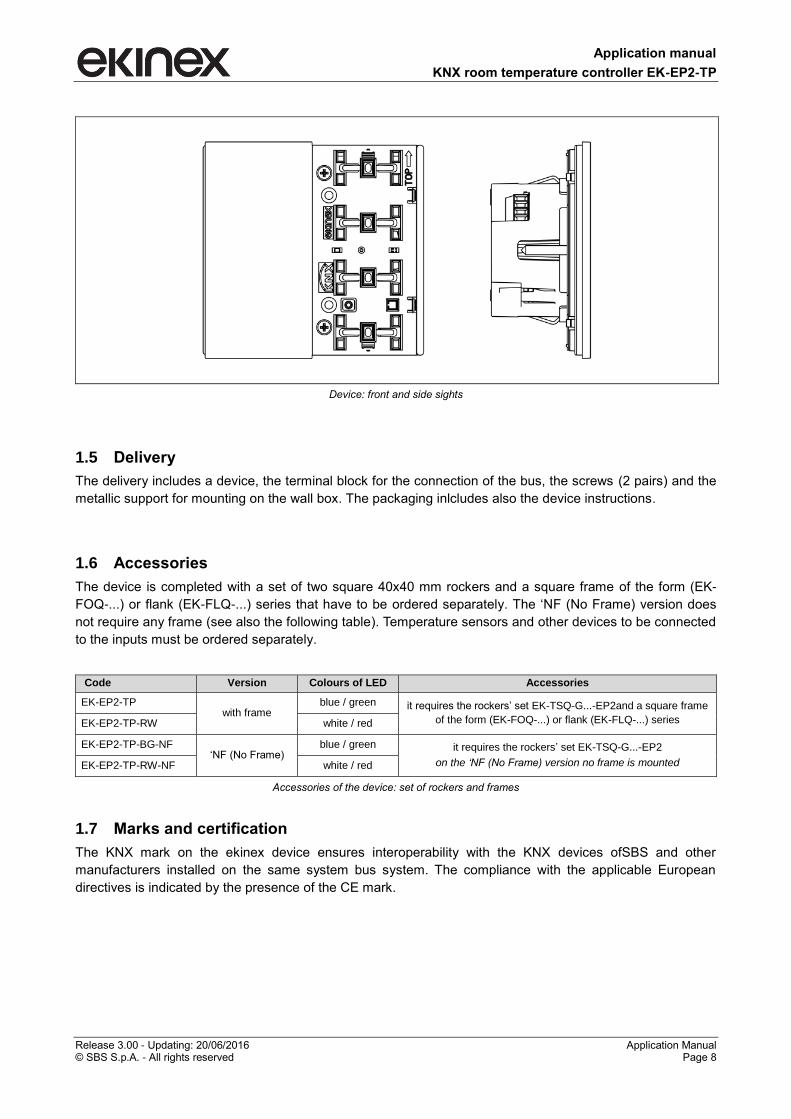
1.4 Design
The device is realised for wall-mounting on round or square wall box with distance between fixing holes of 60
mm. The programming pushbutton and the programming led are on the front side under the rockers. On the
rear side of the housing there is the 4-pole terminal block for the connection of the 2 inputs and the terminal
block for the connection of the bus.
Application manual
KNX room temperature controller EK-EP2-TP
Release 3.00 - Updating: 20/06/2016 Application Manual © SBS S.p.A. - All rights reserved Page 8
Device: front and side sights
1.5 Delivery
The delivery includes a device, the terminal block for the connection of the bus, the screws (2 pairs) and the
metallic support for mounting on the wall box. The packaging inlcludes also the device instructions.
1.6 Accessories
The device is completed with a set of two square 40x40 mm rockers and a square frame of the form (EK-
FOQ-...) or flank (EK-FLQ-...) series that have to be ordered separately. The ‘NF (No Frame) version does
not require any frame (see also the following table). Temperature sensors and other devices to be connected
to the inputs must be ordered separately.
Code Version Colours of LED Accessories
EK-EP2-TP with frame
blue / green it requires the rockers’ set EK-TSQ-G...-EP2and a square frame
of the form (EK-FOQ-...) or flank (EK-FLQ-...) series EK-EP2-TP-RW white / red
EK-EP2-TP-BG-NF ‘NF (No Frame)
blue / green it requires the rockers’ set EK-TSQ-G...-EP2
on the ‘NF (No Frame) version no frame is mounted EK-EP2-TP-RW-NF white / red
Accessories of the device: set of rockers and frames
1.7 Marks and certification
The KNX mark on the ekinex device ensures interoperability with the KNX devices ofSBS and other
manufacturers installed on the same system bus system. The compliance with the applicable European
directives is indicated by the presence of the CE mark.
Application manual
KNX room temperature controller EK-EP2-TP
Release 3.00 - Updating: 20/06/2016 Application Manual © SBS S.p.A. - All rights reserved Page 9
2 Installation
The device has degree of protection IP20, and is therefore suitable for use in dry interior rooms. The
installation of the device requires the following steps:
a) fix the metallic support with the screws supplied on a wall box with distance between fixing holes of
60 mm. It is recommended to install the device at a height of 150 cm;
b) if required, snap a square frame of the form or flank series, inserting it from the rear of the device;
c) connect the sensors or the contacts required to the 4-poles screw terminal block on the rear of the
device;
d) insert the terminal for the bus (red/black), previously connected to the bus cable, in its slot on the
rear side. At this point it is recommended to carry out the commissioning of the device or at least the
download of the physical address;
e) install the device on the metallic support through the spring system, tightening then the two screws
f) requires also to tighten the screws included in the delivery. For mounting the device follow also the
indication TOP (arrow tip pointing up) on the rear side of the device;.
g) snap the two rockers onto the device for the operation of the room temperature controller.
The device can only be mounted on a round or square wall flush mounting box with 60 mm distance between
fixing holes. If necessary, the metallic support for mounting on the wall box can also be ordered separately.
2.1 Connection
For the operation the device has to be connected to the bus line and addressed, configured and
commissioned with ETS (Engineering Tool Software). The connection of one or two sensors to the inputs is
optional and must be defined by the planner of the bus system.
2.1.1 Connection of the bus line
The connection of the KNX bus line is made with the terminal block (red/black) included in delivery and
inserted into the slot of the housing.
Characteristics of the KNX terminal block
• spring clamping of conductors
• 4 seats for conductors for each polarity
• terminal suitable for KNX bus cable with single-wire conductors and diameter between 0.6 and 0.8
mm
• recommended wire stripping approx. 5 mm
• color codification: red = + (positive) bus conductor, black = - (negative) bus conductor
2.1.2 Connection of the inputs
The connection of the inputs is made with the screw terminals located at the rear side of the device. The
maximum cable length is 10 m. For the connection use a cable of max section 1,5 mm². The connection
cable must have sufficient length to allow the extraction of the device from the wall-mounting box.
Characteristics of the terminal blocks for the inputs
• screw clamping of conductors
• maximum cross section of conductor 1 mm² (multiwire)
• recommended wire stripping approx. 5 mm
Application manual
KNX room temperature controller EK-EP2-TP
Release 3.00 - Updating: 20/06/2016 Application Manual © SBS S.p.A. - All rights reserved Page 10
• torque max 0.2 Nm
Connection of the device of the bus line
Bus
KNX
+
–
Application manual
KNX room temperature controller EK-EP2-TP
Release 3.00 - Updating: 20/06/2016 Application Manual © SBS S.p.A. - All rights reserved Page 11
3 Configuration and commissioning
The configuration and commissioning are carried out with the ETS (Engineering Tool Software) tool and the
ekinex® application program provided free of charge by SBS; you do not need any additional software or
plug-in tool. For further information on ETS see also www.knx.org.
3.1 Configuration
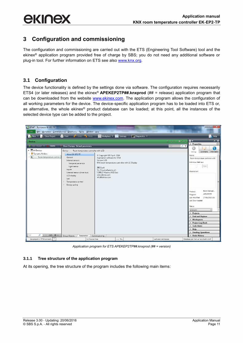
The device functionality is defined by the settings done via software. The configuration requires necessarily
ETS4 (or later releases) and the ekinex® APEKEP2TP##.knxprod (## = release) application program that
can be downloaded from the website www.ekinex.com. The application program allows the configuration of
all working parameters for the device. The device-specific application program has to be loaded into ETS or,
as alternative, the whole ekinex® product database can be loaded; at this point, all the instances of the
selected device type can be added to the project.
Application program for ETS APEKEP2TP##.knxprod (## = version)
3.1.1 Tree structure of the application program
At its opening, the tree structure of the program includes the following main items:
Application manual
KNX room temperature controller EK-EP2-TP
Release 3.00 - Updating: 20/06/2016 Application Manual © SBS S.p.A. - All rights reserved Page 12
About EK-EP2-TP
General
Internal sensors
Inputs
External sensors (from bus)
LCD display
Led
Temperature control
Energy saving
Other items may appear depending on the choices done for the parameters of the folders.
3.1.2 Languages of the application program
The application program is available in four languages: English, Italian, German and French. The language
displayed can be changed in ETS choosing "Settings / Presentation language".
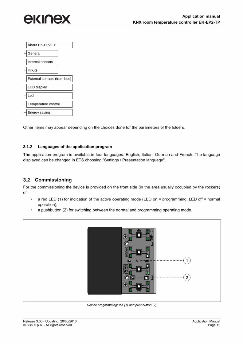
3.2 Commissioning
For the commissioning the device is provided on the front side (in the area usually occupied by the rockers)
of:
• a red LED (1) for indication of the active operating mode (LED on = programming, LED off = normal
operation);
• a pushbutton (2) for switching between the normal and programming operating mode.
Device programming: led (1) and pushbutton (2)
1
2
Application manual
KNX room temperature controller EK-EP2-TP
Release 3.00 - Updating: 20/06/2016 Application Manual © SBS S.p.A. - All rights reserved Page 13
For commissioning the device the following activities are required:
• make the electrical connections; • turn on the bus power supply; • switch the device operation to the programming mode by pressing the
programming pushbutton located on the front side of the housing. In this mode of operation, the programming LED is turned on;
• download into the device the physical address and the configuration with the ETS® program.
When downloading the application program the display shows "PrOg" and the flashing symbol of the clock. At the end of the download the operation of the device automatically returns to normal mode; in this mode the programming LED is turned off. Now the bus device is programmed and ready for use.
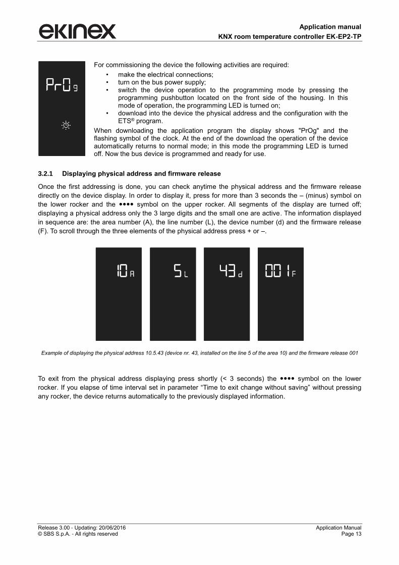
3.2.1 Displaying physical address and firmware release
Once the first addressing is done, you can check anytime the physical address and the firmware release
directly on the device display. In order to display it, press for more than 3 seconds the – (minus) symbol on
the lower rocker and the symbol on the upper rocker. All segments of the display are turned off;
displaying a physical address only the 3 large digits and the small one are active. The information displayed
in sequence are: the area number (A), the line number (L), the device number (d) and the firmware release
(F). To scroll through the three elements of the physical address press + or –.
Example of displaying the physical address 10.5.43 (device nr. 43, installed on the line 5 of the area 10) and the firmware release 001
To exit from the physical address displaying press shortly (< 3 seconds) the symbol on the lower
rocker. If you elapse of time interval set in parameter “Time to exit change without saving” without pressing
any rocker, the device returns automatically to the previously displayed information.
Application manual
KNX room temperature controller EK-EP2-TP
Release 3.00 - Updating: 20/06/2016 Application Manual © SBS S.p.A. - All rights reserved Page 14
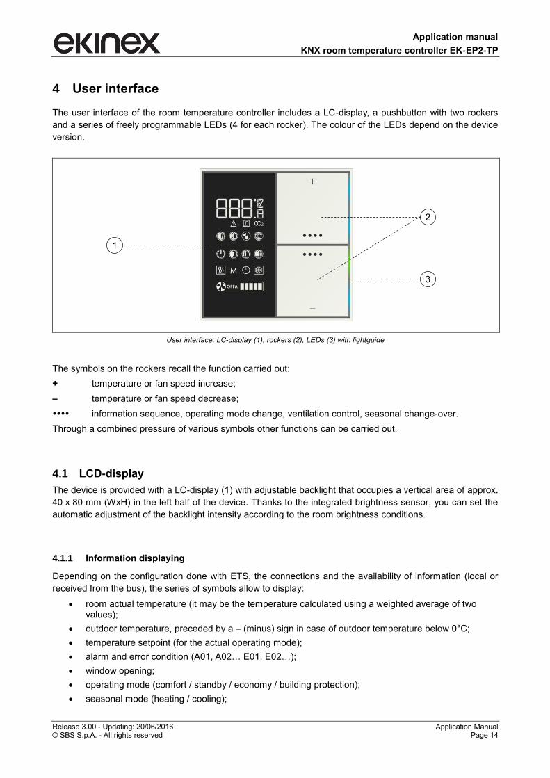
4 User interface
The user interface of the room temperature controller includes a LC-display, a pushbutton with two rockers
and a series of freely programmable LEDs (4 for each rocker). The colour of the LEDs depend on the device
version.
User interface: LC-display (1), rockers (2), LEDs (3) with lightguide
The symbols on the rockers recall the function carried out:
+ temperature or fan speed increase;
‒ temperature or fan speed decrease;
information sequence, operating mode change, ventilation control, seasonal change-over.
Through a combined pressure of various symbols other functions can be carried out.
4.1 LCD-display
The device is provided with a LC-display (1) with adjustable backlight that occupies a vertical area of approx.
40 x 80 mm (WxH) in the left half of the device. Thanks to the integrated brightness sensor, you can set the
automatic adjustment of the backlight intensity according to the room brightness conditions.
4.1.1 Information displaying
Depending on the configuration done with ETS, the connections and the availability of information (local or
received from the bus), the series of symbols allow to display:
room actual temperature (it may be the temperature calculated using a weighted average of two values);
outdoor temperature, preceded by a ‒ (minus) sign in case of outdoor temperature below 0°C;
temperature setpoint (for the actual operating mode);
alarm and error condition (A01, A02… E01, E02…);
window opening;
operating mode (comfort / standby / economy / building protection);
seasonal mode (heating / cooling);
2
1
3
Application manual
KNX room temperature controller EK-EP2-TP
Release 3.00 - Updating: 20/06/2016 Application Manual © SBS S.p.A. - All rights reserved Page 15
device status calling / not calling (or setpoint reached / not reached);
operation in manual mode (M);
operation as slave device (clock);
fan status (1-2-3-automatic-off), when present;
device physical address assigned by ETS.
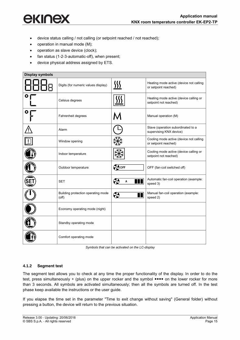
Display symbols
Digits (for numeric values display)
Heating mode active (device not calling
or setpoint reached)
Celsius degrees
Heating mode active (device calling or
setpoint not reached)
Fahrenheit degrees
Manual operation (M)
Alarm
Slave (operation subordinated to a
supervising KNX device)
Window opening
Cooling mode active (device not calling
or setpoint reached)
Indoor temperature
Cooling mode active (device calling or
setpoint not reached)
Outdoor temperature
OFF (fan-coil switched off)
SET
Automatic fan-coil operation (example:
speed 3)
Building protection operating mode
(off)
Manual fan-coil operation (example:
speed 2)
Economy operating mode (night)
Standby operating mode
Comfort operating mode
Symbols that can be activated on the LC-display
4.1.2 Segment test
The segment test allows you to check at any time the proper functionality of the display. In order to do the
test, press simultaneously + (plus) on the upper rocker and the symbol on the lower rocker for more
than 3 seconds. All symbols are activated simultaneously; then all the symbols are turned off. In the test
phase keep available the instructions or the user guide.
If you elapse the time set in the parameter "Time to exit change without saving" (General folder) without
pressing a button, the device will return to the previous situation.

Application manual
KNX room temperature controller EK-EP2-TP
Release 3.00 - Updating: 20/06/2016 Application Manual © SBS S.p.A. - All rights reserved Page 16
4.1.3 Backlight
The backlight intensity of the LC-display is adjustable. The first setting is done when configuring the device
using ETS, but the intensity can be changed later at any time.
To access the change press simultaneously + (plus) and (bothon the upper rocker) for more than 3
seconds. All symbols are turned off except the digits and the percentage symbol. The actual value (as a
percentage) of backlight intensity is displayed. At each pressing of + or – the intensity is increased or
decreased by 5%. To confirm the selected intensity press shortly (< 3 seconds) the symbol either on
the upper rocker. Three rapid flashes of the digits indicate that the new value was saved. If you elapse of
time interval set in the "Time to exit change without saving " (General folder) without pressing any rocker, the
device returns to the previous situation.
4.2 Rockers
The pushbutton with two rockers integrated in the device controls the functions of the thermostat. The set of
two rockers has to be ordered separately; the symbols on the rockers of the set are pre-defined and cannot
be changed. The areas marked by the symbols + (plus) and – (minus) allow you to change a setting (e.g. the
temperature setpoint), while those marked by the symbol ●●●● allow you to display a sequence of
information, to change the operating mode, to control the ventilation, to do the seasonal change-over
(heating to cooling and vice versa) or to confirm a setting change.
The part number of the set EK-TSQ-Gxx-EP2 must be completed with the part (xx) that identifies the
material, color and finishing; for the exact code please refer also to the latest edition of the ekinex product
catalog or the website www.ekinex.com.
Rockers use Upper rocker Lower rocker
Functions for room temperature controlling
+ and
and ‒
Application manual
KNX room temperature controller EK-EP2-TP
Release 3.00 - Updating: 20/06/2016 Application Manual © SBS S.p.A. - All rights reserved Page 17
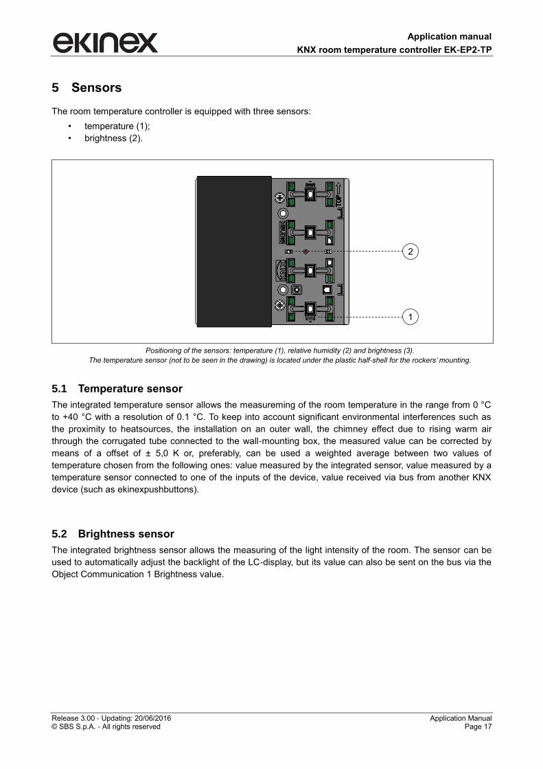
5 Sensors
The room temperature controller is equipped with three sensors:
• temperature (1);
• brightness (2).
Positioning of the sensors: temperature (1), relative humidity (2) and brightness (3).
The temperature sensor (not to be seen in the drawing) is located under the plastic half-shell for the rockers’ mounting.
5.1 Temperature sensor
The integrated temperature sensor allows the measureming of the room temperature in the range from 0 °C
to +40 °C with a resolution of 0.1 °C. To keep into account significant environmental interferences such as
the proximity to heatsources, the installation on an outer wall, the chimney effect due to rising warm air
through the corrugated tube connected to the wall-mounting box, the measured value can be corrected by
means of a offset of ± 5,0 K or, preferably, can be used a weighted average between two values of
temperature chosen from the following ones: value measured by the integrated sensor, value measured by a
temperature sensor connected to one of the inputs of the device, value received via bus from another KNX
device (such as ekinexpushbuttons).
5.2 Brightness sensor
The integrated brightness sensor allows the measuring of the light intensity of the room. The sensor can be
used to automatically adjust the backlight of the LC-display, but its value can also be sent on the bus via the
Object Communication 1 Brightness value.
2
1
Application manual
KNX room temperature controller EK-EP2-TP
Release 3.00 - Updating: 20/06/2016 Application Manual © SBS S.p.A. - All rights reserved Page 18
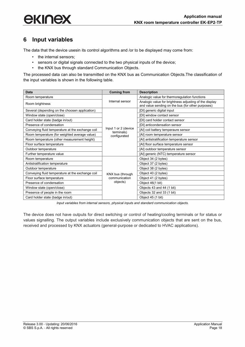
6 Input variables
The data that the device usesin its control algorithms and /or to be displayed may come from:
• the internal sensors;
• sensors or digital signals connected to the two physical inputs of the device;
• the KNX bus through standard Communication Objects.
The processed data can also be transmitted on the KNX bus as Communication Objects.The classification of
the input variables is shown in the following table.
Data Coming from Description
Room temperature
Internal sensor
Analogic value for thermoregulation functions
Room brightness Analogic value for brightness adjusting of the display and value sending on the bus (for other purposes)
Several (depending on the choosen application)
Input 1 or 2 (device terminals)
configurated
[DI] generic digital input
Window state (open/close) [DI] window contact sensor
Card holder state (badge in/out) [DI] card holder contact sensor
Presence of condensation [DI] anticondensation sensor
Conveying fluid temperature at the exchange coil [AI] coil battery temperaure sensor
Room temperature (for weighted average value) [AI] room temperature sensor
Room temperature (other measurement height) [AI] antistratification temperature sensor
Floor surface temperature [AI] floor surface temperature sensor
Outdoor temperature [AI] outdoor temperature sensor
Further temperature value [AI] generic (NTC) temperature sensor
Room temperature
KNX bus (through communication
objects)
Object 34 (2 bytes)
Antistratification temperature Object 37 (2 bytes)
Outdoor temperature Object 38 (2 bytes)
Conveying fluid temperature at the exchange coil Object 40 (2 bytes)
Floor surface temperature Object 41 (2 bytes)
Presence of condensation Object 46(1 bit)
Window state (open/close) Objects 43 and 44 (1 bit)
Presence of people in the room Objects 32 and 33 (1 bit)
Card holder state (badge in/out) Object 45 (1 bit)
Input variables from internal sensors, physical inputs and standard communication objects.
The device does not have outputs for direct switching or control of heating/cooling terminals or for status or
values signalling. The output variables include exclusively communication objects that are sent on the bus,
received and processed by KNX actuators (general-purpose or dedicated to HVAC applications).
Application manual
KNX room temperature controller EK-EP2-TP
Release 3.00 - Updating: 20/06/2016 Application Manual © SBS S.p.A. - All rights reserved Page 19
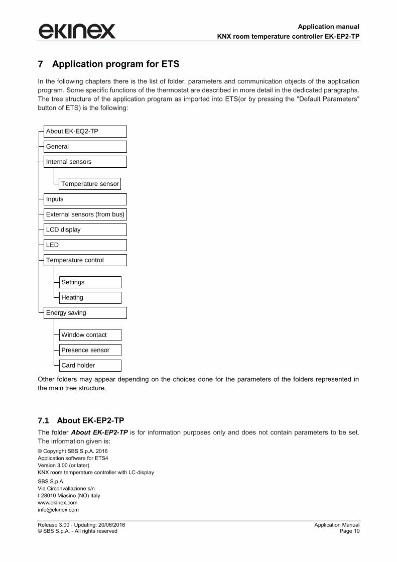
7 Application program for ETS
In the following chapters there is the list of folder, parameters and communication objects of the application
program. Some specific functions of the thermostat are described in more detail in the dedicated paragraphs.
The tree structure of the application program as imported into ETS(or by pressing the "Default Parameters"
button of ETS) is the following:
About EK-EQ2-TP
General
Temperature sensor
Internal sensors
Inputs
External sensors (from bus)
LCD display
LED
Settings
Heating
Temperature control
Window contact
Presence sensor
Card holder
Energy saving
Other folders may appear depending on the choices done for the parameters of the folders represented in
the main tree structure.
7.1 About EK-EP2-TP
The folder About EK-EP2-TP is for information purposes only and does not contain parameters to be set.
The information given is:
© Copyright SBS S.p.A. 2016
Application software for ETS4
Version 3.00 (or later)
KNX room temperature controller with LC-display
SBS S.p.A.
Via Circonvallazione s/n
I-28010 Miasino (NO) Italy
www.ekinex.com
Application manual
KNX room temperature controller EK-EP2-TP
Release 3.00 - Updating: 20/06/2016 Application Manual © SBS S.p.A. - All rights reserved Page 20
7.1.1 General
The General folder includes the following parameters:
Device operation as
Temperature displayed unit
Default displayed information
Time to return to default display information
Button function level
Time to exit change without saving
Delay after bus voltage recovery
The folder has no secondary folders.
7.1.2 Parameters
Parameter name Conditions Values
Device operation as
stand-alone
stand-alone/chrono
slave
If configured as slave, the room temperature controller receives from a KNX device (acting as
supervisor) HVAC modes, setpont values, etc.
Temperature displayed unit Celsius
Fahrenheit
Default displayed information actual temperature
temperature setpoint
The actual temperature is the value by which the device performs the temperature regulation. It
may be the value measured from a single sensor (internal, from the bus or from an input) or
the weighted average of the temperatures measured by a main sensor and an additional
sensor.
The displayed setpoint temperature is that of the operating mode currently set on the room
temperature controller (deduced from the symbol on).
Time to return to default display information
5 s
[other values in the range 10 s … 1 min]
Time interval after which the display automatically switches between the manually recalled
information to the default information.
Button function level end user
system integrator
This parameter allows you to partially disable the functions that can be recalled using the
rockers. The functions that are not enabled if Button function level = end user are the following:
heating / cooling changeover
backlight intensity change
test of display segments
display of physical address and firmware release
Time to exit change without saving 8 s
[other values in the range 2 s … 12 s]
Time interval without further pressing of the rockers at the end of which the device exits the
procedure without saving the current changes.
Delay after bus voltage recovery 00:00:04.000 hh:mm:ss:fff
[range 00:00:04.000 … 00:10:55.350]
Time interval after which the transmission of the telegrams on the bus starts after the power
supply is restored. The delay affects both the event-driven transmission and the cyclic
transmission of a telegram. Regarding the latter, the counting of the pause interval for
retransmission starts at the end of the time of initial delay.
The field has format hh:mm:ss:fff (hours : minutes : seconds .milliseconds): the default value
00:00:04.000 corresponds to 4 seconds.
Application manual
KNX room temperature controller EK-EP2-TP
Release 3.00 - Updating: 20/06/2016 Application Manual © SBS S.p.A. - All rights reserved Page 21
Parameter name Conditions Values
Logic functions disabled / enabled
Enable tab to configure logic functions AND, OR, XOR 8-channel (4 inputs
for channel)
Information displayed as default
One information between the actual temperature and the temperature setpoint is displayed preferably by the
digits of the display. The device allows you to retrieve and display a series of other information pressing the
●●●● symbol on the upper rocker; after the time set in the parameter "Time to return to default information"
without further pressure of ●●●●, the display automatically returns to the default information.
Functional level of the rockers
The use of the rockers for controlling the room temperature controller can be partially inhibited in the
configuration phase through a filter for the access to the several functions. When using the rockers a
distinction is made between:
first level functions (= short or long pressing of the rockers) for the end user;
second level functions (= combination of rockers); to the first level are added a few functions for a
system integrator or an installer.
The enabled functional level is set through a special parameter.
Application manual
KNX room temperature controller EK-EP2-TP
Release 3.00 - Updating: 20/06/2016 Application Manual © SBS S.p.A. - All rights reserved Page 22
7.2 Internal sensors
The Internal sensors folder includes the following parameters:
Temperature sensor
Brightness sensor
7.2.1 Parameters
Parameter name Conditions Values
Temperature sensor enabled
disabled
The temperature sensor is enabled as default.
When the sensor is disabled, the corresponding folder disappears from the
main tree structure of the application program; in this case to have available
again the functions for Temperature control you have to enable Room
temperature in the External sensors (from bus) folder or set Input X = [AI]
temperature sensor (X = 1, 2) in the Inputs folder.
Brightness sensor disabled
enabled
The brightness sensor is disabled as default. When the sensor is enabled,
the corresponding folder appears in the main tree structure of the application
program.
7.2.2 Temperature sensor
The Temperature sensor secondary folder appears only if the corresponding sensor is enabled in the folder
Internal sensors and includes the following parameters:
Filter type
Temperature offset
Minimum change of value to send [K]
Cyclic sending interval
Threshold 1
Threshold 2
7.2.2.1 Parameters and communication objects
Parameter name Conditions Values
Filter type Temperature sensor = enabled
low
medium
high
Low = average value every 4 measurements
Medium = average value every 16 measurements
High = average value every 64 measurements
Temperature offset Temperature sensor = enabled 0°C
[range -5,0°C … +5,0°C]
Minimum change of value to send [K] Temperature sensor = enabled 0,5
[range 0 …5]
If the parameter is set to 0 (zero),no value is sent after a change.
Application manual
KNX room temperature controller EK-EP2-TP
Release 3.00 - Updating: 20/06/2016 Application Manual © SBS S.p.A. - All rights reserved Page 23
Parameter name Conditions Values
Cyclic sending interval Temperature sensor = enabled no sending
[other values in the range 30 s … 120 min]
Threshold 1 Temperature sensor = enabled
not active
below
above
Value [°C] Temperature sensor = enabled,
Threshold 1 = below or above
7
[range 0 … 50]
Threshold 2 Temperature sensor = enabled
not active
below
above
Value [°C] Temperature sensor = enabled,
Threshold 2 = below or above
45
[range 0 … 50]
Hysteresis
Temperature sensor = enabled,
Threshold 1 and/or Threshold 2
= below or above
0,4 K
[other values between 0,2 K and 3 K]
Cyclic sending interval
Temperature sensor = enabled,
Threshold 1 and/or Threshold 2
= below or above
no sending
[other values in the range 30 s … 120 min]
Object name Conditions Dim. Flags DPT Comm.
Obj. No.
Temperature value Temperature sensor = enabled 2 Bytes CR-T-- [9.001]
temperature (°C) 3
Temperature threshold1 - Switch Temperature sensor = enabled,
Threshold 1 = below or above 1 Bit CR-T-- [1.001] switch 16
Temperature threshold 2- Switch Temperature sensor = enabled,
Threshold 2 = below or above 1 Bit CR-T-- [1.001] switch 17
Acquisition filter
The acquisition filter calculates an average with a series of measured values before sending on the bus. The
parameter can have the following values:
low = average value every 4 measurements;
medium = average value every 16 measurements;
high = average value every 64 measurements.
Correction of the measured temperature
The sampling of the temperature value occurs every 10 seconds, while the display is updated every minute.
During the configuration with ETS the opportunity is given to correct the measured temperature value within
the offset range of - 2.5 °C ... + 2.5 °C (step: 0.1 K).
Application manual
KNX room temperature controller EK-EP2-TP
Release 3.00 - Updating: 20/06/2016 Application Manual © SBS S.p.A. - All rights reserved Page 24
7.2.3 Brightness sensor
The Brightness sensor secondary folder appears only if the corresponding sensor is enabled in the folder
Internal sensors and includes the following parameters:
Filter type
Sensor value multiplier (1÷255) x 0,1
Minimum change of value to send [%]
Cyclic sending interval
Threshold 1
Threshold 2
Value [Lux]
Hysteresis
Using the brightness value
The value measured by the brightness sensor integrated in the device may be used for:
sending the value on the KNX bus through a communication object;
automatically adjusting the light intensity emitted by the backlight of the display.
7.2.3.1 Parameters and communication objects
Parameter name Conditions Values
Filter type Brightness sensor = enabled
low
medium
high
Low = average value every 4 measurements
Medium = average value every 16 measurements
High = average value every 64 measurements
Sensor value multiplier (1÷255) x 0,1 Brightness sensor = enabled 10
[other values in the range 1… 255]
Minimum change of value to send [Lux] Brightness sensor = enabled 50
[other values in the range 0 … 670760]
If the parameter is set to 0 (zero), no value is sent after a change.
Cyclic sending interval Brightness sensor = enabled no sending
[other values in the range 30 s … 120 min]
Threshold 1 Brightness sensor = enabled not active / below / above
Value [Lux] Brightness sensor = enabled,
Threshold 1 = below or above
500
[other values in the range 0 … 670760]
Threshold 2 Brightness sensor = enabled not active / below / above
Value [Lux] Brightness sensor = enabled,
Threshold 2 = below or above
500
[other values in the range 0 … 670760]
Hysteresis Threshold 1 = below or above,
Threshold 2 = below or above
50 lux
[other values in the range 5 … 200 Lux]
The value of the parameter Hysteresis is common for both parameters Threshold 1
and Threshold 2.
Application manual
KNX room temperature controller EK-EP2-TP
Release 3.00 - Updating: 20/06/2016 Application Manual © SBS S.p.A. - All rights reserved Page 25
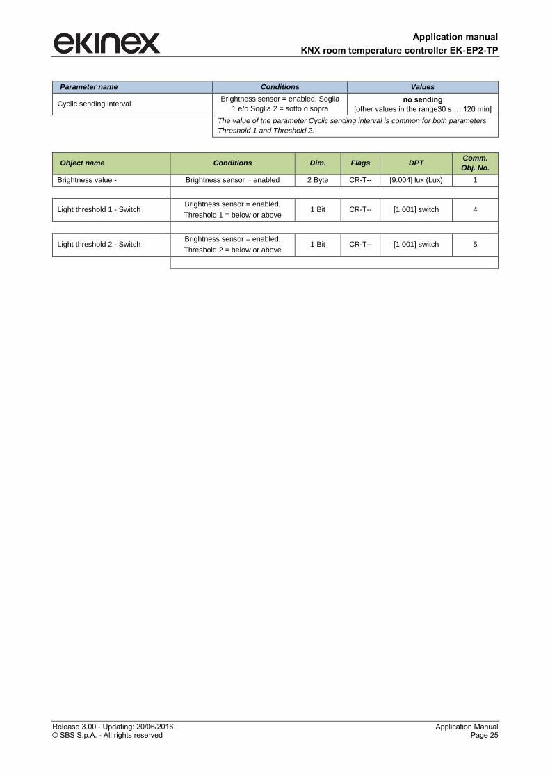
Parameter name Conditions Values
Cyclic sending interval Brightness sensor = enabled, Soglia
1 e/o Soglia 2 = sotto o sopra
no sending
[other values in the range30 s … 120 min]
The value of the parameter Cyclic sending interval is common for both parameters
Threshold 1 and Threshold 2.
Object name Conditions Dim. Flags DPT Comm.
Obj. No.
Brightness value - Brightness sensor = enabled 2 Byte CR-T-- [9.004] lux (Lux) 1
Light threshold 1 - Switch Brightness sensor = enabled,
Threshold 1 = below or above 1 Bit CR-T-- [1.001] switch 4
Light threshold 2 - Switch Brightness sensor = enabled,
Threshold 2 = below or above 1 Bit CR-T-- [1.001] switch 5
Application manual
KNX room temperature controller EK-EP2-TP
Release 3.00 - Updating: 20/06/2016 Application Manual © SBS S.p.A. - All rights reserved Page 26
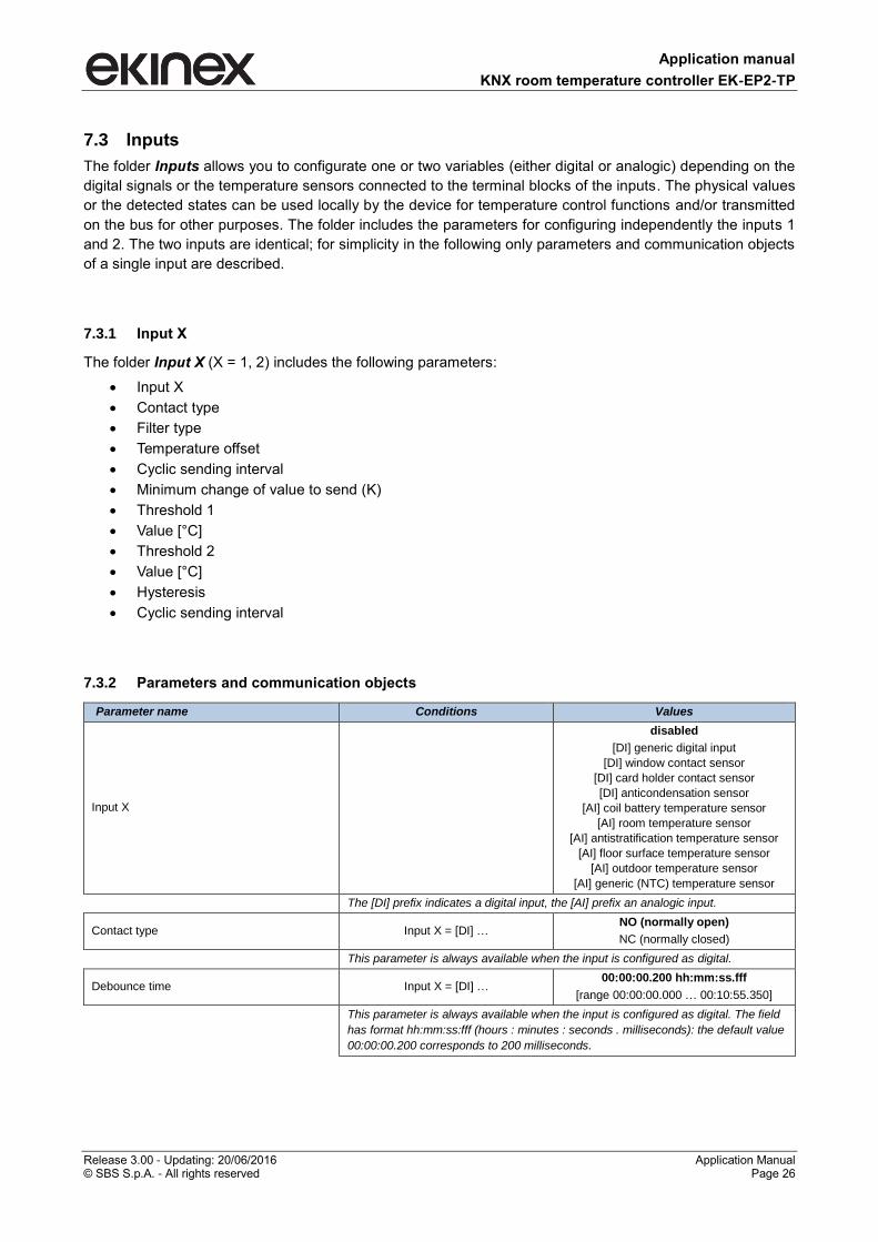
7.3 Inputs
The folder Inputs allows you to configurate one or two variables (either digital or analogic) depending on the
digital signals or the temperature sensors connected to the terminal blocks of the inputs. The physical values
or the detected states can be used locally by the device for temperature control functions and/or transmitted
on the bus for other purposes. The folder includes the parameters for configuring independently the inputs 1
and 2. The two inputs are identical; for simplicity in the following only parameters and communication objects
of a single input are described.
7.3.1 Input X
The folder Input X (X = 1, 2) includes the following parameters:
Input X
Contact type
Filter type
Temperature offset
Cyclic sending interval
Minimum change of value to send (K)
Threshold 1
Value [°C]
Threshold 2
Value [°C]
Hysteresis
Cyclic sending interval
7.3.2 Parameters and communication objects
Parameter name Conditions Values
Input X
disabled
[DI] generic digital input
[DI] window contact sensor
[DI] card holder contact sensor
[DI] anticondensation sensor
[AI] coil battery temperature sensor
[AI] room temperature sensor
[AI] antistratification temperature sensor
[AI] floor surface temperature sensor
[AI] outdoor temperature sensor
[AI] generic (NTC) temperature sensor
The [DI] prefix indicates a digital input, the [AI] prefix an analogic input.
Contact type Input X = [DI] … NO (normally open)
NC (normally closed)
This parameter is always available when the input is configured as digital.
Debounce time Input X = [DI] … 00:00:00.200 hh:mm:ss.fff
[range 00:00:00.000 … 00:10:55.350]
This parameter is always available when the input is configured as digital. The field
has format hh:mm:ss:fff (hours : minutes : seconds . milliseconds): the default value
00:00:00.200 corresponds to 200 milliseconds.
Application manual
KNX room temperature controller EK-EP2-TP
Release 3.00 - Updating: 20/06/2016 Application Manual © SBS S.p.A. - All rights reserved Page 27
Parameter name Conditions Values
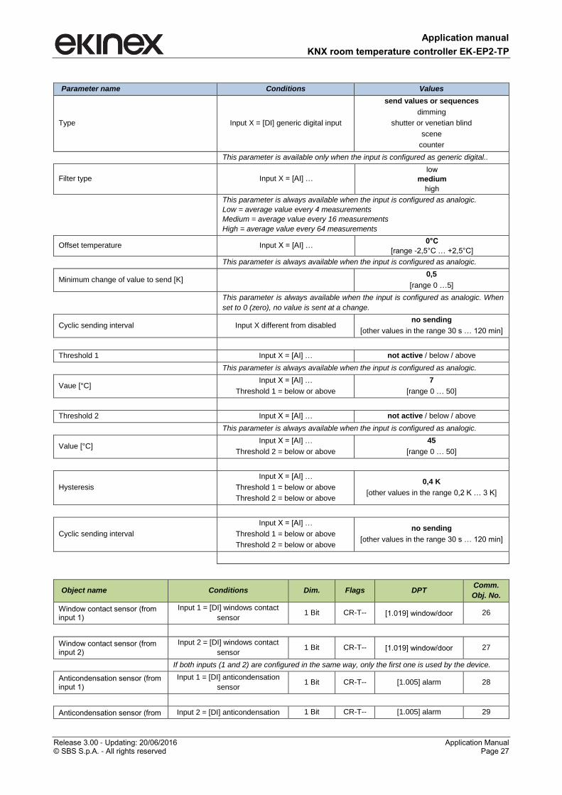
Type Input X = [DI] generic digital input
send values or sequences
dimming
shutter or venetian blind
scene
counter
This parameter is available only when the input is configured as generic digital..
Filter type Input X = [AI] …
low
medium
high
This parameter is always available when the input is configured as analogic.
Low = average value every 4 measurements
Medium = average value every 16 measurements
High = average value every 64 measurements
Offset temperature Input X = [AI] … 0°C
[range -2,5°C … +2,5°C]
This parameter is always available when the input is configured as analogic.
Minimum change of value to send [K] 0,5
[range 0 …5]
This parameter is always available when the input is configured as analogic. When
set to 0 (zero), no value is sent at a change.
Cyclic sending interval Input X different from disabled no sending
[other values in the range 30 s … 120 min]
Threshold 1 Input X = [AI] … not active / below / above
This parameter is always available when the input is configured as analogic.
Vaue [°C] Input X = [AI] …
Threshold 1 = below or above
7
[range 0 … 50]
Threshold 2 Input X = [AI] … not active / below / above
This parameter is always available when the input is configured as analogic.
Value [°C] Input X = [AI] …
Threshold 2 = below or above
45
[range 0 … 50]
Hysteresis
Input X = [AI] …
Threshold 1 = below or above
Threshold 2 = below or above
0,4 K
[other values in the range 0,2 K … 3 K]
Cyclic sending interval
Input X = [AI] …
Threshold 1 = below or above
Threshold 2 = below or above
no sending
[other values in the range 30 s … 120 min]
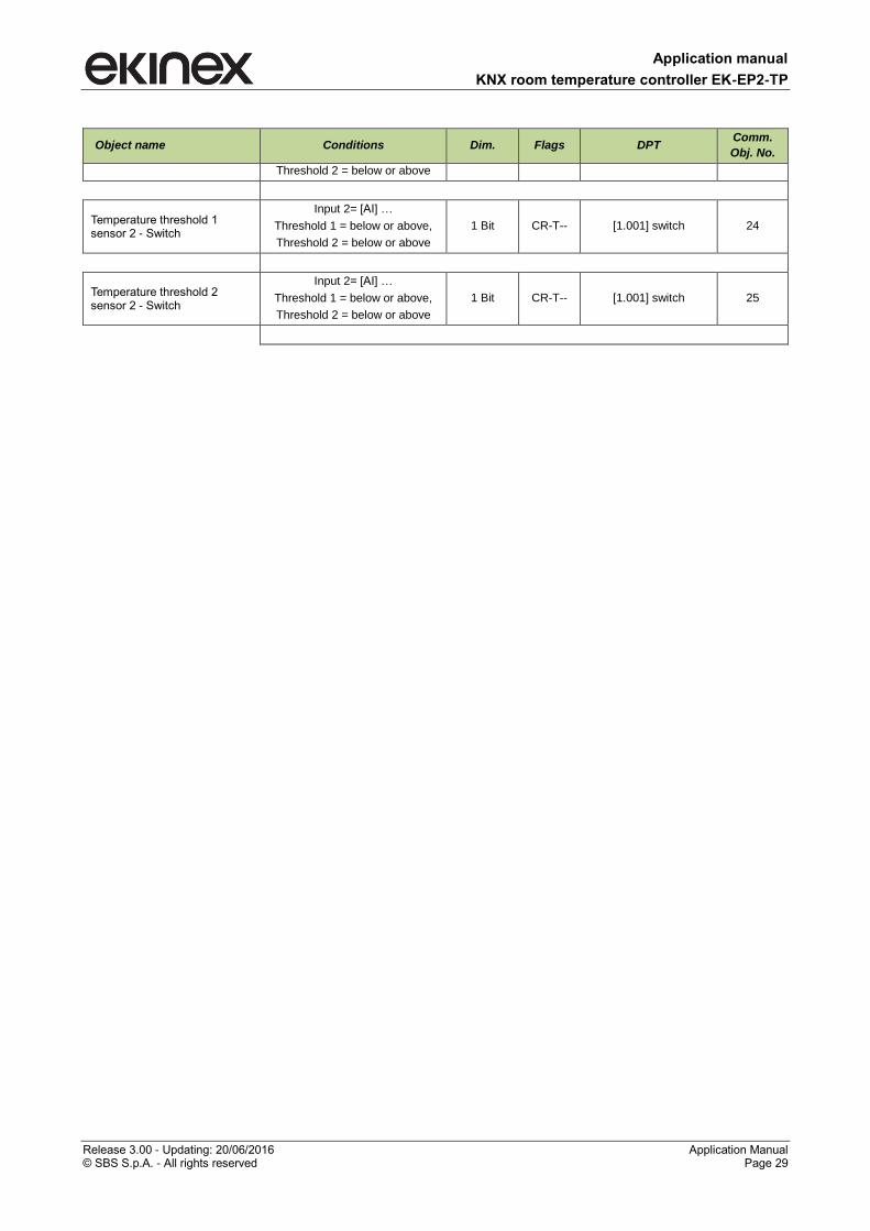
Object name Conditions Dim. Flags DPT Comm.
Obj. No.
Window contact sensor (from input 1)
Input 1 = [DI] windows contact
sensor 1 Bit CR-T-- [1.019] window/door 26
Window contact sensor (from input 2)
Input 2 = [DI] windows contact
sensor 1 Bit CR-T-- [1.019] window/door 27
If both inputs (1 and 2) are configured in the same way, only the first one is used by the device.
Anticondensation sensor (from input 1)
Input 1 = [DI] anticondensation
sensor 1 Bit CR-T-- [1.005] alarm 28
Anticondensation sensor (from Input 2 = [DI] anticondensation 1 Bit CR-T-- [1.005] alarm 29
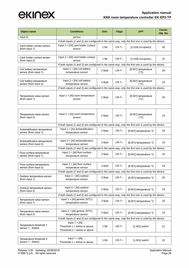
Application manual
KNX room temperature controller EK-EP2-TP
Release 3.00 - Updating: 20/06/2016 Application Manual © SBS S.p.A. - All rights reserved Page 28
Object name Conditions Dim. Flags DPT Comm.
Obj. No.
input 2) sensor
If both inputs (1 and 2) are configured in the same way, only the first one is used by the device.
Card holder contact sensor (from input 1)
Input 1 = [DI] card holder contact
sensor 1 Bit CR-T-- [1.018] occupancy 30
Card holder contact sensor (from input 2)
Input 2 = [DI] card holder contact
sensor 1 Bit CR-T-- [1.018] occupancy 31
If both inputs (1 and 2) are configured in the same way, only the first one is used by the device.
Coil battery temperature sensor (from input 1)
Input 1 = [AI] coil battery
temperature sensor 2 Byte CR-T--
[9.001] temperature (°C)
20
Coil battery temperature sensor (from input 2)
Input 2 = [AI] coil battery
temperature sensor 2 Byte CR-T--
[9.001] temperature (°C)
23
If both inputs (1 and 2) are configured in the same way, only the first one is used by the device.
Temperature value sensor (from input 1)
Input 1 = [AI] room temperature
sensor 2 Byte CR-T--
[9.001] temperature (°C)
20
Temperature value sensor (from input 2)
Input 2 = [AI] room temperature
sensor 2 Byte CR-T--
[9.001] temperature (°C)
23
If both inputs (1 and 2) are configured in the same way, only the first one is used by the device.
Antistratification temperature sensor (from input 1)
Input 1 = [AI] antistratification
temperature sensor 2 Byte CR-T-- [9.001] temperature °C 20
Antistratification temperature sensor (from input 2)
Input 2 = [AI] antistratification
temperature sensor 2 Byte CR-T-- [9.001] temperature °C 23
If both inputs (1 and 2) are configured in the same way, only the first one is used by the device.
Floor surface temperature sensor (from input 1)
Input 1 = [AI] floor surface
temperature sensor 2 Byte CR-T-- [9.001] temperature °C 20
Floor surface temperature sensor (from input 2)
Input 2 = [AI] floor surface
temperature sensor 2 Byte CR-T-- [9.001] temperature °C 23
If both inputs (1 and 2) are configured in the same way, only the first one is used by the device.
Outdoor temperature sensor (from input 1)
Input 1 = [AI] outdoor
temperature sensor 2 Byte CR-T-- [9.001] temperature °C 20
Outdoor temperature sensor (from input 2)
Input 2 = [AI] outdoor
temperature sensor 2 Byte CR-T-- [9.001] temperature °C 23
If both inputs (1 and 2) are configured in the same way, only the first one is used by the device.
Temperature value sensor (from input 1)
Input 1 = [AI] generic (NTC)
temperature sensor 2 Byte CR-T-- [9.001] temperature °C 20
Temperature value sensor (from input 2)
Input 2 = [AI] generic (NTC)
temperature sensor 2 Byte CR-T-- [9.001] temperature °C 23
If both inputs (1 and 2) are configured in the same way, only the first one is used by the device.
Temperature threshold 1 sensor 1 - Switch
Input 1 = [AI] …
Threshold 1 = below or above,
Threshold 2 = below or above
1 Bit CR-T-- [1.001] switch 21
Temperature threshold 2 sensor 1 - Switch
Input 1 = [AI] …
Threshold 1 = below or above, 1 Bit CR-T-- [1.001] switch 22
Application manual
KNX room temperature controller EK-EP2-TP
Release 3.00 - Updating: 20/06/2016 Application Manual © SBS S.p.A. - All rights reserved Page 29
Object name Conditions Dim. Flags DPT Comm.
Obj. No.
Threshold 2 = below or above
Temperature threshold 1 sensor 2 - Switch
Input 2= [AI] …
Threshold 1 = below or above,
Threshold 2 = below or above
1 Bit CR-T-- [1.001] switch 24
Temperature threshold 2 sensor 2 - Switch
Input 2= [AI] …
Threshold 1 = below or above,
Threshold 2 = below or above
1 Bit CR-T-- [1.001] switch 25
Application manual
KNX room temperature controller EK-EP2-TP
Release 3.00 - Updating: 20/06/2016 Application Manual © SBS S.p.A. - All rights reserved Page 30
7.4 External sensors (from bus)
As “external sensors” are intended KNX-devices (or conventional sensors interfaced to the bus through KNX
devices) which send states or values to the room temperature controller via the bus. Enabling an external
sensor, without connecting the corresponding communication object, generates a permanent alarm on the
display and suspends the thermoregulation function.
The folder External sensors (from bus) includes the following parameters:
Room temperature
Antistratification temperature
Outdoor temperature
Floor surface temperature
Anticondensation
Window contact X (X = 1, 2)
Presence sensor X (X = 1, 2)
Card holder contact
Analog sensor timeout
Digital sensor timeout
The folder does not have any secondary folder.
7.4.1 Parameters and communication objects
Parameter name Conditions Values
Room temperature disabled / enabled
It enables a bus temperature sensor. The measured value can be used to
calculate a weighted average value in combination with the temperature
sensor integrated into the device or a temperature sensor connected to a
device input.
Antistratification temperature disabled / enabled
It enables a temperature bus sensor to carry out the antistratification function.
Outdoor temperature disabled / enabled
It enables an outdoor temperature bus sensor to display the measured value
on the display. This is alternative to an outdoor temperature sensor connected
to a device input: the parameter appears only if the external temperature
sensor is disabled in the Inputs folder.
Air quality disabled / enabled
It enables an air quality bus sensor to display the measured value (CO2
concentration) on the display.
Coil temperature disabled / enabled
It enables a bus sensor for measuring the conveying fluid temperature at the
coil for heat exchange. The acquisition of the value allows realizing the hot-
start function of a fan.
Floor surface temperature disabled / enabled
It enables a bus sensor for measuring the surface temperature of a floor
heating system. The acquisition of the value allows to realize the function of
surface temperature limitation.
Analogic sensors timeout 00:05:00hh:mm:ss
[range 00:00:00 … 18:12:15]
The field has format hh:mm:ss (hours : minutes : seconds): the default value
00:05:00 corresponds to a timeout of 5 minutes. The value 00:00:00 means
that the timeout of the analogic sensors is disabled.
Application manual
KNX room temperature controller EK-EP2-TP
Release 3.00 - Updating: 20/06/2016 Application Manual © SBS S.p.A. - All rights reserved Page 31
Parameter name Conditions Values
Anticondensation disabled / enabled
It enables a bus sensor for detecting the condensation.
Window contact 1 disabled / enabled
It enables a bus sensor for detecting the state of opening / closing of a window
or a door.
Window contact 2 disabled / enabled
It enables a bus sensor for detecting the state of opening / closing of a window
or a door.
Presence sensor 1 disabled / enabled
It enables a bus sensor for detecting the presence / absence of people within a
room.
Presence sensor 2 disabled / enabled
It enables a bus sensor for detecting the presence / absence of people within a
room.
Card holder contact disabled / enabled
It enables a bus sensor for detecting the presence / absence of people in a
hotel room provided with a card holder.
Digital sensors timeout 00:05:00hh:mm:ss
[range 00:00:00 … 18:12:15]
The field has format hh:mm:ss (hours : minutes : seconds): the default value
00:05:00 corresponds to a timeout of 5 minutes. The value 00:00:00 means
that the timeout of the digital sensors is disabled.
Object name Conditions Dim. Flags DPT Comm. Obj.
No.
Room temperature (from bus) enabled 2 Byte C-W--- [9.001]
temperature (°C) 34
Antistratification temperature (from bus)
enabled 2 Byte C-W--- [9.001]
temperature (°C) 37
Outdoor temperature (from bus) enabled 2 Byte C-W--- [9.001]
temperature °C 38
Coil temperature (from bus) enabled 2 Byte C-W--- [9.001]
temperature (°C) 40
Floor temperature (from bus) enabled 2 Byte C-W--- [9.001]
temperature (°C) 41
Anticondensation (from bus) enabled 1 Bit C-W--- [1.001] switch 46
Windows contact sensor 1 (from bus)
enabled 1 Bit C-W--- [1.019]
window/door 43
Windows contact sensor 2 (from bus)
enabled 1 Bit C-W--- [1.019]
window/door 44
Presence sensor 1 (from bus) enabled 1 Bit C-W--- [1.018] occupancy 32
Presence sensor 2 (from bus) enabled 1 Bit C-W--- [1.018] occupancy 33
Contact of card holder (from bus) enabled 1 Bit C-W--- [1.001] switch 45
Application manual
KNX room temperature controller EK-EP2-TP
Release 3.00 - Updating: 20/06/2016 Application Manual © SBS S.p.A. - All rights reserved Page 32
About the sensor timeout
The system of internal control of the thermostat monitors cyclically the updating status of the values of the
external sensors (from bus) and the inputs when the timeout setting expires. In case no updated value has
been received, the regulation function is suspended, an alarm is displayed on the display through the symbol
and the corresponding alarm code (see also the list of alarms in the paragraph Diagnostics).
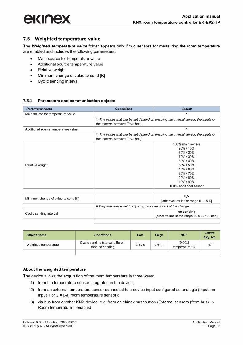
Application manual
KNX room temperature controller EK-EP2-TP
Release 3.00 - Updating: 20/06/2016 Application Manual © SBS S.p.A. - All rights reserved Page 33
7.5 Weighted temperature value
The Weighted temperature value folder appears only if two sensors for measuring the room temperature
are enabled and includes the following parameters:
Main source for temperature value
Additional source temperature value
Relative weight
Minimum change of value to send [K]
Cyclic sending interval
7.5.1 Parameters and communication objects
Parameter name Conditions Values
Main source for temperature value *
*) The values that can be set depend on enabling the internal sensor, the inputs or
the external sensors (from bus).
Additional source temperature value *
*) The values that can be set depend on enabling the internal sensor, the inputs or
the external sensors (from bus).
Relative weight
100% main sensor
90% / 10%
80% / 20%
70% / 30%
60% / 40%
50% / 50%
40% / 60%
30% / 70%
20% / 80%
10% / 90%
100% additional sensor
Minimum change of value to send [K] 0,5
[other values in the range 0 … 5 K]
If the parameter is set to 0 (zero), no value is sent at the change.
Cyclic sending interval no sending
[other values in the range 30 s … 120 min]
Object name Conditions Dim. Flags DPT Comm.
Obj. No.
Weighted temperature Cyclic sending interval different
than no sending 2 Byte CR-T--
[9.001]
temperature °C 47
About the weighted temperature
The device allows the acquisition of the room temperature in three ways:
1) from the temperature sensor integrated in the device;
2) from an external temperature sensor connected to a device input configured as analogic (Inputs
Input 1 or 2 = [AI] room temperature sensor);
3) via bus from another KNX device, e.g. from an ekinex pushbutton (External sensors (from bus)
Room temperature = enabled);
Application manual
KNX room temperature controller EK-EP2-TP
Release 3.00 - Updating: 20/06/2016 Application Manual © SBS S.p.A. - All rights reserved Page 34
To optimize or correct the room temperature regulation in special cases (in large rooms, in presence of
strong asymmetry of the temperature distribution, when the installation of the device is in a position not
suitable, etc.), the device can then use a weighted average between two temperature values. The weights
are assigned by the parameter Relative weight that assigns a ratio of the two values.
Application manual
KNX room temperature controller EK-EP2-TP
Release 3.00 - Updating: 20/06/2016 Application Manual © SBS S.p.A. - All rights reserved Page 35
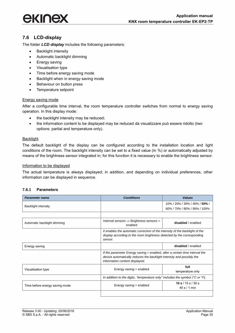
7.6 LCD-display
The folder LCD display includes the following parameters:
Backlight intensity
Automatic backlight dimming
Energy saving
Visualisation type
Time before energy saving mode
Backlight when in energy saving mode
Behaviour on button press
Temperature setpoint
Energy saving mode
After a configurable time interval, the room temperature controller switches from normal to energy saving
operation. In this display mode:
the backlight intensity may be reduced;
the information content to be displayed may be reduced da visualizzare può essere ridotto (two
options: partial and temperature only).
Backlight
The default backlight of the display can be configured according to the installation location and light
conditions of the room. The backlight intensity can be set to a fixed value (in %) or automatically adjusted by
means of the brightness sensor integrated in; for this function it is necessary to enable the brightness sensor.
Information to be displayed
The actual temperature is always displayed; in addition, and depending on individual preferences, other
information can be displayed in sequence.
7.6.1 Parameters
Parameter name Conditions Values
Backlight intensity 10% / 20% / 30% / 40% / 50% /
60% / 70% / 80% / 90% / 100%
Automatic backlight dimming Internal sensors Brightness sensors =
enabled disabled / enabled
It enables the automatic correction of the intensity of the backlight of the
display according to the room brightness detected by the corresponding
sensor.
Energy saving disabled / enabled
If the parameter Energy saving = enabled, after a certain time interval the
device automatically reduces the backlight intensity and possibly the
information content displayed.
Visualisation type Energy saving = enabled full
temperature only
In addition to the digits, “temperature only” includes the symbol (°C or °F).
Time before energy saving mode Energy saving = enabled 10 s / 15 s / 30 s
45 s / 1 min
Application manual
KNX room temperature controller EK-EP2-TP
Release 3.00 - Updating: 20/06/2016 Application Manual © SBS S.p.A. - All rights reserved Page 36
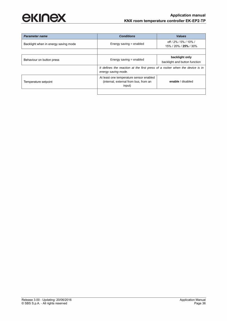
Parameter name Conditions Values
Backlight when in energy saving mode Energy saving = enabled off / 2% / 5% / 10% /
15% / 20% / 25% / 30%
Behaviour on button press Energy saving = enabled backlight only
backlight and button function
It defines the reaction at the first press of a rocker when the device is in
energy saving mode.
Temperature setpoint
At least one temperature sensor enabled
(internal, external from bus, from an
input)
enable / disabled
Application manual
KNX room temperature controller EK-EP2-TP
Release 3.00 - Updating: 20/06/2016 Application Manual © SBS S.p.A. - All rights reserved Page 37
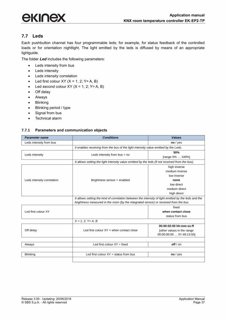
7.7 Leds
Each pushbutton channel has four programmable leds; for example, for status feedback of the controlled
loads or for orientation nightlight. The light emitted by the leds is diffused by means of an appropriate
lightguide.
The folder Led includes the following parameters:
Leds intensity from bus
Leds intensity
Leds intensity correlation
Led first colour XY (X = 1, 2; Y= A, B)
Led second colour XY (X = 1, 2; Y= A, B)
Off delay
Always
Blinking
Blinking period / type
Signal from bus
Technical alarm
7.7.1 Parameters and communication objects
Parameter name Conditions Values
Leds intensity from bus no / yes
It enables receiving from the bus of the light intensity value emitted by the Leds.
Leds intensity Leds intensity from bus = no 50%
[range 0% … 100%]
It allows setting the light intensity value emitted by the leds (if not received from the bus).
Leds intensity correlation Brightness sensor = enabled
high inverse
medium inverse
low inverse
none
low direct
medium direct
high direct
It allows setting the kind of correlation between the intensity of light emitted by the leds and the
brightness measured in the room (by the integrated sensor) or received from the bus.
Led first colour XY
fixed
when contact close
status from bus
X = 1, 2; Y= A, B
Off delay Led first colour XY = when contact close
00:00:02:00 hh:mm:ss:ff
[other values in the range
00:00:00:00 … 01:49:13:50]
Always Led first colour XY = fixed off / on
Blinking Led first colour XY = status from bus no / yes
Application manual
KNX room temperature controller EK-EP2-TP
Release 3.00 - Updating: 20/06/2016 Application Manual © SBS S.p.A. - All rights reserved Page 38
Parameter name Conditions Values
Blinking period / type Led first colour XY = status from bus,
Blinking = yes
0,25 s on / 0,25 s off
0,25 s on / 0,75 s off
0,5 s on / 0,5 s off
0,75 s on / 0,25 s off
0,5 s on / 1,5 s off
1 s on / 1 s off
1,5 s on / 0,5 s off
1 s on / 3 s off
2 s on / 2 s off
3 s on / 1 s off
Signal from bus Led first colour XY = status from bus not inverted / inverted
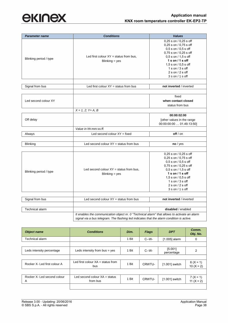
Led second colour XY
fixed
when contact closed
status from bus
X = 1, 2; Y= A, B
Off delay
00:00:02:00
[other values in the range
00:00:00:00 … 01.49.13:50]
Value in hh:mm:ss:ff.
Always Led second colour XY = fixed off / on
Blinking Led second colour XY = status from bus no / yes
Blinking period / type Led second colour XY = status from bus,
Blinking = yes
0,25 s on / 0,25 s off
0,25 s on / 0,75 s off
0,5 s on / 0,5 s off
0,75 s on / 0,25 s off
0,5 s on / 1,5 s off
1 s on / 1 s off
1,5 s on / 0,5 s off
1 s on / 3 s off
2 s on / 2 s off
3 s on / 1 s off
Signal from bus Led second colour XY = status from bus not inverted / inverted
Technical alarm disabled / enabled
It enables the communication object nr. 0 "Technical alarm" that allows to activate an alarm
signal via a bus telegram. The flashing led indicates that the alarm condition is active.
Object name Conditions Dim. Flags DPT Comm.
Obj. No.
Technical alarm 1 Bit C--W- [1.005] alarm 0
Leds intensity percentage Leds intensity from bus = yes 1 Bit C--W- [5.001]
percentage 2
Rocker X- Led first colour A Led first colour XA = status from
bus 1 Bit CRWTU- [1.001] switch
6 (X = 1)
10 (X = 2)
Rocker X- Led second colour
A
Led second colour XA = status
from bus 1 Bit CRWTU- [1.001] switch
7 (X = 1)
11 (X = 2)
Application manual
KNX room temperature controller EK-EP2-TP
Release 3.00 - Updating: 20/06/2016 Application Manual © SBS S.p.A. - All rights reserved Page 39
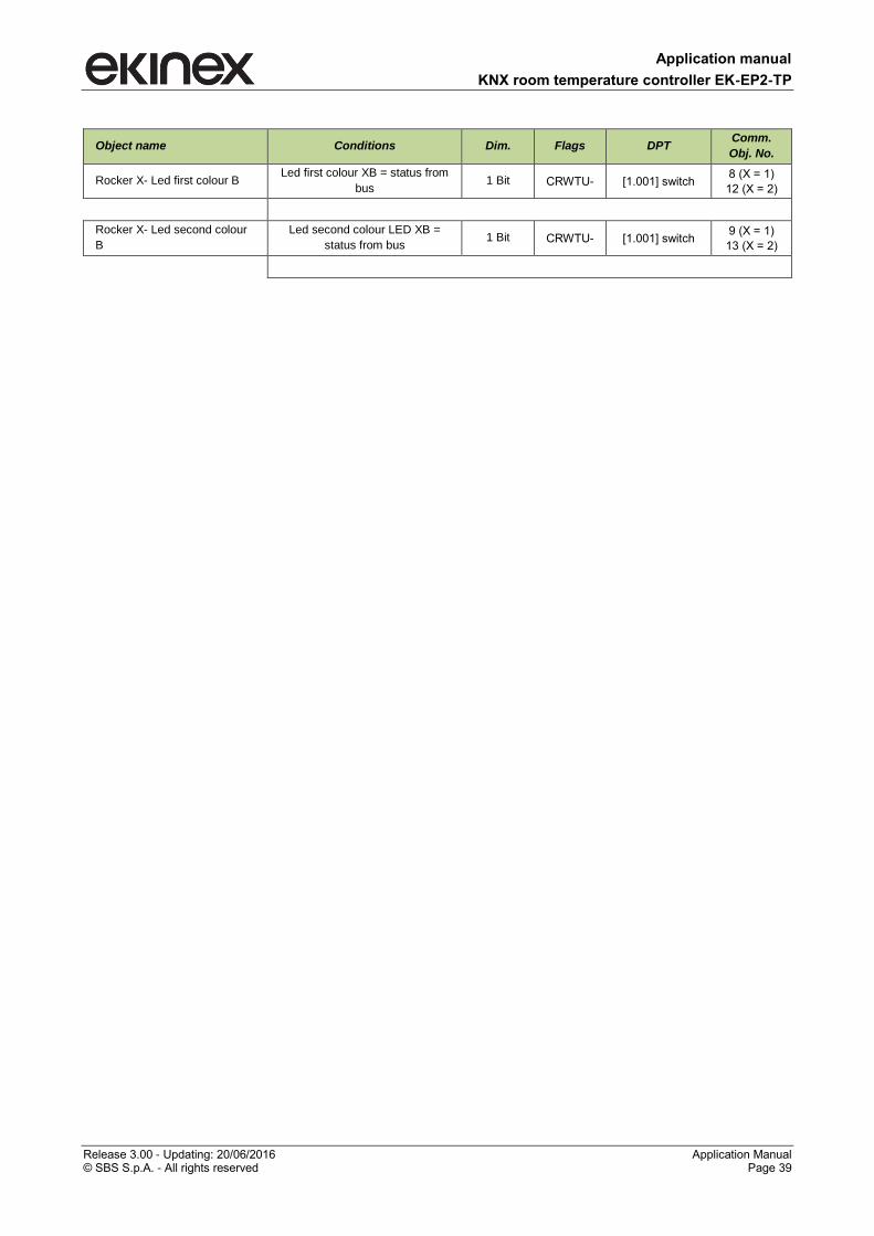
Object name Conditions Dim. Flags DPT Comm.
Obj. No.
Rocker X- Led first colour B Led first colour XB = status from
bus 1 Bit CRWTU- [1.001] switch
8 (X = 1)
12 (X = 2)
Rocker X- Led second colour
B
Led second colour LED XB =
status from bus 1 Bit CRWTU- [1.001] switch
9 (X = 1)
13 (X = 2)
Application manual
KNX room temperature controller EK-EP2-TP
Release 3.00 - Updating: 20/06/2016 Application Manual © SBS S.p.A. - All rights reserved Page 40
7.8 Temperature control
The Temperature control folder includes the following secondary folders:
Settings
Heating
Cooling
Ventilation
Scenes
The Cooling and Ventilation secondary folders appear only if in the Settings folder the parameter
Thermostat function is set to the value both heating and cooling or cooling.
The Scenes secondary folder appears only if in the Settings secondary folder the parameter Scenes is set
to the value enabled.
7.8.1 Settings
The Settings folder includes the following parameters:
Thermostat function
Command Communication Object
Heating – cooling switchover
Setpoint Cyclic sending interval
Max manual temperature change
Saving timeout (manual change)
End of manual operation
Max setpoint temperature change
Scenes
Valve protection function
Frequency
Time interval
7.8.1.1 Parameters and communication objects
Parameter name Conditions Values
Thermostat function
heating
cooling
both heating and cooling
Command Communication Object Thermostat function = both
heating and cooling separated / unique
Heating – cooling switchover Thermostat function = both
heating and cooling
manual
from bus
automatic
Heating-cooling switchover cyclic sending
interval
Thermostat function = both
heating and cooling
no sending
[other values in the range 30 s … 120 min]
Application manual
KNX room temperature controller EK-EP2-TP
Release 3.00 - Updating: 20/06/2016 Application Manual © SBS S.p.A. - All rights reserved Page 41
Parameter name Conditions Values
Setpoint cyclic sending interval no sending
[other values in the range 30 s … 120 min]
The setpoint value that can be sent cyclically is the actual one, depending on the
operating mode set manually by the user or automatically by another KNX
supervising device with the possibility of time scheduling. The actual setpoint value
takes also into account the actual state of the contacts window and presence
detection (if the corresponding functions are enabled).
Max manual temperature change not allowed, ± 1°C, ± 2°C, ± 3°C, ± 4°C, ±
5°C, ± 6°C, ± 7°C, ± 8°C, ± 9°C, ± 10°C
It defines the maximum range allowed for the manual change of the temperature
value.
Saving timeout (manual change) 6 s
[other values in the range 2s … 12 s]
It defines the time interval to wait for a confirmation of a manual change (see
previous parameter). If the time interval elapses without confirmation, the device
automatically returns to the previous state without saving the change.
End of manual operation General Device operation as =
stand-alone
till first telegram from bus
[other values in the range 30 min … 48 h]
Max setpoint temperature change not allowed, ± 1°C, ± 2°C, ± 3°C, ± 4°C, ±
5°C, ± 6°C, ± 7°C, ± 8°C, ± 9°C, ± 10°C
It defines the maximum time allowed for changing the values of temperature
setpoint in the several operating modes.
Scenes disabled / enabled
Valve protection function disabled / enabled
It enables the function that activates the drive for the valve control during periods
of inactivity of the system.
Frequency Valve protection function =
enabled
once a day
once a week
once a month
Time interval Valve protection function =
enabled
10 s
[other values in the range 5 s … 20 min]
Nome oggetto Conditions Dim. Flags DPT
Comm.
Obj.
No.
Actual setpoint 2 Byte CR-T-- [9.001] temperature (°C) 52
Heating/cooling status out Always visible 1 Bit CR-T-- [1.100] heating/cooling 48
The communication object is updated on the bus on event of change internally elaborated by the
controller. The object is always exposed and contains the information about the current conduction
mode of the internal temperature controller.
0 = Cool
[1.100] DPT Heat/Cool 1 Bit
1 = Heating
Application manual
KNX room temperature controller EK-EP2-TP
Release 3.00 - Updating: 20/06/2016 Application Manual © SBS S.p.A. - All rights reserved Page 42
Nome oggetto Conditions Dim. Flags DPT
Comm.
Obj.
No.
Heating/cooling status in
Thermostat function
= both heating and
cooling;
Heating – cooling
switchover = from
bus
1 Bit C-W--- [1.100] heating/cooling 49
The communication object is received by the bus. All’evento di commutazione i regolatori interni
degli stadi primario e ausiliario (se abilitato) commutano il modo di conduzione. Il modo di
conduzione attivo è segnalato dall’apposito simbolo sul display.
HVAC mode in 1 Byte C-W--- [20.102] HVAC mode 50
The device receives the operating mode (HVAC mode) from a bus device with function of
supervisor. The operating mode received through this communication object can be later modified
by the user (in questo caso il termostato ambiente passa in controllo manuale).
HVAC forced mode in 1 Byte C-W--- [20.102] HVAC mode 51
L’oggetto di comunicazione permette di ricevere il modo operativo analogamente a quanto accade
conl’oggetto di comunicazione Modo HVAC in; la differenza è che il modo operativo ricevuto
tramite questo oggetto (ad eccezione del comando AUTO) non può essere successivamente
modificato dall’utente. L’utente può modificare il modo solamente dopo che il Modo HVAC forzato
in ha inviato il comando AUTO.
HVAC mode out 1 Byte CR-T-- [20.102] HVAC mode 83
HVAC manual mode
General Device
operation as =
stand-alone/chrono
1 Byte C-WTU- [20.102] HVAC mode 53
Chrono active status
General Device
operation as =
stand-alone/chrono
1 Bit CR-T-- [1.011] state 54
Manual setpoint 2 Byte C-W--- [9.001] temperature (°C) 55
Manual/forced setpoint active
status 1 Bit CRWTU- [1.011] state 56
Application manual
KNX room temperature controller EK-EP2-TP
Release 3.00 - Updating: 20/06/2016 Application Manual © SBS S.p.A. - All rights reserved Page 43
About the heating/cooling terminals
The application functions of the room temperature controller configurable with ETS are particularly suitable
for the control through general-purpose or dedicated KNX actuators of the following heating/cooling
terminals:
• radiators;
• elettrical heaters;
• fancoils;
• radiant panels;
• dehumidification units;
• radiant panels + radiators (as auxiliary system);
• radiant panels + fancoils (as auxiliary system);
• radiant panels + dehumidification units.
7.8.1.2 Heating/cooling switchover
The switchover between the two seasonal modes (heating / cooling) may happens as follows:
1) manually on the device by the end user;
2) automatically by the device;
3) from the KNX bus through a dedicated communication object.
Manual switch-over (mode 1)
The manual switch-over is suitable for bus systems with one or a limited number of room temperature
controllers. If the devices have been configured for this purpose, the user does the switch-over manually on
the device (that acts as a "master" for the switch-over function); the device sends on the bus the output
communication object [DPT 1.100 heat/cool] that switches possibly other room temperature controllers
("slave" devices) connected through a dedicated group address.
Automatic switch-over (mode 2)
The automatic switch-over is suitable for a 4-pipe hydraulic configuration of the heating/cooling installation
(used e.g. for fan-coil units or ceiling radianti panels). Also in this case the information can be sent on the
bus with the output communication object [DPT 1.100 heat/cool]; the difference from the first mode is that
switching is performed automatically on the basis of a comparison between the values of the actual
temperature and the setpoint temperature. In this mode, the manual switching by the user is disabled.
The automatic switch-over is realised with the introduction of a neutral zone according to the scheme in the
picture below.
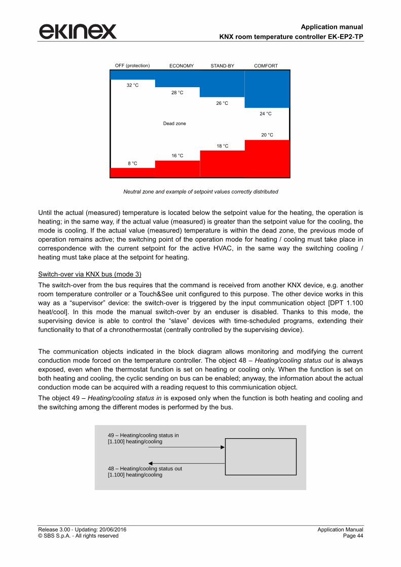
Application manual
KNX room temperature controller EK-EP2-TP
Release 3.00 - Updating: 20/06/2016 Application Manual © SBS S.p.A. - All rights reserved Page 44
Neutral zone and example of setpoint values correctly distributed
Until the actual (measured) temperature is located below the setpoint value for the heating, the operation is
heating; in the same way, if the actual value (measured) is greater than the setpoint value for the cooling, the
mode is cooling. If the actual value (measured) temperature is within the dead zone, the previous mode of
operation remains active; the switching point of the operation mode for heating / cooling must take place in
correspondence with the current setpoint for the active HVAC, in the same way the switching cooling /
heating must take place at the setpoint for heating.
Switch-over via KNX bus (mode 3)
The switch-over from the bus requires that the command is received from another KNX device, e.g. another
room temperature controller or a Touch&See unit configured to this purpose. The other device works in this
way as a “supervisor” device: the switch-over is triggered by the input communication object [DPT 1.100
heat/cool]. In this mode the manual switch-over by an enduser is disabled. Thanks to this mode, the
supervising device is able to control the “slave” devices with time-scheduled programs, extending their
functionality to that of a chronothermostat (centrally controlled by the supervising device).
The communication objects indicated in the block diagram allows monitoring and modifying the current
conduction mode forced on the temperature controller. The object 48 – Heating/cooling status out is always
exposed, even when the thermostat function is set on heating or cooling only. When the function is set on
both heating and cooling, the cyclic sending on bus can be enabled; anyway, the information about the actual
conduction mode can be acquired with a reading request to this commiunication object.
The object 49 – Heating/cooling status in is exposed only when the function is both heating and cooling and
the switching among the different modes is performed by the bus.
49 – Heating/cooling status in [1.100] heating/cooling
48 – Heating/cooling status out [1.100] heating/cooling
OFF (protection) ECONOMY STAND-BY COMFORT
32 °C
28 °C
26 °C
24 °C
8 °C
16 °C
18 °C
20 °C
Dead zone
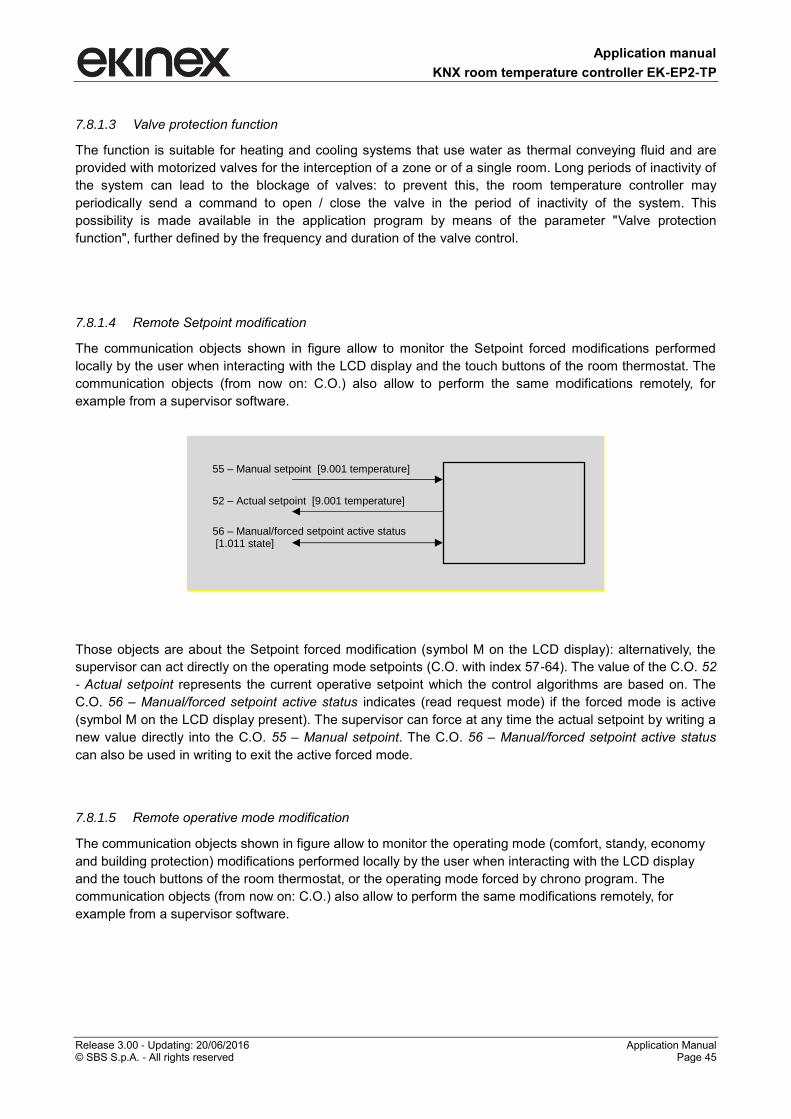
Application manual
KNX room temperature controller EK-EP2-TP
Release 3.00 - Updating: 20/06/2016 Application Manual © SBS S.p.A. - All rights reserved Page 45
7.8.1.3 Valve protection function
The function is suitable for heating and cooling systems that use water as thermal conveying fluid and are
provided with motorized valves for the interception of a zone or of a single room. Long periods of inactivity of
the system can lead to the blockage of valves: to prevent this, the room temperature controller may
periodically send a command to open / close the valve in the period of inactivity of the system. This
possibility is made available in the application program by means of the parameter "Valve protection
function", further defined by the frequency and duration of the valve control.
7.8.1.4 Remote Setpoint modification
The communication objects shown in figure allow to monitor the Setpoint forced modifications performed
locally by the user when interacting with the LCD display and the touch buttons of the room thermostat. The
communication objects (from now on: C.O.) also allow to perform the same modifications remotely, for
example from a supervisor software.
Those objects are about the Setpoint forced modification (symbol M on the LCD display): alternatively, the
supervisor can act directly on the operating mode setpoints (C.O. with index 57-64). The value of the C.O. 52
- Actual setpoint represents the current operative setpoint which the control algorithms are based on. The
C.O. 56 – Manual/forced setpoint active status indicates (read request mode) if the forced mode is active
(symbol M on the LCD display present). The supervisor can force at any time the actual setpoint by writing a
new value directly into the C.O. 55 – Manual setpoint. The C.O. 56 – Manual/forced setpoint active status
can also be used in writing to exit the active forced mode.
7.8.1.5 Remote operative mode modification
The communication objects shown in figure allow to monitor the operating mode (comfort, standy, economy
and building protection) modifications performed locally by the user when interacting with the LCD display
and the touch buttons of the room thermostat, or the operating mode forced by chrono program. The
communication objects (from now on: C.O.) also allow to perform the same modifications remotely, for
example from a supervisor software.
56 – Manual/forced setpoint active status [1.011 state]
55 – Manual setpoint [9.001 temperature]
52 – Actual setpoint [9.001 temperature]
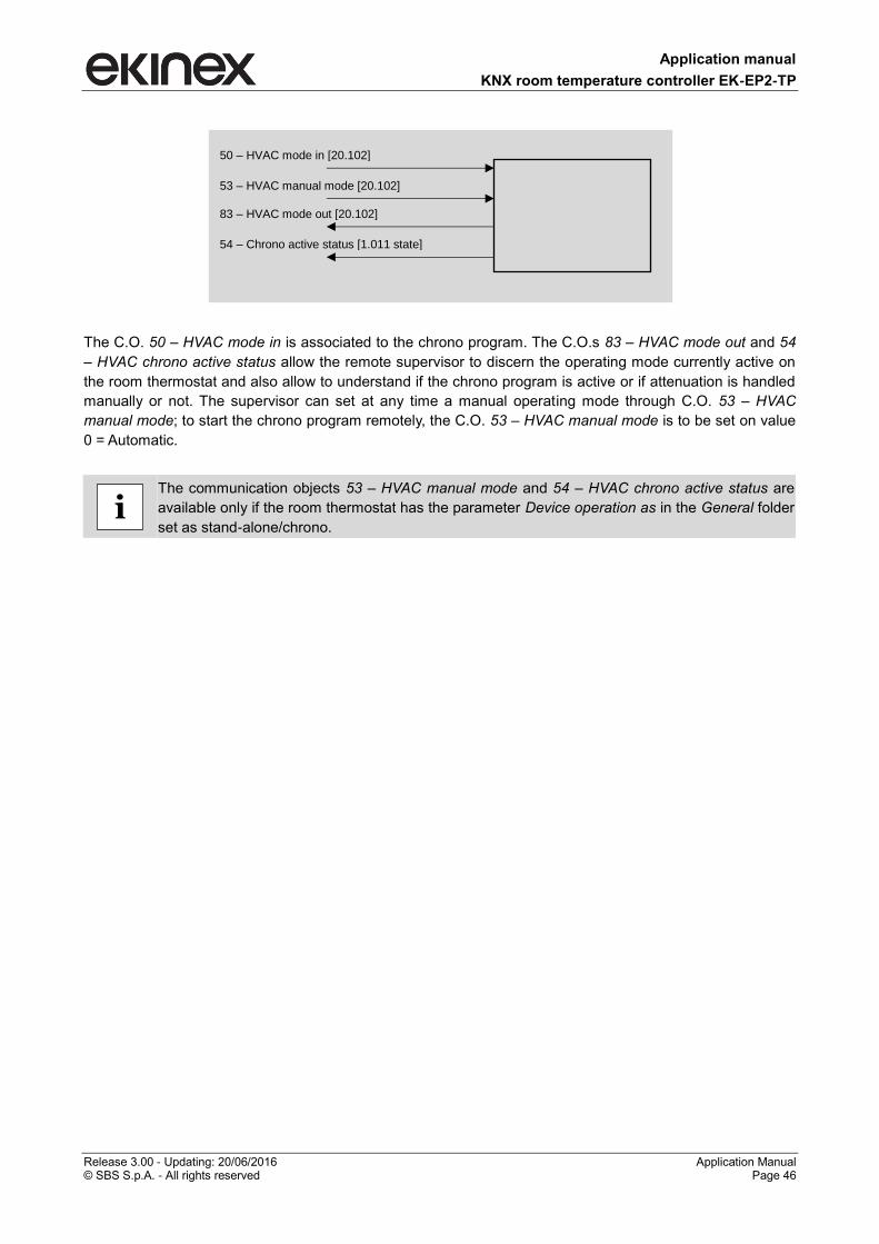
Application manual
KNX room temperature controller EK-EP2-TP
Release 3.00 - Updating: 20/06/2016 Application Manual © SBS S.p.A. - All rights reserved Page 46
The C.O. 50 – HVAC mode in is associated to the chrono program. The C.O.s 83 – HVAC mode out and 54
– HVAC chrono active status allow the remote supervisor to discern the operating mode currently active on
the room thermostat and also allow to understand if the chrono program is active or if attenuation is handled
manually or not. The supervisor can set at any time a manual operating mode through C.O. 53 – HVAC
manual mode; to start the chrono program remotely, the C.O. 53 – HVAC manual mode is to be set on value
0 = Automatic.
The communication objects 53 – HVAC manual mode and 54 – HVAC chrono active status are
available only if the room thermostat has the parameter Device operation as in the General folder
set as stand-alone/chrono.
i
50 – HVAC mode in [20.102]
53 – HVAC manual mode [20.102]
83 – HVAC mode out [20.102]
54 – Chrono active status [1.011 state]
Application manual
KNX room temperature controller EK-EP2-TP
Release 3.00 - Updating: 20/06/2016 Application Manual © SBS S.p.A. - All rights reserved Page 47
7.8.2 Heating
The Heating folder includes the following parameters:
Comfort temp. setpoint [°C]
Standby temperature setpoint [°C]
Economy temp. setpoint [°C]
Building protection temp. setpoint [°C]
Heating type
Control type
Hysteresis
Cyclic sending interval
Min. change of value to send [%]
PWM cycle time
Proportional band [0,1 K]
Integral time [min]
Floor temperature limitation
Temperature limit [°C]
Hysteresis [K]
Auxiliary heating
Communication object
Disabled from bus
Offset from setpoint
Hysteresis
Cyclic sending interval
Ventilation for auxiliary heating
7.8.2.1 Parameters and communication objects
Conditions: Settings Thermostat function = heating or both heating and cooling.
Parameter name Conditions Values
Comfort temp. setpoint [°C] 21
[range 10 … 50]
Standby temperature setpoint [°C] 18
[range 10 … 50]
For a correct operation of the device the standby temperature setpoint has to be <
comfort temperature setpoint.
Economy temp. setpoint [°C] 16
[range 10 … 50]
For a correct operation of the device the economy temperature setpoint has to be <
standby temperature setpoint.
Building protection temp. setpoint [°C] 7
[range 2 … 10]
Heating type
radiators
elettric
fan-coils
floor radiant panels
ceiling radiant panels
It defines the terminal used for the thermal exchange in the room. The choice affects
the parameters of the PWM control algorithm (Proportional band and Integral time) and
the control options.
Application manual
KNX room temperature controller EK-EP2-TP
Release 3.00 - Updating: 20/06/2016 Application Manual © SBS S.p.A. - All rights reserved Page 48
Parameter name Conditions Values
Control type
2 point hysteresis
PWM (pulse width modulation)
continuous
Hysteresis Control type = 2 point hysteresis 0,3 K
[other values in the range 0,2 K … 3 K]
Histeresis position
Cooling type = floor radiant panels or
ceiling radiant panels
Control type = 2 point hysteresis
below
above
The hysteresis position “above” is suited for special applications that require also the
control of the mixing group.
Cyclic sending interval Control type = 2 point hysteresis,
continuous
no sending
[other values in the range 30 s … 120
min]
Min. change of value to send [%] Control type = continuous 10
[range 0 … 100]
PWM cycle time Control type = PWM 15 min
[range 5 … 240 min]
Proportional band [0,1 K] Control type = continuous or PWM *
[range 0 … 255]
The value is in tenths of Kelvin (K) degree.
*) The field contains a preset value that depend on the selected heating type (the value
can be modified):
radiators: 50 ( 5 K)
elettric: 40 (4 K)
fan-coils: 40 (4 K)
floor radiant panels: 50 (5 K)
ceiling radiant panels: 50 (5 K)
The value of the parameter Proportional band represents the max difference between
the setpoint temperature and the measured temperature that causes the max control
output.
Integral time [min] Control type = continuous or PWM *
[other values in the range 0 … 255 min]
*) The field contains a preset value that depend on the selected heating type (the value
can be modified):
radiators: 150 min
elettric: 100 min
fan-coils: 90 min
floor radiant panels: 240 min
ceiling radiant panels: 180 min
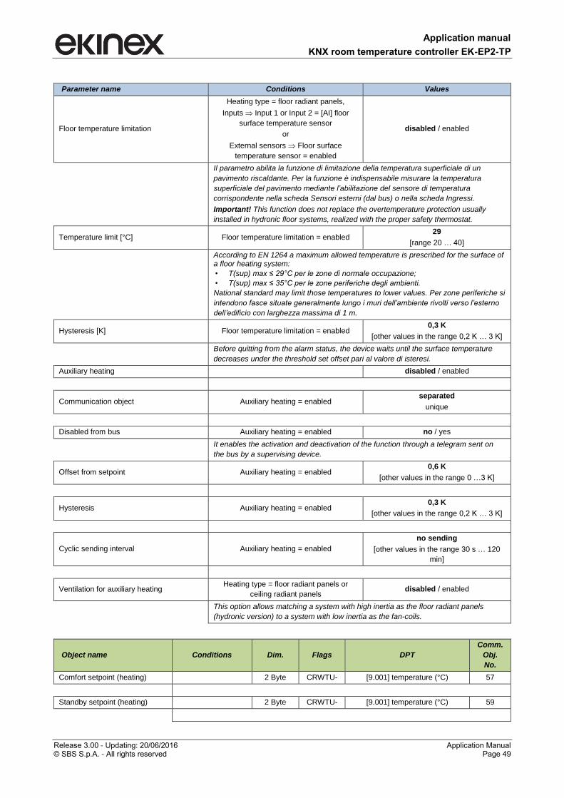
Application manual
KNX room temperature controller EK-EP2-TP
Release 3.00 - Updating: 20/06/2016 Application Manual © SBS S.p.A. - All rights reserved Page 49
Parameter name Conditions Values
Floor temperature limitation
Heating type = floor radiant panels,
Inputs Input 1 or Input 2 = [AI] floor
surface temperature sensor
or
External sensors Floor surface
temperature sensor = enabled
disabled / enabled
Il parametro abilita la funzione di limitazione della temperatura superficiale di un
pavimento riscaldante. Per la funzione è indispensabile misurare la temperatura
superficiale del pavimento mediante l’abilitazione del sensore di temperatura
corrispondente nella scheda Sensori esterni (dal bus) o nella scheda Ingressi.
Important! This function does not replace the overtemperature protection usually
installed in hydronic floor systems, realized with the proper safety thermostat.
Temperature limit [°C] Floor temperature limitation = enabled 29
[range 20 … 40]
According to EN 1264 a maximum allowed temperature is prescribed for the surface of a floor heating system:
• T(sup) max ≤ 29°C per le zone di normale occupazione;
• T(sup) max ≤ 35°C per le zone periferiche degli ambienti.
National standard may limit those temperatures to lower values. Per zone periferiche si
intendono fasce situate generalmente lungo i muri dell’ambiente rivolti verso l’esterno
dell’edificio con larghezza massima di 1 m.
Hysteresis [K] Floor temperature limitation = enabled 0,3 K
[other values in the range 0,2 K … 3 K]
Before quitting from the alarm status, the device waits until the surface temperature
decreases under the threshold set offset pari al valore di isteresi.
Auxiliary heating disabled / enabled
Communication object Auxiliary heating = enabled separated
unique
Disabled from bus Auxiliary heating = enabled no / yes
It enables the activation and deactivation of the function through a telegram sent on
the bus by a supervising device.
Offset from setpoint Auxiliary heating = enabled 0,6 K
[other values in the range 0 …3 K]
Hysteresis Auxiliary heating = enabled 0,3 K
[other values in the range 0,2 K … 3 K]
Cyclic sending interval Auxiliary heating = enabled
no sending
[other values in the range 30 s … 120
min]
Ventilation for auxiliary heating Heating type = floor radiant panels or
ceiling radiant panels disabled / enabled
This option allows matching a system with high inertia as the floor radiant panels
(hydronic version) to a system with low inertia as the fan-coils.
Object name Conditions Dim. Flags DPT
Comm.
Obj.
No.
Comfort setpoint (heating) 2 Byte CRWTU- [9.001] temperature (°C) 57
Standby setpoint (heating) 2 Byte CRWTU- [9.001] temperature (°C) 59
Application manual
KNX room temperature controller EK-EP2-TP
Release 3.00 - Updating: 20/06/2016 Application Manual © SBS S.p.A. - All rights reserved Page 50
Object name Conditions Dim. Flags DPT
Comm.
Obj.
No.
Economy setpoint (heating) 2 Byte CRWTU- [9.001] temperature (°C) 61
Building protection setpoint
(heating) 2 Byte CRWTU- [9.001] temperature (°C) 63
Heating out command
Control type = 2
points hysteresis or
PWM
1 Bit CR-T-- [1.001] switch
65
Control type =
continuous 1 Byte CR-T-- [5.001] percentage (0..100%)
Auxiliary heating output command
Auxiliary heating =
enabled 1 Bit CR-T-- [1.001] switch 67
Auxiliary heating disable
Auxiliary heating =
enabled,
Disabled from bus =
yes
1 Bit C-W--- [1.003] enable 69
About the floor temperature limitation function
The floor heating system (warm water version) provides plastic pipes embedded in the concrete layer or
placed directly under the final coating of the floor (light or "dry" system) filled by heated water. The water
releases heat to the final coating that heats the room by radiation. The standard EN 1264 Floor heating (Part
3: Systems and components - Dimensioning) prescribes a maximum allowed temperature (TSmax) for the
surface of the floor that is physiologically correct defined as:
TSmax ≤ 29°C for zones of normal occupancy;
TSmax ≤ 35°C for peripheral zones of the rooms.
National standards may also limit these temperatures at lower values. Peripheral zones are strips generally
located along the external walls with a maximum width of 1 m.
The floor heating system (electrically powered version) involves the laying under the floor coating of an
electric cable powered by the mains voltage (230 V) or low voltage (for example 12 or 45 V), possibly
already prepared in the form of rolls with constant distance between sections of cable. The powered cable
releases heat to the overlying coating that heats the room by radiation. The regulation is based on
measurement of the temperature of the air mass, but generally requires the monitoring and limiting of the
surface temperature by using a NTC-type sensor which is in contact with the floor surface.
The surface temperature limitation may be realized for several purposes:
physiological compatibility (correct temperature at the height of the legs);
when the system is used as auxiliary stage for heating. In this case, the heat losses to the exterior
of the building are handled by the main heating stage, while the auxiliary stage only works to keep
the floor temperature at a comfortable level (for example in bathrooms of residential buildings,
sports centers , spas and thermal baths, etc.);
protection against damages of the final coating due to an accidental overheating. Note that the
warm water radiant panels are usually already equipped with a safety thermostat (with intervention
on the hydraulic mixing group), while in the case of electrical power this device is not usable and it is
common practice to realize a temperature limitation with a surface temperature sensor connected to
the device.
Application manual
KNX room temperature controller EK-EP2-TP
Release 3.00 - Updating: 20/06/2016 Application Manual © SBS S.p.A. - All rights reserved Page 51
7.8.3 Cooling
The Cooling folder includes the following parameters:
Comfort temp. setpoint [°C]
Standby temperature setpoint [°C]
Economy temp. setpoint [°C]
Building protection temp. setpoint [°C]
Cooling type
Control type
Hysteresis
Cyclic sending interval
Min. change of value to send [%]
PWM cycle time
Proportional band [0,1 K]
Integral time [min]
Anticondensation with probe
Auxiliary cooling
Disabled from bus
Offset from setpoint
Hysteresis
Cyclic sending interval
Ventilation for auxiliary cooling
Conditions: Temperature control Settings Thermostat function = cooling or both heating and cooling.
7.8.3.1 Parameters and communication objects
Parameter name Conditions Values
Comfort temp. setpoint [°C] 23
[range 10 … 50]
Standby temperature setpoint [°C] 26
[range 10 … 50]
For a correct operation of the device the standby temperature setpoint has to be >
comfort temperature setpoint.
Economy temp. setpoint [°C] 28
[range 10 … 50]
For a correct operation of the device the standby temperature setpoint has to be >
economy temperature setpoint.
Building protection temp. setpoint [°C] 36
[range 30 … 50]
Cooling type
fan-coils
floor radiant panels
ceiling radiant panels
If in Settings the parameter Thermostat function = both heating and cooling and
Command communication object = unique, the parameter Cooling type is bound to the
choice done for Heating.
Application manual
KNX room temperature controller EK-EP2-TP
Release 3.00 - Updating: 20/06/2016 Application Manual © SBS S.p.A. - All rights reserved Page 52
Parameter name Conditions Values
Control type Command communication object =
separated
2 point hysteresis
PWM (pulse width modulation)
continuous
If in Settings the parameter Thermostat function = both heating and cooling and
Command communication object = unique, the parameter Control type is bound to the
choice done for Heating.
Hysteresis Control type = 2 point hysteresis 0,3 K
[other values in the range 0,2 K … 3 K]
Hysteresis position
Cooling type = floor radiant panels or
ceiling radiant panels
Control type = 2 point hysteresis
above
below
The hysteresis position “below” is suited for special applications that require also the
control of the mixing group.
Cyclic sending interval Control type = 2 point hysteresis or
continuous
no sending
[other values in the range 30 s … 120
min]
Min. change of value to send [%] Control type = continuous 10
[range 0 … 100]
PWM cycle time Control type = PWM (pulsa width
modulation)
15 min
[range 5 … 240 min]
Proportional band [0,1 K] Control type = continuous or PWM *
[range 0 … 255]
The value is in tenths of Kelvin (K) degree.
*) The field contains a preset value that depend on the selected cooling type (the value
can be modified):
fan-coils: 40 (4 K)
floor radiant panels: 50 (5 K)
ceiling radiant panels: 50 (5 K)
The value of the parameter Proportional band represents the max difference between
the setpoint temperature and the measured temperature that causes the max control
output.
Integral time [min] Control type = continuous or PWM *
[range 0 … 255 min]
*) The field contains a preset value that depend on the selected cooling type (the value can be modified):
fan-coils: 90 min
floor radiant panels: 240 min
ceiling radiant panels: 180 min
Anticondensation with probe
Cooling type = floor radiant panels or
ceiling radiant panels,
Inputs Input 1 or Input 2 = [DI]
anticondensation sensor
or
External sensors (from bus)
Anticondensation = enabled
disabled / enabled
Auxiliary cooling disabled / enabled
Disabled from bus Auxiliary cooling = enabled no / yes
This parameter enables the activation and deactivation of the function through a
telegram from a bus device with supervising function.
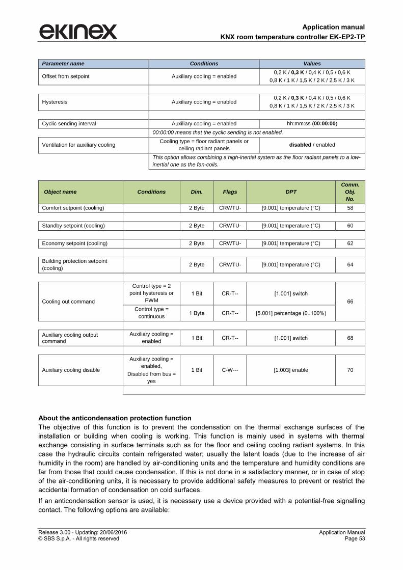
Application manual
KNX room temperature controller EK-EP2-TP
Release 3.00 - Updating: 20/06/2016 Application Manual © SBS S.p.A. - All rights reserved Page 53
Parameter name Conditions Values
Offset from setpoint Auxiliary cooling = enabled 0,2 K / 0,3 K / 0,4 K / 0,5 / 0,6 K
0,8 K / 1 K / 1,5 K / 2 K / 2,5 K / 3 K
Hysteresis Auxiliary cooling = enabled 0,2 K / 0,3 K / 0,4 K / 0,5 / 0,6 K
0,8 K / 1 K / 1,5 K / 2 K / 2,5 K / 3 K
Cyclic sending interval Auxiliary cooling = enabled hh:mm:ss (00:00:00)
00:00:00 means that the cyclic sending is not enabled.
Ventilation for auxiliary cooling Cooling type = floor radiant panels or
ceiling radiant panels disabled / enabled
This option allows combining a high-inertial system as the floor radiant panels to a low-
inertial one as the fan-coils.
Object name Conditions Dim. Flags DPT
Comm.
Obj.
No.
Comfort setpoint (cooling) 2 Byte CRWTU- [9.001] temperature (°C) 58
Standby setpoint (cooling) 2 Byte CRWTU- [9.001] temperature (°C) 60
Economy setpoint (cooling) 2 Byte CRWTU- [9.001] temperature (°C) 62
Building protection setpoint
(cooling) 2 Byte CRWTU- [9.001] temperature (°C) 64
Cooling out command
Control type = 2
point hysteresis or
PWM
1 Bit CR-T-- [1.001] switch
66
Control type =
continuous 1 Byte CR-T-- [5.001] percentage (0..100%)
Auxiliary cooling output command
Auxiliary cooling =
enabled 1 Bit CR-T-- [1.001] switch 68
Auxiliary cooling disable
Auxiliary cooling =
enabled,
Disabled from bus =
yes
1 Bit C-W--- [1.003] enable 70
About the anticondensation protection function
The objective of this function is to prevent the condensation on the thermal exchange surfaces of the
installation or building when cooling is working. This function is mainly used in systems with thermal
exchange consisting in surface terminals such as for the floor and ceiling cooling radiant systems. In this
case the hydraulic circuits contain refrigerated water; usually the latent loads (due to the increase of air
humidity in the room) are handled by air-conditioning units and the temperature and humidity conditions are
far from those that could cause condensation. If this is not done in a satisfactory manner, or in case of stop
of the air-conditioning units, it is necessary to provide additional safety measures to prevent or restrict the
accidental formation of condensation on cold surfaces.
If an anticondensation sensor is used, it is necessary use a device provided with a potential-free signalling
contact. The following options are available:
Application manual
KNX room temperature controller EK-EP2-TP
Release 3.00 - Updating: 20/06/2016 Application Manual © SBS S.p.A. - All rights reserved Page 54
the connection of the signalling contact to an input of the room temperature controller configured as
digital (Inputs Input 1 or Input 2 = [DI] anticondensation sensor). The signal coming from the
sensor is received and processed directly by the room temperature controller (case 1a of the table);
the connection of the signalling contact to an input channel of another KNX device, e.g. a pushbutton
interface or a binary input (External sensors (from bus) Anticondensation sensor = enabled). In
this case the signal of the sensor is transmitted to the room temperature controller through the status
of a communication object (case 1b of the table).
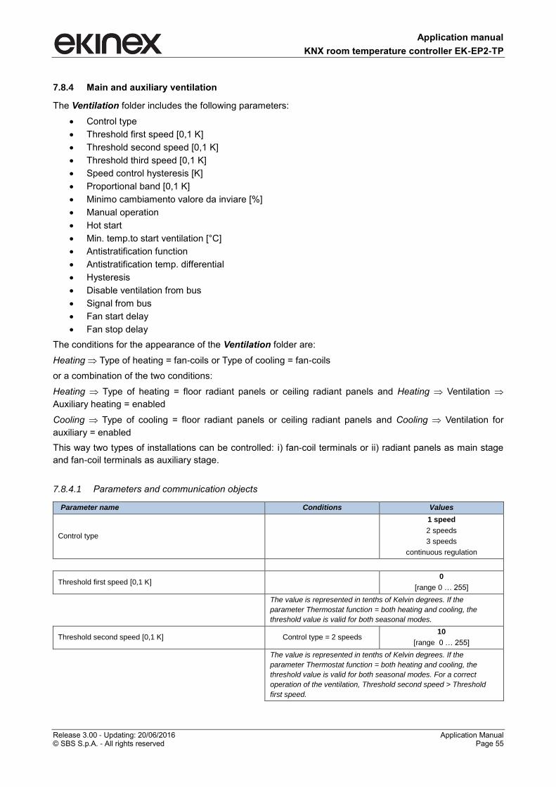
Application manual
KNX room temperature controller EK-EP2-TP
Release 3.00 - Updating: 20/06/2016 Application Manual © SBS S.p.A. - All rights reserved Page 55
7.8.4 Main and auxiliary ventilation
The Ventilation folder includes the following parameters:
Control type
Threshold first speed [0,1 K]
Threshold second speed [0,1 K]
Threshold third speed [0,1 K]
Speed control hysteresis [K]
Proportional band [0,1 K]
Minimo cambiamento valore da inviare [%]
Manual operation
Hot start
Min. temp.to start ventilation [°C]
Antistratification function
Antistratification temp. differential
Hysteresis
Disable ventilation from bus
Signal from bus
Fan start delay
Fan stop delay
The conditions for the appearance of the Ventilation folder are:
Heating Type of heating = fan-coils or Type of cooling = fan-coils
or a combination of the two conditions:
Heating Type of heating = floor radiant panels or ceiling radiant panels and Heating Ventilation
Auxiliary heating = enabled
Cooling Type of cooling = floor radiant panels or ceiling radiant panels and Cooling Ventilation for
auxiliary = enabled
This way two types of installations can be controlled: i) fan-coil terminals or ii) radiant panels as main stage
and fan-coil terminals as auxiliary stage.
7.8.4.1 Parameters and communication objects
Parameter name Conditions Values
Control type
1 speed
2 speeds
3 speeds
continuous regulation
Threshold first speed [0,1 K] 0
[range 0 … 255]
The value is represented in tenths of Kelvin degrees. If the
parameter Thermostat function = both heating and cooling, the
threshold value is valid for both seasonal modes.
Threshold second speed [0,1 K] Control type = 2 speeds 10
[range 0 … 255]
The value is represented in tenths of Kelvin degrees. If the
parameter Thermostat function = both heating and cooling, the
threshold value is valid for both seasonal modes. For a correct
operation of the ventilation, Threshold second speed > Threshold
first speed.
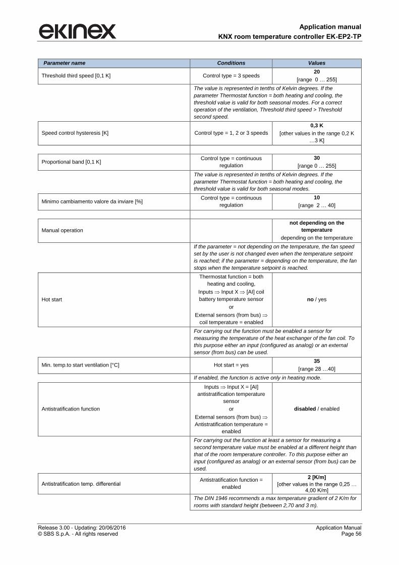
Application manual
KNX room temperature controller EK-EP2-TP
Release 3.00 - Updating: 20/06/2016 Application Manual © SBS S.p.A. - All rights reserved Page 56
Parameter name Conditions Values
Threshold third speed [0,1 K] Control type = 3 speeds 20
[range 0 … 255]
The value is represented in tenths of Kelvin degrees. If the
parameter Thermostat function = both heating and cooling, the
threshold value is valid for both seasonal modes. For a correct
operation of the ventilation, Threshold third speed > Threshold
second speed.
Speed control hysteresis [K] Control type = 1, 2 or 3 speeds
0,3 K
[other values in the range 0,2 K
…3 K]
Proportional band [0,1 K] Control type = continuous
regulation
30
[range 0 … 255]
The value is represented in tenths of Kelvin degrees. If the
parameter Thermostat function = both heating and cooling, the
threshold value is valid for both seasonal modes.
Minimo cambiamento valore da inviare [%] Control type = continuous
regulation
10
[range 2 … 40]
Manual operation
not depending on the
temperature
depending on the temperature
If the parameter = not depending on the temperature, the fan speed
set by the user is not changed even when the temperature setpoint
is reached; if the parameter = depending on the temperature, the fan
stops when the temperature setpoint is reached.
Hot start
Thermostat function = both
heating and cooling,
Inputs Input X [AI] coil
battery temperature sensor
or
External sensors (from bus)
coil temperature = enabled
no / yes
For carrying out the function must be enabled a sensor for
measuring the temperature of the heat exchanger of the fan coil. To
this purpose either an input (configured as analog) or an external
sensor (from bus) can be used.
Min. temp.to start ventilation [°C] Hot start = yes 35
[range 28 …40]
If enabled, the function is active only in heating mode.
Antistratification function
Inputs Input X = [AI]
antistratification temperature
sensor
or
External sensors (from bus)
Antistratification temperature =
enabled
disabled / enabled
For carrying out the function at least a sensor for measuring a
second temperature value must be enabled at a different height than
that of the room temperature controller. To this purpose either an
input (configured as analog) or an external sensor (from bus) can be
used.
Antistratification temp. differential Antistratification function =
enabled
2 [K/m]
[other values in the range 0,25 … 4,00 K/m]
The DIN 1946 recommends a max temperature gradient of 2 K/m for
rooms with standard height (between 2,70 and 3 m).
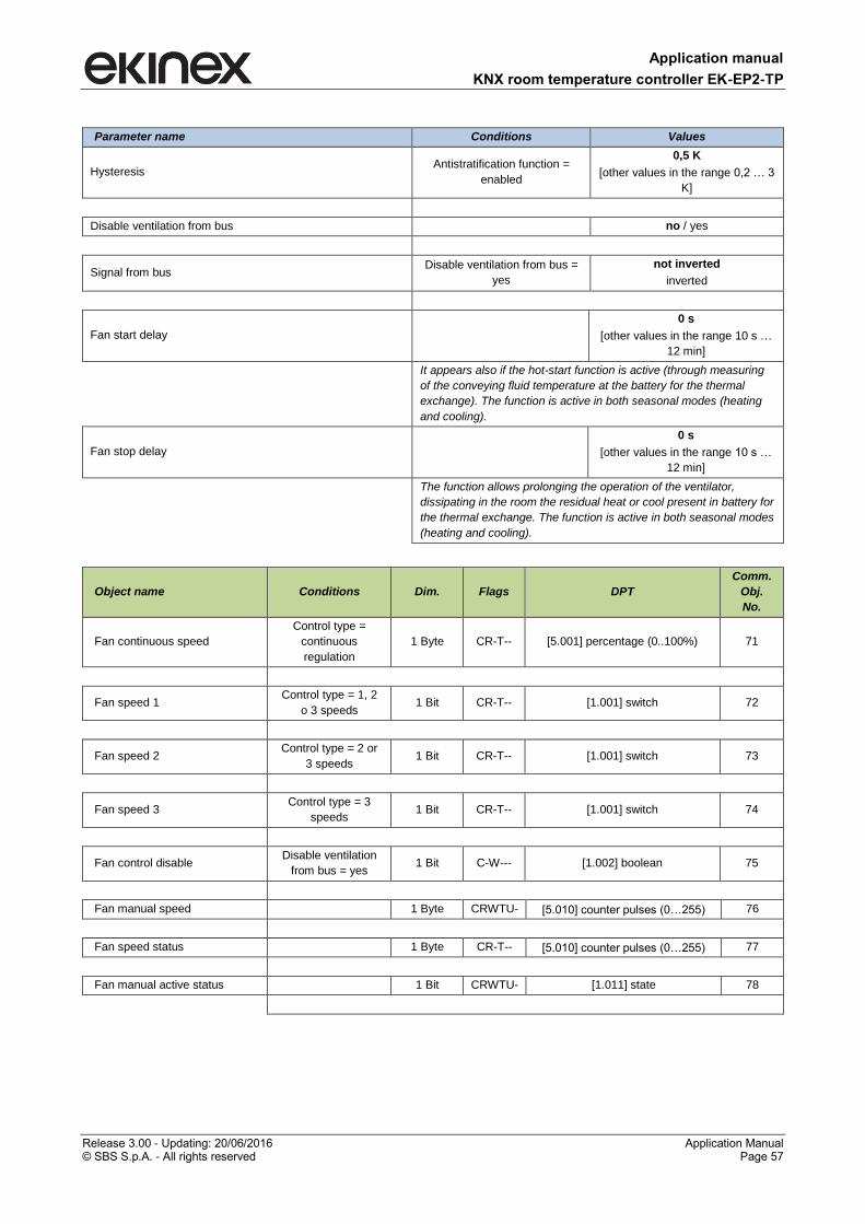
Application manual
KNX room temperature controller EK-EP2-TP
Release 3.00 - Updating: 20/06/2016 Application Manual © SBS S.p.A. - All rights reserved Page 57
Parameter name Conditions Values
Hysteresis Antistratification function =
enabled
0,5 K
[other values in the range 0,2 … 3
K]
Disable ventilation from bus no / yes
Signal from bus Disable ventilation from bus =
yes
not inverted
inverted
Fan start delay
0 s
[other values in the range 10 s …
12 min]
It appears also if the hot-start function is active (through measuring
of the conveying fluid temperature at the battery for the thermal
exchange). The function is active in both seasonal modes (heating
and cooling).
Fan stop delay
0 s
[other values in the range 10 s …
12 min]
The function allows prolonging the operation of the ventilator,
dissipating in the room the residual heat or cool present in battery for
the thermal exchange. The function is active in both seasonal modes
(heating and cooling).
Object name Conditions Dim. Flags DPT
Comm.
Obj.
No.
Fan continuous speed
Control type =
continuous
regulation
1 Byte CR-T-- [5.001] percentage (0..100%) 71
Fan speed 1 Control type = 1, 2
o 3 speeds 1 Bit CR-T-- [1.001] switch 72
Fan speed 2 Control type = 2 or
3 speeds 1 Bit CR-T-- [1.001] switch 73
Fan speed 3 Control type = 3
speeds 1 Bit CR-T-- [1.001] switch 74
Fan control disable Disable ventilation
from bus = yes 1 Bit C-W--- [1.002] boolean 75
Fan manual speed 1 Byte CRWTU- [5.010] counter pulses (0…255) 76
Fan speed status 1 Byte CR-T-- [5.010] counter pulses (0…255) 77
Fan manual active status 1 Bit CRWTU- [1.011] state 78
Application manual
KNX room temperature controller EK-EP2-TP
Release 3.00 - Updating: 20/06/2016 Application Manual © SBS S.p.A. - All rights reserved Page 58
7.8.4.2 Delayed fan start (“hot-start”) function
This function is used in case the fan forces in the room air passing through a heat exchange coil (as in the
case of the terminals to the fan-coil). In the heating mode of operation, to avoid possible discomfort caused
by the dispatch of cold air in the room, the room temperature controller does not start the fan until the fluid
has not reached a sufficiently high temperature. This situation normally occurs at the first start or after long
periods of inactivity. The function can be carried out by:
1. a temperature control (through a temperature sensor on the coil exchange battery);
2. a delayed start (function approximated);
In the first case the temperature of the heat conveying fluid is acquired at the exchange battery. The function
then has an effective temperature control, but for the execution is necessary that:
the heat exchange coil is equipped with a sensor of minimum water temperature that acquires the
temperature of the heat conveying fluid;
the sensor is connected to an input of the room temperature controller (configured as analog) or to
another KNX device with an analog input.
In the second case just sets a time delay starting from the flow request; there is no temperature control. The
effectiveness of the function depends on a field measurement of the time actually required to have
sufficiently warm air from the terminal.
7.8.4.3 Antistratification function
This function is used in the case of heating systems with thermal exchange of convective type for rooms with
height and volume much higher than usual (atriums, fitness facility, commercial buildings, etc.). Because of
the natural convection - with warm air rising to the highest altitudes of the room - the phenomenon of air
stratification occurs, with energy waste and discomfort for the occupants at the same time. The function
opposes to the air stratification, forcing the warm air downwards.
The antistratification function requires:
rooms of great height;
availability of ventilation devices able to force the air movement downwards (opposed to the natural
convective movement of warm air);
measuring of the temperature at two heights through the installation of a second temperature sensor
at an adequate height in order to measure the actual air stratification (the main room temperature
controller is supposed to be installed at 1.5 m).
For rooms with ordinary height (2,70÷3,00 m) the DIN 1946 standard recommends not to exceed 2 K/m in
order to have an adequate comfort; this gradient may be bigger in higher rooms.
7.8.4.4 The 2-stage configuration with fan-coils as auxiliary stage
The fan-coil units may be used both as a main stage and secondary stage. As main stage they can be
combined only to radiators as auxiliary stage. If, however, the main stage is done with (floor or ceiling)
radiant panels, the fan-coils can be used as auxiliary stage. In the latter case they work in automatic mode
with a configurable offset with respect to the temperature setpoint for the main stage, and then carry out their
compensation function while the main stage is brought in temperature with bigger inertia.
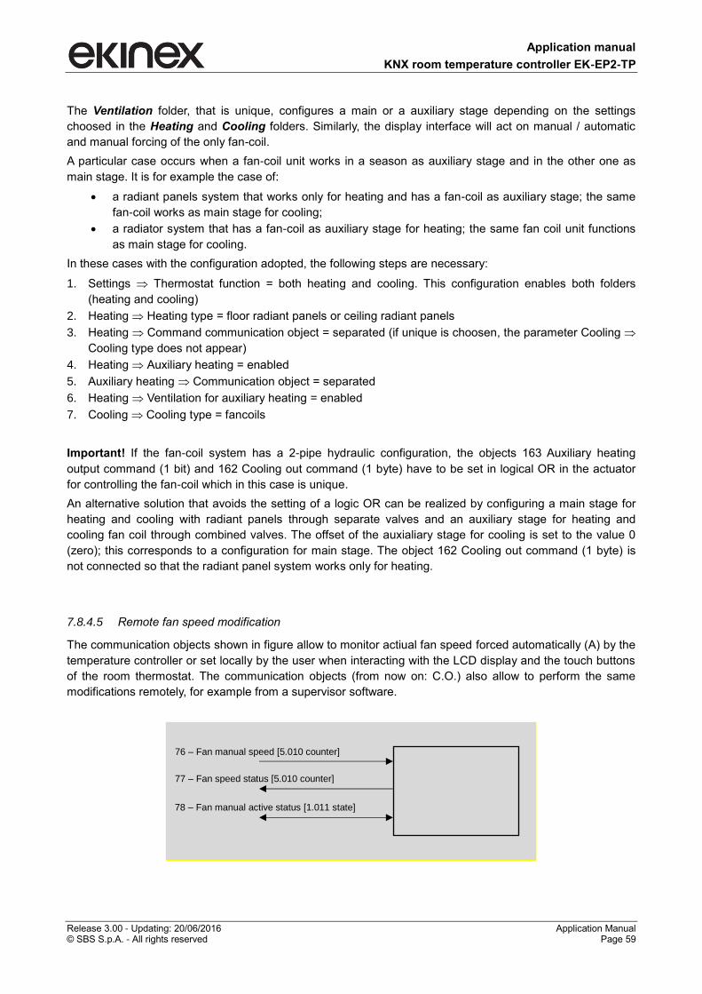
Application manual
KNX room temperature controller EK-EP2-TP
Release 3.00 - Updating: 20/06/2016 Application Manual © SBS S.p.A. - All rights reserved Page 59
The Ventilation folder, that is unique, configures a main or a auxiliary stage depending on the settings
choosed in the Heating and Cooling folders. Similarly, the display interface will act on manual / automatic
and manual forcing of the only fan-coil.
A particular case occurs when a fan-coil unit works in a season as auxiliary stage and in the other one as
main stage. It is for example the case of:
a radiant panels system that works only for heating and has a fan-coil as auxiliary stage; the same
fan-coil works as main stage for cooling;
a radiator system that has a fan-coil as auxiliary stage for heating; the same fan coil unit functions
as main stage for cooling.
In these cases with the configuration adopted, the following steps are necessary:
1. Settings Thermostat function = both heating and cooling. This configuration enables both folders
(heating and cooling)
2. Heating Heating type = floor radiant panels or ceiling radiant panels
3. Heating Command communication object = separated (if unique is choosen, the parameter Cooling
Cooling type does not appear)
4. Heating Auxiliary heating = enabled
5. Auxiliary heating Communication object = separated
6. Heating Ventilation for auxiliary heating = enabled
7. Cooling Cooling type = fancoils
Important! If the fan-coil system has a 2-pipe hydraulic configuration, the objects 163 Auxiliary heating
output command (1 bit) and 162 Cooling out command (1 byte) have to be set in logical OR in the actuator
for controlling the fan-coil which in this case is unique.
An alternative solution that avoids the setting of a logic OR can be realized by configuring a main stage for
heating and cooling with radiant panels through separate valves and an auxiliary stage for heating and
cooling fan coil through combined valves. The offset of the auxialiary stage for cooling is set to the value 0
(zero); this corresponds to a configuration for main stage. The object 162 Cooling out command (1 byte) is
not connected so that the radiant panel system works only for heating.
7.8.4.5 Remote fan speed modification
The communication objects shown in figure allow to monitor actiual fan speed forced automatically (A) by the
temperature controller or set locally by the user when interacting with the LCD display and the touch buttons
of the room thermostat. The communication objects (from now on: C.O.) also allow to perform the same
modifications remotely, for example from a supervisor software.
77 – Fan speed status [5.010 counter]
78 – Fan manual active status [1.011 state]
76 – Fan manual speed [5.010 counter]
Application manual
KNX room temperature controller EK-EP2-TP
Release 3.00 - Updating: 20/06/2016 Application Manual © SBS S.p.A. - All rights reserved Page 60
The C.O. 77 – Fan manual status allows to evaluate the actual fan speed; the C.O. 78 – Fan manual active
status contains the information about automatic (=0, not active) or manual (=1, active) operating mode. By
modifying the C.O. 76 – Fan manual speed, the fan automatically switches to the setpoint speed; to return to
automatic mode (A), the supervisor must exit from manual mode by modifying the C.O. 78 – Fan manual
active status (=0, not active).
Accepted values for C.O.s 76 and 77 depend on the number of speeds set in ETS.
If Control Type parameter in Ventilation folder is = 1, 2 or 3 speeds, C.O.s with DPT [5.010 counter] accept
the following values:
= 0: OFF
= 1: speed 1
= 2: speed 2 (if Control Type > 1 speed)
= 3: speed 3 (if Control Type > 2 speed)
If Control Type parameter in Ventilation folder is = continuous regulation, the values of the C.O.s with DPT
[5.010 counter] match the following percentage of the maximum speed:
= 0: OFF
= 1: 20%
= 2: 40%
= 3: 60%
= 4: 80%
= 5: 100%
Application manual
KNX room temperature controller EK-EP2-TP
Release 3.00 - Updating: 20/06/2016 Application Manual © SBS S.p.A. - All rights reserved Page 61
7.8.5 Scenes
The folder allows the scenes configuration (up to 8), assigning to each one an identification number and the
operating mode to be activated when recalled (e.g. with an ekinex pushbutton or another KNX device with
this function). If Learning mode = enabled, receiving a telegram of scene storage determines the association
of the scene to the operating mode currently set on the device.
Important! Be careful setting the Download overwrite parameter. The download of the application program,
particularly after the first commissioning of the system, may cause the loss of the already stored scenes.
The Scenes folder includes the following parameters:
Download overwrite
Scene X
Scene number
HVAC mode
Activation delay
Learning mode
Condition: Temperature control Settings Scenes = enabled.
7.8.5.1 Parameters and communication objects
Parameter name Conditions Values
Download overwrite disabled / enabled
If Overwrite download = disabled: at the download of the application on the device, the operating modes previously stored are not overwritten.
If Overwrite download = enabled: at the download of the application
on the device, the operating modes previously stored are
reprogrammed with the values selected from the HVAC mode
parameter.
Scene X disabled / enabled
This parameter enables the scene X (X = 1, 2, … 8).
Scene number Scene X = enabled 1
[range 1 … 64]
HVAC mode Scene X = enabled auto / comfort/ standby /
economy / building protection
This parameter defines the operating mode of the scene X.
Activation delay Scene X = enabled hh:mm:ss (00:00:00)
Receiving a telegram that recalls a scene, once elapsed the time
interval set in the Activation delay parameter, the programmed
operating mode is activated.
Learning mode Scene X = enabled disabled / enabled
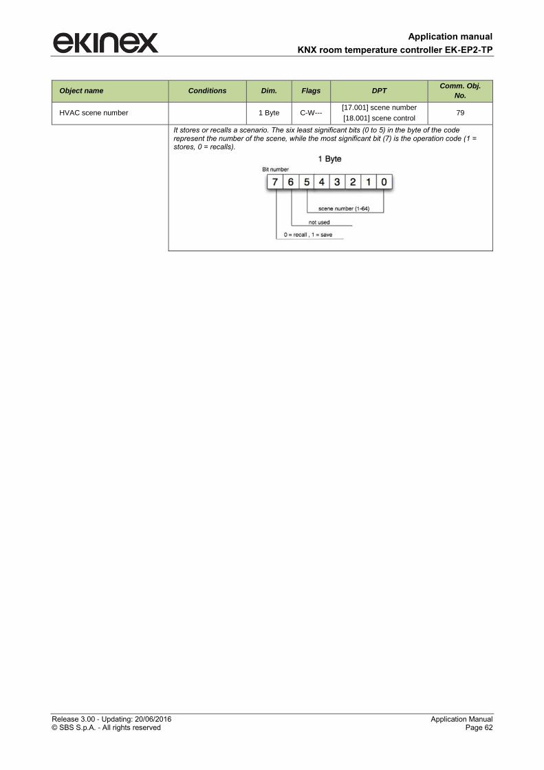
Application manual
KNX room temperature controller EK-EP2-TP
Release 3.00 - Updating: 20/06/2016 Application Manual © SBS S.p.A. - All rights reserved Page 62
Object name Conditions Dim. Flags DPT Comm. Obj.
No.
HVAC scene number 1 Byte C-W--- [17.001] scene number
[18.001] scene control 79
It stores or recalls a scenario. The six least significant bits (0 to 5) in the byte of the code represent the number of the scene, while the most significant bit (7) is the operation code (1 = stores, 0 = recalls).
Application manual
KNX room temperature controller EK-EP2-TP
Release 3.00 - Updating: 20/06/2016 Application Manual © SBS S.p.A. - All rights reserved Page 63
7.9 Energy saving
In order to realise energy-saving functions, window contacts (to detect the opening of windows or doors),
presence and movement sensors and card holders can be used.
The Energy saving folder includes the following secondary folders:
Window contacts
Presence sensors
Card holder
7.9.1 Window contacts
The Window contacts secondary folder appears if at least a sensor dedicated to this function is enabled i.e.
if at least one of the two conditions is verified:
1) Inputs Input 1 and/or Input 2 = [DI] windows contact sensor
2) External sensors (from bus) Windows contact sensor 1 or 2 (from bus) = enabled
For the function can be acquired up to four signals which are combined as a logic OR.
The Window contacts folder includes the following parameters:
Window contacts function
Wait time to building protection mode
7.9.1.1 Parameters and communication objects
Parameter name Conditions Values
Window contacts function disabled / enabled
This parameter enables the window contact function.
Wait time to building protection mode Window contacts function = enabled 00:01:00 hh:mm:ss
[range 00:00:00 … 18:12:15]
Time interval before the automatic switching of the device to the Building protection
operating mode.
Object name Conditions Dim. Flags DPT Comm.
Obj. No.
Window contact sensor (from
input 1)
Window contacts function =
enabled,
Input 1 = [DI] windows contact
sensor
1 Bit CR-T- [1.019]
window/door 26
Window contact sensor (from
input 2)
Window contacts function =
enabled,
Input 2 = [DI] windows contact
sensor
1 Bit CR-T- [1.019]
window/door 27
Windows contact sensor 1
(from bus)
Window contacts function =
enabled,
Window contact 1 = enabled
1 Bit C-W-- [1.019]
window/door 43
Windows contact sensor 2
(from bus)
Window contacts function =
enabled,
Window contact 2 = enabled
1 Bit C-W-- [1.019]
window/door 44
Application manual
KNX room temperature controller EK-EP2-TP
Release 3.00 - Updating: 20/06/2016 Application Manual © SBS S.p.A. - All rights reserved Page 64
7.9.2 Presence sensors
The Presence sensors folder includes the following parameters:
Presence sensor function
Presence sensors use
Thermostat modes
Absence time to switch HVAC mode
For this function only use external sensors (from bus) can be used, such as the ekinex EK-SM2-TP
movement sensor or the ekinex EK-DX2-TP (X = B, C, D, E) presence sensor. The following condition has to
be true:
External sensors (from bus) Presence sensor 1 (from bus) or Presence sensor 2 (from bus) = enabled
7.9.2.1 Parameters and communication objects
Parameter name Conditions Values
Presence sensor function disabled / enabled
Parameter that enables the presence sensor function.
Presence sensors use Presence sensor function = enabled
comfort extension
comfort limitation
comfort extension and comfort limitation
Thermostat modes
Presence sensor function = enabled,
Presence sensors use = comfort
extension and comfort limitation or =
comfort limitation
comfort-standby
comfort-economy
Absence time to switch HVAC mode Presence sensor function = enabled 00:01:00 hh:mm:ss
[range 00:00:00 … 18:12:15]
Time interval before the automatic switching of the operating mode set in the
Thermostat modes parameter.
Object name Conditions Dim. Flags DPT Comm.
Obj. No.
Presence sensor 1 (from bus) Presence sensor function=
enabled 1 Bit C-W---
[1.018]
occupancy 32
Presence sensor 2 (from bus) Presence sensor function =
enabled 1 Bit C-W---
[1.018]
occupancy 33
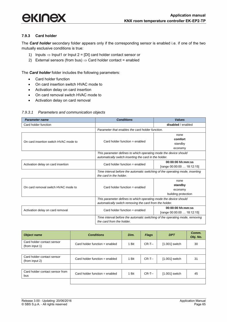
Application manual
KNX room temperature controller EK-EP2-TP
Release 3.00 - Updating: 20/06/2016 Application Manual © SBS S.p.A. - All rights reserved Page 65
7.9.3 Card holder
The Card holder secondary folder appears only if the corresponding sensor is enabled i.e. if one of the two
mutually esclusive conditions is true:
1) Inputs Input1 or Input 2 = [DI] card holder contact sensor or
2) External sensors (from bus) Card holder contact = enabled
The Card holder folder includes the following parameters:
Card holder function
On card insertion switch HVAC mode to
Activation delay on card insertion
On card removal switch HVAC mode to
Activation delay on card removal
7.9.3.1 Parameters and communication objects
Parameter name Conditions Values
Card holder function disabled / enabled
Parameter that enables the card holder function.
On card insertion switch HVAC mode to Card holder function = enabled
none
comfort
standby
economy
This parameter defines to which operating mode the device should
automatically switch inserting the card in the holder.
Activation delay on card insertion Card holder function = enabled 00:00:00 hh:mm:ss
[range 00:00:00 … 18:12:15]
Time interval before the automatic switching of the operating mode, inserting
the card in the holder.
On card removal switch HVAC mode to Card holder function = enabled
none
standby
economy
building protection
This parameter defines to which operating mode the device should
automatically switch removing the card from the holder.
Activation delay on card removal Card holder function = enabled 00:00:00 hh:mm:ss
[range 00:00:00 … 18:12:15]
Time interval before the automatic switching of the operating mode, removing
the card from the holder.
Object name Conditions Dim. Flags DPT Comm.
Obj. No.
Card holder contact sensor
(from input 1) Card holder function = enabled 1 Bit CR-T-- [1.001] switch 30
Card holder contact sensor
(from input 2) Card holder function = enabled 1 Bit CR-T-- [1.001] switch 31
Card holder contact sensor from
bus Card holder function = enabled 1 Bit CR-T-- [1.001] switch 45
Application manual
KNX room temperature controller EK-EP2-TP
Release 3.00 - Updating: 20/06/2016 Application Manual © SBS S.p.A. - All rights reserved Page 66
About the card holder function
The information of card insertion (removal) in (from) a card holder allows you to directly control the
temperature by means of the room thermostat, while sending the object value on the bus allows you to
control other room functions with KNX (lighting, electrical loads, feedback status for the hotel reception, etc.)
depending on the configuration done with ETS. The value of the setpoint temperature and the switching have
to be defined with the hotel responsible in accordance with the target of energy saving and level of service to
be offered to the guests.
Conventional (not KNX) card holder
With a conventional card holder the status (card present or absent) of a signal contact is detected through an
input of the device configured as [DI] card holder contact sensor. This way you can detect only the insertion
and extraction of the card, but it cannot be detected e.g. the access of users with different profiles (guests,
service staff, maintenance workforce).
KNX card holder
With a KNX card holder you can differentiate the switching to be carried out; this is not resolved by the
parameters of the room temperature controller, but through the definition of scenes that are received by the
device. Depending on the available device, advanced functions are possible (e.g. different user profiles).
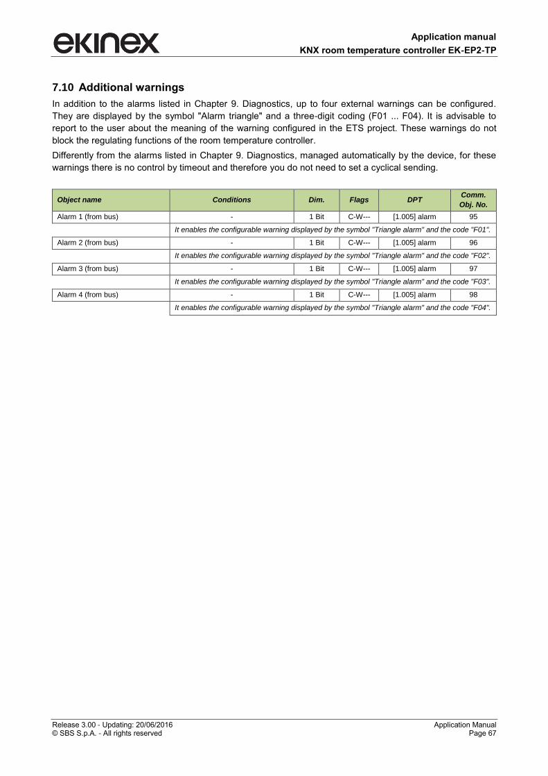
Application manual
KNX room temperature controller EK-EP2-TP
Release 3.00 - Updating: 20/06/2016 Application Manual © SBS S.p.A. - All rights reserved Page 67
7.10 Additional warnings
In addition to the alarms listed in Chapter 9. Diagnostics, up to four external warnings can be configured.
They are displayed by the symbol "Alarm triangle" and a three-digit coding (F01 ... F04). It is advisable to
report to the user about the meaning of the warning configured in the ETS project. These warnings do not
block the regulating functions of the room temperature controller.
Differently from the alarms listed in Chapter 9. Diagnostics, managed automatically by the device, for these
warnings there is no control by timeout and therefore you do not need to set a cyclical sending.
Object name Conditions Dim. Flags DPT Comm.
Obj. No.
Alarm 1 (from bus) - 1 Bit C-W--- [1.005] alarm 95
It enables the configurable warning displayed by the symbol "Triangle alarm" and the code "F01".
Alarm 2 (from bus) - 1 Bit C-W--- [1.005] alarm 96
It enables the configurable warning displayed by the symbol "Triangle alarm" and the code "F02".
Alarm 3 (from bus) - 1 Bit C-W--- [1.005] alarm 97
It enables the configurable warning displayed by the symbol "Triangle alarm" and the code "F03".
Alarm 4 (from bus) - 1 Bit C-W--- [1.005] alarm 98
It enables the configurable warning displayed by the symbol "Triangle alarm" and the code "F04".

Application manual
KNX room temperature controller EK-EP2-TP
Release 3.00 - Updating: 20/06/2016 Application Manual © SBS S.p.A. - All rights reserved Page 68
7.11 Logic functions The KNX room thermostat EK-EP2-TP allows to use some useful logic functions (AND, OR, NOT and
exclusive OR) in order to implement complex functions in the building automation system.
You can configure:
8 channels of logical functions
4 inputs for each channel
Each object value, if desired, can be individually inverted by inserting a NOT logic operator.
For each channel, a parameter Delay after bus voltage recovery is available: this parameter represents the
time interval between the bus voltage recovery and the first reading of the input communication objects for
evaluating the logic functions.
In case of uncorrect connection of the input communication object or electrical trouble on bus
resulting in a failed input reading request, the logic output of the corresponding channel can be
calculated by setting the input values to default.
The communicaton function representing the logic function output is sent on the bus on event of change;
alternatively, a cyclic sending can be set.
7.11.1 Parameters and communication objects
The following condition has to be true: General Logic functions = enabled.
Parameter name Conditions Values
Logic function disabled / enabled
Logic operation Logic function = enabled OR / AND / XOR
XOR (eXclusive OR)
Delay after bus voltage recovery 00:00:04.000 hh:mm:ss.fff
[range 00:00:00.000 … 00:10:55.350]
Time interval between the bus voltage recovery and the first reading of the input
communication objects for evaluating the logic functions
Output cyclic transmission delay no sending
[other value in range 30 s … 120 min]
No sending means that the output state of the logic function is updated on the bus
only on change. Different values imply cyclic sending on the bus of the output state.
Logic object x disabled / enabled
Negated Logic object x = enabled no / yes
Negando lo stato logico dell’ingresso corrispondente, è possibile realizzare logiche
combinatorie articolate. Esempio: Output=(NOT(Oggetto logico 1) OR Oggetto
logico 2).
Read at startup Logic object x = enabled no / yes
Default value Logic object x = enabled none / off / on
i
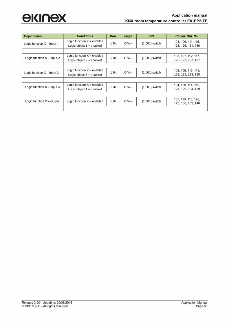
Application manual
KNX room temperature controller EK-EP2-TP
Release 3.00 - Updating: 20/06/2016 Application Manual © SBS S.p.A. - All rights reserved Page 69
Object name Conditions Dim. Flags DPT Comm. Obj. No.
Logic function X – Input 1 Logic function X = enabled
Logic object 1 = enabled 1 Bit C-W-- [1.001] switch
101, 106, 111, 116,
121, 126, 131, 136
Logic function X – Input 2 Logic function X = enabled
Logic object 2 = enabled 1 Bit C-W-- [1.001] switch
102, 107, 112, 117,
122, 127, 132, 137
Logic function X – Input 3 Logic function X = enabled
Logic object 3 = enabled 1 Bit C-W-- [1.001] switch
103, 108, 113, 118,
123, 128, 133, 138
Logic function X – Input 4 Logic function X = enabled
Logic object 4 = enabled 1 Bit C-W-- [1.001] switch
104, 109, 114, 119,
124, 129, 134, 139
Logic function X – Output Logic function X = enabled 1 Bit C-W-- [1.001] switch 105, 110, 115, 120,
125, 130, 135, 140
Application manual
KNX room temperature controller EK-EP2-TP
Release 3.00 - Updating: 20/06/2016 Application Manual © SBS S.p.A. - All rights reserved Page 70
8 List of communication objects
Nr. Name Size Flags Datapoint Type
0 Technical alarm 1 Bit -WC--- [1.5] DPT_Alarm
1 Brightness value 2 Bytes R-CT-- [9.4] DPT_Value_Lux
2 Leds intensity percentage 1 Byte -WC--- [5.1] DPT_Scaling
3 Temperature value 2 Bytes R-CT-- [9.1] DPT_Value_Temp
4 Light threshold 1 - Switch 1 Bit R-CT-- [1.1] DPT_Switch
5 Light threshold 2 - Switch 1 Bit R-CT-- [1.1] DPT_Switch
6 Rocker 1 - Led first color A 1 Bit RWCTU- [1.1] DPT_Switch
7 Rocker 1 - Led second color A 1 Bit RWCTU- [1.1] DPT_Switch
8 Rocker 1 - Led first color B 1 Bit RWCTU- [1.1] DPT_Switch
9 Rocker 1 - Led second color B 1 Bit RWCTU- [1.1] DPT_Switch
10 Rocker 2 - Led first color A 1 Bit RWCTU- [1.1] DPT_Switch
11 Rocker 2 - Led second color A 1 Bit RWCTU- [1.1] DPT_Switch
12 Rocker 2 - Led first color B 1 Bit RWCTU- [1.1] DPT_Switch
13 Rocker 2 - Led second color B 1 Bit RWCTU- [1.1] DPT_Switch
16 Temperature threshold 1 - Switch 1 Bit R-CT-- [1.1] DPT_Switch
17 Temperature threshold 2 - Switch 1 Bit R-CT-- [1.1] DPT_Switch
20 Coil battery temperature sensor (from input 1) 2 Bytes R-CT-- [9.1] DPT_Value_Temp
20 Room temperature sensor (from input 1) 2 Bytes R-CT-- [9.1] DPT_Value_Temp
20 Antistratification temperature sensor (from input 1) 2 Bytes R-CT-- [9.1] DPT_Value_Temp
20 Floor surface temperature sensor (from input 1) 2 Bytes R-CT-- [9.1] DPT_Value_Temp
20 Outdoor temperature sensor (from input 1) 2 Bytes R-CT-- [9.1] DPT_Value_Temp
20 Temperature value sensor (from input 1) 2 Bytes R-CT-- [9.1] DPT_Value_Temp
21 Temperature threshold 1 sensor 1 - Switch 1 Bit R-CT-- [1.1] DPT_Switch
22 Temperature threshold 2 sensor 1 - Switch 1 Bit R-CT-- [1.1] DPT_Switch
23 Coil battery temperature sensor (from input 2) 2 Bytes R-CT-- [9.1] DPT_Value_Temp
23 Room temperature sensor (from input 2) 2 Bytes R-CT-- [9.1] DPT_Value_Temp
23 Antistratification temperature sensor (from input 2) 2 Bytes R-CT-- [9.1] DPT_Value_Temp
23 Floor surface temperature sensor (from input 2) 2 Bytes R-CT-- [9.1] DPT_Value_Temp
23 Outdoor temperature sensor (from input 2) 2 Bytes R-CT-- [9.1] DPT_Value_Temp
23 Temperature value sensor (from input 2) 2 Bytes R-CT-- [9.1] DPT_Value_Temp
24 Temperature threshold 1 sensor 2 - Switch 1 Bit R-CT-- [1.1] DPT_Switch
25 Temperature threshold 2 sensor 2 - Switch 1 Bit R-CT-- [1.1] DPT_Switch
26 Window contact sensor (from input 1) 1 Bit R-CT-- [1.19] DPT_Window_Door
27 Window contact sensor (from input 2) 1 Bit R-CT-- [1.19] DPT_Window_Door
28 Anticondensation sensor (from input 1) 1 Bit R-CT-- [1.5] DPT_Alarm
29 Anticondensation sensor (from input 2) 1 Bit R-CT-- [1.5] DPT_Alarm
30 Card holder contact sensor (from input 1) 1 Bit R-CT-- [1.18] DPT_Occupancy
31 Card holder contact sensor (from input 2) 1 Bit R-CT-- [1.18] DPT_Occupancy
32 Presence sensor 1 (from bus) 1 Bit -WC--- [1.18] DPT_Occupancy
33 Presence sensor 2 (from bus) 1 Bit -WC--- [1.18] DPT_Occupancy
34 Room temperature (from bus) 2 Bytes -WC--- [9.1] DPT_Value_Temp
Application manual
KNX room temperature controller EK-EP2-TP
Release 3.00 - Updating: 20/06/2016 Application Manual © SBS S.p.A. - All rights reserved Page 71
Nr. Name Size Flags Datapoint Type
37 Antistratification temperature (from bus) 2 Bytes -WC--- [9.1] DPT_Value_Temp
38 Outdoor temperature (from bus) 2 Bytes -WC--- [9.1] DPT_Value_Temp
40 Coil temperature (from bus) 2 Bytes -WC--- [9.1] DPT_Value_Temp
41 Floor temperature (from bus) 2 Bytes -WC--- [9.1] DPT_Value_Temp
43 Windows contact sensor 1 (from bus) 1 Bit -WC--- [1.19] DPT_Window_Door
44 Windows contact sensor 2 (from bus) 1 Bit -WC--- [1.19] DPT_Window_Door
45 Contact of card holder (from bus) 1 Bit -WC--- [1.18] DPT_Occupancy
46 Anticondensation (from bus) 1 Bit -WC--- [1.1] DPT_Switch
47 Weighted temperature 2 Bytes R-CT-- [9.1] DPT_Value_Temp
48 Heating/cooling status out 1 Bit R-CT-- [1.100] DPT_Heat_Cool
49 Heating/cooling status in 1 Bit -WC--- [1.100] DPT_Heat_Cool
50 HVAC mode in 1 Byte -WC--- [20.102] DPT_HVACMode
51 HVAC forced mode in 1 Byte -WC--- [20.102] DPT_HVACMode
52 Actual setpoint 2 Bytes R-CT-- [9.1] DPT_Value_Temp
53 HVAC manual mode 1 Byte -WCTU- [20.102] DPT_HVACMode
54 Chrono active status 1 Bit R-CT-- [1.11] DPT_State
55 Manual setpoint 2 Byte -WC--- [9.1] DPT_Value_Temp
56 Manual/forced setpoint active status 1 Bit RWCTU- [1.11] DPT_State
57 Comfort setpoint (heating) 2 Bytes RWCTU- [9.1] DPT_Value_Temp
58 Comfort setpoint (cooling) 2 Bytes RWCTU- [9.1] DPT_Value_Temp
59 Standby setpoint (heating) 2 Bytes RWCTU- [9.1] DPT_Value_Temp
60 Standby setpoint (cooling) 2 Bytes RWCTU- [9.1] DPT_Value_Temp
61 Economy setpoint (heating) 2 Bytes RWCTU- [9.1] DPT_Value_Temp
62 Economy setpoint (cooling) 2 Bytes RWCTU- [9.1] DPT_Value_Temp
63 Building protection setpoint (heating) 2 Bytes RWCTU- [9.1] DPT_Value_Temp
64 Building protection setpoint (cooling) 2 Bytes RWCTU- [9.1] DPT_Value_Temp
65 Heating out command 1 Byte R-CT-- [5.1] DPT_Scaling
65 Heating out command 1 Bit R-CT-- [1.1] DPT_Switch
65 Heating and cooling out command 1 Bit R-CT-- [1.1] DPT_Switch
65 Heating and cooling out command 1 Byte R-CT-- [5.1] DPT_Scaling
66 Cooling out command 1 Byte R-CT-- [5.1] DPT_Scaling
66 Cooling out command 1 Bit R-CT-- [1.1] DPT_Switch
67 Auxiliary heating output command 1 Bit R-CT-- [1.1] DPT_Switch
67 Auxiliary heating and cooling output command 1 Bit R-CT-- [1.1] DPT_Switch
68 Auxiliary cooling output command 1 Bit R-CT-- [1.1] DPT_Switch
69 Auxiliary heating disable 1 Bit -WC--- [1.3] DPT_Enable
70 Auxiliary cooling disable 1 Bit -WC--- [1.3] DPT_Enable
71 Fan continuous speed 1 Byte R-CT-- [5.1] DPT_Scaling
72 Fan speed 1 1 Bit R-CT-- [1.1] DPT_Switch
73 Fan speed 2 1 Bit R-CT-- [1.1] DPT_Switch
74 Fan speed 3 1 Bit R-CT-- [1.1] DPT_Switch
75 Fan control disable 1 Bit -WC--- [1.2] DPT_Bool
Application manual
KNX room temperature controller EK-EP2-TP
Release 3.00 - Updating: 20/06/2016 Application Manual © SBS S.p.A. - All rights reserved Page 72
Nr. Name Size Flags Datapoint Type
76 Fan manual speed 1 Byte RWCTU- [5.10] DPT_Value_1_Ucount
77 Fan speed status 1 Byte R-CT-- [5.10] DPT_Value_1_Ucount
78 Fan manual active status 1 Bit RWCTU- [1.11] DPT_State
79 HVAC scene number 1 Byte -WC--- [17.1] DPT_SceneNumber
[18.1] DPT_SceneControl
83 HVAC mode out 1 Byte R-CT-- [20.102] DPT_HVACMode
90 Temperature setpoint change lock 1 Bit -WC--- [1.3] DPT_Enable
91 Manual mode lock 1 Bit -WC--- [1.3] DPT_Enable
93 Rockers lock 1 Bit -WC--- [1.2] DPT_Bool
94 Thermal generator lock 1 Bit -WC--- [1.5] DPT_Alarm
95 Alarm from bus 1 1 Bit -WC--- [1.5] DPT_Alarm
96 Alarm from bus 2 1 Bit -WC--- [1.5] DPT_Alarm
97 Alarm from bus 3 1 Bit -WC--- [1.5] DPT_Alarm
98 Alarm from bus 4 1 Bit -WC--- [1.5] DPT_Alarm
101, 106, 111, 116,
121, 126, 131, 136 Logic Function X, Input 1 1 Bit -WC--- [1.1] DPT_Switch
102, 107, 112, 117,
122, 127, 132, 137 Logic Function X, Input 2 1 Bit -WC--- [1.1] DPT_Switch
103, 108, 113, 118,
123, 128, 133, 138 Logic Function X, Input 3 1 Bit -WC--- [1.1] DPT_Switch
104, 109, 114, 119,
124, 129, 134, 139 Logic Function X, Input 4 1 Bit -WC--- [1.1] DPT_Switch
105, 110, 115, 120,
125, 130, 135, 140 Logic Function X, Output 1 Bit R-CT-- [1.1] DPT_Switch
Application manual
KNX room temperature controller EK-EP2-TP
Release 3.00 - Updating: 20/06/2016 Application Manual © SBS S.p.A. - All rights reserved Page 73
9 Diagnostics
Alarm code Cause
A01 Surface temperature limit is exceeded
A02 Formation of condensation
A03 Thermal generator lock
Error code Cause
E00 Integrated temperature sensor fault
E02 Integrated brightness sensor fault
E06 Analogic input 1: NTC sensor fault
E07 Analogic input 1: room temperature sensor fault
E08 Analogic input 1: fan-coil temperature sensor fault
E09 Analogic input 1: surface temperature sensor fault
E10 Analogic input 1: external temperature sensor fault
E11 Analogic input 1: antistratification sensor fault
E14 Analogic input 2: NTC sensor fault
E15 Analogic input 2: room temperature sensor fault
E16 Analogic input 2: fan-coil temperature sensor fault
E17 Analogic input 2: surface temperature sensor fault
E18 Analogic input 2: external temperature sensor fault
E19 Analogic input 2: antistratification sensor fault
E22 CO: quality air sensor fault
E23 CO: external temperature sensor fault
E24 CO: room temperature sensor fault
E25 CO: fan-coil temperature sensor fault
E26 CO: surface temperature sensor fault
E27 CO: flow temperature sensor fault
E28 CO: relative humidity sensor fault
E29 CO: antistratification temperature sensor fault
E33 CO: quality air sensor timeout
E34 CO: external temperature sensor timeout
E35 CO: room temperature sensor timeout
E36 CO: fan-coil temperature sensor timeout
E37 CO: surface temperature sensor timeout
E38 CO: flow temperature sensor timeout
E39 CO: relative humidity sensor timeout
E40 CO: antistratification temperature sensor timeout
E41 CO: anticondensation sensor timeout
E42 CO: window contact 1 timeout
E43 CO: window contact 2 timeout
E44 CO: presence sensor 1 timeout
E45 CO: presence sensor 2 timeout
E46 CO: card holder contact timeout
F01 CO: Alarm 1 from bus
F02 CO: Alarm 2 from bus
F03 CO: Alarm 3 from bus
F04 CO: Alarm 4 from bus
Table of alarm and error displayable codes.
Application manual
KNX room temperature controller EK-EP2-TP
Release 3.00 - Updating: 20/06/2016 Application Manual © SBS S.p.A. - All rights reserved Page 74
10 Warnings
• Installation, electrical connection, configuration and commissioning of the device can only be carried
outby qualified personnel in compliance with the applicable technical standards and laws of the respective
countries
• Opening the housing of the device causes the immediate end of the warranty period
• In case of tampering, the compliance with the essential requirements of the applicable directives, for
which the device has been certified, is no longer guaranteed
• ekinex® KNX defective devices must be returned to the manufacturer at the following address: SBSS.p.A.
Via Circonvallazione s/n, I-28010 Miasino (NO) Italy
11 Other information
• The instruction sheet must be delivered to the end customer with the project documentation
• For further information on the product, please contactthe ekinex® technical support at the e-mail address:
[email protected] or visit the website www.ekinex.com
• Each ekinex® device has a unique serial number onthe label. The serial number can be used by
installersor system integrators for documentation purposes and has to be added in each communication
addressed to the SBS technical support in case of malfunctioning of the device
• ekinex® is a registered trademark of SBS S.p.A.
• KNX® and ETS® are registered trademarks of KNX Association cvba, Brussels
© SBS S.p.A. 2016. The company reserves the right to make changes to this documentation without notice.