
Application Guide How to design for higher payloads
16
Application Guide How to design for higher payloads Version 1.0
Transcript of Application Guide How to design for higher payloads

Application Guide
How to design for higher payloads
Version 1.0

2
1 Introduction .................................................................................................................................................... 3
1.1 Glossary of terms used ............................................................................................................................ 3
1.1.1 Center of Gravity (CoG): ................................................................................................................... 3
1.1.2 Tool Center Point (TCP): ................................................................................................................... 3
1.1.3 Moment of Inertia (MOI): ................................................................................................................. 3
1.1.4 Coordinate Frames: .......................................................................................................................... 3
1.1.5 Tool Frame: ....................................................................................................................................... 3
1.1.6 Robot Base Frame: ........................................................................................................................... 3
2 Application Setup ........................................................................................................................................... 4
2.1 TCP ....................................................................................................................................................... 4
2.2 Center of Gravity (CoG) and Payload ................................................................................................... 4
2.3 Moment of Inertia (MOI) ..................................................................................................................... 5
3 Example Application ....................................................................................................................................... 6
3.1 How to Utilize the Payload Curve ............................................................................................................ 8
3.1.1 Calculating the Center of Gravity offset ........................................................................................... 8
3.1.2 How to Generate Payload Data in SolidWorks ................................................................................. 9
3.2 Restricting Tool Flange Orientation ................................................................................................... 13
3.2.1 Tool Direction Feature .................................................................................................................... 13
3.3 How to Reference Payload Curve with of CoG offset ............................................................................ 14
3.4 Palletizing Application Results ............................................................................................................... 15

3
1 Introduction This document is an application guide to the UR10e User Manual, and will address how to use the updated
payload curve to assess the feasibility of applications given specific payload cases.
This guide will demonstrate best practices for dealing with high payloads and processes to optimize
performance. The example application will cover precise calculation of payload, effects of restricting tool
flange orientation, and how to utilize the payload curve during the design process. Comparatively, payloads
falling within the shaded region can run with full motion parameters.
This guide will also show how to setup the Safety System to constrain the motion profile with the Tool
Direction limit. This and other best practice features are vital during setup.
The specific example used for the entirety of this guide will be a typical palletizing routine. Motion will be
constrained so there will be no rotation about the tool flange X or Y axes. The example application is
defined in Section 2.
Note: The reference application was studied using the new UR10e robot running PolyScope version 5.11. (Manufacture date 05/2021).
1.1 Glossary of terms used
1.1.1 Center of Gravity (CoG): CoG is a point of an object where the distribution of weight is equal in all directions. The location of the
center of gravity is the combined offset vector from the robot’s tool flange of the payload.
1.1.2 Tool Center Point (TCP): The reference coordinate system, typically referenced to the tool flange, that is used to define where in
space the robot moves.
1.1.3 Moment of Inertia (MOI): MOI Is the resistance of a body to rotate about an axis.
1.1.4 Coordinate Frames: Two three-dimensional coordinate systems are referenced in this document tool frame and the base or
world frame. The coordinate frame is used to reference position and orientation of objects in space.
1.1.5 Tool Frame: The default coordinate frame aligned to the robot’s face plate or tool flange.
1.1.6 Robot Base Frame: The default coordinate frame with the origin at the center of the base. The robot is always mounted at
coordinate [0, 0, 0] relative to the base frame.

4
2 Application Setup In high payload applications, accurate tooling and payload data is key to the performance of an application.
Best practices are to define the TCP, Payload, and MOI for each load case encountered during the process.
As a starting point, an empty end-of-arm-tool (EOAT) is considered the default payload, and any multitude
of combined part loads would require individual assignments (i.e. part in gripper #1 but not gripper #2, part
in gripper #2 but not gripper #1). Entering incorrect data can produce joint deviations which result in
inadvertent protective stops and other motion related errors.
2.1 TCP Section 24.2 of the User Manual describes the process of defining and creating a TCP. Each TCP contains a
translation and a rotation relative to the center of the tool output flange. It is advised to have a unique TCP
for the application and not directly reference the default [0,0,0], [0,0,0]. A benefit of setting the TCP is that
you can automatically adjust your application if your tool is remounted, bent, or replaced, just by
reteaching the TCP offset.
FIGURE 1 – TCP
2.2 Center of Gravity (CoG) and Payload For best performance, like the previous section, accuracy of values entered for Payload and Center of Gravity (CoG) offset impact performance. PolyScope software has several features that aid in generating this data. For example, if a value for payload is entered above the robot’s rated maximum, a pop-up warning will appear. Additionally, with e-Series robots the use of the payload wizard can aid in defining this data. For more information on the payload wizard, reference Section 24.3 of the User Manual. An example from PolyScope is shown in FIGURE 2. For the most accurate data, it is advised to use a 3D modeling software. For the palletizing example, Section 5, material properties were assigned to the assembly prior to generating the data output.

5
FIGURE 2 – PAYLOAD & CENTER OF GRAVITY
For applications where payloads change, this data needs to be defined for each scenario. In these cases, the “Set Payload” command is added to the PolyScope program tree, reference FIGURE 3. Additional information for this command can be found in Section 23.10.14. of the User Manual.
FIGURE 3 – EXAMPLE PROGRAM WITH SET PAYLOAD COMMAND
2.3 Moment of Inertia (MOI) The inertia of the payload is specified in the coordinate system aligned to the tool flange with the origin at
the Center of Gravity (CoG). The default inertia is calculated as the inertia of a sphere with the user
specified mass, and a mass density of 1g/cm3. A custom inertia setting can be set by selecting Use custom
Inertia Matrix. Tap the fields IXX, IYY, IZZ, IXZ, IYZ to set the inertia for the selected Payload, using base
units of kg*m2, as shown in FIGURE 4.
FIGURE 4 - POLYSCOPE INPUT FOR CUSTOM INERTIA MATRIX
6
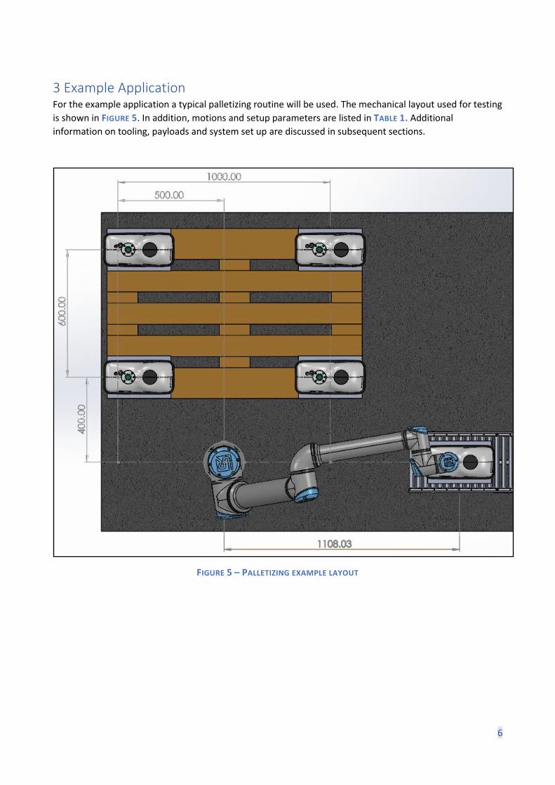
3 Example Application For the example application a typical palletizing routine will be used. The mechanical layout used for testing
is shown in FIGURE 5. In addition, motions and setup parameters are listed in TABLE 1. Additional
information on tooling, payloads and system set up are discussed in subsequent sections.
FIGURE 5 – PALLETIZING EXAMPLE LAYOUT

7
TABLE 1 – PALLETIZING EXAMPLE MOTION CRITERIA
X [mm] Y [mm] Z [mm] Rx [deg] Ry [deg] Rz [deg]
Pick 1108,03 0 200 -180 0 -90
Corner 1 -500 1000 -200 -180 0 0
Corner 2 -500 400 -200 -180 0 0
Corner 3 500 400 -200 -180 0 0
Corner 4 500 1000 -200 -180 0 0
Pallet Pattern 4x4 (16 cycles); 1 layer
Linear Moves Joint Moves
Speed 2,000 mm/s 120 ⁰/s
Acceleration 1,500 mm/s2 240⁰/s2
Approach offset
125mm
Dwell at Pick/ Place
1.00s
Robot Limit Safety Settings

8
3.1 How to Utilize the Payload Curve The payload curve in FIGURE 6 shows the graphical boundary of the CoG offset compared to the maximum allowed payload. Inside of the shaded boundary allows for unconstrained robot motion, that is the robot can be expected to perform at its rated speed and acceleration. Comparatively, robot motion outside of this boundary will be subject to automatic reductions in robot speed and acceleration. The graph highlights the increased payload rating up to 12.5kg on the UR10e.
FIGURE 6 – PAYLOAD CURVE FROM UR10E USER MANUAL
3.1.1 Calculating the Center of Gravity offset The center of gravity (CoG) location can be calculated in several ways. Typically, this is done via a 3D modeling program, such as SolidWorks, or with the native payload wizard from PolyScope. The Payload Wizard process is outlined in Section 24.3.3 of the User Manual. However, in some cases, utilizing the wizard with larger payloads is not feasible. For those instances, the CoG location and other payload should be set as close as possible to the exact scenario that the robot will encounter.

9
3.1.2 How to Generate Payload Data in SolidWorks In this use case, we utilize SolidWorks Mass Properties evaluation tool to generate the data. TABLE 2 shows
the mass properties of the tool and the payload independently. The tool mass properties are given from the
supplier’s website. The part is a generic rectangle measuring 200mm x 300mm x 280mm.
TABLE 2 – MOI DATA FOR PALLETIZING EXAMPLE
Palletizing Application example UR10e – 12.5kg
Total Payload 12.5 kg
Tool Load 2.17 kg CoG location (from Tool Flange) X = 0mm Y = -71.95mm Z = 60.16mm MOI
I X Y Z
X 0.01826 0 0
Y 0 0.0055 0
Z 0 0 0.0197
Part 10.33 kg CoG location (At volumetric center) X = 0mm Y = 0mm Z = 0mm MOI (kg*m2)
I X Y Z
X 0.1019 0 0
Y 0 0.1120 0
Z 0 0 0.1450

10
Shown in FIGURE 7 is a 3D model generated from SolidWorks. The CoG locations for each individual
component indicated by the yellow and black fiducials. The CoG location for the combined components is
referenced by the white and black fiducial. Also noted is the direction of gravity.
FIGURE 7 – MODEL OF TOOLING AND PAYLOAD COG LOCATION FROM SOLIDWORKS

11
The associated mass properties can be calculated directly through the Mass Properties evaluation tool.
Once units of measure in the software are configured, the values generated are used for payload settings.
The MOI settings are accessed via the “Options…” button in the main window, shown in FIGURE 8. Once the
units are defined, the mass properties for the model are shown in the main window, see FIGURE 9. This data
can be directly entered into the inertia matrix for that given load case.
FIGURE 8 – OPTIONS SETTINGS FOR CORRECT UNITS
FIGURE 9 – MODEL MASS PROPERTIES EVALUATION

12
From FIGURE 10 the CoG location is located at (0, -0.0546, 0.2567) meters in the Tool Flange coordinate system. These values are inserted into a sketch as the vertical (dz) and horizontal (dy) CoG components shown in FIGURE 7. The resultant vector is shown as a radius from the tool flange origin (262.48mm).
FIGURE 10 – COG LOCATION SKETCHED ONTO MODEL

13
3.2 Restricting Tool Flange Orientation In this section, tool flange orientation and the effects of restricting this orientation are described. The goal
when designing for higher payloads is to limit the torque about the origin of the tool flange. As a result, a
smaller perpendicular CoG offset in relation to gravity decreases this value. In FIGURE 11, the maximum
torque acting upon the tool flange is shown with this given load case. If this case is plotted onto the
payload curve, the payload would be outside of the shaded region.
FIGURE 11 – COG LOCATION SKETCHED ONTO MODEL
3.2.1 Tool Direction Feature The tool direction feature is used to restrict angles of the tool frame. As part of the safety configuration, it
is advised to apply these configurations prior to programming. Once properly configured this feature
prevents inadvertent stops or faults. For more information on this command, see Section 21.15 of the User
Manual. In this example, we limit the pan and tilt of the tool flange to +/- 15 degrees, as shown in FIGURE
12.
FIGURE 12 – TOOL DIRECTION CONFIGURATION

14
3.3 How to Reference Payload Curve with of CoG offset Having the vertical and horizontal components of the CoG offset location, we can now apply them to the payload chart. For the example application, the tool flange will remain in the orientation shown in FIGURE
10 based on the conclusion outlined in Section 3.1.2. Knowing this, the component of the CoG offset location that is perpendicular to gravity is Y component (54.64mm). Plotting the values of 12.5kg and 54.64mm onto the payload curve shows the application remains within the shaded region of the graph.
FIGURE 13 – MAXIMUM PAYLOAD FOR HORIZONTAL COMPONENT OF COMBINED PAYLOAD

15
3.4 Palletizing Application Results In this section, the results of the simulated cycles are shown from the UR Offline Simulator tool. The UR Offline Simulator can be found on the UR support site. The safety settings and criteria for motion are referenced in TABLE 1. The benchmark case uses the payload defined in Section 3. The results from the simulation are outlined in TABLE 3.
Palletizing UR10e
Benchmark case
Total Payload 12.5 kg
Tool Load 2.17 kg CoG location (from Tool Flange) X = 0mm Y = -71.95mm Z = 60.16mm MOI
I X Y Z
X 0.01826 0 0
Y 0 0.0055 0
Z 0 0 0.0197
Combined Load (Tool and
Part)
12.5 kg CoG location X = 0mm Y = -54.64mm Z = 256.73mm Horizontal CoG component: 54.64mm MOI
I X Y Z
X 0.2654 0 0
Y 0 0.2088 0
Z 0 0 0.1324
Capacity 7.9 cases/ minute ~7.594 seconds/ cycle
TABLE 3 – PALLETIZING EXAMPLE SIMULATION RESULTS

16
Intentionally left blank end of document


