Application guide ECOLEAN - EAC/EARlenergy.hu/dokuk/termekek/11/k6cv8y9a.pdf · Providing indoor...
40
Providing indoor climate comfort ECOLEAN - EAC/EAR Application guide MSL76E-0104 12-2006
Transcript of Application guide ECOLEAN - EAC/EARlenergy.hu/dokuk/termekek/11/k6cv8y9a.pdf · Providing indoor...

Providing indoor climate comfort
ECOLEAN - EAC/EAR
Application guide
MSL76E-0104 12-2006

1
Introduction and description of the components .................................................................. 2
Available options .................................................................................................................. 5
Performance tables for the units without air ducts:
Axial fan units ....................................................................................................................... 7
Performance tables for the units with air ducts:
Axial fan units ..................................................................................................................... 12
High static pressure units ................................................................................................... 12
Performance units with low water temperature kit ............................................................. 14
Technical data .................................................................................................................... 15
Electrical data .................................................................................................................... 17
Water pressure drop .......................................................................................................... 18
Dimensional data ............................................................................................................... 20
Dimensional data, weight and service areas ..................................................................... 22
Noise levels ....................................................................................................................... 23
Operating limits .................................................................................................................. 25
Unit installation inside ........................................................................................................ 27
Hydraulic equipment .......................................................................................................... 28
Draft specifications ............................................................................................................ 37
The specifications and technical characteristics in this booklet are given for information purposes. The manufacturer reserves the right to modify them without priornotice or obligation to modify in a similar manner, the equipments previously supplied.
CONTENTSCONTENTS
Lennox have been providing environmental solutions since 1895, our range of EcoLeanTM reversible chillers continues to meetthe standards that have made LENNOX a household name. Flexible design solutions to meet YOUR needs and uncompromisingattention to detail. Engineered to last, simple to maintain and Quality that comes as standard.Information on local contacts at www.lennoxeurope.com.
All the technical and technological information contained in this manual, including any drawing and technical descriptions providedby us, remain the property of Lennox and must not be utilised (except in the operation of this product), reproduced, issued to ormade available to third parties without the prior written agreement of Lennox.
Our company's products comply with European standards.
The manufacturing of EcoLeanTM answers to ISO9001 control quality system.

In order to ensure conformity of finished product with the customers' order and the perfect refrigeration and electricaloperation of the unit, the EcoLeanTM chillers are systematically tested in the test station before shipping.
With low dimensions and quiet operation, the EcoLeanTM chillers make use of the finest in technology to satisfy thestrictest reliability and safety requirements.
EcoLeanTM units are equipped with hermetic scroll type compressors .
- STANDARD VERSION UNIT• Piping and inlet/outlet connections.
- HYDRAULIC VERSION UNIT• Piping and inlet/outlet connections.• Water pump.• Expansion vessel.• Collapsible water filter.• Safety valve.• Manometer.• Flow switch.
STANDARD ACCESSORIES FITTED SUPPLIED ON THE VARIOUS VERSIONS
EA C 035 1 S K HY FP
K: Refrigerant R407CA: Refrigerant R22 (*1)
Number of compressors
Aprox. nominal capacity expressed in kW
High static pressuremodels:FP: 0091 to 0211 version modelsFP1: 0251 to 1303 version models and available static pressure sown to 120 PaFP2: 0251 to 1303 version models and available static pressure sown to 250 or 350 Pa
--- : Standard versionHY: Hydraulic versionHN: Hydronic version
C: CoolingR: Heating
EcoLeanTM
Type of compressorS: Scroll
- HYDRONIC VERSION UNIT• Piping and inlet/outlet connections.• Water pump.• Expansion vessel.• Collapsible water filter.• Safety valve.• Manometer.• Flow switch.• Water tank.
FAN STATIC PRESSURES
- STANDARD VERSION UNIT (all models)• Available static pressure sown to 50 Pa.
- FP VERSION UNIT (0091 to 0211 models)• Available static pressure sown to 200 Pa.
- FP1 VERSION UNIT (0251 to 1303 models)• Available static pressure sown to 120 Pa.
- FP2 VERSION UNIT (0251 to 1303 models)• Available static pressure sown to 250 or 350 Pa.
(*1) R22 is only for units used outside the EEC.
2
INTRODUCTION - DESCRIPTION OF COMPONENTS
EXAMPLES OF UNITS RANGES DESIGNATIONS

CHASSIS
- Rigid, hot dipped galvanized chassis.- Polyester paint - Color RAL 9002.- Unit lifting and handling via the base frame.
COMPRESSOR
- Scroll type.- Suction gas cooled integral motor.- Crankcase heater.- Direct on line start.- Mounted on high efficiency cellular polyurethane vibration absorbers.
PLATE EXCHANGER
- Stainless steel plate brazed.- Thermal insulation by top grade 10 mm plastic foam.
OUTDOOR EXCHANGER
- Expanded copper tubes and high efficiency fins.
FANS
- Standard version: axial fans 900 rpm, direct coupling- FP version: centrifugal fans 1450 rpm, direct coupling- FP1 version: axial fans 1450 rpm, direct coupling 0251 to 0812 models, axial fans 900rpm ,direct coupling 1003 to1303 models.- FP2 version: axial fans "short case" 1450 rpm, direct coupling.
REFRIGERATION CIRCUITS ACCESSORIES
Welded and hermetically sealed and including thefollowing components:- Expansion valve- Filter drier- High-pressure switch with automatic reset- Low-pressure switch with automatic reset (Heat pump units incorporate two of them, one for cooling only cycle and other for heat pump cycle).- Four-way valve (heat pump units only).- Liquid device (heat pump units only).
ELECTRICAL PANEL
- Unit wiring in compliance with standard EN 60204-1.- IP 54 water protection.- Protection fuses for compressor, fan and water pump.- Compressor, fan and water pump working contactors- Crankcase heater.- Terminal block and wiring for power supply to the unit.
CONTROL
- Model: Climatic R 200/400.- Control and check by microprocessor.- Reading of water and refrigerant temperatures.- Alarm signaling.- Diagnostic per circuit.- Adjustment of temperature set points and parameters adapted. for operating conditions- Hour counter and daily balance of operating time for each compressor by "first in/first out" permutation (units with two compressors).- Possibility of remote alarm signals. (Option for some models).- Antifreeze protection.- Fan speed control.
3
INTRODUCTION - DESCRIPTION OF COMPONENTS
set
mode
on off
• ••
• •
DISPLAY (STANDARD)(Incorporated in the unit)
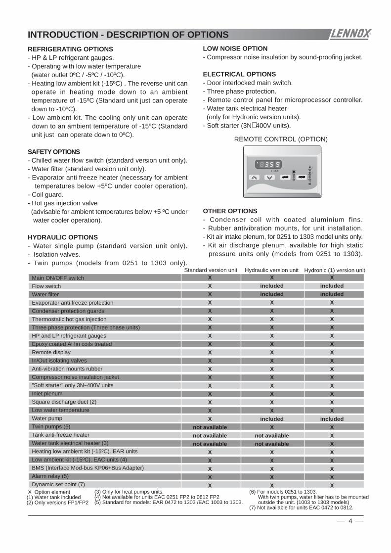
REFRIGERATING OPTIONS- HP & LP refrigerant gauges.- Operating with low water temperature (water outlet 0ºC / -5ºC / -10ºC).- Heating low ambient kit (-15ºC) . The reverse unit can operate in heating mode down to an ambient temperature of -15ºC (Standard unit just can operate down to -10ºC).- Low ambient kit. The cooling only unit can operate down to an ambient temperature of -15ºC (Standard unit just can operate down to 0ºC).
SAFETY OPTIONS- Chilled water flow switch (standard version unit only).- Water filter (standard version unit only).- Evaporator anti freeze heater (necessary for ambient temperatures below +5ºC under cooler operation).- Coil guard.- Hot gas injection valve (advisable for ambient temperatures below +5 ºC under water cooler operation).
HYDRAULIC OPTIONS- Water single pump (standard version unit only).- Isolation valves.- Twin pumps (models from 0251 to 1303 only).
LOW NOISE OPTION- Compressor noise insulation by sound-proofing jacket.
ELECTRICAL OPTIONS- Door interlocked main switch.- Three phase protection.- Remote control panel for microprocessor controller.- Water tank electrical heater (only for Hydronic version units).- Soft starter (3N∼400V units).
OTHER OPTIONS- Condenser coil with coated aluminium fins.- Rubber antivibration mounts, for unit installation.- Kit air intake plenum, for 0251 to 1303 model units only.- Kit air discharge plenum, available for high static pressure units only (models from 0251 to 1303).
Hydraulic version unit Hydronic (1) version unitStandard version unitMain ON/OFF switchFlow switchWater filterEvaporator anti freeze protectionCondenser protection guardsThermostatic hot gas injectionThree phase protection (Three phase units)HP and LP refrigerant gaugesEpoxy coated Al fin coils treatedRemote displayIn/Out isolating valvesAnti-vibration mounts rubberCompressor noise insulation jacket"Soft starter" only 3N~400V unitsInlet plenumSquare discharge duct (2)Low water temperatureWater pumpTwin pumps (6)Tank anti-freeze heaterWater tank electrical heater (3)Heating low ambient kit (-15ºC). EAR unitsLow ambient kit (-15ºC). EAC units (4)BMS (Interface Mod-bus KP06+Bus Adapter)Alarm relay (5)Dynamic set point (7)
Xincludedincluded
XXXXXXXXXXXXXX
includedX
not availablenot available
XXXXX
XXXXXXXXXXXXXXXXXX
not availablenot availablenot available
XXXXX
Xincludedincluded
XXXXXXXXXXXXXX
includedXXXXXXXX
X Option element(1) Water tank included(2) Only versions FP1/FP2
(3) Only for heat pumps units.(4) Not available for units EAC 0251 FP2 to 0812 FP2(5) Standard for models: EAR 0472 to 1303 /EAC 1003 to 1303.
(6) For models 0251 to 1303. With twin pumps, water filter has to be mounted outside the unit. (1003 to 1303 models)(7) Not available for units EAC 0472 to 0812.
4
REMOTE CONTROL (OPTION)
2
1x 1000
INTRODUCTION - DESCRIPTION OF OPTIONS

MAIN ON/OFF SWITCHLocated at the electrical box of the unit.
FLOW SWITCH (included on Hydraulic and Hydronicversions).The flow switch stops the unit if water flow is lower than theminimum.
WATER FILTER (included on Hydraulic and Hydronicversions).The water filter must be fitted in the water inlet of the unit,it protects the unit against particles (greater than1 mm) getting inside the water circuit, and prevents thewater interchanger gets dirty.NOTE: IT IS NECESSARY TO FIT A WATER FILTER INTHE WATER INLET OF THE UNIT
EVAPORATOR ANTI FREEZE PROTECTIONThe evaporator anti freeze heater prevents the waterexchange from low temperatures.
CONDENSER PROTECTION GUARDSThe condenser coil protection grill prevents light damageto the coil when shipping and when installed. It cannotprotect against very heavy impacts.
THERMOSTATIC HOT GAS INJECTIONSupplies hot gas which is injected into the evaporator gasto increase the suction pressure if the chilled watertemperature falls to low. It can be used to allow the unit tooperate at reduced capacity, if the water temperature fallsbelow the set point (5ºC). It is controlled via themicroprocessor controller ON at (5ºC) and OFF (6ºC) forexample. This option is NOT available for units selectedwith low water temperature option.
THREE PHASE PROTECTIONLocated at the electrical box of the unit, it assures that unitwill not begin operation if connection phases of compressorare not correct. Should this occur, then just switch twophase connections.
HP AND LP RERRIGERANT GAUGESVisualize the high and low pressures of the refrigerantcircuit.
EPOXY COATED ALUMINIUM FIN COILS TREATEDSpecial protection of the aluminium condenser coil fins, togive improved protection from aggressive externalenvironmental conditions.
REMOTE DISPLAYIt controls and shows the unit's operating, it may be installeduntil 50 m from the unit.
IN/OUT ISOLATING VALVESTo fit at inlet and water outlet of the unit. Isolating the unitfrom water circuit, so service and maintenance of the unitwill be easier.For units EAC 1003-1303 SKHN this option includes anothervalve in order to isolate the buffer tank.
ANTI-VIBRATION MOUNTS RUBBERTo install under the unit, to avoid transmission of vibrations,to the floor where unit is installed, while unit is operating.
COMPRESSOR NOISE INSULATION JACKETEach compressor is fitted with a compressor acoustic jacketthis provides attenuation of the compressor noise thatradiates from the unit when in operation.
WATER PUMP (included on Hydraulic and Hydronicversions)
TWIN PUMPS KIT (models from 0251 to 1303 only)It is formed by two-water pump mounted on parallel andwith same characteristics as the single one. Only one pumpis working the other remains on stand by.When the water pump, which is operating cuts out, andthe pump turns off, automatically starting the water pumpon stand by.It is possible to select which one of the pumps we want tobe working through an external switch supplied with the kit.With the twin pumps, the available static pressure willdecrease 5% from the available static pressure with onewater pump only.
SOFT STARTER (for 3N~400V units only)It is an electronic element, which reduces the peakcompressor starting current up to 40%.
INLET PLENUM (models from 0251 to 1303 only)It is a accessory for adapting the condenser air intaketo accept a duct.
SQUARE DISCHARGE DUCT (FP1 and FP2 unitversions and models from 0251 to 1303 only).It is formed by 1 or 2 square frames, for adaptingdischarge air from the unit to a square duct.
NOTE: All the options will be supplied and mounted in the unit, except the water filter, water isolationvalves, rubber antivibration mounts, remote controller and air intake plenum supplied to mount in themoment of installation.
5
AVAILABLE OPTIONS

6
LOW WATER TEMPERATURENecessary for water outlet temperatures below +5ºCThere are three different kits, which depend for selecting on the water outlet temperature desired, as the following table shows:
An immersion heater can be supplied complete with safetythermostat and pressure switch fitted in the buffer tank, or ananti-freeze and supplementary heater (heat pump units only).
Tank Anti-freeze heater: It starts when water temperature inthe buffer tank is lower than + 5ºC (Not for units with low watertemperature kit).
Water tank electrical heater: Heat pump units only. The heaterworks as anti-freeze heater as explained before and assupplementary heater, when inlet warm water reaches atemperature below a value selected (example: 30 ºC) throughan independent thermostat included.
TANK ANTI-FREEZE HEATER AND WATER TANK ELECTRICAL HEATER (available only for Hydronic version)
BMS (Interface Mod-bus KP06+Bus Adapter)It is possible to connect several units with a communicationsystem (MOD BUS Protocol).
ALARM RELAYIt is a free voltage contact which indicates a general alarm inthe unit.
DYNAMIC SET POINT(Not available for units EAC 0472 to 0812)It changes cooling and heating set point according ambienttemperature (an extra sensor must be installed).
LOW AMBIENT KIT (-15ºC)(Not available for EAC 0251 FP2 to EAC 0812 FP2)- With this option, the cooling only units (EAC) can operatewith ambient temperature below 0ºC (standard unit limit) downto (-15ºC).- For models EAC 1003 to 1303 there are 2 versions: * Low ambient kit (-15ºC) Air conditioner (Comfort applications). When the ambient temperature is 0ºC, one circuit is disabled, only the other circuit can operate below 0ºC down to (-15ºC). * Low ambient kit (-15ºC) Process (Industrial applications). Both circuits can operate below 0ºC down to (-15ºC).
HEATING LOW AMBIENT KIT (-15ºC)With this option heat pump units (EAR) on heating mode canoperate with ambient temperature below (-10ºC) (standardunit limit) down to (-15ºC).
1195
149
1195
790
416
605
416
848
101
246
Square discharge duct
Inletplenum
980
848
31
101
Inletplenum
Square discharge duct 848x848
149
1195
1209
416
790
790
416
1195
101
246
10162
1011195
416
0251 to 0431 MODELS
0472 to 0812 MODELS
1003 to 1303 MODELS
106
324
149
62
416
1495
1170
1140
1140Inletplenum
Square discharge duct 848x848
1041420
416
1495
600
106
Models
Voltage v
0472/08120251/0431
Tank anti-freeze heaterWater tank electrical heater*
0091/0211
kW
1003/1303
3~230V - 3~400V2,252,25129
1N~230V
2,256
624
3~400V
THE POWER INPUT IS:
(*) Heat pump units only
kW
Application duty on the water outlet temperatureKIT LOW WATER TEMPERATURE 0ºCKIT LOW WATER TEMPERATURE -5ºCKIT LOW WATER TEMPERATURE -10ºC
For water temperatures below 5ºC to 0ºCFor water temperatures below 0ºC to -5ºCFor water temperatures below -5ºC to -10ºC
Denomination
AVAILABLE OPTIONS

7
AXIAL FAN UNITS COOLING MODE
MODELS Air inlet temperatureºCWater outlettemperature 28°C 30°C 32°C 35°C 40°C 45 °C
6
7
9
11
EAC 0291EAR 0291
EAC 0251EAR 0251
EAC 0091EAR 0091
EAC 0111EAR 0111
EAC 0151EAR 0151
EAC 0191EAR 0191
EAC 0211EAR 0211
EAC 0351EAR 0351
EAC 0431EAR 0431
7
9
11
6
7
9
11
6
7
9
11
6
7
9
11
6
7
9
11
6
7
9
11
6
7
9
11
6
7
9
11
6
QoQo P P Qo P P Qo P Qo PQo
46,18 14,96 46,39 15,17 45,16 15,46 43,94 15,75 41,32 17,40 39,49 19,08
9,11
8,92
2,98
2,92
9,31
9,09
3,00
2,95
9,06
8,85
3,05
3,01
8,84
8,58
3,09
3,08
8,14
7,91
3,43
3,41
7,61
7,40
3,77
3,74
11,25
9,8310,56
3,59
3,063,13
11,47
9,9610,60
3,62
3,093,18
11,16
9,6910,32
3,70
3,143,24
10,82
9,4210,04
3,79
3,203,30
9,98
8,799,45
4,19
3,533,65
9,33
8,329,03
4,59
3,884,00
13,31
11,4912,40
3,85
3,663,76
13,38
11,7512,56
3,91
3,683,79
13,02
11,4212,22
3,98
3,753,86
12,67
11,211,88
4,06
3,783,93
11,91
10,2611,09
4,48
4,214,34
11,39
9,6010,49
4,91
4,634,77
14,86
13,4813,77
4,87
4,664,75
15,05
13,7414,08
4,92
4,704,77
14,65
13,3713,69
5,01
4,794,86
14,24
12,9613,4
5,10
4,914,93
13,29
11,9612,30
5,63
5,435,46
12,57
11,1811,50
6,18
5,956,00
17,91
15,95
17,54
6,15
4,99
6,04
18,31
16,03
17,87
6,18
5,06
6,09
17,81
15,60
17,39
6,29
5,16
6,21
17,4
15,18
16,86
6,35
5,26
6,36
15,99
14,28
15,56
7,07
5,81
7,04
14,96
13,64
14,54
7,78
6,37
7,71
19,36
19,33
20,756,70
6,31
6,4719,73
19,58
20,856,75
6,37
6,5619,20
19,05
20,306,89
6,49
6,6918,62
18,52
19,757,06
6,61
6,8117,18
17,28
18,577,81
7,30
7,5316,05
16,35
17,748,56
8,01
8,25
22,91
19,7721,34
7,18
6,827,00
23,01
20,2221,62
7,28
6,867,07
22,41
19,6621,03
7,42
6,987,20
21,80
19,220,45
7,56
7,067,33
20,50
17,6619,08
8,35
7,858,10
19,59
16,5218,05
9,15
8,638,89
25,70
23,3123,81
9,14
8,798,90
26,03
23,6924,34
9,23
8,878,94
25,33
23,0123,67
9,40
9,059,10
24,63
22,3123,00
9,57
9,229,27
22,98
20,6321,26
10,57
10,1710,22
21,74
19,3619,89
11,60
11,1211,23
27,95
27,59
27,36
10,01
9,37
9,89
28,58
27,71
27,81
10,06
9,50
9,98
27,79
26,98
27,02
10,23
9,69
10,18
27,00
26,25
26,19
10,43
9,87
10,37
24,96
24,69
24,22
11,50
10,90
11,44
23,35
23,59
22,72
12,64
11,95
12,51
32,42
30,1732,39
11,49
10,2810,55
32,96
30,5632,53
11,60
10,3810,69
32,02
29,7331,68
11,83
10,5710,90
31,03
28,9130,82
12,05
10,7611,10
28,70
26,9728,98
13,29
11,8912,26
26,93
25,5227,69
14,53
13,0613,44
38,38
33,1235,75
12,25
11,6311,95
38,56
33,8736,21
12,43
11,6912,07
37,54
32,9335,24
12,66
11,8912,29
36,52
32,0034,26
12,90
12,1212,51
34,35
29,5831,97
14,25
13,3613,82
32,82
27,6730,25
15,62
14,6915,17
43,01
39,0139,85
14,59
14,0314,20
43,57
39,6540,75
14,73
14,1614,27
42,39
38,5239,62
15,00
14,4414,52
41,22
37,3438,50
15,27
14,7214,80
38,46
34,5335,59
16,88
16,2316,32
36,39
32,4033,29
18,53
17,7517,94
Qo : Net cooling capacity in kW
P : Total power input in kW (compressor and fan motor)
Fouling factor: 0,44 m²C/kW
Water ∆T = 5 ºC
Nominal conditions
Units are tested and rated in accordance with Eurovent standards
PERFORMANCE TABLES - UNITS WITHOUT AIR DUCT

8
AXIAL FAN UNITS COOLING MODE
MODELS
Air inlet temperatureºCWater outlettemperature
Qo P Qo P Qo P Qo P Qo P Qo P
28°C 30°C 32°C 35°C 40°C 45 °C
6
7
9
11
EAC 0472EAR 0472
EAC 0552EAR 0552
EAC 0672EAR 0672
EAC 0812EAR 0812
7
9
11
6
7
9
11
6
7
9
11
6
Qo : Net cooling capacity in kW
P : Total power input in kW (compressor and fan motor)
Fouling factor : 0,44 m²C/kW
Water ∆T = 5 ºC
Nominal conditions
6
7
9
11
EAC 1003EAR 1003
EAC 1103EAR 1103
EAC 1203EAR 1203
EAC 1303EAR 1303
7
9
11
6
7
9
11
6
7
9
11
6
45,5444,58
16,3116,12
46,5745,31
45,2944,03
16,6816,59
44,0042,67
17,0016,91
40,6839,47
18,7418,65
38,0537,03
20,6020,38
52,08
49,16
52,78
18,68
16,76
17,19
52,94
49,79
53,02
51,43
48,45
51,62
19,22
17,23
17,76
49,85
47,11
50,22
19,59
17,54
18,09
46,11
43,95
47,23
21,61
19,38
19,99
43,26
41,59
45,13
23,62
21,28
21,91
61,66
53,2057,43
19,92
18,9019,42
61,94
54,4058,17
60,30
52,9056,60
20,58
19,3319,97
58,66
51,4055,03
20,97
19,7020,33
55,17
47,5251,35
23,16
21,7222,46
52,72
44,4548,58
25,39
23,8724,66
69,83
63,3364,69
23,72
22,8223,09
70,73
64,3766,15
68,82
62,5364,32
24,39
23,4823,61
66,91
60,6162,50
24,83
23,9324,06
62,43
56,0657,78
27,43
26,3926,52
59,07
52,6054,04
30,12
28,8529,16
78,15
74,97
76,5028,69
24,33
28,3579,91
75,31
77,7677,71
73,32
75,5429,34
25,14
29,1875,50
71,33
73,2229,90
25,61
29,7469,80
67,08
67,7232,96
28,29
32,7965,29
64,10
63,5436,24
31,01
35,85
84,36
90,57
29,48
30,23
85,44
90,98
83,14
88,57
30,31
31,24
80,84
86,17
30,86
31,83
75,42
81,04
34,09
35,16
71,36
77,44
37,43
38,54
16,4016,27
18,85
16,92
17,43
20,20
19,0019,61
23,95
23,0223,21
28,84
24,67
28,61
29,77
30,65
91,2989,37
33,7633,36
93,3590,84
90,7888,25
34,5234,33
90,0087,29
34,4934,30
83,2180,73
38,0237,83
77,8375,74
41,8041,36
102,34
98,55
105,8036,87
34,69
35,57104,02
99,82
106,28101,06
97,12
103,4737,94
35,67
36,7697,95
96,36
102,7238,29
35,60
36,7190,60
89,90
96,6042,23
39,33
40,5685,00
85,07
92,3146,17
43,17
44,45
121,15
104,54
112,8539,32
37,31
38,34121,70
106,90
114,30118,49
103,95
111,2240,63
38,16
39,42115,28
101,00
108,1440,98
38,50
39,73108,41
93,37
100,8945,27
42,44
43,90103,60
87,34
95,4749,62
46,66
48,19
126,65
114,86117,33
44,04
42,3642,86
128,28
116,74119,98
124,82
113,42116,67
45,28
43,5843,83
122,59
111,05114,50
45,19
43,5543,79
114,38
102,71105,86
49,93
48,0348,28
108,23
96,3699,01
54,82
52,5153,07
128,82
135,97
126,11
47,45
45,16
46,89
131,73
136,59
128,18
128,10
132,98
124,53
48,52
46,67
48,25
127,00
130,68
123,17
48,48
46,61
48,22
117,41
122,90
113,92
53,45
51,49
53,17
109,82
117,44
106,88
58,75
56,44
58,13
139,06
149,29
48,76
50,00
140,85
149,97
137,05
146,01
50,13
51,66
135,97
144,95
50,03
51,60
126,86
136,32
55,28
57,01
120,04
130,27
60,69
62,49
33,9333,66
37,21
35,02
36,07
39,86
37,50
38,71
44,47
42,7443,08
47,69
45,79
47,32
49,23
50,70
Units are tested and rated in accordance with Eurovent standards
PERFORMANCE TABLES - UNITS WITHOUT AIR DUCTPERFORMANCE TABLES - UNITS WITHOUT AIR DUCT

AXIAL FAN UNITS HEATING MODE
11750-5-10
EAR 0091
Qc
30°C
P
11750-5-10
EAR 0111
11750-5-10
EAR 0151
11750-5-10
EAR 0191
11750-5-10
EAR 0211
Qc
35°C
P Qc
40°C
P Qc
45°C
P Qc
50°C
P
11750-5-10
EAR 0251
11750-5-10
EAR 0291
ºCAmbient airtemperature
MODELS
Hot water outlet temperature
6,10 2,247,24 2,278,03 2,319,07 2,369,55 2,38
10,53 2,43
7,52 2,958,92 3,009,90 3,0511,19 3,1211,78 3,1512,99 3,21
8,91 3,5010,57 3,5611,73 3,6113,25 3,7013,95 3,7315,39 3,80
11,85 4,5214,07 4,6115,62 4,6817,64 4,8018,57 4,8520,48 4,95
13,41 5,1015,92 5,1917,67 5,2819,96 5,4121,01 5,4623,17 5,57
5,89 2,427,03 2,477,81 2,518,82 2,579,29 2,60
10,24 2,65
7,26 3,198,67 3,259,63 3,31
10,88 3,4011,46 3,4412,63 3,51
8,61 3,7910,27 3,8611,41 3,9312,89 4,0313,57 4,0714,97 4,15
11,45 4,8913,66 4,9915,18 5,0917,16 5,2318,06 5,2919,92 5,41
12,96 5,5215,46 5,6317,18 5,7419,41 5,8920,44 5,9622,54 6,09
5,57 2,656,77 2,697,59 2,738,66 2,819,15 2,84
10,14 2,91
6,87 3,498,34 3,559,36 3,61
10,68 3,7111,28 3,7512,50 3,84
8,14 4,149,88 4,2011,09 4,2812,65 4,3913,36 4,4514,81 4,55
10,84 5,3513,15 5,4414,76 5,5416,84 5,7017,78 5,7719,71 5,92
12,26 6,0314,88 6,1316,70 6,2419,05 6,4220,12 6,5022,30 6,66
6,53 2,947,39 2,998,51 3,078.96 3,379,98 3,18
8,05 3,879,12 3,94
10,49 4,0511,0 4,45
12,31 4,20
9,54 4,5910,80 4,6712,43 4,8013,1 5.28
14,58 4,98
12,69 5,9414,37 6,0416,54 6,2217,4 6,82
19,40 6,47
14,36 6,7016,26 6,8118,71 7,0119,7 7,70
21,96 7,28
6,97 3,218,15 3,318,66 3,359,68 3,44
8,60 4,2410,05 4,3610,69 4,4211,93 4,55
10,19 5,0211,91 5,1712,66 5,2414,14 5,39
13,56 6,4915,84 6,6916,85 6,7918,81 6,99
15,34 7,3217,93 7,5519,06 7,6621,29 7,88
18,63 7,1822,11 7,3224,54 7,4527,72 7,6429,18 7,7332,18 7,90
18,00 7,7621,47 7,9323,86 8,0926,96 8,3128,38 8,4231,30 8,62
17,03 8,4820,67 8,6323,20 8,7926,46 9,0627,94 9,1830,97 9,42
19,95 9,4222,59 9,5925,99 9,8827,50 10,0030,49 10,29
21,30 10,3124,90 10,6326,48 10,7929,56 11,12
16,26 6,3819,30 6,5021,41 6,6224,19 6,7925,46 6,87
15,71 6,8918,74 7,0420,82 7,1823,53 7,3924,77 7,48
14,86 7,5318,04 7,6620,25 7,8123,09 8,0524,39 8,16
17,41 8,3719,71 8,5222,68 8,7824,00 8,90
18,59 9,1621,73 9,4523,11 9,59
28,09 7,02 27,32 7,66 27,03 8,38 26,61 9,15 25,80 9,88
--- --- --- ---
--- ---
--- --- --- ---
--- ---
--- --- --- ---
--- ---
--- --- --- ---
--- ---
--- --- --- ---
--- ---
--- --- --- ---
--- ---
--- --- --- ---
--- ---
Units are tested and rated in accordance with Eurovent standards
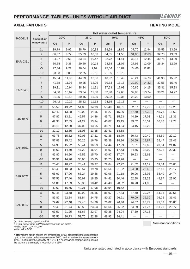
Note: with the option heating low ambient kit (-15ºC), it is possible the unit operationup to a hot water outlet temperature of 50ºC, and an ambient temperature of -15ºC. To calculate the capacity at -15ºC, it is necessary to extrapolate figures onthe table and then apply a reduction of a 15%.
Qc : Net heating capacity in kWP : Total power input in kW (compressor and fan motor)Fouling factor : 0,44 m²C/kWWater ∆T = 5 ºC
9
PERFORMANCE TABLES - UNITS WITHOUT AIR DUCT
Nominal conditions
AXIAL FAN UNITS HEATING MODE
ºCAmbient airtemperature
MODELS
11
7
5
0
-5
-10
EAR 0472
Qc
30°C
P
11
7
5
0
-5
-10
EAR 0552
11
7
5
0
-5
-10
EAR 0672
11
7
5
0
-5
-10
EAR 0812
Qc
35°C
P Qc
40°C
P Qc
45°C
P Qc
50°C
P
11
7
5
0
-5
-10
EAR 0351
11
7
5
0
-5
-10
EAR 0431
Hot water outlet temperature
32,17 12,35
38,19 12,60
42,38 12,85
47,87 13,21
50,40 13,38
55,59 13,72
43,69 16,65
51,86 17,03
57,55 17,40
65,01 17,96
68,43 18,23
75,48 18,77
53,51 20,73
63,51 21,25
70,49 21,74
79,62 22,48
83,82 22,84
92,45 23,58
31,08 13,35
37,08 13,65
41,22 13,94
46,57 14,36
49,02 14,55
54,06 14,93
42,21 17,98
50,35 18,42
55,97 18,85
63,24 19,48
66,57 19,78
73,41 20,37
51,70 22,38
61,67 22,97
68,55 23,53
77,46 24,36
81,54 24,75
89,92 25,55
29,41 14,58
35,71 14,84
40,07 15,15
45,71 15,63
48,27 15,86
53,49 16,31
39,94
48,48
54,41
62,06
65,54
72,64
48,92 24,41
59,38 24,94
66,64 25,52
76,02 26,46
80,27 26,91
88,97 27,83
46,78 21,83
52,98 22,28
60,96 23,05
64,50 23,43
71,52 24,19
57,30 27,18
64,89 27,77
74,67 28,77
79,00 29,30
87,60 30,27
49,97 23,90
58,40 24,74
62,10 25,17
69,34 26,05
61,20 29,77
71,53 30,86
76,06 31,41
84,93 32,56
19,62
20,02
20,46
21,18
21,52
22,22
34,45 16,20
39,02 16,51
44,89 17,03
47,50 17,30
52,67 17,79
36,80 17,73
43,01 18,31
45,73 18,60
51,06 19,20
36,91 14,20
43,82 14,50
48,63 14,79
54,93 15,22
57,82 15,42
63,78 15,82
35,66 15,35
42,55 15,70
47,29 16,04
53,44 16,53
56,25 16,76
62,03 17,21
33,75
40,97
45,97
52,44
55,38
61,38
39,53 18,63
44,76 18,99
51,51 19,60
54,50 19,87
60,43 20,49
42,22 20,39
49,34 21,07
52,47 21,41
58,59 22,10
16,76
17,07
17,43
17,99
18,26
18,79
23,03 9,05
27,34 9,22
30,34 9,38
34,27 9,61
36,07 9,72
39,79 9,92
26,42 10,29
31,35 10,48
34,80 10,67
39,31 10,94
41,38 11,06
45,64 11,30
22,25 9,79
26,54 9,99
29,50 10,18
33,34 10,47
35,09 10,59
38,70 10,83
25,52 11,13
30,45 11,36
33,84 11,58
38,24 11,91
40,25 12,05
44,39 12,33
21,05 10,70
25,56 10,87
28,68 11,08
32,72 11,41
34,55 11,56
38,29 11,85
24,15 12,16
29,32 12,36
32,90 12,60
37,53 12,98
39,63 13,15
43,92 13,49
24,66 11,88
27,93 12,09
32,14 12,44
34,00 12,60
37,70 12,94
28,29 13,50
32,03 13,74
36,86 14,15
39,00 14,32
43,24 14,73
26,34 12,99
30,78 13,39
32,73 13,59
36,55 13,99
30,21 14,77
35,31 15,23
37,55 15,46
41,93 15,92
--- --- --- ---
--- ---
--- --- --- ---
--- ---
--- --- --- ---
--- ---
--- --- --- ---
--- ---
--- --- --- ---
--- ---
--- --- --- ---
--- ---
Units are tested and rated in accordance with Eurovent standards
Note: with the option heating low ambient kit (-15ºC), it is possible the unit operationup to a hot water outlet temperature of 50ºC, and an ambient temperature of -15ºC. To calculate the capacity at -15ºC, it is necessary to extrapolate figures onthe table and then apply a reduction of a 15%.
Qc : Net heating capacity in kWP : Total power input in kW (compressor and fan motor)Fouling factor : 0,44 m²C/kWWater ∆T = 5 ºC
10
PERFORMANCE TABLES - UNITS WITHOUT AIR DUCT
Nominal conditions

AXIAL FAN UNITS HEATING MODE
ºCAmbient airtemperature
MODELS
11
7
5
0
-5
-10
EAR 1203
Qc
30°C
P
11
7
5
0
-5
-10
EAR 1303
Qc
35°C
P Qc
40°C
P Qc
45°C
P Qc
50°C
P
11
7
5
0
-5
-10
EAR 1003
11
7
5
0
-5
-10
EAR 1103
Hot water outlet temperature
143,53
79,25 30,97
94,06 31,69
104,40 32,38
117,92 33,43
124,14 33,92
132,81 33,54
76,56 33,45
91,34 34,29
101,52 35,08
114,72 36,25
120,76 36,80
129,17 36,39
72,45 36,51
87,95 37,25
98,70 38,08
112,58 39,41
118,89 40,05
127,81 39,69
84,86 40,62
96,10 41,46
110,58 42,88
117,00 43,60
125,84 43,21
90,64 44,47
105,93 46,05
112,64 46,83
122,00 46,53
88,05 34,67
104,52 35,53
116,00 36,36
131,03 37,60
137,93 38,20
147,57 37,47
85,07 37,43
101,49 38,41
112,80 39,35
127,46 40,74
134,17 41,39
40,59
80,50
97,72
109,66
125,09
132,10
142,01
94,29 45,46
106,78 46,44
122,87 48,11
130,00 49,00
139,82 48,09
100,71 49,78
117,70 51,61
125,16 52,53
135,56 51,73
40,82
41,71
42,68
44,25
45,00
44,22
61,64 23,91
73,16 24,40
81,20 24,88
91,72 25,58
96,55 25,91
103,83 25,24
69,43 27,16
82,41 27,73
91,46 28,28
103,31 29,10
108,75 29,48
116,95 28,74
59,55 25,84
71,04 26,43
78,96 26,99
89,23 27,80
93,92 28,18
100,00 29,24
67,07 29,35
80,02 30,02
88,94 30,67
100,50 31,61
105,79 32,05
113,75 31,26
56,35 28,23
68,40 28,74
76,76 29,33
87,56 30,27
92,47 30,71
99,92 32,27
63,47 32,05
77,05 32,65
86,46 33,32
98,63 34,41
104,15 34,92
112,55 34,14
66,00 31,37
74,74 31,97
86,01 32,98
91,00 33,50
98,38 35,20
74,34 35,63
84,19 36,31
96,88 37,48
102,50 38,00
110,81 37,23
70,50 34,33
82,39 35,46
87,61 36,02
95,38 37,98
79,41 38,99
92,80 40,29
98,68 40,94
107,43 40,16
--- --- --- ---
--- ---
--- --- --- ---
--- ---
--- --- --- ---
--- ---
--- --- --- ---
--- ---
Units are tested and rated in accordance with Eurovent standards
Note: with the option heating low ambient kit (-15ºC), it is possible the unit operationup to a hot water outlet temperature of 50ºC, and an ambient temperature of -15ºC. To calculate the capacity at -15ºC, it is necessary to extrapolate figures onthe table and then apply a reduction of a 15%.
Qc : Net heating capacity in kWP : Total power input in kW (compressor and fan motor)Fouling factor : 0,44 m²C/kWWater ∆T = 5 ºC
11
PERFORMANCE TABLES - UNITS WITHOUT AIR DUCT
Nominal conditions

STANDARD AXIAL FAN UNITS
HIGH STATIC PRESSURE UNITS
FP CENTRIFUGAL FAN VERSION
FP1 AXIAL FAN VERSION
FP2 SHORT CASED AXIAL FAN VERSION
Available static pressure PaMaximum ambient temperature ºC
Correction Coefficient Cooling CapacityCorrection Coefficient Consumption (1)
AVAILABLE STATIC PRESSURE UP TO 250 OR350 Pa (0251 to 1303-FP2 models only)
(1) After applying correction coeff icient consumption is neededto add the following power input to get total power consumption:
Minimum ambient temperature ºC
COOLING MODE
Units are tested and rated in accordance with Eurovent standards
Available static pressure PaMaximum ambient temperature ºC
30 30 5050
Correction Coefficient Cooling CapacityCorrection Coefficient Consumption
AVAILABLE STATIC PRESSURE UP TO 50 Pa(0091 to 1303 models) 0091 to 0211S 0251 to 1303S
0,911,12
420,951,06
380,891,16
40430,951,06
12
PERFORMANCE TABLES - UNITS WITH AIR DUCTS
Available static pressure PaMaximum ambient temperature ºC
Correction Coefficient Cooling CapacityCorrection Coefficient Consumption (1)
AVAILABLE STATIC PRESSURE UP TO 200 Pa(0091 to 0211-FP models only )
Available static pressure PaMaximum ambient temperature ºC
Correction Coefficient Cooling CapacityCorrection Coefficient Consumption (1)
AVAILABLE STATIC PRESSURE UP TO 120 Pa(0251 to 1303-FP1 models only)
(1) After applying correction coeff icient consumption is neededto add the following power input to get total power consumption:
0251 to 1003S-FP1 MODEL UNITS
Minimum ambient temperature ºC
1103 to 1303S-FP1 MODEL UNITS
Minimum ambient temperature ºC
To find out the performances for units installed with air ducts, apply the following coefficients for capacityand consumption, over the performance tables of axial fan units without ducts (see pages 7 and 8):
50 100 12575 50 100 12575
0,9471,078
35
0,8781,22
4346
11
39
0,9231,122
0,9351,094
35
0,8561,269
4144
0,9641,072
37
0,91,171
(1) After applying correction coeff icient consumption is neededto add the following power input to get total power consumption:
0091 to 0211S-FP MODEL UNITS
Available static pressure Pa
0111 to 0211 FP0091FP
1,40 KW 1,25 KW 1,10 KW
0,75 KW
1,55 KW
0,65 KW 0,55 KW0,60 KW50 150 200100MODELS
50 150 200100
0,981,01
41
0,931,09
38
0,911,14
4546
11
0ºC (2)
0ºC (2) 0ºC (2)
(2) With the option cooling low ambient kit (-15ºC), it is possible the unitoperation down to -15ºC.
150 250 300200 350 150 250 300200 350
0,971,037
38
0,901,17
4447
1,010,98
41
0,941,099
35
0,871,22
N/A
N/AN/A
N/A
N/AN/A
0251 to 0812S-FP2 MODEL UNITS 1003 to 1303S-FP2 MODEL UNITS
0,971,037
4447
1,010,98
41
0,941,099
0ºC 0ºC (2)
0472 to 0812S-FP20251 to 0431S-FP2
Extra power consumption1,5 KW
3 KW
MODELS
1103 to 1203S-FP21003S-FP2 7,3 KW
6,4 KW1303S-FP2 5,4 KW
0472 to 0812S-FP10251 to 0431S-FP1
Extra power consumption0,85 KW1,7 KW
MODELS
1103 to 1203S-FP11003S-FP1 3,8 KW
3,4 KW1303S-FP1 2,9 KW

13
STANDARD AXIAL FAN UNITS
HIGH STATIC PRESSURE UNITS
FP2 SHORT CASED AXIAL FAN VERSION
Available static pressure PaMinimum ambient temperature ºC (2)Correction Coefficient Heating CapacityCorrection Coefficient Consumption (1)
AVAILABLE STATIC PRESSURE UP TO 250 OR350 Pa (0251 to 1303-FP2 models only)
(1) After applying correction coeff icient consumption is neededto add the following power input to get total power consumption:
Units are tested and rated in accordance with Eurovent standards
11
-10-101,010,99
-80,941,02
(2) With the option heating low ambient kit (-15ºC), it is possible the unitoperation down to -15ºC.
150 250 300200 350 150 250 300200 350
11
-60,891,03
-10-101,010,99
-80,941,02
-50,871,04
N/AN/AN/A
N/AN/AN/A
0251 to 0812S-FP2 MODEL UNITS 1003 to 1303S-FP2 MODEL UNITS
0472 to 0812S-FP20251 to 0431S-FP2
Extra power consumption1,5 KW
3 KW
MODELS
1103 to 1203S-FP21003S-FP2 7,3 KW
6,4 KW1303S-FP2 5,4 KW
FP CENTRIFUGAL FAN VERSION
FP1 AXIAL FAN VERSION
HEATING MODE
Available static pressure PaMinimum ambient temperature ºC (2)
30 30 5050
Correction Coefficient Heating CapacityCorrection Coefficient Consumption
AVAILABLE STATIC PRESSURE UP TO 50 Pa(0091 to 1303 models) 0091 to 0211S 0251 to 1303S
0,891,03
-80,941,02
-60,89
1,03
-6-80,941,01
PERFORMANCE TABLES - UNITS WITH AIR DUCTS
To find out the performances for units installed with air ducts, apply the following coefficients for capacityand consumption, over the performance tables of axial fan units without ducts (see pages 9 to 11):
Available static pressure PaMinimum ambient temperature ºC (2)Correction Coefficient Heating CapacityCorrection Coefficient Consumption (1)
AVAILABLE STATIC PRESSURE UP TO 200 Pa(0091 to 0211-FP models only )
Available static pressure PaMinimum ambient temperature ºC (2)Correction Coefficient Heating CapacityCorrection Coefficient Consumption (1)
AVAILABLE STATIC PRESSURE UP TO 120 Pa(0251 to 1303-FP1 models only)
(1) After applying correction coeff icient consumption is neededto add the following power input to get total power consumption:
0251 to 1303S-FP1 MODEL UNITS
50 100 12575
0,941,02
-50,871,04
-8-1011
-60,891,03
(1) After applying correction coeff icient consumption is neededto add the following power input to get total power consumption:
0091 to 0211S-FP MODEL UNITS
Available static pressure Pa
0111 to 0211 FP0091FP
1,40 KW 1,25 KW 1,10 KW
0,75 KW
1,55 KW
0,65 KW 0,55 KW0,60 KW50 150 200100MODELS
50 150 200100
11
-80,941,01
-60,891,03
-10-1011
0472 to 0812S-FP10251 to 0431S-FP1
Extra power consumption0,85 KW1,7 KW
MODELS
1103 to 1203S-FP11003S-FP1 3,8 KW
3,4 KW1303S-FP1 2,9 KW

Qo P Qo P Qo P Qo P Qo P Qo P
To find out the performances for units with low water temperature kit (option), apply the following coefficients for capacity andconsumption, over the data table shows above for 7ºC of water outlet temperature, from capacity table data.
Qo P Qo P Qo P Qo P Qo P Qo P
To find out the performances for units with low water temperature kit (option), apply the following coefficients for capacity andconsumption, over the data table shows above for 7ºC of water outlet temperature, from capacity table data.
Wateroutlet
temperature ºC
Wateroutlet
temperature ºC
Wateroutlet
temperature ºC
Wateroutlet
temperature ºC
7770151S
0091S0111S
28°C 30°C 32°C 35°C 40°C 45°CMODELSAir inlet temperature
70191S70211S
28°C 30°C 32°C 35°C 40°C 45°CMODELSCORRECTION FACTORS Air inlet temperature
0151S
-3-2
0191S
7
5
-8
0091S
0
0211S
-10
-6
0111S
-9
-5
1
-4
-7
-1
23
6
4
Qo P Qo P Qo P Qo P Qo P Qo P
MODELSAir inlet temperature
1203S1303S
1003S
77
0251S0291S
28°C 30°C 32°C 35°C 40°C 45°C
1103S
70472S
0351S0431S
0812S
0552S0672S
77
7777777
MODELSCORRECTION FACTORS Air inlet temperature
28°C 30°C 32°C 35°C 40°C 45 °C
-10
-80291S -70351S -60431S
-90251S
-5
0472S -4
0552S -2
0812S
-3
0672S -101234567
Qo P Qo P Qo P Qo P Qo P Qo P
1003S1103S
1303S1203S
9,11 2,98 9,31 3,00 9,06 3,05 8,14 3,43 7,61 3,7711,49 3,66 11,75 3,68 11,42 3,75 10,26 4,21 9,60 4,6313,77 4,75 14,08 4,77 13,69 4,86 12,30 5,46 11,50 6,00
8,80 3,1011,10 3,8113,30 4,94
17,91 6,15 18,31 6,18 17,81 6,29 15,99 7,07 14,96 7,7817,30 6,4019,77 6,82 20,22 6,86 19,66 6,98 17,66 7,85 16,52 8,6319,10 7,10
0,51 0,78 0,49 0,81 0,49 0,83 0,47 0,88 0,53 0,83 N/A N/A0,55 0,78 0,52 0,81 0,52 0,84 0,51 0,88 0,55 0,84 N/A N/A
0,63 0,79 0,60 0,82 0,60 0,84 0,59 0,90 0,60 0,88 0,59 0,790,67 0,79 0,64 0,82 0,64 0,85 0,63 0,90 0,63 0,89 0,61 0,80
0,75 0,82 0,72 0,85 0,73 0,87 0,72 0,93 0,71 0,93 0,69 0,870,78 0,83 0,75 0,86 0,76 0,88 0,74 0,94 0,73 0,94 0,72 0,890,81 0,84 0,78 0,87 0,79 0,89 0,77 0,94 0,76 0,95 0,75 0,91
0,89 0,90 0,87 0,92 0,88 0,93 0,87 0,97 0,85 0,98 0,85 0,960,92 0,92 0,90 0,94 0,95 0,90 0,98 0,89 0,98 0,89 0,970,91
0,98 0,98 0,98 0,98 0,98 0,99 0,97 0,99 0,97 1,00 0,97 0,99
0,94 0,94 0,93 0,95 0,93 0,96 0,92 0,98 0,92 0,99 0,92 0,980,96 0,96 0,95 0,97 0,97 0,95 0,99 0,95 0,99 0,94 0,980,95
1,00 1,00 1,00 1,00 1,00 1,00 1,00 1,00 1,00 1,00 1,00 1,00
0,59 0,79 0,56 0,82 0,56 0,84 0,55 0,89 0,57 0,86 N/A N/A
0,83 0,85 0,81 0,87 0,81 0,90 0,80 0,95 0,78 0,96 0,78 0,94
0,69 0,80 0,67 0,83 0,67 0,86 0,66 0,91 0,66 0,91 0,64 0,82
0,86 0,87 0,84 0,90 0,84 0,92 0,83 0,96 0,82 0,97 0,81 0,95
0,72 0,81 0,70 0,84 0,70 0,86 0,69 0,92 0,68 0,92 0,67 0,85
91,29 33,76 93,35 33,93 90,78 34,52 90,00 34,49 83,21 38,02 77,83 41,80104,54 37,31 106,90 37,50 103,95 38,16 101,00 38,50 93,37 42,44 87,34 46,66117,33 42,86 119,98 43,08 116,67 43,83 114,50 43,79 105,86 48,28 99,01 53,07128,82 47,45 131,73 47,69 128,10 48,52 127,00 48,48 117,41 53,45 109,82 58,75
23,81 8,90 24,34 8,94 23,67 9,10 23,00 9,27 21,26 10,22 19,89 11,2327,95 10,01 28,58 10,06 27,79 10,23 27,00 10,43 24,96 11,50 23,35 12,6433,12 11,63 33,87 11,69 32,93 11,89 32,00 12,12 29,58 13,36 27,67 14,6939,85 14,20 40,75 14,27 39,62 14,52 38,50 14,80 35,59 16,32 33,29 17,9445,54 16,31 46,57 45,29 16,68 44,00 17,00 40,68 18,74 38,05 20,6016,4053,20 18,90 54,40 52,90 19,33 51,40 19,70 47,52 21,72 44,45 23,8719,0064,69 23,09 66,15 64,32 23,61 62,50 24,06 57,78 26,52 54,04 29,1623,2178,15 28,69 79,91 77,71 29,34 75,50 29,90 69,80 32,96 65,29 36,2428,84
0,57 0,84 0,54 0,86 0,54 0,87 0,53 0,89 0,53 0,90 N/A N/A
0,62 0,85 0,58 0,87 0,58 0,88 0,57 0,90 0,57 0,91 N/A N/A0,64 0,85 0,61 0,88 0,60 0,89 0,59 0,91 0,60 0,92 0,62 0,850,67 0,86 0,63 0,88 0,62 0,90 0,61 0,92 0,62 0,93 0,64 0,86
0,59 0,84 0,56 0,86 0,56 0,87 0,55 0,90 0,55 0,91 N/A N/A
0,70 0,87 0,65 0,89 0,65 0,91 0,64 0,92 0,64 0,93 0,66 0,870,72 0,87 0,68 0,90 0,67 0,92 0,66 0,93 0,67 0,94 0,69 0,88
0,78 0,89 0,73 0,92 0,73 0,94 0,71 0,94 0,72 0,95 0,74 0,900,75 0,88 0,71 0,91 0,70 0,93 0,69 0,94 0,69 0,94 0,71 0,89
0,80 0,90 0,76 0,93 0,75 0,95 0,73 0,95 0,74 0,95 0,76 0,910,83 0,91 0,78 0,94 0,78 0,96 0,76 0,96 0,76 0,96 0,79 0,920,86 0,92 0,82 0,95 0,81 0,96 0,80 0,96 0,80 0,97 0,82 0,930,89 0,94 0,86 0,96 0,85 0,97 0,84 0,97 0,84 0,97 0,86 0,940,92 0,95 0,89 0,97 0,98 0,88 0,98 0,88 0,98 0,89 0,960,890,94 0,96 0,92 0,98 0,92 0,98 0,91 0,98 0,91 0,98 0,92 0,970,96 0,98 0,95 0,98 0,99 0,94 0,99 0,94 0,99 0,95 0,980,940,98 0,99 0,97 0,99 0,97 0,99 0,97 0,99 0,97 0,99 0,97 0,991,00 1,00 1,00 1,00 1,00 1,00 1,00 1,00 1,00 1,00 1,00 1,00
Qo: Cooling capacity in kWP: Power input in kW (compressor and fan motor)
The amount of anti-freeze required will vary depending on the water outlet temperature.When glycol is added to the system the capacity decreases, water pressure drop increases and flow rate drops. For correction factors seepage 31.
If the water outlet temperature is likely to drop below 5ºC, it is very important to use glycol anti-freeze
From 0091 to 0211 MODELS
From 0251 to 1303 MODELS
14
PERFORMANCES FOR UNITS WITH LOW WATER TEMPERATURE KIT (OPTION)

Compressor type
Number of compressors / Number of circuits
Capacity steps for compressor
Refrigerantcharge percircuit
Oil charge per compressor
Crankcase heater per compressor
MODELS
Compressor type
Number of compressors / Number of circuits
Capacity steps for each compressor
Refrigerantcharge percircuit
Oil charge per compressor
Crankcase heater per compressor
MODELS
Number
Water volume
Water piping ( female - threaded)
Test pressure - Bar
Max. operating pressureBar
MODELS
MODELS
WaterRefrigerantWaterRefrigerant
Number
Water volume
Water piping ( female - threaded)
Test pressure - BarWaterRefrigerantWaterRefrigerant
%
Kg
l
W
%
Kg
l
W
0472S 0552S 0672S 0812S
0091S 0111S 0151S 0191S 0211S 0251S 0291S
0091S 0111S 0151S 0191S 0211S 0251S 0291S
0472S 0552S 0672S 0812S
EACEAR
EACEAR
Max. operating pressureBar
inch
inch
Cooling only
Heat pump
Cooling only
Heat pump
0351S 0431S
1203S 1303S1003S 1103S
0351S 0431S
1003S 1103S 1203S 1303S
(R-407C)
(R-407C)
Scroll
1 / 1
0-100
1,1 1,1 1,55 1,64 4,1 4,1 4,1
(2/1) (EAC UNITS)
0-50-100
4,1 4,1 4,1 4,1
1
1,43 1,43 1,9 2,38
1" G 1 1/2" G
14,2 5,25 6,3 8,4
2" G
Scroll
2/2 (EAR UNITS )
15 15 15 1532 32 32 324 4 4 4
15 15 15 15 15 1532 32 32 32 32 324 4 4 4 4 4
15324
29 29 29 29 29 29 29
29 29 29 29
1,43 1,43 1,9 2,38
40 40 70 70 70 70 70
70+70 70+70 70+70 70+70
3,36 4,0 4,64 6,24
3,0 3,0 3,4 4,0 5,5 6,0 6,5
3,1 3,1 3,9 5,0 6,5 6,2 7,0
12,0 14,0 17,6 20,6
2x6,2 2x7,0 2x9,0 2x10,5
4,1 4,1
70 70
8,2 9,5
9,0 10,5
3,15
15324
29
3,154,2
15324
29
4,2
(3/2) (EAC-EAR UNITS)
0-30-57-100
2x4,1+4,1
2x70+70
2x4,1+4,1
2x70+70
2x4,1+4,7
2x70+120
2x4,1+5,9
2x70+150
2 1/2" G
7,84 9,44 9,44 9,44
15 15 15 1532 32 32 324 4 4 429 29 29 29
7,84 9,44 9,44 9,44
0-33-63-100 0-30-55-100 0-27-50-100
14,0+11,2 17,0+11,2 16,5+14,0 17,0+17,0
13,1+10,5 16,5+10,5 16,5+13,1 16,5+16,5
15
TECHNICAL DATA
COMPRESSORS AND REFRIGERANT CIRCUITS
PLATE HEAT EXCHANGERS
l
l

set
mode
on off
• ••
• •
set
mode
on off
• ••
• •
STANDARD AXIAL FAN UNITS
23000 21000
2Air flow
rate
m /h3
Air flowrate
m /h3
Air flowrate
m /h3
Air flowrate
m /h3
Air flowrate
m /h3
Air flowrate
m /h3
Air flowrate
m /h3
Air flowrate
m /h3
Air flowrate
m /h3
0351S-FP1 0431S-FP1 0472S-FP1 0812S-FP1 1003S TO 1303S-FP10251S-FP1 0291S-FP1 0552S-FP1 0672S-FP1
Fan number
Fan type
AvailablestaticpressurePa
MODELSAVAILABLE STATIC PRESSURE UP TO 120 Pa - FP1 VERSION
1
50
75
100
125
11500
9600
7200
8500 8100
6900
9200
1100011500
8500
7200
9600
1,7
1,65
1,55
1,6
1,7
1,6
1,65
1,55
1,65
1,6
1,5
1,55
10500
8800
6600
7700
1,65
1,55
1,6
1,5
17000
14400
19200
3,4
3,3
3,1
3,2
23000
17000
14400
19200
3,4
3,3
3,1
3,2
22000
18400
13800
16200
3,3
3,1
3,2
3
15400
13200
17600
3,3
3,2
3
3,1
Powerinput
kW
Powerinput
kW
Powerinput
kW
Powerinput
kW
Powerinput
kW
Powerinput
kW
Powerinput
kW
Powerinput
kW
1N~230V
Powerinput
kW
900 rpm (Low speed)3~400V
36000
32000
28000
34000
5
5,1
5,3
5,2
Axial - Direct coupling 1450 rpm
24800 23000
2Air flow
rate
m /h3
Air flowrate
m /h3
Air flowrate
m /h3
Air flowrate
m /h3
Air flowrate
m /h3
Air flowrate
m /h3
Air flowrate
m /h3
Air flowrate
m /h3
Air flowrate
m /h3
0351S-FP2 0431S-FP2 0472S-FP2 0812S-FP2
6800 2,45 6800 2,45 6500 2,45 6250 2,5 4,9 4,9
1003S TO 1303S-FP20251S-FP2 0291S-FP2 0552S-FP2 0672S-FP2
Fan number
Fan type
AvailablestaticpressurePa
MODELS
AVAILABLE STATIC PRESSURE UP TO 250 OR 350 Pa - FP2 VERSION
1
350
150
200
250
300
12400
10800
7800
9200 8800
7500
10400
1190012400
9200
7800
10800
2,45
2,3
2,4
2,3
2,45
2,3
2,3
2,4
2,4
2,3
2,4
2,3
11500
10000
7250
8500
2,35
2,3
2,25
2,45
13600
18400
15600
21600
4,9
4,9
4,6
4,8
4,6
13600
24800
18400
15600
21600
4,9
4,6
4,8
4,6
13000
23800
20800
15000
17600
4,8
4,6
4,6
4,8
12500
17000
14500
20000
5
4,7
4,5
4,9
4,6
Powerinput
kW
Powerinput
kW
Powerinput
kW
Powerinput
kW
Powerinput
kW
Powerinput
kW
Powerinput
kW
Powerinput
kW
Powerinput
kW
3~230V/3~400V
44000
N/A
36000
N/A
40000
1450 rpm (High speed)3~400V
N/A
9,2
9,3
N/A
9,4
Axial "short case" - Direct coupling 1450 rpm
PowerInput
Fan number
MODELS
Fan type
1003S
Air flow rate
kW
1103S 1203S 1303S
Axial - Direct coupling
32250
3~400V
1+1HighLow 27250
3625029250
3600029000
4000031000
Low
1,05 + 1,05HighLow 0,77 + 0,77
2 + 1,051,25 + 0,77
2 + 1,051,25 + 0,77
2 + 21,25 + 1,25
Fan speed rpm 700 + 700High550 + 550
900 + 700700 + 550
900 + 700700 + 550
900 + 900700 + 700
m3/h
PowerInput
Fan number
MODELS
Fan type
0091S 0111S 0151S 0191S 0211S 0251S 0291S 0351S 0431S 0472S 0552S 0672S 0812S
Air flow rate
kW
111000 10500 19000 23000 22000 210003500 6500 6700 6500 6300 9500 11500
0,85 0,83 1,50 1,80 1,70 1,660,15 0,30 0,32 0,30 0,28 0,75 0,90
1 2
Axial - Direct coupling 900 rpm 1N~230V
2
m3/h
2
0211S-FP0191S-FP0151S-FP
Fan number
Fan type
AvailablestaticpressurePa
MODELS 0111S-FP0091S-FP
50
100
150
200
HIGH STATIC PRESSURE UNITSAVAILABLE STATIC PRESSURE UP TO 200 Pa - FP VERSION
Centrifugal - Direct coupling 1450 rpm
1
1N~230V
Air flowrate
m /h3
3500
2700
2500
2200
0,9
0,8
0,75
0,7
Powerinput
kW
Air flowrate
m /h3
6500
5700
5200
4700
6700
Air flowrate
m /h3
5900
5400
4900
1,95
1,8
1,65
1,5
Powerinput
kW
Air flowrate
m /h3
6500
5700
5200
4700
1,9
1,75
1,6
1,45
Powerinput
kW
6300
Air flowrate
m /h3
5500
5000
4500
1,85
1,7
1,55
1,4
Powerinput
kW
1,9
1,75
1,6
1,45
Powerinput
kW
set
mode
on off
• ••
• •
16
set
mode
on off
• ••
• •
set
mode
on off
• ••
• •
set
mode
on off
• ••
• •
set
mode
on off
• ••
• •
set
mode
on off
• ••
• •
set
mode
on off
• ••
• •
TECHNICAL DATA
set
mode
on off
• ••
• •

set
mode
on off
• ••
• •
set
mode
on off
• ••
• •
MODELS
Maximum power (kW)
Maximumcurrent (A)
0091S 0111S 0151S 0191S 0211S 0251S 0291S 0351S 0431S 0472S 0552S 0672S 0812S
Startingcurrent (A)(*)
LRC (A)
1003S 1103S 1203S 1303S
5,0 6,1 7,9 8,9 11,9 13,8 16,4 20,6 23,6 32,6 39,84,2 27,3
23,912,97,8
18,911,6
23,114,0
29,317,6
27,816,7
34,221,0
39,424,2
47,829,1
55,133,3
68,442,0
78,748,4
95,758,2
110,2 66,6
1N~230V3~230V
3N~400V
--- --- --- --- --- --- --- --- --- --- --- ---
95,891,844,3
--- --- --- --- --- --- --- --- --- --- --- ---
81,578,237,8
84,944,1
114,754,3
152,983,0
142,781,5
181,5101,6
193,9111,5
240,7137,8
284,0164,1
212,2120,6
229,1133,2
282,2163,3
332,5193,7
--- --- --- --- --- --- --- --- --- --- --- ---
1N~230V3~230V
3N~400V1N~230V
3~230V3N~400V
99,651,6
134,663,6
179,697,4
167,695,6
213,0119,0
227,5130,5
282,5161,5
333,5192,5
243,7138,0
262,7152,3
324,1187,0
382,0222,0
47,7 59,3 6654,1
---76
---87,4
---97,6
---107,2
--- --- --- ---
--- --- --- ---
---200,6
---210,6
---241,2
---282,7
--- --- --- ---
---235,2
---246,6
---282,6
---331,2
Not included water pump consumptions of the Hydronic or Hydraulic version (see page 29)Maximum power calculated for compressor operation at +12,5/65°C(*) Starting current 2 cycles later from compressor starts (4 mseg)
Not included water pump consumptions of the Hydronic or Hydraulic version (see page 29)Maximum power calculated for compressor operation at +12,5/65°C(*) Starting current 2 cycles later from compressor starts (4 mseg)
Not included water pump consumptions of the Hydronic or Hydraulic version (see page 29)Maximum power calculated for compressor operation at +12,5/65°C(*) Starting current 2 cycles later from compressor starts (4 mseg)
Not included water pump consumptions of the Hydronic or Hydraulic version (see page 29)Maximum power calculated for compressor operation at +12,5/65°C(*) Starting current 2 cycles later from compressor starts (4 mseg)
set
mode
on off
• ••
• •
0251S 0291S 0351S 0431S 0472S 0552S 0672S 0812SMODELS
Maximum power (kW)
Maximumcurrent (A)
LRC (A)
Startingcurrent (A) (*)
1003S 1103S 1203S 1303S
3~230V3N~400V
13,6 15,4 18,0 22,1 27,0 35,7 42,830,4
39,222,5
43,925,2
52,330,1
59,634,3
78,445,0
87,750,4
104,760,2
119,268,6
232,0131,5
218,0120,5
287,0162,5
338,0193,5
253,7141,0
271,7154,3
333,1189,0
391,0224,0
198,4112,5
186,5103,1
245,2138,8
288,5165,2
222,2123,6
238,1135,3
291,2165,3
341,5195,7
3~230V3N~400V
3~230V3N~400V
54,8 65,4 71,260,2
---87,4
---97,2
---107,4
---115,4
---246,6
---256,4
---292,4
---339,4
---212,0
---220,4
---251,0
---290,9
MODELS
Maximum power (kW)
Maximumcurrent (A)
0091S 0111S 0151S 0191S 0211S
Startingcurrent (A)(*)
LRC (A)
6,6 7,7 9,5 10,55,0
27,116,111,0
25,318,0
29,520,4
35,724,0
34,223,1
1N~230V3~230V
3N~400V
--- --- --- ---
99,095,047,5
--- --- --- ---
84,881,441,0
91,350,5
121,160,7
159,389,4
149,187,9
--- --- --- ---
1N~230V3~230V
3N~400V1N~230V
3~230V3N~400V
106,058,0
141,070,0
186,0103,8
174,0102,0
FP VERSIONS
0251S 0291S 0351S 0431S 0472S 0552S 0672S 0812SMODELS
Maximum power (kW)
Maximumcurrent (A)
LRC (A)
Startingcurrent (A) (*)
1003S 1103S 1203S 1303S
3~230V3N~400V
12,9 14,6 17,2 21,4 25,5 34,2 41,428,9
39,226,0
43,928,7
52,333,6
59,637,8
78,452,0
87,757,4
104,767,2
119,275,6
232,0135,0
218,0124,0
287,0166,0
338,0197,0
253,7148,0
271,7161,3
333,1196,0
391,0231,0
198,4116,0
186,5106,6
245,2142,3
288,5168,7
222,2130,6
238,1142,3
291,2172,3
341,5202,7
3~230V3N~400V
3~230V3N~400V
50 ,6 61,2 67,056,0
---80,8
---90,6
---100,8
---108,8
---240,0
---249,8
---285,8
---332,8
---205,4
---213,8
---244,4
---284,3
FP1 VERSIONS
17
set
mode
on off
• ••
• •
set
mode
on off
• ••
• •
set
mode
on off
• ••
• •
set
mode
on off
• ••
• •
set
mode
on off
• ••
• •
set
mode
on off
• ••
• •
ELECTRICAL DATA
STANDARD AXIAL FAN UNITS
HIGH STATIC PRESSURE UNITS
FP2 VERSIONS
set
mode
on off
• ••
• •
(*) Option in standard version, included in Hydronic and Hydraulic version.
Pressure drop KPa
Wat
er fl
ow M
3/h
1
2
3
4
5
6
7
8
15 20 25 30 35 40 45 50 55 60 65 70 75 80
EAR/C 0111
EAR/C 0091
EAR/C 0151
EAR/C 0191
EAR/C 0251
EAR/C 0211
EAR/C 0351
EAR/C 0431
EAR/C 0291
Pressure drop KPa
Wat
er fl
ow M
3/h
1
2
3
4
5
6
7
8
35 40 45 50 55 60 65 70 75 80 85 90 95 100
EAR/C 0111EAR/C 0091
EAR/C 0151
EAR/C 0191
EAR/C 0251
EAR/C 0211
EAR/C 0351
EAR/C 0431
EAR/C 0291
18
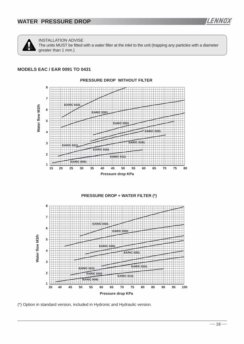
PRESSURE DROP WITHOUT FILTER
MODELS EAC / EAR 0091 TO 0431
PRESSURE DROP + WATER FILTER (*)
WATER PRESSURE DROP
INSTALLATION ADVISEThe units MUST be fitted with a water filter at the inlet to the unit (trapping any particles with a diametergreater than 1 mm.)

Wat
er fl
ow M
3/h
(*) Option in standard version, included in Hydronic and Hydraulic version.
PRESSURE DROP WITHOUT FILTER
Pressure drop KPa
Wat
er fl
ow M
3/h
5
10
15
20
25
25 30 35 40 45 50 55 60
EAC 1003
EAC 1103
EAC 1203
EAC 1303
EAC 0812
EAC 0672
EAC 0552
EAC 0472
PRESSURE DROP + WATER FILTER (*)
Pressure drop KPa
5
10
15
20
25
30 40 50 60 70 80 90
EAC 1003
EAC 1103EAC 1203
EAC 1303
EAC 0812
EAC 0672
EAC 0552
EAC 0472
PRESSURE DROP WITHOUT FILTER
Pressure drop KPa
Wat
er fl
ow M
3/h
5
10
15
20
25
30
25 30 35 40 45 50 55 60 65
EAR 0472
EAR 0552
EAR 0672
EAR 0812EAR 1003
EAR 1103
EAR 1203
EAR 1303
PRESSURE DROP + WATER FILTER (*)
Pressure drop KPa
Wat
er fl
ow M
3/h
5
10
15
20
25
30 40 50 60 70 80 90
EAR 0472
EAR 0552
EAR 0672
EAR 0812
EAR 1003
EAR 1103EAR 1203
EAR 1303
19
MODELS 0472 TO 1303
COOLING ONLY (EAC)
HEAT PUMPS (EAR)
WATER PRESSURE DROP
INSTALLATION ADVISEThe units MUST be fitted with a water filter at the inlet to the unit (trapping any particles with a diametergreater than 1 mm.)

set
mode
on off
• ••
• •
1.195
WATER INLET
WATER OUTLET
660
1.375 POWER SUPPLYCABLE ENTRY
DISPLAYCONTROL
MAIN SWITCH(OPTION)
ELECTRICAL BOX
set
mode
on off
• ••
• •
1.195
WATER INLET
WATER OUTLET
660
1.375 POWER SUPPLYCABLE ENTRY
DISPLAYCONTROL
MAIN SWITCH(OPTION)
ELECTRICAL BOX
1.195
660
COMPRESSOR
ELECTRICAL BOX
WATEREXCHANGER
COIL
1.195
980
COMPRESSOR
WATEREXCHANGER
COIL
ELECTRICAL BOX
set
mode
on off
• ••
• •
WATER INLET
WATER OUTLET
9801.195
1.375
POWER SUPPLYCABLE ENTRY
DISPLAYCONTROL
MAIN SWITCH(OPTION)
ELECTRICAL BOX
set
mode
on off
• ••
• •
DISPLAYCONTROL
MAIN SWITCH(OPTION)
POWER SUPPLYCABLE ENTRY
WATER INLET
WATER OUTLET
ELECTRICALBOX
1.195
1.375
1.960
POWER SUPPLYCABLE ENTRY
WATER EXCHANGER COILS
20
DISPLAYCONTROL
MAIN SWITCH(OPTION)
WATER INLET
WATER OUTLET
ELECTRICALBOX
POWER SUPPLYCABLE ENTRY
1.420
1675
2.250
set
mode
on off
• ••
• •
COMPRESSOR
1.960
1.19
5
ELECTRICAL BOX
AXIAL FAN UNITS DIMENSIONAL DATA
4
3 EAC/EAR 0251S-0291S-0351S-0431S
EAC/EAR 0472S-0552S-0672S-0812S
2 EAC/EAR 0111S-0151S-0191S-0211S
3
4
COMPONENT POSITIONSTANDARD VERSION UNIT
COMPONENT POSITIONSTANDARD VERSION UNIT
COMPONENT POSITIONSTANDARD VERSION UNIT
1 2/
1 EAC/EAR 0091S
5 EAC/EAR 1003S-1103S-1203S-1303S 5 COMPONENT POSITIONSTANDARD VERSION UNIT
COMPRESORSELECTRICAL BOX
WATER EXCHANGER COILS
1420
2250

A ØB
FP1/FP2version 280 800
21
COMPRESSOR
WATER EXCHANGER
COIL
1.195
980
WATER EXCHANGERCOILS
COMPRESSOR
1.195
WATER INLET
WATER OUTLET
660
1.375
POWER SUPPLYCABLE ENTRY
DISPLAYCONTROL
MAIN SWITCH(OPTION)
ELECTRICAL BOX
305547,5
set
mode
on off
• ••
• •
267
316,5
MAIN SWITCH(OPTION)
1.195660
1.375
DISPLAYCONTROL
POWER SUPPLYCABLE ENTRY
ELECTRICAL BOX
WATER INLET
WATER OUTLET
305 233 305267
316,5111,5
set
mode
on off
• ••
• •
MAIN SWITCH(OPTION)
9801.195
1.375
DISPLAYCONTROL
POWER SUPPLYCABLE ENTRY
ELECTRICAL BOX
WATER INLETWATER OUTLET
FP2 version
set
mode
on off
• ••
• •
∅B
A
A ∅B
FP1 version 240 630
425 710
A ∅B
FP1 version 240 630
425 710FP2 version
DISPLAYCONTROL
1.195
1.375
1.960
ELECTRICAL BOX
MAIN SWITCH(OPTION)
POWER SUPPLYCABLE ENTRY
WATER INLET
WATER OUTLET
POWER SUPPLYCABLE ENTRY
A∅B
set
mode
on off
• ••
• •
DISPLAYCONTROL
MAIN SWITCH(OPTION)
ELECTRICAL BOX
WATER INLET
WATER OUTLET
POWER SUPPLYCABLE ENTRY
POWER SUPPLYCABLE ENTRY
1.420
1.67
5
2.250
A
ØB
set
mode
on off
• ••
• •
COMPRESSOR
1.195
660
WATER EXCHANGER
COIL ELECTRICAL BOX
COMPONENT POSITIONSTANDARD VERSION UNIT1 2/
1.960
1.19
5
ELECTRICAL BOX
ELECTRICAL BOX
HIGH STATIC PRESSURE UNITS DIMENSIONAL DATA
4 EAC/EAR 0472S-0552S-0672S-0812S FP1/FP2
1 EAC/EAR0091SFP
2 EAC/EAR 0111S-0151S-0191S-0211S FP
33 EAC/EAR 0251S-0291S-0351S-0431S FP1/FP2 COMPONENT POSITIONSTANDARD VERSION UNIT
COMPONENT POSITIONSTANDARD VERSION UNIT4
5 EAC/EAR 1003S-1103S-1203S-1303S FP1/FP2 COMPONENT POSITIONSTANDARD VERSION UNIT5
COMPRESORSELECTRICAL BOX
WATER EXCHANGER COILS
1420
2250

EAREAC
MODELS EAC / EAR
mm
mm
mm
A - Height
B - Width
C - Depth
0091S 0111S 0151S 0191S 0211S 0251S 0291S 0351S 0431S 0472S 0552S 0672S0812S
Operatingweight kg(*)
1003S 1103S 1203S 1303S
MODELS EAC / EAR
mmA - Height
0091S 0111S 0151S 0191S 0211S 0251S 0291S0351S 0431S 0472S 0552S 0672S0812S
mm
mm
B - Width
C - Depth
EAC
EAR
Operatingweight
1003S1103S 1203S1303S
147
660
1375
1195
150155
1375
1195
660
158168
1375
1195
660
172181
1375
1195
660
185245
1375
1195
660
250272
1375
1195
980
277281
1375
1195
980
285309
980
1375
1195
317345
980
1375
1195
353540
1960
1195
1375
549551
1960
1195
1375
561596
1960
1195
1375
612670
1960
1195
1375
685803825
948971
10591084
11041129
1375 1375 1375 1375 1375 1615 1615 1615 1615 1615
- - - - - 1800 1800 1800 1800 1800
660
1195 1195
660
1195
660
1195
660
1195
660
1195
980
1195
980 980
1195
980
1195 1960
1195
1960
1195
1960
1195
1960
1195
156 173 186 199 263 297 296 324 360 590 581 626 700- - - - - 317 316 344 380 630 621 666 740
159 176 190 204 268 302 301 332 368 599 592 642 716- - - - - 322 321 352 388 639 632 682 756
1615
1800
1615
1800
1615
1800
843 988 1099 1144843 988 1099 1144
865 1011 1124 1169865 1011 1124 1169
2250
1420
1955
19552250
1420
1955
19552250
1420
1955
19552250
1420
1955
1955
(*) Not included Hydronic or Hydraulic version (see page 29).
(*) Not included Hydronic or Hydraulic version (see page 29).
set
mode
on off
• ••
• •
1 meter (*)1 meter (*)
3 meters (*)
1 meter (*)
1 meter (*)
1 meter (*)
1 meter (*)
3 meters (*)
set
mode
on off
• ••
• •
1 meter (*)
1 meter (*)
1 meter (*)
1 meter (*)
3 meters (*)
1 meter (*)
1 meter (*)
set
mode
on off
• ••
• •
B
A
C
2250
1420
1675
2250
1420
1675
2250
1420
1675
2250
1420
1675
kg(*)
(*) Keep this space free around the unit for installation, for all unit versions
22
1,5 meters (*)
1,5 meters (*)
5 meters ( *)
set
mode
on off
• ••
• •
1,5 meters (*)
1,5 meters (*)
DIMENSIONAL DATA AND WEIGHTS
HIGH STATIC PRESSURE UNITS
STANDARD AXIAL FAN UNITS
EAC/EAR 0091S-0111S-0151S-0191S-0211S
EAC/EAR 0472S-0552S-0672S-0812S
SERVICE AREASEAC/EAR 0251S-0291S-0351S-0431S
EAC/EAR 1003S-1103S-1203S-1303S
FP2FP/FP1
FP2
FP/FP1
FP2
FP/FP1

(1) The above data shows noise levels without isolation for compressor(2) The above data shows noise levels with isolation for compressor (option)
(1)(2)(1)(2)(1)(2)(1)(2)(1)(2)(1)(2)(1)(2)(1)(2)(1)(2)(1)(2)(1)(2)(1)(2)(1)(2)
(1)(2)(1)(2)
LowspeedHigh
speed(1)(2)(1)(2)
LowspeedHigh
speed(1)(2)(1)(2)
LowspeedHigh
speed(1)(2)(1)(2)
LowspeedHigh
speed
0091SMODELS EAC / EAR 0111S/0211SNoise level attenuation,
because of fan speed regulation
0251S/0431S 0472S/0812S
STANDARD AXIAL FAN UNITS
0091S
8000 Hz
EACEAR 4000 Hz2000 Hz1000 Hz500 Hz250 Hz125 Hz
Global sound power
Lw dB(A)
Spectrum per octave band (dBA) Soundpressure
at 10m. (dBA)
0111S
0151S
0191S
0211S
0251S
0291S
0351S
0431S
0472S
0552S
0672S
0812S
1003S
1103S
1203S
1303S
-1 dBA -2 dBA -3 dBA -3 dBA
64,6 67,6 67,8 67,6 67,2 63,5 59,0
67,6 70,6 70,8 70,4 68,5 64,2 57,5
67,6 70,7 71,4 71,1 68,7 66,4 60,5
67,6 70,6 71,4 71,8 69,2 67,2 59,9
71,1 74,9 73,2 72,5 69,6 57,067,6
70,0 74,8 72,7 73,5 70,4 57,573,8
72,4 76,7 75,9 75,4 70,2 62,380,3
72,6 76,1 75,8 77,6 74,2 67,380,3
73,5 77,1 76,3 77,2 71,4 65,080,3
73,0 77,8 75,7 76,5 73,4 60,576,8
75,4 79,7 78,9 78,4 73,2 65,383,3
75,6 79,1 78,8 80,6 77,2 70,383,3
76,5 80,1 79,3 80,2 74,4 68,083,375,9 78,4 78,1 78,1 71,9 66,183,3
75,4 77,8 77,9 78,4 74,2 67,883,3
75,3 78,2 77,9 76,9 71,0 64,383,3
72,8 75,7 73,2 73,3 70,3 59,376,8
71,4 79,6 78,0 74,1 65,570,670,0 76,7 75,8 75,2 70,7 62,470,6
78,7
64,6 67,6 67,7 66,8 65,9 61,9 56,7
67,6 70,6 70,8 69,7 67,9 63,3 56,2
67,6 70,6 71,1 70,2 68,0 64,8 58,5
67,6 70,6 71,1 70,6 68,3 65,4 58,0
70,9 73,2 71,3 70,3 66,9 55,767,6
69,8 72,7 70,2 70,3 67,3 56,373,8
72,3 75,2 74,9 73,9 68,0 61,380,3
72,4 74,8 74,9 75,4 71,2 64,880,3
72,9 75,4 75,1 75,1 68,9 63,180,3
75,0 80,6 80,5 74,4 66,076,374,4 78,5 79,4 76,3 71,3 63,476,3
79,2
73,0 78,5 78,4 76,1 68,973,472,0 76,2 76,9 76,4 72,7 65,873,3
79,7
78,9 80,8 82,8 76,8 70,081,978,7 79,6 82,3 79,4 74,2 67,781,9
81,4
71,9 76,6 79,3 75,8 68,573,471,6 75,1 78,8 77,9 73,4 66,273,3
79,6
78,6 79,8 83,1 76,6 69,681,978,6 79,1 82,9 80,2 74,7 68,081,9
81,3
73,5 78,0 80,4 76,3 68,475,073,3 76,9 80,0 79,4 74,3 66,175,0
80,6
80,8 81,4 84,8 77,5 70,384,280,7 80,9 84,6 82,2 76,0 69,084,2
82,9
Global sound power level measured in compliance with ISO standard 3744 and under Eurovent certification program
Sound pressure in dB(A) calculated at 10 m, in a free field on a reflecting surface, is given as a guide only and with a directibilityof +/- 3 dBA.
Only the sound power spectrum and the global sound power value are used in determining pressure characteristics on site.The data table above, are calculated:A) For units: EAC/EAR 0091S to 0812S Operating on cooling or heating mode (with ambient temperatures higher than +35ºC), and at maximum fan speed. For ambient temperatures lower than +35 ºC and unit working on cooling mode, the fan, speed regulating, and produce an attenuation of noise level as follow: Sound pressure level attenuation calculated at 10 m (dBA) shows in the table below, (minimum speed when ambient temperatures lower than +20 ºC).
B) For units: EAC/EAR 1003S to 1303S. - For ambient temperatures lower than +35ºC and unit working on cooling mode the fan is running in low speed, and with ambient temperatures higher than +35ºC the fan is running in high speed. - For ambient temperatures higher than +6ºC and unit working on heating mode the fan is running in low speed and with ambient temperatures lower than +6ºC the fan is running in high speed.
23
73 45
75 47
76 48
76 48
79 51
79 51
81 53
83 55
82 54
82 54
84 56
86 58
85 5783 55
84 56
83 55
79 51
84 5681 53
72 44
75 47
75 47
75 47
77 49
76 48
80 52
81 53
80 52
85 5783 5585 5782 5487 5986 5885 5783 5587 5986 5886 5884 5689 6188 60
NOISE LEVELS
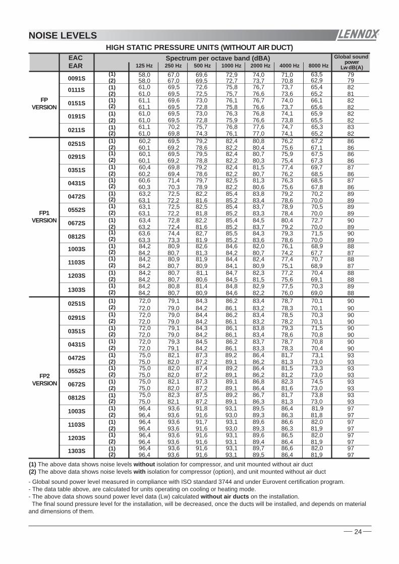
60,1
60,4
60,660,2
60,1
60,3
(1) The above data shows noise levels without isolation for compressor, and unit mounted without air duct(2) The above data shows noise levels with isolation for compressor (option), and unit mounted without air duct
0091S
EACEAR
Global sound power
Lw dB(A)
Spectrum per octave band (dBA)
0111S
0151S
0191S
0211S
0251S
0291S
0351S
0431S
0472S
0552S
0672S
0812S
0251S
0291S
0351S
0431S
0472S
0552S
0672S
0812S
1003S
1103S
1203S
1303S
1003S
1103S
1203S
1303S
8000 Hz4000 Hz2000 Hz1000 Hz500 Hz250 Hz125 Hz
74,3
(2)(1)
(2)(1)
(2)(1)
(2)(1)
(2)(1)
(2)(1)
(2)(1)
(2)(1)
(2)(1)
(2)(1)
(2)(1)
(2)(1)
(2)(1)
(2)(1)
(2)(1)
(2)(1)
(2)(1)
(2)(1)
(2)(1)
(2)(1)
(2)(1)
67,0 69,6 72,9 74,0 71,0 63,558,0
69,5 72,6 75,8 76,7 73,7 65,461,0
69,6 73,0 76,1 76,7 74,0 66,161,1
69,5 73,0 76,3 76,8 74,1 65,961,0
70,2 75,7 76,8 77,6 74,7 65,361,1
69,5 79,2 82,4 80,8 76,2 67,260,2
69,5 79,5 82,4 80,7 75,9 67,5
69,8 79,2 82,4 81,5 77,4 69,7
71,4 79,7 82,5 81,3 76,3 68,5
72,5 82,2 85,4 83,8 79,2 70,263,2
72,5 82,5 85,4 83,7 78,9 70,563,1
72,8 82,2 85,4 84,5 80,4 72,763,4
74,4 82,7 85,5 84,3 79,3 71,563,6
79,1 84,3 86,2 83,4 78,7 70,172,0
79,0 84,4 86,2 83,4 78,5 70,372,0
79,1 84,3 86,1 83,8 79,3 71,572,0
79,3 84,5 86,2 83,7 78,7 70,872,0
82,1 87,3 89,2 86,4 81,7 73,175,0
82,0 87,4 89,2 86,4 81,5 73,375,0
82,1 87,3 89,1 86,8 82,3 74,575,0
82,3 87,5 89,2 86,7 81,7 73,875,0
69,4 78,6 82,2 80,7 76,2 68,5
69,8 76,1 77,0 74,1 65,261,0
69,2 78,6 82,2 80,4 75,6 67,160,1
69,2 78,8 82,2 80,3 75,4 67,3
67,0 69,5 72,7 73,7 70,8 62,958,0
69,5 72,5 75,7 76,6 73,6 65,261,0
69,5 72,8 75,8 76,6 73,7 65,661,1
69,5 72,8 75,9 76,6 73,8 65,561,0
70,3 78,9 82,2 80,6 75,6 67,8
72,2 81,6 85,2 83,4 78,6 70,063,1
72,2 81,8 85,2 83,3 78,4 70,063,1
72,4 81,6 85,2 83,7 79,2 70,063,2
73,3 81,9 85,2 83,6 78,6 70,063,3
79,0 84,2 86,1 83,2 78,3 70,172,0
79,0 84,2 86,1 83,2 78,2 70,172,0
79,0 84,2 86,1 83,4 78,6 70,872,0
79,1 84,2 86,1 83,3 78,3 70,472,0
82,0 87,2 89,1 86,2 81,3 73,075,0
82,0 87,2 89,1 86,2 81,2 73,075,0
82,0 87,2 89,1 86,4 81,6 73,075,0
82,1 87,2 89,1 86,3 81,3 73,075,0
(2)(1)
(2)(1)
(2)(1)
(2)(1)
80,9 82,6 84,6 82,0 76,1 68,984,2
80,9 81,9 84,4 82,4 77,4 70,784,2
80,7 81,1 84,7 82,3 77,2 70,484,2
80,8 81,4 84,8 82,9 77,5 70,384,2
80,7 81,3 84,2 80,7 74,2 67,784,2
80,7 80,9 84,1 80,9 75,1 68,984,2
80,7 80,6 84,5 81,5 75,6 69,184,2
80,7 80,9 84,6 82,2 76,0 69,084,2
(2)(1)
(2)(1)
(2)(1)
(2)(1)
93,6 91,8 93,1 89,5 86,4 81,996,4
93,6 91,7 93,1 89,6 86,6 82,096,4
93,6 91,6 93,1 89,6 86,5 82,096,4
93,6 91,6 93,1 89,7 86,6 82,096,4
93,6 91,6 93,0 89,3 86,3 81,896,4
93,6 91,6 93,0 89,3 86,3 81,996,4
93,6 91,6 93,1 89,4 86,4 81,996,4
93,6 91,6 93,1 89,5 86,4 81,996,4
- Global sound power level measured in compliance with ISO standard 3744 and under Eurovent certification program.- The data table above, are calculated for units operating on cooling or heating mode.- The above data shows sound power level data (Lw) calculated without air ducts on the installation. The final sound pressure level for the installation, will be decreased, once the ducts will be installed, and depends on materialand dimensions of them.
24
79
82
82
82
83
86
86
87
87
89
89
90
90
90
90
90
90
93
93
93
93
86
82
86
86
79
81
82
82
86
89
89
89
89
90
90
90
90
93
93
93
93
88
88
88
89
87
87
88
88
97
97
97
97
97
97
97
97
HIGH STATIC PRESSURE UNITS (WITHOUT AIR DUCT)
FPVERSION
FP1VERSION
FP2VERSION
NOISE LEVELS

COOLING MODE
HEATING MODE
HEATING MODE
COOLING MODE
MODELSHot water outlettemperature (operation)Hot water inlettemperature (start)
EAR
Difference hot waterinlet/outlet
Air inlet temperature
0091 TO 0812S 1003 TO 1303S
MODELS
Inlet chilledwater temperature
Outlet chilledwater temperature
EAC / EAR
Air inlet temperature
0091 TO 0431S 1003 TO 1303S0472 TO 0812S
Minimum : +20°C
Minimum : +10 °C
Maximum : +8°CMinimum :+3°CMaximum : +43°C
Maximum : +50°C
Maximum : +23°CMinimum : -10°C (2)
Minimum : +20ºC
Minimum : +10ºC
Maximum : +8ºCMinimum : +3ºCMaximum : +43ºC
Maximum : +50ºC
Maximum : +23ºCMinimum : -10ºC (2)
Minimum : +5°C
Minimum : +10 °C
Maximum : +46°CMinimum : 0°C (1)Maximum : +17°C
Maximum : +12°CMinimum : +5ºC
Minimum : +8ºC
Maximum : +46°CMinimum : 0°C (1)Maximum : +17ºC
Maximum : +12ºCMinimum : +5°C
Minimum : +9 °C
Maximum : +46°CMinimum : 0°C (1)Maximum : +17°C
Maximum : +12°C
OUTSIDE THESE VALUES, PLEASE CONSULT US(2) With the option heating low ambient kit (-15ºC), it is possible the unit operation down to -15ºC
NOTE: With outdoor temperatures below +5°C, add glycol(1) With the option cooling low ambient kit ( -15ºC), it is possible the unit operation down to -15ºC in EAC units.
NOTE: With outdoor temperatures below +5°C, add glycol.
25
A
0091S to0812S
1003S to1303S
+9ºC +7ºC
A
0091S to0812S
1003S to1303S
+9ºC +7ºC
-10º +12º
+44º
0º
A
+46ººC
Water outlet temperature
Air
inle
t te
mpe
ratu
re
ºC+5º-15º
+40º
-7º
OPTION STD
-10º +12º
+44º
0º
A
+46ººC
Water outlet temperature
Air
inle
t te
mpe
ratu
re
ºC+5º-15º
+40º
-7º
OPTION STD-1º
-10º
23º
20° 50°42°
ºC
Water outlet temperatureºC
-15º
STD
OPTION
Air
inle
t te
mpe
ratu
re
HEATING MODE
COOLING ONLY UNITS (EAC)
HEAT PUMP UNITS (EAR)
COOLING MODE
OPERATION LIMITS
STANDARD AXIAL FAN UNITS WITH AIR DUCTS
Available static pressure PaMaximum ambient temperature ºC
30 500091 to 0211S
4043
AVAILABLE PRESSURE UP TO 50 Pa
(1) With the option heating low ambient kit (-15ºC), it is possible the unit operation down to -15ºC
30 500251 to 1303S
3842
Available static pressure PaMinimum ambient temperature ºC (1)
30 500091 to 0211S
-6-8
AVAILABLE PRESSURE UP TO 50 Pa30 50
0251 to 1303S
-6-8
STANDARD AXIAL FAN UNITS WITHOUT AIR DUCTS

COOLING MODE
HIGH STATIC PRESSURE UNITS
UNITS WITH LOW WATER TEMPERATURE KIT (OPTION)
1
2
3
4
5
6
7
8
9ºC
-10 -8 -6 -4 -2 0 2 4 6 8 10Water outlet temperature ºC
DIFFERENCE OF TEMPERATURE (water inlet/water outlet)
Maximum difference of temperature
Minimum difference of temperature
Nominal difference of temperature
150 250 300200 350 150 250 300200 350-6 -5-10-10 -8
AVAILABLE PRESSURE UP TO 250 OR350 Pa FP2 VERSION 0251 to 0812S-FP2 MODEL UNITS
Available static pressure PaMinimum ambient temperature ºC (2)
1003 to 1303S-FP2 MODEL UNITS
50 100 12575-5-8-10 -6
AVAILABLE PRESSURE UP TO 120 PaFP1 VERSION 0251 to 1303S-FP1 MODEL UNITS
Available static pressure PaMinimum ambient temperature ºC (2)
Available static pressure PaMinimum ambient temperature ºC (2)
AVAILABLE PRESSURE UP TO 200 PaFP VERSION 0091 to 0211S-FP MODEL UNITS
50 150 200100-8 -6-10-10
150 250 300200 350 150 250 300200 35038 354447 41
AVAILABLE PRESSURE UP TO 250 OR350 Pa FP2 VERSION 0251 to 0812S-FP2 MODEL UNITS
Available static pressure PaMaximum ambient temperature ºCMinimum ambient temperature ºC 0ºC
1003 to 1303S-FP2 MODEL UNITS
50 100 12575354346 39
AVAILABLE PRESSURE UP TO 120 PaFP1 VERSION 0251 to 1003S-FP1 MODEL UNITS
Available static pressure PaMaximum ambient temperature ºCMinimum ambient temperature ºC 0ºC (1) 0ºC (1)
1103 to 1303S-FP1 MODEL UNITS
26
OPERATION LIMITS
50 100 125753544 3741
N/A N/A4447 41
N/A N/A-10-10 -8
0ºC (1)
HEATING MODE
(2) With the option heating low ambient kit (-15ºC), it is possible the unit operation down to -15ºC.
Available static pressure PaMaximum ambient temperature ºC
AVAILABLE PRESSURE UP TO 200 PaFP VERSION 0091 to 0211S-FP MODEL UNITS
Minimum ambient temperature ºC 0ºC (1)
50 150 20010041 384546
(1) With the option cooling low ambient kit (-15ºC), it is possible the unit operation down to -15ºC.

27
For location inside, keep in mind following advice:
-In heat pump units during defrost cycle, the units produce a great amount of water melting the ice off coils.If you wish to drain the water, an auxiliary drip tray, should to be installed below the unit to collect and carry out waterwhere desired.
-Air duct installation:If air duct has been installed, the operating limits get reduced (see operation limits section in this manual).
Air outlet
Air inlet Unit
Auxiliary drip tray(heat pump unit)
Air outlet duct (2)
Air inlet duct (1)
LOCATION INSIDE
(1) The air intake plenum (option) available for models from 0251 to 1303 makes easier the installation of the airintake duct (see page 6).(2) The discharge plenum (option) lets the installation of a square discharge duct for the high static pressure unitsFP1 and FP2 (see page 6).
UNIT INSTALLATION INSIDE
Introduction and description of the components............................................29
Technical data.......................................................................................................29
Single pump .........................................................................................................29
Operation principles .............................................................................................30
Available static pressure water pump...................................................................31
Glycol solution unit.................................................................................................31
Water flow volume.............................................................................................32
Water tank heater (an option).................................................................................32
Hydraulic version unit equipment and dimensional data .................................33
Hydronic version unit equipment and dimensional data ............................. 35
HYDRAULIC EQUIPMENT
CONTENTS

Power
MODELS
Maxi current
kWA
0091S 0111S 0151S 0191S 0211S 0251S 0291S
0472S 0552S 0672S 0812S
Power
MODELS
Maxi current
kWA
MODELS 0091S 0111S 0151S 0191S 0211S 0251S 0291S
0472S 0552S 0672S 0812SMODELS
CapacityMax. pressure
Pressure available (nominal water flow)Water flow rate nominal
Net weight(add to the unit weight)
CapacityMax. pressure
Pressure available (nominal water flow)Water flow rate nominalNet weight(add to the unit weight)
(1) Only for units with Hydronic version
Expansion vessel
Water tank (1)
Hydraulic connections
Expansion vessel
Water tank (1)
Hydraulic connections
l
KPa
bar
l/s.
Kg
l
l
KPa
bar
l/s.
Kg
l
PumpType
Voltage
PumpType
Voltage
V.
V.
Kg
Kg
Hydraulic version
Hydronic version
Hydraulic version
Hydronic version
inches
inches
0351S 0431S
0351S 0431S
1203S
1203S 1303S1003S 1103S
1303S1003S 1103S
Horizontal multistage centrifugal pump
Horizontal multistage centrifugal pump
196 161 152 140 126 131 106
5 5 5 5 5 12 12
0,42 0,53 0,64 0,83 0,91 1,10 1,29
14 14 14 14 15 16 16
1"G 1"G 1"G 1"G 1"G 1 1/2"G 1 1/2"G
50 50 50 50 50 75 75
4
122 111 164 107
18 18 18 18
2,10 2,46 2,99 3,61
55 55 57 57
2"G 2"G 2"G 2"G
100 100 100 100
4
0,49 0,49 0,49 0,72 0,72 0,72 0,72
1,17 1,17 1,55 1,55
2,3 2,3 2,3 2,4-1,4 2,4-1,4 2,4-1,4 2,4-1,4
3,0-1,7 3,0-1,7 4,8-2,8 4,8-2,8
1N~230V
3~230V-3~400V
44 44 44 44 45 47 47
23 23 24 24
3~230V-3~400V
140 96
12 12
1,53 1,84
17 17
1 1/2"G 1 1/2"G
75 75
1,10 1,10
3,0-1,7 3,0-1,7
48 48
35
81
2 1/2"G
240
2,5
4,2
26
35
81
2 1/2"G
240
26
35
81
2 1/2"G
240
26
35
81
2 1/2"G
240
26
2,7
4,5
2,2
3,7
2,3
3,9
3~400V
189 172 151 131
4,30 4,83 5,47 6,07
DESCRIPTION- All hydraulic accessories are integrated in the standard unit casing
COMPONENTS:HYDRONIC VERSION:•Water tank•Water pump•Expansion vessel•Collapsible water filter•Safety valve•Manometer•Flow switch
HYDRAULIC VERSION:
•Water pump•Expansion vessel•Collapsible water filter•Safety valve•Manometer•Flow switch
29
INTRODUCTION - DESCRIPTION OF THE COMPONENTS
SINGLE PUMP
TECHNICAL DATA

The EcoLeanTM system comprises a water cooler or air/water pump combined with a series of hydraulic accessoriesobtaining the Hydraulic or Hydronic version.
COMPONENTS:
HYDRONIC VERSION:1,2,3,4,5,6,7,8,9,10, 11
HYDRAULIC VERSION:1,4,5,6,7,8,9,10,11
7.- Water pump 8.- Air purge valve 9.- Plate exchanger10.- Flow switch11.- Drain valve12.- Water isolation valves ( in option)
1.- Detachable water filter 2.- Water tank 3.- Water tank heater (in option) 4.- Safety valve 5.- Manometer 6.- Expansion vessel
30
Inside terminal unit
Hydraulic connections
7 65
4
211
1
10
11
89
3
8
12
12
Customerconnection
Inside terminal unit
Hydraulic connections
7
6
5
4
11
1
10
9 8 12
12
Customerconnection
Inside terminal unit
Hydraulic connections
10
11
89
12
1211
Customerconnection
7
12
8
1
5
46
2
3
OPERATING PRINCIPLES
Models 0091 to 0812
Models 0091 to 1303HYDRAULIC VERSION
HYDRONIC VERSION
Models 1003 to 1303

COOL HEATETHYLENEGLYCOL %
PRESSUREDROP
CAPACITIESMINIMUM AMBIENT TEMPERATUREOR WATER OUTLET TEMPERATURE
WATERFLOW
FROM +5ºC TO 0ºCFROM 0ºC TO -5ºC
FROM -5ºC TO -10ºC
FROM -10ºC TO -15ºC
10 %20 %30 %
1,051,101,15
1,021,051,08
0,990,980,97
0,9940,9930,99
35 % 1,18 1,10 0,96 0,987
Unit conversion:Pressure 1KPa = 1/9,8 m.c.a. = 0,01 bar
1 bar = 10 m.c.a. = 100 kPa
Example: 10 % glycol in EAC0091SKHNMinimum flow: 1,19 m3/h x 1.02Pressure drop x 1.07System capacity x 0.99
The amount of anti-freeze required will vary depending on the minimum ambient temperature or the water outlettemperature. When the percentage of glycol increases the standard pump flow decreases, the pressure dropincreases and the cooling and thermal capacities drop. As a result the minimum flow must be multiplied by thecoefficient shown in the table:
NOTE: The flow data indicated in table are between a minimum and a maximum water flow.With the twin pumps kit, the available static pressure will decrease 5% from the data shown above.
If the outside temperature where the system is to be installed or the water outlet temperature is likelyto drop below 5ºC, it is very important to use glycol anti-freeze.
MODEL
m3/hkPa
l/s
MODEL
m3/h
kPa
l/s
MODEL
m3/h
kPa
l/s
MODEL
m3/h
kPa
l/s
MODEL
m3/h
kPa
l/s
MODEL
m3/h
kPa
l/s
Water flow
Available static pressure
Water flow
Available static pressure
Water flow
Available static pressure
Water flow
Available static pressure
Water flow
Available static pressure
Water flow
Available static pressure
MODEL
m3/h
kPa
l/sWater flow
Available static pressure
1,21
216
1,53
196
1,83
186
1,36
207
1,72
178
2,06
170
1,51
196
EAC / EAR 0091S
1,91
161
EAC / EAR 0111S
2,29
152
EAC / EAR 0151S
EAC / EAR 0291S
1,68
183
2,12
144
2,54
132
1,89
163
2,39
126
2,86
104
EAC / EAR 0351S EAC / EAR 0431S
EAR 0472S EAR 0552S EAR 0672S
EAR 0812S EAC 0472S EAC 0552S
EAC 0672S EAC 0812S
0,34 0,42 0,510,38 0,48 0,570,42 0,53 0,640,47 0,59 0,710,53 0,66 0,79
3,72
153
4,40
210
5,30
161
4,18
129
4,95
176
5,96
132
4,64
106
5,50
140
6,62
96
5,16
83
6,12
98
7,36
47
5,81
55
6,88
43
1,03 1,22 1,471,16 1,38 1,661,29 1,53 1,841,43 1,70 2,041,61 1,91
6,05
156
7,07
140
8,60
226
6,81
139
7,96
126
9,68
195
7,57
122
8,84
111
10,75
164
8,41
104
9,82
93
11,94
131
9,46
82
11,05
69
13,44
90
1,68 1,96 2,391,89 2,21 2,692,10 2,46 2,992,34 2,73 3,322,63 3,07 3,73
10,39
188 156 140
11,69
153 141 128
12,99
111 128 115
14,43
56 115 99101 78
2,89 3,25 3,61 4,01
223 180194 147165 107134 5497
2,38
170
2,63
167
3,16
175
2,68
154
2,96
144
3,56
152
2,98
140
EAC / EAR 0191S
3,29
126
EAC / EAR 0211S
3,96
131
EAC / EAR 0251S
3,31
124
3,65
111
4,40
110
3,72
107
4,11
100
4,95
87
0,66 0,73 0,880,74 0,82 0,990,83 0,91 1,100,92 1,01 1,221,03 1,14 1,37
6,05 6,81 7,57 8,41 9,46
1,68 1,89 2,10 2,34 2,63
7,07 7,96 8,84 9,82 11,05
1,96 2,21 2,46 2,73 3,07
8,60 9,68 10,75 11,94 13,44
2,39 2,69 2,99 3,32 3,73
10,39 11,69 12,99 14,43
2,89 3,25 3,61 4,01
EAC / EAR 1003S
EAC / EAR 1103S EAC / EAR 1203S EAC / EAR 1303S
12,38 13,93 15,48 17,20 19,35
3,44 3,87 4,30 4,78 5,38
215 206 196 183 164
15,76 17,72 19,69 21,88 24,62
4,38 4,92 5,47 6,08 6,84
206 194195 178181 160164 138139 105
13,90 15,63 17,37 19,30 21,72
3,86 4,34 4,83 5,36 6,03
17,48 19,66 21,84 24,27 27,31
4,85 5,46 6,07 6,74 7,58
180 161 138 109 75
31
AVAILABLE STATIC PRESSURE OF THE UNIT
GLYCOL SOLUTION UNIT
WATER FLOW AND AVAILABLE STATIC PRESSURE ( Factory supplied; standard water pump and filter).

Models
Voltage v
0472/08120251/0431
Tank anti-freeze heaterWater tank electrical heater*
0091/0211
kW
1003/1303
kW
3~230V - 3~400V2,252,25129
1N~230V
2,256
624
3~400V
The option for Antifreeze protection on the buffer tank includes on cooling only units a immersion heater with safetythermostat.On heat pump units only when fitted with a buffer tank it is possible to have anti freeze plus supplemental water heaterthis includes immersion heater with safety thermostat and a adjustable heater thermostat.
Tank anti-freeze heater: It starts when water temperature in the buffer tank is lower than + 5 ºC (Not for units withlow water temperature kit).Water tank electrical heater: heat pump units only. The heater works as anti-freeze heater as explained before andas supplementary heater, when inlet warm water reaches a temperature below a value selected (example: 30 ºC)through an independent thermostat included.
Power consumption is:
If the water volume in the system is greater than that detailed in the table it will be necessary to add additionalexpansion vessel(s).
MINIMUM WATER FLOWThe installation must never operate with less than the minimum water flow (see table above), this will cause:
i. - Freezing the water heat exchanger.ii. - Contamination of the heat exchanger.
MAXIMUM WATER FLOWSee maximum water flow, (see table above). Always assure the minimum ∆T to the exchanger of 3ºC.
MAXIMUM WATER VOLUME IN THE INSTALLATIONThe units with Hydronic or Hydraulic module include a expansion vessel.The table below details the maximum water volume in the system.
The system design must allow for water expansion and contraction.
Water volume in liters
Water + 10% gytWater + 20% gytWater + 30% gyt
0091/0211 0251/0431 0472/0812SolutionModels
Water
Water + 35% gyt
1003/1303
225 550175 400150 350
850650575
300 450125
165012601115875
225 325110 650
32
(*) Heat pump units only
WATER FLOW VOLUME
WATER TANK HEATER (AN OPTION)

FLOW SWITCH
WATER FILTER
WATER PUMP
EXPANSIONVESSEL
WATER FILTER
WATER PUMP
EXPANSIONVESSEL
FLOW SWITCH
FLOW SWITCHWATER FILTER
WATER PUMP
EXPANSIONVESSEL
COMPRESSOR
ELECTRICAL BOX
COMPRESSOR
COMPRESSORS
1.195
980
WATEREXCHANGER
COIL
WATER EXCHANGER COILS
1.195
660
WATEREXCHANGER
COIL
set
mode
on off
• ••
• •
set
mode
on off
• ••
• •
set
mode
on off
• ••
• •
set
mode
on off
• ••
• •
33
DISPLAYCONTROL
MAIN SWITCH(OPTION)
WATER INLET
WATER OUTLET
ELECTRICALBOX
POWER SUPPLYCABLE ENTRY
1.420
1675
2.250
set
mode
on off
• ••
• •
1.960
1.19
5
ELECTRICAL BOX
1.195
WATER INLET
WATER OUTLET
660
1.375 POWER SUPPLYCABLE ENTRY
WATER INLET
WATER OUTLET
9801.195
1.375POWER SUPPLYCABLE ENTRY
DISPLAYCONTROL
MAIN SWITCH(OPTION)
POWER SUPPLYCABLE ENTRY
WATER INLETWATER OUTLET
ELECTRICALBOX
1.195
1.375
1.960
POWER SUPPLYCABLE ENTRY
1.195
WATER INLET
WATER OUTLET
660
1.375 POWER SUPPLYCABLE ENTRY
DISPLAYCONTROL
DISPLAYCONTROL
DISPLAYCONTROL
MAIN SWITCH(OPTION)
MAIN SWITCH(OPTION)
MAIN SWITCH(OPTION)
ELECTRICAL BOX
ELECTRICAL BOX
ELECTRICAL BOX
ELECTRICAL BOX
AXIAL FAN UNITS EQUIPMENT AND DIMENSIONAL DATA
1 EAC/EAR 0091S
4
3 EAC/EAR 0251S-0291S-0351S-0431S
EAC/EAR 0472S-0552S-0672S-0812S
2 EAC/EAR 0111S-0151S-0191S-0211S
3
4
COMPONENT POSITIONHYDRAULIC VERSION UNIT
COMPONENT POSITIONHYDRAULIC VERSION UNIT
COMPONENT POSITIONHYDRAULIC VERSION UNIT
1 2/
(HYDRAULIC VERSION)
EAC/EAR 1003S-1103S-1203S-1303S5 5 COMPONENT POSITIONHYDRAULIC VERSION UNIT
WATERPUMP
FLOW SWITCH COMPRESORSELECTRICAL BOX
WATER EXCHANGER COILS
WATERFILTER
EXPANSIONVESSEL
1420
2250

A ∅B
FP1 Version 240 630
425 710FP2 Version
A ∅B
FP1 Version 240 630
425 710FP2 Version
A ØB
FP1/FP2version 280 800
34
FLOW SWITCH
WATER FILTER
WATER PUMP
EXPANSIONVESSEL
WATER FILTER
WATER PUMP
EXPANSION VESSEL
FLOW SWITCH
FLOW SWITCHWATER FILTER
WATER PUMP
EXPANSIONVESSEL
COMPRESSOR
ELECTRICAL BOX
COMPRESSOR
COMPRESSORS
1.195
980
WATEREXCHANGER
COIL
WATER EXCHANGER COILS
1.195
660
WATEREXCHANGER
COIL
DISPLAYCONTROL
MAIN SWITCH(OPTION)
ELECTRICAL BOX
WATER INLET
WATER OUTLET
POWER SUPPLYCABLE ENTRY
POWER SUPPLYCABLE ENTRY
1.420
1.67
5
2.250
A
ØB
set
mode
on off
• ••
• •
1.960
1.19
5
ELECTRICAL BOX
1.195660
1.375
DISPLAYCONTROL
DISPLAYCONTROL
1.195
1.375
1.960
1.195660
1.375
DISPLAYCONTROL
MAIN SWITCH(OPTION)
9801.195
1.375
DISPLAYCONTROL
WATER INLETWATER OUTLET
POWER SUPPLYCABLE ENTRY
ELECTRICAL BOX
MAIN SWITCH(OPTION)
WATER INLET
WATER OUTLET
ELECTRICAL BOX
WATER INLETWATER OUTLET
MAIN SWITCH(OPTION)
ELECTRICAL BOX
ELECTRICAL BOX
MAIN SWITCH(OPTION)
WATER INLET
WATEROUTLET
POWER SUPPLYCABLE ENTRY
POWER SUPPLYCABLE ENTRY
POWER SUPPLYCABLE ENTRY
POWER SUPPLYCABLE ENTRY
ELECTRICAL BOX
HIGH STATIC PRESSURE UNITS EQUIPMENT AND DIMENSIONAL DATA
(HYDRAULIC VERSION)
2 EAC/EAR 0111S-0151S-0191S-0211S FP
305 233 305267
316,5111,5
4 EAC/EAR 0472S-0552S-0672S-0812S FP1/FP2
1 EAC/EAR0091SFP
3 EAC/EAR 0251S-0291S-0351S-0431S FP1/FP2 3
4
COMPONENT POSITIONHYDRAULIC VERSION UNIT
COMPONENT POSITIONHYDRAULIC VERSION UNIT
COMPONENT POSITIONHYDRAULIC VERSION UNIT
1 2/
5 EAC/EAR 1003S-1103S-1203S-1303S FP1/FP2 5 COMPONENT POSITIONHYDRAULIC VERSION UNIT
WATERPUMP
FLOW SWITCH COMPRESORSELECTRICAL BOX
WATER EXCHANGER COILS
WATERFILTER
EXPANSIONVESSEL
1420
2250
set
mode
on off
• ••
• •
A∅B
305547,5
set
mode
on off
• ••
• •
267
316,5
set
mode
on off
• ••
• •
∅B
A
mode
• ••
• •

FLOW SWITCH
WATER FILTER
WATER PUMP
EXPANSIONVESSEL
WATER TANK
WATER FILTER
WATER PUMP
EXPANSION VESSEL
WATER TANK
FLOW SWITCH
COMPRESSOR
COMPRESSORS
1.195
980
WATEREXCHANGER
COIL
ELECTRICAL BOX
WATEREXCHANGERCOILS
ELECTRICAL BOX
35
FLOW SWITCHWATER FILTER
WATER PUMP
EXPANSION VESSEL
WATER TANK
COMPRESSOR
ELECTRICAL BOX
1.195
660
WATEREXCHANGER
COIL
1.960
1.19
5
AXIAL FAN UNITS EQUIPMENT AND DIMENSIONAL DATA
3
4
COMPONENT POSITIONHYDRONIC VERSION UNIT
COMPONENT POSITIONHYDRONIC VERSION UNIT
(HYDRONIC VERSION)
COMPONENT POSITIONHYDRONIC VERSION UNIT1 2/
5 COMPONENT POSITIONHYDRONIC VERSION UNIT
WATERPUMP
WATER TANK
FLOW SWITCH COMPRESORSELECTRICAL BOX
WATER EXCHANGER COILS
WATERFILTER
EXPANSIONVESSEL
1420
2250
set
mode
on off
• ••
• •
set
mode
on off
• ••
• •
set
mode
on off
• ••
• •
set
mode
on off
• ••
• •
DISPLAYCONTROL
MAIN SWITCH(OPTION)
WATER INLET
WATER OUTLET
ELECTRICALBOX
POWER SUPPLYCABLE ENTRY
1.420
1.67
5
2.250
set
mode
on off
• ••
• •
1.195
WATER INLET
WATER OUTLET
660
1.375 POWER SUPPLYCABLE ENTRY
WATER INLET
WATER OUTLET
9801.195
1.375POWER SUPPLYCABLE ENTRY
DISPLAYCONTROL
MAIN SWITCH(OPTION)
POWER SUPPLYCABLE ENTRY
WATER INLETWATER OUTLET
ELECTRICALBOX
1.195
1.375
1.960
POWER SUPPLYCABLE ENTRY
1.195
WATER INLET
WATER OUTLET
660
1.375 POWER SUPPLYCABLE ENTRY
DISPLAYCONTROL
DISPLAYCONTROL
DISPLAYCONTROL
MAIN SWITCH(OPTION)
MAIN SWITCH(OPTION)
MAIN SWITCH(OPTION)
ELECTRICAL BOX
ELECTRICAL BOX
ELECTRICAL BOX
1 EAC/EAR 0091S
4
3 EAC/EAR 0251S-0291S-0351S-0431S
EAC/EAR 0472S-0552S-0672S-0812S
2 EAC/EAR 0111S-0151S-0191S-0211S
EAC/EAR 1003S-1103S-1203S-1303S5

A ∅B
FP1 Version 240 630
425 710FP2 Version
A ∅B
FP1 Version 240 630
425 710FP2 Version
A ØB
FP1/FP2version 280 800
36
DISPLAYCONTROL
MAIN SWITCH(OPTION)
ELECTRICAL BOX
WATER INLET
WATER OUTLET
POWER SUPPLYCABLE ENTRY
POWER SUPPLYCABLE ENTRY
1.420
1.67
5
2.250
A
ØB
set
mode
on off
• ••
• •
FLOW SWITCH
WATER FILTER
WATER PUMP
EXPANSIONVESSEL
WATER TANK
COMPRESSOR1.195
980
WATEREXCHANGER
COIL
ELECTRICAL BOX
FLOW SWITCHWATER FILTER
WATER PUMP
EXPANSION VESSEL
WATER TANK
COMPRESSOR
ELECTRICAL BOX
1.195
660
WATEREXCHANGER
COIL
WATER FILTER
WATER PUMP
EXPANSION VESSEL
WATER TANK
FLOW SWITCH
COMPRESSORS
ELECTRICAL BOX
WATEREXCHANGERCOILS
1.960
1.19
5
1.195660
1.375
DISPLAYCONTROL
DISPLAYCONTROL
1.195
1.375
1.960
1.195660
1.375
DISPLAYCONTROL
MAIN SWITCH(OPTION)
9801.195
1.375
DISPLAYCONTROL
WATER INLETWATER OUTLET
POWER SUPPLYCABLE ENTRY
ELECTRICAL BOX
MAIN SWITCH(OPTION)
WATER INLET
WATER OUTLET
ELECTRICAL BOX
WATER INLETWATER OUTLET
MAIN SWITCH(OPTION)
ELECTRICAL BOX
ELECTRICAL BOX
MAIN SWITCH(OPTION)
WATER INLET
WATEROUTLET
POWER SUPPLYCABLE ENTRY
POWER SUPPLYCABLE ENTRY
POWER SUPPLYCABLE ENTRY
POWER SUPPLYCABLE ENTRY
HIGH STATIC PRESSURE UNITS EQUIPMENT AND DIMENSIONAL DATA
(HYDRONIC VERSION)
2 EAC/EAR 0111S-0151S-0191S-0211S FP
305 233 305267
316,5111,5
4 EAC/EAR 0472S-0552S-0672S-0812S FP1/FP2
1 EAC/EAR0091SFP
3 EAC/EAR 0251S-0291S-0351S-0431S FP1/FP2
5 EAC/EAR 1003S-1103S-1203S-1303S FP1/FP2
3
4
COMPONENT POSITIONHYDRONIC VERSION UNIT
COMPONENT POSITIONHYDRONIC VERSION UNIT
COMPONENT POSITIONHYDRONIC VERSION UNIT1 2/
5 COMPONENT POSITIONHYDRONIC VERSION UNIT
WATERPUMP
WATER TANK
FLOW SWITCH COMPRESORSELECTRICAL BOX
WATER EXCHANGER COILS
WATERFILTER
EXPANSIONVESSEL
1420
2250
set
mode
on off
• ••
• •
A∅B
305547,5
set
mode
on off
• ••
• •
267
316,5
set
mode
on off
• ••
• •
∅B
A
mode
• ••
• •

37
EcoLean™ Technical specification
To supply and install, where specified in the project n°…. unit(s) air-cooled water chiller with cooling capacityof …. kW, to cool …. m3/sec. of water from …. °C to ….working with …. °C ambient temperature. The unit shouldwork with electricity at …. V. 3ph. 50Hz. The electricalpower absorbed should not overcome …. kW. The unitsCOP will be at least …. at the working conditions of theproject. Part load COP will be at least …. at the workingconditions of the project. For the units with 1,2 or 3compressors, the chillers will have (1) or (2) independentrefrigerant circuits, with the respective electronicmicroprocessor will allow the starting of the compressorsand the control of the chiller. Each chiller will be factoryassembled on a robust base frame made of coated steel.The panels will be coated steel panels protected by anepoxy coated paint. The unit will be tested at full load inthe factory at the nominal working conditions and watertemperatures. Before shipment a full refrigerant leak testwill be held to avoid any losses, and the units will befilled with oil and …… refrigerant.
GeneralUnits are leak and pressure-tested at 27 bars (400 psi)high side and 16.5 bars (200 psi) low side, and thenevacuated and charged. Packaged units ship with a fulloperating charge of oil and refrigerant. Unit panels,structural elements, and control boxes are constructedof 1.5 to 3 mm (11 to 16 gauge) galvanized sheet metal.The chiller is constructed on a solid rugged base frameconstructed of steel beams welded together to form aridged base. The base is structurally able to carry theunit weight and is torsion ally ridged with no vibratingsections. The base is hot dipped galvanised for corrosionprotection. The chiller is lifted, moved and mounted viathe base frame that contains mounting and lifting pointsas standard. Unit panels, control boxes and the structural-steel base are finished with baked-on powder paint. Theunit is painted to RAL 9002 as standard. The units mustbe constructed to meet European norms and standardsspecifically EN 60204-1, NR 2037/2000, ISO9001, &Eurovent certification performance standards.
CompressorsAll units will have direct driven hermetic Scrollcompressors. The scroll compressor axial seal will beachieved by floating tip seals the radial seal is achievedvia a micro cushion of oil. The scroll components will beable to disengage in the event of liquid carry over. Thecompressor motors will be suction gas cooled and havethermal overload device. The operating limits of thecompressor motors will allow for +/- 10% of the nameplatevoltage. The compressors are mounted on vibrationisolation pads to reduce noise transmission.
Evaporator The evaporator is brazed plate type designed, tested,and stamped in accordance with the appropriate pressure-vessel code approval. The evaporator is designed for awaterside working pressure of 10 bars (146psi) andrefrigerant side 30 bars (450psi). Water connections aregrooved stubs for simple site connection. The evaporatorincludes an automatic air vent, a drain, and fittings fortemperature control sensors, and is insulated with 13mm (1/2 inch) (K-0.26). Option evaporator heaters areprovided to protect the evaporator from freezing atambient temperatures down to –20°C (-6°F). Theevaporator is designed to operate with a flow detectiondevice. Options are for a paddle type switch. Theevaporator will have independent refrigerant circuits. Theevaporator should be protected from debris and a waterfilter is available as an option for standard version,included as standard for Hydraulic and Hydronic versions.
Condenser coilThe condenser coils are constructed with internallyenhanced seamless copper tubes having a "L"configuration and making this unit compact and highlyefficiency.
Condenser fansThe condenser fans are direct drive vertical dischargehelical type with multiple aerofoil blades for higherefficiencies and lower noise The fan blade will be of thesickle end type mounted in a bell mouth orifice, exceptfor FP versions which are centrifugal ones. The airdischarge is vertical and each fan will be coupled to theelectrical motor, supplied as standard to IP54/IP55 class“F” insulation with 6 poles except for FP unit versionswhich is 4 poles and capable to work to ambienttemperatures of –40°C to +70°C max humidity 80%.The fans are direct driven via a single phase motor exceptfor unit models EAC/EAR 1003 to 1303S and FP2 unitversion driven via a three phase motor with permanentlylubricated ball bearings. The single phase motors aredesigned for external operation with the possibility withregulation speed via unit control.The three phase motors are designed with two speeds.
DRAFT SPECIFICATIONS

Control panelField power connection, controls interlock terminals, andunit control system shall be centrally located in aweatherproof cabinet accessible through a lockabledoor. All 3-phase connections shall be fully shrouded toprevent accidental contact. Power and starting controlsshall include lockable individual fuses and contactors foreach compressor winding and fan motors. Operatingand safety controls shall be via a microprocessor controllerplus thermal protection for compressor and fan motors;high and low pressure cut-out switch (for each refrigerantcircuit). Standard single point power connections includemain three-phase power plus neutral to the compressors,condenser fans and control power transformer. All internalcables must be mounted on cable tray and tied. Thechillers will have full earth bonding between isolatedmetal parts.
Control & capacity regulationStandard ControllerThe standard control module is a weatherproof digitaldisplay. The display shows up to 4 numeric or lettersequences. In addition to the digital display there arefunctional leds to denote unit operation. Control interfacewill be via push button and menu screens for simple use.All alarms and faults are shown via the display
Functions:Remote stop start (remote connection by others)Flow switch (remote connection by others)Heat or cool operation selectionCompressor overload AlarmHigh pressure AlarmLow pressure AlarmOperating hours compressorsOperating hours PumpCompressor sequencing to match operating hoursCondenser fan controlChilled water pumpFreeze protectionChilled water set point controlAlarm counter to go from auto reset to manual resetSelf-diagnosticPassword protection of settingsRemote display optionHours run
Refrigerant pipingEach refrigerant circuit shall include a factory insulatedsuction line, a refrigerant filter drier, sensor indicator,liquid line, and thermostatic valve. All refrigerant pipeworkare clamped to prevent vibration. The refrigerant linesshould contain independent Schrader valve test pointsfor maintenance.
38
DRAFT SPECIFICATIONS
www.lennoxeurope.com
www.lennoxbelgium.com
www.lennoxczech.com
www.lennoxfrance.com
www.lennoxdeutschland.com
www.lennoxnederland.com
www.lennoxpolska.com
www.lennoxportugal.com
www.lennoxrussia.com
www.lennoxdistribution.com
www.lennoxspain.com
www.lennoxukraine.com
www.lennoxuk.com
www.lennoxdistribution.com
MSL76E-0104 12-2006
BELGIUM, LUXEMBOURG
CZECH REPUBLIC
FRANCE
GERMANY
NETHERLANDS
POLAND
PORTUGAL
RUSSIA
SLOVAKIA
SPAIN
UKRAINE
UNITED KINGDOM AND IRELAND
OTHER COUNTRIES
Due to Lennox’s ongoing commitment to quality,
the Specifications, Ratings and Dimensions are
subject to change without notice and without
incurring liability.
Improper installation, adjustment, alteration,
service or maintenance can cause property
damage or personal injury.
Installation and service must be performed by a
qualified installer and servicing agency.