Application Guide 188A SYNCROCLOSER Check Relay · · 2013-04-27Syncrocloser® Check Relay...
26
Application Guide M-0188A SYNCROCLOSER ® Check Relay
Transcript of Application Guide 188A SYNCROCLOSER Check Relay · · 2013-04-27Syncrocloser® Check Relay...

Application Guide
M-0188A SYNCROCLOSER®
Check Relay

Syncrocloser®
Check RelayM-0188A
SYNCHRONIZING
• Accurate, independent controls require no additionalinstrumentation for field setting
• Voltage limit ranges and dead line/dead bus closingfeatures are optional
• Remote contacts to shift phase angle or time setpointsare standard
• Transducer analog outputs are SCADA compatible
Industry Leader Since 1969Made in the USA

–2–
M-0188A Syncrocloser Check Relay
InputsLine Voltage: 120 V ac nominal, 145 V ac maximum continuous. Will withstand 240 V ac for 1 second.
Bus Voltage: 120 V ac nominal, 145 V ac maximum continuous. Will withstand 240 V ac for 1 second.
Select Dead Bus Close (by closing contact)*
Select Dead Line Close (by closing contact)*
* NOTE: One input must be greater than 100 V ac to ensure output relay closure.
Jump to wider Phase Angle and/or Time (by opening contact)
Enable Sync-Check
NOTE: Line and Bus voltage inputs are transformer-isolated, allowing greater flexibility in applications.
BurdenWhichever input voltage is high, 11 VA; the other input 1 VA.
ControlsUPPER VOLTAGE LIMIT, either input: 100 to 140 V ac, accuracy 2% of full scale
LOWER VOLTAGE LIMIT, either input: 90 to 120 V ac, accuracy 2% of full scale
DELTA V LIMIT: 1 to 4 V, accuracy 5% of full scale (other ranges available)
DEAD LINE LIMIT: 10 to 60 V, accuracy 7% of full scale
DEAD BUS LIMIT: 10 to 60 V, accuracy 7% of full scale
PHASE ANGLE LIMIT: degrees, 0 to 30°, accuracy 5% of full scale (other ranges available)
TIME to close after PHASE ANGLE LIMIT OK, 0 to 15 seconds (0 to 1.5 seconds available), accuracy5% of full scale
LED IndicatorsAll LEDs are lit when conditions are met to close the breaker.
BUS UPPER VOLTAGE LIMIT OKLINE UPPER VOLTAGE LIMIT OKBUS LOWER VOLTAGE LIMIT OKLINE LOWER VOLTAGE LIMIT OKDELTA V OKLINE HOTBUS HOTANGLE OK
NOTE: All LED indicators except ANGLE OK, included when related option is chosen.
Breaker Close RelayDry output contacts rated to make and carry 20 A at 250 V dc, and interrupt 0.9 A at 120 V dc or 0.4 A at upto 250 V dc inductive load. Open contacts will withstand 1500 V ac for 1 minute. Contacts to ground willwithstand 1500 V ac for 1 minute.
Response TimeWhen the Line and Bus inputs are first applied to the unit, the voltage magnitude circuits requireapproximately 0.5 seconds to sense the correct voltage. The unit will simultaneously measure phase angleand close the breaker with proper phase angle only after the time set by the TIME dial. In closing on deadline or dead bus, the phase condition is ignored so that the unit will close upon a voltage below the setthreshold in approximately 0.5 seconds.
–3–
M-0188A Syncrocloser Check Relay
Status Relay ContactPhase Angle Status Relay: Closed when phase angle is within limits.
Voltage Status Relay: Closed when voltage conditions are within limits.
These are light duty contacts intended primarily for status interrogation by supervisory. They can be usedto light local lights that do not exceed 1/2 A at 125 V dc resistive, 1 A at 120 V ac or 250 V dc across opencontacts.
Phase Angle and Time ReductionThe M-0188A provides a feature for programming an external contact closure to change the Phase AngleLimit, the Time setpoint, or both. When the circuit from terminal TB1-15 to terminal TB1-21 is closed thephase angle function, timing function, or both, may be reduced by a specified ratio. Of course this can beused as a widening function by operating with terminals TB1-15 to TB1-21 normally closed.
Analog OutputsVarious dc analog outputs are provided for Bus Voltage, Line Voltage, Delta V and Phase Angle. Theseanalog outputs can interface with most SCADA systems. The accuracy of Bus voltage, Line voltage, andPhase Angle is 1.5% of full scale; the accuracy of Delta V is 2.5 % of full scale.
ReliabilityThe M-0188A Syncrocloser® Check Relay is assembled on two glass-epoxy printed circuit boards. Allsemiconductor components are hermetically sealed, and of the highest and most reliable quality available.Highly stable, instrument grade capacitors and resistors are used in critical measurements circuits tominimize the possibility of error.
Transient ProtectionAll inputs and outputs are fully transient protected and will pass the ANSI C37.90.1-1989 Surge WithstandCapability (SWC) Test, which includes the Fast Transient SWC test. The Bus and Line Input voltages andBreaker Close contacts will withstand 1500 V ac, 60 Hz to chassis or instrument ground for one minute; theVoltage and Phase OK Relay contacts will withstand 2121 V dc to chassis or instrument ground for oneminute. Voltage inputs are isolated from each other, from other circuits, and from ground.
All faces of the relay, with the chassis solidly grounded, have been exposed to Radio Frequency Immunitytesting and have successfully passed with a field intensity of 20 volts per meter at typical utility frequenciesof 144 MHz, 438 MHz, and at 450 MHz.
EnvironmentalTemperature Range: Units will operate properly over a temperature range of –40 to +80° C.
Humidity: Stated accuracies are maintained at up to 95% relative humidity (non-condensing).
Fungus Resistance: A conformal printed circuit board coating inhibits fungus growth.
PhysicalSize: 19" wide x 3–1/2" high x 13" deep (48.3 cm x 8.9 cm x 33.0 cm). Requires two rack units space in astandard 19" rack. May also be panel mounted horizontally or vertically.
Approximate Weight: 15 lbs (6.8 kg)
Approximate Shipping Weight: 20 lbs (9.1 kg)
The M-0188A includes a transparent plastic cover to protect the knobs and to prevent accidental resetting.

800-0188A-SP-01MC2 01/13© 1993 Beckwith Electric Co. All Rights Reserved.Printed in U.S.A. (1.03.01)
PatentThe M-0188A Syncrocloser® Check Relay is covered by U.S. Patent 4,218,625.
WarrantyThe M-0188A Syncrocloser Check Relay is covered by a five year warranty from date of shipment.
Specification is subject to change without notice.
��������������� ������������������������������� ��!���!������"�!#���!���!���������� ���$��!������!%������������������ ���&���'%���(�����$�!�%�������������������)����������#�!�����) ��� ��'����������������!���"�������� ���&���%���(�*�)�+�!��� ��������!���+���������+�����!������!����!�� ���� ��+�������������������� ���$��!'������!%�����(
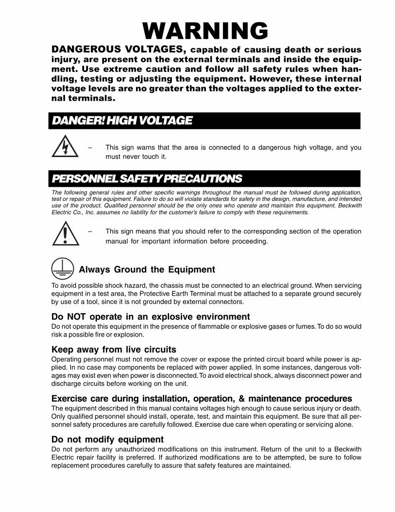
DANGER! HIGH VOLTAGE
– This sign warns that the area is connected to a dangerous high voltage, and youmust never touch it.
PERSONNEL SAFETY PRECAUTIONSThe following general rules and other specific warnings throughout the manual must be followed during application,test or repair of this equipment. Failure to do so will violate standards for safety in the design, manufacture, and intendeduse of the product. Qualified personnel should be the only ones who operate and maintain this equipment. BeckwithElectric Co., Inc. assumes no liability for the customer’s failure to comply with these requirements.
– This sign means that you should refer to the corresponding section of the operation
manual for important information before proceeding.
Always Ground the Equipment
To avoid possible shock hazard, the chassis must be connected to an electrical ground. When servicingequipment in a test area, the Protective Earth Terminal must be attached to a separate ground securelyby use of a tool, since it is not grounded by external connectors.
Do NOT operate in an explosive environmentDo not operate this equipment in the presence of flammable or explosive gases or fumes. To do so wouldrisk a possible fire or explosion.
Keep away from live circuitsOperating personnel must not remove the cover or expose the printed circuit board while power is ap-plied. In no case may components be replaced with power applied. In some instances, dangerous volt-ages may exist even when power is disconnected. To avoid electrical shock, always disconnect power anddischarge circuits before working on the unit.
Exercise care during installation, operation, & maintenance proceduresThe equipment described in this manual contains voltages high enough to cause serious injury or death.Only qualified personnel should install, operate, test, and maintain this equipment. Be sure that all per-sonnel safety procedures are carefully followed. Exercise due care when operating or servicing alone.
Do not modify equipmentDo not perform any unauthorized modifications on this instrument. Return of the unit to a BeckwithElectric repair facility is preferred. If authorized modifications are to be attempted, be sure to followreplacement procedures carefully to assure that safety features are maintained.

PRODUCT CAUTIONSBefore attempting any test, calibration, or maintenance procedure, personnel must be completely familiarwith the particular circuitry of this unit, and have an adequate understanding of field effect devices. If acomponent is found to be defective, always follow replacement procedures carefully to that assure safetyfeatures are maintained. Always replace components with those of equal or better quality as shown in theParts List of the Instruction Book.
Avoid static chargeThis unit contains MOS circuitry, which can be damaged by improper test or rework procedures. Careshould be taken to avoid static charge on work surfaces and service personnel.
Use caution when measuring resistancesAny attempt to measure resistances between points on the printed circuit board, unless otherwise notedin the Instruction Book, is likely to cause damage to the unit.
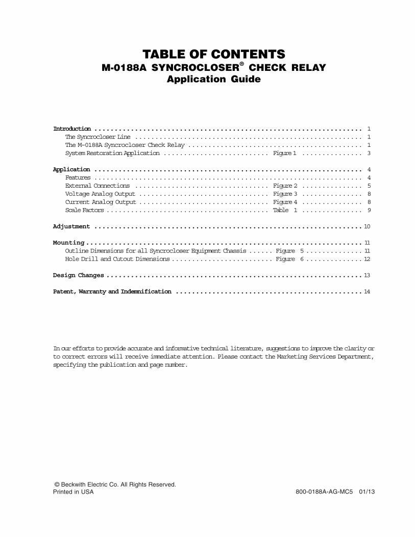
TABLE OF CONTENTSM-0188A SYNCROCLOSER® CHECK RELAY
Application Guide
Introduction .................................................................. 1The Syncrocloser Line ........................................................ 1The M–0188A Syncrocloser Check Relay ........................................... 1System Restoration Application .......................... Figure 1 ............... 3
Application .................................................................. 4Features .................................................................. 4External Connections ................................. Figure 2 ............... 5Voltage Analog Output ................................ Figure 3 ............... 8Current Analog Output ................................ Figure 4 ............... 8Scale Factors ........................................ Table 1 ............... 9
Adjustment ..................................................................10
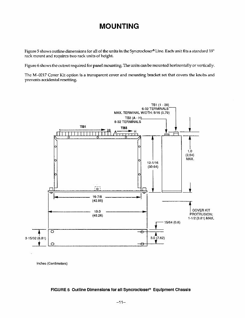
Mounting.................................................................... 11Outline Dimensions for all Syncrocloser Equipment Chassis ...... Figure 5 .............. 11Hole Drill and Cutout Dimensions......................... Figure 6 ..............12
Design Changes ...............................................................13
Patent, Warranty and Indemnification ..............................................14
In our efforts to provide accurate and informative technical literature, suggestions to improve the clarity orto correct errors will receive immediate attention. Please contact the Marketing Services Department,specifying the publication and page number.
800-0188A-AG-MC5 01/13 © Beckwith Electric Co. All Rights Reserved.Printed in USA

This Page Left Intentionally Blank


This Page Left Intentionally Blank

Legal Information
PatentThe units described in this manual are covered byU.S. Patent 4.218.625, with other patents pending.
Buyer shall hold harmless and indemnify the Seller,its directors, officers, agents, and employees fromany and all costs and expense, damage or loss,resulting from any alleged infringementof UnitedStates Letters Patent or rights accruing thereform ortrademarks, whether federal, state, or common law,arising from the Seller’s compliance with Buyer’sdesigns, specifications, or instructions.
WarrantySeller hereby warrants that the goods which are thesubject matter of this contract will be manufacturedin a good workmanlike manner and all materialsused herein will be new and reasonably suitable forthe equipment. Seller warrants that if, during aperiod of five years from date of shipment of theequipment, the equipment rendered shall be foundby the Buyer to be faulty or shall fail to peform inaccordance with Seller’s specifications of theproduct, Seller shall at his expense correct thesame, provided, however, that Buyers shall ship theequipment prepaid to Seller’s facility. The Seller’sresponsibility hereunder shall be limited to replace-ment value of the equipment furnished under thiscontract.
Seller makes no warranties expressed or impliedother than those set out above. Seller specificallyexcludes the implied warranties of merchantibilityand fitness for a particular purpose. There are nowarranties which extend beyond the descriptioncontained herein. In no event shall Seller be liable forconsequential, exemplary, or punitive damages ofwhatever nature.
Any equipment returned for repair must be sentwith transportation charges prepaid. The equipmentmust remain the property of the Buyer. The afore-mentioned warranties are void if the value of theunit is invoiced to the Seller at the time of return.
IndemnificationThe Seller shall not be liable for any propertydamages whatsoever or for any loss or damagearising out of, connected with, or resulting fromthis contract, or from the performance or breachthereof, or from all services covered by or furnishedunder this contract.
In no event shall the Seller be liable for special,incidental, exemplary, or consequential damages,including but not limited to, loss of profits orrevenue, loss of use of the equipment or anyassociated equipment, cost of capital, cost ofpurchased power, cost of substitute equipment,facilities or services, downtime costs, or claims ordamages of customers or employees of the Buyerfor such damages, regardless of whether said claimor damages is based on contract, warranty, tortincluding negligence, or otherwise.
Under no circumstances shall the Seller be liablefor any personal injury whatsoever.
It is agreed that when the equipment furnishedhereunder are to be used or performed in connec-tion with any nuclear installation, facility, oractivity, Seller shall have no liability for anynuclear damage, personal injury, property damage,or nuclear contamination to any property located ator near the site of the nuclear facility. Buyer agreesto indemnify and hold harmless the Seller againstany and all liability associated therewith whatso-ever whether based on contract, tort, or otherwise.Nuclear installation or facility means any nuclearreactor and includes the site on which any of theforegoing is located, all operations conducted onsuch site, and all premises used for such opera-tions.
Notice:Any illustrations and descriptions by BeckwithElectric Co., Inc. are for the sole purpose ofidentification.
The drawings and/or specifications enclosed hereinare the proprietary property of Beckwith ElectricCo., Inc., and are issued in strict confidence;therefore, shall not be used as a basis of reproduc-tion of the apparatus described therein withoutwritten permission of Beckwith Electric Co., Inc.
No illustration or description contained hereinshall be construed as an express warranty ofaffirmation, promise, description, or sample, andany and all such express warranties are specificallyexcluded nor shall such illustration or descriptionimply a warranty that the product is merchantableor fit for a particular purpose. There shall be nowarranties which extend beyond those contained inthe Beckwith Electric Co., Inc. terms of sale.
All rights reserved by Beckwith Electric Co., Inc. No reproduction may be made without prior written approvalof the Company.

This Page Left Intentionally Blank

BECKWITH ELECTRIC CO., INC.6190 - 118th Avenue North • Largo, Florida 33773-3724 U.S.A.
PHONE (727) 544-2326 • FAX (727) [email protected]
www.beckwithelectric.comISO 9001:2008
© Beckwith Electric Co. All Rights Reserved.Printed in USA 800-0188A-AG-MC5 01/13