Application Experiment Ground Station Guidelines · Application Experiment Ground Station...
29
Application Experiment Ground Station Guidelines November 27, 2006
-
Upload
phungxuyen -
Category
Documents
-
view
231 -
download
0
Transcript of Application Experiment Ground Station Guidelines · Application Experiment Ground Station...
Application Experiment Ground Station Guidelines
November 27, 2006

Application Experiment Ground Station Guidelines (Nov. 27, 2006) i
Introduction These "Application Experiment Ground Station Guidelines" provide information on
the requirements of the earth station equipment for WINDS and may help in the preparation of experiment proposals. [Note] ABOUT UPDATES TO THIS PAPER
Some of the WINDS specifications are presented here as a reference only, and are subject to change as the WINDS design matures in the future. Any updates will be incorporated as necessary.

Application Experiment Ground Station Guidelines (Nov. 27, 2006) ii
Table of contents 1. Outline of WINDS 1
2. Network configuration using WINDS 2
2.1 ATM baseband switching mode 2
2.2 Bent-pipe TDMA mode 3
3. Terminal types and examples of link budget 5
3.1 Types of user terminals 5
3.2 Examples of link budget 6
4. Hardware requirement of user terminal 11
4.1 Functions of user terminal 11
4.2 Performance of RF equipment 13
4.3 Performance of baseband equipment [TBD] *
5. Outline of protocols 16
5.1 ATM baseband switching mode 16
5.2 Bent-pipe TDMA mode [TBD] *
6. Additional information 20
6.1 Examples of improvement of TCP performance 20
6.2 Issues of international frequency coordination 20
6.3 Requirements for common frequency usage with Fixed Wireless Access (FWA) systems 20
7. Example of development of prototype earth station 22
[Terminology] 24
* To be added in the revised edition.

Application Experiment Ground Station Guidelines (Nov. 27, 2006) 1
1. Outline of WINDS WINDS (Wideband InterNetworking engineering test and Demonstration Satellite) is an experimental
satellite enables communications at significantly higher data rates. The satellite employs very
advanced technologies described below in order to realize both very high data rate transmissions and
advanced broadband satellite networking.
1) Fixed multi-beam antenna (MBA) and Ka-band multi-port amplifier (MPA)
Japan and several areas in Southeast Asia are covered by MBA spot-beams. The MBA can
generate a narrow beam width (spot beam) to concentrate the energy of the transmitted and
received radio wave, and provide a required functions for high data rate satellite communications.
The MPA, used with MBA, amplifies the transmitting power of several channels (maximum 8ch)
simultaneously, and can allocate power for each channel arbitrarily. For the Ka band, it enables the
allocation of power to areas specified in the experiment plan to compensate for a significant
attenuation that may be caused by rainfall.
2) Ka-band active-phased array antenna (APAA)
The APAA antenna can steer beams electronically within +/-7 degrees in the north-south direction or
+/-8 degrees in the east-west direction from the sub-satellite point with a beam, and generate two
beams simultaneously. Areas not covered by MBA can access WINDS using the APAA. The
performance (EIRP, G/T) of the APAA is less than that of the MBA, so larger earth stations are
required for APAA access than for MBA access.
3) Onboard Switching Router(ABS : ATM Baseband Switch)
The ABS receives the data bursts sent by users, demodulates them, redirects them by destination
address attached in a header of the ATM cell, and transmits them to the destination user. Because
the ATM cells to be sent to the same beam are multiplexed in a downlink, the transmission power of
the satellite transponder can be used efficiently and layer 2 routing is performed at the same time.
4) Very Wide Bandwidth Transponder
The ABS can be bypassed in the WINDS transponder, which is called the "Bent-pipe TDMA Mode".
In this case, the full bandwidth transponder of 1.1GHz can be utilized. The users' data bursts are not
be demodulated onboard, but satellite switching can be performed by switching the IF-Switch in
satellite switched time division multiple access manner. (SS-TDMA)
Due to the advanced technologies described above, WINDS provides superb communications
capability in a variety of networking configurations, such as:
- Mesh type networking connecting many sites at high data rates (max. 1.5-155Mbps) and carrying
multimedia contents.
- Mesh or star type networking connecting several sites at very high data rates (1.2Gbps).

Application Experiment Ground Station Guidelines (Nov. 27, 2006) 2
* Remarks
Although WINDS provides very high data transmission rates, high throughput is not achieved in some
cases of Internet use. It degrades Transmission Control Protocol (TCP) performance, but the
degradation can be avoided by using TCP extension or Performance Enhancing Proxy (PEP)
technology. Information regarding this issue is described in section 6.1 (2).
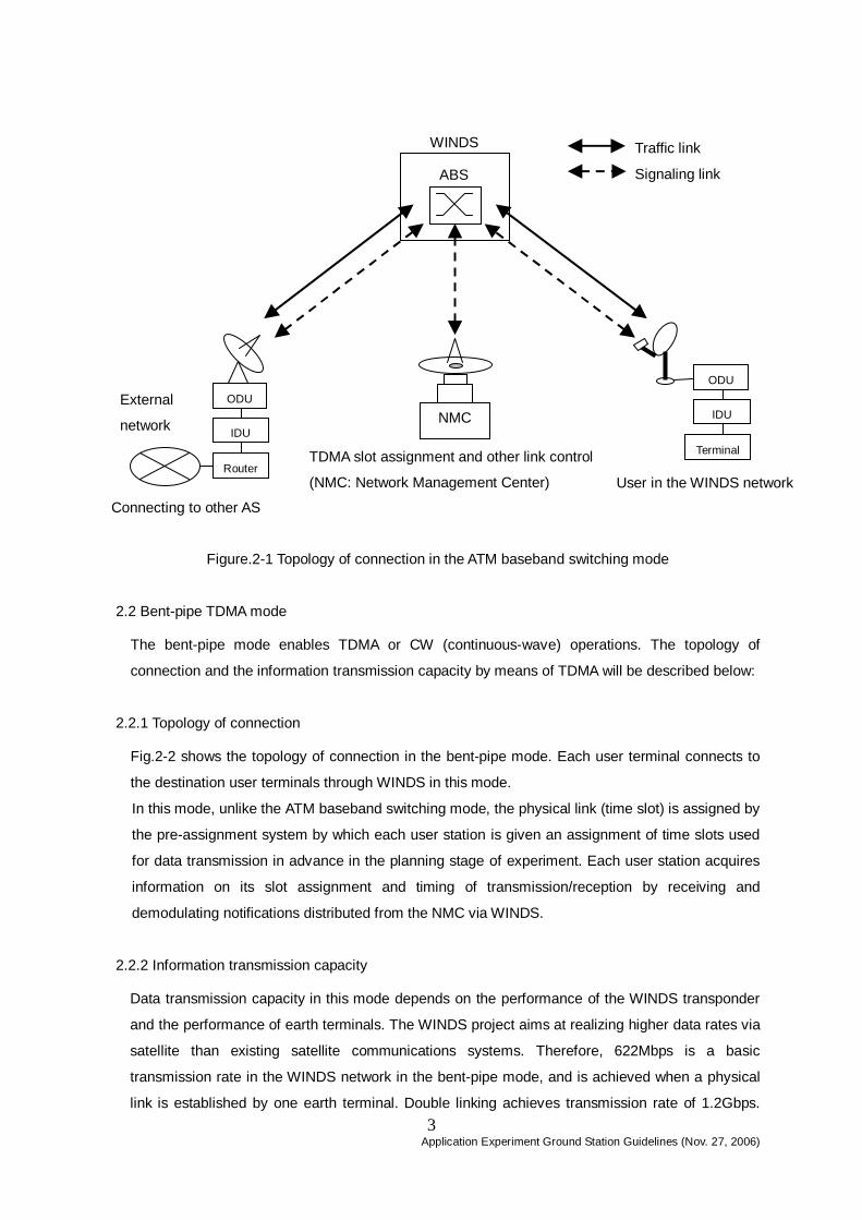
2. Network Configuration with WINDS 2.1 ATM baseband switching mode 2.1.1 Topology of connection
Figure.2-1 shows the connection topology in when the ATM baseband switching mode is used.
Here, each user terminal is logically connected to the ABS onboard the WINDS. The ABS
demodulates signals from user terminals, identifies the header of cells, and transfers association
cells and traffic data cells to the Network Management Center (NMC) and to destination user
terminals, respectively.
When user stations communicate with one another, first they are given an assignment of time slots
on a traffic link (data link) between them by means of a signaling link, and then transfer data
between them on the assigned time slots.
The signaling slot is pre-assigned for area, so the user terminal should use the assigned slot in the
area where the terminal is located. The association data must employ ATM layer protocol which the
ABS can treat, and SAAL protocol which the NMC employs.
Traffic data should be formatted as ATM cells which the ABS can treat, but upper layer protocols
are not specified by the WINDS network itself.
2.1.2 Information transmission capacity
In the ATM baseband switching mode, the information transmission capacity depends on the
performance of an ABS modulator/demodulator installed in WINDS, the transmission/reception
performance of a transponder in WINDS, and the transmission/reception performance of an earth
station. In the case of communication within Japan, the scale of an earth station to accommodate
the maximum information transmission rates of an uplink and a downlink will be described below:
a) Uplink
1.5 / 6 Mbps: Compact small terminal which can be installed at home (USAT)
24 / 51 Mbps: VSAT which can be installed in schools and SOHOs (1~2mø:HDR-VSAT), or
larger terminals (2~3mø: SDR-VSAT,≥5mø:LET)
155 Mbps: HDR-VSAT, SDR-VSAT or LET which can transmit three 51 Mbps signals.
b) Downlink
155 Mbps: All user terminals described in the uplink section.
Application Experiment Ground Station Guidelines (Nov. 27, 2006) 3
Figure.2-1 Topology of connection in the ATM baseband switching mode
2.2 Bent-pipe TDMA mode
The bent-pipe mode enables TDMA or CW (continuous-wave) operations. The topology of
connection and the information transmission capacity by means of TDMA will be described below:
2.2.1 Topology of connection
Fig.2-2 shows the topology of connection in the bent-pipe mode. Each user terminal connects to
the destination user terminals through WINDS in this mode.
In this mode, unlike the ATM baseband switching mode, the physical link (time slot) is assigned by
the pre-assignment system by which each user station is given an assignment of time slots used
for data transmission in advance in the planning stage of experiment. Each user station acquires
information on its slot assignment and timing of transmission/reception by receiving and
demodulating notifications distributed from the NMC via WINDS.
2.2.2 Information transmission capacity
Data transmission capacity in this mode depends on the performance of the WINDS transponder
and the performance of earth terminals. The WINDS project aims at realizing higher data rates via
satellite than existing satellite communications systems. Therefore, 622Mbps is a basic
transmission rate in the WINDS network in the bent-pipe mode, and is achieved when a physical
link is established by one earth terminal. Double linking achieves transmission rate of 1.2Gbps.
ABS
WINDS
NMC ODU
IDU Terminal
ODU
IDU External
network
Connecting to other AS
TDMA slot assignment and other link control
(NMC: Network Management Center) User in the WINDS network
Traffic link
Signaling link
Router

Application Experiment Ground Station Guidelines (Nov. 27, 2006) 4
(The technical challenge of achieving 1.2Gbps with single channel is now under study.) The
information necessary for setting a link is distributed as a notification to each user at a transmission
rate of 155Mbps. It is necessary to demodulate the notification information for TDMA
communication by means of the bent-pipe mode.
To achieve the above-mentioned transmission rate, basically an earth station (SDR-VSAT or LET)
of a scale of at least 2-3mø is necessary within Japan.
Figure. 2-2 Topology of connection in the bent-pipe TDMA mode
SW Matrix
WINDS
NMC ODU
IDU Terminal
ODU
IDU External
network
Connecting to another AS
TDMA slot assignment and another link control
(NMC: Network Management Center) User in the WINDS network
Traffic link
Signaling link
Router

Application Experiment Ground Station Guidelines (Nov. 27, 2006)
5
3. Terminal types and examples of link budget
3.1 Types of user terminals
The following table shows specified user terminal types for WINDS experiments.
Table 3-1 User terminal types for WINDS experiments
Type Description Applicable
operation mode
Maximum information rate
in uplink *1
Maximum information
rate in downlink
MBA1
MBA2
*2
APAA
*3
USAT ・Mini earth station that can be installed home
ATM baseband switching 1.5/6Mbps 155Mbps ○ △ ×
HDR-VSAT ・Small earth station that can be installed in schools, SOHO, etc.
ATM baseband switching
1.5/6/24/51/ 155(51 x 3ch)Mbps *4 155Mbps ○ △ △
ATM baseband
switching
1.5/6/24/51Mbps
155(51 x 3ch)Mbps *4 155Mbps ○ ○ ○
SDR-VSAT ・Medium size terminal for corporate
use Bent-pipe 622Mbps 622Mbps ○ △ △
ATM baseband
switching
1.5/6/24/51Mbps
155(51 x 3ch)Mbps *4 155 Mbps ○ ○ ○
LET
・Large scale terminal for installation
in large enterprises and research
organizations. Bent-pipe 622Mbps
1.2Gbps(622M x 2ch)
622Mbps
1.2Gbps (622M x 2ch) ○ △ △
△: This can be used subject to conditions. *1 In the case of ATM baseband switching, 1.5Mbps is needed for a signaling link, and, for a traffic link, any one of 1.5, 6, 24, 51 and 51 x 3 Mbps is used. *2 Assumed link availability is 98 %. Higher link availability requires a higher EIRP and G/T for the user terminal. *3 Because APAA's EIRP and G/T are smaller than those of MBAs, the G/T and EIRP of the user terminal should have a larger than those of MBAs. In
addition, the required EIRP and G/T differ slightly by area and location of earth terminal. *4 155Mbps (Uplink) requires 3 channels use of 51Mbps.

Application Experiment Ground Station Guidelines (Nov. 27, 2006) 6
3.2 Examples of link budget
Typical link budget calculations are shown in this section. Because rain attenuation depends on
the location of the earth station, these calculations are based on a clear sky condition. When
downlink rain attenuation occurs, increased noise temperature affecting the earth stations must be
considered for correct calculations. 1) ATM baseband switching link for USAT in MBA1 coverage(1.5/155Mbps)
Area Hokkaido East Beam (Nemuro)
Item unit uplink downlink
Freq. GHz 28.05 18.25
EIRP dBW 41.8 USAT 64.4 MBA1
Pointing Loss dB Included in EIRP
Free Space Loss dB -212.9 -209.2
Polarization Loss dB -0.2 -0.2
Absorption Loss dB -0.4 -0.2
Rain attenuation dB
Pointing Loss dB Included in G/T
G/T dB/K 17.7 MBA1 11.5 USAT
Rx C/No dB・Hz 74.6 94.9
Total C/No dB・Hz 74.6 94.9
Required C/No dB・Hz 73.6 93.9
Margin dB 1.0 1.0
Modulation QPSK QPSK
Required Eb/No dB 7.3 BER:5×10⁻⁴ 7.3 BER:5×10⁻⁴
Transmission
Degradation dB -2.7 -3.5
Bit rate * dB・Hz 63.6 2.3Mbps 83.1 204Mbps
Required C/No dB・Hz 73.6 93.9
* Actual bit rate becomes larger than the information bit rate because preamble, error correction code
and other redundant parts are added to the information bits to form a burst format.

Application Experiment Ground Station Guidelines (Nov. 27, 2006) 7
2) ATM baseband switching link for HDR-VSAT in MBA1 coverage(51/155Mbps)
Area Hokkaido East Beam (Nemuro)
Item unit uplink downlink
Freq. GHz 28.05 18.25
EIRP dBW 57.4* VSAT 57.5 MBA1
Pointing Loss dB -0.5 Included in EIRP
Free Space Loss dB -212.9 -209.2
Polarization Loss dB -0.2 -0.2
Absorption Loss dB -0.4 -0.2
Rain attenuation dB
Pointing Loss dB Included in G/T -0.5
G/T dB/K 17.7 MBA1 19.0 VSAT
Rx C/No dB・Hz 89.7 94.9
Total C/No dB・Hz 89.7 94.9
Required C/No dB・Hz 88.7 93.9
Margin dB 1.0 1.0
Modulation QPSK QPSK
Required Eb/No dB 7.3 BER:5×10⁻⁴ 7.3 BER:5×10⁻⁴
Transmission
Degradation dB -2.7 -3.5
Bit rate dB・Hz 78.7 74Mbps 83.1 204Mbps
Required C/No* dB・Hz 88.7 93.9
* In case of 51Mbps×3(=155Mbps)uplink, 4.8dB should be added.

Application Experiment Ground Station Guidelines (Nov. 27, 2006) 8
3) ATM baseband switching link for HDR-VSAT in MBA2 coverage (51/155Mbps)
Area Manila
Item unit uplink downlink
Freq. GHz 28.05 18.25
EIRP dBW 55.7* VSAT 57.1 MBA2
Pointing Loss dB -0.5 Included in EIRP
Free Space Loss dB -212.7 -208.9
Polarization Loss dB -0.2 -0.2
Absorption Loss dB -0.3 -0.2
Rain attenuation dB
Pointing Loss dB Included in G/T -0.5
G/T dB/K 19.0 MBA2 19.0 VSAT
Rx C/No dB・Hz 89.7 94.9
Total C/No dB・Hz 89.7 94.9
Required C/No dB・Hz 88.7 93.9
Margin dB 1.0 1.0
Modulation QPSK QPSK
Required Eb/No dB 7.3 BER:5×10⁻⁴ 7.3 BER:5×10⁻⁴
Transmission
Degradation dB -2.7 -3.5
Bit rate* dB・Hz 78.7 74Mbps 83.1 204Mbps
Required C/No* dB・Hz 88.7 93.9* In case of 51Mbps×3(=155Mbps)uplink, 4.8dB should be added.

Application Experiment Ground Station Guidelines (Nov. 27, 2006) 9
4) Bent-pipe link for SDR-VSAT in MBA1 coverage (622 Mbps)
Area Hokkaido East Beam (Nemuro)
Item unit Uplink downlink
Freq. GHz 28.05 18.25
EIRP dBW 72.6 SDR-VSAT 65.2 MBA1
Power Allocation Loss dB
Pointing Loss dB -0.5
Free Space Loss dB -212.9 -209.2
Polarization Loss dB -0.2 -0.2
Absorption Loss dB -0.4 -0.2
Rain Attenuation dB
Pointing Loss dB -0.5
G/T dB/K 17.7 MBA1 24.5 SDR-VSAT
Rx C/No dB・Hz 104.9 Included in MBA 108.1
Total C/No dB・Hz 103.2
Required C/No dB・Hz 100.2
Margin dB 3.0
Modulation QPSK
Required Eb/No dB 7.3 BER:5 x 10⁻⁴
Transmission
Degradation dB -4.0
Bit Rate dB・Hz 88.9 782Mbps
Required C/No dB・Hz 100.2

Application Experiment Ground Station Guidelines (Nov. 27, 2006) 10
5) Bent-pipe link for LET in APAA coverage (622 Mbps)
Area Sydney (1 beam operation)
Item unit uplink downlink
Freq. GHz 28.05 18.25
EIRP dBW 80.1 LET 55.3 APAA
Pointing Loss dB -0.5 -0.9
Free Space Loss dB -212.8 -209.1
Polarization Loss dB -0.2 -0.2
Absorption Loss dB -0.3 -0.2
Rain Attenuation dB
Pointing Loss dB -0.9 -0.5
G/T dB/K 8.7 APAA 34.1 LET
Rx C/No dB・Hz 102.7 107.1
Total C/No dB・Hz 101.4
Required C/No dB・Hz 100.2
Margin dB 1.1
Modulation QPSK
Required Eb/No dB 7.3 BER:5×10⁻⁴
Transmission
degradation dB -4.0
Bit Rate dB・Hz 88.9 782Mbps
Required C/No dB・Hz 100.2
Application Experiment Ground Station Guidelines (Nov. 27, 2006) 11
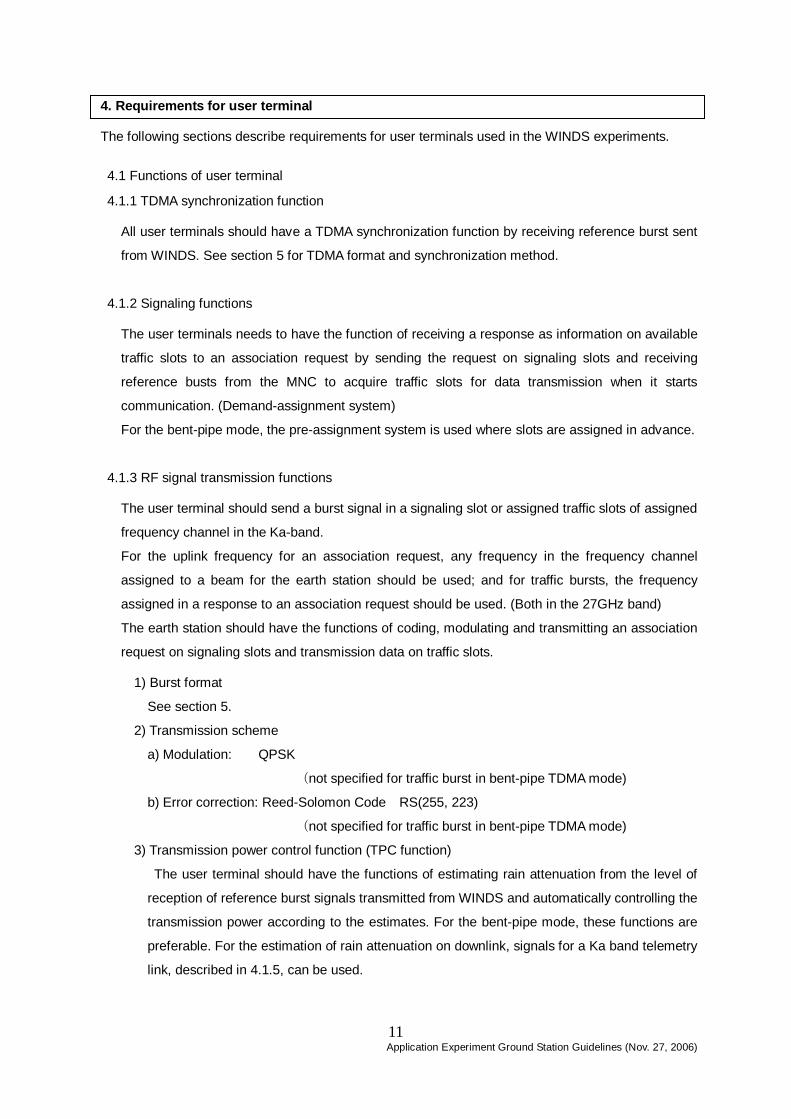
4. Requirements for user terminal The following sections describe requirements for user terminals used in the WINDS experiments. 4.1 Functions of user terminal 4.1.1 TDMA synchronization function
All user terminals should have a TDMA synchronization function by receiving reference burst sent
from WINDS. See section 5 for TDMA format and synchronization method.
4.1.2 Signaling functions
The user terminals needs to have the function of receiving a response as information on available
traffic slots to an association request by sending the request on signaling slots and receiving
reference busts from the MNC to acquire traffic slots for data transmission when it starts
communication. (Demand-assignment system)
For the bent-pipe mode, the pre-assignment system is used where slots are assigned in advance.
4.1.3 RF signal transmission functions
The user terminal should send a burst signal in a signaling slot or assigned traffic slots of assigned
frequency channel in the Ka-band.
For the uplink frequency for an association request, any frequency in the frequency channel
assigned to a beam for the earth station should be used; and for traffic bursts, the frequency
assigned in a response to an association request should be used. (Both in the 27GHz band)
The earth station should have the functions of coding, modulating and transmitting an association
request on signaling slots and transmission data on traffic slots.
1) Burst format
See section 5.
2) Transmission scheme
a) Modulation: QPSK
(not specified for traffic burst in bent-pipe TDMA mode)
b) Error correction: Reed-Solomon Code RS(255, 223)
(not specified for traffic burst in bent-pipe TDMA mode)
3) Transmission power control function (TPC function)
The user terminal should have the functions of estimating rain attenuation from the level of
reception of reference burst signals transmitted from WINDS and automatically controlling the
transmission power according to the estimates. For the bent-pipe mode, these functions are
preferable. For the estimation of rain attenuation on downlink, signals for a Ka band telemetry
link, described in 4.1.5, can be used.

Application Experiment Ground Station Guidelines (Nov. 27, 2006) 12
4) Automatic Frequency Control (AFC) Function
The user terminal should provide control of the assigned transmitting frequency.
4.1.4 RF Signal reception function
The user terminal should receive, demodulate and decode reference bursts transmitted on
signaling slots, and traffic burst signals for its area. It should also identify an ATM cell header in the
decoded signals to extract the data addressed to it. Down link frequency is 18GHz band.
1) Burst format
See section 5.
2) Transmission scheme
a) Modulation: QPSK
(not specified for traffic burst in bent-pipe TDMA mode)
b) Error correction: Reed-Solomon Code RS(255, 223)
(not specified for traffic burst in bent-pipe TDMA mode)
4.1.5 Satellite tracking function (this applies only to SDR-VSAT and LET)
The earth station should be capable of tracking the WINDS satellite by using the residual carrier of
signals for a Ka band telemetry link transmitted from the satellite. (The Ka band telemetry link is a
separate link provided for the monitoring of the state of mission equipment onboard satellite.)
The specifications for signals for the Ka band telemetry link (downlink) are as follows.
a) Frequency: 18.9GHz band
b) Transmission EIRP: 17.2dBW (θ < 6deg.), 15.7dBW (θ < 8deg.)
*θ is an angle of the earth station to the subsatellite point as zero
degree (a half of the vertex angle at the satellite).
c) Polarization: RHCP
d) Modulation: PCM (NRZ-L)/PSK/PM
e) Sub-carrier frequency: 40 KHz
f) Modulation depth : 1.1rad ± 10% or less
g) Data rate of information: 10kbps
4.1.6 Base-band interface function
The user terminal needs to have a base-band interface with the equipment, such as data terminals
and routers, that the user uses. This function depends on the equipment that the user uses, so the
user is required to confirm the specifications and performance by itself.

Application Experiment Ground Station Guidelines (Nov. 27, 2006) 13
4.2 Specifications of RF equipment
Table 4-1 shows the specifications of the RF part of the earth station. Fig. 4-1 shows the
transmission and reception frequencies (provisionally specified).
UPLINK27.537
27.592527.648 27.722
27.777527.833 27.907
27.962528.018
28.33 BCN28.75
PIL28.8
NIL28.9
275MHz 270MHz37MHz
55.5MHz
55.5MHz
74MHz
55.5MHz
55.5MHz
74MHz
55.5MHz
55.5MHz
37MHz
11.5625MHz
11.5625MHz
32.375MHz
2.3125MHz
NIL18.917.7925 17.9775 18.1625 18.53
270MHz
367.5MHz
92.5MHz
185MHz
185MHz
DOWNLINK
1.5Mbps再生中継回線
6、24、51Mbps再生中継回線
155Mbps再生中継回線
622Mbps非再生中継回線
Figure. 4-1 Transmission/reception frequencies (provisionally specified)
Ka telecommand
1.5 Mbps ATM baseband switching link
6, 24 or 51 Mbps ATM baseband switching link
155 Mbps ATM baseband switching link
622 Mbps bent-pipe TDMA link
Ka telemetry

Application Experiment Ground Station Guidelines (Nov. 27, 2006)
14
Table 4-1 Specifications of RF User Terminal Equipment
USAT HDR-VSAT SDR-VSAT LET
Transmitting frequency 27GHz band (tentative)
Stability of transmitting frequency ≤1×10⁻⁷ ≤1×10⁻⁷ ≤1×10⁻⁷ ≤1×10⁻⁷
Receiving frequency 18GHz band (tentative)
EIRP (linear operation) ≥ 48.8dBW *1 ≥ 66.9dBW *2 ≥ 75.4dBW ≥ 80.2dBW
G/T ≥ 11.5dB/K ≥ 19.0dB/K ≥ 24.5dB/K ≥ 32.0dB/K
Dynamic range of receiving signal ≥ 10.0dB ≥ 10.0dB TBD TBD Polarization Vertical or Horizontal (Linear)
Separation of polarization ≥ 20dB ≥25dB TBD TBD Side lobe To meet ITU-Rrec. S580-5
Off-axis emission To meet ITU-Rrec. S524-8
RF frequency-amplitude characteristics TX: ≤ ±0.7dB/6.4MHz TX: ≤ ±1.0dB/51.8MHz ≤ 0.75dB/500MHz ≤ 0.75dB/500MHz
RF frequency-phase characteristics TX: ≤ ±0.1dB/6.4MHz TX: ≤ ±0.2dB/51.8MHz ≤ 1nsec/300MHz ≤ 1nsec/300MHz
RF phase noise characteristics TX: ≤ 3deg.rms
(less than 20kHz-4.6MHz)
TX: ≤ 3deg.rms
(less than 20kHz-37MHz) ≤ -60 dBc at 1kHz from center frequency
≤ -70 dBc at 10 kHz from center
* 1: In the case of up-link maximum information transmission rates (6Mbps), * 2: In the case of up-link maximum information transmission rates (51x3Mbps)
[Attention]
ITU-R specifies off-axis emission power density of earth station in order to avoid interference between satellite networks. User terminal should reflect this
recommendation, especially the antenna diameter is very small.
Refer to the attached information on ITU-R recommendations regarding off-axis EIRP of earth station (S.524-8)

Application Experiment Ground Station Guidelines (Nov. 27, 2006) 15
Excerpts of RECOMMENDATION ITU-R S.524-8
Recommends 4-That earth stations operating in GSO networks in the FSS operating in the
27.5-30 GHz frequency band be designed in such a manner that at any angle, ϕ, which is 2° or more
off the main lobe axis of an earth station antenna, the e.i.r.p. density in any direction within 3° of the
GSO should not exceed the following values:
Angle off-axis Maximum e.i.r.p. per 40 kHz
2° ≤ ϕ ≤7° (19 – 25 log ϕ) dB(W/40 kHz)
0 7° < ϕ ≤9.2° –2 dB (W/40 kHz)
0 9.2°< ϕ ≤48° (22 – 25 log ϕ) dB(W/40 kHz)
48° < ϕ ≤180° –10 dB (W/40 kHz).
For any direction in the region outside 3° of the GSO, the above limits may be exceeded by no more
than 3 dB;
NOTE 21 – In the frequency range 27.5-29.0 GHz for earth stations whose antenna diameter is less
than 65 cm, the off-axis e.i.r.p. density levels given in recommends 4 may be exceeded by up to 3 dB
provided that the maximum off-axis e.i.r.p. density does not exceed the following values:
Angle off-axis Maximum e.i.r.p. per 2 MHz
2° ≤ ϕ ≤7° (37 – 25 log ϕ − 10 log M) dB(W/2 MHz)
7° < ϕ ≤9.2° (16 − 10 log M) dB(W/2 MHz)
9.2°< ϕ ≤48° (40 – 25 log ϕ − 10 log M) dB(W/2 MHz)
48° < ϕ ≤180° (7 − 10 log M) dB(W/2 MHz).
Where M is the number of earth stations which are in the receive beam of the satellite to which these
earth stations are communicating and which are expected to transmit simultaneously in the same 2
MHz band and in the same polarization. It should be noted that for these cases a reduction in e.i.r.p.
density, or additional orbital separation, would be required in order to arrive at the same adjacent
satellite interference in the Earth-to-space direction as would result from the off-axis e.i.r.p., values as
specified in recommends 4.

Application Experiment Ground Station Guidelines (Nov. 27, 2006) 16
5. Outline of protocols 5.1 ATM baseband switching mode
In this mode, all user terminals should be synchronized to the ABS onboard WINDS, and a user
terminal can transmit signal in assigned signaling slot and assigned traffic slots. The following
section outlines processing procedure.
5.1.1 Synchronization method
1) TDMA Frame
In the ATM baseband switching mode, the TDMA frame structure shown in Figure.5.1-1 is
employed for all of frequency channels. The basic frame consists of 20 time slots whose duration
is constantly 2msec. The first slot of the basic frame, the "Signaling Slot (SS)" is used to send the
Association Request burst from users in uplink and to send the Reference Burst to provide notice
of slot assignment control and ABS status in downlink. The 19 other time slots, called “Traffic
Slots” and assigned to users according to user' requirement are used for data transmission
between users.
A Super Frame consists of the 16 basic frames described above. Each signaling slot in the 16
frames of a Super Frame is pre-assigned to 16 areas on the Earth. In other words, the WINDS
network can provide communications services to 16 areas, and users in the 16 areas can send an
association request once in a Super Frame, and then send data in the assigned Traffic Slots.
Super Frame = 16 Frames (640 msec)
Frame = 20 Slots (40 msec)
• • • • •
• • • • • • •Frame#1 Frame#2 Frame#3 Frame#4 Frame#16
SS TS#1 TS#2 TS#3 TS#4 TS#19 SS : Signaling SlotTS : Traffic Slot 2 msec
SS in Frame#n isassigned to Area#n. TSs in a Super Frame are assigned to user data traffic
dianmically.フレーム#nの SS は
エリア#nに割り当
てられている.
スーパーフレーム中のTS はダイナミックにユーザ間
データ転送用に割り当てられる.
2 msec
2) Outline of synchronization
The WINDS network requires that all user terminals be synchronized to the WINDS network. The
Reference Burst (RB) is used to synchronize user terminals. As mentioned in the previous section,
the RB is sent to define users once in a Super Frame. The first part of the RB contains a 32 bit
Figure. 5.1-1 TDMA Frame Structure (ATM baseband switching Mode)

Application Experiment Ground Station Guidelines (Nov. 27, 2006) 17
code (Unique Word) for timing detection, and a user terminal can detect the Super Frame using
this bit sequence. Because each user terminal should know the order of the receiving RB in a
Super Frame, the user terminal can determine the starting point of the receiving Super Frame.
The frame timing can be obtained by dividing the Super Frame by 16. In addition, the slot timing
can be obtained by dividing the Frame timing by 20. Once the receiving timing is obtained,
transmitting timing can be obtained using satellite orbit information and physical allocation of the
user terminal. The orbit information of the WINDS satellite is also contained in every RB.
The user terminal must not be used to transmit a signal if it receives RBs. (Inter-locking function)
5.1.2 Connection control method
1) Association burst
When a user starts communication, the user terminal sends an association burst including
connection request information to the signaling slot assigned to the user’s area. When more than
one earth station sends requests for association at the same time, there can be competition for
association. So the earth station needs to be capable of retransmitting an association request
after a random wait time.
2) Assignment of traffic slots
The connection request from users included in the association bursts is transmitted to the
network management center (NMC) in the Tsukuba Space Center via ABS. The NMC assigns
traffic slots to users based on the request, current assignment status, satellite power allocation
situation, and other parameters. The determined slot assignment information is delivered by RB
to user terminals.
The user terminal should recognize the assigned user traffic slots from the assignment
information in RB, after which the user terminal is permitted to send data bursts to the destination
user terminal using only the assigned traffic slots.
3) Connection termination
When a user terminal ends communication with a destination user terminal, its terminal should
send an Association termination request burst using ATM cell (VPI/VCI to NMC) toward the NMC.
The NMC should terminate the connection based on the Association termination request, and
release the assigned traffic slots for connection.
5.1.3 Burst format
Figure. 5.1-2 shows the burst format. Both the association burst, RB and traffic burst employ this
format which enables transmitting in the 2msec time slot.

Application Experiment Ground Station Guidelines (Nov. 27, 2006) 18
HDR TRL
Info#n RS#n
HDR : Header ヘッダ PA : Preamble プリアンブル CR : Carrier Recovery 搬送波再生部
BTR : Bit Timing Recovery ビットタイミング再生部
UW : Unique Word ユニークワード DB #n : n-th Data Block 第nデータブロック
TRL : Trailer トレイラ GT : Guard Time ガードタイム
DB#1 DB#NDB#n
Cell1 Cell2 Cell3 Cell4 Pad
GT
Info#n : n-th Information 第n情報RS #n : n-th Reed-Solomon Code
第nリードソロモン符号Cell : ATM Cell Pad : Padding パディングビット
223 Bytes
32 Bytes
2 msec
PA UW
CR BTR
BTR
Uplink
Downlink
CR = all ‘0’ BTR = “0011- - - “
BTR = “00101101- - - “50 Bytes
Figure.5.1-2 Burst Format
A header and trailer are added to the main body of a burst in order to cancel the transient response
of the circuit. The bit sequence for these parts is all "0s" for the uplink and the same sequence as
BTR for the downlink. The number of data block varies according to transmission rate. Each data
block consists of an information field of 223Bytes and 32Bytes Reed-Solomon code. The addition of
a header, trailer, Reed-Solomon code and guard time makes the actual transmission rate higher
than the information rate. The "symbol rate" is defined as the half rate of this actual transmission
rate because QPSK is used as the modulation scheme. These parameters are shown in table 5.1-1.
Table 5.1-1 Burst transmission Parameters
Up / Down Information rate Nh*1 Nt*2 N*3 Symbol rate
Uplink 1.5 Mbps 2 2 2 1.15625Msps
6Mbps 2 2 8 4.625Msps
24Mbps 4 4 30 18.5Msps
51Mbps 8 8 60 37Msps
Downlink 155Mbps 144 656 180 101.75Mbps
*1 : Number of header bits,*2 : Number of trailer bits,*3 : Number of data blocks
Pre-amble for uplink burst consists of 200 bits of carrier recovery (CR) and 200 bits of bit timing
recovery (BTR). Pre-amble for downlink burst consists of 400 bits of BTR only. Bit sequence of
these pre-amble are shown in Figure. 5.1-2.
Unique words (UW) for reference burst (RB) are distinguished from other burst in order to identify

Application Experiment Ground Station Guidelines (Nov. 27, 2006) 19
the RB, because the UW in RB is used to detect super frame timing. The bit sequence of those UWs
is shown in table 5.1-2.
Table 5.1-2 Bit Sequence of Unique Words
Type of Burst I-channel Q-channel
Reference Burst 1100101111000100 (0xCBC4) 0011010000111011 (0x343B)
Traffic Burst 1011011100000110 (0xB706) 0100100011111001 (0x48F9)
Association Burst same as traffic burst same as traffic burst

Application Experiment Ground Station Guidelines (Nov. 27, 2006) 20
6. Additional information 6.1 Examples of improvement of TCP performance
It is known that the throughput of Transport Control Protocol (TCP) is markedly degraded much
over a satellite link with a long delay or a very high speed fiber optic link (so called "long fat pipe")..A
few solutions, described below, have been developed to solve this problem.
1) TCP Extension
The Internet Engineering Task Force (IETF) has developed TCP Extension technique to overcome
the degradation of TCP throughput. This technique is opened as RFC-1323, RFC-2018 and
RFC-2488, and many workstations employ these RFCs. TCP throughput can be improved by
making these TCP extensions active before beginning experiments.
2) Using special protocol for satellite link
The TCP extension described above, however, cannot eliminate degradation by "slow start"
process or "congestion control" mechanism. To solve this issue, another technique using a
different protocol dedicated to the satellite links has been developed. Here, protocol conversion
between common TCP/IP and the dedicated protocol should be done at the edge of the satellite
links. The equipment for protocol conversion is called "Performance Enhancing Proxy (PEP)". One
such popular dedicated protocol is "express transport protocol (XTP)", and PEP using XTP is
commercially available. This technique still raises a few issues however such as:
- when an error occurs in satellite links, the reliability of information transmission between
terminals at both ends is not guaranteed,
- protocol conversion is not possible if IPSec is employed.
6.2 Issues of international frequency coordination
Satellite network utilizing WINDS is under international coordination. For this purpose, earth
stations listed below are submitted.
Type of earth
stations
Antenna pattern Maximum
transmitting
power(dBW)
Maximum transmitting
power density at antenna
input (dBW/Hz)
USAT 29-25logθ 12.5 -48.1
HDR-VSAT 29-25logθ 19.3 -41.3
SDR-VSAT 29-25logθ 23.2 -37.4
LET 29-25logθ 23.2 -37.4
6.3 Requirements for common frequency usage with Fixed Wireless Access (FWA) systems
Note that care is necessary with regard to interference between the WINDS satellite network and

Application Experiment Ground Station Guidelines (Nov. 27, 2006) 21
FWA. It is recommended that you check the laws and recommendations concerning requirements
for common frequency usage with the FWA in your location.
Application Experiment Ground Station Guidelines (Nov. 27, 2006)
22
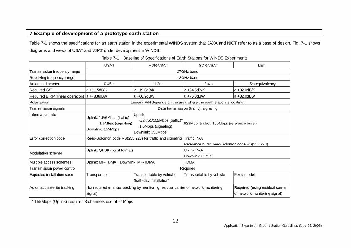
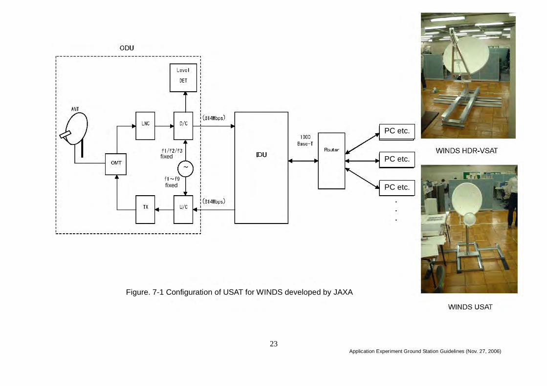
7 Example of development of a prototype earth station Table 7-1 shows the specifications for an earth station in the experimental WINDS system that JAXA and NICT refer to as a base of design. Fig. 7-1 shows
diagrams and views of USAT and VSAT under development in WINDS.
Table 7-1 Baseline of Specifications of Earth Stations for WINDS Experiments
USAT HDR-VSAT SDR-VSAT LET Transmission frequency range 27GHz band Receiving frequency range 18GHz band Antenna diameter 0.45m 1.2m 2.4m 5m equivalency Required G/T ≥ +11.5dB/K ≥ +19.0dB/K ≥ +24.5dB/K ≥ +32.0dB/K Required EIRP (linear operation) ≥ +48.8dBW ≥ +66.9dBW ≥ +76.0dBW ≥ +82.0dBW Polarization Linear ( V/H depends on the area where the earth station is locating) Transmission signals Data transmission (traffic), signaling Information rate
Uplink: 1.5/6Mbps (traffic) 1.5Mbps (signaling)
Downlink: 155Mbps
Uplink: 6/24/51/155Mbps (traffic)*1.5Mbps (signaling)
Downlink: 155Mbps
622Mbp (traffic), 155Mbps (reference burst)
Error correction code Reed-Solomon code RS(255,223) for traffic and signaling Traffic: N/A Reference burst: reed-Solomon code RS(255,223)
Modulation scheme Uplink: QPSK (burst format) Uplink: N/A
Downlink: QPSK Multiple access schemes Uplink: MF-TDMA Downlink: MF-TDMA TDMA Transmission power control Required Expected installation case Transportable Transportable by vehicle
(half -day installation) Transportable by vehicle Fixed model
Automatic satellite tracking Not required (manual tracking by monitoring residual carrier of network monitoring signal)
Required (using residual carrier of network monitoring signal)
* 155Mbps (Uplink) requires 3 channels use of 51Mbps
Application Experiment Ground Station Guidelines (Nov. 27, 2006)
23
Fig. 7-1 Configuration of USAT for WINDS developed by JAXA
全面差し替え
PC etc.
PC etc.
PC etc.
Figure. 7-1 Configuration of USAT for WINDS developed by JAXA
fixed
fixed

Application Experiment Ground Station Guidelines (Nov. 27, 2006) 24
[Terminology]
ABS ATM Baseband Switch : high speed ATM switch on-board WINDS
APAA
Active Phased Array Antenna : Electronically steerable beam antenna which
has antenna array with amplifiers and phase shifters
AS
Autonomous System:An Internet unit network in independently controlled by
a single administrator.
Association
request
Information with which the user station notifies a reference station of a
connection request
ATM
Asynchronous Transfer Mode:Layer-2 protocol commonly used in
broadband networks. Featuring advanced QoS control or friendliness to
multi-media communication.
EIRP Equivalent Isotropic Radiated Power
G/T Gain to noise temperature ratio
HDR-VSAT High Data Rate Very Small Aperture Terminal
IETF
Internet Engineering Task Force: A group researching Internet technology to
be used as standards.
IF Switch
Onboard switch to change the path inside WINDS in down converted
intermediate frequency (not regenerative)
IP Internet Protocol
LET Large-scale Earth Terminal
MPA Multi-Port Amplifier: An amplifier with several input and output ports.
QPSK Quadrature Phase Shift Keying (modulation scheme)
SAAL Signaling ATM Adaptation Layer
SDR-VSAT Super high Data Rate Very Small Aperture Terminal
TCP Transport Control Protocol
TPC Transmission Power Control
USAT Ultra Small Aperture Terminal
WINDS Wideband InterNetworking engineering test and Demonstration Satellite
Signaling slot
Time slot dedicated to sending association request burst or reference burst
located at the first part of each TDMA frame.
Association
request burst
A burst which a user sends to the network control station (NMC) to notify it of
connection request.
Uplink Link from earth station to the WINDS
Area Physical area on the earth surface covered by a WINDS antenna beam.
Link availability
Percentage of communication link that can be used. (time which the link
suffers from rain attenuation or other reason is eliminated)

Application Experiment Ground Station Guidelines (Nov. 27, 2006) 25
Network Management Center (NMC)
An earth station dedicated to control of the WINDS network, which it is
planned will be located at the Tsukuba Space Center of JAXA.
Signaling Connection control between user terminals such as connect, release, etc.
Information rate
Transmission rate of user information. Physical bit rate becomes larger
than information rate because redundant bits such as error correction code
are added to user information.
Throughput Efficiency of link usage.
Slot A unit of time sliced. WINDS defines a slot as 2 msec duration.
Cell
Data transmission block in ATM protocol. A cell consists of 5 Bytes (octet)
of header and a 48 Bytes(octet) data field.
Downlink Link from the WINDS to earth stations
Long fat pipe Communication link with a large delay-bandwidth product.
Traffic Exchange of data between users.
Traffic burst A burst which carries data between users.
Traffic data Information transmitted between users.
Beam
A number of radio wave sent from an antenna. (Multi-beam antenna has
multiple beams.)
Protocol
Rules of communication. Procedure of data transmission, modulation
scheme, error recovery and other rules are specified in a protocol.
Baseband Digital bit stream not modulated.
Header Information added to the beginning of a data block for control.
Reference burst
A burst sent from the NMC or ABS to the user terminal which contains the
sync-code, slot assignment information, operation status of network, satellite
orbit information, and so on.
Routing Selection or setting up of path of communication.
Layer 2 Link layer of Open System Interconnection (OSI) model specified by ISO.
Signaling slot
For uplink, time slot on which the user transmits an association request; and
for downlink, time slot on which reference bursts are transmitted

Application Experiment Ground Station Guidelines (Nov. 27, 2006) 26
Application Experiment Ground Station Guidelines
The First Edition December 10, 2003 The Second Edition November 27, 2006
Secretariat Space Communications Research Office
Information and Communications Policy Bureau Ministry of Internal Affairs and Communications
Central Common Government Office, No. 2 Bldg., 11th floor
2-1-2 Kasumigaseki, Chiyoda-ku, Tokyo 100-8926, Japan
Email [email protected]