Application description y 07/2014 5-axis circular pocket ... · PDF fileApplication...
19
http://support.automation.siemens.com/WW/view/en/90277865 Application description 07/2014 5-axis circular pocket-hole milling SINUMERIK 840D sl
Transcript of Application description y 07/2014 5-axis circular pocket ... · PDF fileApplication...

http://support.automation.siemens.com/WW/view/en/90277865
Application description 07/2014
5-axis circular pocket-holemillingSINUMERIK 840D sl

Warranty and liability
5-axis circular pocket hole millingEnty ID: 90277865, V1.0, 07/2014 2
Siem
ens
AG20
14Al
lrig
hts
rese
rved
Warranty and liability
Note The application examples are not binding and do not claim to be completeregarding the circuits shown, equipping and any eventuality. The applicationexamples do not represent specific customer solutions; they are intended only assupport for typical tasks. You are responsible for ensuring that the productsdescribed are used correctly. These application examples do not relieve you ofthe responsibility in safely and professionally using, installing, operating andservicing equipment. By using these application examples, you agree thatSiemens cannot be made liable for possible damage beyond the liability clausedescribed. We reserve the right to make changes to these application examplesat any time and without prior notice. If there are any differences between thesuggestions made in these application examples and other Siemens publicationssuch as catalogs, the contents of the other document(s) take priority.
We give no guarantee that the information contained in this document is complete,accurate, or up-to-date.We accept no liability for any damage or loss caused by the examples, information,programs, planning data or performance data described in this applicationexample, irrespective of the legal basis for claims arising from such damage orloss, unless liability is mandatory. For example, according to the product liabilitylaw, in cases of malfeasance, gross negligence, due to endangerment of life, bodyor health, due to assumption of a guarantee for a product's characteristics of state,due to malicious concealment of a defect or due to violation of basic contractualobligations. Any compensation for violation of basic contractual obligations,however, shall be limited to the foreseeable damage or loss which is typicallyenvisaged in contracts unless there has been gross negligence or unless liability ismandatory due to endangerment of life, body, or health. Any change to the burdenof proof to your disadvantage is not covered hereby.Any form of duplication of these application examples or excerpts hereof is notpermitted without the express consent of Siemens Industry Sector.
Securitynotes
Siemens provides products and solutions with industrial security functions thatsupport the secure operation of plants, solutions, machines, devices, and/ornetworks. They are important components in a holistic industrial securityconcept. With this in mind, Siemens’ products and solutions undergo continuousdevelopment. Siemens recommends strongly that you regularly check forproduct updates.
To ensure that Siemens products and solutions are operated securely, suitablepreventive measures (e.g. cell protection concept) must be taken and eachcomponent must be integrated into a state-of-the-art holistic industrial securityconcept. Third-party products that may be in use should also be considered. Formore information about industrial security, visithttp://www.siemens.com/industrialsecurity
To receive information about product updates on a regular basis, register for ourproduct newsletter. For more information, visithttp://support.automation.siemens.com

Table of Contents
5-axis circular pocket hole millingEnty ID: 90277865, V1.0, 07/2014 3
Siem
ens
AG20
14Al
lrig
hts
rese
rved
Table of ContentsWarranty and liability ................................................................................................... 2
1 5-axis machining ................................................................................................ 4
1.1 Machining a hole with helical motion .................................................... 4
2 Kinematic transformation ................................................................................. 5
2.1 5-axis transformation ............................................................................ 52.1.1 Precondition ......................................................................................... 52.1.2 Tool orientation ..................................................................................... 6
Machine-related orientation .................................................................. 6Workpiece-related orientation .............................................................. 6
2.1.3 Kinematic motion .................................................................................. 72.2 TRAORI ................................................................................................ 72.2.1 Tasks of TRAORI ................................................................................. 72.2.2 Example................................................................................................ 82.2.3 Programming 5-axis transformation ..................................................... 92.2.4 Program syntax .................................................................................. 102.3 Tool orientation ................................................................................... 112.3.1 Programming linear and rotary axes .................................................. 112.3.2 Programming directions vectors ......................................................... 12
3 Helical cycle for roughing ............................................................................... 13
3.1.1 Overview............................................................................................. 133.1.2 Angle functions ................................................................................... 133.1.3 Setting the angle and vectors ............................................................. 143.1.4 Breaking down into increments .......................................................... 15
4 NC programs used ........................................................................................... 16
4.1 Main program 5-axis circular pocket hole milling ............................... 164.2 Subprogram 5-axis circular pocket hole milling ................................. 17
5 Contact person ................................................................................................ 19
6 History............................................................................................................... 19
1 5-axis machining
5-axis circular pocket hole millingEnty ID: 90277865, V1.0, 07/2014 4
Siem
ens
AG20
14Al
lrig
hts
rese
rved
1 5-axis machining1.1 Machining a hole with helical motion
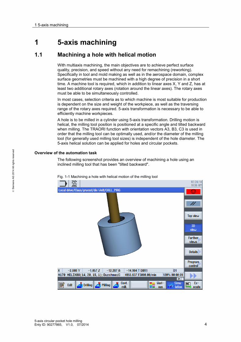
With multiaxis machining, the main objectives are to achieve perfect surfacequality, precision, and speed without any need for remachining (reworking).Specifically in tool and mold making as well as in the aerospace domain, complexsurface geometries must be machined with a high degree of precision in a shorttime. A machine tool is required, which in addition to linear axes X, Y and Z, has atleast two additional rotary axes (rotation around the linear axes). The rotary axesmust be able to be simultaneously controlled.In most cases, selection criteria as to which machine is most suitable for productionis dependent on the size and weight of the workpiece, as well as the traversingrange of the rotary axes required. 5-axis transformation is necessary to be able toefficiently machine workpieces.A hole is to be milled in a cylinder using 5-axis transformation. Drilling motion ishelical, the milling tool position is positioned at a specific angle and tilted backwardwhen milling. The TRAORI function with orientation vectors A3, B3, C3 is used inorder that the milling tool can be optimally used, and/or the diameter of the millingtool (for generally used milling tool sizes) is independent of the hole diameter. The5-axis helical solution can be applied for holes and circular pockets.
Overview of the automation taskThe following screenshot provides an overview of machining a hole using aninclined milling tool that has been "tilted backward".
Fig. 1-1 Machining a hole with helical motion of the milling tool

2 Kinematic transformation
5-axis circular pocket hole millingEnty ID: 90277865, V1.0, 07/2014 5
Siem
ens
AG20
14Al
lrig
hts
rese
rved
2 Kinematic transformationThe kinematic transformation represents a dynamic transformation, where up to 6axes can be simultaneously moved. 5-axis transformation is the most frequentlyused type of transformation.
2.1 5-axis transformation
The task of 5-axis transformation is to compensate movements of the tool nose/tip,which result from changes in orientation while machining. This is realized using theappropriate compensating motion of the geometry axes. The orientation movementis decoupled from the motion of the workpiece contour. This package thus allowsan axially symmetrical tool (milling tool) to be oriented in any desired relation to theworkpiece in every point of the machining space. This is realized using theTRAORI function.At the same time, the traversing motion of the milling tool used is described usingthe mathematical angle function in the "Helix08" subprogram. As a consequence,this ensures helical motion of the milling tool when machining. Combining the twolisted functions (TRAORI and description of the angle functions), represents asimple and efficient solution to machine holes or circular pockets, especially in veryhard materials. For instance, recutting of the milling tool can be eliminated, and asa consequence, also the chatter marks that occurred in the past.
Advantages of the solution presented hereThe solution presented here involving 5-axis transformation offers the followingadvantages: Fast programming at the machine for holes and circular pockets Can be used for very hard materials Chatter marks are avoided, as recutting of the milling tool is not required This results in cost and time savings It can be used on any machine, as the workpiece-related orientation is
independent of the machine kinematics
2.1.1 Precondition
The precondition for 5-axis transformation is a machine tool, which in addition tothree linear axes X, Y and Z, also has two additional rotary axes (rotation aroundthe linear axes), which can be simultaneously controlled. The kinematictransformation requires data about the design of the machine kinematics, which issaved in a machine data.

2 Kinematic transformation
5-axis circular pocket hole millingEnty ID: 90277865, V1.0, 07/2014 6
Siem
ens
AG20
14Al
lrig
hts
rese
rved
2.1.2 Tool orientation
Tool orientation can be specified in two ways:
Machine-related orientationThe machine-related orientation depends on the machine kinematics, and isprogrammed via direct rotary axis positions.
Workpiece-related orientationThe workpiece-related orientation is independent of the machine kinematics and isprogrammed with: Euler angle RPY angle Vector components
The direction of the tool is described in the workpiece coordinate system in thetool-related orientation. This version is used to subsequently implement theapplication. It is possible to program a specific component of the tool in itsorientation to the workpiece. In most cases it is realized using the longitudinal axisof the tool, the tool center point (TCP). TCP programming represents an alternativeterm. Tool motion is always programmed in the right-angled workpiece coordinatesystem.Programmed or set FRAMES rotate and shift this system to the basic system. Toollength correction is taken into account when machining. The kinematictransformation converts this information into motion instructions for the realmachine axes. Programming path and path velocity corresponds to the procedureapplied for 3-axis programming.The tool orientation is additionally programmed in the motion blocks. The real-timetransformation performs the calculation of the resulting motion of all 5 axes. Thegenerated machining programs are therefore not machine-specific.

2 Kinematic transformation
5-axis circular pocket hole millingEnty ID: 90277865, V1.0, 07/2014 7
Siem
ens
AG20
14Al
lrig
hts
rese
rved
2.1.3 Kinematic motion
The swiveling rotary table is the machine kinematics used (Fig. 2-1). Theworkpiece is orientated using two axes in the table (type P). The table can also beused, rotated in the XY plane through 90°.Fig. 2 1 Kinematic solution used
A transformation with the following properties is required in order to be able to takeinto account all of the effects in the NC program: Programming must be independent of the machine kinematics. Automatic tool length correction must be be able to be incorporated. When the tool orientation is changed, compensation is automatically realized.
All of this is implemented using the TRAORI function.
2.2 TRAORI
2.2.1 Tasks of TRAORI
Compensation motion in the X, Y, and Z axes is automatically calculated whenthe tool orientation changes. In so doing, the tool center point (tool tip)maintains its position. As a consequence, CNC programs become morecompact and data management is reduced.
Active tool length and programmable FRAMES, with rotation with respect tothe basic frame, are also included in the calculation. This means that toollength and work offset can be directly changed at the control. This change isimmediately and directly taken into account in the program execution.
The programmed feedrate refers to the tool center point (TCP); as aconsequence, this eliminates the real-time calculation for the rotary axes.
In this case, the real-time transformation performs the calculation of theresulting motion of all 5 axes.

2 Kinematic transformation
5-axis circular pocket hole millingEnty ID: 90277865, V1.0, 07/2014 8
Siem
ens
AG20
14Al
lrig
hts
rese
rved
Advantage The CNC programs generated are independent of any particular machine. This
permits a higher degree of flexibility when machining 5-axis workpieces. In this particular case, kinematic-specific post-processors are not used for
5-axis machining operations with TRAORI.
2.2.2 Example
TRAORI is not used
The controller does not take into account the tool length. It rotates around the axispivot point (1). The tool center point moves out of its position, and therefore doesnot remain fixed in space. Compensation values for tool length from the tool centerpoint to the swivel point must be calculated by the CAM system. As aconsequence, tool length cannot be corrected at the control.Fig. 2-2 Machining a workpiece without TRAORI
Using TRAORIThe control only changes the tool orientation, the position of the tool center pointtherefore remains fixed in space. The compensation motion of the linear axes (2)required is automatically calculated. When TRAORI is active, the controlautomatically compensates the change in the tool length and the work offset.

2 Kinematic transformation
5-axis circular pocket hole millingEnty ID: 90277865, V1.0, 07/2014 9
Siem
ens
AG20
14Al
lrig
hts
rese
rved
Fig. 2-3 Machining a workpiece with TRAORI
2.2.3 Programming 5-axis transformation
CNC programming independent of a machineCNC programming independent of the machine can, when compared to machine-dependent versions, be applied to various machine kinematics. NC programs arealways generated referred to the workpiece. This means that all tool positions arereferred to the workpiece coordinate system (WCS). This involves workpiece-related programming.In order that an NC program can be executed at the machine, the positions mustbe transformed into axis motion, i.e. converted into the machine coordinate system(MCS). The TRAORI function is responsible for this.Generally, TRAORI is called in the CNC program, which is output by the CAMsystem. The CNC program then simply contains: The coordinates of the point to be approached in X, Y, Z The tool orientation with regard to this point in the form of a direction vector
A3=, B3=, C3= or Tool orientation with RPY angle A2=, B2=, C2=
When transformation is activated, the positional data (X, Y, Z) always refers to thetool center point, TCP. Changing the position of the rotary axes involved in thetransformation causes compensating movements of the remaining machine axesso that the position of the tool center point remains unchanged.

2 Kinematic transformation
5-axis circular pocket hole millingEnty ID: 90277865, V1.0, 07/2014 10
Siem
ens
AG20
14Al
lrig
hts
rese
rved
2.2.4 Program syntax
TRAORI(, , , , , ,C).
TRAORI (<n>, <X>, <Y>, <Z>, <A>, <B>, <C>)TRAFOOF
Table 2-1 Syntax of the TRAORI function
NC command Description
TRAORI Activates the 1st programmed 5-axis transformation.TRAORI(, , , , ,,C).
Activates the 5-axis transformation specified under parameter "n".
<n> Number of the 5-axis transformation (n = 1, 2, 3, 4), TRAORIactivates the 1st programmed 5-axis transformation. The number canbe ignored if it involves the first five-axis transformation.
<X>, <Y>, <Z>: Directional normal vector (direction reference) in which the tool tippoints. The components of the directional normal vector are definedusing parameters 2, 3 and 4.If the number of the first 5-axis transformation is not programmed,then instead of the transformation number, a space must be inserted,e.g.TRAORI (,0,1,2), in order to guarantee that parameters arecorrectly identified when specifying a directional normal vector.Direction vector data are absolute, and are not modified by an activeframe.The absolute value of the vector is not decisive, but instead, only thedirection. Non-programmed vector components can be set to zero.
<A>, <B>, <C>: Programmable rotary axis offset.The rotary axis offset is specified in parameters 5, 6 and 7 for thefirst, second and third rotary axis (this depends on the axisconfiguration).When 5-axis transmission is active, an additional offset of the rotaryaxes can be directly programmed here. Preceding parameters do nothave to be specified if the correct sequence was maintained whenprogramming, e.g. TRAORI(, , , ,A,B,C) – or if an offset is onlyrequired for one rotary axis, for exampleTRAORI(, , , , , ,C).As an alternative to the rotary axis offset, the programmable rotaryaxis offset can be used in the work offset that can be saved, and isadded to the active work offset for the rotary axes involved in thetransformation. Accepting data from the work offset is configuredusing MD24590 $MC_TRAFO5_ROT_OFFSET_FROM_FR_1.
TRAFOOF Deactivates all transformations.

2 Kinematic transformation
5-axis circular pocket hole millingEnty ID: 90277865, V1.0, 07/2014 11
Siem
ens
AG20
14Al
lrig
hts
rese
rved
Directional normal vector for the reference of the tool center pointTRAORI (1,0,0,1) – activates the first 5-axis transformation, with a
Directional normal vector of the tool center point in the Z axisTRAORI (1,0,1,0) – activates the first 5-axis transformation, with a
vector normal to the direction of the tool center point in the Y axisTRAORI (1,1,0,0) – activates the first 5-axis transformation, with a
vector normal to the direction of the tool center point in the X axisTRAORI (2,0,1,1) – activates the second 5-axis transformation, with a
Direction vector
Note The directional normal vector of the tool center point does not lead to anychange in the tool orientation itself, but only represents the direction reference ofthe tool center point.
2.3 Tool orientation
2.3.1 Programming linear and rotary axes
To accommodate machining scenarios involving tools set at an angle or in order tomill geometries located anywhere in space, the three linear axes X, Y and Z arerequired along with two of the rotary axes A, B or C. The axes must be able to besimultaneously controlled. The tool position is approached in space using linearaxes X, Y and Z. This enables the tool center point to adopt any position. For 3-axis machining by programming the three linear axes. The contour is milled line byline by moving the 3 linear axes.Rotary axes will also be required if the tool also has to be set at an angle. Usingthree linear axes and two rotary axes, theoretically any point in space can beapproached with any tool orientation.

2 Kinematic transformation
5-axis circular pocket hole millingEnty ID: 90277865, V1.0, 07/2014 12
Siem
ens
AG20
14Al
lrig
hts
rese
rved
2.3.2 Programming directions vectors
The components of direction vector 1 are programmed with addresses A3, B3, andC3. The vector points in the direction of the toolholder. The vector length is of nosignificance. Non-programmed vector components are set to zero.Fig. 2-4 Programming a direction vector
Table 2-2 Syntax of the direction vectors
NC commands Direction vector
G1 X.. Y.. Z.. A3=.. B3=.. C3=.. Programming direction vectors
In the example (Fig. 2-4), the tool is at position (X0, Y0, Z0) as diagonal of a cubeof 35.26° in the resulting XY plane.
N10 TRAORIN20 G54 D1N30 G1 X0 Y0 Z0 A3=1 B3=1 C3=2 F1000….

3 Helical cycle for roughing
5-axis circular pocket hole millingEnty ID: 90277865, V1.0, 07/2014 13
Siem
ens
AG20
14Al
lrig
hts
rese
rved
3 Helical cycle for roughing3.1.1 Overview
The cycle subsequently presented is used to machine holes or circular pocket. Ahole is machined in the cylindrical unmachined part (blank); the milling tool usedperforms helical motion. The milling tool moves at an angle and "tilted backward"while the program is being executed. The cycle comprises a main program and subprogram. The TRAORI and cycle 832 functions, already explained in Chapter 2,are used in the main program of the cycle. The complete helical motion of themilling tool is the content of the Helix08 subprogram.
3.1.2 Angle functions
The helical motion of the milling tool can be explained using trigonometric functionsin right-angled triangles. The sinusoidal and/or cosinusoidal function is defined asfollows.
Figure 3 1 Definition of angle functions
cos = (3.1)
sin = (3.2)
The X coordinate can be expressed using equation (3.1) as follows using thisexample.
cos = x (3.3)

3 Helical cycle for roughing
5-axis circular pocket hole millingEnty ID: 90277865, V1.0, 07/2014 14
Siem
ens
AG20
14Al
lrig
hts
rese
rved
Equation (3.4) is obtained for the value of the X coordinate in subprogram Helix08(N190).
X = _APOSX + cos _ (3.4)
This is displayed as follows in the Helix08 program.
N190 G1 X=_APOSX+COS(0)*_DURCH Y=_APOSY+SIN(0)*_DURCH
Table 3-1 Helical cycle commands used
Commands used Significance
_APOSX Actual value of the milling tool in the WCS Cos = 0°
_DURCH Specifies the radius of the hole in, as_DURCH=_DURCH/2
The Y coordinate is calculated analogously using a sinusoidal function.
3.1.3 Setting the angle and vectors
The radius of the active tool must be defined, as otherwise it is possible that themilling tool would exceed its tolerances and violate the contour. Direction vectorsA3/B3/C3 are specified as follows. As the milling tool makes a type of helicalmotion, when specifying the circular motion, the opposite side must also be takeninto account. This is the reason that 180° must be used, as otherwise only asemicircular machining operation will be performed. A second aspect is the factthat the milling tool is tilted backward. As a result, there is the risk that the edge ofthe unmachined part will be violated by the milling tool when it performs its helicalmotion. A correction factor TAN_SCHRAE is introduced to prevent this happening.C3 actually corresponds to the cosinusoidal value of the angled position of themilling tool. This value was rounded off and set to a value of 1.
N150 TRAORIN160 _DURCH=_DURCH/2-$P_TOOLR;N170 _KPOSZ=_KPOSZ+sin(_SCHRAE)*$P_TOOLRN170 _KPOSZ=_KPOSZ+sin(_SCHRAE)*$P_TOOLRN190 G1 X=_APOSX+COS(0)*_DURCH Y=_APOSY+SIN(0)*_DURCHN200 G0 Z=_KPOSZ A3=(COS(_WINK+180-_VORWI)*TAN(_SCHRAE))B3=(SIN(_WINK+180-_VORWI)*TAN(_SCHRAE)) C3=1

3 Helical cycle for roughing
5-axis circular pocket hole millingEnty ID: 90277865, V1.0, 07/2014 15
Siem
ens
AG20
14Al
lrig
hts
rese
rved
Figure 3-2 running helix cycle
3.1.4 Breaking down into increments
Mark 1 checks the condition of the helical motion. The circle is split up into identicalincrements after splitting up the circle of the helical motion into angular segments.This checks as to whether, when executing the program, the actual milling toolposition coincides with the required final position. The program has beencompleted once this condition has been fulfilled.
N210 MARK1: N220 _WINK=_WINK+(360/(6.28*_DURCH*2)) N230 _KPOSZ=_KPOSZ-(_STEP/(360/(360/(6.28*_DURCH*2)))) N240 IF _KPOSZ<_KENDZ N250 _KPOSZ=_KENDZ

4 NC programs used
5-axis circular pocket hole millingEnty ID: 90277865, V1.0, 07/2014 16
Siem
ens
AG20
14Al
lrig
hts
rese
rved
4 NC programs used4.1 Main program 5-axis circular pocket hole milling
G17 G90 G64 G54 G71 ; Starting point
WORKPIECE(,"C",,"CYLINDER",0,0,-50,-80,60) ; Workpiece definition
T="D8R1" M6 ; Tool call and change
S8000 M3 ; Technology dataD1TOFFL=0CYCLE832(0.05,_ORI_ROUGH,1) ;Tolerance value 0.05 mm,
"roughing", multiaxis machiningF2000TRAFOOF Deactivate ;5-axis transformation
N100 G0 A0 C0N110 G0 Z100 ; RetractN120 G0 X0 Y0
N130 TRAORI ; Activate 5-axis transformation
N140 G0 X0 Y0 A3=0 B3=0 C3=1 Align tool parallel to the Z axisFGROUP(C) ; Starting point
FGREF[C]=21 ; Feedrate calculation Axis orientation
N150 G1 Z0 F3000 ; Selecting the feedrate
N170 HELIX08(26,20,15,1); Diameter, depth, angular position, infeed per revolution
N190 M30 ; End of program
4 NC programs used
5-axis circular pocket hole millingEnty ID: 90277865, V1.0, 07/2014 17
Siem
ens
AG20
14Al
lrig
hts
rese
rved
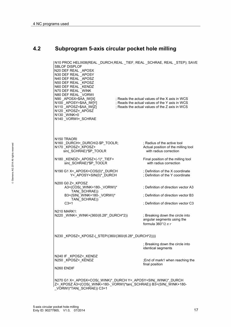
4.2 Subprogram 5-axis circular pocket hole milling
N10 PROC HELIX08(REAL _DURCH,REAL _TIEF, REAL _SCHRAE, REAL _STEP); SAVE SBLOF DISPLOF
N20 DEF REAL _APOSX N30 DEF REAL _APOSY N40 DEF REAL _APOSZ N50 DEF REAL _KPOSZ N60 DEF REAL _KENDZ N70 DEF REAL _WINK N80 DEF REAL _VORWI N90 _APOSX=$AA_IW[X] ; Reads the actual values of the X axis in WCS N100 _APOSY=$AA_IW[Y] ; Reads the actual values of the Y axis in WCS N110 _APOSZ=$AA_IW[Z] ; Reads the actual values of the Z axis in WCS N120 _KPOSZ=_APOSZ N130 _WINK=0 N140 _VORWI=_SCHRAE
N150 TRAORI N160 _DURCH=_DURCH/2-$P_TOOLR; ; Radius of the active tool N170 _KPOSZ=_KPOSZ+ Actual position of the milling tool sin(_SCHRAE)*$P_TOOLR with radius correction
N180 _KENDZ=_APOSZ+(-1)*_TIEF+ Final position of the milling tool sin(_SCHRAE)*$P_TOOLR with radius correction
N190 G1 X=_APOSX+COS(0)*_DURCH ; Definition of the X coordinate Y=_APOSY+SIN(0)*_DURCH ; Definition of the Y coordinate
N200 G0 Z=_KPOSZ A3=(COS(_WINK+180-_VORWI)* ; Definition of direction vector A3 TAN(_SCHRAE))
B3=(SIN(_WINK+180-_VORWI)* ; Definition of direction vector B3 TAN(_SCHRAE)) C3=1 ; Definition of direction vector C3
N210 MARK1: N220 _WINK=_WINK+(360/(6.28*_DURCH*2)) ; Breaking down the circle into
angular segments using theformula 360°/2
N230 _KPOSZ=_KPOSZ-(_STEP/(360/(360/(6.28*_DURCH*2))))
; Breaking down the circle intoidentical segments
N240 IF _KPOSZ<_KENDZ N250 _KPOSZ=_KENDZ ;End of mark1 when reaching the
final position N260 ENDIF
N270 G1 X=_APOSX+COS(_WINK)*_DURCH Y=_APOSY+SIN(_WINK)*_DURCH Z=_KPOSZ A3=(COS(_WINK+180-_VORWI)*tan(_SCHRAE)) B3=(SIN(_WINK+180- _VORWI)*TAN(_SCHRAE)) C3=1

4 NC programs used
5-axis circular pocket hole millingEnty ID: 90277865, V1.0, 07/2014 18
Siem
ens
AG20
14Al
lrig
hts
rese
rved
N280 IF (_WINK+(360/(6.28*_DURCH*2)))<360 ; Condition to repeat the mark N290 GOTOB MARK1 N300 ENDIF
N310 IF _KPOSZ>(_KENDZ) ; Condition to repeat the mark N320 _WINK=0 N330 GOTOB MARK1 N340 ENDIF
N350 SPRUNG: N360 _WINK=_WINK+(360/(6.28*_DURCH*2)) N370; MSG("STEP= "<<(360/(6.28*_DURCH*2))) N380 G1 X=_APOSX+COS(_WINK)*_DURCH Y=_APOSY+SIN(_WINK)*_DURCH Z=_KENDZ A3=(COS(_WINK+180-_VORWI)*tan(_SCHRAE)) B3=(SIN(_WINK+180- _VORWI)*TAN(_SCHRAE)) C3=1 N390 IF (_WINK)<360 ; Condition to repeat the jump N400 GOTOB SPRUNG N410 ENDIF
N420 G1 Z=_APOSZ N430 G1 X=_APOSX Y=_APOSY A3=0 B3=0 C3=1 ; Align tool parallel to the Z axis N440 M17 End of program

5 Contact person
5-axis circular pocket hole millingEnty ID: 90277865, V1.0, 07/2014 19
Siem
ens
AG20
14Al
lrig
hts
rese
rved
5 Contact personSiemens AGIndustry SectorI DT MC MTS APCFrauenauracher Straße 80D - 91056 Erlangenmailto: [email protected]
6 History
Table 6 1
Version Date Revision
V1.0 07/2014 First Edition