APPENDIX VIA – External ViaSat Modem 1 Introduction · 2019-08-15 · RC4000 Antenna Controller...
13
RC4000 Antenna Controller Appendix VIA External ViaSat Modem VIA-1 APPENDIX VIA – External ViaSat Modem Last Revised: 21 August 2015 This appendix describes the additional functions provided by the RC4000's external ViaSat modem option. 1 Introduction 1.1 Manual Organization This appendix is provided as a supplement to the baseline RC4000 manual. The corresponding paragraphs in the baseline RC4000 manual are referred to when data specific to the external ViaSat modem option is described. 1.2 RC4000 Features This option provides the ability to automatically connect to the ViaSat network via an external ViaSat Surfbeam 2 modem. 1.3 Software Overview RC4000 software configuration is presented in the form RC4K-ab-vwxyz where ab-vwxyz represents: (Mount manufacturer/Model) ab (Navigation Sensor Option) v (Tracking Option) w (Remote Option) x (Internal Receiver Option) y (External Receiver Option) z Software that has support for the ViaSat Surfbeam 2 software will have a V in the External Receiver Option position.
Transcript of APPENDIX VIA – External ViaSat Modem 1 Introduction · 2019-08-15 · RC4000 Antenna Controller...
RC4000 Antenna Controller Appendix VIA External ViaSat Modem
VIA-1
APPENDIX VIA – External ViaSat Modem Last Revised: 21 August 2015 This appendix describes the additional functions provided by the RC4000's external ViaSat modem option.
1 Introduction
1.1 Manual Organization This appendix is provided as a supplement to the baseline RC4000 manual. The corresponding paragraphs in the baseline RC4000 manual are referred to when data specific to the external ViaSat modem option is described.
1.2 RC4000 Features This option provides the ability to automatically connect to the ViaSat network via an external ViaSat Surfbeam 2 modem.
1.3 Software Overview RC4000 software configuration is presented in the form RC4K-ab-vwxyz where ab-vwxyz represents: (Mount manufacturer/Model) ab (Navigation Sensor Option) v (Tracking Option) w (Remote Option) x (Internal Receiver Option) y (External Receiver Option) z Software that has support for the ViaSat Surfbeam 2 software will have a V in the External Receiver Option position.

RC4000 Antenna Controller Appendix VIA External ViaSat Modem
VIA-2
1.4 Specifications In addition to the hardware specifications of the controller as found in the baseline manual, the specifications of the ViaSat Surfbeam 2 modem and Tria can be found in the following figure.

RC4000 Antenna Controller Appendix VIA External ViaSat Modem
VIA-3
2 Hardware
2.1 Boardset Devices
2.1.2 Electrical Interfaces
2.1.2.4 Options Board
2.1.2.4.1 J9 – Ethernet In addition to the information described in the RC4000 baseline manual, the following image shows a diagram for how the ViaSat Surfbeam 2 modem would connect to the Ethernet port on the RC4000 boardset.

RC4000 Antenna Controller Appendix VIA External ViaSat Modem
VIA-4
2.1.2.4.2 J14 – IP Reset As stated in the baseline RC4000 manual, when an IP reset is performed, the IP address will be reset to 192.168.1.1. The gateway on the RC4000 will also be reset. After a IP reset, please ensure that the IP address is set to 192.168.1.50 and the gateway is set to 192.168.1.10.
2.2 External Equipment
2.2.9 Chassis ViaSat Connections The RC4000 can also be installed in a variety of chassis configurations that would include external ports. The modem will interface via a standard Ethernet cable to the Ethernet port on the chassis of the controller. Consult your enclosure specific appendix (Appendix C) for guidance on which port will be used for Ethernet. For reference, the following image shows a diagram for how the ViaSat Surfbeam 2 modem would connect to the Ethernet port on the RC4000 controller in a chassis.

RC4000 Antenna Controller Appendix VIA External ViaSat Modem
VIA-5
3 Software
3.2 Operating Group
3.2.1 Manual Mode In the baseline RC4000 manual it lists SS1, SS2, and RF as possible signal strength options that can be displayed. Software that has the ViaSat option will have VIA signal strength, indicating a signal strength being provided via Ethernet. The signal strength will be 0 when the controller is communicating with the modem, but is not receiving any signal from the satellite. If the controller is not communicating with the modem the signal strength will display ****. When the controller is communicating with the modem and the modem is on the satellite the signal strength will be displayed as an integer greater than 0. The signal strength will correspond to the receive power being reported by the modem (i.e. 1200 = 12.0 dBm).
3.2.2 Menu Mode
3.2.2.3 Locate Note: When the modem enters the network after satellite acquisition, the controller will momentarily lose communication with the modem and display a signal strength of ****. This is normal operation and is expected. In addition to the LOCATE functions described in the RC4000 baseline manual, software with the ViaSat modem option will have an initial step in the locate process. When using the ViaSat software, the modem will tell the controller what satellite to locate. When this occurs you will see the following screen.
LOCATE VIASAT: WAITING FOR SATELLITE... <MODE>EXIT
The modem will then provide the correct satellite for the current location of the antenna. Please note that this may change based on data from ViaSat, but the modem will always provide the correct satellite. Once the satellite information has been provided the following screen will appear.
POS: 38°56N 94°44W 180.0 LOCATE SAT:115.0W 115.0W AZ: 30.1 EL: 40.2 <1>SELECT NEW SAT READY TO LOCATE
Note that if the ViaSat Tria is the only feed installed on your antenna, the SELECT NEW SAT option should not be used. In this case the satellite from the ViaSat modem should always be used.
3.2.2.3.1 Satellite Selection On antennas that have only the ViaSat Tria as a feed, this option should not be used.

RC4000 Antenna Controller Appendix VIA External ViaSat Modem
VIA-6
3.2.2.3.2 LOCATE Automatic Movement Note: When the modem enters the network after satellite acquisition, the controller will momentarily lose communication with the modem and display a signal strength of ****. This is normal operation and is expected. In the baseline RC4000 manual the option to choose the polarization prior to a LOCATE is discussed. For controllers with the ViaSat software option, this step will be skipped and the movement to the start of the scan will begin.
3.2.2.4 Store This option is not available on the ViaSat modem software.
3.2.2.5 Recall This option is not available on the ViaSat modem software.
3.2.2.6 Delete This option is not available on the ViaSat modem software.
3.2.2.8 Settings In addition to what is discussed in the RC4000 baseline manual, the ViaSat modem will have VIA as a locate source. This will be selected by default and should not be changed on antennas that have only the ViaSat Tria as a feed option.
3.3 Programming Group
3.3.1 Configuration Mode
3.3.1.1 Normal Access Items
3.3.1.1.3 Preset Satellites When using a ViaSat modem as a locate source, the preset satellite list will not be used. Instead the modem will provide the appropriate information to the controller.
3.3.1.2 Installation Access Items
3.3.1.2.8 Autopeak In addition to the items described in the RC4000 baseline manual, the ViaSat software option will allow for the selection of VIA as a locate source. This option will be selected by default and should not need to be changed.

RC4000 Antenna Controller Appendix VIA External ViaSat Modem
VIA-7
3.3.1.2.9 ViaSat Sig Factors This screen will only be available on controllers with the ViaSat software option and covers the configuration items for the ViaSat modem.
CONFIG-VIA THRES: 100 TIME:1.0 SCAN RG: 30 SRCH AZ: 3 SRCH EL: 3 MINIMUM SIGNAL THRESHOLD <0-4095>
THRES: MINIMUM SIGNAL THRESHOLD <0-4095> The threshold item defines what the minimum signal strength indication from the ViaSat modem is required for the LOCATE system to “recognize” that a satellite is present. TIME: LOCK TIME <0.1 – 9.9> SECONDS This item defines how long the RC4000 will wait after each step before sampling signal strength. Increasing this value may be required to allow the ViaSat modem to provide a signal strength output. SCAN RG: SCAN RANGE <1-30 DEGREES> This item defines how many degrees to either side of the nominal azimuth target the controller will scan during the LOCATE operation. SRCH AZ: SPIRAL SEARCH AZIM LIMIT <1 – 20 DEGREES> SRCH EL: SPIRAL SEARCH ELEV LIMIT <1 – 15 DEGREES> These items would only be used for ViaSat satellites that are in inclined orbits. Currently there are no inclined orbit ViaSat satellites and this option is not supported.

RC4000 Antenna Controller Appendix VIA External ViaSat Modem
VIA-8
4 Support
4.2 Troubleshooting
4.2.7 ViaSat This troubleshooting section is in addition to what is listed in the RC4000 baseline manual and is specific to the ViaSat modem software.
• Unable to connect to the RC4000 Antenna Controller from PC o Verify the following on the RC4000
RC4000 is powered on RC4000 is connected via Ethernet cable to a LAN port on the router Static IP address set to 192.168.1.50 Netmask set to 255.255.255.0 Gateway set to 192.168.1.10
o Verify the following on the router Router is powered on Static IP address set to 192.168.1.10 Netmask set to 255.255.255.0
o Verify the following on the PC Computer is powered on Computer is connected via Ethernet cable to a LAN port on the router Computer is setup to obtain IP automatically from the router Computer is setup to obtain DNS automatically from the router
• Unable to connect to ViaSat modem from PC
o Verify the following on the modem Modem is powered on Modem is connected via Ethernet cable to the WAN port on the router Static IP address is set to 192.168.100.1 Netmask set to 255.255.255.0
o Verify the following on the router Static IP address set to 192.168.1.10 Netmask set to 255.255.255.0 LAN setup as DHCP server WAN setup as DHCP from ViaSat Modem
• No communication between ViaSat modem and RC4000 Antenna Controller
o Verify the following on the RC4000 RC4000 is powered on RC4000 is connected via Ethernet cable to a LAN port on the router Static IP address set to 192.168.1.50 Netmask set to 255.255.255.0 Gateway set to 192.168.1.10
o Verify the following on the router Router is powered on Static IP address set to 192.168.1.10 Netmask set to 255.255.255.0
o Verify the following on the modem Modem is powered on Modem is connected via Ethernet cable to the WAN port on the router Static IP address is set to 192.168.100.1 Netmask set to 255.255.255.0

RC4000 Antenna Controller Appendix VIA External ViaSat Modem
VIA-9
• RC4000 Antenna Controller finds satellite but PC does not internet access o Verify the following on the router
LAN setup as DHCP server WAN setup as DHCP from ViaSat Modem DNS Relaying is turned on

RC4000 Antenna Controller Appendix VIA External ViaSat Modem
VIA-10
5 Hardware Setup This section covers how the various pieces of hardware should be setup to make the setup work as expected.
5.1 Computer Setup
5.1.1 Computer Hardware The computer being used for this is running Windows 7 and is connected to LAN port 1 on the router.
5.1.2 Computer IP Settings The following steps will configure the IP correctly on Windows 7 to work with the ViaSat modem setup.
1. From the start menu go to Control Panel. 2. Navigate to the Network and Sharing Center.
3. Click on the Local Area Connection shown by the red arrow in the above image. 4. In the dialog box that opens click on the properties button. 5. Highlight the Internet Protocol Version 4 (TCP/IPv4) and then click the properties button. 6. In the dialog box that opens, click the Obtain IP address automatically button and the obtain DNS
server address automatically button. 7. Press OK and close out all windows that were opened for this process.
The computer is now configured properly for the ViaSat modem setup.

RC4000 Antenna Controller Appendix VIA External ViaSat Modem
VIA-11
5.2 Router Setup
5.2.1 Router Hardware For our setup we were using a TRENDnet TW100-SW41CA router with software version 2.3.30.
5.2.2 Router Static IP Setup
1. With the computer connected to LAN port 1 on the router and the router powered on, navigate to 192.168.10.1 via a web browser.
2. The default username (admin) and password (admin) will both be needed to log into the router and then select Advanced Setup.
3. On the left side of the screen select LAN and then LAN Settings.
4. The IP Address of the Router should then be changed to 192.168.1.10. 5. Once the router reboots navigate to 192.168.1.10 via a web browser to verify the IP address has
correctly changed.
5.2.3 DHCP LAN Server Setup
1. Log into the router using the default username and password and then select Advanced Setup. 2. On the left side of the screen select LAN and the LAN Settings. 3. Make sure the check box next to The Gateway acts as DHCP Server box is checked to enable
the router as a DHCP LAN server. 4. The IP Pool Starting Address should be set to 192.168.10.51 and then the settings applied and
the router will reboot.
5.2.4 DHCP WAN Setup
1. Log into the router using the default username and password and then select Advanced Setup. 2. Verify that the Dynamic IP option is selected.
The router is now configured properly to work with the ViaSat modem setup.

RC4000 Antenna Controller Appendix VIA External ViaSat Modem
VIA-12
5.3 Controller Setup
5.3.1 Controller Hardware The controller must have the ViaSat Software as described in section 1.3 in this appendix. The controller will also need to be connected to LAN port 2 on the router with the computer still connected into LAN port 1.
5.3.2 Controller IP Settings
1. Using the web browser on the computer navigate to 192.168.1.1/config. 2. Click on the system settings page and in the corresponding panel set the following:
• ACU Settings o IP Address: 192.168.1.50 o Subnet Mask: 255.255.255.0 o Gateway: 192.168.1.10
• ViaSat Settings o IP Address: 192.168.100.1
3. Click the save button and the web browser will redirect to the system configuration page at 192.168.1.50/config
The controller is now configured properly to work with the ViaSat modem setup.
5.4 Modem Setup
5.4.1 Modem Hardware This setup was tested using a ViaSat Surfbeam 2 modem. The hardware version is UT_11 KATT_V1 and the software version is UT_2.2.0.2.0. The modem will need to be connected to the WAN port on the router.
5.4.2 Modem IP Settings The IP address on the ViaSat modem is factory set to 192.168.100.1 and cannot be changed.
RC4000 Antenna Controller Appendix VIA External ViaSat Modem
VIA-13
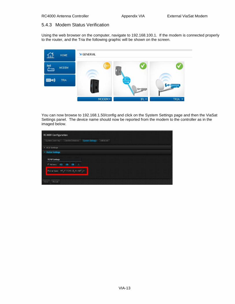
5.4.3 Modem Status Verification Using the web browser on the computer, navigate to 192.168.100.1. If the modem is connected properly to the router, and the Tria the following graphic will be shown on the screen.
You can now browse to 192.168.1.50/config and click on the System Settings page and then the ViaSat Settings panel. The device name should now be reported from the modem to the controller as in the imaged below.