APPENDIX E STORMWATER TREATMENT FACILITY … · Stormwater Treatment Facility Components 14-E-5 •...
44
Stormwater Treatment Facility Components 14-E-1 APPENDIX E STORMWATER TREATMENT FACILITY COMPONENTS 1.0 Introduction This appendix provides information for the design of stormwater treatment facility components. Facility components are the features that when combined with the treatment facility design assist with treatment, conveyance, erosion countermeasures, and energy dissipation. Facility components mentioned in this appendix include: • Water Quality Mix – Section 2 • Inlet Structures – Section 3 • Pretreatment Facilities or Structures – Section 4 • Flow Spreading Options – Section 5 • Outlet Control Structures – Section 6 • Auxiliary Outlets – Section 7 • Storm Drain Piping – Section 8 • Outfalls – Section 9 Facility components are designed after a BMP is selected and sized from guidance provided in this chapter or other method approved through the hydraulic design deviation process. 2.0 Water Quality Mix The goal is to create a soil “Water Quality Mix”, that meets criteria for organic content, infiltration rate (long-term hydraulic conductivity), and other soil characteristics described below, by combining soil amendments (such as compost) along with the appropriate in-situ, stockpiled or imported soil. Soil amendments include inorganic materials and organic matter that helps restore the fertility and condition of the soil, supports infiltration and improves pollutant removal capabilities. Soil organic matter can be increased by adding materials such as compost, composted woody material, biosolids, and forest product residuals. Soil amendment is used to enhance the efficiency of filter strips (dispersion areas), biofiltration swales, bioretention facilities, and extended dry detention facilities. In those facilities, it assists in the retention of stormwater to allow for infiltration down into the underlying soil, as well as providing treatment before the stormwater enters the groundwater or conveyance system. April 2014 ODOT Hydraulics Manual
Transcript of APPENDIX E STORMWATER TREATMENT FACILITY … · Stormwater Treatment Facility Components 14-E-5 •...
Stormwater Treatment Facility Components 14-E-1
APPENDIX E STORMWATER TREATMENT FACILITY COMPONENTS
1.0 Introduction
This appendix provides information for the design of stormwater treatment facility components. Facility components are the features that when combined with the treatment facility design assist with treatment, conveyance, erosion countermeasures, and energy dissipation. Facility components mentioned in this appendix include: • Water Quality Mix – Section 2 • Inlet Structures – Section 3 • Pretreatment Facilities or Structures – Section 4 • Flow Spreading Options – Section 5 • Outlet Control Structures – Section 6 • Auxiliary Outlets – Section 7 • Storm Drain Piping – Section 8 • Outfalls – Section 9 Facility components are designed after a BMP is selected and sized from guidance provided in this chapter or other method approved through the hydraulic design deviation process. 2.0 Water Quality Mix The goal is to create a soil “Water Quality Mix”, that meets criteria for organic content, infiltration rate (long-term hydraulic conductivity), and other soil characteristics described below, by combining soil amendments (such as compost) along with the appropriate in-situ, stockpiled or imported soil. Soil amendments include inorganic materials and organic matter that helps restore the fertility and condition of the soil, supports infiltration and improves pollutant removal capabilities. Soil organic matter can be increased by adding materials such as compost, composted woody material, biosolids, and forest product residuals. Soil amendment is used to enhance the efficiency of filter strips (dispersion areas), biofiltration swales, bioretention facilities, and extended dry detention facilities. In those facilities, it assists in the retention of stormwater to allow for infiltration down into the underlying soil, as well as providing treatment before the stormwater enters the groundwater or conveyance system.
April 2014 ODOT Hydraulics Manual
14-E-2 Stormwater Treatment Facility Components
Applications
• Can be incorporated into native or imported soils to improve infiltration, retention capacity and pollutant removal capability
• Can be used in most locations where highway runoff will flow over or be detained on soil and vegetated ground.
• Is a standard component in new facilities such as swales, filter strips, detention and retention ponds, and roadside ditches to enhance pollutant removal and promote infiltration.
• Can be installed in existing facilities such as swales, filter strips, detention and retention ponds, and roadside ditches to enhance pollutant removal and promote infiltration.
Mixing or Blending Methods
There are three methods to achieve a water quality mix:
1. on-site soils are suitable 2. on-site soils can be amended in-place, or 3. special materials must be imported
More than one method can be used on different portions of the same site. The method selected must be based upon laboratory testing and analysis of the existing soil, imported soil, and organic soil amendment. Method 1: Soil Amendment is not necessary if the surface native soil meets the following properties. This guidance is for providing water quality treatment outside of groundwater protection areas. Determine any special requirements for groundwater protection areas and wellhead protection zones. Applicable for filter strips, planting beds, dispersion areas, and swales:
• Organic matter content (dry weight) – 8% to 10% for planting beds and landscaped areas; 5% or greater for filter strips, dispersion areas, swales, or area supporting foot traffic during wet months (per ASTM Designation D 2974).
• The existing soil meets the gradation requirements in Method 3. Applicable for cells and ponds:
• Organic matter content (dry weight) – 5% or greater for cells and ponds (per ASTM Designation D 2974).
• The design or long term infiltration rate of 9 inches per hour or less outside of
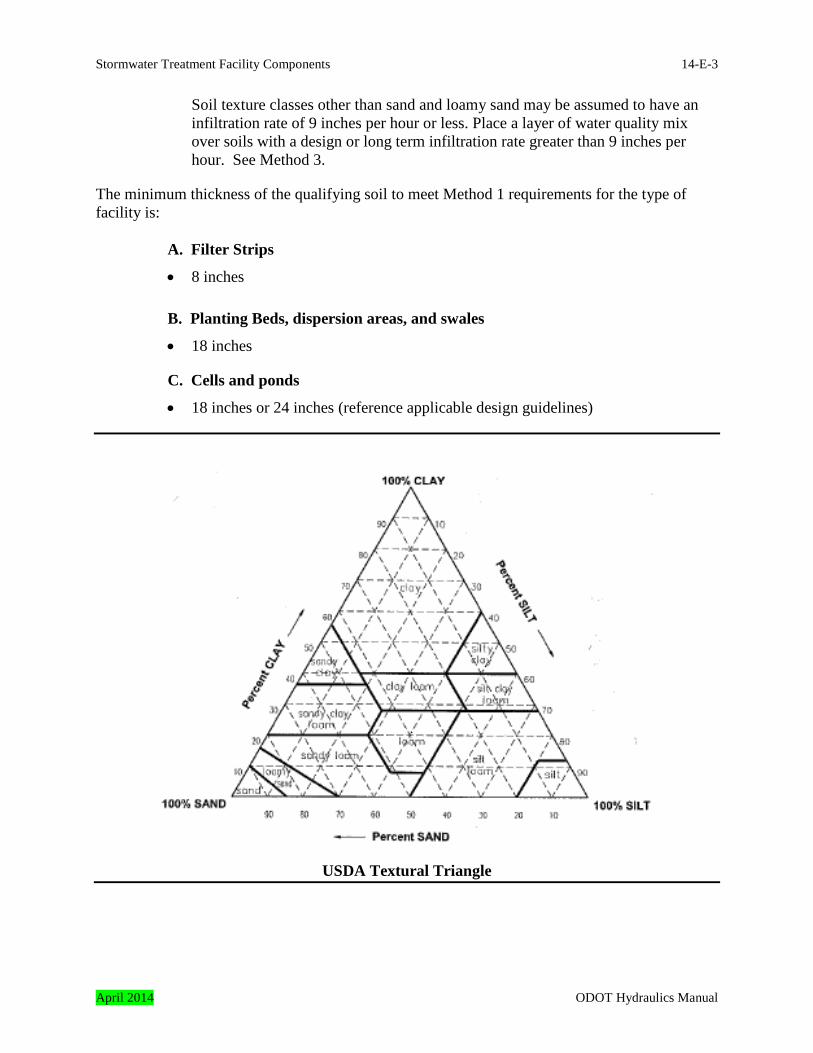
groundwater protection areas or the soil is logged as one of the classes from the USDA Textural Triangle provided below excluding sand, loamy sand, and clay.
ODOT Hydraulics Manual April 2014
Stormwater Treatment Facility Components 14-E-3
Soil texture classes other than sand and loamy sand may be assumed to have an infiltration rate of 9 inches per hour or less. Place a layer of water quality mix over soils with a design or long term infiltration rate greater than 9 inches per hour. See Method 3.
The minimum thickness of the qualifying soil to meet Method 1 requirements for the type of facility is:
A. Filter Strips
• 8 inches
B. Planting Beds, dispersion areas, and swales
• 18 inches
C. Cells and ponds
• 18 inches or 24 inches (reference applicable design guidelines)
USDA Textural Triangle
April 2014 ODOT Hydraulics Manual
14-E-4 Stormwater Treatment Facility Components
Method 2: Soil amendement is necessary when the existing soil meets the criteria noted in Method 1 but the organic matter content does not meet the following requirement:
• Organic matter content (dry weight) – 8% to 10% for planting beds and landscaped areas; 5% or greater for filter strips, dispersion areas, swales, cells, ponds or area supporting foot traffic during wet months (per ASTM Designation D 2974).
Increase the organic matter content by amending the soil as noted below. Scarify or till to a 12 inch depth. Entire surface should be disturbed by scarification, except do not scarify within drip line of existing trees that will be retained. Coordinate this work with the project roadside Development designer.
A. Filter Strips
• DEFAULT RATE: Place 2-inches of composted material (see water quality mix section below) and roto-till into 6 inches of soil
• CALCULATED RATE: Place calculated amount of composted material or approved organic material and roto-till into depth of soil needed to achieve 8 inches of settled soil at 5% or greater organic content.
Use a manually operated landscape water filled roller to compact soil. Rake to level, and remove surface woody debris and rocks larger than 1 inch diameter. In arid climates a cover of larger rocks is acceptable if needed to prevent erosion of the amended soil.
B. Planting Beds
• DEFAULT RATE: Place 6-inches of composted material and roto-till into 12 inches of soil (total 18 inches of amended soil)
• CALCULATED RATE: Place calculated amount of composted material or approved organic material and roto-till into depth of soil needed to achieve 18 inches of settled soil at 8-10 percent organic content.
Rake beds to smooth and remove surface rocks larger than 2 inches diameter. Mulch planting beds with 2 inches of organic mulch.
C. Dispersion Areas, Swales, Cells, and Ponds
• DEFAULT RATE: Place 4-inches of composted material and rototill into 14 inches of soil (total 18 inches of amended soil.) for dispersion areas and swales. Place 5-inches of compost material and rototill into 19 inches of soil (total 24 inches of amended soil.) for cells and ponds.
ODOT Hydraulics Manual April 2014
Stormwater Treatment Facility Components 14-E-5
• CALCULATED RATE: Place calculated amount of composted material or approved organic material and rototill into depth of soil needed to achieve 18 or 24 inches of settled soil at 5% or greater organic content.
Use a manually operated landscape water filled roller to compact soil. Rake to level, and remove surface woody debris and rocks larger than 1 inch diameter. In arid climates a cover of larger rocks is acceptable if needed to prevent erosion of the amended soil.
Method 3: Existing soil does not meet the requirements noted in Method 1. Place or excavate and replace with the water quality mix appropriate for the specific application. Scarify or till to a 12-inch depth. Entire surface should be disturbed by scarification, except do not scarify within drip line of existing trees to be retained.
A. Filter Strips
• Use imported or stockpiled Mix containing 20%-25% compost with 75%-80% water quality soil media.
• Place 8 inches of Mix.
Use a manually operated landscape water filled roller to compact soil. Rake to level, and remove surface rocks larger than 1-inch diameter. In arid climates a cover of larger rocks is acceptable if needed to prevent erosion of the amended soil.
B. Planting Beds
• Use imported or stockpiled Mix containing 30%-35% compost with 65%-70% water quality soil media.
• Place 18 inches of Mix.
Rake beds to level, and remove surface rocks and woody debris over 1 inch diameter. Mulch planting beds with 2 inches of organic mulch.
C. Dispersion Areas, Swales, Cells, and Ponds
• Use imported or stockpiled Mix containing 20%-25% compost with 75%-80% water quality soil media.
• Place 24 inches of Mix in ponds or cells otherwise use 18 inches.
Use a manually operated landscape water filled roller to compact soil. Rake to level, and remove surface rocks larger than 1-inch diameter. In arid climates a cover of larger rocks is acceptable if needed to prevent erosion of the amended soil.
April 2014 ODOT Hydraulics Manual

14-E-6 Stormwater Treatment Facility Components
Water Quality Mix Soil Properties 1. The existing, stockpiled or imported soil must meet the following gradation requirements:
Sieve Size
Percent Passing (By Weight)
No. 4 100 No. 10 95 – 100 No. 40 40 – 60 No. 100 10 – 25 No. 200 5 – 10
Water Quality Soil Media
• Sampling must meet the requirements of AASHTO T2. • Sieve analysis must meet the requirements of AASHTO T27 and AASHTO T11. • Soil pH – 5.5 to 8.0
Compost Properties 1. The organic content shall be met using medium type compost according to special provision
3020. Special provisions can be viewed using the following link:
http://www.oregon.gov/ODOT/HWY/SPECS/special_provisions.shtml
Mix or Blended Properties 1. Mix shall be uniform and free of stones, stumps, roots or other similar material larger than 1
inch.
2. Mix medium type compost with soil media using the default or calculated rate:
• Default Rate: o For Filter Strips: 20%-25% compost with 75%-80% water quality soil media
or 2-inches of compost for 6-inches water quality soil media
o For Planting Beds: 30%-35% compost with 65%-70% water quality soil media or minimum of 6-inches of compost added to every 12-inches of water quality soil media
ODOT Hydraulics Manual April 2014

Stormwater Treatment Facility Components 14-E-7
o For Dispersion Areas and Swales: 20%-25% compost with 75%-80% water quality soil media or minimum of 4-inches of compost for 14-inches water quality soil media
o For Cells and Ponds: 20%-25% compost with 75%-80% water quality soil media or minimum of 5-inches of compost for 19-inches water quality soil media
• Calculated Rate: o Use the following equation to calculate compost application rates to achieve a
target final soil organic matter content (FOM, which should be 10% for landscape beds or 5% for turf areas) for a soil with a given bulk density (SBD) and initial soil organic matter (SOM).
CR = D x [SBD x (SOM% - FOM%)] / [SBD x (SOM% - FOM%) – CBD x (CBD x (COM% - FOM%)]
Where:
o CR = compost application rate (inches) calculated to achieve the target final organic matter (FOM)
o D = Depth of finished incorporation (inches) o SBD = Soil bulk density (lb/cubic yard dry weight)* o SOM % = Initial soil organic matter(%)*** o FOM% = Final target soil organic matter(%)*** o CBD = Compost bulk density (lb/cubic yard dry weight)** o COM% = Compost organic matter (%)*** Assumption: This equation calculates compost rate using an additive approach. For example, a 3-inch compost rate incorporated to an 8-inch depth will be a final mix containing 3/8 compost and 5/8 soil by volume. * SBD To convert Soil Bulk Density in g/cm3 units to lb/cubic yard, multiply by 1697. ** CBD To convert Compost Bulk Density from lb/cubic yard “as is” to lb/cubic yard dry weight, multiply by solids content. *** All Organic Matter measurements are based on the commonly used “loss-on-combustion” method
3.0 Inlet Structures
An inlet structure is needed to direct flow into the stormwater treatment facility. They either discharge all collected runoff into the facility (used for in-line or combined BMPs), or only up to the design flow (off-line BMPs). The latter type is called “flow splitter”.
April 2014 ODOT Hydraulics Manual

14-E-8 Stormwater Treatment Facility Components
3.1 Flow Splitters In most cases the inlet structure for off-line BMPs consists of a manhole, a flow splitter and a high flow bypass feature. Its primary functions are:
• To only allow runoff flows up to the water quality design flow to enter the water quality facility.
• To bypass or re-direct the flows greater than the water quality design flow around the stormwater treatment facility.
The following design guidance and criteria are for the two most common types of flow splitters used in stormwater treatment facility design. Other flow splitting methods may be proposed but must perform the primary functions of a stormwater treatment facility inlet structure. The two most common flow splitters are the:
• Weir type • Orifice type
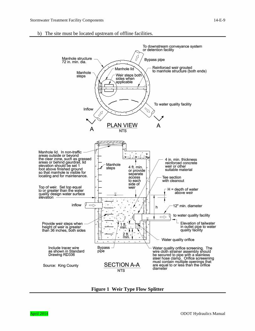
3.1.1 Flow Splitter – Weir Type A typical weir type flow splitter configuration is illustrated in Figure 1. Weir type flow splitters need two compartments to function. The two compartments are created by placing a barrier or also known as a weir across the center of the manhole. The upstream compartment contains the upstream conveyance system inlet pipe and the conveyance pipe that drains into the stormwater treatment facility. All flows up to the water quality peak flow exit the flow splitter manhole by way of the stormwater treatment facility pipe and into the downstream treatment facility. The downstream compartment contains the bypass pipe. Flow depths greater than the height of the weir overtops the weir and is known as bypass flow. These flows are routed into the downstream conveyance system or detention facility. 3.1.1.1 Design Criteria for Weir Type Flow Splitter This section describes the features of a weir type flow splitter and the design criteria that apply specifically to these installations. Site Selection 1. General siting requirements are discussed in Section 14.9. Additional siting criteria that
apply specifically to flow splitters include:
a) The site must be of sufficient size to accommodate the inlet structure and maintenance access
ODOT Hydraulics Manual April 2014
Stormwater Treatment Facility Components 14-E-9
b) The site must be located upstream of offline facilities.
Figure 1 Weir Type Flow Splitter
April 2014 ODOT Hydraulics Manual
14-E-10 Stormwater Treatment Facility Components
Weir Type Flow Splitter manhole Dimensions 1. The minimum manhole diameter is 72 inches. 2. The minimum depth between top of weir and bottom of manhole cover is 4 feet (see figure
1). Avoid Inlet structure depths greater than 20 feet due to the limitations of vactor trucks. Adjacent access to the inlet structure is needed for the vactor to operate to this maximum depth. Therefore, verify access is appropriate by coordinating the design with the Maintenance District.
Weir Type Flow Splitter Features 1. The flow splitting weir should be centered within the manhole. The top of weir is set equal
to or greater than the stormwater treatment facility design water surface elevation. Verify the weir can bypass the design high flow without adversely impacting the upstream conveyance system. The design high flow is calculated using the same design storm as the upstream conveyance system. Modify design as needed. Note: The goal is to establish a splitter configuration that achieves the largest outlet pipe and minimizes the weir height.
2. Provide water quality orifice screening to protect orifice from plugging for all orifices 6
inches or less. Orifice screen must contain multiple openings that are equal to or less than the orifice diameter.
3. Bypass piping shall be designed using the same design criteria as the upstream conveyance
system. The minimum pipe size is 12 inches. 4. Water quality piping shall be designed using the water quality peak discharge. The
minimum pipe size is 12 inches. Sediment Control 1. Provide a sump with a minimum depth of 2 feet. Maintenance and Inspection Access 1. Provide access to each side of weir if the height between the top of the weir and the bottom
of the manhole cover is less than 4 feet. 2. Provide a ladder on each side of weir if height of weir is greater than 3 feet. 3. Provide two manhole lids. Locate one on each side of the weir. 4. Implement with Maintenance District concurrence: Manhole lids located in non-traffic areas
ODOT Hydraulics Manual April 2014
Stormwater Treatment Facility Components 14-E-11
( ) 5.15.0d LHg2C
32
2/3
0.5d
W
L(2g)2C3Q
outside or beyond the clear zone such as grassed areas or behind guardrail must be set 1 foot above finish ground so that manhole location is visible for locating and for maintenance. This should be coordinated with the maintenance districts, lids may be placed flush with the finished grade at the request of the serving maintenance district. Lid elevations must match proposed finish grade in traffic areas.
5. An access road to this structure is required for inspection and maintenance. See the primary
facility’s design criteria section for access road design guidance. 3.1.1.2 Design Procedure for Weir Type Flow Splitter The procedure for designing a weir type flow splitter is presented below. It assumes the treatment facility’s dimensions such as slopes, grades, depth, width, length, etc. are known. Step 1 – Determine top of weir elevation (ETop of Weir). It should be equal to or greater than the
water quality design water surface elevation projected in the facility. Step 2 – Determine the hydraulic head over the bypass weir using the rectangular sharp-
crested weir equation. QW = Where: QW = conveyance peak flow in cubic feet per second
Cd = sharp crested weir coefficient of discharge = 0.60 L = length of weir in feet H = depth of water above weir in feet Rearrange to solve for H: H = Step 3 – Determine water elevation (EWeir) at weir using calculated depth of water above the
weir in Step 2.
EWeir = ETop of Weir + H
Where: ETopf of Weir = top of weir elevation as determined in Step 1 H = depth of water above weir in feet as determined in Step 2
Step 4 – Determine invert elevation for pipe draining into treatment facility.
April 2014 ODOT Hydraulics Manual
14-E-12 Stormwater Treatment Facility Components
( ) 5.0gh2CA
( )
5.0
0.5WQ
2ghCπ4Q
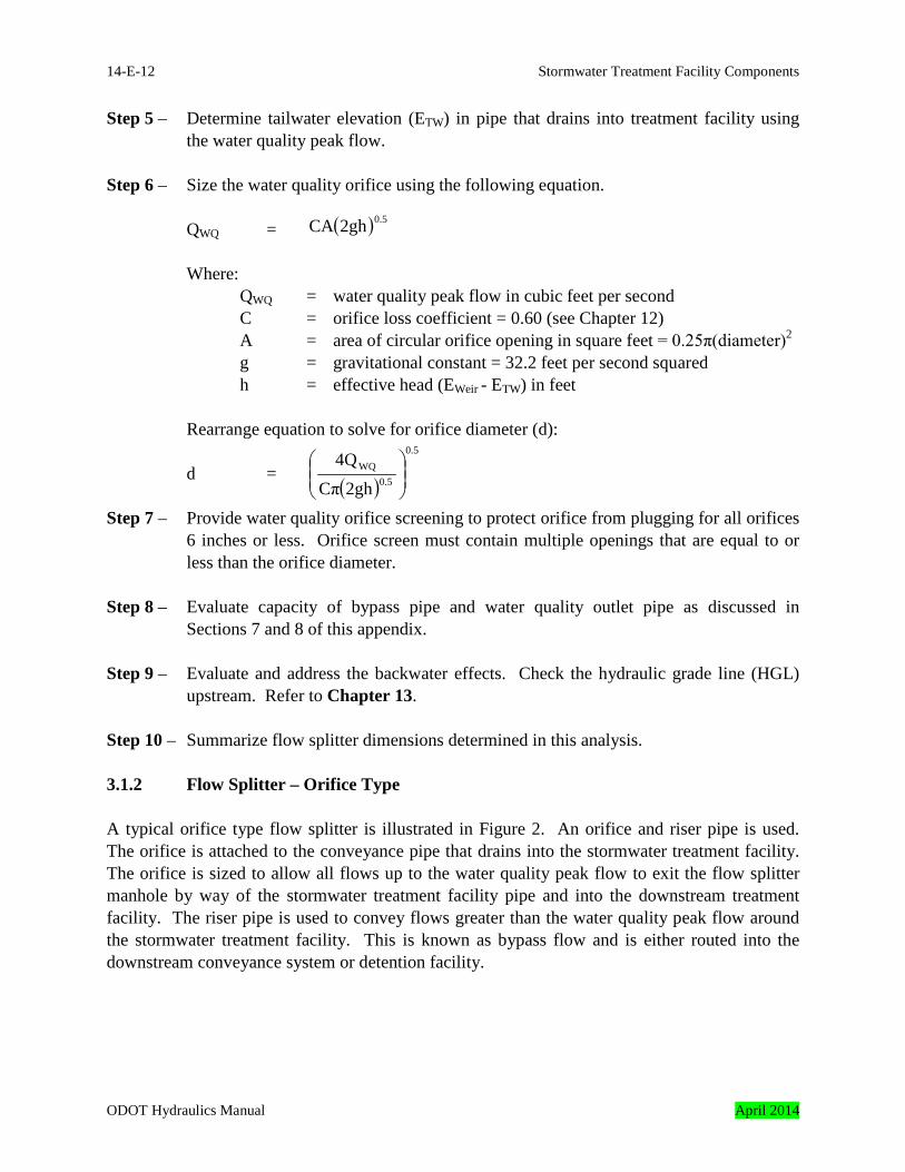
Step 5 – Determine tailwater elevation (ETW) in pipe that drains into treatment facility using the water quality peak flow.
Step 6 – Size the water quality orifice using the following equation.
QWQ = Where:
QWQ = water quality peak flow in cubic feet per second C = orifice loss coefficient = 0.60 (see Chapter 12)
A = area of circular orifice opening in square feet = 0.25π(diameter)2 g = gravitational constant = 32.2 feet per second squared h = effective head (EWeir - ETW) in feet
Rearrange equation to solve for orifice diameter (d): d = Step 7 – Provide water quality orifice screening to protect orifice from plugging for all orifices
6 inches or less. Orifice screen must contain multiple openings that are equal to or less than the orifice diameter.
Step 8 – Evaluate capacity of bypass pipe and water quality outlet pipe as discussed in
Sections 7 and 8 of this appendix. Step 9 – Evaluate and address the backwater effects. Check the hydraulic grade line (HGL)
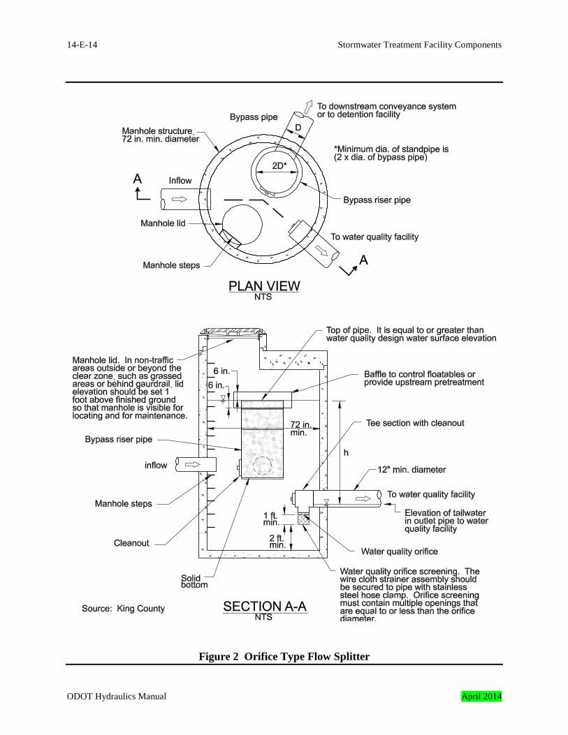
upstream. Refer to Chapter 13. Step 10 – Summarize flow splitter dimensions determined in this analysis. 3.1.2 Flow Splitter – Orifice Type A typical orifice type flow splitter is illustrated in Figure 2. An orifice and riser pipe is used. The orifice is attached to the conveyance pipe that drains into the stormwater treatment facility. The orifice is sized to allow all flows up to the water quality peak flow to exit the flow splitter manhole by way of the stormwater treatment facility pipe and into the downstream treatment facility. The riser pipe is used to convey flows greater than the water quality peak flow around the stormwater treatment facility. This is known as bypass flow and is either routed into the downstream conveyance system or detention facility.
ODOT Hydraulics Manual April 2014

Stormwater Treatment Facility Components 14-E-13
3.1.2.1 Design Criteria for Orifice Type Flow Splitter This section describes the features of an orifice type flow splitter and the design criteria that apply specifically to these installations.
April 2014 ODOT Hydraulics Manual
14-E-14 Stormwater Treatment Facility Components
Figure 2 Orifice Type Flow Splitter
ODOT Hydraulics Manual April 2014
Stormwater Treatment Facility Components 14-E-15
Site Selection 1. General siting requirements are discussed in Section 14.9. Additional siting criteria that
apply specifically to flow splitters include:
a) The site must be of sufficient size to accommodate the inlet structure and maintenance access
b) The site must be located upstream of the BMP
Orifice Type Flow Splitter Manhole Dimensions 1. The minimum manhole diameter is 72 inches. 2. Avoid Inlet structure depths greater than 20 feet due to the limitations of vactor trucks.
Adjacent access to the inlet structure is needed for the vactor to operate to this maximum depth. Therefore, verify access is appropriate by coordinating the design with the Maintenance District.
Orifice Type Flow Splitter Features 1. Provide water quality orifice screening to protect orifice from plugging for all orifices 6
inches or less. Orifice screen must contain multiple openings that are equal to or less than the orifice diameter.
2. Bypass riser pipe shall be designed using the same design criteria as the upstream
conveyance system. The riser pipe must be designed so it operates as a weir rather than an orifice (See Section 12.9.4.2). The minimum riser pipe size is two times the diameter of the bypass outlet pipe.
3. Bypass piping is connected to the bypass riser pipe that drains high flows into the
downstream conveyance system or detention facility. Design using the same design criteria as the upstream conveyance system. The minimum pipe size is 12 inches.
4. Water quality piping shall be designed using the water quality peak discharge. The
minimum pipe size is 12 inches. Sediment Control 1. Provide a sump with a minimum depth of 2 feet. Maintenance and Inspection Access 1. Provide a ladder for inspection access and maintenance.
April 2014 ODOT Hydraulics Manual
14-E-16 Stormwater Treatment Facility Components
( )
5.0
0.5WQ
2ghCπ4Q
2. Provide two manhole lids. 3. Manhole lids located in non-traffic areas outside or beyond the clear zone such as grassed
areas or behind guardrail must be set 1 foot above finish ground so that manhole location is visible for locating and for maintenance. This should be coordinated with the maintenance districts, lids may be placed flush with the finished grade at the request of the serving maintenance district. Lid elevations must match proposed finish grade in traffic areas.
4. An access road to this structure is required for inspection and maintenance. See the primary
facility’s design criteria section for access road design guidance. 3.1.2.2 Design Procedure - Orifice Type Flow Splitter The procedure for designing a orifice type flow splitter is presented below. It assumes the treatment facility’s dimensions such as slopes, grades, depth, width, length, etc. are known. Step 1 – Determine top of riser pipe elevation (ETop). It should be equal to or greater than the
water quality design water surface elevation projected in the facility. Step 2 – Determine invert elevation for pipe draining into treatment facility. Step 3 – Determine tailwater elevation (ETW) in pipe that drains into treatment facility using
the water quality peak flow. Step 4 – Size the water quality orifice using the following equation.
d = Where:
QWQ = water quality flow rate in cubic feet per second C = orifice loss coefficient = 0.60 d = diameter of circular orifice opening, in feet g = gravitational constant = 32.2 feet per second squared h = effective head (ETop - ETW) in feet Step 5 – Provide water quality orifice screening to protect orifice from plugging for all orifices
6 inches or less. Orifice screen must contain multiple openings that are equal to or less than the orifice diameter.
ODOT Hydraulics Manual April 2014
Stormwater Treatment Facility Components 14-E-17
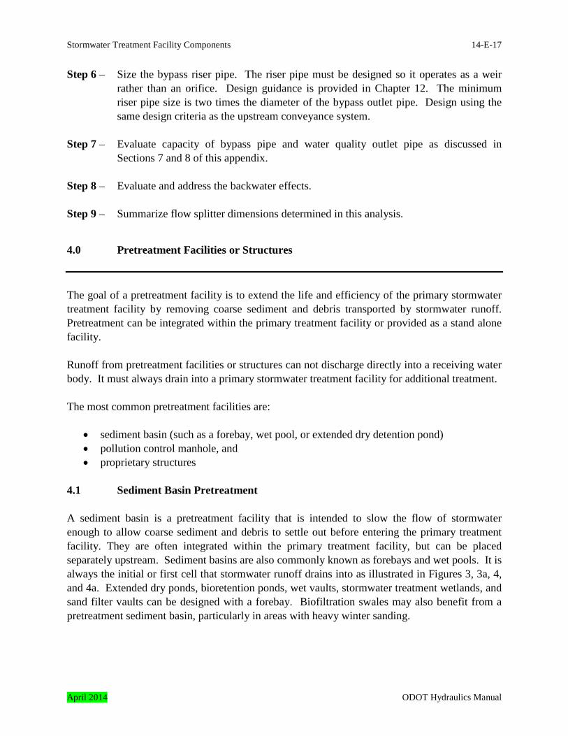
Step 6 – Size the bypass riser pipe. The riser pipe must be designed so it operates as a weir rather than an orifice. Design guidance is provided in Chapter 12. The minimum riser pipe size is two times the diameter of the bypass outlet pipe. Design using the same design criteria as the upstream conveyance system.
Step 7 – Evaluate capacity of bypass pipe and water quality outlet pipe as discussed in
Sections 7 and 8 of this appendix. Step 8 – Evaluate and address the backwater effects. Step 9 – Summarize flow splitter dimensions determined in this analysis. 4.0 Pretreatment Facilities or Structures
The goal of a pretreatment facility is to extend the life and efficiency of the primary stormwater treatment facility by removing coarse sediment and debris transported by stormwater runoff. Pretreatment can be integrated within the primary treatment facility or provided as a stand alone facility. Runoff from pretreatment facilities or structures can not discharge directly into a receiving water body. It must always drain into a primary stormwater treatment facility for additional treatment. The most common pretreatment facilities are:
• sediment basin (such as a forebay, wet pool, or extended dry detention pond) • pollution control manhole, and • proprietary structures
4.1 Sediment Basin Pretreatment A sediment basin is a pretreatment facility that is intended to slow the flow of stormwater enough to allow coarse sediment and debris to settle out before entering the primary treatment facility. They are often integrated within the primary treatment facility, but can be placed separately upstream. Sediment basins are also commonly known as forebays and wet pools. It is always the initial or first cell that stormwater runoff drains into as illustrated in Figures 3, 3a, 4, and 4a. Extended dry ponds, bioretention ponds, wet vaults, stormwater treatment wetlands, and sand filter vaults can be designed with a forebay. Biofiltration swales may also benefit from a pretreatment sediment basin, particularly in areas with heavy winter sanding.
April 2014 ODOT Hydraulics Manual

14-E-18 Stormwater Treatment Facility Components
4.1.1 Design Criteria for a Sediment Basin This section describes the features of a sediment basin and the design criteria that apply specifically to these installations. Site Selection 1. General siting requirements are discussed in Section 14.9. Additional siting criteria that
apply specifically to sediment basins include:
a) The site must be of sufficient size to accommodate the inlet facility and maintenance vehicle access.
b) The site must be located upstream of the BMP. Sediment Basin Geometry 1. The sediment basin bottom area must be flat. 2. Interior side slopes should not be steeper than 1V:4H 3. The sediment basin must have adequate depth to provide the needed storage noted below for
pretreatment and sediment storage (sediment storage is also known as dead storage). 4. The minimum bottom width is 4 feet to provide the needed storage and allow for
maintenance. 5. The sediment basin storage volume is designed to temporarily store 5 to 10 percent of the
primary treatment facility volume. This is in addition to the sediment or dead storage volume. Use 5 percent for limited space applications.
6. Pond walls may be retaining walls designed in accordance with the ODOT Geotechnical
Design Manual. A fence is typically provided along the top of the wall. 7. The basin must be designed to provide a minimum depth of storage of 6 inches for sediment
accumulation. Maintenance Access 1. An access road to the sediment basin is required for inspection and maintenance. See the
primary facility’s design criteria section for access road design guidance.
ODOT Hydraulics Manual April 2014
Stormwater Treatment Facility Components 14-E-19
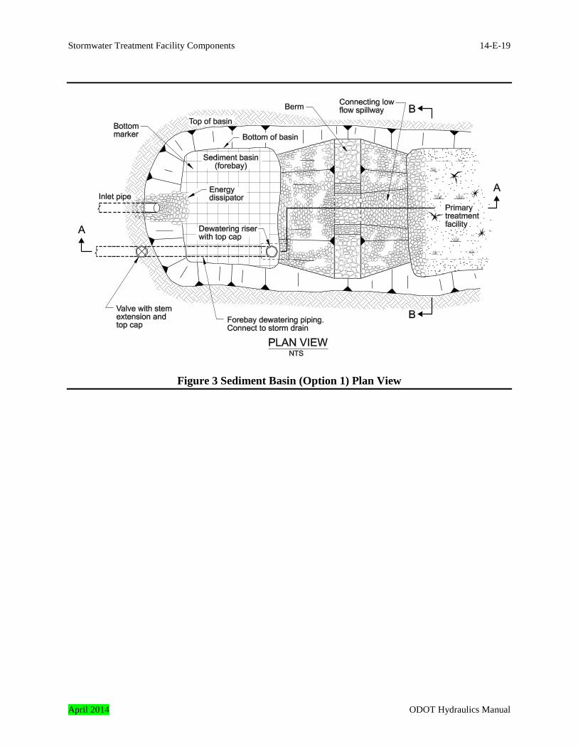
Figure 3 Sediment Basin (Option 1) Plan View
April 2014 ODOT Hydraulics Manual
14-E-20 Stormwater Treatment Facility Components
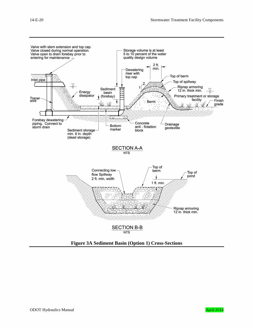
Figure 3A Sediment Basin (Option 1) Cross-Sections
ODOT Hydraulics Manual April 2014
Stormwater Treatment Facility Components 14-E-21
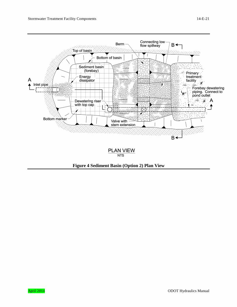
Figure 4 Sediment Basin (Option 2) Plan View
April 2014 ODOT Hydraulics Manual
14-E-22 Stormwater Treatment Facility Components
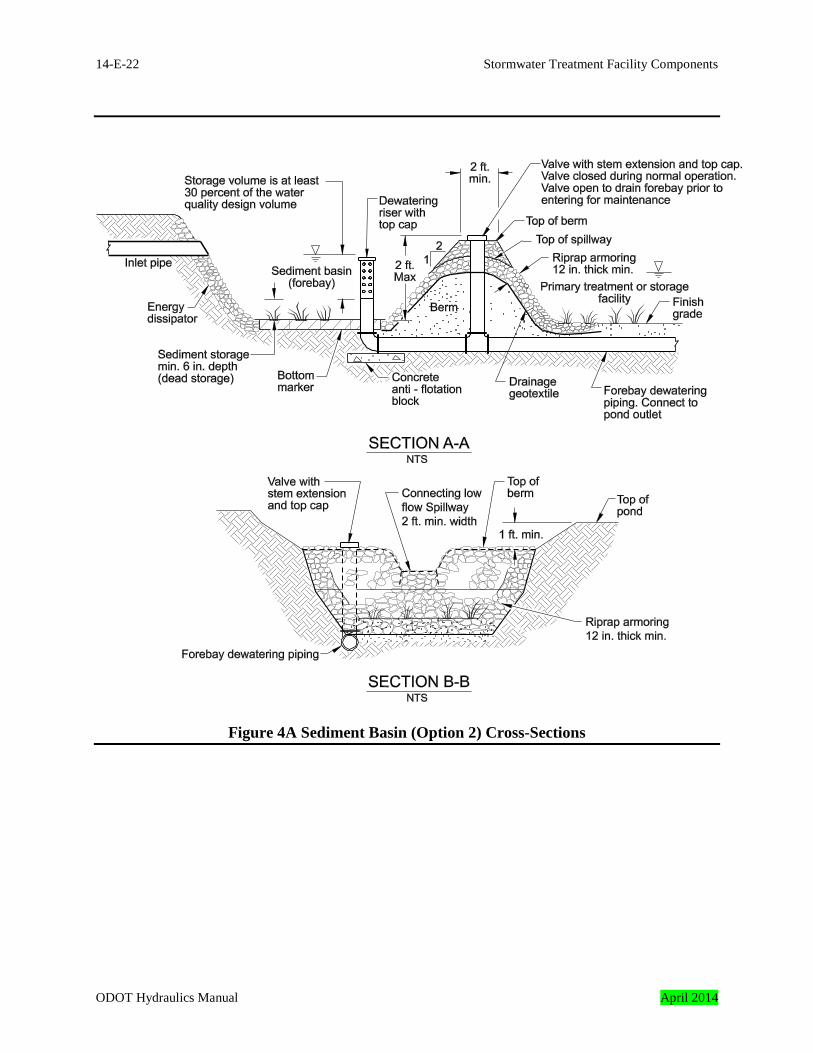
Figure 4A Sediment Basin (Option 2) Cross-Sections
ODOT Hydraulics Manual April 2014
Stormwater Treatment Facility Components 14-E-23
Bottom Marker 1. A bottom marker made of porous pavers must be installed along the basin bottom for
maintenance vehicle and mowing equipment access. Select a porous paver from the Qualified Products List. The porous paver must provide a minimum 80 percent bottom area opening for grass growth. Spaced solid paver blocks are not allowed.
Energy Dissipator 1. The side slope around the inlet pipe shall be armored with riprap. Armor using riprap
designed to the same design storm as the upstream conveyance system. The minimum depth of riprap is 12-inches.
Dewatering Riser 1. A dewatering riser is optional, and is only opened to remove water from the sediment basin
to allow for maintenance. The riser assembly has three components: 1. Riser pipe with top cap. The pipe is perforated from the top down to just above
the dead (sediment) storage elevation. 2. Forebay dewatering pipe, which connects the riser pipe to the primary BMP
outfall or other downstream conveyance system. 3. Valve with stem extension and top cap. The valve is located downstream of the
riser pipe, and should be placed for easy access. Spillway Berm 1. The top, downstream side slope, and toe of the spillway berm shall be armored with
riprap. Armor using riprap designed to the same design criteria as the upstream conveyance system. The minimum depth of riprap is 12-inches.
2. The side slopes should not be steeper that 1V:4H 3. The low flow spillway minimum width is 2 feet. 4. The low flow spillway elevation should not be greater than the water quality design
elevation. Safety Features Exclusionary measures may be required to prevent entry into facilities that present a hazard to children and, to a lesser extent, all persons. Fences are recommended around these facilities where one or more of the following conditions exist:
April 2014 ODOT Hydraulics Manual
14-E-24 Stormwater Treatment Facility Components
• areas where small children are present, particularly in residential areas and close to schools
and playgrounds • areas where rapid water level increases would make escape practically impossible, • water depths exceed 3 feet for more than 24 hours, • basin bottom is permanently wet and has side slopes steeper than 1V:3H, or 4.2 Pollution Control Manhole A pollution control manhole is used to capture sediment and trap floatable debris/oils. They consist of a large diameter manhole and an outlet cross tee. Details of this pretreatment structure are shown on Standard Drawing RD340. They are suitable for built-up areas where space is at a premium. Extended dry ponds, bioretention facilities, media filter BMPs, wet vaults, stormwater treatment wetlands, sand filter vaults and sand filters can use pollution control manholes for pretreatment. 4.2.1 Design Criteria for a Pollution Control Manhole Site Selection 1. General siting requirements are discussed in Section 14.9. Additional siting criteria that
apply specifically to pollution control manholes include:
a) The site must be of sufficient size to accommodate the structure and maintenance vehicle access
b) The site must be located upstream of a BMP. Pollution Control Manhole Geometry 1. The minimum manhole diameter is 72 inches. 2. Avoid structure depths greater than 20 feet due to the limitations of ODOT vactor trucks. Maintenance and Inspection Access 1. Provide a ladder for inspection access and maintenance. 2. Manhole lids located in non-traffic areas such as grassed areas or behind guardrail must be
set 1 foot above finish ground so that manhole location is visible for locating and for maintenance. This should be coordinated with the maintenance districts, lids may be placed flush with the finished grade at the request of the serving maintenance district Lid elevations must match proposed finish grade in traffic areas.
ODOT Hydraulics Manual April 2014
Stormwater Treatment Facility Components 14-E-25
3. An access road to this structure is required for inspection and maintenance. See the primary facility’s design criteria section for access road design guidance.
4.3 Proprietary Structures Several proprietary structures are available for stormwater pretreatment. These structures are briefly discussed in Sections 14.8.5 and 14.8.6. The reader is referred to the various manufacturers for more detailed information on the products discussed. 5.0 Flow Spreading Options
Several stormwater treatment facilities require uniform sheet flow as runoff enters and flows along the intended treatment path. Swales, dispersion areas and sand filters are treatment facilities that require flow spreaders to maintain uniform sheet flow during the treatment process. The most common flow spreaders are the:
• Concrete basin • Rock basin • Anchored board
5.1 Concrete Basin Flow Spreader
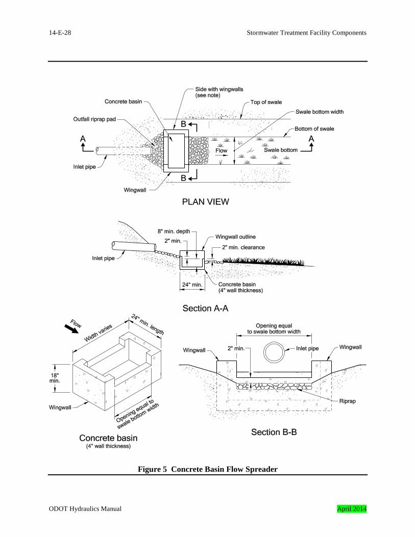
This flow spreader technique utilizes a box with sump to assist with maintaining sheet flow. It is typically installed downstream of the stormwater treatment facility inlet pipe. The goal is to allow the concentrated runoff from the inlet pipe to outfall into the box spreader. Runoff leaves the box spreader by spilling over the level downstream wall of the box spreader as sheet flow. A concrete basin flow spreader should be used with swales and sand filters. See Figure 5. 5.1.1 Design Criteria for Concrete Basin Flow Spreader This section describes the features of a concrete basin flow spreader and the design criteria that apply specifically to these installations.
Concrete Basin Flow Spreader Geometry 1. Provide a minimum sump depth of 8-inches. The sump depth is the distance between the
top of the downstream basin wall and the bottom of the concrete basin.
April 2014 ODOT Hydraulics Manual

14-E-26 Stormwater Treatment Facility Components
2. Provide a width that extends 6 inches (both ends) beyond the width of the treatment path or
swale bottom width. The width is shown and noted in Figure 5. 3. Provide a minimum length of 24-inches. The length is shown and noted in Figure 5. 4. Wingwalls must be 4 inches higher than the bottom of the facility. 5. The portion of the downstream wall that will serve as the weir to spread flows must be two
inches higher than the bottom of the facility. 6. The Upstream wall must be 2 inches higher than the downstream wall. 5.2 Rock Basin Flow Spreader
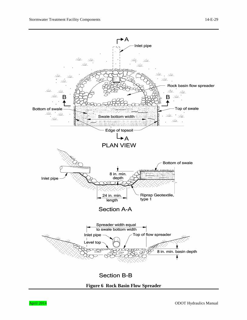
This flow spreader technique utilizes a basin lined with rock to assist with maintaining sheet flow. It is typically installed downstream of the stormwater treatment facility inlet pipe. The concentrated runoff from the inlet pipe outfalls into the rock spreader. Runoff leaves the basin by spilling over the level downstream portion of the basin spreader as sheet flow. 5.2.1 Design Criteria for Rock basin Flow Spreader This section describes the features of a rock basin flow spreader and the design criteria that apply specifically to these installations. See Figure 6.
Rock basin Flow Spreader Geometry 1. Provide a minimum sump depth of 8-inches. The sump depth is the distance between the top
of the downstream rock and the bottom of the rock basin. 2. Provide a width that equals the width of the treatment path or swale bottom width. The
width is shown and noted in Figure 6. 3. Provide a minimum length of 24-inches. The length is shown and noted in Figure 8.
ODOT Hydraulics Manual April 2014
Stormwater Treatment Facility Components 14-E-27
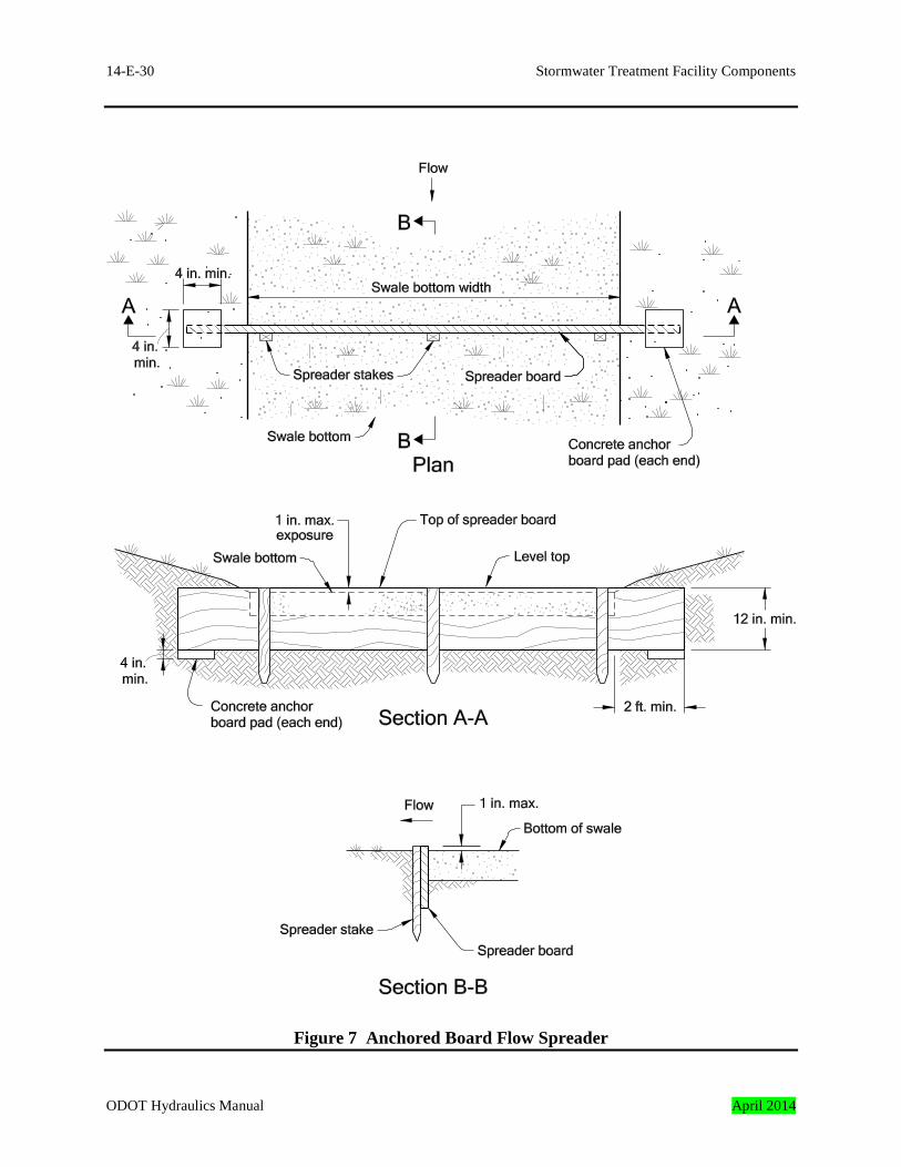
5.3 Anchored Board Flow Spreader This flow spreader technique utilizes a plate or board to assist with maintaining sheet flow. See Figure 7. Anchored board flow spreaders are typically installed every 50 feet along swales to maintain sheet flow. The goal is to allow the concentrated runoff from the inlet pipe to drain up to the plate and forcing the flowing water to spread along the upstream face of the board. Runoff spills over the board as sheet flow when flow depths exceed the board height. An anchored board flow spreader should be used with swales and sand filters. 5.3.1 Design Criteria for Anchored Board Flow Spreader This section describes the features of an anchored board flow spreader and the design criteria that apply specifically to these installations. Anchored Board Flow Spreader Geometry 1. Provide a width that extends 2 feet (both ends) beyond the width of the treatment path or
swale bottom width. The width is shown and noted in Figure 7. 2. Provide a maximum exposure height of 1 inch measured at the upstream face of the
anchored board. This is the height between the top of anchored board and the bottom of the facility.
Anchor Board Pad 1. Provide a 4-inch wide by 4-inch long anchor board pad along each end of board as shown in
figure 7.
April 2014 ODOT Hydraulics Manual
14-E-28 Stormwater Treatment Facility Components
Figure 5 Concrete Basin Flow Spreader
ODOT Hydraulics Manual April 2014
Stormwater Treatment Facility Components 14-E-29
Figure 6 Rock Basin Flow Spreader
April 2014 ODOT Hydraulics Manual
14-E-30 Stormwater Treatment Facility Components
Figure 7 Anchored Board Flow Spreader
ODOT Hydraulics Manual April 2014
Stormwater Treatment Facility Components 14-E-31
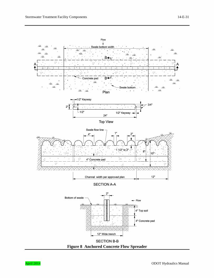
Figure 8 Anchored Concrete Flow Spreader
April 2014 ODOT Hydraulics Manual
14-E-32 Stormwater Treatment Facility Components
5.4 Anchored Concrete Flow Spreader This flow spreader technique utilizes a formed concrete strip to assist with maintaining sheet flow. See Figure 8. Anchored concrete flow spreaders are typically installed every 50 feet along swales to maintain sheet flow. The goal is to force flowing water in the swale to spread along the upstream face of the flow spreader and drain through the spaced gaps. An anchored concrete flow spreader is used in swales. 5.4.1 Design Criteria for Anchored Concrete Flow Spreader This section describes the features of an anchored concrete flow spreader and the design criteria that apply specifically to these installations. Anchored Concrete Flow Spreader Geometry 1. Provide a width that extends 12 inches (both ends) beyond the width of the treatment path or
swale bottom width. The width is shown and noted in Figure 8. 2. Provide an exposure height of 1-1/2 to 2 inches measured at the upstream face of the
anchored spreader. This is the height between the top of anchored spreader and the bottom of the facility.
Anchor Pad 1. Provide a 4-inch high by 12-inch wide anchor pad along the entire length as shown in figure
8.
ODOT Hydraulics Manual April 2014
Stormwater Treatment Facility Components 14-E-33
6.0 Outlet Control Structures
An outlet control structure is needed to control flow leaving the stormwater treatment facility. In most cases the outlet structure consists of a catch basin or manhole, water quality flow control feature and a high flow bypass feature. Its primary functions are:
• To only allow runoff flows up to the water quality design flow to exit the water quality facility.
• To bypass high flows through the stormwater treatment facility. This is common when combined facilities are proposed for a project.
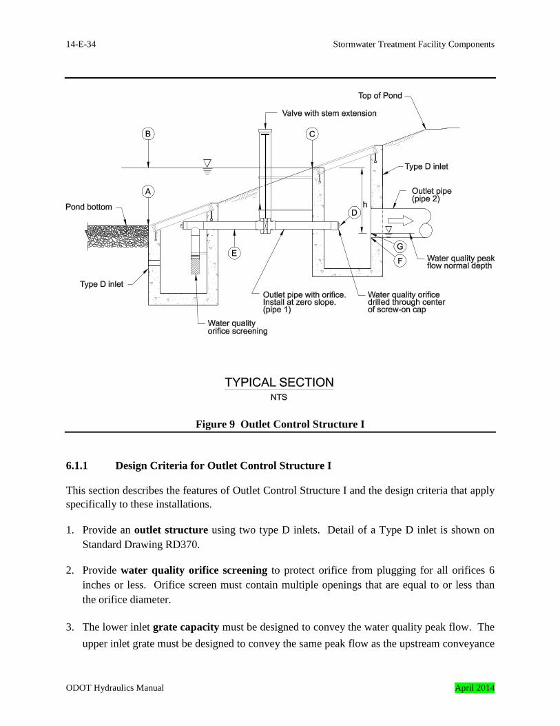
The following design guidance and criteria is for the most common types of outlet control structures used in stormwater treatment facility design. Other outlet control methods may be proposed but must perform the primary functions of a stormwater treatment facility outlet structure (see above). 6.1 Outlet Control Structure I Outlet Control Structure I is most commonly used with extended detention dry ponds. It is illustrated in Figure 9. It is designed to release the water quality event over a 48 hour period and to pass high flows. Outlet Control Structure I uses two type D inlets and an orifice to function. The lower inlet controls the flow by using an attached orifice that drains the water quality volume over a period of 48 hours and the high flows drain into the upper inlet that routes these flows into the downstream conveyance system or detention facility.
April 2014 ODOT Hydraulics Manual
14-E-34 Stormwater Treatment Facility Components
Figure 9 Outlet Control Structure I 6.1.1 Design Criteria for Outlet Control Structure I This section describes the features of Outlet Control Structure I and the design criteria that apply specifically to these installations.
1. Provide an outlet structure using two type D inlets. Detail of a Type D inlet is shown on Standard Drawing RD370.
2. Provide water quality orifice screening to protect orifice from plugging for all orifices 6 inches or less. Orifice screen must contain multiple openings that are equal to or less than the orifice diameter.
3. The lower inlet grate capacity must be designed to convey the water quality peak flow. The upper inlet grate must be designed to convey the same peak flow as the upstream conveyance
ODOT Hydraulics Manual April 2014
Stormwater Treatment Facility Components 14-E-35
system. An emergency spillway or auxiliary outlet is needed if the upper inlet grate could not convey the appropriate peak flow. Auxiliary outlet design guidance is provided in Section 7 of this appendix.
4. Provide valve with stem extension that is connected to the outlet pipe with orifice to provide an emergency shut-off mechanism in-case of a hazmat spill. Stem extension should extend above the water quality design surface elevation.
6.1.2 Design Procedure for Outlet Control Structure I The procedure for designing Outlet Control Structure I is presented below. It assumes the treatment facility’s dimensions such as slopes, grades, depth, width, length, etc. are known. Step 1 – Determine the lip elevation (ELower, point A, Figure 9) of the lower inlet grate. It
should be equal to the pond bottom elevation. Step 2 – Determine the water quality design water surface elevation (EWS, Point B, Figure 9).
The depth (D) of the water quality volume is determined in design procedure step 3 in Appendix D. Therefore,
EWS = ELower + D Step 3 – Determine the lip elevation (EUpper, point C, Figure 9) of the upper inlet grate. It
should be equal to the water quality design water surface elevation (EWS). Step 4 – Determine the orifice centroid elevation (EOrifice, point D, Figure 9). It should be
equal to the pond bottom elevation. Step 5 – Determine the outlet pipe with orifice (Pipe1) flow line elevation (EPipe1, point E,
Figure 9). It should be equal to the pond bottom elevation minus one-half the diameter of Pipe1.
Step 6 – Determine the outlet pipe (Pipe2) invert elevation (EPipe2, point F, Figure 9). It should
always be lower than the orifice centroid elevation to allow for positive drainage. Step 7 – Size Pipe2 for high flow. See design guidance in Section 8 of this appendix. Step 8 – Determine the water quality peak flow using the water quality design storm
determined in Step 1 in Appendix D. Step 9 – Determine the normal depth (yn) of flow in Pipe2 using the water quality peak flow
from step 8. The normal depth can be calculated using the Manning Equation. See
April 2014 ODOT Hydraulics Manual
14-E-36 Stormwater Treatment Facility Components
Chapter 8 for design guidance.
Step 10 – Determine the water quality flow elevation in Pipe2 (EWQ, point G, Figure 9).
Therefore,
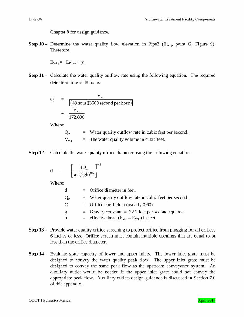
EWQ = EPipe2 + yn Step 11 – Calculate the water quality outflow rate using the following equation. The required
detention time is 48 hours.
Qo = ( )( )[ ]hourper second 3600hour 48Vwq
= 172,800
Vwq
Where: Qo = Water quality outflow rate in cubic feet per second. Vwq = The water quality volume in cubic feet. Step 12 – Calculate the water quality orifice diameter using the following equation.
d = 0.5
0.5o
πC(2gh)4Q
Where: d = Orifice diameter in feet.
Qo = Water quality outflow rate in cubic feet per second. C = Orifice coefficient (usually 0.60). g = Gravity constant = 32.2 feet per second squared.
h = effective head (EWS – EWQ) in feet Step 13 – Provide water quality orifice screening to protect orifice from plugging for all orifices
6 inches or less. Orifice screen must contain multiple openings that are equal to or less than the orifice diameter.
Step 14 – Evaluate grate capacity of lower and upper inlets. The lower inlet grate must be
designed to convey the water quality peak flow. The upper inlet grate must be designed to convey the same peak flow as the upstream conveyance system. An auxiliary outlet would be needed if the upper inlet grate could not convey the appropriate peak flow. Auxiliary outlets design guidance is discussed in Section 7.0 of this appendix.
ODOT Hydraulics Manual April 2014
Stormwater Treatment Facility Components 14-E-37
Step 15 – Evaluate and address hydraulic grade line effects to assure proper operation under
design conditions. 7.0 Auxiliary Outlets
Auxiliary Outlets are provided if the primary outlet control structure can not safely pass the projected high flows. Broad-crested spillway weirs and overflow risers are the two most common auxiliary outlets used in stormwater treatment facility design. Additional discussion on auxiliary outlets is presented in Chapter 12. 7.1 Design Criteria for Auxiliary Outlets The design criteria discussed in Chapter 12 are recommended for designing stormwater treatment facility auxiliary outlets. 7.1.1 Design Procedure for Auxiliary Outlets The following steps outline how to size auxiliary outlets for stormwater treatment facilities: Step 1 – Determine the design storm used to analyze the upstream conveyance system. The
auxiliary outlet would be sized using the same storm. For example, the design recurrence interval for the conveyance system upstream of a proposed extended dry pond is the 10-year, 24 hour storm then the treatment facility piping would be designed using the same storm event.
Step 2 – The design discharge is calculated using hydrology guidance in Chapter 7. Use the
storm drainage design recurrence interval obtained from step 1. Step 3 – Size the auxiliary outlet using the design discharge calculated in step 2. Designing
auxiliary outlets is discussed in Chapter 12. Note: Evaluate grate capacity when a catch basin is used as the auxiliary outlet. The inlet grate must be designed to convey the same peak flow as the upstream conveyance system.
April 2014 ODOT Hydraulics Manual
14-E-38 Stormwater Treatment Facility Components
8.0 Storm Drain Piping
Storm drain piping is required to drain runoff into and out of the stormwater treatment facility. 8.1 Design Criteria for Storm Drain Piping The design criteria discussed in Chapter 13 are recommended for sizing stormwater treatment facility storm drain piping. 8.1.1 Design Procedure for Storm Drain Piping The following steps outline how to size storm drain piping for stormwater treatment facilities: Step 1 – Determine the design storm used to analyze the upstream storm drain system. All
stormwater treatment facility piping would be sized using the same storm. For example, the design recurrence interval for the conveyance system upstream of a proposed extended dry pond is the 10-year, 24 hour storm then the treatment facility piping would be designed using the same storm event.
Step 2 – The design discharge is calculated using hydrology guidance in Chapter 7. The
rational method should be used to determine the design discharge using the storm drainage design recurrence interval obtained from step 1.
Step 3 – Determine the appropriate pipe size using the design discharge calculated in step 2.
The minimum pipe size is 12-inches in diameter. The methods discussed in Chapter 13 are recommended for sizing storm drain piping.
Step 4 – Evaluate and address hydraulic grade line effects to assure proper operation under
design conditions.
ODOT Hydraulics Manual April 2014
Stormwater Treatment Facility Components 14-E-39
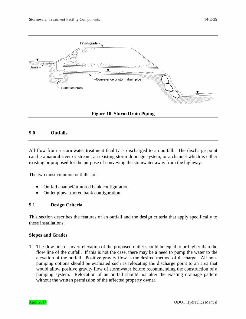
Figure 10 Storm Drain Piping 9.0 Outfalls
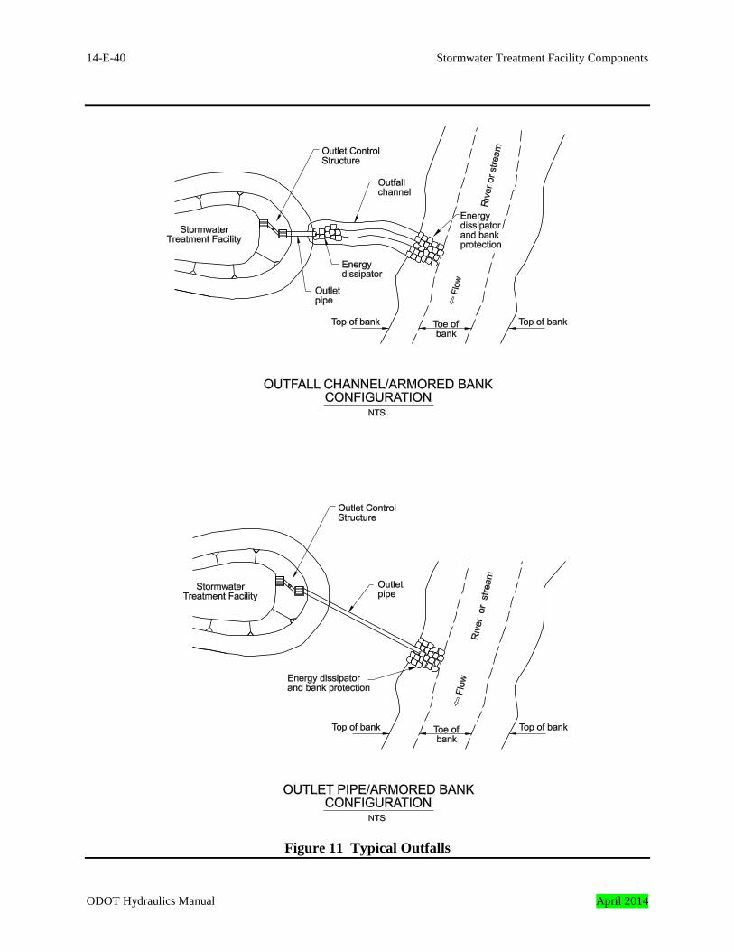
All flow from a stormwater treatment facility is discharged to an outfall. The discharge point can be a natural river or stream, an existing storm drainage system, or a channel which is either existing or proposed for the purpose of conveying the stomwater away from the highway. The two most common outfalls are:
• Outfall channel/armored bank configuration • Outlet pipe/armored bank configuration
9.1 Design Criteria This section describes the features of an outfall and the design criteria that apply specifically to these installations. Slopes and Grades 1. The flow line or invert elevation of the proposed outlet should be equal to or higher than the
flow line of the outfall. If this is not the case, there may be a need to pump the water to the elevation of the outfall. Positive gravity flow is the desired method of discharge. All non-pumping options should be evaluated such as relocating the discharge point to an area that would allow positive gravity flow of stormwater before recommending the construction of a pumping system. Relocation of an outfall should not alter the existing drainage pattern without the written permission of the affected property owner.
April 2014 ODOT Hydraulics Manual
14-E-40 Stormwater Treatment Facility Components
Figure 11 Typical Outfalls
ODOT Hydraulics Manual April 2014
Stormwater Treatment Facility Components 14-E-41
Open Channel Capacity 1. Outfall channels convey flow from a stormwater treatment facility to a natural waterbody.
They are typically composed of prismatic shapes where nearly uniform flow occurs.
A capacity evaluation is required to assure the channel can convey the design discharge. The design criteria discussed in Section 14.10.12 and Chapter 8 are recommended for sizing stormwater treatment facility outfall channels.
Open Channel Stability 1. Outfall channels are typically lined with grass, riprap, or other protective linings. These
linings must be able to withstand the shear stresses from hydrodynamic forces created by the expected peak flows in the channel.
A channel lining stability evaluation is required to assure the channel will be stable. The evaluation consists of verifying the maximum shear stress caused by the design flow must be less than the maximum shear stress the lining can resist without particle movement. The design criteria discussed in Section 14.10.12 and Chapter 8 are recommended for evaluating stormwater treatment facility outfall channels.
Energy Dissipation 1. Energy dissipators are used to reduce the velocity and erosion potential of flowing water.
Protection is usually required at the outlet of stormwater treatment facilities that discharge onto embankments and into natural or unlined channels.
The design criteria discussed in Section 14.10.13 and Chapter 11 are recommended for sizing stormwater treatment facility outfall energy dissipation.
Bank Protection 1. Outfalls located along the banks of rivers and streams need to function as energy dissipators
and bank protection to prevent erosion. If erosion of the embankment is to be prevented, bank protection must be anticipated and the proper type and amount of protection must be provided in the right locations.
The design criteria discussed in Chapter 8 should be used for stream and river discharges less than 50 cubic feet per second. The design criteria discussed in Chapter 15 should be used for channel bank protection and linings on streams and rivers having design discharges greater than 50 cubic feet per second.
April 2014 ODOT Hydraulics Manual
14-E-42 Stormwater Treatment Facility Components
9.1.1 Design Procedure for Stormwater Treatment Facility Outfalls The following are general steps to design the outfalls shown in Figure 11: Step 1 – Determine the design storm used to analyze the upstream conveyance system. All
stormwater treatment facility piping would be sized using the same design storm. For example, the design recurrence interval for the conveyance system upstream of a proposed extended dry pond is the 10-year, 24 hour storm then the treatment facility outfall features would be designed using the same storm event. Outfalls located in a waterway’s floodplain must be designed to conform to the local floodplain regulations.
Step 2 – The design discharge is calculated using hydrology guidance in Chapter 7.
Determine the design discharge using the storm drainage design recurrence interval obtained from step 1.
Outfall channel/armored bank The following steps outline how to design the outfall shown in Figure 11 (outfall channel/ armored bank): Step 1 – Establish typical channel cross-section. Provide adequate drainage depth and side
slopes considering safety, maintenance and access. Step 2 – Determine channel grade(s). Provide a minimum grade of 0.3 percent to minimize
ponding and sediment accumulation. Step 3 – Determine channel liner type and roughness. See Chapter 8. Step 4 – Calculate the flow depth using the design discharge calculated above. The Manning’s
equation or nomograph is recommended to calculate the flow depth. These methods are discussed in Chapter 8.
Step 5 – One or more of these changes may be needed if flow is deeper than maximum
allowable flow depth including freeboard:
• increase bottom width
ODOT Hydraulics Manual April 2014
Stormwater Treatment Facility Components 14-E-43
• make channel side slopes flatter • make channel slope steeper, or • provide smoother channel lining
Step 6 – Calculate the maximum shear stress on lining. See Chapter 8. Compare maximum
to permissible shear stress for all linings except riprap. Go to step 6.2 for riprap lining.
Step 6.1 – Reduce maximum shear stress by one or more of the following if maximum shear
stress is greater than allowable:
• enlarging channel • reducing the channel slope, or • flattening the bank side slopes
or Increase the allowable shear stress by changing the lining material.
Step 6.2 – Calculate D50 needed to resist displacement for riprap lining. Compare D50 needed to D50 provided. Reduce the D50 needed by:
• enlarging channel • changing the channel slope, or • flattening the bank side slopes or Increase the D50 of the liner.
Step 7 – Verify that the depth of flow in the ditch is within allowable limits if liner roughness or channel cross-section is changed.
Step 8 – Design energy dissipation. See Chapter 11. Step 9 – Design bank protection. Use the design criteria discussed in Chapter 8 for stream
and river discharges less than 50 cubic feet per second. Use the design criteria discussed in Chapter 15 for channel bank protection and linings on streams and rivers having design discharges greater than 50 cubic feet per second.
April 2014 ODOT Hydraulics Manual

14-E-44 Stormwater Treatment Facility Components
Outlet pipe/armored bank The following steps outline how to design the outfall shown in Figure 11 (outlet pipe/armored bank): Step 1 – Design energy dissipation. See Chapter 11. Step 2 – Design bank protection. Use the design criteria discussed in Chapter 8 for stream or
river discharges less than 50 cubic feet per second. Use the design criteria discussed in Chapter 15 for channel bank protection and linings on streams and rivers having design discharges greater than 50 cubic feet per second.
ODOT Hydraulics Manual April 2014